EP3020603A1 - Einrichtung zur vermeidung von auffahrunfällen und ihr funktionssystem - Google Patents
Einrichtung zur vermeidung von auffahrunfällen und ihr funktionssystem Download PDFInfo
- Publication number
- EP3020603A1 EP3020603A1 EP14811347.5A EP14811347A EP3020603A1 EP 3020603 A1 EP3020603 A1 EP 3020603A1 EP 14811347 A EP14811347 A EP 14811347A EP 3020603 A1 EP3020603 A1 EP 3020603A1
- Authority
- EP
- European Patent Office
- Prior art keywords
- vehicle
- signal
- brake light
- brake
- control unit
- Prior art date
- Legal status (The legal status is an assumption and is not a legal conclusion. Google has not performed a legal analysis and makes no representation as to the accuracy of the status listed.)
- Granted
Links
Images
Classifications
-
- B—PERFORMING OPERATIONS; TRANSPORTING
- B60—VEHICLES IN GENERAL
- B60Q—ARRANGEMENT OF SIGNALLING OR LIGHTING DEVICES, THE MOUNTING OR SUPPORTING THEREOF OR CIRCUITS THEREFOR, FOR VEHICLES IN GENERAL
- B60Q1/00—Arrangement of optical signalling or lighting devices, the mounting or supporting thereof or circuits therefor
- B60Q1/26—Arrangement of optical signalling or lighting devices, the mounting or supporting thereof or circuits therefor the devices being primarily intended to indicate the vehicle, or parts thereof, or to give signals, to other traffic
- B60Q1/44—Arrangement of optical signalling or lighting devices, the mounting or supporting thereof or circuits therefor the devices being primarily intended to indicate the vehicle, or parts thereof, or to give signals, to other traffic for indicating braking action or preparation for braking, e.g. by detection of the foot approaching the brake pedal
- B60Q1/448—Arrangement of optical signalling or lighting devices, the mounting or supporting thereof or circuits therefor the devices being primarily intended to indicate the vehicle, or parts thereof, or to give signals, to other traffic for indicating braking action or preparation for braking, e.g. by detection of the foot approaching the brake pedal specially adapted for vehicles with ABS
-
- B—PERFORMING OPERATIONS; TRANSPORTING
- B60—VEHICLES IN GENERAL
- B60Q—ARRANGEMENT OF SIGNALLING OR LIGHTING DEVICES, THE MOUNTING OR SUPPORTING THEREOF OR CIRCUITS THEREFOR, FOR VEHICLES IN GENERAL
- B60Q1/00—Arrangement of optical signalling or lighting devices, the mounting or supporting thereof or circuits therefor
- B60Q1/26—Arrangement of optical signalling or lighting devices, the mounting or supporting thereof or circuits therefor the devices being primarily intended to indicate the vehicle, or parts thereof, or to give signals, to other traffic
- B60Q1/44—Arrangement of optical signalling or lighting devices, the mounting or supporting thereof or circuits therefor the devices being primarily intended to indicate the vehicle, or parts thereof, or to give signals, to other traffic for indicating braking action or preparation for braking, e.g. by detection of the foot approaching the brake pedal
-
- B—PERFORMING OPERATIONS; TRANSPORTING
- B60—VEHICLES IN GENERAL
- B60Q—ARRANGEMENT OF SIGNALLING OR LIGHTING DEVICES, THE MOUNTING OR SUPPORTING THEREOF OR CIRCUITS THEREFOR, FOR VEHICLES IN GENERAL
- B60Q1/00—Arrangement of optical signalling or lighting devices, the mounting or supporting thereof or circuits therefor
- B60Q1/26—Arrangement of optical signalling or lighting devices, the mounting or supporting thereof or circuits therefor the devices being primarily intended to indicate the vehicle, or parts thereof, or to give signals, to other traffic
- B60Q1/46—Arrangement of optical signalling or lighting devices, the mounting or supporting thereof or circuits therefor the devices being primarily intended to indicate the vehicle, or parts thereof, or to give signals, to other traffic for giving flashing caution signals during drive, other than signalling change of direction, e.g. flashing the headlights or hazard lights
-
- G—PHYSICS
- G01—MEASURING; TESTING
- G01S—RADIO DIRECTION-FINDING; RADIO NAVIGATION; DETERMINING DISTANCE OR VELOCITY BY USE OF RADIO WAVES; LOCATING OR PRESENCE-DETECTING BY USE OF THE REFLECTION OR RERADIATION OF RADIO WAVES; ANALOGOUS ARRANGEMENTS USING OTHER WAVES
- G01S19/00—Satellite radio beacon positioning systems; Determining position, velocity or attitude using signals transmitted by such systems
- G01S19/01—Satellite radio beacon positioning systems transmitting time-stamped messages, e.g. GPS [Global Positioning System], GLONASS [Global Orbiting Navigation Satellite System] or GALILEO
- G01S19/13—Receivers
Definitions
- the present invention relates to a device which warns subsequent vehicles by a blinking of the third brake light that there is a risk of rear-end collisions by temporarily outputting said signal on the basis of three assumptions: Firstly, when the preceding vehicle is about to brake, secondly, when the preceding vehicle greatly reduces its speed and third, when the traffic flows at unusually slow speed.
- This invention solves the problem of rear-end collisions produced on roads and highways by heavy braking, reduced speed or simply by braking.
- the device according to the invention offers considerable advantages over known brake signal devices, the most important of which are the simplicity of construction and utilization of electrical and electronic vehicle components.
- Another important advantage is the use of the GPS system to detect the type of road on which the vehicle is traveling to activate the third brake light signal in the event of an unusually slow ride on freeways and highways to guide the controller.
- a vehicle deceleration warning device including a piezoelectric sensor device connected to the accelerator pedal or the bottom plate for outputting a first signal when subjected to a corresponding load; Contact means connected to one another or to the accelerator pedal or base plate for contacting the piezoelectric sensor after releasing the accelerator pedal to cause the sensor means to output a first signal in response to the change in the load imposed by the contact means on the piezoelectric sensor piezoelectric sensor device is exercised; and switching means connected to the stop lamps and the piezoelectric sensor means for analyzing the first signal generated by the piezoelectric sensor means and for operating the stop lamps in response to the analysis when the first signal is above a predetermined threshold value.
- document ES 2 138 898 A1 describes an automatic accident avoidance system in each type of vehicle including a circuit system connected to the vehicle's electrical circuit, comprising: at least one integrated circuit having means for detecting the safety margin or distance between one vehicle and another preceding one Vehicle and / or a preceding obstacle, the distance of the distance is in relation to the speed of the vehicle, wherein commands are automatically triggered to slow down and / or stop the vehicle to avoid a collision, as well as means for temporary shutdown drive means.
- ES 1 066 558 U the object is to be solved by means of a recording device that records images from a plurality of in-vehicle cameras, a data microprocessor and a warning signal to the driver of the vehicle by the cameras detect the presence and position of an obstacle in front of or behind the vehicle and the data send the presence and the position of the obstacle to the microprocessor, which calculates the position of the relative speed of the obstacle with respect to the vehicle by means of the data obtained from the camera, and a warning signal to the driver according to predetermined values of the position and the relative approach speed between the obstacle and to the vehicle and further activates protection devices according to other predetermined values of position and relative approach speed between the obstacle and the vehicle.
- the solution is very different to that proposed by the present invention.
Abstract
Description
- Die vorliegende Erfindung betrifft eine Einrichtung, die nachfolgende Fahrzeuge durch ein Blinken des dritten Bremslichts davor warnt, dass eine Gefahr von Auffahrunfällen besteht, indem zeitweise besagtes Signal anhand von drei Annahmen abgegeben wird: Erstens, wenn das vorausfahrende Fahrzeug sich anschickt zu bremsen, zweitens, wenn das vorausfahrende Fahrzeug seine Geschwindigkeit stark vermindert und drittens, wenn der Verkehr mit ungewöhnlich langsamer Geschwindigkeit fließt.
- Diese Erfindung löst das Problem der Auffahrunfälle, die auf Straßen und Autobahnen durch starkes Bremsen, durch verminderte Geschwindigkeit oder einfach durch Bremsen erzeugt werden.
- Die erfindungsgemäße Einrichtung bietet erhebliche Vorteile gegenüber bekannten Bremssignal-Einrichtungen, deren wichtigste die Einfachheit der Konstruktion und Ausnutzung elektrischer und elektronischer Fahrzeugkomponenten sind.
- Ein weiterer wichtiger Vorteil ist die Verwendung des GPS-Systems, um die Art der Straße zu erkennen, auf der das Fahrzeug fährt, um im Falle einer ungewöhnlich langsamen Fahrt auf Autobahnen und Schnellstraßen, das Steuergerät anzuleiten das Lichtsignal der dritten Bremsleuchte zu aktivieren.
- Es ist derzeit ein System bekannt, mit dem einige Fahrzeuge ausgestattet sind, durch das die Notbeleuchtung eingeschaltet wird, wenn bei einem plötzlichem Bremsvorgang das ABS-System in Betrieb tritt. Des Weiteren ist die Installation von High-Brightness-LEDs in den Bremsleuchten bekannt, vor allem in der dritten Bremsleuchte, die sich innerhalb eines Bruchteils einer Sekunde vor einer herkömmlichen Glühbirne einschalten.
- Obwohl keine mit der in dieser Beschreibung der vorliegenden Erfindung identische Erfindung aufgefunden wurde, werden im Folgenden die aufgefundenen Dokumente beschrieben, die den mit der Erfindung zusammenhängenden Stand der Technik darstellen.
- So betrifft Dokument
ES 2 051 336 T3 - Dokument
ES 2 138 898 A1 -
ES 1 066 558 U - Die erfindungsmäße Einrichtung zur Vermeidung von Auffahrunfällen wird aus einer elektronischen Steuereinheit gebildet, die mit dem elektronischen Schaltkreis des Fahrzeugs verbunden ist, mit einem Signalempfänger und einem Signalgeber ausgestattet und so programmiert ist, dass in Verbindung mit einer GPS-Antenne (4), einem Gaspedalencoder (7) und der dritten Bremsleuchte (5) folgende Funktionen ausgeführt werden:
- Wenn das Fahrzeug auf einer Autobahn oder einer Schnellstraße mit einer geringeren Geschwindigkeit als die minimal zulässige Geschwindigkeit fährt, empfängt die Steuereinheit ein Signal vom GPS, das an den Signalgeber weitergeleitet wird und die LEDs der dritten Bremsleuchte aktiviert, so dass diese blinkt.
- 0,5 Sekunden vor dem Treten des Bremspedals erkennt der Gaspedalencoder, dass der Fahrer des Fahrzeugs den Fuß abrupt (x Impulse pro Sekunde) von dem Gaspedal zurückgezogen hat und sendet ein Signal an die Steuereinheit, so dass diese wiederum ein Signal an die dritte Bremsleuchte sendet, so dass diese blinkt.
- Falls eine plötzliche Verringerung der Fahrzeuggeschwindigkeit selbst ohne Berührung bzw. Betätigung der Bremse eintritt, empfängt die Steuereinheit ein Signal vom elektronischen Schaltkreis des Fahrzeugs (Multiplexing Fahrzeug) oder des ABS-Computers (im Falle von nicht vorhandenem Multiplexing) und signalisiert dem Sender ein Signal an die dritte Bremsleuchte (5) zu senden, so dass diese blinkt.
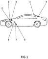
- In Folgenden wird auf eine Figur Bezug genommen, die es ermöglicht, die Beschreibung besser zu verstehen und eine besondere, nicht einschränkende Ausführungsform des Gegenstandes der vorliegenden Erfindung zeigt.
-
Figur 1 : Schematische Darstellung des Fahrzeugs und der Bezugspunkte. In dieser Figur bezeichnen die folgenden Bezugszeichen: - 1.
- Steuereinheit
- 2.
- Signalempfänger
- 3.
- Signalgeber
- 4.
- GPS-Antenne
- 5.
- Dritte Bremsleuchte
- 6.
- Bremspedal
- 7.
- Gaspedalencoder
- 8.
- Gaspedal
- Im Folgenden wird eine bevorzugte Ausführungsform der Erfindung, die nur eine von einer Vielzahl von Bauweisen ist, die sich für die industrielle Verwirklichung eignet, sowie ein oben beschriebener Aufbau beschrieben.
- Eine bevorzugte Ausführungsform der erfindüngsgemäßen Einrichtung zur Vermeidung von Auffahrunfällen kann basierend auf einer elektronischen Steuereinheit (1) verwirklicht werden, die mit dem elektronischen Schaltkreis des Fahrzeugs verbunden ist und mit einem Empfänger (2) und einem Signalgeber (3) ausgestattet ist, und so programmiert ist, dass in Zusammenarbeit mit der GPS-Antenne (4) Antenne, dem Gaspedalencoder (7) und der dritten Bremsleuchte (5) folgende Funktionen ausgeführt werden:
- Wenn das Fahrzeug auf einer Autobahn oder einer Schnellstraße mit einer geringeren Geschwindigkeit als die minimal zulässige Geschwindigkeit fährt, empfängt die Steuereinheit ein Signal von der GPS-Antenne (4), das an den Signalgeber (3) weitergeleitet wird und die LEDs der dritten Bremsleuchte (9) aktiviert, so dass diese blinkt.
- 0,5 Sekunden vor dem Treten des Bremspedals (6) erkennt der Gaspedalencoder (7), dass der Fahrer des Fahrzeugs den Fuß abrupt (x Impulse pro Sekunde) von dem Gaspedal (8) zurückgezogen hat und sendet ein Signal an die Steuereinheit (1), so dass diese wiederum ein Signal an die dritte Bremsleuchte (5) sendet, so dass diese blinkt.
- Falls eine plötzliche Verringerung der Fahrzeuggeschwindigkeit selbst ohne Berührung bzw. Betätigung der Bremse (6) eintritt, empfängt die Steuereinheit (1) ein Signal vom elektronischen Schaltkreis des Fahrzeugs (Multiplexing Fahrzeug) oder des ABS-Computers
- (im Falle von nicht vorhandenem Multiplexing) und signalisiert dem Signalgeber (7) ein Signal an die dritte Bremsleuchte (5) zu senden, so dass diese blinkt.
Claims (1)
- Einrichtung zur Vermeidung von Auffahrunfällen- und entsprechendes Funktionssystem, die/das von einer Steuereinheit (1) gebildet ist, die mit dem elektronischen Schaltkreis des Fahrzeugs verbunden ist und einen Signalempfänger (2) und einen Signalgeber (3) umfasst, dadurch gekennzeichnet, dass in Zusammenarbeit mit einer GPS-Antenne (4), einem Gaspedalencoder (7) und der dritten Bremsleuchte (5) die folgenden Funktionen ausgeführt werden:- Wenn das Fahrzeug auf einer Autobahn oder einer Schnellstraße mit einer geringeren Geschwindigkeit als die minimal zulässige Geschwindigkeit fährt, empfängt die Steuereinheit ein Signal von der GPS-Antenne (4), das an den Signalgeber (3) weitergeleitet wird und die LEDs der dritten Bremsleuchte (9) aktiviert, so dass diese blinkt.- 0,5 Sekunden vor dem Treten des Bremspedals (6) erkennt der Gaspedalencoder (7), dass der Fahrer des Fahrzeugs den Fuß abrupt (x Impulse pro Sekunde) von dem Gaspedal (8) zurückgezogen hat und sendet ein Signal an die Steuereinheit (1), so dass diese wiederum ein Signal an die dritte Bremsleuchte (5) sendet, so dass diese blinkt.- Falls eine plötzliche Verringerung der Fahrzeuggeschwindigkeit selbst ohne Berührung bzw. Betätigung der Bremse (6) eintritt, empfängt die Steuereinheit (1) ein Signal vom elektronischen Schaltkreis des Fahrzeugs (Multiplexing Fahrzeug) oder des ABS-Computers (im Falle von nicht vorhandenem Multiplexing) und signalisiert dem Signalgeber (7) ein Signal an die dritte Bremsleuchte (5) zu senden, so dass diese blinkt.
Priority Applications (2)
| Application Number | Priority Date | Filing Date | Title |
|---|---|---|---|
| EP20164771.6A EP3689682A1 (de) | 2013-06-10 | 2014-06-10 | Einrichtung zur vermeidung von auffahrunfällen und ihr funktionssystem |
| PL14811347T PL3020603T3 (pl) | 2013-06-10 | 2014-06-10 | Układ do unikania wypadków związanych z najechaniem |
Applications Claiming Priority (2)
| Application Number | Priority Date | Filing Date | Title |
|---|---|---|---|
| ES201300843A ES2539876B1 (es) | 2013-06-10 | 2013-06-10 | Dispositivo para la prevención de accidentes por colisión trasera y su sistema de funcionamiento |
| PCT/ES2014/000093 WO2014198971A1 (es) | 2013-06-10 | 2014-06-10 | Dispositivo para la prevención de accidentes por colisión trasera y su sistema de funcionamiento |
Related Child Applications (2)
| Application Number | Title | Priority Date | Filing Date |
|---|---|---|---|
| EP20164771.6A Division-Into EP3689682A1 (de) | 2013-06-10 | 2014-06-10 | Einrichtung zur vermeidung von auffahrunfällen und ihr funktionssystem |
| EP20164771.6A Division EP3689682A1 (de) | 2013-06-10 | 2014-06-10 | Einrichtung zur vermeidung von auffahrunfällen und ihr funktionssystem |
Publications (3)
| Publication Number | Publication Date |
|---|---|
| EP3020603A1 true EP3020603A1 (de) | 2016-05-18 |
| EP3020603A4 EP3020603A4 (de) | 2017-05-17 |
| EP3020603B1 EP3020603B1 (de) | 2020-04-29 |
Family
ID=52021684
Family Applications (2)
| Application Number | Title | Priority Date | Filing Date |
|---|---|---|---|
| EP14811347.5A Active EP3020603B1 (de) | 2013-06-10 | 2014-06-10 | System für die vermeidung von auffahrunfällen |
| EP20164771.6A Ceased EP3689682A1 (de) | 2013-06-10 | 2014-06-10 | Einrichtung zur vermeidung von auffahrunfällen und ihr funktionssystem |
Family Applications After (1)
| Application Number | Title | Priority Date | Filing Date |
|---|---|---|---|
| EP20164771.6A Ceased EP3689682A1 (de) | 2013-06-10 | 2014-06-10 | Einrichtung zur vermeidung von auffahrunfällen und ihr funktionssystem |
Country Status (10)
| Country | Link |
|---|---|
| US (1) | US9827902B2 (de) |
| EP (2) | EP3020603B1 (de) |
| JP (1) | JP6310068B2 (de) |
| KR (1) | KR101813354B1 (de) |
| CA (1) | CA2915061C (de) |
| ES (2) | ES2539876B1 (de) |
| MX (1) | MX2015016982A (de) |
| PL (1) | PL3020603T3 (de) |
| PT (1) | PT3020603T (de) |
| WO (1) | WO2014198971A1 (de) |
Families Citing this family (3)
| Publication number | Priority date | Publication date | Assignee | Title |
|---|---|---|---|---|
| JP6281483B2 (ja) * | 2014-04-17 | 2018-02-21 | 株式会社デンソー | 故障検出システム、情報処理装置、及び車両搭載装置 |
| EP3271212A4 (de) * | 2015-03-10 | 2018-12-05 | Peardon, Malcolm John | Bremswarnlichtsystem |
| JP6919428B2 (ja) * | 2016-12-21 | 2021-08-18 | トヨタ自動車株式会社 | 車両データ記録装置 |
Citations (6)
| Publication number | Priority date | Publication date | Assignee | Title |
|---|---|---|---|---|
| DE2339841A1 (de) * | 1973-08-07 | 1975-02-20 | Horst Molls | Vorwarneinrichtung an kraftfahrzeugen zur aeusseren anzeige einer verringerung der fahrtgeschwindigkeit |
| DE2544695A1 (de) * | 1975-02-24 | 1976-09-02 | Univ Dresden Tech | Schaltungsanordnung zur einschaltung von bremslicht und bremse fuer fahrzeuge |
| EP1060950A2 (de) * | 1999-06-15 | 2000-12-20 | DaimlerChrysler AG | Verfahren zur selbsttätigen Schaltung von Signaleinrichtungen an einem Kraftfahrzeug |
| US20020133282A1 (en) * | 2001-03-16 | 2002-09-19 | Ryan John T. | Brake light system using sequential lamp array and input from velocity measuring device |
| DE202007009587U1 (de) * | 2007-07-09 | 2007-09-06 | BAO YO JEI CO., LTD., San Chung City | Gerät zur Steigerung der Verkehrssicherheit durch Frühanzeige von Geschwindigkeitsänderungen |
| US20100332101A1 (en) * | 2004-10-05 | 2010-12-30 | Vision Works Ip Corporation | Absolute acceleration sensor for use within moving vehicles |
Family Cites Families (12)
| Publication number | Priority date | Publication date | Assignee | Title |
|---|---|---|---|---|
| US2824921A (en) * | 1955-02-02 | 1958-02-25 | William M Baumheckel | Speed change warning system |
| US2832863A (en) * | 1955-06-03 | 1958-04-29 | John I Quimby | Accelerator operated stop signal |
| US3171914A (en) * | 1962-05-01 | 1965-03-02 | Ohanian Stephen | Accelerator operated speed change warning switch |
| IL76813A (en) * | 1985-10-24 | 1989-08-15 | Eckstein Mordechai | Vehicle brakelights activating device |
| US4901055A (en) | 1988-09-20 | 1990-02-13 | Makash Advanced Piezo Technology | Vehicle deceleration warning piezo-sensor |
| JPH06262978A (ja) * | 1993-03-15 | 1994-09-20 | Nifco Inc | 車両用減速表示装置 |
| JPH0891117A (ja) * | 1994-09-27 | 1996-04-09 | Takayoshi Nakao | ブレーキ予告灯 |
| ES2138898B1 (es) | 1997-02-24 | 2000-08-16 | Bove Canal Jose | Sistema automatico para la prevencion de accidentes en cualquier tipo de vehiculos. |
| JPH1111209A (ja) * | 1997-06-18 | 1999-01-19 | Yasuyuki Enomoto | 自動車の微速走行時及びフットブレーキ不作動時での停車においてブレーキライトを点灯する方法 |
| CA2437471A1 (en) * | 2003-08-18 | 2005-02-18 | Chieh-Cheng Yen | Early warning braking system for automobiles |
| JP2006168572A (ja) * | 2004-12-16 | 2006-06-29 | Ichikoh Ind Ltd | 車両用警告灯装置 |
| ES1066558Y (es) | 2007-10-30 | 2008-05-01 | Barbero Jose Angel Cacin | Grabador inteligente de imagenes para prevenir accidentes de vehiculos |
-
2013
- 2013-06-10 ES ES201300843A patent/ES2539876B1/es not_active Expired - Fee Related
-
2014
- 2014-06-10 EP EP14811347.5A patent/EP3020603B1/de active Active
- 2014-06-10 PT PT148113475T patent/PT3020603T/pt unknown
- 2014-06-10 KR KR1020157036813A patent/KR101813354B1/ko active IP Right Grant
- 2014-06-10 JP JP2016517642A patent/JP6310068B2/ja active Active
- 2014-06-10 CA CA2915061A patent/CA2915061C/en active Active
- 2014-06-10 ES ES14811347T patent/ES2808672T3/es active Active
- 2014-06-10 EP EP20164771.6A patent/EP3689682A1/de not_active Ceased
- 2014-06-10 WO PCT/ES2014/000093 patent/WO2014198971A1/es active Application Filing
- 2014-06-10 US US14/889,785 patent/US9827902B2/en active Active
- 2014-06-10 MX MX2015016982A patent/MX2015016982A/es unknown
- 2014-06-10 PL PL14811347T patent/PL3020603T3/pl unknown
Patent Citations (6)
| Publication number | Priority date | Publication date | Assignee | Title |
|---|---|---|---|---|
| DE2339841A1 (de) * | 1973-08-07 | 1975-02-20 | Horst Molls | Vorwarneinrichtung an kraftfahrzeugen zur aeusseren anzeige einer verringerung der fahrtgeschwindigkeit |
| DE2544695A1 (de) * | 1975-02-24 | 1976-09-02 | Univ Dresden Tech | Schaltungsanordnung zur einschaltung von bremslicht und bremse fuer fahrzeuge |
| EP1060950A2 (de) * | 1999-06-15 | 2000-12-20 | DaimlerChrysler AG | Verfahren zur selbsttätigen Schaltung von Signaleinrichtungen an einem Kraftfahrzeug |
| US20020133282A1 (en) * | 2001-03-16 | 2002-09-19 | Ryan John T. | Brake light system using sequential lamp array and input from velocity measuring device |
| US20100332101A1 (en) * | 2004-10-05 | 2010-12-30 | Vision Works Ip Corporation | Absolute acceleration sensor for use within moving vehicles |
| DE202007009587U1 (de) * | 2007-07-09 | 2007-09-06 | BAO YO JEI CO., LTD., San Chung City | Gerät zur Steigerung der Verkehrssicherheit durch Frühanzeige von Geschwindigkeitsänderungen |
Non-Patent Citations (1)
| Title |
|---|
| See also references of WO2014198971A1 * |
Also Published As
| Publication number | Publication date |
|---|---|
| EP3020603B1 (de) | 2020-04-29 |
| ES2539876A1 (es) | 2015-07-06 |
| ES2539876B1 (es) | 2016-02-24 |
| KR20160019472A (ko) | 2016-02-19 |
| JP2016521650A (ja) | 2016-07-25 |
| PT3020603T (pt) | 2020-07-30 |
| KR101813354B1 (ko) | 2017-12-29 |
| US9827902B2 (en) | 2017-11-28 |
| EP3020603A4 (de) | 2017-05-17 |
| MX2015016982A (es) | 2016-09-13 |
| CA2915061C (en) | 2021-09-21 |
| US20160107565A1 (en) | 2016-04-21 |
| ES2808672T3 (es) | 2021-03-01 |
| CA2915061A1 (en) | 2014-12-18 |
| EP3689682A1 (de) | 2020-08-05 |
| PL3020603T3 (pl) | 2020-11-16 |
| WO2014198971A1 (es) | 2014-12-18 |
| JP6310068B2 (ja) | 2018-04-11 |
Similar Documents
| Publication | Publication Date | Title |
|---|---|---|
| EP1610971B1 (de) | Verfahren zur risikogeregelten geschwindigkeit eines kraftfahrzeuges und einrichtung zur durchführung des verfahrens | |
| DE102013210941A1 (de) | Verfahren und Vorrichtung zum Betreiben eines Fahrzeugs | |
| DE102017011115A1 (de) | Fahrassistenzvorrichtung | |
| DE102011109618A1 (de) | Verfahren und Vorrichtung zum Betrieb eines Fahrzeuges | |
| WO2018108436A1 (de) | Verfahren zur selbsttätigen einstellung der geschwindigkeit eines motorrads | |
| WO2016162282A1 (de) | Steuerungs-system und verfahren zum unterstützen eines sicheren einscherens von kraftfahrzeugen nach einem überholvorgang | |
| DE102013215100A1 (de) | Bereitstellen eines Umfeldmodells beim Ausfall eines Sensors eines Fahrzeugs | |
| WO2013068164A1 (de) | Verfahren und vorrichtung zum warnen des fahrers eines kraftfahrzeugs bei mangelnder aufmerksamkeit | |
| DE102013222598A1 (de) | Warnvorrichtung für ein Fahrzeug | |
| DE202011000151U1 (de) | Abstandsüberwachungsvorrichtung | |
| EP3020603B1 (de) | System für die vermeidung von auffahrunfällen | |
| DE202013010061U1 (de) | Vorrichtung zur Kollisionsvermeidung | |
| DE102015010557A1 (de) | Leuchtvorrichtung für ein Fahrzeug | |
| DE102017219471A1 (de) | Steuerungsvorrichtung, Kraftfahrzeug und Steuerungsverfahren für ein Kraftfahrzeug | |
| EP3267420A1 (de) | Verfahren zur steuerung einer lichteinheit einer kraftfahrzeugaussenbeleuchtung, kraftfahrzeug, fahrzeugexterne einrichtung und system | |
| DE102016225969A1 (de) | Verfahren zum Betreiben einer Anzeigeeinrichtung eines pilotierten Kraftfahrzeugs | |
| DE102016012347A1 (de) | Verfahren zum Erkennen eines Falschfahrers | |
| DE102016014121A1 (de) | Verfahren zum Betrieb eines Fußgängerschutzsystems eines Fahrzeugs | |
| DE102020210275A1 (de) | Verfahren zur Ausgabe eines Warnsignals durch ein abgestelltes Fahrzeug | |
| WO2021069555A1 (de) | VERFAHREN ZUR AUTOMATISCHEN UNTERSTÜTZUNG EINES KRAFTFAHRZEUGS FÜR EIN BEFAHREN EINER AUSFAHRT EINER ÜBERGEORDNETEN STRAßE | |
| DE102015207938A1 (de) | Verfahren zur Steuerung einer Leuchtintensität von Bremslichtern | |
| DE102016003032A1 (de) | Verfahren zum Auslösen einer Warnung eines Fahrzeuges vor einem Hindernis in einer Fahrspur | |
| DE102015212364A1 (de) | Verfahren zum Lokalisieren eines Zweirades, insbesondere eines Fahrrades | |
| DE112018007209T5 (de) | Fahreraufmerksamkeitssystem | |
| DE102016215442A1 (de) | Betreiben einer Ambientebeleuchtungseinrichtung eines Kraftfahrzeugs |
Legal Events
| Date | Code | Title | Description |
|---|---|---|---|
| PUAI | Public reference made under article 153(3) epc to a published international application that has entered the european phase |
Free format text: ORIGINAL CODE: 0009012 |
|
| 17P | Request for examination filed |
Effective date: 20151028 |
|
| AK | Designated contracting states |
Kind code of ref document: A1 Designated state(s): AL AT BE BG CH CY CZ DE DK EE ES FI FR GB GR HR HU IE IS IT LI LT LU LV MC MK MT NL NO PL PT RO RS SE SI SK SM TR |
|
| AX | Request for extension of the european patent |
Extension state: BA ME |
|
| DAX | Request for extension of the european patent (deleted) | ||
| STAA | Information on the status of an ep patent application or granted ep patent |
Free format text: STATUS: REQUEST FOR EXAMINATION WAS MADE |
|
| R17P | Request for examination filed (corrected) |
Effective date: 20151028 |
|
| A4 | Supplementary search report drawn up and despatched |
Effective date: 20170413 |
|
| RIC1 | Information provided on ipc code assigned before grant |
Ipc: B60Q 1/46 20060101ALI20170408BHEP Ipc: B60Q 1/44 20060101AFI20170408BHEP |
|
| GRAP | Despatch of communication of intention to grant a patent |
Free format text: ORIGINAL CODE: EPIDOSNIGR1 |
|
| STAA | Information on the status of an ep patent application or granted ep patent |
Free format text: STATUS: GRANT OF PATENT IS INTENDED |
|
| RIC1 | Information provided on ipc code assigned before grant |
Ipc: B60Q 1/44 20060101AFI20191025BHEP Ipc: B60Q 1/46 20060101ALI20191025BHEP |
|
| INTG | Intention to grant announced |
Effective date: 20191122 |
|
| GRAS | Grant fee paid |
Free format text: ORIGINAL CODE: EPIDOSNIGR3 |
|
| GRAA | (expected) grant |
Free format text: ORIGINAL CODE: 0009210 |
|
| STAA | Information on the status of an ep patent application or granted ep patent |
Free format text: STATUS: THE PATENT HAS BEEN GRANTED |
|
| AK | Designated contracting states |
Kind code of ref document: B1 Designated state(s): AL AT BE BG CH CY CZ DE DK EE ES FI FR GB GR HR HU IE IS IT LI LT LU LV MC MK MT NL NO PL PT RO RS SE SI SK SM TR |
|
| REG | Reference to a national code |
Ref country code: GB Ref legal event code: FG4D Free format text: NOT ENGLISH |
|
| REG | Reference to a national code |
Ref country code: CH Ref legal event code: EP |
|
| REG | Reference to a national code |
Ref country code: AT Ref legal event code: REF Ref document number: 1262827 Country of ref document: AT Kind code of ref document: T Effective date: 20200515 |
|
| REG | Reference to a national code |
Ref country code: IE Ref legal event code: FG4D Free format text: LANGUAGE OF EP DOCUMENT: GERMAN |
|
| REG | Reference to a national code |
Ref country code: DE Ref legal event code: R096 Ref document number: 502014014102 Country of ref document: DE |
|
| REG | Reference to a national code |
Ref country code: PT Ref legal event code: SC4A Ref document number: 3020603 Country of ref document: PT Date of ref document: 20200730 Kind code of ref document: T Free format text: AVAILABILITY OF NATIONAL TRANSLATION Effective date: 20200727 |
|
| REG | Reference to a national code |
Ref country code: SE Ref legal event code: TRGR |
|
| REG | Reference to a national code |
Ref country code: NL Ref legal event code: MP Effective date: 20200429 |
|
| REG | Reference to a national code |
Ref country code: LT Ref legal event code: MG4D |
|
| PG25 | Lapsed in a contracting state [announced via postgrant information from national office to epo] |
Ref country code: IS Free format text: LAPSE BECAUSE OF FAILURE TO SUBMIT A TRANSLATION OF THE DESCRIPTION OR TO PAY THE FEE WITHIN THE PRESCRIBED TIME-LIMIT Effective date: 20200829 Ref country code: FI Free format text: LAPSE BECAUSE OF FAILURE TO SUBMIT A TRANSLATION OF THE DESCRIPTION OR TO PAY THE FEE WITHIN THE PRESCRIBED TIME-LIMIT Effective date: 20200429 Ref country code: NO Free format text: LAPSE BECAUSE OF FAILURE TO SUBMIT A TRANSLATION OF THE DESCRIPTION OR TO PAY THE FEE WITHIN THE PRESCRIBED TIME-LIMIT Effective date: 20200729 Ref country code: LT Free format text: LAPSE BECAUSE OF FAILURE TO SUBMIT A TRANSLATION OF THE DESCRIPTION OR TO PAY THE FEE WITHIN THE PRESCRIBED TIME-LIMIT Effective date: 20200429 |
|
| REG | Reference to a national code |
Ref country code: SK Ref legal event code: T3 Ref document number: E 34935 Country of ref document: SK |
|
| PG25 | Lapsed in a contracting state [announced via postgrant information from national office to epo] |
Ref country code: LV Free format text: LAPSE BECAUSE OF FAILURE TO SUBMIT A TRANSLATION OF THE DESCRIPTION OR TO PAY THE FEE WITHIN THE PRESCRIBED TIME-LIMIT Effective date: 20200429 Ref country code: BG Free format text: LAPSE BECAUSE OF FAILURE TO SUBMIT A TRANSLATION OF THE DESCRIPTION OR TO PAY THE FEE WITHIN THE PRESCRIBED TIME-LIMIT Effective date: 20200729 Ref country code: RS Free format text: LAPSE BECAUSE OF FAILURE TO SUBMIT A TRANSLATION OF THE DESCRIPTION OR TO PAY THE FEE WITHIN THE PRESCRIBED TIME-LIMIT Effective date: 20200429 Ref country code: HR Free format text: LAPSE BECAUSE OF FAILURE TO SUBMIT A TRANSLATION OF THE DESCRIPTION OR TO PAY THE FEE WITHIN THE PRESCRIBED TIME-LIMIT Effective date: 20200429 |
|
| PG25 | Lapsed in a contracting state [announced via postgrant information from national office to epo] |
Ref country code: NL Free format text: LAPSE BECAUSE OF FAILURE TO SUBMIT A TRANSLATION OF THE DESCRIPTION OR TO PAY THE FEE WITHIN THE PRESCRIBED TIME-LIMIT Effective date: 20200429 Ref country code: AL Free format text: LAPSE BECAUSE OF FAILURE TO SUBMIT A TRANSLATION OF THE DESCRIPTION OR TO PAY THE FEE WITHIN THE PRESCRIBED TIME-LIMIT Effective date: 20200429 |
|
| PG25 | Lapsed in a contracting state [announced via postgrant information from national office to epo] |
Ref country code: SM Free format text: LAPSE BECAUSE OF FAILURE TO SUBMIT A TRANSLATION OF THE DESCRIPTION OR TO PAY THE FEE WITHIN THE PRESCRIBED TIME-LIMIT Effective date: 20200429 Ref country code: EE Free format text: LAPSE BECAUSE OF FAILURE TO SUBMIT A TRANSLATION OF THE DESCRIPTION OR TO PAY THE FEE WITHIN THE PRESCRIBED TIME-LIMIT Effective date: 20200429 Ref country code: DK Free format text: LAPSE BECAUSE OF FAILURE TO SUBMIT A TRANSLATION OF THE DESCRIPTION OR TO PAY THE FEE WITHIN THE PRESCRIBED TIME-LIMIT Effective date: 20200429 Ref country code: MC Free format text: LAPSE BECAUSE OF FAILURE TO SUBMIT A TRANSLATION OF THE DESCRIPTION OR TO PAY THE FEE WITHIN THE PRESCRIBED TIME-LIMIT Effective date: 20200429 |
|
| REG | Reference to a national code |
Ref country code: CH Ref legal event code: PL |
|
| REG | Reference to a national code |
Ref country code: DE Ref legal event code: R097 Ref document number: 502014014102 Country of ref document: DE |
|
| REG | Reference to a national code |
Ref country code: ES Ref legal event code: FG2A Ref document number: 2808672 Country of ref document: ES Kind code of ref document: T3 Effective date: 20210301 |
|
| PLBE | No opposition filed within time limit |
Free format text: ORIGINAL CODE: 0009261 |
|
| STAA | Information on the status of an ep patent application or granted ep patent |
Free format text: STATUS: NO OPPOSITION FILED WITHIN TIME LIMIT |
|
| PG25 | Lapsed in a contracting state [announced via postgrant information from national office to epo] |
Ref country code: LU Free format text: LAPSE BECAUSE OF NON-PAYMENT OF DUE FEES Effective date: 20200610 |
|
| 26N | No opposition filed |
Effective date: 20210201 |
|
| REG | Reference to a national code |
Ref country code: BE Ref legal event code: MM Effective date: 20200630 |
|
| PG25 | Lapsed in a contracting state [announced via postgrant information from national office to epo] |
Ref country code: CH Free format text: LAPSE BECAUSE OF NON-PAYMENT OF DUE FEES Effective date: 20200630 Ref country code: IE Free format text: LAPSE BECAUSE OF NON-PAYMENT OF DUE FEES Effective date: 20200610 Ref country code: LI Free format text: LAPSE BECAUSE OF NON-PAYMENT OF DUE FEES Effective date: 20200630 |
|
| PG25 | Lapsed in a contracting state [announced via postgrant information from national office to epo] |
Ref country code: BE Free format text: LAPSE BECAUSE OF NON-PAYMENT OF DUE FEES Effective date: 20200630 Ref country code: SI Free format text: LAPSE BECAUSE OF FAILURE TO SUBMIT A TRANSLATION OF THE DESCRIPTION OR TO PAY THE FEE WITHIN THE PRESCRIBED TIME-LIMIT Effective date: 20200429 |
|
| REG | Reference to a national code |
Ref country code: AT Ref legal event code: MM01 Ref document number: 1262827 Country of ref document: AT Kind code of ref document: T Effective date: 20200610 |
|
| PG25 | Lapsed in a contracting state [announced via postgrant information from national office to epo] |
Ref country code: AT Free format text: LAPSE BECAUSE OF NON-PAYMENT OF DUE FEES Effective date: 20200610 |
|
| PG25 | Lapsed in a contracting state [announced via postgrant information from national office to epo] |
Ref country code: TR Free format text: LAPSE BECAUSE OF FAILURE TO SUBMIT A TRANSLATION OF THE DESCRIPTION OR TO PAY THE FEE WITHIN THE PRESCRIBED TIME-LIMIT Effective date: 20200429 Ref country code: MT Free format text: LAPSE BECAUSE OF FAILURE TO SUBMIT A TRANSLATION OF THE DESCRIPTION OR TO PAY THE FEE WITHIN THE PRESCRIBED TIME-LIMIT Effective date: 20200429 Ref country code: CY Free format text: LAPSE BECAUSE OF FAILURE TO SUBMIT A TRANSLATION OF THE DESCRIPTION OR TO PAY THE FEE WITHIN THE PRESCRIBED TIME-LIMIT Effective date: 20200429 |
|
| PG25 | Lapsed in a contracting state [announced via postgrant information from national office to epo] |
Ref country code: MK Free format text: LAPSE BECAUSE OF FAILURE TO SUBMIT A TRANSLATION OF THE DESCRIPTION OR TO PAY THE FEE WITHIN THE PRESCRIBED TIME-LIMIT Effective date: 20200429 |
|
| PG25 | Lapsed in a contracting state [announced via postgrant information from national office to epo] |
Ref country code: GR Free format text: LAPSE BECAUSE OF FAILURE TO SUBMIT A TRANSLATION OF THE DESCRIPTION OR TO PAY THE FEE WITHIN THE PRESCRIBED TIME-LIMIT Effective date: 20200429 |
|
| PGFP | Annual fee paid to national office [announced via postgrant information from national office to epo] |
Ref country code: RO Payment date: 20230606 Year of fee payment: 10 Ref country code: PT Payment date: 20230524 Year of fee payment: 10 Ref country code: FR Payment date: 20230524 Year of fee payment: 10 Ref country code: DE Payment date: 20230626 Year of fee payment: 10 Ref country code: CZ Payment date: 20230606 Year of fee payment: 10 |
|
| PGFP | Annual fee paid to national office [announced via postgrant information from national office to epo] |
Ref country code: SK Payment date: 20230531 Year of fee payment: 10 Ref country code: SE Payment date: 20230627 Year of fee payment: 10 Ref country code: PL Payment date: 20230531 Year of fee payment: 10 |
|
| PGFP | Annual fee paid to national office [announced via postgrant information from national office to epo] |
Ref country code: IT Payment date: 20230620 Year of fee payment: 10 Ref country code: GB Payment date: 20230524 Year of fee payment: 10 Ref country code: ES Payment date: 20230703 Year of fee payment: 10 |