EP3016843B1 - Convoyeur aérien équipé de modules de châssis porteur - Google Patents
Convoyeur aérien équipé de modules de châssis porteur Download PDFInfo
- Publication number
- EP3016843B1 EP3016843B1 EP14730442.2A EP14730442A EP3016843B1 EP 3016843 B1 EP3016843 B1 EP 3016843B1 EP 14730442 A EP14730442 A EP 14730442A EP 3016843 B1 EP3016843 B1 EP 3016843B1
- Authority
- EP
- European Patent Office
- Prior art keywords
- supporting framework
- conveying device
- overhead
- modules
- overhead conveying
- Prior art date
- Legal status (The legal status is an assumption and is not a legal conclusion. Google has not performed a legal analysis and makes no representation as to the accuracy of the status listed.)
- Not-in-force
Links
Images


Classifications
-
- B—PERFORMING OPERATIONS; TRANSPORTING
- B62—LAND VEHICLES FOR TRAVELLING OTHERWISE THAN ON RAILS
- B62D—MOTOR VEHICLES; TRAILERS
- B62D65/00—Designing, manufacturing, e.g. assembling, facilitating disassembly, or structurally modifying motor vehicles or trailers, not otherwise provided for
- B62D65/02—Joining sub-units or components to, or positioning sub-units or components with respect to, body shell or other sub-units or components
- B62D65/18—Transportation, conveyor or haulage systems specially adapted for motor vehicle or trailer assembly lines
-
- B—PERFORMING OPERATIONS; TRANSPORTING
- B65—CONVEYING; PACKING; STORING; HANDLING THIN OR FILAMENTARY MATERIAL
- B65G—TRANSPORT OR STORAGE DEVICES, e.g. CONVEYORS FOR LOADING OR TIPPING, SHOP CONVEYOR SYSTEMS OR PNEUMATIC TUBE CONVEYORS
- B65G41/00—Supporting frames or bases for conveyors as a whole, e.g. transportable conveyor frames
- B65G41/006—Supporting frames or bases for conveyors as a whole, e.g. transportable conveyor frames with the conveyor not adjustably mounted on the supporting frame or base
Definitions
- the invention relates to an overhead conveyor device for integration in an assembly plant, which is suitable for transporting vehicle components, according to the preamble of claim 1.
- An overhead conveyor device of the present type in this case relates to those conveyors below which at least as much free movement space remains that a person can walk undisturbed underneath.
- a free passage height of at least 2.5 m or more is desired, so that also forklift or other transport vehicles can pass under the overhead conveyor.
- corresponding overhead conveyors are used to obtain an additional mounting space, wherein under the overhead conveyor standing on the ground another conveyor or other mounting insert, such as a mounting robot, can be arranged.
- the JP 2003 341818 A , the EP 2 340 982 A1 , the DE 10 2011 008623 A1 and the JP 2009 012141 A describe overhead conveyors having a modular structure according to the preamble of claim 1.
- the generic overhead conveyor device is first of all intended for integration in an assembly plant for the transport of vehicle components. Which type of vehicle components is involved is irrelevant. It is essential that the overhead conveyor is integrated in an entire assembly concept and thereby enables the production of a vehicle by the transport of the assigned vehicle parts.
- the overhead conveyor on a support frame and at least one conveyor.
- the shoring has a length of more than 5 m and a width of more than 2 m.
- the height at which the support frame of the overhead conveyor device is mounted above the floor of the intended building, is irrelevant to the present invention, however, the free height below the support frame will be at least 2 m to ensure a useful effective height below the support frame.
- the support framework itself is in this case of longitudinal and / or transversely or diagonally with each other realized connected support beam elements.
- the support beam elements are in this case designed as a rule rod-like and can have both tubular profiles, T-beam or other formats and in this case be designed both as a tensile, compression or bending beam.
- the associated conveyor is in this case mounted on the support frame and allows transport of corresponding vehicle components, the transport usually takes place along the longitudinal direction of the overhead conveyor device.
- the support frame comprises storage means on which the overhead conveyor device is mounted in the assembly plant. Whether this is a fixed bearing, movable bearing or other types of storage, initially irrelevant. At least the supporting frame is supported on the bearing means substantially in the direction of gravity and is supported by abutments provided by the assembly system or the building.
- Object of the present invention is therefore to improve the construction of an overhead conveyor device in an assembly plant to avoid the disadvantages described.
- the carrying framework is formed from at least two support frame modules arranged one behind the other in the direction of the conveyor corridor. Due to the modular structure of the support frame, it is possible to significantly reduce the manufacturing costs and assembly costs. Thus, by combining a plurality of shoring modules, the shoring can be adapted individually to the respective requirement profile. In particular, the size of the framework can be extended ultimately by adding additional support frame modules unlimited. The individual shoring modules can be inexpensively manufactured and assembled by using common parts. As a result, it is thus possible to assemble the support frame from a module kit, wherein the individual components of the modular module, namely the individual support frame modules, can be manufactured in series.
- the supporting framework modules are designed in the manner of a spatial truss. That is, the self-supporting shoring module is formed of longitudinal, transverse, diagonal and upright interconnected stringers. Using this truss structure using of supporting beam elements with a closed pipe cross-section, a high rigidity of the supporting framework modules can be ensured with low weight, which favors in particular the transport of the pre-assembled overhead conveyor.
- fastening devices are provided at the transition between adjacent support frame modules. These fasteners allow the connection of adjacent shoring modules, so that the support frame thereby receives the necessary stability.
- the fastening devices may for example be designed in the manner of mounting flanges, which are interconnected by means of connecting screws.
- an input supporting framework module on which the input point for the vehicle components is provided, and an output tentering module on which the delivery point for the vehicle components is provided are necessary.
- intermediate support frame modules are provided.
- One or more intermediate shoring modules are then placed between the input shoring module and the delivery shoring module so that the length of the shoring assembly as a whole results from the addition of the length of the individual shoring modules.
- intermediate support framework modules are each designed substantially identical, so that they can be manufactured in series.
- shoring scaffold modules By using the shoring scaffold modules according to the invention, overhead conveyors with ultimately any length can be produced. Increasing the length of the shoring, however, involves problems in terms of vibration and thermal expansion. To solve these problems, it is therefore particularly advantageous if compensation elements are arranged between adjacent support frame modules. These compensating elements may for example be constructed elastically or movably, in order to dampen vibrations between the individual support frame modules and / or reduce thermal stresses due to the linear expansion.
- the storage means for supporting the support frame module are formed at the desired height in the manner of column gantries.
- These pillar portals are characterized in that at least two support columns are present, the lower ends are mounted on the floor of the assembly plant.
- the pillar gantry includes a cross bridge which is mounted between the two support columns. On this cross bridge, the shoring modules can be placed from above.
- the use of column gantries to support the shoring module makes it possible to make the overhead conveyor gradually from prefabricated components.
- the pillar portals can first be individually positioned and fixed on the floor of the hall.
- the support frame modules can be placed in prefabricated form on the transverse bridges of the column portals, including, for example, a suitable lifting vehicle, such as a sufficiently large forklift, can be used.
- a suitable lifting vehicle such as a sufficiently large forklift
- the assembly time for setting up the overhead conveyor can be significantly shortened.
- the column gantries can be calculated very well in terms of their mechanical stability, so that the usual oversizing is not required.
- the launched on the cross bridges In addition, the scaffold module can be optimally aligned and adjusted before the scaffolding modules are fastened to the cross bridges.
- a dividing plane to run between the pillar portals and the supporting framework module, the dividing plane being overlapped by fastening means with which the supporting framework modules can be fixed on the pillar portal.
- fastening means for example, fastening screws, fastening rivets or welds are to be regarded. Due to the continuous parting plane between the pillar portals on the one hand and the support frame module on the other hand, it is possible that the support frame modules can be optimally adjusted in position after placing on the transverse bridges of the pillar portals.
- the supporting columns and / or the transverse bridges of the pillar gantry are made of pipe material with a closed pipe cross section.
- tubes of rectangular or square cross section are ideal for the preparation of the column portal.
- the manner in which the transverse bridge is connected to the support columns in order to form the column portal of the overhead conveyor device according to the invention is fundamentally arbitrary. With regard to the highest possible stability, it is particularly advantageous if the upper ends of the support columns and / or the lateral ends of the transverse bridges are mitred and the end cross sections of the two support columns are flush with the end cross sections of the transverse bridge.
- any fastening means are conceivable.
- a particularly high stability results when the end sections are welded together.
- the pillar gantry required for the formation of the overhead conveying device according to the invention has a large cross-section, so that a correspondingly large transport space is necessary during transport of the pillar gantry.
- the support columns are formed in two parts, wherein the two parts of the support columns can be connected together in a connection point.
- the separation point of the support columns should be as close as possible to the junction with the transverse bridge of the column portal.
- the column portal can thus be divided into three parts, each having a substantially axial length and can be transported according to a small transport space.
- the pillar gantry can be assembled by mounting the lower parts of the support columns to the upper parts of the support columns which are connected to the transverse bridge.
- fastening straps are provided on the transverse bridge. Due to the nature of the arrangement of the fastening tabs, a specific orientation of the supporting frame module relative to the column gantries can also be predetermined.
- the integration of the overhead conveyor device in an assembly plant with low downtimes due to the installation of the overhead conveyor device is achieved by a self-supporting embodiment of the support frame module and a pre-assembly of the support frame module.
- the shoring modules can be transported pre-assembled from the place of manufacture to the place of use.
- both the shoring modules and also the conveying device on the shoring modules are preassembled prior to installation at the place of use.
- the support frame modules together with the conveyor arranged thereon preassembled from the place of manufacture to the place of use to be transported.
- the conveyor is still mounted on the shoring module before it is installed at the place of use.
- the preassembled overhead conveying device merely has to be set up by means of a crane.
- the assembly time for installation of the overhead conveyor device against all acquaintance is drastically reduced.
- the support frame modules are formed by a welded construction.
- the self-supporting framework module is essentially formed of steel struts and possibly other steel elements, such as gusset plates, which are welded together. If the conveyor is of low weight or a total weight saving is of great importance, it is also conceivable to manufacture the shoring modules for example of aluminum and as well the individual elements, such as struts and node elements to weld together.
- a welded construction has the advantage over a co-threaded version that there is no risk of the plant operator making an inadmissible change to the supporting framework module at a later time. In the case of designs from the prior art, this may not be critical due to the usually existing oversizing. In a specific design of the shoring module on the conveyor to be supported, an intervention in the shoring module can lead to far-reaching damage, which is counteracted with a welded construction.
- a maintenance passage is present along at least one longitudinal side of the conveyor. This is to be executed here in such a way that it is safe to walk on.
- the maintenance passage is arranged on a longitudinal side of the support frame module and connected thereto.
- the connection of the maintenance gear with the support frame module can be made both in the pre-assembly of the overhead conveyor, as it is also conceivable to attach the maintenance gear as a pre-assembled attachment in place on the support frame module.
- maintenance passages are provided on both sides of the conveyor.
- the maintenance passages present on both sides along the conveyor are connected to one another by means of connecting beams.
- corresponding vertical transport openings are provided at both ends of the conveyor, so that at one end of the overhead conveyor a takeover of vehicle components can take place from below the overhead conveyor.
- the vehicle component can then be transported along the overhead conveying device by the conveying device located thereon and subsequently transferred again from above the supporting frame module to below the supporting frame module at the other end of the overhead conveying device by the other vertical conveying opening.
- an adjustable between the open position and closed position closing means is present.
- the closing means is passable executed in such a way that in the open position, the required vertical transport opening for using the overhead conveyor device is free and in a closed position allows an advantageously stepless transition between the two maintenance operations.
- these can be essentially circulated by means of the service aisles and the connecting closing means.
- the number N L of storage means is greater than the number N E required for storage.
- the support frame module, a number N L of storage means, on each of which a list can be made in the assembly plant is present, however, to set up the overhead conveyor device in the assembly system, it is just not required that each of these existing storage means is used. Rather, it is sufficient if only in the required number N E counter bearing are available.
- the selection of the storage means to be used by the existing storage means can be carried out in the required quantity N E when the overflow conveyor device is set up in the assembly plant. This means obvious that the overhead conveyor can be stored unaltered on all existing storage equipment in the assembly system on counter bearings.
- an embodiment which has at least six storage means, wherein the required number N E is less than or equal to the rounded 0.72 times the number N L of the existing storage means.
- With seven or eight existing storage means has the lineup to be done with at least six of the existing storage means. In the case of nine existing storage means, there are correspondingly seven storage means to be used, etc.
- the rigidity of the support frame module is selected such that in particular only the rounded-off 0.6 times the number N L of the existing storage means is necessary as the required number N E is.
- the overhead conveying device has supporting elements, on each of which a storage means is arranged.
- the support elements may be free-standing support columns and / or wall brackets and / or free-hanging tension elements.
- the overhead conveyor device rests with the support frame module on the bearing means on abutments of the support elements, which in turn experience a connection in the assembly system or the building.
- the number of support elements is greater than the number N E required for storage, wherein any of the existing support elements can be removed and / or replaced without limiting the usability of the overhead conveyor at the point of use.
- N E the number of support elements
- any of the existing support elements can be removed and / or replaced without limiting the usability of the overhead conveyor at the point of use.
- exemplary two overhead conveying device are sketched with a supporting frame module mounted on pillared portals.
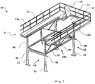
- FIG. 1 is a perspective view of an overhead conveyor 01 outlined in exemplary embodiment. In this case, however, has been dispensed with the representation of belonging to the overhead conveyor 01 conveyor. This is, as the skilled person can easily understand, in the middle of the support frame 03 and this is depending on the embodiment of raised above the support frame 03 on. The arrangement of the conveyor is also off Fig. 7 seen.
- the support frame 03 consists of two successively arranged support frame modules 03a and 03b.
- the support frame modules 03a and 03b are each designed in the manner of a truss and include a Plurality of stringer elements 04-07 welded together. As for this from the FIG.
- the support frame modules 03a and 03b of longitudinal support beam elements 04, transverse support beam elements 05, upright support beam elements 06 and diagonal support beam elements 07 are formed.
- the support frame modules 03a and 03b with the support beam elements 04, 05, 06 and 07 are in this case designed such that with mounted conveyor sufficient self-supporting rigidity is present, so that a transport of the entire overhead conveyor 01 or at least individual support frame modules 03a or 3b with mounted on conveyor possible is.
- the support frame modules 03a and 03b are each assembled from two side parts 49 and 50 and a bottom part 51.
- the side parts 49 and 50 and the bottom part 51 have a respective planar component structure with high rigidity in the component plane.
- the side parts 49 and 50 and the bottom part 51 are composed of the support beam elements 04, 05, 06 and 07.
- the support frame 03 is to be interpreted in terms of rigidity, in particular bending stiffness to the effect that storage for the transport case as well as for later installation on the associated column portals 48 is substantially free of deformation possible.
- the supporting frame 03 is mounted on a plurality of column gantries 48.
- Each pillar gantry 48 consists of at least two support columns 21 and a transverse bridge 08 mounted therebetween.
- the statics of the support frame 03 are designed and the rigidity chosen such that the stability of the entire arrangement is ensured even if individual support columns are omitted.
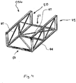
- Fig. 5 shows a second exemplary overhead conveyor 52, whose structure is derived from the overhead conveyor 01.
- the overhead conveyor 52 consists of the input support frame module 03a and the output support frame module 03b, which are already used for the production of the overhead conveyor 01 use.
- the overhead conveyor 51 includes an intermediate shoring module 03c to thereby correspondingly increase the length of the overhead conveyor.
- the individual support frame modules 03a, 03b and 03c are connected to each other in the intermediate levels 53 and 54 by means of fastening devices.
- the respective adjacent support frame modules 03a, 03b and 03c lie together on a respective pillar portal 48.
- compensation elements arranged to dampen vibrations and reduce thermal stresses.
- Fig. 6 shows a third exemplary overhead conveyor 55 derived from the shoring module 52.
- the support frame module 55 For the production of the support frame module 55, an input support frame module 03a, an output support frame module 03b and two identical intermediate support frame modules 03c are combined with each other and arranged one behind the other.
- the mass produced two intermediate support frame modules 03c are substantially identical and can thus be produced very inexpensively in series.
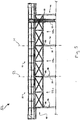
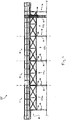
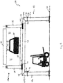
- Fig. 7 shows a second overhead conveyor 30 in front view.
- the overhead conveyor 30 is provided for transporting vehicle components 31 along a conveyor corridor 32.
- the actual conveying movement for transporting the vehicle components 31 is thereby applied by a conveying device 33, for example a push conveyor.
- the conveyor 33 is attached to the vehicle components 31 with coupling members 34.
- the conveyor 33 in turn is placed on the sides of two side panels 35 and 36 and fixed.
- the side parts 35 and 36 are connected to each other below the conveyor corridor 32 by a bottom part 37.
- the two side parts 35 and 36 and the bottom part 37 together form a support frame 38, which has a U-shaped channel shape and the conveyor corridor 32 each bounded laterally and from below.
- the support frame 38 consists of successively arranged support frame modules 38a and 38b (in Fig.
- the shoring modules 38a and 38b can be transported in preassembled form from a place of manufacture to the place of use.
- the self-supporting carrying frame 38 is placed and secured for the production of the overhead conveyor 30 from above on a plurality of pillar portals 39 arranged one behind the other.
- Each pillar gantry consists of two support columns 40 and 41 and a cross-bridge 42 mounted between the two support columns 40 and 41. Attachment tabs 43 and 44 are provided at the lower ends of the side members 35 and 36 and at the top of the transverse bridge 42, respectively Support frame 38 on the column gantries 39 and a subsequent fixation allow.
- the support columns 40 and 41 and the transverse bridge 42 are made of rectangular tubes and have at their adjacent ends in each case a miter cut, so that the end cross sections of the two support columns are flush with the end cross sections of the transverse bridge to the plant.
- the mitered end cross-sections are welded together with welds 45.
- connection points 46 are provided on the support columns 40 and 41, in which the support columns 40 and 41 can be disassembled into two parts 40a and 40b or 41a and 41b.
Landscapes
- Engineering & Computer Science (AREA)
- Mechanical Engineering (AREA)
- Manufacturing & Machinery (AREA)
- Chemical & Material Sciences (AREA)
- Combustion & Propulsion (AREA)
- Transportation (AREA)
- Automatic Assembly (AREA)
- Automobile Manufacture Line, Endless Track Vehicle, Trailer (AREA)
- Body Structure For Vehicles (AREA)
- Intermediate Stations On Conveyors (AREA)
- Mounting Of Bearings Or Others (AREA)
- Fittings On The Vehicle Exterior For Carrying Loads, And Devices For Holding Or Mounting Articles (AREA)
- Warehouses Or Storage Devices (AREA)
Claims (13)
- Dispositif (01, 30, 52, 55) de convoyeur aérien pour être intégré dans une usine d'assemblage pour transporter des composants (31) de véhicule au moyen d'un dispositif (33) de convoyeur qui est disposé sur le dispositif (01, 30, 52, 55) de convoyeur aérien, ledit dispositif de convoyeur aérien comprenant un cadre (03, 38) de support, ledit cadre (03, 38) de support ayant une longueur de plus de 5 m et une largeur de plus de 2 m, et ledit dispositif (33) de convoyeur pouvant être monté sur le cadre (03, 38) de support, et ledit cadre (03, 38) de support et ledit dispositif (33) de convoyeur formant un couloir (32) de convoyeur dans lequel les composants (31) de véhicule peuvent être transportés d'un point d'entrée vers un point de sortie, et ledit cadre (03, 38) de support étant monté au-dessus du fond (47) de l'usine d'assemblage par des moyens (39, 48) d'appui, et lesdits moyens (39, 48) d'appui occasionnant la formation, entre le côté inférieur du cadre (03, 38) de support et le côté supérieur du fond (47), d'un espace libre qui est approprié pour l'assemblage des composants et/ou pour le transport des composants et qui est accessible à pied et/ou par véhicule, dans lequel
le cadre (03, 38) de support est formé d'au moins deux modules (03a, 03b, 03c, 38a, 38b) de cadre de support qui sont disposés l'un derrière l'autre dans la direction du couloir (32) de convoyeur,
caractérisé en ce que
les modules (03a, 03b, 03c, 38a, 38b) de cadre de support sont réalisés à la manière d'un colombage spatial qui comporte des éléments (04, 05, 06, 07) de poutre de support orientés longitudinalement et transversalement et interconnectés diagonalement et verticalement, lesdits éléments (04, 05, 06, 07) de poutre de support présentant une coupe transversale tubulaire fermée. - Dispositif de convoyeur aérien selon la revendication 1,
caractérisé en ce que
les modules (03a, 03b, 03c, 38a, 38b) de cadre de support, à la jonction avec des modules (03a, 03b, 03c, 38a, 38b) de cadre de support adjacents, présentent des dispositifs de fixation qui permettent la liaison de modules (03a, 03b, 03c, 38a, 38b) de cadre de support adjacents. - Dispositif de convoyeur aérien selon la revendication 1 ou 2,
caractérisé en ce que
le dispositif (01, 30, 52, 55) de convoyeur aérien présente un module (03a, 38a) de cadre de support d'entrée, le point d'entrée pour les composants (31) de véhicule étant prévu sur ledit module de cadre de support d'entrée, et un module (03b, 38b) de cadre de support de sortie, le point de sortie pour les composants (31) de véhicule étant prévu sur ledit module de cadre de support de sortie. - Dispositif de convoyeur aérien selon la revendication 3,
caractérisé en ce qu'
un module (03c) de cadre de support intermédiaire est prévu entre le module (03a) de cadre de support d'entrée et le module (03b) de cadre de support de sortie. - Dispositif de convoyeur aérien selon la revendication 4,
caractérisé en ce que
le dispositif (55) de convoyeur aérien comporte plusieurs modules (03c) de cadre de support intermédiaires, lesdits modules (03c) de cadre de support intermédiaires étant réalisés essentiellement de construction identique. - Dispositif de convoyeur aérien selon l'une quelconque des revendications 1 à 5,
caractérisé en ce que
des éléments de compensation sont disposés entre des modules (03a, 03b, 03c, 38a, 38b) de cadre de support adjacents, des vibrations entre les modules de cadre de support pouvant être atténuées et/ou des contraintes thermiques pouvant être baissées par lesdits éléments de compensation. - Dispositif de convoyeur aérien selon l'une quelconque des revendications 1 à 6,
caractérisé en ce que
sur au moins un module (03a, 03b, 03c, 38a, 38b) de cadre de support, un moyen d'appui à la manière d'un portique de colonne (39, 48) est prévu, ledit portique de colonne (39, 48) comportant au moins deux colonnes (21, 40, 41) de support dont les extrémités inférieures sont montées au fond (47) de l'usine d'assemblage, et au moins un pont transversal (08, 42) étant monté entre les deux colonnes de support (21, 40, 41), et ledit module (03a, 03b, 03c, 38a, 38b) de cadre de support étant disposé sur le côté supérieur du pont transversal. - Dispositif de convoyeur aérien selon l'une quelconque des revendications 1 à 7,
caractérisé en ce que
les modules (03a, 03b, 03c, 38a, 38b) de cadre de support sont réalisés de manière autoportante et peuvent être transportés dans une forme préassemblée. - Dispositif de convoyeur aérien selon l'une quelconque des revendications 1 à 8,
caractérisé en ce que
les modules (03a, 03b, 03c, 38a, 38b) de cadre de support comportent au moins deux pièces latérales (35, 36, 49, 50) qui s'étendent en parallèle par rapport à l'axe longitudinal du couloir (32) de convoyeur et limitent la coupe transversale du couloir (32) de convoyeur à droite et à gauche. - Dispositif de convoyeur aérien selon l'une quelconque des revendications 1 à 9,
caractérisé en ce que
le dispositif (33) de convoyeur peut être monté entre les deux pièces latérales (35, 36, 49, 50) et limite la coupe transversale du couloir (32) de convoyeur par le haut. - Dispositif de convoyeur aérien selon l'une quelconque des revendications 1 à 10,
caractérisé en ce que
les modules (03a, 03b, 03c, 38a, 38b) de cadre de support chacun comportent au moins une pièce (37, 51) de fond qui limite la coupe transversale du couloir (32) de convoyeur par le bas. - Dispositif de convoyeur aérien selon l'une quelconque des revendications 1 à 11,
caractérisé en ce qu'
un couloir de service est monté à au moins un module (03a, 03b, 03c, 38a, 38b) de cadre de support, le long du côté longitudinal du dispositif (33) de convoyeur. - Dispositif de convoyeur aérien selon l'une quelconque des revendications 1 à 12,
caractérisé en ce que
les modules (03a, 03b, 03c, 38a, 38b) de cadre de support sont formés par une construction de soudure.
Priority Applications (1)
| Application Number | Priority Date | Filing Date | Title |
|---|---|---|---|
| PL14730442T PL3016843T3 (pl) | 2013-07-05 | 2014-05-22 | Nadziemne urządzenie przenośnikowe z modułami podpory nośnej |
Applications Claiming Priority (2)
| Application Number | Priority Date | Filing Date | Title |
|---|---|---|---|
| DE102013213222.0A DE102013213222A1 (de) | 2013-07-05 | 2013-07-05 | Überflurfördereinrichtung mit Traggerüstmodulen |
| PCT/EP2014/060533 WO2015000635A1 (fr) | 2013-07-05 | 2014-05-22 | Convoyeur aérien équipé de modules de châssis porteur |
Publications (2)
| Publication Number | Publication Date |
|---|---|
| EP3016843A1 EP3016843A1 (fr) | 2016-05-11 |
| EP3016843B1 true EP3016843B1 (fr) | 2018-11-28 |
Family
ID=50943280
Family Applications (1)
| Application Number | Title | Priority Date | Filing Date |
|---|---|---|---|
| EP14730442.2A Not-in-force EP3016843B1 (fr) | 2013-07-05 | 2014-05-22 | Convoyeur aérien équipé de modules de châssis porteur |
Country Status (14)
| Country | Link |
|---|---|
| US (1) | US9908575B2 (fr) |
| EP (1) | EP3016843B1 (fr) |
| JP (2) | JP2016530145A (fr) |
| KR (1) | KR101969628B1 (fr) |
| CN (1) | CN105358415B (fr) |
| CA (1) | CA2922782C (fr) |
| DE (1) | DE102013213222A1 (fr) |
| ES (1) | ES2710534T3 (fr) |
| HU (1) | HUE043887T2 (fr) |
| MX (1) | MX366259B (fr) |
| PL (1) | PL3016843T3 (fr) |
| RU (1) | RU2651946C2 (fr) |
| TR (1) | TR201820851T4 (fr) |
| WO (1) | WO2015000635A1 (fr) |
Families Citing this family (6)
| Publication number | Priority date | Publication date | Assignee | Title |
|---|---|---|---|---|
| US10239702B2 (en) | 2017-01-06 | 2019-03-26 | Roach Manufacturing Corporation | Tubular mezzanine and conveyor support structures and stiffener brackets for assembly thereof |
| DE102017100450A1 (de) * | 2017-01-11 | 2018-07-12 | Torsten Hösker | Überflurfördereinrichtung mit vertikal angeordneter Fördereinrichtung |
| DE102017101908A1 (de) * | 2017-01-31 | 2018-08-02 | Dürr Assembly Products GmbH | Elemente einer Fertigungsstraße für Kraftfahrzeuge |
| CN110550412B (zh) * | 2019-09-19 | 2024-04-02 | 驭势科技(浙江)有限公司 | 智能驾驶运输工具、运输工具组合及控制方法 |
| CN114012427B (zh) * | 2021-11-05 | 2024-02-23 | 安徽森泰木塑集团股份有限公司 | 一种围栏生产线及生产方法 |
| CN114044356B (zh) * | 2021-11-11 | 2023-04-07 | 中铁二十三局集团轨道交通四川工程有限公司 | 一种盾构管片修补系统及方法 |
Citations (18)
| Publication number | Priority date | Publication date | Assignee | Title |
|---|---|---|---|---|
| DE570661C (de) | 1928-01-07 | 1933-02-18 | Franz Kruckenberg Dipl Ing | Tragwerk fuer die Fahrbahn von Haengeschnellbahnen mit sehr hohen Geschwindigkeiten |
| DE19806963A1 (de) | 1997-03-22 | 1998-10-08 | Thyssen Industrie | Verfahren und Vorrichtung zum Zuführen, Spannen und Bearbeiten, insbesondere zum Geometrie-Schweißen von Bauteilen von Fahrzeugkarosserien in einer Bearbeitungsstation |
| EP0997403A1 (fr) | 1998-10-23 | 2000-05-03 | Societe Bibaut A.D.B.R. | Système de transporteur à bande facilement déplacable, notamment pour une installation temporaire |
| DE19943889A1 (de) | 1999-09-14 | 2001-03-15 | Geisselmann Gmbh | Trägersystem |
| JP2003341818A (ja) | 2002-05-27 | 2003-12-03 | Shinichiro Shiraiwa | 車両の組み立てに関する搬送装置 |
| WO2004052715A2 (fr) | 2002-12-08 | 2004-06-24 | Dürr Aktiengesellschaft | Dispositif pour monter, regler et controler des automobiles |
| DE60202985T2 (de) | 2001-09-26 | 2006-04-13 | Nissan Motor Co., Ltd., Yokohama | Verfahren und Vorrichtung zum Zusammenbau eines Fahrzeugaufbaus |
| JP2008222137A (ja) | 2007-03-15 | 2008-09-25 | Daifuku Co Ltd | 吊下げ搬送設備 |
| JP2009012141A (ja) | 2007-07-06 | 2009-01-22 | Nakanishi Metal Works Co Ltd | 昇降機能付き吊下げ搬送車及び吊下げ台 |
| DE202009006856U1 (de) | 2009-05-12 | 2009-08-20 | Hager, Hans | Transportvorrichtung für den Transport von Gegenständen von und zu einer Arbeitsstation |
| CN201573722U (zh) | 2009-12-07 | 2010-09-08 | 江苏天奇物流系统工程股份有限公司 | 摩擦式底盘线输送系统 |
| WO2011013012A1 (fr) | 2009-07-27 | 2011-02-03 | Comau S.P.A. | Système pour emballage en caisse de carrosseries de motorisés automobiles ou de sous-ensembles de ces carrosseries |
| JP2011099313A (ja) | 2009-10-06 | 2011-05-19 | Nippon Steel Corp | コンベアー支持用の断面箱型のトラス架構 |
| EP2340982A1 (fr) | 2009-12-30 | 2011-07-06 | COMAU SpA | Installation permettant d'assembler les pièces mécaniques sur les carrosseries de véhicules à moteur |
| CN101734475B (zh) | 2009-12-07 | 2011-09-21 | 江苏天奇物流系统工程股份有限公司 | 摩擦式底盘线输送系统 |
| DE102011008623A1 (de) | 2011-01-14 | 2012-07-19 | Audi Ag | Vorrichtung zur Bereitstellung und/oder Pufferung von Bauteilen oder Baukomponenten an einer Fertigungslinie |
| DE112010000862T5 (de) | 2009-01-09 | 2012-10-11 | Caterpillar Inc. | Modulare fertigungsstrasse, die einen puffer umfasst und verfahren zum betreiben derselben |
| WO2014023277A1 (fr) | 2012-08-09 | 2014-02-13 | Hoesker Torsten | Dispositif de transport surélevé comportant une charpente porteuse auto-porteuse |
Family Cites Families (11)
| Publication number | Priority date | Publication date | Assignee | Title |
|---|---|---|---|---|
| US3156018A (en) * | 1961-12-21 | 1964-11-10 | John H Slayter | Plant-manufactured building structure |
| JPS6012509U (ja) * | 1983-07-07 | 1985-01-28 | 株式会社ダイフク | 回転ラツク装置 |
| FR2578464B1 (fr) * | 1985-03-06 | 1987-04-30 | Steelweld France | Installation d'assemblage de pieces de carrosserie de vehicule |
| US5078250A (en) * | 1991-01-07 | 1992-01-07 | Sinco, Inc. | Universal safety guard assembly for a conveyor |
| DE19641048C2 (de) * | 1996-10-04 | 2000-07-20 | Flaekt Ab | Verfahren zum Ein- und Ausbringen von Werkstücken, insbesondere Fahrzeugkarosserien, Vorrichtung und Anlage zur Oberflächenbehandlung von Werkstücken im Durchlauf |
| JP3653689B2 (ja) * | 1998-07-15 | 2005-06-02 | 清水建設株式会社 | 建物の屋根の構造 |
| KR20050098669A (ko) * | 2004-04-08 | 2005-10-12 | 현대자동차주식회사 | 위치 보정장치가 구비된 오버헤드 컨베이어 및 제어방법 |
| WO2007144635A2 (fr) * | 2006-06-14 | 2007-12-21 | Condek Holdings Limited | Structure de stationnement de véhicules |
| JP4209919B2 (ja) * | 2007-01-26 | 2009-01-14 | 本田技研工業株式会社 | ハンガー駆動装置 |
| JP2009161259A (ja) * | 2007-12-28 | 2009-07-23 | Nakanishi Metal Works Co Ltd | コンベア用自立式支持架構 |
| DE102012009061A1 (de) * | 2012-05-09 | 2013-11-14 | Thyssenkrupp System Engineering Gmbh | Bearbeitungsanlage für Baueinheiten |
-
2013
- 2013-07-05 DE DE102013213222.0A patent/DE102013213222A1/de not_active Withdrawn
-
2014
- 2014-05-22 MX MX2016000015A patent/MX366259B/es active IP Right Grant
- 2014-05-22 KR KR1020167002830A patent/KR101969628B1/ko active IP Right Grant
- 2014-05-22 PL PL14730442T patent/PL3016843T3/pl unknown
- 2014-05-22 HU HUE14730442A patent/HUE043887T2/hu unknown
- 2014-05-22 US US14/900,326 patent/US9908575B2/en not_active Expired - Fee Related
- 2014-05-22 WO PCT/EP2014/060533 patent/WO2015000635A1/fr active Application Filing
- 2014-05-22 EP EP14730442.2A patent/EP3016843B1/fr not_active Not-in-force
- 2014-05-22 CA CA2922782A patent/CA2922782C/fr not_active Expired - Fee Related
- 2014-05-22 ES ES14730442T patent/ES2710534T3/es active Active
- 2014-05-22 JP JP2016522356A patent/JP2016530145A/ja active Pending
- 2014-05-22 TR TR2018/20851T patent/TR201820851T4/tr unknown
- 2014-05-22 RU RU2016102190A patent/RU2651946C2/ru active
- 2014-05-22 CN CN201480038585.4A patent/CN105358415B/zh not_active Expired - Fee Related
-
2018
- 2018-10-09 JP JP2018191028A patent/JP6629408B2/ja not_active Expired - Fee Related
Patent Citations (19)
| Publication number | Priority date | Publication date | Assignee | Title |
|---|---|---|---|---|
| DE570661C (de) | 1928-01-07 | 1933-02-18 | Franz Kruckenberg Dipl Ing | Tragwerk fuer die Fahrbahn von Haengeschnellbahnen mit sehr hohen Geschwindigkeiten |
| DE19806963A1 (de) | 1997-03-22 | 1998-10-08 | Thyssen Industrie | Verfahren und Vorrichtung zum Zuführen, Spannen und Bearbeiten, insbesondere zum Geometrie-Schweißen von Bauteilen von Fahrzeugkarosserien in einer Bearbeitungsstation |
| EP0997403A1 (fr) | 1998-10-23 | 2000-05-03 | Societe Bibaut A.D.B.R. | Système de transporteur à bande facilement déplacable, notamment pour une installation temporaire |
| DE19943889A1 (de) | 1999-09-14 | 2001-03-15 | Geisselmann Gmbh | Trägersystem |
| DE60202985T2 (de) | 2001-09-26 | 2006-04-13 | Nissan Motor Co., Ltd., Yokohama | Verfahren und Vorrichtung zum Zusammenbau eines Fahrzeugaufbaus |
| JP2003341818A (ja) | 2002-05-27 | 2003-12-03 | Shinichiro Shiraiwa | 車両の組み立てに関する搬送装置 |
| WO2004052715A2 (fr) | 2002-12-08 | 2004-06-24 | Dürr Aktiengesellschaft | Dispositif pour monter, regler et controler des automobiles |
| JP2008222137A (ja) | 2007-03-15 | 2008-09-25 | Daifuku Co Ltd | 吊下げ搬送設備 |
| JP2009012141A (ja) | 2007-07-06 | 2009-01-22 | Nakanishi Metal Works Co Ltd | 昇降機能付き吊下げ搬送車及び吊下げ台 |
| DE112010000862T5 (de) | 2009-01-09 | 2012-10-11 | Caterpillar Inc. | Modulare fertigungsstrasse, die einen puffer umfasst und verfahren zum betreiben derselben |
| DE202009006856U1 (de) | 2009-05-12 | 2009-08-20 | Hager, Hans | Transportvorrichtung für den Transport von Gegenständen von und zu einer Arbeitsstation |
| WO2011013012A1 (fr) | 2009-07-27 | 2011-02-03 | Comau S.P.A. | Système pour emballage en caisse de carrosseries de motorisés automobiles ou de sous-ensembles de ces carrosseries |
| JP2011099313A (ja) | 2009-10-06 | 2011-05-19 | Nippon Steel Corp | コンベアー支持用の断面箱型のトラス架構 |
| CN201573722U (zh) | 2009-12-07 | 2010-09-08 | 江苏天奇物流系统工程股份有限公司 | 摩擦式底盘线输送系统 |
| CN101734475B (zh) | 2009-12-07 | 2011-09-21 | 江苏天奇物流系统工程股份有限公司 | 摩擦式底盘线输送系统 |
| EP2340982A1 (fr) | 2009-12-30 | 2011-07-06 | COMAU SpA | Installation permettant d'assembler les pièces mécaniques sur les carrosseries de véhicules à moteur |
| DE102011008623A1 (de) | 2011-01-14 | 2012-07-19 | Audi Ag | Vorrichtung zur Bereitstellung und/oder Pufferung von Bauteilen oder Baukomponenten an einer Fertigungslinie |
| WO2014023277A1 (fr) | 2012-08-09 | 2014-02-13 | Hoesker Torsten | Dispositif de transport surélevé comportant une charpente porteuse auto-porteuse |
| WO2014023273A1 (fr) | 2012-08-09 | 2014-02-13 | Hoesker Torsten | Dispositif de transport surélevé doté de portiques à colonnes |
Also Published As
| Publication number | Publication date |
|---|---|
| CA2922782C (fr) | 2018-12-11 |
| CA2922782A1 (fr) | 2015-01-08 |
| PL3016843T3 (pl) | 2019-05-31 |
| WO2015000635A1 (fr) | 2015-01-08 |
| RU2651946C2 (ru) | 2018-04-24 |
| DE102013213222A1 (de) | 2015-01-08 |
| KR20160029095A (ko) | 2016-03-14 |
| MX366259B (es) | 2019-07-02 |
| RU2016102190A (ru) | 2017-08-10 |
| US20160207579A1 (en) | 2016-07-21 |
| CN105358415A (zh) | 2016-02-24 |
| CN105358415B (zh) | 2019-05-10 |
| TR201820851T4 (tr) | 2019-01-21 |
| HUE043887T2 (hu) | 2019-09-30 |
| KR101969628B1 (ko) | 2019-08-13 |
| ES2710534T3 (es) | 2019-04-25 |
| JP2019048629A (ja) | 2019-03-28 |
| MX2016000015A (es) | 2016-08-03 |
| EP3016843A1 (fr) | 2016-05-11 |
| US9908575B2 (en) | 2018-03-06 |
| JP2016530145A (ja) | 2016-09-29 |
| JP6629408B2 (ja) | 2020-01-15 |
Similar Documents
| Publication | Publication Date | Title |
|---|---|---|
| EP3016843B1 (fr) | Convoyeur aérien équipé de modules de châssis porteur | |
| EP2882634B1 (fr) | Structure de convoyeur aerien au-dessus d'un portique | |
| EP1799603B1 (fr) | Cabine d'ascenseur modulaire | |
| EP3356277B1 (fr) | Procédé de montage d'une ossature porteuse pour une installation de transport de personnes dans un bâtiment | |
| EP2900585B1 (fr) | Système de voie pour un escalier roulant ou un trottoir roulant | |
| WO2007066228A2 (fr) | Poteau mixte destine a des raccords a goussets de batiments et structure de batiment | |
| WO2022200029A1 (fr) | Structure de support d'un escalier roulant ou d'un trottoir roulant | |
| DE102004058831B3 (de) | Hilfsrahmen für einen Fahrgestellrahmen eines Nutzfahrzeugs | |
| EP3743567B1 (fr) | Système de conteneurs variable | |
| EP3931142B1 (fr) | Zone de raccordement de la section de treillis | |
| EP3150540A1 (fr) | Procede de fabrication d'une ossature porteuse pour une installation de transport de personnes | |
| EP3049316B1 (fr) | Système de convoyeur aérien à monter au plafond d'une ligne de montage | |
| EP2316780B1 (fr) | Mât pour un transstockeur | |
| WO2006026873A1 (fr) | Cabine d'ascenseur, et son procede d'installation | |
| EP4031728B1 (fr) | Dispositif imprimante permettant de produire une structure de béton d'une installation de transport de personnes | |
| EP3296475B1 (fr) | Balcon et procédé de fabrication d'un tel balcon | |
| DE3843996A1 (de) | Mast fuer einen zahnstangenaufzug | |
| EP3150539A1 (fr) | Ossature porteuse pour une installation de transport de personnes | |
| EP3153635B1 (fr) | Composant a isolation thermique | |
| EP3049315A1 (fr) | Système de convoyeur aérien à monter au plafond d'une ligne de montage | |
| WO2019192794A1 (fr) | Dispositif de transport aérien avec liaison par collage | |
| EP3121143A1 (fr) | Élement de cadre pour une structure porteuse d'un escalier roulant ou d'un trottoir roulant | |
| EP3568340A1 (fr) | Système de convoyage aérien comprenant un convoyeur disposé verticalement | |
| CH658696A5 (en) | Steel structure for a hall | |
| EP3839172A1 (fr) | Longeron garde-corps destiné au montage d'un garde-corps avant, garde-corps avant destiné à la protection temporaire contre les chutes d'un nouvel étage d'un échafaudage à créer, échafaudage pour travaux de construction, de réparation et/ou de montage et processus de construction d'un échafaudage |
Legal Events
| Date | Code | Title | Description |
|---|---|---|---|
| PUAI | Public reference made under article 153(3) epc to a published international application that has entered the european phase |
Free format text: ORIGINAL CODE: 0009012 |
|
| 17P | Request for examination filed |
Effective date: 20160113 |
|
| AK | Designated contracting states |
Kind code of ref document: A1 Designated state(s): AL AT BE BG CH CY CZ DE DK EE ES FI FR GB GR HR HU IE IS IT LI LT LU LV MC MK MT NL NO PL PT RO RS SE SI SK SM TR |
|
| AX | Request for extension of the european patent |
Extension state: BA ME |
|
| DAX | Request for extension of the european patent (deleted) | ||
| REG | Reference to a national code |
Ref country code: DE Ref legal event code: R079 Ref document number: 502014010216 Country of ref document: DE Free format text: PREVIOUS MAIN CLASS: B62D0065180000 Ipc: B65G0041000000 |
|
| GRAP | Despatch of communication of intention to grant a patent |
Free format text: ORIGINAL CODE: EPIDOSNIGR1 |
|
| STAA | Information on the status of an ep patent application or granted ep patent |
Free format text: STATUS: GRANT OF PATENT IS INTENDED |
|
| RIC1 | Information provided on ipc code assigned before grant |
Ipc: B65G 41/00 20060101AFI20180615BHEP Ipc: B62D 65/18 20060101ALI20180615BHEP |
|
| INTG | Intention to grant announced |
Effective date: 20180704 |
|
| GRAS | Grant fee paid |
Free format text: ORIGINAL CODE: EPIDOSNIGR3 |
|
| GRAA | (expected) grant |
Free format text: ORIGINAL CODE: 0009210 |
|
| STAA | Information on the status of an ep patent application or granted ep patent |
Free format text: STATUS: THE PATENT HAS BEEN GRANTED |
|
| AK | Designated contracting states |
Kind code of ref document: B1 Designated state(s): AL AT BE BG CH CY CZ DE DK EE ES FI FR GB GR HR HU IE IS IT LI LT LU LV MC MK MT NL NO PL PT RO RS SE SI SK SM TR |
|
| REG | Reference to a national code |
Ref country code: CH Ref legal event code: EP |
|
| REG | Reference to a national code |
Ref country code: AT Ref legal event code: REF Ref document number: 1069984 Country of ref document: AT Kind code of ref document: T Effective date: 20181215 |
|
| REG | Reference to a national code |
Ref country code: DE Ref legal event code: R096 Ref document number: 502014010216 Country of ref document: DE |
|
| REG | Reference to a national code |
Ref country code: IE Ref legal event code: FG4D Free format text: LANGUAGE OF EP DOCUMENT: GERMAN |
|
| REG | Reference to a national code |
Ref country code: RO Ref legal event code: EPE |
|
| REG | Reference to a national code |
Ref country code: NL Ref legal event code: FP |
|
| REG | Reference to a national code |
Ref country code: SE Ref legal event code: TRGR |
|
| REG | Reference to a national code |
Ref country code: LT Ref legal event code: MG4D |
|
| REG | Reference to a national code |
Ref country code: ES Ref legal event code: FG2A Ref document number: 2710534 Country of ref document: ES Kind code of ref document: T3 Effective date: 20190425 |
|
| PG25 | Lapsed in a contracting state [announced via postgrant information from national office to epo] |
Ref country code: IS Free format text: LAPSE BECAUSE OF FAILURE TO SUBMIT A TRANSLATION OF THE DESCRIPTION OR TO PAY THE FEE WITHIN THE PRESCRIBED TIME-LIMIT Effective date: 20190328 Ref country code: BG Free format text: LAPSE BECAUSE OF FAILURE TO SUBMIT A TRANSLATION OF THE DESCRIPTION OR TO PAY THE FEE WITHIN THE PRESCRIBED TIME-LIMIT Effective date: 20190228 Ref country code: LT Free format text: LAPSE BECAUSE OF FAILURE TO SUBMIT A TRANSLATION OF THE DESCRIPTION OR TO PAY THE FEE WITHIN THE PRESCRIBED TIME-LIMIT Effective date: 20181128 Ref country code: HR Free format text: LAPSE BECAUSE OF FAILURE TO SUBMIT A TRANSLATION OF THE DESCRIPTION OR TO PAY THE FEE WITHIN THE PRESCRIBED TIME-LIMIT Effective date: 20181128 Ref country code: LV Free format text: LAPSE BECAUSE OF FAILURE TO SUBMIT A TRANSLATION OF THE DESCRIPTION OR TO PAY THE FEE WITHIN THE PRESCRIBED TIME-LIMIT Effective date: 20181128 Ref country code: NO Free format text: LAPSE BECAUSE OF FAILURE TO SUBMIT A TRANSLATION OF THE DESCRIPTION OR TO PAY THE FEE WITHIN THE PRESCRIBED TIME-LIMIT Effective date: 20190228 Ref country code: FI Free format text: LAPSE BECAUSE OF FAILURE TO SUBMIT A TRANSLATION OF THE DESCRIPTION OR TO PAY THE FEE WITHIN THE PRESCRIBED TIME-LIMIT Effective date: 20181128 |
|
| PG25 | Lapsed in a contracting state [announced via postgrant information from national office to epo] |
Ref country code: AL Free format text: LAPSE BECAUSE OF FAILURE TO SUBMIT A TRANSLATION OF THE DESCRIPTION OR TO PAY THE FEE WITHIN THE PRESCRIBED TIME-LIMIT Effective date: 20181128 Ref country code: PT Free format text: LAPSE BECAUSE OF FAILURE TO SUBMIT A TRANSLATION OF THE DESCRIPTION OR TO PAY THE FEE WITHIN THE PRESCRIBED TIME-LIMIT Effective date: 20190328 Ref country code: RS Free format text: LAPSE BECAUSE OF FAILURE TO SUBMIT A TRANSLATION OF THE DESCRIPTION OR TO PAY THE FEE WITHIN THE PRESCRIBED TIME-LIMIT Effective date: 20181128 Ref country code: GR Free format text: LAPSE BECAUSE OF FAILURE TO SUBMIT A TRANSLATION OF THE DESCRIPTION OR TO PAY THE FEE WITHIN THE PRESCRIBED TIME-LIMIT Effective date: 20190301 |
|
| REG | Reference to a national code |
Ref country code: SK Ref legal event code: T3 Ref document number: E 30105 Country of ref document: SK |
|
| PGFP | Annual fee paid to national office [announced via postgrant information from national office to epo] |
Ref country code: NL Payment date: 20190521 Year of fee payment: 6 |
|
| PG25 | Lapsed in a contracting state [announced via postgrant information from national office to epo] |
Ref country code: DK Free format text: LAPSE BECAUSE OF FAILURE TO SUBMIT A TRANSLATION OF THE DESCRIPTION OR TO PAY THE FEE WITHIN THE PRESCRIBED TIME-LIMIT Effective date: 20181128 |
|
| PGFP | Annual fee paid to national office [announced via postgrant information from national office to epo] |
Ref country code: IT Payment date: 20190521 Year of fee payment: 6 Ref country code: CZ Payment date: 20190515 Year of fee payment: 6 Ref country code: PL Payment date: 20190418 Year of fee payment: 6 Ref country code: ES Payment date: 20190619 Year of fee payment: 6 |
|
| REG | Reference to a national code |
Ref country code: DE Ref legal event code: R026 Ref document number: 502014010216 Country of ref document: DE |
|
| PG25 | Lapsed in a contracting state [announced via postgrant information from national office to epo] |
Ref country code: SM Free format text: LAPSE BECAUSE OF FAILURE TO SUBMIT A TRANSLATION OF THE DESCRIPTION OR TO PAY THE FEE WITHIN THE PRESCRIBED TIME-LIMIT Effective date: 20181128 Ref country code: EE Free format text: LAPSE BECAUSE OF FAILURE TO SUBMIT A TRANSLATION OF THE DESCRIPTION OR TO PAY THE FEE WITHIN THE PRESCRIBED TIME-LIMIT Effective date: 20181128 |
|
| PGFP | Annual fee paid to national office [announced via postgrant information from national office to epo] |
Ref country code: FR Payment date: 20190521 Year of fee payment: 6 Ref country code: BE Payment date: 20190521 Year of fee payment: 6 Ref country code: TR Payment date: 20190514 Year of fee payment: 6 Ref country code: SE Payment date: 20190523 Year of fee payment: 6 Ref country code: HU Payment date: 20190510 Year of fee payment: 6 Ref country code: RO Payment date: 20190514 Year of fee payment: 6 |
|
| PLBI | Opposition filed |
Free format text: ORIGINAL CODE: 0009260 |
|
| PLAX | Notice of opposition and request to file observation + time limit sent |
Free format text: ORIGINAL CODE: EPIDOSNOBS2 |
|
| PGFP | Annual fee paid to national office [announced via postgrant information from national office to epo] |
Ref country code: SK Payment date: 20190513 Year of fee payment: 6 |
|
| REG | Reference to a national code |
Ref country code: HU Ref legal event code: AG4A Ref document number: E043887 Country of ref document: HU |
|
| 26 | Opposition filed |
Opponent name: BAIER, MARTIN Effective date: 20190828 |
|
| PG25 | Lapsed in a contracting state [announced via postgrant information from national office to epo] |
Ref country code: SI Free format text: LAPSE BECAUSE OF FAILURE TO SUBMIT A TRANSLATION OF THE DESCRIPTION OR TO PAY THE FEE WITHIN THE PRESCRIBED TIME-LIMIT Effective date: 20181128 |
|
| PGFP | Annual fee paid to national office [announced via postgrant information from national office to epo] |
Ref country code: AT Payment date: 20190517 Year of fee payment: 6 Ref country code: GB Payment date: 20190523 Year of fee payment: 6 |
|
| REG | Reference to a national code |
Ref country code: CH Ref legal event code: PL |
|
| PLBB | Reply of patent proprietor to notice(s) of opposition received |
Free format text: ORIGINAL CODE: EPIDOSNOBS3 |
|
| PG25 | Lapsed in a contracting state [announced via postgrant information from national office to epo] |
Ref country code: LI Free format text: LAPSE BECAUSE OF NON-PAYMENT OF DUE FEES Effective date: 20190531 Ref country code: MC Free format text: LAPSE BECAUSE OF FAILURE TO SUBMIT A TRANSLATION OF THE DESCRIPTION OR TO PAY THE FEE WITHIN THE PRESCRIBED TIME-LIMIT Effective date: 20181128 Ref country code: CH Free format text: LAPSE BECAUSE OF NON-PAYMENT OF DUE FEES Effective date: 20190531 |
|
| PG25 | Lapsed in a contracting state [announced via postgrant information from national office to epo] |
Ref country code: LU Free format text: LAPSE BECAUSE OF NON-PAYMENT OF DUE FEES Effective date: 20190522 |
|
| PG25 | Lapsed in a contracting state [announced via postgrant information from national office to epo] |
Ref country code: IE Free format text: LAPSE BECAUSE OF NON-PAYMENT OF DUE FEES Effective date: 20190522 |
|
| REG | Reference to a national code |
Ref country code: NL Ref legal event code: MM Effective date: 20200601 |
|
| REG | Reference to a national code |
Ref country code: AT Ref legal event code: MM01 Ref document number: 1069984 Country of ref document: AT Kind code of ref document: T Effective date: 20200522 |
|
| REG | Reference to a national code |
Ref country code: SK Ref legal event code: MM4A Ref document number: E 30105 Country of ref document: SK Effective date: 20200522 |
|
| PG25 | Lapsed in a contracting state [announced via postgrant information from national office to epo] |
Ref country code: SE Free format text: LAPSE BECAUSE OF NON-PAYMENT OF DUE FEES Effective date: 20200523 Ref country code: RO Free format text: LAPSE BECAUSE OF NON-PAYMENT OF DUE FEES Effective date: 20200522 Ref country code: HU Free format text: LAPSE BECAUSE OF NON-PAYMENT OF DUE FEES Effective date: 20200523 Ref country code: CZ Free format text: LAPSE BECAUSE OF NON-PAYMENT OF DUE FEES Effective date: 20200522 Ref country code: AT Free format text: LAPSE BECAUSE OF NON-PAYMENT OF DUE FEES Effective date: 20200522 |
|
| PG25 | Lapsed in a contracting state [announced via postgrant information from national office to epo] |
Ref country code: SK Free format text: LAPSE BECAUSE OF NON-PAYMENT OF DUE FEES Effective date: 20200522 Ref country code: NL Free format text: LAPSE BECAUSE OF NON-PAYMENT OF DUE FEES Effective date: 20200601 |
|
| PLCK | Communication despatched that opposition was rejected |
Free format text: ORIGINAL CODE: EPIDOSNREJ1 |
|
| REG | Reference to a national code |
Ref country code: BE Ref legal event code: MM Effective date: 20200531 |
|
| GBPC | Gb: european patent ceased through non-payment of renewal fee |
Effective date: 20200522 |
|
| PG25 | Lapsed in a contracting state [announced via postgrant information from national office to epo] |
Ref country code: GB Free format text: LAPSE BECAUSE OF NON-PAYMENT OF DUE FEES Effective date: 20200522 Ref country code: FR Free format text: LAPSE BECAUSE OF NON-PAYMENT OF DUE FEES Effective date: 20200531 |
|
| APAH | Appeal reference modified |
Free format text: ORIGINAL CODE: EPIDOSCREFNO |
|
| APBM | Appeal reference recorded |
Free format text: ORIGINAL CODE: EPIDOSNREFNO |
|
| APBP | Date of receipt of notice of appeal recorded |
Free format text: ORIGINAL CODE: EPIDOSNNOA2O |
|
| PG25 | Lapsed in a contracting state [announced via postgrant information from national office to epo] |
Ref country code: CY Free format text: LAPSE BECAUSE OF FAILURE TO SUBMIT A TRANSLATION OF THE DESCRIPTION OR TO PAY THE FEE WITHIN THE PRESCRIBED TIME-LIMIT Effective date: 20181128 Ref country code: BE Free format text: LAPSE BECAUSE OF NON-PAYMENT OF DUE FEES Effective date: 20200531 |
|
| APBQ | Date of receipt of statement of grounds of appeal recorded |
Free format text: ORIGINAL CODE: EPIDOSNNOA3O |
|
| PG25 | Lapsed in a contracting state [announced via postgrant information from national office to epo] |
Ref country code: MT Free format text: LAPSE BECAUSE OF FAILURE TO SUBMIT A TRANSLATION OF THE DESCRIPTION OR TO PAY THE FEE WITHIN THE PRESCRIBED TIME-LIMIT Effective date: 20181128 |
|
| REG | Reference to a national code |
Ref country code: ES Ref legal event code: FD2A Effective date: 20211001 |
|
| PG25 | Lapsed in a contracting state [announced via postgrant information from national office to epo] |
Ref country code: IT Free format text: LAPSE BECAUSE OF NON-PAYMENT OF DUE FEES Effective date: 20200522 |
|
| PG25 | Lapsed in a contracting state [announced via postgrant information from national office to epo] |
Ref country code: ES Free format text: LAPSE BECAUSE OF NON-PAYMENT OF DUE FEES Effective date: 20200523 |
|
| PGFP | Annual fee paid to national office [announced via postgrant information from national office to epo] |
Ref country code: DE Payment date: 20210721 Year of fee payment: 8 |
|
| PG25 | Lapsed in a contracting state [announced via postgrant information from national office to epo] |
Ref country code: TR Free format text: LAPSE BECAUSE OF NON-PAYMENT OF DUE FEES Effective date: 20200522 Ref country code: MK Free format text: LAPSE BECAUSE OF FAILURE TO SUBMIT A TRANSLATION OF THE DESCRIPTION OR TO PAY THE FEE WITHIN THE PRESCRIBED TIME-LIMIT Effective date: 20181128 |
|
| PG25 | Lapsed in a contracting state [announced via postgrant information from national office to epo] |
Ref country code: PL Free format text: LAPSE BECAUSE OF NON-PAYMENT OF DUE FEES Effective date: 20200522 |
|
| REG | Reference to a national code |
Ref country code: DE Ref legal event code: R119 Ref document number: 502014010216 Country of ref document: DE |
|
| APBY | Invitation to file observations in appeal sent |
Free format text: ORIGINAL CODE: EPIDOSNOBA2O |
|
| REG | Reference to a national code |
Ref country code: CH Ref legal event code: PK Free format text: BERICHTIGUNGEN |
|
| RAP4 | Party data changed (patent owner data changed or rights of a patent transferred) |
Owner name: HOESKER, TORSTEN |
|
| RIN2 | Information on inventor provided after grant (corrected) |
Inventor name: HOESKER, TORSTEN |
|
| PG25 | Lapsed in a contracting state [announced via postgrant information from national office to epo] |
Ref country code: DE Free format text: LAPSE BECAUSE OF NON-PAYMENT OF DUE FEES Effective date: 20221201 |
|
| APBU | Appeal procedure closed |
Free format text: ORIGINAL CODE: EPIDOSNNOA9O |
|
| REG | Reference to a national code |
Ref country code: DE Ref legal event code: R100 Ref document number: 502014010216 Country of ref document: DE |
|
| PLBN | Opposition rejected |
Free format text: ORIGINAL CODE: 0009273 |
|
| STAA | Information on the status of an ep patent application or granted ep patent |
Free format text: STATUS: OPPOSITION REJECTED |
|
| 27O | Opposition rejected |
Effective date: 20230629 |