EP3150539A1 - Ossature porteuse pour une installation de transport de personnes - Google Patents
Ossature porteuse pour une installation de transport de personnes Download PDFInfo
- Publication number
- EP3150539A1 EP3150539A1 EP15187455.9A EP15187455A EP3150539A1 EP 3150539 A1 EP3150539 A1 EP 3150539A1 EP 15187455 A EP15187455 A EP 15187455A EP 3150539 A1 EP3150539 A1 EP 3150539A1
- Authority
- EP
- European Patent Office
- Prior art keywords
- components
- truss
- supporting structure
- structure according
- connection openings
- Prior art date
- Legal status (The legal status is an assumption and is not a legal conclusion. Google has not performed a legal analysis and makes no representation as to the accuracy of the status listed.)
- Withdrawn
Links
Images
Classifications
-
- B—PERFORMING OPERATIONS; TRANSPORTING
- B66—HOISTING; LIFTING; HAULING
- B66B—ELEVATORS; ESCALATORS OR MOVING WALKWAYS
- B66B23/00—Component parts of escalators or moving walkways
Definitions
- the present invention relates to a structure for a passenger transport system such as an escalator, a moving walk etc.
- Passenger transport facilities are used to transport people, for example, in buildings between different height levels or within a constant height level.
- escalators which are sometimes referred to as escalators, used to transport people, for example, in a building from one floor to another floor.
- Moving walkways can be used to convey people, for example, within a floor in a horizontal plane or only a slightly inclined plane.
- Escalators and moving walks generally have a load-bearing structure called a supporting structure.
- the structure is designed to absorb forces acting on the passenger transport system during the transport of persons, in particular weight forces, and to forward them, for example, to supporting structures of the building receiving the passenger transport installation.
- suitable bearing points can be provided on the building.
- the structure may extend over two or more levels or floors of the structure and / or over shorter or longer distances within a constant floor within the building.
- a supported in the mounted state at the bearing points of the building structure can accommodate both movable and stationary arranged components of the passenger transport system.
- such components may be formed, for example, as a stepped belt, pallet belt, deflection axles, drive shafts, drive motor, transmission, control, monitoring system, security system, balustrades, comb plates, bearings, raceway and / or guide rails.
- structures for passenger transport systems are designed as truss structures.
- Such truss structures are traditionally already at the manufacturer manufactured as a whole unit or divided into several structural modules.
- the structure, which is pre-assembled as a complete unit or subdivided into several modules, is then transported to and assembled in the building in which the passenger transport system is to be installed.
- a truss forming the framework is generally composed of a plurality of rod-shaped truss components. In order to ensure sufficient stability and load carrying capacity of the structure, the individual truss components must be connected by connections of sufficiently high strength. Traditionally, trusses for structures or structural modules are usually made by conventionally welding together a plurality of sectional steel elements of different cross-sectional area and cross-sectional shape.
- a structure for a passenger transport system which can be assembled easily, inexpensively and / or with high precision.
- a structure for a passenger transportation system which can be assembled on site within a structure near a position where the passenger transportation system is to be installed.
- a structure for a passenger transport system has a framework of interconnected load-bearing truss components.
- truss components may include, for example, so-called upper straps and lower straps and these straps interconnecting transverse struts, diagonal braces and / or posts.
- With uprights timbered components are referred to connect a top chord with a bottom chord, specify the parallel distance of top chord and bottom chord and usually extend to the shortest possible distance between the two. Since their longitudinal extent is thus arranged mostly orthogonal to the upper and lower chords, they are particularly suitable that connection points for other components of the escalator or the moving walk are arranged on the uprights.
- connecting openings are formed.
- the truss components are interconnected by means of load-bearing connector components passing through connection openings of at least two adjacent truss components.
- the connector components are designed and mounted in such a way that they fill the connecting openings through which they pass through completely and without play, thereby positioning them relative to one another.
- framework structures for structures of a passenger transport system have been produced mostly by welding suitably designed truss components. Welding a variety of truss components together requires a lot of time and effort. Since the structure is a safety-relevant component, welded seams used in this case may normally only be executed by well-trained, state-certified experts. Furthermore, in general, large gauges are required for the manufacture of such welded constructions, and the effect of heat during welding usually requires straightening of the finished component. Furthermore, for a transport prefabricated at a manufacturer entire structure or individual structural modules towards a building and into the building in, in which the passenger transport system is to be installed, a considerable effort and therefore considerable costs.
- truss component-forming bars are connected together using screw-on nodes. This should be possible to produce as distortion-free framework.
- the disclosed truss must be laboriously constructed using gauges because the individual fasteners in a plane have too many degrees of freedom due to the existing play.
- the fasteners pose a security risk, since the screws used in this case can be solved by clamping elements.
- the connection of the individual truss components is at least only one force fit, at least with respect to one degree of freedom, so that, for example, could be forgiven by lateral force the entire framework.
- a framework-forming load-bearing framework components similar to the last-mentioned prior art, are connected to each other without welds or at least without a major portion of the load acting on the framework load.
- a special type of mechanical connection of two or more truss components is to be used with each other.
- the special nature and properties of these compounds results mainly from the connector components used for this purpose.
- these connector components should have sufficient mechanical stability so that they can absorb the forces and loads acting on the framework at least to a predominant extent, that is to say the connector components should be designed to bear load.
- the connector components are designed to be load-bearing in such a way that they can preferably withstand at least the same loads as the truss components connected by them.
- the connector components should be designed and mounted in such a way that, during the connection of two or multiple truss components positioning them in a predeterminable manner relative to each other.
- connection openings can be formed as passage openings or holes in the respective truss component.
- the connection openings are rotationally symmetrical, in particular with a round or circular cross-section.
- a cross-sectional area of the connection openings may be, for example, between 0.1 cm 2 and 20 cm 2 , which corresponds to a diameter of approximately between 4 mm and 50 mm in the case of circular connection openings.
- all provided in the various truss components connection openings are designed the same, in particular with the same cross-sectional area and the same contour.
- a truss component are generally at least two connection openings, for example, near opposite ends of the truss component is formed.
- the individual truss components can be interconnected by means of the already mentioned load-bearing and positioning-acting connector components.
- the connector components used for this purpose are specifically designed so that they complete after assembly, that is, in a state connecting at least two half-timbered components, fill the connecting openings of the truss components to be connected by them completely and without play.
- connection openings Under a complete and play-free filling of the connection openings can be understood that outer surfaces of the connector components during assembly so on surfaces of the truss components, especially on surfaces that form an inner boundary of the connection openings, create or nestle that the connector components to the truss components and in particular are kept free of play in their connection openings in all spatial directions.
- the interconnected truss components can preferably move in any direction relative to each other due to a caused by the connector component positive locking, but at least less than 0.3mm, preferably less than 0.1mm or more preferably less than 0.03mm can move relative to each other.
- the connector components should be configured and mounted so that they connect the truss components to be connected by a positive connection in all directions.
- the positive connection should also act in directions within a plane formed by the truss components, that is to say in directions perpendicular to a longitudinal extension direction of an elongate connector component.
- the connector components to be used for the structure proposed herein differ from simple connector components conventionally used for trusses, such as glands or classic rivets.
- Such screw connections or conventional riveting usually only bring about a positive connection along a longitudinal direction of the connector component, whereas the interconnected truss components are only positively connected in directions transverse to this longitudinal direction.
- screwing or riveting such as rivet with hot or cold molded closing heads within the accessed through them connection openings always a certain lateral play.
- the connector components are designed such that they can be inserted through at least two adjoining connection openings for connecting at least two adjoining connection openings and can then be widened on a peripheral surface penetrating the connection openings in such a way that they fill connection openings completely and without play and thereby expand the expansion openings Outer surface exerts a radially outwardly acting pressure on inner edges of the connection openings.
- the connector components should preferably be designed such that they have a lateral surface which is dimensioned such that they pass through adjacent to each other arranged connecting openings of two adjacent truss components easily, that is, with a certain play, can be inserted therethrough. Subsequently, the connector components are to be deformed during further mounting such that the cross-engaging through the connecting openings lateral surface is radially expanded.
- a part of the connector components located in the connection openings should be able to be enlarged during mounting with regard to its cross-sectional area, preferably by as far as possible a plastic deformation.
- the lateral surface of the connector component By such a widening of the lateral surface of the connector component, this can completely and without clearance fill the connection openings in the assembled state, that is, the lateral surface can preferably rest over its entire circumference completely and without play on an inner boundary surface of the connection openings.
- the lateral surface is to be so greatly expanded during the assembly process that it even exerts a certain pressure outwards on inner edges of the connection openings in the radial direction. This pressure may for example result from a permanent elastic deformation of the lateral surface and / or the edges of the connection openings.
- the fully assembled connector component should be press-fitted into the associated connection opening.
- the connector components are rivets.
- a rivet is a plastically deformable, usually cylindrical connecting element, by means of which, for example, sheet metal parts can be joined together.
- a rivet can be used to produce a rivet connection of two components that is positive in the longitudinal direction of the rivet.
- Rivets may typically be made of metals such as steel, copper, brass, aluminum alloys, or titanium or the like, optionally also made of plastics.
- blind rivet studs are a special form of rivet that only requires access to one side of the components to be joined and is typically mounted with a special blind riveter.
- a special high strength blind rivet bolt considered particularly suitable for the manufacture of a structure described herein is sold by Alcoa Fastening Systems & Rings under the name Huck BOM®. Basic principles of such a blind rivet bolt were already in US 2,527,307 described. It is also stated that when assembling such a blind rivet bolt, a sleeve-like shaft, which was previously introduced into connection openings of two components to be connected, is first radially expanded by a so-called shoulder, which has a slightly wider cross section than an inner cross section of the shaft, through the Shaft is pulled through and plastically deformed outwardly, so that the lateral surface of the shaft fits snugly against the inner surfaces of the connection openings. Only then are appropriately formed rivet heads formed by suitable plastic deformation of end regions of the shank so that the components to be connected are fixed in a form-fitting manner to one another in all spatial directions by the assembled blind rivet bolt.
- the connector components may include a sleeve and at least one received in the sleeve and relative to the sleeve have displaceable cone.
- two conical tapered cones may be received in the sleeve.
- the one cone or both cone can be displaced relative to the sleeve in such a way that the sleeve is widened outwardly from the inside in order to fill connection openings through which it passes through completely and without play and if possible to effect a press fit.
- the connector components are designed such that, after their assembly, they fill the connection openings through which they pass through completely and without play in such a way that they leave the connection openings with a tolerance of less than 0.3 mm, preferably less than 0.1 mm or more preferably less than 0,03mm, position relative to each other.
- connection openings are arranged to each other with a tolerance of less than 0.3 mm, preferably less than 0.1 mm and more preferably less than 0.03 mm, in the truss components.
- connection openings in the truss components are spatially very precisely formed and arranged.
- the "tolerance” is intended to refer to both the position at which a connection opening is arranged in a truss component, as well as their dimensions and contours.
- connection openings in the truss component to each other on the other hand Due to the positional accuracy of the connection openings in the truss component to each other on the other hand, and the positioning accuracy of the connector components on the other hand can thus be achieved that the ultimately composite truss from very precisely positioned relative to each other and connected truss components and thus can even achieve a target geometry with very low manufacturing tolerances , For example, a Framework for an entire structure for a several meters long passenger transport system with manufacturing tolerances of a few millimeters, often even just a few tenths of a millimeter, are produced.
- connection openings in the truss components can be introduced, for example, by laser cutting or water jet cutting.
- connection openings can be introduced extremely precisely into such components.
- the connection openings can furthermore be formed in an extremely reproducible manner precisely arranged in the truss components.
- connection openings can be partially formed only during assembly because they are not aligned due to the usual manufacturing tolerances otherwise, is due to the precise arrangement of the connection openings in the truss components and by the use of permanent precise positioning connector components eliminated.
- all transverse struts, diagonal struts and pillars of the truss are each of identical construction.
- the cross struts of a truss, the diagonal struts of the truss and the pillars of the truss are each geometrically identical.
- Such truss components can thus be prepared and stored as prefabricated standard parts and used if necessary for the manufacture of a structure.
- Such standard parts can be used for structures of different geometry, with an individual interpretation of the framework for a concrete structure mainly due to order specific to be produced upper and lower straps and the appropriate therein to be arranged and trainees connection openings can be achieved.
- the upper and lower chords can then be connected to each other by suitably prefabricated standard parts in the form of uniform cross struts, uniform diagonal braces and uniform uprights and thus the framework can be formed.
- the transverse struts, diagonal struts and / or uprights can be made of sheet metal or metal sheets.
- Such metal sheets can be made particularly easy by laser cutting or water jet cutting in the form, both an outer contour and to be provided in the connection openings can be formed very precisely.
- the upper and lower straps can be made in one embodiment of square tubes.
- a use of square tubes can provide sufficient mechanical load capacity of the upper and lower chords and ultimately the entire truss.
- suitable connection openings possibly again by laser cutting or water jet cutting, are introduced.
- individual truss components may be composed of several subcomponents.
- a post may be composed of a plurality of subcomponents, wherein each subcomponent is, for example, a part plate precisely cut from a metal sheet.
- the subcomponents can be connected to one another by a non-load-bearing welded connection, clinch connection or crimp connection.
- a non-load-bearing welded connection, clinch connection or crimp connection Such welding, clinching, or crimping may hold the subcomponents together at least during assembly of the framework so that assembly can be performed more easily.
- the welding, clinching or crimping connections need not be load-bearing, that is to say they need not be able to withstand the forces exerted later on the supporting structure, but can only hold the subcomponents of a truss component together during the assembly process of the truss.
- these compounds can also be carried load-bearing, if this requires the specific design.
- the truss components and / or the subcomponents of truss components may be interconnected by a non-load-bearing connector.
- Such connectors can facilitate, for example, a production or assembly of the framework and / or to facilitate positioning of the truss components during manufacture relative to one another.
- the truss components can be connected by means of connectors initially roughly positioned together or sub-components of a truss component can be roughly positioned relative to each other before the truss components and possibly their sub-components are finally mechanically stable and accurately connected by connecting using said load-bearing and positioning acting connector components ,
- Such other components may, in particular, be ribs for fastening guide rails and / or fastening areas for fastening balustrade parts and / or covering parts.
- Such measures provided for the truss components can be formed integrally with the truss components, for example by cutting their metal sheets into suitable shapes, for example to form extensions in the form of frames or attachment areas.
- frames or mounting portions may be formed as separate components and then attached to the other truss components, preferably again with load-bearing, positioning-acting connector components.
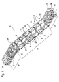
- FIG. 1 shows a supporting structure 1 for a passenger transport system.
- the structure 1 is designed as a truss 3, which can form a load-bearing structure for an escalator, by means of which persons between two floors, for example, of a building can be transported.
- the truss 3 of the structure 1 is composed of a plurality of interconnected by connector components 27 truss components 5 together.
- some of the truss components 5 mutually parallel and extending parallel to the extension direction of the elongated structure 1 upper straps 7 and 9 lower chords.
- Other truss components 5 form transverse to the upper and lower straps 7, 9 extending and connecting them cross struts 11, diagonal struts 13 and Stayers 15.
- a central region 17 of the structure 1 is inclined when it is installed as intended in a building.
- a horizontally extending likewise truss-like trained upper end portion 19 connects, which can carry an upper landing or an upper entrance area of the moving walk and in which, for example, a rail block and / or a drive space can be accommodated.
- another truss-like lower end portion 21 connects, in which, for example, a further rail block and / or a tensioning station can be accommodated.
- the supporting structure 1 in the region of a half-timbered end 35 can be connected via bearing brackets 23 to supporting structures of a structure and stored there.
- Winkelsteher 25 are provided in the truss, which connect the upper straps 7 and the lower straps 9 at a local bend of the truss 3 together.
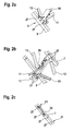
- FIGS. 2a to 2f are details of in FIG. 1 illustrated structure 1 in the marked areas A to F shown enlarged.
- FIG. 2a This shows a connection of four truss components 5, in which a post 15, a diagonal strut 13, a cross brace 11 and a lower flange 9 are firmly connected to each other by means of connector components 27.
- the uprights 15, the diagonal strut 13 and the cross strut 11 are provided in the form of cut and optionally bent metal sheet profiles, wherein at least the upright 15 is composed of several subcomponents in the form of individual in the form of various cut metal sheets.
- the lower flange 9 is formed with a square tube.
- FIG. 2b shows a further partial view of an area of the truss 3, in which a top flange 7 and a lower flange 9 are connected by means of a post 15 and diagonal struts 13 and connected by means of cross struts 11 with parallel Ober consideringtician lower straps 7, 9 (not shown).
- On the uprights 15 also bulkhead 29 are formed as a receptacle for rails. All mentioned truss components are again firmly connected by suitably stable and positioning connector components 27.
- Figure 2c shows a portion of a composite of several sub-components 31 upper or lower flange 7, 9.
- the sub-components 31 are each formed as a square tube and arranged longitudinally behind one another. At an abutting region, the two subcomponents 31 are connected to one another by means of a connecting part 33 arranged in the interior of the square tube.
- the connecting part 33 is in turn connected via stable, load-bearing and positioning connector components 27 to each of the subcomponents 31 of the upper and lower belt 7, 9. In this way, a usually several meters long top or bottom chord 7, 9 composed of several segments and, for example, does not need to be transported as a bulky unit and placed in a building.
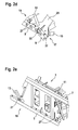
- Figure 2d shows a portion of the framework 3, in which a lower flange 9 from the central region 17 obliquely coming into another part of the lower belt 9, which in upper end portion 19 extends horizontally, passes.
- a suitably trained Winkelsteher 25 sets and connects both the inclined portion of the lower belt 9 and the horizontally extending portion of the lower belt 9 with a top flange 7 (not shown).
- parts of the lower belt 9 are supported by a correspondingly formed with a bend connecting part 33 supportive.
- the individual truss components are in turn connected to each other with load-bearing and positioning acting connector components 27.
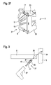
- FIG. 2e shows a partial view of the upper end portion 19 of the truss 3. Again, a variety of different truss components by means of connector components load-bearing and precisely aligned relative to each other.
- FIG. 1 shows a region of a truss closure 35 in the lower end region 21 of the framework 3.
- Both truss components 5 may be, for example, cut from a metal sheet and optionally subsequently bent, beveled or otherwise processed sheet metal profiles.
- the truss components 5 can be cut from a metal sheet by means of precise cutting methods such as, for example, laser cutting or water jet cutting.
- connecting openings 39 can be formed with high position accuracy.
- the connection openings can in this case be formed very precisely by means of the mentioned cutting methods, so that their position and their geometry can be predetermined, for example, in a tolerance range of only a few tenths of a millimeter, in particular less than 0.3 mm.
- the connecting openings 39 formed in the various truss components 5 are preferably all exactly identical, so that inner edges of these Connection openings can be aligned with each other when two or more truss components 5 are arranged with their connection openings 39 adjacent to each other next to or behind each other.
- truss components 5 In order to connect two or more truss components 5 with each other, they are arranged exactly in this manner mentioned side by side or one behind the other and a connector component 27 inserted into the aligned connection openings 39 such that it passes through all of the adjacently disposed connection openings 39.
- the connector component 27 is suitably deformed with respect to its outer geometry.
- the connector component 27 is designed in such a way and is deformed when connecting truss components 5 such that they fill the connecting openings 39 accessed by them completely and without play after connecting the truss components 5 and the truss components 5 can positively connect with each other in all spatial directions and also the truss components when connecting them, can position accurately relative to each other.
- a connector component 5 may be formed in such a way and deformed during the joining of the truss components 5 in their outer geometry that it is so expanded when connecting the truss components 5 at a connecting openings 39 cross-cutting surface 41 that they then the connection openings 39 completely and free of play can fill.
- the connector component 27 presses with its lateral surface 41 after the deformation of the lateral surface 41 even with a considerable pressure against the inner edges of the connection opening 39, i. is mechanically biased radially outward against the inner edges of the connection opening 39 press-fitting.
- the connector component 27 is formed as a high-strength blind rivet 43.
- This blind rivet pin 43 after being pushed through the connection holes 39, can be deformed from one side with a rivet tongs 37 or other suitable tool in the manner described above.
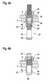
- FIGS. 4a and 4b show details of an example of such Blindnietbolzens 43 before and after deformation.
- Blind rivet bolts 43 of this or similar type are sold, inter alia, under the name "Huck BOM®". Details of such a blind rivet bolt are exemplary in FIG US 2,527,307 described.
- the blind rivet bolt 43 has a sleeve 45 and a pin 47 which extends, inter alia, through a hollow inner region of the sleeve 45.
- the pin 47 has a cross-sectionally enlarged head 48.
- An outer circumference of the head 48 corresponds approximately to an outer circumference of the sleeve 45 and is slightly smaller than an inner circumference of the connection openings 39 in the truss components 5 to be connected, so that the blind rivet bolt 43 easily and with a certain play in the form of a gap 49 in the connection openings 39 can be inserted.
- the sleeve 45 has a thickening 51 whose outer circumference is greater than the inner circumference of the connecting openings 39. The thickening 51 thus forms a stop, with which the blind rivet bolt 43 on insertion into the connecting openings 39 on an outer surface 53 of one of the truss components 5 is present.
- the sleeve 45 has near its distal end, which protrudes distally during assembly after insertion into the connection openings 39 on the truss components to be connected 5, a smaller material thickness than in a central region, which after insertion into the connection openings 39 in the interior the connection openings 39 is located.
- a material thickness of the sleeve 45 increases slightly proximal to a transition point 57. Accordingly, an inner diameter of the sleeve 45 decreases proximally of this transition point 57 slightly.
- the pin 47 in turn, has a shoulder portion 55, which still fits into the distal region of the sleeve 45 from its outer circumference, but is slightly larger than the inner circumference of the sleeve 45 proximal to the transition point 57.
- the pin 47 is displaced further towards the proximal end, thereby deforming the distal end of the sleeve 45 above the truss components 5 in order to form it in a form-fitting manner against a surface 54 of this connector component 5 (similar to a conventional blind rivet). in FIG. 4b not shown).
- connection openings 39 in the truss components 5 completely and backlash-free and thus, in addition to a positive connection in the longitudinal direction of the Blindnietbolzens 43, as he also In conventional rivets usually occurs, a positive connection in all directions transverse to this longitudinal direction is established, that is, a positive connection in directions in which the truss components 5 extend.
- the truss components 5 can be very stable and reliably connected to each other due to such acting in all directions of space form fit.
- the expansion of the sleeve 45 during the assembly process can serve to precisely align the two connecting openings 39 of the truss components 5 arranged adjacent to one another precisely, and thus to position the two truss components 5 very precisely relative to one another.
- a very precise positioning tolerance of, for example, a few tenths of a millimeter, in particular preferably less than 0.3 mm, can be achieved.
- FIG. 5 illustrates an alternate variant of a connector component 27 as may be used to connect the truss components 5 of the structure described herein.
- the connector component 27 has a hollow-cylindrical sleeve 59 and a first and a second cone 61 ', 61 "
- the sleeve 59 has a greater wall thickness in its axial center than at its axial edges
- the first cone 61 'and the second cone 61 are oppositely oriented and engage the sleeve 59, wherein conical outer surfaces 62 are preferably formed correspondingly complementary to the inner surfaces 58 of the sleeve 59
- the sleeve 59 may consist of a material which is easily plastically deformable, in particular metal such as steel, and may have a material thickness which allows a plastic deformation of the sleeve 59 by forces caused by the cone 61 ', 61 ".
- the tensioning element 64 can be used to displace the two cones 61 ', 61 "axially toward one another, that is to say towards the center of the sleeve 59.
- the outer surfaces 62 of the cones 61 ', 61 "slide along the inner surfaces 58 of the sleeve 59 and spread them radially outward, so that the sleeve 59 can also be referred to as an expansion sleeve and the cones 61', 61" as an expansion cone.
- 61 radially projecting flanges 67 are provided, which create in the assembled state against outer surfaces 53, 54 of the truss components 5 and can hold this in the longitudinal extension direction of the clamping element 64 form-fitting.
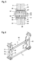
- FIG. 6 shows a preassembled so-called H-frame 69, which may form part of a truss 3 of a structure 1.
- the H-frame 69 has two vertically extending uprights 15 which are interconnected by two horizontally extending transverse struts 11.
- two connector components 27 provide a load-bearing mechanical connection between each of the uprights 15 and the crossbars 11. Due to their design positioning acting mounting can be further achieved by means of the connector components 27, that the uprights 15 and the cross braces 11 relative to each other extremely accurately positioned are connected.
- connection openings 39 in the individual uprights 15 and cross members 11 are formed with high precision in their distances from each other, for example, by computer-assisted laser cutter or water jet cutting, can be pre-assembled in this way, a high-precision manufactured H-frame 69, without necessarily any load-bearing welds are performed would.
- the connector components 27 may simply be mounted by, for example, unskilled workers.
- unskilled workers By preassembling a plurality of H-frame 69 and connecting these H-frame 69 inserted therebetween and also with connector components 27 positionally accurate mounted diagonal struts 13 and parts of the upper belt 7 and the lower belt 9 can therefore a total of a simple way and with little staff very quickly a total framework 3 for a structure 1 are assembled.
- Due to the precise positioning properties of the connector components 27 used in this case, a structure 1 assembled in this manner can be assembled with high precision over its entire length, with deviations from a desired geometry typically being less than a few millimeters, often even less than a few tenths of a millimeter ,
- frames 71 may be formed, by means of which, for example, rails of the passenger transport system can be attached to the supporting structure 1.
- the ribs 71 can be formed by a suitable geometric design of a sheet cut into shape for this purpose. Since the entire structure 1 can be manufactured with high precision, that is to say with at most very small deviations from a desired geometry, and also the frames 71 can be cut very precisely, rails to be fastened thereto can run very precisely in a desired geometry and do not need it be aligned during their assembly or subsequently, as is often the case with conventionally manufactured structures 1.
- the uprights 15 may be composed of two sub-components 31 in the form of suitably cut in sheet metal sheets.
- the two sub-components 31 may be provisionally connected to one another, for example, via a plug connection 32 in order to be able to handle the post 15 simply as a unit, for example during an assembly process.
- local welds can connect the two subcomponents 31 with one another.
- the connector 32 nor any welds here need to be carried load-bearing stable, but the sub-components 31 only temporarily fix during an assembly process together, provided that the two sub-components 31 later together with each other by connector components 27th be connected to each other load-bearing.
- plug connections and / or the welded connections between the subcomponents may also be designed to be load-bearing so far that the subcomponents 31 are reliably connected to one another so that they do not have to be connected to one another by connector components 27.
- further attachment areas may be provided for example Balustradenmaschine and / or trim components.
- rail blocks for the passenger transport system can be made of mated components and matched to the uprights 15 in the deflection.
- the angle brackets 25 at the transition points between the central region 17 and the upper or lower end region 19, 21 of the truss 3 essentially determine an angle of inclination of the finally installed escalator.
- the uprights 15 may have a flange with two mutually perpendicular surfaces, which may be connected in an assembled state with two surfaces of square tubes of the upper and lower chords 7, 9. Reinforcement angles can also be provided on the square tubes.
- end portions 19, 21 or entrance areas, or deflection heads of the passenger transport system may for example be cast from fiber reinforced cement.
- Such cast end portions 19, 21 may comprise roadways made of the cementitious material for the rollers of a step belt or pallet belt as well as receiving points of bearings and drive parts.
- the cement-molded end regions 19, 21 must also have connection points, so that a central region 17 constructed by means of connector components 27, top straps 7, bottom straps 9, uprights 15, cross struts 11 and diagonal struts 13 is inserted between the two cast end regions 19, 21 can.
- connection openings 39 suitably formed therein.
- a plurality of structurally identical uprights 15, cross struts 11 and / or diagonal struts 13 can be produced in series in advance and equipped with connection openings 39 tuned to bore-filling connector components.
- two sheet metal parts to be assembled together can be provisionally connected to each other in advance, for example, by being connected by means of plug connections which are secured locally inseparably by welds or crimp-like deformations.
- the uprights 15 have connecting openings 39 arranged at both ends, which can be arranged precisely with respect to one another and a parallel spacing of upper belt 7 and lower belt 9. At least one of the sheet metal parts of a stanchion 15 may have receptacles for fastening rails, wherein the receptacles 27 are formed precisely arranged relative to the connection openings 39 for the connector components 27.
- the connecting openings 39 to be formed in the transverse or diagonal struts 11, 13 are also arranged precisely spaced from each other at opposite ends of these struts.
- connection openings 39 must be precisely calculated with respect to an ultimately achieved individual truss geometry and formed in the upper and lower chords. In this case, a height of the uprights 15 and a distance of connection openings 39 in the diagonal struts 13 is to be considered.
- H-frames 69 To assemble the truss 3 of the structure 1, it may be advantageous to first preassemble a plurality of H-frames 69 by connecting each of two uprights 15 to at least one transverse strut 11 using the bore-filling connector components 27 described herein.
- Such H-frames 69 can easily be handled by a single person.
- the H-frames 69 can then be precisely connected by means of the connector components 27 with the upper straps 7 and the lower straps 9.
- the diagonal struts 13 can be inserted and in turn connected by means of connector components 27 with the already prefabricated remainder of the truss structure.
- At least one of the sheet-metal parts may hereby have receptacles for fastening rails and for their fastening by means of connector components 27 precisely aligned connecting openings 39.
- a particular advantage of the structure 1 described herein can be seen in the fact that it can be used by means of an assembly method using the special properties of this structure particularly simple for the assembly of passenger transport equipment in existing structures. For example, it may sometimes be necessary to replace existing passenger transport systems in a building or to retrofit a building in addition to passenger transport systems.
- Truss components 5 are introduced with the already pre-trained connection openings 39 to a mounting position within the building. If it is an exchange of a passenger transport system, the existing passenger transport system may be removed in advance if necessary. Furthermore, at least two support points for receiving the passenger transport system can be prepared in the building. If necessary, a temporary framework can also be created between such supports.
- the disassembled truss 3 can be assembled with its truss components 5 then directly within the building.
- the individual half-timbered components 5, which are in part provided as standard components of identical construction, can be connected to one another as described using the load-bearing and position-giving connector components 27 and thus form the high-precision truss 3.
- the truss 3 thus assembled can finally be mounted on the prepared mounting points of the structure within the building.
- the framework for the proposed structure 1 can be much more cost-effective to build than an example continuously welded framework.
- it can be assembled on site without mounting lays in an extremely short time, for example within a few hours or less days.
- the only tool in this case for example, a correspondingly suitable for the assembly of the connector components 39 rivet gun is required.
- a correspondingly suitable for the assembly of the connector components 39 rivet gun is required.
- For an assembly of the truss 3 advantageously no certified professionals such as certified welders are required.
- a subsequent straightening of the framework can usually be omitted.
- Components of the truss, in particular its truss components 5, can be painted or, in particular, galvanized prior to their assembly.
- a transport volume of the initially dismantled truss 3 can be extremely small.
- the individual truss components 5, for example, can be easily introduced through existing openings in an interior of a building be without, for example, walls of the building would have to be broken. Even dirt and noise emissions at the installation site can be minimized by the use of clean and precise connection technology using the special connector components 27, for example, cleaning, cutting and grinding and welding work on, for example empty salvaged trusses, as otherwise often incurred in modernization solutions, not necessary are. Furthermore, it can be seen as an advantage that, due to the possibility of being able to build the truss 3 at the installation location, a high local production proportion can be achieved. This can be a crucial selling factor, especially for public sector contracts.
Landscapes
- Escalators And Moving Walkways (AREA)
Priority Applications (1)
| Application Number | Priority Date | Filing Date | Title |
|---|---|---|---|
| EP15187455.9A EP3150539A1 (fr) | 2015-09-29 | 2015-09-29 | Ossature porteuse pour une installation de transport de personnes |
Applications Claiming Priority (1)
| Application Number | Priority Date | Filing Date | Title |
|---|---|---|---|
| EP15187455.9A EP3150539A1 (fr) | 2015-09-29 | 2015-09-29 | Ossature porteuse pour une installation de transport de personnes |
Publications (1)
| Publication Number | Publication Date |
|---|---|
| EP3150539A1 true EP3150539A1 (fr) | 2017-04-05 |
Family
ID=54249372
Family Applications (1)
| Application Number | Title | Priority Date | Filing Date |
|---|---|---|---|
| EP15187455.9A Withdrawn EP3150539A1 (fr) | 2015-09-29 | 2015-09-29 | Ossature porteuse pour une installation de transport de personnes |
Country Status (1)
| Country | Link |
|---|---|
| EP (1) | EP3150539A1 (fr) |
Cited By (2)
| Publication number | Priority date | Publication date | Assignee | Title |
|---|---|---|---|---|
| CN107857186A (zh) * | 2017-11-24 | 2018-03-30 | 江南嘉捷电梯股份有限公司 | 一种桁架支架 |
| WO2020173753A3 (fr) * | 2019-02-27 | 2020-12-17 | Inventio Ag | Zone de liaison de section de charpente |
Citations (5)
| Publication number | Priority date | Publication date | Assignee | Title |
|---|---|---|---|---|
| US2527307A (en) | 1947-06-23 | 1950-10-24 | Huck Mfg Co | Rivet and method of riveting |
| US4958473A (en) * | 1988-06-06 | 1990-09-25 | Hitachi, Ltd. | Frame, angle member for use in the frame and method of making joint portion of the angel member |
| WO2011073708A1 (fr) | 2009-12-15 | 2011-06-23 | Otis Elevator Company | Construction en treillis pour un convoyeur de passagers |
| CN201942404U (zh) * | 2010-12-28 | 2011-08-24 | 鸿运汽车有限公司 | 铆接结构扶梯桁架 |
| WO2013029979A1 (fr) | 2011-08-30 | 2013-03-07 | Inventio Ag | Escalier mécanique ou tapis roulant comprenant une tôle inférieure |
-
2015
- 2015-09-29 EP EP15187455.9A patent/EP3150539A1/fr not_active Withdrawn
Patent Citations (5)
| Publication number | Priority date | Publication date | Assignee | Title |
|---|---|---|---|---|
| US2527307A (en) | 1947-06-23 | 1950-10-24 | Huck Mfg Co | Rivet and method of riveting |
| US4958473A (en) * | 1988-06-06 | 1990-09-25 | Hitachi, Ltd. | Frame, angle member for use in the frame and method of making joint portion of the angel member |
| WO2011073708A1 (fr) | 2009-12-15 | 2011-06-23 | Otis Elevator Company | Construction en treillis pour un convoyeur de passagers |
| CN201942404U (zh) * | 2010-12-28 | 2011-08-24 | 鸿运汽车有限公司 | 铆接结构扶梯桁架 |
| WO2013029979A1 (fr) | 2011-08-30 | 2013-03-07 | Inventio Ag | Escalier mécanique ou tapis roulant comprenant une tôle inférieure |
Non-Patent Citations (2)
| Title |
|---|
| "Hollo-Bolt - The Original Expansion Bolt for Structural Steel", 15 June 2012 (2012-06-15), XP055261728, Retrieved from the Internet <URL:http://www.ancon.com.au/downloads/s3/l1/hollo-bolt.pdf> [retrieved on 20160331] * |
| "Huck BOM - The highest strength blind fasteners in the world.", 15 April 2015 (2015-04-15), XP055261721, Retrieved from the Internet <URL:https://www.alcoa.com/fastening_systems_and_rings/commercial/catalog/pdf/huck/en/AF201_Bom_Brochure.pdf> [retrieved on 20160331] * |
Cited By (4)
| Publication number | Priority date | Publication date | Assignee | Title |
|---|---|---|---|---|
| CN107857186A (zh) * | 2017-11-24 | 2018-03-30 | 江南嘉捷电梯股份有限公司 | 一种桁架支架 |
| CN107857186B (zh) * | 2017-11-24 | 2023-06-13 | 苏州江南嘉捷电梯有限公司 | 一种桁架支架 |
| WO2020173753A3 (fr) * | 2019-02-27 | 2020-12-17 | Inventio Ag | Zone de liaison de section de charpente |
| US11913215B2 (en) | 2019-02-27 | 2024-02-27 | Inventio Ag | Truss section connection region |
Similar Documents
| Publication | Publication Date | Title |
|---|---|---|
| EP3356277B1 (fr) | Procédé de montage d'une ossature porteuse pour une installation de transport de personnes dans un bâtiment | |
| EP2527565B1 (fr) | Montant | |
| EP2900585B1 (fr) | Système de voie pour un escalier roulant ou un trottoir roulant | |
| EP2882634B1 (fr) | Structure de convoyeur aerien au-dessus d'un portique | |
| EP3230539B1 (fr) | Procédé pour ériger une construction de tour tubulaire et tour tubulaire | |
| EP3150540A1 (fr) | Procede de fabrication d'une ossature porteuse pour une installation de transport de personnes | |
| EP3016843B1 (fr) | Convoyeur aérien équipé de modules de châssis porteur | |
| EP3137406B1 (fr) | Système de voie pour un escalier roulant ou un trottoir roulant | |
| EP4063588B1 (fr) | Composant de liaison | |
| DE102015115645A1 (de) | Verfahren zur Herstellung und zum Errichten eines Rohrturmbauwerks | |
| EP3150539A1 (fr) | Ossature porteuse pour une installation de transport de personnes | |
| EP3931142B1 (fr) | Zone de raccordement de la section de treillis | |
| EP3049316B1 (fr) | Système de convoyeur aérien à monter au plafond d'une ligne de montage | |
| WO1997014596A1 (fr) | Element modulaire et procede de fabrication | |
| DE19619617C1 (de) | Verbindung zwischen zwei Bauteilen und modulares Bauteil | |
| DE19538793C2 (de) | Modulelement | |
| DE102010008668A1 (de) | Verbindungssystem und Verfahren zum Herstellen eines Verbindungssystems | |
| DE10341350B4 (de) | Verbindung einer Seitenwand mit einem Untergestell, insbesondere eines Schienenenfahrzeuges | |
| WO2024078839A1 (fr) | Système de guidage modulaire doté d'une liaison de module d'ajustement de forme/ de force, procédé et utilisation | |
| WO2024078878A1 (fr) | Système de guidage comprenant au moins trois sections longitudinales, procédé et utilisation | |
| WO2022117635A1 (fr) | Dispositif d'agencement pour composants principaux d'un escalier roulant ou d'un trottoir roulant | |
| EP4353664A1 (fr) | Dispositif de voie de circulation comportant au moins trois sections longitudinales, procédé et utilisation | |
| EP4353654A1 (fr) | Dispositif de voie de circulation comportant au moins trois sections longitudinales, procédé et utilisation | |
| WO2024078840A1 (fr) | Procédé d'assemblage d'un système de voie de guidage modulaire, système et utilisation | |
| WO2024078841A1 (fr) | Ensemble raccordement de module de section longitudinale et procédé d'assemblage d'appareil à chenille |
Legal Events
| Date | Code | Title | Description |
|---|---|---|---|
| PUAI | Public reference made under article 153(3) epc to a published international application that has entered the european phase |
Free format text: ORIGINAL CODE: 0009012 |
|
| AK | Designated contracting states |
Kind code of ref document: A1 Designated state(s): AL AT BE BG CH CY CZ DE DK EE ES FI FR GB GR HR HU IE IS IT LI LT LU LV MC MK MT NL NO PL PT RO RS SE SI SK SM TR |
|
| AX | Request for extension of the european patent |
Extension state: BA ME |
|
| STAA | Information on the status of an ep patent application or granted ep patent |
Free format text: STATUS: THE APPLICATION IS DEEMED TO BE WITHDRAWN |
|
| 18D | Application deemed to be withdrawn |
Effective date: 20171006 |