EP3004918B1 - Interferenzunterdrückung bei einem fmcw-radar - Google Patents
Interferenzunterdrückung bei einem fmcw-radar Download PDFInfo
- Publication number
- EP3004918B1 EP3004918B1 EP14715624.4A EP14715624A EP3004918B1 EP 3004918 B1 EP3004918 B1 EP 3004918B1 EP 14715624 A EP14715624 A EP 14715624A EP 3004918 B1 EP3004918 B1 EP 3004918B1
- Authority
- EP
- European Patent Office
- Prior art keywords
- codeset
- radar
- phase
- partial transmission
- code
- Prior art date
- Legal status (The legal status is an assumption and is not a legal conclusion. Google has not performed a legal analysis and makes no representation as to the accuracy of the status listed.)
- Active
Links
Images


Classifications
-
- G—PHYSICS
- G01—MEASURING; TESTING
- G01S—RADIO DIRECTION-FINDING; RADIO NAVIGATION; DETERMINING DISTANCE OR VELOCITY BY USE OF RADIO WAVES; LOCATING OR PRESENCE-DETECTING BY USE OF THE REFLECTION OR RERADIATION OF RADIO WAVES; ANALOGOUS ARRANGEMENTS USING OTHER WAVES
- G01S7/00—Details of systems according to groups G01S13/00, G01S15/00, G01S17/00
- G01S7/02—Details of systems according to groups G01S13/00, G01S15/00, G01S17/00 of systems according to group G01S13/00
- G01S7/023—Interference mitigation, e.g. reducing or avoiding non-intentional interference with other HF-transmitters, base station transmitters for mobile communication or other radar systems, e.g. using electro-magnetic interference [EMI] reduction techniques
-
- G—PHYSICS
- G01—MEASURING; TESTING
- G01S—RADIO DIRECTION-FINDING; RADIO NAVIGATION; DETERMINING DISTANCE OR VELOCITY BY USE OF RADIO WAVES; LOCATING OR PRESENCE-DETECTING BY USE OF THE REFLECTION OR RERADIATION OF RADIO WAVES; ANALOGOUS ARRANGEMENTS USING OTHER WAVES
- G01S13/00—Systems using the reflection or reradiation of radio waves, e.g. radar systems; Analogous systems using reflection or reradiation of waves whose nature or wavelength is irrelevant or unspecified
- G01S13/02—Systems using reflection of radio waves, e.g. primary radar systems; Analogous systems
- G01S13/06—Systems determining position data of a target
- G01S13/08—Systems for measuring distance only
- G01S13/32—Systems for measuring distance only using transmission of continuous waves, whether amplitude-, frequency-, or phase-modulated, or unmodulated
- G01S13/325—Systems for measuring distance only using transmission of continuous waves, whether amplitude-, frequency-, or phase-modulated, or unmodulated using transmission of coded signals, e.g. P.S.K. signals
-
- G—PHYSICS
- G01—MEASURING; TESTING
- G01S—RADIO DIRECTION-FINDING; RADIO NAVIGATION; DETERMINING DISTANCE OR VELOCITY BY USE OF RADIO WAVES; LOCATING OR PRESENCE-DETECTING BY USE OF THE REFLECTION OR RERADIATION OF RADIO WAVES; ANALOGOUS ARRANGEMENTS USING OTHER WAVES
- G01S13/00—Systems using the reflection or reradiation of radio waves, e.g. radar systems; Analogous systems using reflection or reradiation of waves whose nature or wavelength is irrelevant or unspecified
- G01S13/02—Systems using reflection of radio waves, e.g. primary radar systems; Analogous systems
- G01S13/06—Systems determining position data of a target
- G01S13/08—Systems for measuring distance only
- G01S13/32—Systems for measuring distance only using transmission of continuous waves, whether amplitude-, frequency-, or phase-modulated, or unmodulated
- G01S13/34—Systems for measuring distance only using transmission of continuous waves, whether amplitude-, frequency-, or phase-modulated, or unmodulated using transmission of continuous, frequency-modulated waves while heterodyning the received signal, or a signal derived therefrom, with a locally-generated signal related to the contemporaneously transmitted signal
- G01S13/343—Systems for measuring distance only using transmission of continuous waves, whether amplitude-, frequency-, or phase-modulated, or unmodulated using transmission of continuous, frequency-modulated waves while heterodyning the received signal, or a signal derived therefrom, with a locally-generated signal related to the contemporaneously transmitted signal using sawtooth modulation
-
- G—PHYSICS
- G01—MEASURING; TESTING
- G01S—RADIO DIRECTION-FINDING; RADIO NAVIGATION; DETERMINING DISTANCE OR VELOCITY BY USE OF RADIO WAVES; LOCATING OR PRESENCE-DETECTING BY USE OF THE REFLECTION OR RERADIATION OF RADIO WAVES; ANALOGOUS ARRANGEMENTS USING OTHER WAVES
- G01S13/00—Systems using the reflection or reradiation of radio waves, e.g. radar systems; Analogous systems using reflection or reradiation of waves whose nature or wavelength is irrelevant or unspecified
- G01S13/02—Systems using reflection of radio waves, e.g. primary radar systems; Analogous systems
- G01S13/06—Systems determining position data of a target
- G01S13/08—Systems for measuring distance only
- G01S13/32—Systems for measuring distance only using transmission of continuous waves, whether amplitude-, frequency-, or phase-modulated, or unmodulated
- G01S13/34—Systems for measuring distance only using transmission of continuous waves, whether amplitude-, frequency-, or phase-modulated, or unmodulated using transmission of continuous, frequency-modulated waves while heterodyning the received signal, or a signal derived therefrom, with a locally-generated signal related to the contemporaneously transmitted signal
- G01S13/345—Systems for measuring distance only using transmission of continuous waves, whether amplitude-, frequency-, or phase-modulated, or unmodulated using transmission of continuous, frequency-modulated waves while heterodyning the received signal, or a signal derived therefrom, with a locally-generated signal related to the contemporaneously transmitted signal using triangular modulation
-
- G—PHYSICS
- G01—MEASURING; TESTING
- G01S—RADIO DIRECTION-FINDING; RADIO NAVIGATION; DETERMINING DISTANCE OR VELOCITY BY USE OF RADIO WAVES; LOCATING OR PRESENCE-DETECTING BY USE OF THE REFLECTION OR RERADIATION OF RADIO WAVES; ANALOGOUS ARRANGEMENTS USING OTHER WAVES
- G01S13/00—Systems using the reflection or reradiation of radio waves, e.g. radar systems; Analogous systems using reflection or reradiation of waves whose nature or wavelength is irrelevant or unspecified
- G01S13/02—Systems using reflection of radio waves, e.g. primary radar systems; Analogous systems
- G01S13/06—Systems determining position data of a target
- G01S13/08—Systems for measuring distance only
- G01S13/32—Systems for measuring distance only using transmission of continuous waves, whether amplitude-, frequency-, or phase-modulated, or unmodulated
- G01S13/36—Systems for measuring distance only using transmission of continuous waves, whether amplitude-, frequency-, or phase-modulated, or unmodulated with phase comparison between the received signal and the contemporaneously transmitted signal
- G01S13/38—Systems for measuring distance only using transmission of continuous waves, whether amplitude-, frequency-, or phase-modulated, or unmodulated with phase comparison between the received signal and the contemporaneously transmitted signal wherein more than one modulation frequency is used
-
- G—PHYSICS
- G01—MEASURING; TESTING
- G01S—RADIO DIRECTION-FINDING; RADIO NAVIGATION; DETERMINING DISTANCE OR VELOCITY BY USE OF RADIO WAVES; LOCATING OR PRESENCE-DETECTING BY USE OF THE REFLECTION OR RERADIATION OF RADIO WAVES; ANALOGOUS ARRANGEMENTS USING OTHER WAVES
- G01S13/00—Systems using the reflection or reradiation of radio waves, e.g. radar systems; Analogous systems using reflection or reradiation of waves whose nature or wavelength is irrelevant or unspecified
- G01S13/02—Systems using reflection of radio waves, e.g. primary radar systems; Analogous systems
- G01S13/50—Systems of measurement based on relative movement of target
- G01S13/52—Discriminating between fixed and moving objects or between objects moving at different speeds
- G01S13/536—Discriminating between fixed and moving objects or between objects moving at different speeds using transmission of continuous unmodulated waves, amplitude-, frequency-, or phase-modulated waves
-
- G—PHYSICS
- G01—MEASURING; TESTING
- G01S—RADIO DIRECTION-FINDING; RADIO NAVIGATION; DETERMINING DISTANCE OR VELOCITY BY USE OF RADIO WAVES; LOCATING OR PRESENCE-DETECTING BY USE OF THE REFLECTION OR RERADIATION OF RADIO WAVES; ANALOGOUS ARRANGEMENTS USING OTHER WAVES
- G01S13/00—Systems using the reflection or reradiation of radio waves, e.g. radar systems; Analogous systems using reflection or reradiation of waves whose nature or wavelength is irrelevant or unspecified
- G01S13/02—Systems using reflection of radio waves, e.g. primary radar systems; Analogous systems
- G01S13/50—Systems of measurement based on relative movement of target
- G01S13/58—Velocity or trajectory determination systems; Sense-of-movement determination systems
- G01S13/583—Velocity or trajectory determination systems; Sense-of-movement determination systems using transmission of continuous unmodulated waves, amplitude-, frequency-, or phase-modulated waves and based upon the Doppler effect resulting from movement of targets
- G01S13/584—Velocity or trajectory determination systems; Sense-of-movement determination systems using transmission of continuous unmodulated waves, amplitude-, frequency-, or phase-modulated waves and based upon the Doppler effect resulting from movement of targets adapted for simultaneous range and velocity measurements
-
- G—PHYSICS
- G01—MEASURING; TESTING
- G01S—RADIO DIRECTION-FINDING; RADIO NAVIGATION; DETERMINING DISTANCE OR VELOCITY BY USE OF RADIO WAVES; LOCATING OR PRESENCE-DETECTING BY USE OF THE REFLECTION OR RERADIATION OF RADIO WAVES; ANALOGOUS ARRANGEMENTS USING OTHER WAVES
- G01S13/00—Systems using the reflection or reradiation of radio waves, e.g. radar systems; Analogous systems using reflection or reradiation of waves whose nature or wavelength is irrelevant or unspecified
- G01S13/87—Combinations of radar systems, e.g. primary radar and secondary radar
- G01S13/878—Combination of several spaced transmitters or receivers of known location for determining the position of a transponder or a reflector
-
- G—PHYSICS
- G01—MEASURING; TESTING
- G01S—RADIO DIRECTION-FINDING; RADIO NAVIGATION; DETERMINING DISTANCE OR VELOCITY BY USE OF RADIO WAVES; LOCATING OR PRESENCE-DETECTING BY USE OF THE REFLECTION OR RERADIATION OF RADIO WAVES; ANALOGOUS ARRANGEMENTS USING OTHER WAVES
- G01S13/00—Systems using the reflection or reradiation of radio waves, e.g. radar systems; Analogous systems using reflection or reradiation of waves whose nature or wavelength is irrelevant or unspecified
- G01S13/88—Radar or analogous systems specially adapted for specific applications
- G01S13/93—Radar or analogous systems specially adapted for specific applications for anti-collision purposes
- G01S13/931—Radar or analogous systems specially adapted for specific applications for anti-collision purposes of land vehicles
-
- G—PHYSICS
- G01—MEASURING; TESTING
- G01S—RADIO DIRECTION-FINDING; RADIO NAVIGATION; DETERMINING DISTANCE OR VELOCITY BY USE OF RADIO WAVES; LOCATING OR PRESENCE-DETECTING BY USE OF THE REFLECTION OR RERADIATION OF RADIO WAVES; ANALOGOUS ARRANGEMENTS USING OTHER WAVES
- G01S7/00—Details of systems according to groups G01S13/00, G01S15/00, G01S17/00
- G01S7/02—Details of systems according to groups G01S13/00, G01S15/00, G01S17/00 of systems according to group G01S13/00
- G01S7/023—Interference mitigation, e.g. reducing or avoiding non-intentional interference with other HF-transmitters, base station transmitters for mobile communication or other radar systems, e.g. using electro-magnetic interference [EMI] reduction techniques
- G01S7/0232—Avoidance by frequency multiplex
-
- G—PHYSICS
- G01—MEASURING; TESTING
- G01S—RADIO DIRECTION-FINDING; RADIO NAVIGATION; DETERMINING DISTANCE OR VELOCITY BY USE OF RADIO WAVES; LOCATING OR PRESENCE-DETECTING BY USE OF THE REFLECTION OR RERADIATION OF RADIO WAVES; ANALOGOUS ARRANGEMENTS USING OTHER WAVES
- G01S7/00—Details of systems according to groups G01S13/00, G01S15/00, G01S17/00
- G01S7/02—Details of systems according to groups G01S13/00, G01S15/00, G01S17/00 of systems according to group G01S13/00
- G01S7/023—Interference mitigation, e.g. reducing or avoiding non-intentional interference with other HF-transmitters, base station transmitters for mobile communication or other radar systems, e.g. using electro-magnetic interference [EMI] reduction techniques
- G01S7/0233—Avoidance by phase multiplex
-
- G—PHYSICS
- G01—MEASURING; TESTING
- G01S—RADIO DIRECTION-FINDING; RADIO NAVIGATION; DETERMINING DISTANCE OR VELOCITY BY USE OF RADIO WAVES; LOCATING OR PRESENCE-DETECTING BY USE OF THE REFLECTION OR RERADIATION OF RADIO WAVES; ANALOGOUS ARRANGEMENTS USING OTHER WAVES
- G01S7/00—Details of systems according to groups G01S13/00, G01S15/00, G01S17/00
- G01S7/02—Details of systems according to groups G01S13/00, G01S15/00, G01S17/00 of systems according to group G01S13/00
- G01S7/023—Interference mitigation, e.g. reducing or avoiding non-intentional interference with other HF-transmitters, base station transmitters for mobile communication or other radar systems, e.g. using electro-magnetic interference [EMI] reduction techniques
- G01S7/0234—Avoidance by code multiplex
-
- G—PHYSICS
- G01—MEASURING; TESTING
- G01S—RADIO DIRECTION-FINDING; RADIO NAVIGATION; DETERMINING DISTANCE OR VELOCITY BY USE OF RADIO WAVES; LOCATING OR PRESENCE-DETECTING BY USE OF THE REFLECTION OR RERADIATION OF RADIO WAVES; ANALOGOUS ARRANGEMENTS USING OTHER WAVES
- G01S13/00—Systems using the reflection or reradiation of radio waves, e.g. radar systems; Analogous systems using reflection or reradiation of waves whose nature or wavelength is irrelevant or unspecified
- G01S13/02—Systems using reflection of radio waves, e.g. primary radar systems; Analogous systems
- G01S13/06—Systems determining position data of a target
- G01S13/08—Systems for measuring distance only
- G01S13/10—Systems for measuring distance only using transmission of interrupted, pulse modulated waves
- G01S13/26—Systems for measuring distance only using transmission of interrupted, pulse modulated waves wherein the transmitted pulses use a frequency- or phase-modulated carrier wave
- G01S13/28—Systems for measuring distance only using transmission of interrupted, pulse modulated waves wherein the transmitted pulses use a frequency- or phase-modulated carrier wave with time compression of received pulses
- G01S13/282—Systems for measuring distance only using transmission of interrupted, pulse modulated waves wherein the transmitted pulses use a frequency- or phase-modulated carrier wave with time compression of received pulses using a frequency modulated carrier wave
-
- G—PHYSICS
- G01—MEASURING; TESTING
- G01S—RADIO DIRECTION-FINDING; RADIO NAVIGATION; DETERMINING DISTANCE OR VELOCITY BY USE OF RADIO WAVES; LOCATING OR PRESENCE-DETECTING BY USE OF THE REFLECTION OR RERADIATION OF RADIO WAVES; ANALOGOUS ARRANGEMENTS USING OTHER WAVES
- G01S13/00—Systems using the reflection or reradiation of radio waves, e.g. radar systems; Analogous systems using reflection or reradiation of waves whose nature or wavelength is irrelevant or unspecified
- G01S13/02—Systems using reflection of radio waves, e.g. primary radar systems; Analogous systems
- G01S13/06—Systems determining position data of a target
- G01S13/08—Systems for measuring distance only
- G01S13/10—Systems for measuring distance only using transmission of interrupted, pulse modulated waves
- G01S13/26—Systems for measuring distance only using transmission of interrupted, pulse modulated waves wherein the transmitted pulses use a frequency- or phase-modulated carrier wave
- G01S13/28—Systems for measuring distance only using transmission of interrupted, pulse modulated waves wherein the transmitted pulses use a frequency- or phase-modulated carrier wave with time compression of received pulses
- G01S13/284—Systems for measuring distance only using transmission of interrupted, pulse modulated waves wherein the transmitted pulses use a frequency- or phase-modulated carrier wave with time compression of received pulses using coded pulses
- G01S13/286—Systems for measuring distance only using transmission of interrupted, pulse modulated waves wherein the transmitted pulses use a frequency- or phase-modulated carrier wave with time compression of received pulses using coded pulses frequency shift keyed
-
- G—PHYSICS
- G01—MEASURING; TESTING
- G01S—RADIO DIRECTION-FINDING; RADIO NAVIGATION; DETERMINING DISTANCE OR VELOCITY BY USE OF RADIO WAVES; LOCATING OR PRESENCE-DETECTING BY USE OF THE REFLECTION OR RERADIATION OF RADIO WAVES; ANALOGOUS ARRANGEMENTS USING OTHER WAVES
- G01S13/00—Systems using the reflection or reradiation of radio waves, e.g. radar systems; Analogous systems using reflection or reradiation of waves whose nature or wavelength is irrelevant or unspecified
- G01S13/02—Systems using reflection of radio waves, e.g. primary radar systems; Analogous systems
- G01S13/06—Systems determining position data of a target
- G01S13/08—Systems for measuring distance only
- G01S13/10—Systems for measuring distance only using transmission of interrupted, pulse modulated waves
- G01S13/26—Systems for measuring distance only using transmission of interrupted, pulse modulated waves wherein the transmitted pulses use a frequency- or phase-modulated carrier wave
- G01S13/28—Systems for measuring distance only using transmission of interrupted, pulse modulated waves wherein the transmitted pulses use a frequency- or phase-modulated carrier wave with time compression of received pulses
- G01S13/284—Systems for measuring distance only using transmission of interrupted, pulse modulated waves wherein the transmitted pulses use a frequency- or phase-modulated carrier wave with time compression of received pulses using coded pulses
- G01S13/288—Systems for measuring distance only using transmission of interrupted, pulse modulated waves wherein the transmitted pulses use a frequency- or phase-modulated carrier wave with time compression of received pulses using coded pulses phase modulated
-
- G—PHYSICS
- G01—MEASURING; TESTING
- G01S—RADIO DIRECTION-FINDING; RADIO NAVIGATION; DETERMINING DISTANCE OR VELOCITY BY USE OF RADIO WAVES; LOCATING OR PRESENCE-DETECTING BY USE OF THE REFLECTION OR RERADIATION OF RADIO WAVES; ANALOGOUS ARRANGEMENTS USING OTHER WAVES
- G01S13/00—Systems using the reflection or reradiation of radio waves, e.g. radar systems; Analogous systems using reflection or reradiation of waves whose nature or wavelength is irrelevant or unspecified
- G01S13/88—Radar or analogous systems specially adapted for specific applications
- G01S13/93—Radar or analogous systems specially adapted for specific applications for anti-collision purposes
- G01S13/931—Radar or analogous systems specially adapted for specific applications for anti-collision purposes of land vehicles
- G01S2013/9327—Sensor installation details
- G01S2013/93271—Sensor installation details in the front of the vehicles
-
- G—PHYSICS
- G01—MEASURING; TESTING
- G01S—RADIO DIRECTION-FINDING; RADIO NAVIGATION; DETERMINING DISTANCE OR VELOCITY BY USE OF RADIO WAVES; LOCATING OR PRESENCE-DETECTING BY USE OF THE REFLECTION OR RERADIATION OF RADIO WAVES; ANALOGOUS ARRANGEMENTS USING OTHER WAVES
- G01S7/00—Details of systems according to groups G01S13/00, G01S15/00, G01S17/00
- G01S7/02—Details of systems according to groups G01S13/00, G01S15/00, G01S17/00 of systems according to group G01S13/00
- G01S7/35—Details of non-pulse systems
- G01S7/352—Receivers
- G01S7/356—Receivers involving particularities of FFT processing
Definitions
- the invention relates to the determination of distances and / or relative speeds of objects with an FMCW radar.
- the invention relates to an FMCW radar sensor, an FMCW radar system with a first and at least one second radar sensor, and a radar system for a vehicle fleet comprising a plurality of FMCW radar sensors.
- Radar sensors are used in motor vehicles, for example, to measure the distances, relative speeds and azimuth angles of vehicles or other objects located in the apron of their own vehicle.
- the transmission frequency of a continuous radar signal is modulated in a ramp-like manner.
- a baseband signal is generated from a received signal by mixing with the transmitted signal and is then evaluated.
- FMCW radar sensors which operate according to the chirp sequence modulation method, in which the transmitted signal comprises at least one sequence of similar frequency modulation ramps (chirps).
- the modulation parameters such as the ramp duration and the frequency swing as well as the time interval between adjacent ramps of a sequence are the same within a sequence.
- the radar objects are initially separated according to their distances by performing a first Fourier transformation of the baseband signal for the individual frequency ramps of the transmission signal.
- the spectra of the first Fourier transformations of the frequency ramps of a sequence are then used as an input signal for a second Fourier transformation.
- the radar objects are separated according to their speeds on the basis of changes in the phase positions via the sequence of the radar echoes of the individual frequency ramps.
- WO 2005/111655 A2 describes a system for the simultaneous operation of several radar systems on a common carrier frequency and in the same geographical area.
- complementary codes for radar pulses can be used so that each radar system works with a unique code to significantly reduce the risk of crosstalk between the radar systems.
- a radar pulse with four sinusoidal components with phase shifts is used according to a row of a Frank code 4x4 matrix, the rows of which are orthogonal to one another.
- the received signals are processed and summed with a corresponding "matched" filter.
- Another example of complementary codes are Hadamard codes.
- a "mismatched" filter is used.
- a pulse radar in which a transmission signal is modulated according to a pseudo-noise code by amplitude modulation, phase modulation or frequency modulation. Modulation with a delayed code takes place in a reception branch. The distance from a target object is inferred on the basis of the time delay from transmission to reception of the radar pulses.
- orthogonal codes are used, which are generated from the pseudo-noise code, for example by counters and EXOR gates.
- WO 2010/115418 A2 is known a radar system with two transmitting antennas arranged in a plane and at a defined lateral distance and a common receiving antenna, in which both transmitting antennas are operated simultaneously according to a sequence of similar frequency ramps, with a switchable inverter changing the phase of the signal of the first transmitting antenna from ramp to ramp randomly varied by 0 ° or 180 °.
- a first discrete Fourier transformation (DFT) over the samples of each frequency ramp
- a second DFT over the ramp sequence is calculated once with a phase correction and once without a phase correction in order to obtain separate spectra for reception signals originating from the respective transmitting antennas in order to obtain azimuth information.
- DFT discrete Fourier transformation
- WO 2010/000252 A2 describes a similar radar system in which the phase of a transmission signal is determined at random.
- the object of the invention is to provide an FMCW radar system and an FMCW radar sensor with chirp sequence modulation, in which unwanted signals from other radar sensors can be effectively suppressed.
- Another approach is the detection of interference in the time signal of the radar sensor based on interpolation of the time signal.
- the model assumption is assumed that only a small area of the time signal is disturbed. If short ramp times are used or if several interfering signals occur at the same time, however, interference detection and interpolation are no longer possible.
- a radar system according to claim 1 and a radar sensor according to claim 6.
- Further embodiments of the invention are defined by the dependent claims. Embodiments that are described here and are not covered by the claims serve to facilitate understanding of the invention.
- a Fourier analysis is carried out in the form of a two-dimensional, two-stage discrete Fourier transformation.
- a first Fourier transformation maps a coherent oscillation, corresponding to a distance-dependent signal component, within the radar echo of a frequency ramp by a peak in the one-dimensional spectrum.
- a second Fourier transformation is carried out via the one-dimensional spectra of the first Fourier transformation, which phase-demodulated here, however, and reproduces a coherent vibration corresponding to a Doppler component via the radar echoes of the sequence of frequency ramps due to the position of the peak in the spectrum of the second Fourier transformation.
- the result of the two-dimensional Fourier transformation is a two-dimensional, discrete or rasterized one, ie in distance / speed cells divided, spectrum.
- the phase demodulation preferably takes place in that the one-dimensional spectra of the frequency ramps are multiplied by the respective conjugate complex element of the code sequence used in the receiver.
- the second Fourier transformation already includes the summation of the respective terms and therefore supplies the value of the autocorrelation or cross-correlation as a factor of the amplitude in the corresponding distance / speed cell of the two-dimensional spectrum.
- the phase demodulation according to the invention results in a power peak of a radar echo after the second Fourier transformation only if there is a coherent oscillation of the phase position of the radar echoes via the sequence of frequency ramps after the phase demodulation.
- This condition is met by radar echoes whose transmission signal has been phase-modulated with the code sequence, which correlates with the code sequence used for phase demodulation.
- the baseband signal of a radar echo contains a portion of the at least one second radar sensor, the corresponding peaks obtained after the first Fourier transformation after phase demodulation have no coherence over the sequence of the frequency ramps.
- the cross correlation of the code sequences provides the factor zero here.
- the object is further achieved by a radar system according to claim 6.
- the separate processing of the radar echoes of the partial transmission signals up to the determination of a two-dimensional spectrum corresponds, for example, to the evaluation steps described above.
- phase demodulation and summation of the two-dimensional spectra for the partial signals only result in a power peak of a radar echo in the summed spectrum if the separated spectra add up to a spectrum in which a coherent oscillation of the summed phase positions of the radar echoes over the consequences of the frequency ramps is available.
- the sum of the autocorrelation functions with zero time shift is obtained as a factor of the amplitude in the corresponding distance / speed cell.
- the sum of the cross-correlation functions is obtained as a factor of the amplitude. According to the code set orthogonality relationship, this is zero, regardless of the value of a time shift between the code sequences.
- code sets with code sequences which fulfill the code set-orthogonality relationship means that mutual interference can be suppressed even when phase modulation of two transmission signals is not synchronized in time. External interference between radar sensors of two vehicles can thus be suppressed.
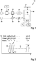
- the in Fig. 1 FMCW radar sensor 10 shown is installed in the front of a motor vehicle. It comprises an oscillator 12 for generating a transmission signal, a frequency modulation device 14 for controlling the frequency of the oscillator 12 and a control and evaluation unit 16 which can be connected to a vehicle bus system 17. An output of the oscillator 12 is connected to a transmit antenna element 20 via a controllable phase modulator 18. Furthermore, an output of the oscillator 12 is connected to a mixer 22. This is configured to mix a received signal received by a receiving antenna element 24 with the frequency-modulated signal of the oscillator 12 in order to generate a baseband signal s. The baseband signal is sampled and digitized by an analog-to-digital converter 26. Mixing and digitizing takes place while maintaining the phase relationships between the received signal and the transmitted signal.
- the control and evaluation unit 16 controls the frequency modulation device 14 and comprises a signal processing unit 28 for evaluating the sample values of the baseband signal s.
- Fig. 2 shows an example of a modulation scheme of the transmission signal output by the oscillator 12 and phase-modulated by the phase modulator 18.
- the frequency f of the transmission signal is plotted as a function of time t.
- the frequency modulation device 14 is set up to modulate the signal of the oscillator 12 in accordance with a chirp sequence modulation with at least one sequence of frequency ramps 30 which follow one another at regular time intervals, in particular a sequence of linear ramps of the same slope, the same center frequency and the same strokes .
- the frequency modulation ramps are also referred to as chirps, frequency ramps or simply as ramps.
- the phase modulator 18 is set up to modulate the phases of the chirps according to a code sequence C m , hereinafter also referred to as code C m .
- code C m a code sequence
- the number of ramps in the sequence is L and is equal to the length of the code C m .
- the chirp sequence modulation and the phase modulation can be synchronized via the vehicle bus 17 with a modulation of a further radar sensor 10 ', so that with the respective sequences of the frequency ramps or respective code sequences the temporal positions of ramps or elements of the sequence corresponding to one another Code sequence have little or no time offset.
- the time offset is less than the duration of a ramp.
- the ramps or elements of the code sequences corresponding to one another in the sequence are used largely overlapping in time, particularly preferably almost simultaneously (i.e. completely overlapping in time).
- the mean frequency of the transmission signal is of the order of 76 gigahertz, and the frequency deviation F of each ramp is of the order of a few megahertz.
- the ramp duration T is in Fig. 2 smaller than the time interval T r2r at which the ramps 30 follow one another. T r2r is on the order of a few microseconds to a few milliseconds.
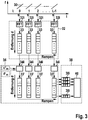
- Fig. 3 shows a block diagram of a method implemented in the signal processing unit 28 for evaluating the baseband signal s.
- a first Fourier transformation 32 takes place in that the sub-signals of the baseband signal s corresponding to the chirps are each subjected to a discrete Fourier transformation 32i in the form of a fast Fourier transformation (FFT) in order to determine a respective complex frequency spectrum 33.
- FFT fast Fourier transformation
- the spectrum 33 contains a peak at a respective frequency position f d .
- the sequence of the chirps 30 results in a harmonic oscillation of the phase of the peak at a constant relative speed v of the located object.
- Their frequency position f v is proportional to the average relative speed v.
- the signal has a phase offset ⁇ m (I) within a ramp 30.
- the one-dimensional frequency spectra 33 are subjected to phase demodulation 34, in which the phase offsets modulated onto the transmission signal are demodulated by opposite phase offsets.
- the ramp index I is demodulated 34i by multiplying the complex spectrum 33 by C * m (I), the conjugate complex of C m (I).
- a second Fourier transformation 38 takes place, for example in the form of a respective FFT 38i, which is carried out for the respective frequency position of the one-dimensional, phase-demodulated spectra 33 ′ corresponding to a distance d via the current ramp index I. Examples are in Fig. 3 the values of the frequency spectra 33 'belonging to a frequency position of the frequency spectra 33' are shown hatched.
- the frequency spectrum calculated with the second FFT shows the peak associated with the respective object at the Doppler frequency f v , corresponding to a peak position (f d , f v ) in the two-dimensional spectrum obtained.
- the further evaluation and object detection is carried out by a detection unit 40.
- the phase demodulation can alternatively take place before the calculation of the first FFT 32.
- the series connection of the first FFT 32 and the second FFT 38 corresponds to a two-dimensional FFT of the phase-demodulated sequence of the radar echoes.
- Fig. 4 1 shows an example in which, by using different code sequences of two FMCW radar sensors 10, 10 'in a motor vehicle 42, self-interference in the form of an interference signal which is received by one radar sensor 10 and comes from the other radar sensor 10' with a transmitting antenna 20 ', is suppressed.
- the radar sensors 10, 10 ' have different installation locations and are in particular mounted separately on the vehicle.
- An interfering signal from a second radar sensor 10 'of the own vehicle is received by an object 46 at a distance of 3.32 m and at a relative speed of 0 m / s, for example a vehicle in front.
- the transmission signals, and in particular the ramp sequences of the radar sensors 10, 10 ′, are synchronized with one another via an on-board vehicle bus system of the motor vehicle 42.
- the first radar sensor 10 uses a code sequence C m for the phase modulation, the second radar sensor 10 'uses a code sequence C q orthogonal thereto.
- the code sequences are also referred to below as codes.
- the cross-correlation function is defined for complex C m , C q as: r Cm .
- I is the time offset and corresponds to the difference between the indices of the values of the respective codes.
- Hadamard codes for example, can be used as orthogonal codes.
- Hadamard codes are binary codes in which the codes of a code set consist of mutually orthogonal lines of Hadamard matrices.
- the elements of a code also referred to as code values, are limited to the values +1 and -1, corresponding to phase offsets of 0 ° and 180 °, respectively.
- the elements of the code can be defined by one bit each.
- the received signal can be regarded as synchronous with the transmitted signal, corresponding to a time offset of zero. This is referred to below as the synchronization condition.
- the correlation sum of the codes is equal to the code length L. This corresponds to the synchronous multiplication of the two codes.
- the cross-correlation function of the two codes for arises as a factor of an amplitude of the second Fourier transformation a time offset equal to zero, r Cm, Cq (0).
- the time offset is equal to 0 when the synchronization condition is fulfilled and the signal originating from the first ramp of the radar sensor 10 ′ is received together with the signal originating from the first ramp of the radar sensor 10.
- the correlation sum is zero.
- an interference signal is a signal originating from the radar sensor 10 ′ and reflected on the object 44.
- interference signals originating directly from the radar sensor 10 ' can also be suppressed. These can correspond, for example, to a dummy object.
- the distance-dependent portion of the frequency dominates in the baseband signal of a ramp, so that the frequency spectrum of the first FFT of a partial signal corresponds to a resolution after the distances d.
- the amplitudes of the frequency spectra of the partial signals are in Fig. 5 schematically plotted over the distance d and over the ramp index I.
- the complex amplitudes in the frequency position of the interfering signal are phase-modulated with the code C q (I).
- the value for the frequency position of the difference signal from the target at a distance of 3.32 m and relative speed 0 m / s is zero, however, since the orthogonality of the codes used results in an amplitude of zero when summing the second FFT.
- An interfering signal from a radar sensor 10 ′′ mounted on the rear of a vehicle 46 in front is received from a distance of 1.66 m at a relative speed of 0 m / s.
- Fig. 7 shows an example of a transmission signal in which a measuring cycle comprises two partial transmission signals 47, 47 'in the form of nested sequences of frequency ramps 30, 30'.
- the two sequences are also referred to below as ramp sets 47, 47 '.
- the frequency ramps 30 and 30' have an identical ramp stroke, ramp slope and center frequency of the ramps.
- the ramp sets can differ from one another, for example, by a different ramp stroke, a different center frequency and / or a different ramp slope. In the example shown, the ramp sets differ only in the different sign of the ramp slope.
- Each ramp set is phase-modulated with an assigned code sequence of a code set, the code sequence assigning a phase offset to each frequency ramp of the sequence.
- the ramp set 47 (ramps 30) is modulated with a code sequence C m1
- the ramp set 47 '(ramps 30') is modulated with a code sequence C m2 .
- Groups of code sets with this property are also referred to as mutually orthogonal.
- L 512 is described below.
- the signal of the radar sensor 10 is encoded with the code set Cm.
- the signal from the external radar sensor 10 "is encoded with a code set Cq.
- the separation can be implemented, for example, by a time offset, different ramp parameters, and / or by polarization of the antennas used for the individual ramp sets.
- a time offset and a different slope in the form of a different sign of the ramp slope are used.
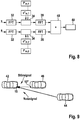
- the processing initially corresponds to that based on Fig. 3 processing explained.
- the first Fourier transformation 32 is carried out.
- a code set is used which correlates with the code set C m1 , C m2 used for the phase modulation, for example is identical here.
- the phase demodulation 34 is carried out by multiplication by the conjugate complex C * m, 1 or C * m, 2 of the respective code, and the second Fourier transformation 38 is carried out via the ramps of the ramp set in question.
- a summation 48 the two-dimensional spectra of the first set of ramps 47 and the second set of ramps 47 'obtained are added and transferred to the detection unit 40 for further evaluation. Since the distance of a target changes only by a very small value during the time offset of the ramp sets 47, 47 ', the complex amplitudes are added coherently when the two-dimensional frequency spectra are summed.
- Fig. 10 schematically shows, via the ramp index I of an individual ramp set 47 or 47 ', the information about the distance d obtained from the first FFT.
- the signal from the external radar sensor is received by the radar sensor 10 5.12 ms later than the radar echo of the target.
- the respective phase demodulations and the second Fourier transformation 38 are then carried out for the frequency spectra of the respective ramp sets 47, 47 '.
- the two ramp sets each have a two-dimensional spectrum over d and v according to Fig. 11 ,
- ⁇ 01 is a phase offset that depends on the distance of the target.
- the interfering signal is effectively suppressed and the real target can be detected on the basis of the two-dimensional spectrum.
- a code set can be chosen randomly from a group of mutually orthogonal codes.
- different values of at least one parameter of the frequency ramps of the ramp sets 47, 47 ' can be used in successive measurement cycles. If, for example, different ramp slopes are used, the probability is increased that an interfering signal has a different ramp slope than the signal of its own radar sensor. The energy of the interfering signal is then distributed over frequencies in the baseband signal and causes a noise background of the useful signal. For example, different durations or numbers of the ramps of the ramp sets and / or different center frequencies can also be used.
- phase modulation and demodulation each take place with the same code, corresponding to a "matched filter” approach
- code f m or a code set f m1 , f m2 instead for the phase demodulation , which correlates with the code C m , but is not identical, the code set f m1 , f m2 with the at least one further Code set C q meets the code set orthogonality condition.
- Fig. 1 . Fig. 3 and Fig. 8 each indicated by dashed lines.
- the codes f m1 , ??, f mQ corresponding to a linear filter are selected, for example, for a number of Q codes of length L of a code set so that they meet the conditions: r fm 1 . Cm 1 0 + r fm 2 . Cm 2 0 + .... + r fmQ .
- CmQ 0 LQ .
- CqQ i 0
- i i
- phase demodulation of the baseband signal can also be carried out before the first FFT, e.g. the phase demodulation with the code sequences of a code set takes place in separate channels.
- Phase demodulation can also be carried out with the code used in the transmission signal, in that the mixer mixes a received signal with the phase-modulated transmission signal in order to generate the baseband signal.
- Multi-value codes can also be used.
- Binary codes allow a simple circuit design, since for a phase offset of 180 ° only the amplitude of the signal has to be inverted.
- a transmission signal can also be modulated with at least one sequence of frequency ramps that is phase and amplitude modulated according to a code sequence.
- orthogonal codes instead of the Hadamard codes described, other orthogonal codes can also be used, for example Fourier codes.
- the described modulation method with frequency ramps of the same center frequency f 0 according to Fig. 2 or Fig. 7 can be modified by, for example, the center frequency f 0 of the respective within a ramp set or a ramp sequence Ramps is changed according to a linear, higher-level frequency ramp with stroke F slow and ramp duration T slow .
- the frequency f v + f d, slow then corresponds to an FMCW equation for the higher-level ramp.
- the codes described have the advantage that they exist for any code length and that the favorable correlation property is available for each code length. This provides great flexibility in the design of radar signals and radar systems. For example, transmission signals with few ramps can be used. This can result in a shorter transmission time and reduced memory requirements and the data transfer rate of the evaluation unit.
- v and d of an object can be determined.
- a functional relationship between v and d can be determined from a first Fourier analysis of a partial signal assigned to a ramp, for example according to the FMCW equation. Information obtained from the second FFT can then be used to determine v and d, for example, and / or values can be matched over several sequences of ramps with different ramp parameters.
- a respective first Fourier transformation of the respective radar echoes of the frequency ramps of the transmission signal can take place; first information from at least one obtained one-dimensional spectrum in the form of a functional relationship between the distance d and the relative speed v of a located one Object can be determined, the different relative speeds v assigns different distances d, for example, the functional relationship can correspond to an FMCW equation for a respective frequency ramp; at least one second Fourier transformation is carried out in a second dimension over the time course of the sequence of the phase-demodulated, one-dimensional spectra of the radar echoes of the successive frequency ramps; From at least one spectrum obtained from the second Fourier transformation, or, in the case of the partial transmission signals, from the summation of the spectra obtained from the second Fourier transformation, further information about the relative speed and optionally the distance of the located object are obtained, the further information being, for example, information in the form can be a functional relationship according to an FMCW equation for the higher-level, slow ramp of the center frequencies of the frequency ramps
- the comparison of the first information with the second information can take place taking into account an ambiguity of the second information determined by a uniqueness range for the relative speed v and optionally the distance d.
- a method is also called multispeed FMCW (MS-FMCW).
- MS-FMCW multispeed FMCW
- the use of the orthogonal codes or code sets which fulfill the orthogonality condition has the particular advantage that even with MS-FMCW modulation patterns with relatively few, comparatively long ramps, very good suppression of self-interference and / or external interference can be achieved. With a reduced sampling rate of the A / D converter, a good separability of the relative speed v can nevertheless be achieved.
- the spectrum of the second Fourier transformation represents a spectrum of a two-dimensional Fourier analysis, or a sum of two such spectra of the partial transmit signals.
- the distance and the relative speed are thus in particular based on a value of the frequency spectrum of a two-dimensional one Fourier analysis determines, or based on a summation of such two-dimensional frequency spectra.
- the first information can already be determined from a one-dimensional spectrum of a first Fourier transformation.
- the first information from the position of the peak in the first dimension of the frequency spectrum can also be determined on the basis of a peak in the two-dimensional frequency spectrum and the further information can be determined from the position of the peak in the second dimension of the frequency spectrum.
- Fig. 13 shows an example of a vd diagram of first and second information of a ramp sequence of an MS-FMCW measurement with a slow, superordinate frequency ramp of the center frequencies of the short ramps.
- a frequency ramp results instead of a value for d, the straight line which is slightly inclined with respect to the vertical, corresponding to a linear relationship between the relative speed v and the distance d (first information).
- the peak of the spectrum of the second FFT (or the peak of the sum of the spectra of the second FFT) results in a further, here flat, dashed straight line, which is ambiguous.
Landscapes
- Engineering & Computer Science (AREA)
- Radar, Positioning & Navigation (AREA)
- Remote Sensing (AREA)
- Computer Networks & Wireless Communication (AREA)
- Physics & Mathematics (AREA)
- General Physics & Mathematics (AREA)
- Electromagnetism (AREA)
- Signal Processing (AREA)
- Radar Systems Or Details Thereof (AREA)
- Traffic Control Systems (AREA)
Applications Claiming Priority (2)
| Application Number | Priority Date | Filing Date | Title |
|---|---|---|---|
| DE102013210256.9A DE102013210256A1 (de) | 2013-06-03 | 2013-06-03 | Interferenzunterdrückung bei einem fmcw-radar |
| PCT/EP2014/057019 WO2014195046A1 (de) | 2013-06-03 | 2014-04-08 | Interferenzunterdrückung bei einem fmcw-radar |
Publications (2)
| Publication Number | Publication Date |
|---|---|
| EP3004918A1 EP3004918A1 (de) | 2016-04-13 |
| EP3004918B1 true EP3004918B1 (de) | 2020-03-04 |
Family
ID=50440670
Family Applications (1)
| Application Number | Title | Priority Date | Filing Date |
|---|---|---|---|
| EP14715624.4A Active EP3004918B1 (de) | 2013-06-03 | 2014-04-08 | Interferenzunterdrückung bei einem fmcw-radar |
Country Status (6)
| Country | Link |
|---|---|
| US (1) | US10048353B2 (enExample) |
| EP (1) | EP3004918B1 (enExample) |
| JP (1) | JP6109416B2 (enExample) |
| CN (1) | CN105264400B (enExample) |
| DE (1) | DE102013210256A1 (enExample) |
| WO (1) | WO2014195046A1 (enExample) |
Cited By (1)
| Publication number | Priority date | Publication date | Assignee | Title |
|---|---|---|---|---|
| CN112435473A (zh) * | 2020-11-14 | 2021-03-02 | 公安部交通管理科学研究所 | 一种结合历史数据的快速路交通流溯源及匝道调控方法 |
Families Citing this family (123)
| Publication number | Priority date | Publication date | Assignee | Title |
|---|---|---|---|---|
| US9594159B2 (en) * | 2013-07-15 | 2017-03-14 | Texas Instruments Incorporated | 2-D object detection in radar applications |
| US9841497B2 (en) * | 2014-06-05 | 2017-12-12 | Infineon Technologies Ag | Method, device and system for processing radar signals |
| DE102014212281A1 (de) * | 2014-06-26 | 2015-12-31 | Robert Bosch Gmbh | Radarmessverfahren mit unterschiedlichen Sichtbereichen |
| DE102014226127A1 (de) * | 2014-12-16 | 2016-06-16 | Robert Bosch Gmbh | Radarsystem, verfahren zum erzeugen eines sendesignals für ein radarsystem und fahrzeug |
| US10725150B2 (en) | 2014-12-23 | 2020-07-28 | Infineon Technologies Ag | System and method for radar |
| EP3056920B1 (en) * | 2015-02-11 | 2020-08-19 | Veoneer Sweden AB | A vehicle radar system with two transceiver arrangements |
| CN104793190A (zh) * | 2015-03-24 | 2015-07-22 | 王方圆 | 基于信道监听机制的多汽车防撞雷达冲突抑制系统 |
| DE102016101041B4 (de) * | 2016-01-21 | 2018-11-22 | Infineon Technologies Ag | Konzept für Car2X-Kommunikation |
| US9846228B2 (en) | 2016-04-07 | 2017-12-19 | Uhnder, Inc. | Software defined automotive radar systems |
| US10261179B2 (en) | 2016-04-07 | 2019-04-16 | Uhnder, Inc. | Software defined automotive radar |
| US9689967B1 (en) * | 2016-04-07 | 2017-06-27 | Uhnder, Inc. | Adaptive transmission and interference cancellation for MIMO radar |
| WO2017187331A1 (en) | 2016-04-25 | 2017-11-02 | Uhnder, Inc. | Vehicle radar system with a shared radar and communication system |
| WO2017187304A2 (en) | 2016-04-25 | 2017-11-02 | Uhnder, Inc. | Digital frequency modulated continuous wave radar using handcrafted constant envelope modulation |
| WO2017187278A1 (en) | 2016-04-25 | 2017-11-02 | Uhnder, Inc. | Pmcw – pmcw interference mitigation |
| JP2017211336A (ja) * | 2016-05-27 | 2017-11-30 | パナソニックIpマネジメント株式会社 | レーダ装置および起動タイミング決定方法 |
| US9753121B1 (en) | 2016-06-20 | 2017-09-05 | Uhnder, Inc. | Power control for improved near-far performance of radar systems |
| US20180011181A1 (en) | 2016-07-07 | 2018-01-11 | Infineon Technologies Ag | Radar systems and methods thereof |
| US11460572B2 (en) | 2016-08-12 | 2022-10-04 | University Of Washington | Millimeter wave imaging systems and methods using direct conversion receivers and/or modulation techniques |
| DE102016216176A1 (de) * | 2016-08-29 | 2018-03-01 | Audi Ag | Verfahren zum Betreiben eines Radarsensors in oder an einem Kraftfahrzeug und Kraftfahrzeug |
| US10379201B2 (en) * | 2016-10-26 | 2019-08-13 | GM Global Technology Operations LLC | Radar interference mitigation and collaborative operation |
| DE102016221947A1 (de) | 2016-11-09 | 2018-05-09 | Robert Bosch Gmbh | Radarsensor für Kraftfahrzeuge |
| WO2018147929A2 (en) | 2016-12-08 | 2018-08-16 | University Of Washington | Millimeter wave and/or microwave imaging systems and methods including examples of partioned inverse and enhanced resolution modes and imaging devices |
| DE102017200383A1 (de) * | 2017-01-11 | 2018-07-12 | Astyx Gmbh | Radarsensor mit zweidimensionaler Strahlschwenkung und L-, U- oder T-förmiger Struktur für den Verbau im Bereich des Front-Kühlers beim Automobil |
| DE102017200317A1 (de) * | 2017-01-11 | 2018-07-12 | Robert Bosch Gmbh | Radarsensor und Verfahren zur Bestimmung einer Relativgeschwindigkeit eines Radarziels |
| DE102017101763A1 (de) * | 2017-01-30 | 2018-08-02 | Valeo Schalter Und Sensoren Gmbh | Verfahren zur Ermittlung von wenigstens einer Objektinformation wenigstens eines Objektes, das mit einem Radarsystem insbesondere eines Fahrzeugs erfasst wird, Radarsystem und Fahrerassistenzsystem |
| US11454697B2 (en) | 2017-02-10 | 2022-09-27 | Uhnder, Inc. | Increasing performance of a receive pipeline of a radar with memory optimization |
| WO2018146530A1 (en) | 2017-02-10 | 2018-08-16 | Uhnder, Inc. | Reduced complexity fft-based correlation for automotive radar |
| WO2018146634A1 (en) | 2017-02-10 | 2018-08-16 | Uhnder, Inc. | Increasing performance of a receive pipeline of a radar with memory optimization |
| DE102017204495A1 (de) * | 2017-03-17 | 2018-09-20 | Robert Bosch Gmbh | Verfahren und Vorrichtung zum Ermitteln von transversalen Relativgeschwindigkeitskomponenten von Radarzielen |
| DE102017105783B4 (de) * | 2017-03-17 | 2020-06-10 | S.M.S Smart Microwave Sensors Gmbh | Verfahren zum Bestimmen eines Abstandes und einer Geschwindigkeit eines Objektes |
| CN110462422B (zh) * | 2017-03-30 | 2023-04-25 | 日立安斯泰莫株式会社 | 雷达装置 |
| DE102017107212A1 (de) * | 2017-04-04 | 2018-10-04 | Infineon Technologies Ag | Verfahren und Vorrichtung zum Verarbeiten von Radarsignalen |
| DE102017207607B4 (de) * | 2017-05-05 | 2025-01-30 | Continental Autonomous Mobility Germany GmbH | Radarsystem mit Überwachung der Frequenzlage einer Folge von gleichartigen Sendesignalen |
| DE102017207604B4 (de) | 2017-05-05 | 2019-11-28 | Conti Temic Microelectronic Gmbh | Radarsystem mit Überwachung der Frequenzmodulation einer Folge von gleichartigen Sendesignalen |
| EP3410150B1 (en) * | 2017-05-30 | 2022-01-19 | Nxp B.V. | Apparatus for detection and ranging |
| WO2018219740A1 (en) * | 2017-06-01 | 2018-12-06 | Iee International Electronics & Engineering S.A. | Method and system for moving target detection, and vehicle incorporating same |
| LU100468B1 (en) * | 2017-10-06 | 2019-04-09 | Iee Sa | Method and system for moving target detection, and vehicle incorporating same |
| DE102017209628A1 (de) * | 2017-06-08 | 2018-12-13 | Robert Bosch Gmbh | FMCW-Radarsensor für Kraftfahrzeuge |
| JP6926775B2 (ja) * | 2017-07-24 | 2021-08-25 | 日本電気株式会社 | 移動目標探知システム及び移動目標探知方法 |
| KR102365932B1 (ko) * | 2017-08-03 | 2022-02-22 | 한국전자통신연구원 | 국부발진 주파수 특성 정합을 위한 레이더 시스템 및 이의 구동방법 |
| DE102017119624A1 (de) | 2017-08-28 | 2019-04-18 | HELLA GmbH & Co. KGaA | Verfahren zum Betrieb eines Radarsystems eines Fahrzeuges |
| KR102401188B1 (ko) * | 2017-08-28 | 2022-05-24 | 삼성전자주식회사 | 차량의 레이더를 이용한 오브젝트 검출 방법 및 장치 |
| DE102017215561A1 (de) * | 2017-09-05 | 2019-03-07 | Robert Bosch Gmbh | FMCW-Radarsensor mit synchronisierten Hochfrequenzbausteinen |
| DE102018123383A1 (de) * | 2017-10-13 | 2019-04-18 | Infineon Technologies Ag | Radarerfassung mit Störungsunterdrückung |
| KR102397095B1 (ko) | 2017-11-17 | 2022-05-12 | 삼성전자주식회사 | 차량의 레이더를 이용한 오브젝트 검출 방법 및 장치 |
| DE102017221257A1 (de) * | 2017-11-28 | 2019-05-29 | Audi Ag | Radarsystem und Verfahren zum Betreiben eines Radarsystems |
| DE102017129149A1 (de) * | 2017-12-07 | 2019-06-13 | Valeo Schalter Und Sensoren Gmbh | Verfahren zur Ermittlung von wenigstens einer Objektinformation wenigstens eines Zielobjekts, das mit einem Radarsystem insbesondere eines Fahrzeugs erfasst wird, Radarsystem und Fahrerassistenzsystem |
| US11105890B2 (en) | 2017-12-14 | 2021-08-31 | Uhnder, Inc. | Frequency modulated signal cancellation in variable power mode for radar applications |
| US10718860B2 (en) * | 2018-01-11 | 2020-07-21 | Infineon Technologies Ag | System and method to improve range accuracy in FMCW radar using FSK modulated chirps |
| US12386029B2 (en) | 2018-01-29 | 2025-08-12 | Robert Bosch Gmbh | Millimeter wave automotive radar systems |
| DE102018201303A1 (de) * | 2018-01-29 | 2019-08-01 | Robert Bosch Gmbh | Verfahren und Vorrichtung zum Betreiben von mehreren Sensoren eines Fahrzeugs |
| DE102018102816B3 (de) * | 2018-02-08 | 2019-07-04 | Infineon Technologies Ag | Radar mit phasenkorrektur |
| DE102018106858A1 (de) * | 2018-03-22 | 2019-09-26 | Infineon Technologies Ag | Fmcw-radar mit zusätzlicher am zur störungsdetektion |
| JP7592492B2 (ja) * | 2018-03-26 | 2024-12-02 | クアルコム,インコーポレイテッド | レーダー情報を交換してマルチレーダー共存を改善するためのサイド通信チャネルの使用 |
| US11644529B2 (en) | 2018-03-26 | 2023-05-09 | Qualcomm Incorporated | Using a side-communication channel for exchanging radar information to improve multi-radar coexistence |
| US10482768B1 (en) * | 2018-05-08 | 2019-11-19 | Denso International America, Inc. | Vehicle function impairment detection |
| JP7131961B2 (ja) * | 2018-05-17 | 2022-09-06 | 株式会社デンソーテン | レーダ装置及び物標ピーク抽出方法 |
| WO2019224950A1 (ja) * | 2018-05-23 | 2019-11-28 | 三菱電機株式会社 | レーダ装置 |
| CN110531358B (zh) * | 2018-05-25 | 2023-07-18 | 华为技术有限公司 | 信息测量方法及信息测量装置 |
| EP3572829B1 (en) * | 2018-05-25 | 2024-01-17 | Airbus Defence and Space GmbH | Synchronized radar networks |
| DE102018208992A1 (de) * | 2018-06-07 | 2019-12-12 | Robert Bosch Gmbh | Radarsensorsystem |
| US11280876B2 (en) * | 2018-06-18 | 2022-03-22 | Qualcomm Incorporated | Multi-radar coexistence using phase-coded frequency modulated continuous wave waveforms |
| DE102018210083A1 (de) * | 2018-06-21 | 2019-12-24 | Robert Bosch Gmbh | Auswertevorrichtung und Verfahren zum Auswerten zumindest eines Radarsensors |
| US11385323B2 (en) | 2018-06-25 | 2022-07-12 | Qualcomm Incorporated | Selection of frequency modulated continuous wave (FMWC) waveform parameters for multi-radar coexistence |
| KR102628655B1 (ko) * | 2018-06-29 | 2024-01-24 | 삼성전자주식회사 | 레이더 구동 장치 및 방법 |
| US11585919B2 (en) * | 2018-07-19 | 2023-02-21 | Qualcomm Incorporated | Multi-radar coexistence using slow rate interference identification and suppression |
| US11585889B2 (en) * | 2018-07-25 | 2023-02-21 | Qualcomm Incorporated | Methods for radar coexistence |
| US11187783B2 (en) * | 2018-08-14 | 2021-11-30 | Nxp B.V. | Radar systems and methods for operating radar systems |
| US11360185B2 (en) * | 2018-10-24 | 2022-06-14 | Infineon Technologies Ag | Phase coded FMCW radar |
| CN109471095B (zh) * | 2018-11-06 | 2023-02-14 | 哈尔滨工程大学 | 一种基于快速迭代插值的fmcw雷达距离估计方法 |
| US11474225B2 (en) | 2018-11-09 | 2022-10-18 | Uhnder, Inc. | Pulse digital mimo radar system |
| DE102018128804A1 (de) * | 2018-11-16 | 2020-05-20 | Valeo Schalter Und Sensoren Gmbh | Verfahren zum Betreiben einer Radarsensorvorrichtung für ein Kraftfahrzeug, bei welchem zwei frequenz-kodierte Radarsignale erzeugt werden, Computerprogrammprodukt, Radarsensorvorrichtung sowie Kraftfahrzeug |
| US11054516B2 (en) * | 2018-12-18 | 2021-07-06 | Nxp Usa, Inc. | Extended doppler FMCW code division MIMO radar |
| US11099267B2 (en) * | 2018-12-18 | 2021-08-24 | Nxp Usa, Inc. | Extended doppler PMCW code division MIMO radar |
| US11204410B2 (en) * | 2019-02-11 | 2021-12-21 | Nxp B.V. | Radar-based communication |
| CN111638519B (zh) * | 2019-03-01 | 2023-03-03 | 华为技术有限公司 | 一种利用无线电信号进行目标物探测的方法及相关装置 |
| WO2020183392A1 (en) | 2019-03-12 | 2020-09-17 | Uhnder, Inc. | Method and apparatus for mitigation of low frequency noise in radar systems |
| CN109870677B (zh) * | 2019-03-13 | 2023-02-24 | 西安工业大学 | 一种调频连续波干涉信号幅度归一化方法 |
| TWI743456B (zh) * | 2019-03-15 | 2021-10-21 | 昇雷科技股份有限公司 | 頻率調變連續波雷達之偵測方法 |
| DE102019203760A1 (de) * | 2019-03-20 | 2020-09-24 | Zf Friedrichshafen Ag | Sensorsystem und Verfahren zum Detektieren von Objekten in einer Umgebung eines Fahrzeugs |
| US11782148B2 (en) * | 2019-03-25 | 2023-10-10 | Texas Instruments Incorporated | Radar system |
| US10778282B1 (en) * | 2019-05-07 | 2020-09-15 | Cisco Technology, Inc. | Methods for improving flexibility and data rate of chirp spread spectrum systems in LoRaWAN |
| CN112014800B (zh) * | 2019-05-31 | 2022-12-02 | 华为技术有限公司 | 一种雷达信号发送方法及设备 |
| US10855328B1 (en) * | 2019-07-03 | 2020-12-01 | Qualcomm Incorporated | Interference suppression for multi-radar coexistence |
| WO2021004625A1 (en) * | 2019-07-09 | 2021-01-14 | Nokia Technologies Oy | Obstacle detection techniques for telecommmunications systems |
| CN110581818B (zh) * | 2019-08-06 | 2022-01-04 | 北京遥测技术研究所 | 一种随机截断线性调频连续波信号的生成系统及方法 |
| DE102019215107A1 (de) * | 2019-09-27 | 2021-04-01 | Robert Bosch Gmbh | Verfahren und Vorrichtung zum Aussenden elektromagnetischer Strahlung und Empfangen von den Objekten reflektierter Teilstrahlung |
| DE102019214949A1 (de) * | 2019-09-27 | 2021-04-01 | Robert Bosch Gmbh | Verfahren und Vorrichtung zum Erkennen eines absorptiven Radombelags |
| US11754669B2 (en) * | 2019-09-30 | 2023-09-12 | Qualcomm Incorporated | Radar coordination for multi-radar coexistence |
| CN112578342B (zh) | 2019-09-30 | 2025-01-14 | 深圳引望智能技术有限公司 | 一种信号发送方法、信号处理方法及雷达装置 |
| WO2021086525A1 (en) * | 2019-10-31 | 2021-05-06 | Intel Corporation | Systems, devices, and methods for synchronization |
| DE102019217066A1 (de) * | 2019-11-06 | 2021-05-06 | Robert Bosch Gmbh | Verfahren für einen störungsarmen Betrieb mehrerer Radarsensoren |
| TWI734252B (zh) * | 2019-11-08 | 2021-07-21 | 立積電子股份有限公司 | 雷達及雷達回波訊號的背景成分更新方法 |
| DE102019133977A1 (de) | 2019-12-11 | 2021-06-17 | Valeo Schalter Und Sensoren Gmbh | Verfahren zur Ermittlung von wenigstens einer Objektinformation wenigstens eines Objektes, das mit einem Radarsystem erfasst wird und Radarsystem |
| DE102019219640A1 (de) * | 2019-12-14 | 2021-06-17 | Robert Bosch Gmbh | Radarmodul, Radarsystem und Verfahren zum Betreiben eines Radarmoduls |
| US11899126B2 (en) | 2020-01-13 | 2024-02-13 | Uhnder, Inc. | Method and system for multi-chip operation of radar systems |
| KR102847657B1 (ko) | 2020-03-17 | 2025-08-20 | 선전 인왕 인텔리전트 테크놀로지스 컴퍼니 리미티드 | 신호 처리 방법 및 장치, 및 저장 매체 |
| DE102020107372A1 (de) * | 2020-03-18 | 2021-09-23 | HELLA GmbH & Co. KGaA | Verfahren zum Betreiben eines Radarsystems |
| EP3883144B1 (en) * | 2020-03-18 | 2022-12-07 | Airbus Defence and Space GmbH | Method for synchronizing wireless network nodes and wireless communication network |
| US11550027B2 (en) | 2020-05-04 | 2023-01-10 | Nxp B.V. | Predistortion technique for joint radar/communication systems |
| CN113625240B (zh) * | 2020-05-06 | 2022-05-24 | 华为技术有限公司 | 信号探测方法、装置和雷达系统 |
| KR102653404B1 (ko) * | 2020-05-08 | 2024-04-02 | 주식회사 에이치엘클레무브 | 차량의 제어 장치 및 제어 방법 |
| CN114660544A (zh) * | 2020-05-30 | 2022-06-24 | 华为技术有限公司 | 一种雷达信号发射和接收方法及装置 |
| CN111693961B (zh) * | 2020-06-15 | 2023-05-16 | 哈尔滨工业大学 | 一种基于kl散度单元筛选的cfar检测器 |
| DE102020210079B3 (de) | 2020-08-10 | 2021-08-19 | Conti Temic Microelectronic Gmbh | Radarverfahren sowie Radarsystem mit hoher Entfernungsauflösung bei geringem Signalprozessierungsaufwand |
| CN111983597B (zh) * | 2020-08-28 | 2024-10-11 | 北京经纬恒润科技股份有限公司 | 调频连续波雷达发射波控制方法及装置 |
| US11693107B2 (en) * | 2020-09-29 | 2023-07-04 | Steradian Semiconductors Private Limited | System, device and method for efficient MIMO radar |
| US11733346B2 (en) * | 2021-02-24 | 2023-08-22 | Qualcomm Incorporated | Assistance information to aid with cooperative radar sensing with imperfect synchronization |
| CN115134030A (zh) * | 2021-03-29 | 2022-09-30 | 东风汽车集团股份有限公司 | 车载多传感器同步方法、装置、设备和存储介质 |
| KR102628228B1 (ko) * | 2021-06-15 | 2024-01-23 | 현대모비스 주식회사 | 레이더 신호 처리 시스템 및 처리 방법 |
| JP7433528B2 (ja) * | 2021-06-21 | 2024-02-19 | 三菱電機株式会社 | レーダ装置および干渉波抑圧装置 |
| CN113687344B (zh) * | 2021-07-20 | 2023-08-11 | 西安空间无线电技术研究所 | 一种三角波调制线性调频连续波雷达测速方法 |
| TWI802994B (zh) * | 2021-09-17 | 2023-05-21 | 為昇科科技股份有限公司 | 雷達測速系統、方法及雷達裝置 |
| US12007465B2 (en) | 2021-10-19 | 2024-06-11 | Nxp B.V. | Radar apparatus and method with content embedded in the radar signal |
| KR102763801B1 (ko) * | 2021-11-29 | 2025-02-07 | 주식회사 산엔지니어링 | 디지털 직교 코드를 이용한 레이더 시스템 |
| US12196843B2 (en) | 2022-05-26 | 2025-01-14 | Waymo Llc | Methods and systems for radar waveform diversity |
| EP4530669A4 (en) * | 2022-06-13 | 2025-09-24 | Huawei Tech Co Ltd | DETECTION METHOD, COMMUNICATION APPARATUS AND COMMUNICATION SYSTEM |
| DE102022209859A1 (de) * | 2022-09-20 | 2024-03-21 | Continental Autonomous Mobility Germany GmbH | Verfahren zum Fokussieren der Radarerfassung für eine Relativbewegung |
| DE102022211688A1 (de) * | 2022-11-07 | 2024-05-08 | Robert Bosch Gesellschaft mit beschränkter Haftung | Radarverfahren und Radarvorrichtung |
| US12386026B2 (en) * | 2022-12-20 | 2025-08-12 | GM Global Technology Operations LLC | Method and system of time-frequency sensor coding for interference mitigation in a vehicle |
| WO2024254751A1 (en) * | 2023-06-13 | 2024-12-19 | Huawei Technologies Co., Ltd. | Methods, apparatuses, and devices for communication in integrated sensing and communication systems |
| CN118129849A (zh) * | 2024-05-08 | 2024-06-04 | 杭州开闳流体科技有限公司 | 应用正交编码测量信号的时差法流量计测试方法及其应用 |
| CN118884448B (zh) * | 2024-08-22 | 2025-09-09 | 中国人民解放军海军工程大学 | 一种多接收阵合成孔径声纳成像方法及系统 |
Citations (1)
| Publication number | Priority date | Publication date | Assignee | Title |
|---|---|---|---|---|
| WO2010000252A2 (de) * | 2008-07-02 | 2010-01-07 | Adc Automotive Distance Control Systems Gmbh | Radarsystem mit verbesserter winkelbildung |
Family Cites Families (17)
| Publication number | Priority date | Publication date | Assignee | Title |
|---|---|---|---|---|
| JP3196536B2 (ja) | 1994-11-22 | 2001-08-06 | 松下電器産業株式会社 | レーダ装置 |
| JP3397158B2 (ja) * | 1999-01-20 | 2003-04-14 | 三菱電機株式会社 | Ecmレーダ装置 |
| DE10100417A1 (de) | 2001-01-08 | 2002-07-11 | Bosch Gmbh Robert | Radareinrichtung und Verfahren zum Codieren einer Radareinrichtung |
| WO2003104833A2 (en) | 2002-06-06 | 2003-12-18 | Roadeye Flr General Partnership | Forward-looking radar system |
| US7151483B2 (en) | 2004-05-03 | 2006-12-19 | Raytheon Company | System and method for concurrent operation of multiple radar or active sonar systems on a common frequency |
| DE102005048209A1 (de) * | 2005-09-29 | 2007-04-05 | Valeo Schalter Und Sensoren Gmbh | Kraftfahrzeug-Radarverfahren und -Radarsystem |
| DE102006032539A1 (de) | 2006-07-13 | 2008-01-17 | Robert Bosch Gmbh | FMCW-Radarsensor |
| US7787819B2 (en) * | 2006-08-25 | 2010-08-31 | Space Systems / Loral, Inc. | Ground-based beamforming for satellite communications systems |
| JP5019316B2 (ja) | 2007-04-26 | 2012-09-05 | 三菱電機株式会社 | Fm−cw偏波レーダ装置 |
| JP4724694B2 (ja) * | 2007-08-08 | 2011-07-13 | 日立オートモティブシステムズ株式会社 | 電波レーダ装置 |
| US8026843B2 (en) | 2008-01-31 | 2011-09-27 | Infineon Technologies Ag | Radar methods and systems using ramp sequences |
| GB2462148A (en) | 2008-07-31 | 2010-02-03 | Mitsubishi Electric Inf Tech | Automotive FMCW radar with multiple frequency chirps |
| EP2629113B1 (de) * | 2009-04-06 | 2017-04-26 | Conti Temic microelectronic GmbH | Radarsystem mit anordnungen und verfahren zur entkopplung von sende- und empfangssignalen sowie unterdrückung von störeinstrahlungen |
| DE102009045141A1 (de) | 2009-09-30 | 2011-03-31 | Robert Bosch Gmbh | Radarsensor mit IQ-Empfänger |
| DE102010024328B4 (de) | 2010-06-18 | 2017-12-07 | Audi Ag | Radarvorrichtung mit situationsadaptiver Modulationsumschaltung und Steuerungsverfahren |
| DE102012008350A1 (de) | 2012-04-19 | 2013-10-24 | S.M.S Smart Microwave Sensors Gmbh | Verfahren und Vorrichtung zur Abstimmung von Abstand und Radialgeschwindigkeit eines Objekts mittels Radarsignalen |
| DE102012212888A1 (de) | 2012-07-23 | 2014-01-23 | Robert Bosch Gmbh | Detektion von Radarobjekten mit einem Radarsensor eines Kraftfahrzeugs |
-
2013
- 2013-06-03 DE DE102013210256.9A patent/DE102013210256A1/de not_active Withdrawn
-
2014
- 2014-04-08 WO PCT/EP2014/057019 patent/WO2014195046A1/de not_active Ceased
- 2014-04-08 CN CN201480031924.6A patent/CN105264400B/zh active Active
- 2014-04-08 JP JP2016515684A patent/JP6109416B2/ja active Active
- 2014-04-08 US US14/895,810 patent/US10048353B2/en active Active
- 2014-04-08 EP EP14715624.4A patent/EP3004918B1/de active Active
Patent Citations (1)
| Publication number | Priority date | Publication date | Assignee | Title |
|---|---|---|---|---|
| WO2010000252A2 (de) * | 2008-07-02 | 2010-01-07 | Adc Automotive Distance Control Systems Gmbh | Radarsystem mit verbesserter winkelbildung |
Cited By (2)
| Publication number | Priority date | Publication date | Assignee | Title |
|---|---|---|---|---|
| CN112435473A (zh) * | 2020-11-14 | 2021-03-02 | 公安部交通管理科学研究所 | 一种结合历史数据的快速路交通流溯源及匝道调控方法 |
| CN112435473B (zh) * | 2020-11-14 | 2022-05-27 | 公安部交通管理科学研究所 | 一种结合历史数据的快速路交通流溯源及匝道调控方法 |
Also Published As
| Publication number | Publication date |
|---|---|
| CN105264400B (zh) | 2018-11-13 |
| US20160124075A1 (en) | 2016-05-05 |
| JP6109416B2 (ja) | 2017-04-05 |
| US10048353B2 (en) | 2018-08-14 |
| EP3004918A1 (de) | 2016-04-13 |
| JP2016524143A (ja) | 2016-08-12 |
| CN105264400A (zh) | 2016-01-20 |
| DE102013210256A1 (de) | 2014-12-04 |
| WO2014195046A1 (de) | 2014-12-11 |
Similar Documents
| Publication | Publication Date | Title |
|---|---|---|
| EP3004918B1 (de) | Interferenzunterdrückung bei einem fmcw-radar | |
| EP3014297B1 (de) | Winkelauflösender fmcw-radarsensor | |
| EP2755045B1 (de) | Verfahren zur zyklischen Messung von Abständen und Geschwindigkeiten von Objekten mit einem FMCW-Radarsensor | |
| EP2948789B1 (de) | Fmcw-radar mit abstandsbereichseinteilung | |
| EP3161510B1 (de) | Radarmessverfahren | |
| DE112007003175B4 (de) | Elektronisch abtastendes Radarsystem | |
| DE102020111533A1 (de) | Mimo-radar-vorrichtungen und mimo-radar-verfahren | |
| EP3155444B1 (de) | Verfahren zur objektortung mit einem fmcw-radar | |
| DE102018221085A1 (de) | Mehrdeutigkeitsauflösung für MIMO-Radarsystem | |
| DE102019112469A1 (de) | Auflösen von doppler-mehrdeutigkeiten in einem multi-input-multi-output-radar unter verwendung digitaler mehrfach-impulsfolgefrequenzen | |
| WO2018086783A1 (de) | Radarsensor für kraftfahrzeuge | |
| WO2017084661A1 (de) | Radarsystem mit verschachtelt seriellem senden und parallelem empfangen | |
| DE102020202498A1 (de) | MIMO-Radarsystem | |
| DE10104022A1 (de) | Radareinrichtung und Verfahren zum Codieren einer Radareinrichtung | |
| WO2015197223A1 (de) | Radarmessverfahren mit unterschiedlichen sichtbereichen | |
| DE102012212888A1 (de) | Detektion von Radarobjekten mit einem Radarsensor eines Kraftfahrzeugs | |
| DE102017200317A1 (de) | Radarsensor und Verfahren zur Bestimmung einer Relativgeschwindigkeit eines Radarziels | |
| EP3803444A1 (de) | Radarsensorsystem | |
| DE102010048896B4 (de) | Verfahren und Vorrichtung zur Umfelderfassung eines Fahrzeugs mit einem Radarsensor | |
| DE102022106791A1 (de) | Mimo-radarvorrichtung und mimo-radarverfahren | |
| DE102011120244A1 (de) | Empfängerarchitektur für orthogonale, Multiple-Input-Multiple-Output Radarsysteme | |
| WO2019110487A1 (de) | Verfahren zur verbesserten zieltrennung unter anwendung phasenkodierter fmcw-rampen verschiedener sender eines kfz-radarsystems | |
| DE102013216461A1 (de) | Synthetik-Apertur-Radarverfahren | |
| DE102024202475A1 (de) | Vorrichtung und verfahren zur verarbeitung von radarsignalen, und radarsystem mit denselben | |
| DE102017208789A1 (de) | Verfahren und Vorrichtung zur Ermittlung zumindest eines Parameters eines Objektes mittels Radar |
Legal Events
| Date | Code | Title | Description |
|---|---|---|---|
| PUAI | Public reference made under article 153(3) epc to a published international application that has entered the european phase |
Free format text: ORIGINAL CODE: 0009012 |
|
| 17P | Request for examination filed |
Effective date: 20160104 |
|
| AK | Designated contracting states |
Kind code of ref document: A1 Designated state(s): AL AT BE BG CH CY CZ DE DK EE ES FI FR GB GR HR HU IE IS IT LI LT LU LV MC MK MT NL NO PL PT RO RS SE SI SK SM TR |
|
| AX | Request for extension of the european patent |
Extension state: BA ME |
|
| DAX | Request for extension of the european patent (deleted) | ||
| STAA | Information on the status of an ep patent application or granted ep patent |
Free format text: STATUS: EXAMINATION IS IN PROGRESS |
|
| 17Q | First examination report despatched |
Effective date: 20180503 |
|
| GRAP | Despatch of communication of intention to grant a patent |
Free format text: ORIGINAL CODE: EPIDOSNIGR1 |
|
| STAA | Information on the status of an ep patent application or granted ep patent |
Free format text: STATUS: GRANT OF PATENT IS INTENDED |
|
| INTG | Intention to grant announced |
Effective date: 20191203 |
|
| GRAS | Grant fee paid |
Free format text: ORIGINAL CODE: EPIDOSNIGR3 |
|
| GRAA | (expected) grant |
Free format text: ORIGINAL CODE: 0009210 |
|
| STAA | Information on the status of an ep patent application or granted ep patent |
Free format text: STATUS: THE PATENT HAS BEEN GRANTED |
|
| AK | Designated contracting states |
Kind code of ref document: B1 Designated state(s): AL AT BE BG CH CY CZ DE DK EE ES FI FR GB GR HR HU IE IS IT LI LT LU LV MC MK MT NL NO PL PT RO RS SE SI SK SM TR |
|
| REG | Reference to a national code |
Ref country code: GB Ref legal event code: FG4D Free format text: NOT ENGLISH |
|
| REG | Reference to a national code |
Ref country code: CH Ref legal event code: EP |
|
| REG | Reference to a national code |
Ref country code: AT Ref legal event code: REF Ref document number: 1241029 Country of ref document: AT Kind code of ref document: T Effective date: 20200315 |
|
| REG | Reference to a national code |
Ref country code: DE Ref legal event code: R096 Ref document number: 502014013742 Country of ref document: DE |
|
| REG | Reference to a national code |
Ref country code: IE Ref legal event code: FG4D Free format text: LANGUAGE OF EP DOCUMENT: GERMAN |
|
| RAP2 | Party data changed (patent owner data changed or rights of a patent transferred) |
Owner name: ROBERT BOSCH GMBH |
|
| REG | Reference to a national code |
Ref country code: SE Ref legal event code: TRGR |
|
| PG25 | Lapsed in a contracting state [announced via postgrant information from national office to epo] |
Ref country code: NO Free format text: LAPSE BECAUSE OF FAILURE TO SUBMIT A TRANSLATION OF THE DESCRIPTION OR TO PAY THE FEE WITHIN THE PRESCRIBED TIME-LIMIT Effective date: 20200604 Ref country code: FI Free format text: LAPSE BECAUSE OF FAILURE TO SUBMIT A TRANSLATION OF THE DESCRIPTION OR TO PAY THE FEE WITHIN THE PRESCRIBED TIME-LIMIT Effective date: 20200304 Ref country code: RS Free format text: LAPSE BECAUSE OF FAILURE TO SUBMIT A TRANSLATION OF THE DESCRIPTION OR TO PAY THE FEE WITHIN THE PRESCRIBED TIME-LIMIT Effective date: 20200304 |
|
| PGFP | Annual fee paid to national office [announced via postgrant information from national office to epo] |
Ref country code: FR Payment date: 20200429 Year of fee payment: 7 |
|
| REG | Reference to a national code |
Ref country code: NL Ref legal event code: MP Effective date: 20200304 |
|
| PG25 | Lapsed in a contracting state [announced via postgrant information from national office to epo] |
Ref country code: BG Free format text: LAPSE BECAUSE OF FAILURE TO SUBMIT A TRANSLATION OF THE DESCRIPTION OR TO PAY THE FEE WITHIN THE PRESCRIBED TIME-LIMIT Effective date: 20200604 Ref country code: GR Free format text: LAPSE BECAUSE OF FAILURE TO SUBMIT A TRANSLATION OF THE DESCRIPTION OR TO PAY THE FEE WITHIN THE PRESCRIBED TIME-LIMIT Effective date: 20200605 Ref country code: LV Free format text: LAPSE BECAUSE OF FAILURE TO SUBMIT A TRANSLATION OF THE DESCRIPTION OR TO PAY THE FEE WITHIN THE PRESCRIBED TIME-LIMIT Effective date: 20200304 Ref country code: HR Free format text: LAPSE BECAUSE OF FAILURE TO SUBMIT A TRANSLATION OF THE DESCRIPTION OR TO PAY THE FEE WITHIN THE PRESCRIBED TIME-LIMIT Effective date: 20200304 |
|
| PGFP | Annual fee paid to national office [announced via postgrant information from national office to epo] |
Ref country code: SE Payment date: 20200429 Year of fee payment: 7 Ref country code: GB Payment date: 20200429 Year of fee payment: 7 |
|
| REG | Reference to a national code |
Ref country code: LT Ref legal event code: MG4D |
|
| PG25 | Lapsed in a contracting state [announced via postgrant information from national office to epo] |
Ref country code: NL Free format text: LAPSE BECAUSE OF FAILURE TO SUBMIT A TRANSLATION OF THE DESCRIPTION OR TO PAY THE FEE WITHIN THE PRESCRIBED TIME-LIMIT Effective date: 20200304 |
|
| PG25 | Lapsed in a contracting state [announced via postgrant information from national office to epo] |
Ref country code: LT Free format text: LAPSE BECAUSE OF FAILURE TO SUBMIT A TRANSLATION OF THE DESCRIPTION OR TO PAY THE FEE WITHIN THE PRESCRIBED TIME-LIMIT Effective date: 20200304 Ref country code: ES Free format text: LAPSE BECAUSE OF FAILURE TO SUBMIT A TRANSLATION OF THE DESCRIPTION OR TO PAY THE FEE WITHIN THE PRESCRIBED TIME-LIMIT Effective date: 20200304 Ref country code: CZ Free format text: LAPSE BECAUSE OF FAILURE TO SUBMIT A TRANSLATION OF THE DESCRIPTION OR TO PAY THE FEE WITHIN THE PRESCRIBED TIME-LIMIT Effective date: 20200304 Ref country code: SK Free format text: LAPSE BECAUSE OF FAILURE TO SUBMIT A TRANSLATION OF THE DESCRIPTION OR TO PAY THE FEE WITHIN THE PRESCRIBED TIME-LIMIT Effective date: 20200304 Ref country code: IS Free format text: LAPSE BECAUSE OF FAILURE TO SUBMIT A TRANSLATION OF THE DESCRIPTION OR TO PAY THE FEE WITHIN THE PRESCRIBED TIME-LIMIT Effective date: 20200704 Ref country code: RO Free format text: LAPSE BECAUSE OF FAILURE TO SUBMIT A TRANSLATION OF THE DESCRIPTION OR TO PAY THE FEE WITHIN THE PRESCRIBED TIME-LIMIT Effective date: 20200304 Ref country code: PT Free format text: LAPSE BECAUSE OF FAILURE TO SUBMIT A TRANSLATION OF THE DESCRIPTION OR TO PAY THE FEE WITHIN THE PRESCRIBED TIME-LIMIT Effective date: 20200729 Ref country code: SM Free format text: LAPSE BECAUSE OF FAILURE TO SUBMIT A TRANSLATION OF THE DESCRIPTION OR TO PAY THE FEE WITHIN THE PRESCRIBED TIME-LIMIT Effective date: 20200304 Ref country code: EE Free format text: LAPSE BECAUSE OF FAILURE TO SUBMIT A TRANSLATION OF THE DESCRIPTION OR TO PAY THE FEE WITHIN THE PRESCRIBED TIME-LIMIT Effective date: 20200304 |
|
| REG | Reference to a national code |
Ref country code: CH Ref legal event code: PL |
|
| REG | Reference to a national code |
Ref country code: DE Ref legal event code: R097 Ref document number: 502014013742 Country of ref document: DE |
|
| PG25 | Lapsed in a contracting state [announced via postgrant information from national office to epo] |
Ref country code: MC Free format text: LAPSE BECAUSE OF FAILURE TO SUBMIT A TRANSLATION OF THE DESCRIPTION OR TO PAY THE FEE WITHIN THE PRESCRIBED TIME-LIMIT Effective date: 20200304 |
|
| PLBE | No opposition filed within time limit |
Free format text: ORIGINAL CODE: 0009261 |
|
| STAA | Information on the status of an ep patent application or granted ep patent |
Free format text: STATUS: NO OPPOSITION FILED WITHIN TIME LIMIT |
|
| PG25 | Lapsed in a contracting state [announced via postgrant information from national office to epo] |
Ref country code: CH Free format text: LAPSE BECAUSE OF NON-PAYMENT OF DUE FEES Effective date: 20200430 Ref country code: LU Free format text: LAPSE BECAUSE OF NON-PAYMENT OF DUE FEES Effective date: 20200408 Ref country code: LI Free format text: LAPSE BECAUSE OF NON-PAYMENT OF DUE FEES Effective date: 20200430 Ref country code: DK Free format text: LAPSE BECAUSE OF FAILURE TO SUBMIT A TRANSLATION OF THE DESCRIPTION OR TO PAY THE FEE WITHIN THE PRESCRIBED TIME-LIMIT Effective date: 20200304 Ref country code: IT Free format text: LAPSE BECAUSE OF FAILURE TO SUBMIT A TRANSLATION OF THE DESCRIPTION OR TO PAY THE FEE WITHIN THE PRESCRIBED TIME-LIMIT Effective date: 20200304 |
|
| REG | Reference to a national code |
Ref country code: BE Ref legal event code: MM Effective date: 20200430 |
|
| 26N | No opposition filed |
Effective date: 20201207 |
|
| PG25 | Lapsed in a contracting state [announced via postgrant information from national office to epo] |
Ref country code: BE Free format text: LAPSE BECAUSE OF NON-PAYMENT OF DUE FEES Effective date: 20200430 Ref country code: SI Free format text: LAPSE BECAUSE OF FAILURE TO SUBMIT A TRANSLATION OF THE DESCRIPTION OR TO PAY THE FEE WITHIN THE PRESCRIBED TIME-LIMIT Effective date: 20200304 Ref country code: PL Free format text: LAPSE BECAUSE OF FAILURE TO SUBMIT A TRANSLATION OF THE DESCRIPTION OR TO PAY THE FEE WITHIN THE PRESCRIBED TIME-LIMIT Effective date: 20200304 |
|
| PG25 | Lapsed in a contracting state [announced via postgrant information from national office to epo] |
Ref country code: IE Free format text: LAPSE BECAUSE OF NON-PAYMENT OF DUE FEES Effective date: 20200408 |
|
| REG | Reference to a national code |
Ref country code: AT Ref legal event code: MM01 Ref document number: 1241029 Country of ref document: AT Kind code of ref document: T Effective date: 20200408 |
|
| PG25 | Lapsed in a contracting state [announced via postgrant information from national office to epo] |
Ref country code: AT Free format text: LAPSE BECAUSE OF NON-PAYMENT OF DUE FEES Effective date: 20200408 |
|
| REG | Reference to a national code |
Ref country code: SE Ref legal event code: EUG |
|
| GBPC | Gb: european patent ceased through non-payment of renewal fee |
Effective date: 20210408 |
|
| PG25 | Lapsed in a contracting state [announced via postgrant information from national office to epo] |
Ref country code: GB Free format text: LAPSE BECAUSE OF NON-PAYMENT OF DUE FEES Effective date: 20210408 Ref country code: FR Free format text: LAPSE BECAUSE OF NON-PAYMENT OF DUE FEES Effective date: 20210430 Ref country code: SE Free format text: LAPSE BECAUSE OF NON-PAYMENT OF DUE FEES Effective date: 20210409 |
|
| PG25 | Lapsed in a contracting state [announced via postgrant information from national office to epo] |
Ref country code: TR Free format text: LAPSE BECAUSE OF FAILURE TO SUBMIT A TRANSLATION OF THE DESCRIPTION OR TO PAY THE FEE WITHIN THE PRESCRIBED TIME-LIMIT Effective date: 20200304 Ref country code: MT Free format text: LAPSE BECAUSE OF FAILURE TO SUBMIT A TRANSLATION OF THE DESCRIPTION OR TO PAY THE FEE WITHIN THE PRESCRIBED TIME-LIMIT Effective date: 20200304 Ref country code: CY Free format text: LAPSE BECAUSE OF FAILURE TO SUBMIT A TRANSLATION OF THE DESCRIPTION OR TO PAY THE FEE WITHIN THE PRESCRIBED TIME-LIMIT Effective date: 20200304 |
|
| PG25 | Lapsed in a contracting state [announced via postgrant information from national office to epo] |
Ref country code: MK Free format text: LAPSE BECAUSE OF FAILURE TO SUBMIT A TRANSLATION OF THE DESCRIPTION OR TO PAY THE FEE WITHIN THE PRESCRIBED TIME-LIMIT Effective date: 20200304 Ref country code: AL Free format text: LAPSE BECAUSE OF FAILURE TO SUBMIT A TRANSLATION OF THE DESCRIPTION OR TO PAY THE FEE WITHIN THE PRESCRIBED TIME-LIMIT Effective date: 20200304 |
|
| PGFP | Annual fee paid to national office [announced via postgrant information from national office to epo] |
Ref country code: DE Payment date: 20250624 Year of fee payment: 12 |