EP3004490B1 - Anordnung und verfahren zur verstärkung von tragstrukturen - Google Patents
Anordnung und verfahren zur verstärkung von tragstrukturen Download PDFInfo
- Publication number
- EP3004490B1 EP3004490B1 EP14728978.9A EP14728978A EP3004490B1 EP 3004490 B1 EP3004490 B1 EP 3004490B1 EP 14728978 A EP14728978 A EP 14728978A EP 3004490 B1 EP3004490 B1 EP 3004490B1
- Authority
- EP
- European Patent Office
- Prior art keywords
- bore
- fiber bundle
- grooves
- supporting structure
- support structure
- Prior art date
- Legal status (The legal status is an assumption and is not a legal conclusion. Google has not performed a legal analysis and makes no representation as to the accuracy of the status listed.)
- Active
Links
Images


Classifications
-
- E—FIXED CONSTRUCTIONS
- E04—BUILDING
- E04G—SCAFFOLDING; FORMS; SHUTTERING; BUILDING IMPLEMENTS OR AIDS, OR THEIR USE; HANDLING BUILDING MATERIALS ON THE SITE; REPAIRING, BREAKING-UP OR OTHER WORK ON EXISTING BUILDINGS
- E04G23/00—Working measures on existing buildings
- E04G23/02—Repairing, e.g. filling cracks; Restoring; Altering; Enlarging
- E04G23/0218—Increasing or restoring the load-bearing capacity of building construction elements
-
- E—FIXED CONSTRUCTIONS
- E04—BUILDING
- E04C—STRUCTURAL ELEMENTS; BUILDING MATERIALS
- E04C5/00—Reinforcing elements, e.g. for concrete; Auxiliary elements therefor
- E04C5/07—Reinforcing elements of material other than metal, e.g. of glass, of plastics, or not exclusively made of metal
-
- E—FIXED CONSTRUCTIONS
- E04—BUILDING
- E04G—SCAFFOLDING; FORMS; SHUTTERING; BUILDING IMPLEMENTS OR AIDS, OR THEIR USE; HANDLING BUILDING MATERIALS ON THE SITE; REPAIRING, BREAKING-UP OR OTHER WORK ON EXISTING BUILDINGS
- E04G23/00—Working measures on existing buildings
- E04G23/02—Repairing, e.g. filling cracks; Restoring; Altering; Enlarging
- E04G23/0218—Increasing or restoring the load-bearing capacity of building construction elements
- E04G2023/0251—Increasing or restoring the load-bearing capacity of building construction elements by using fiber reinforced plastic elements
- E04G2023/0262—Devices specifically adapted for anchoring the fiber reinforced plastic elements, e.g. to avoid peeling off
Definitions
- the invention relates to the field of reinforcement of support structures, preferably by applying surface reinforcement, in particular the introduction of force into the surface reinforcement.
- a widely used method is to introduce fiber bundles into a bore in the support structure and to anchor them there and to spread out or fan out an end of the fiber bundle projecting beyond the surface and to stick it to the surface.
- a surface reinforcement can then be glued to the reinforced structural surface.
- the surface reinforcement may first be glued to the structural surface, so that when an anchor attached thereto from a fiber bundle, the protruding end of this is glued to the surface of the surface reinforcement.
- the near-surface potential fracture surface of each anchor is broken at only one point (at the shank).
- the resistance of this potential fracture surface is thus increased only to a limited extent.
- the transmission of force from the fibers of the fiber bundle spread on the surface to the fibers of the fabric is not optimal.
- the very thin, formed by the fibers of the fiber bundle on the surface fiber composite material can be charged only in the pulling direction substantially.
- the fiber composite material buckles, but when subjected to thrust and bending, only very small forces can be transmitted. Therefore, only the approximately in the pulling direction of the surface reinforcement fibers are fully effective. These make up only a small part of the fiber bundle cross-section and cover only a small part of the width of the surface reinforcement.
- the object of the present invention is therefore to provide an arrangement and a method according to which an improvement in the introduction of force into a surface reinforcement is to be achieved.
- the core of the invention is therefore an assembly comprising a support structure having a surface consisting of one or more surfaces, wherein extending from at least one surface of a bore in an inner region of the support structure, and this bore with an adhesive and with a portion of a via this bore protruding fiber bundle is filled, wherein the support structure is provided on the at least one surface, from which the bore extends in an inner region of the support structure, with a plurality of grooves extending from the bore in a region of at least one circular sector and the protruding part of the fiber bundle divided into fiber strands at least partially located in the grooves and is secured therein with the adhesive.
- a support structure here is an element or part of an element referred to which is exposed to forces.
- the support structure is a building or component of a building, such as a slab, ceiling, wall, pillar, rib, beam or the like.
- the support structure is typically made of concrete, especially reinforced concrete, but may also consist of bricks or other bricks, wood, steel or other materials and any combination of these materials.
- the buildings are civil engineering works, such as houses, bridges, tunnels, dams, sports facilities, etc.
- the fiber bundle is a loose arrangement of substantially rectified individual fibers or filaments, in particular of carbon (carbon), glass, basalt, aramid, steel or other inorganic or organic materials.
- the fibers are carbon fibers.
- the thickness of the fiber bundle depends on the area of use and on the forces which are to be transmitted through the fiber bundle. If the fiber bundle consists of carbon fibers, this comprises, in particular, 1000 to 50,000 individual fibers, each themselves having a diameter in the range from 5 to 10 have ⁇ m.
- a typical fiber bundle preferably has a cross-sectional area of from 20 to 70 mm 2 , in particular from 25 to 40 mm 2 .
- the attachment of the fiber bundle to the support structure is typically carried out by attaching, in a first step, at the desired location, a bore which serves to receive a portion of the fiber bundle.
- the bore can be created by any means, such means are well known to those skilled.
- the dimensions of the bore resulting from the strength and the length of the fiber bundle and this in turn of the requirements that are imposed on the inventive arrangement.
- a suitable bore has a diameter of 1 to 5 cm, in particular 1.5 to 3 cm and a depth of 5 to 30 cm, in particular from 7 to 20 cm.
- one or more grooves are made starting from the bore or from the point of entry of the bore into the surface of the support structure.
- the grooves can be created by any means, for example with an angle grinder.
- the grooves are dimensioned so that they in their entirety, the fiber bundle, which can be divided into individual fiber strands in the event that multiple grooves are present, can accommodate.
- the fiber bundle After attaching the bore and the plurality of grooves, the fiber bundle is inserted into the bore and grooves and glued therein.
- an adhesive is first introduced into the bore and into the grooves.
- the fiber bundle which is preferably pre-impregnated with a resin, introduced into the bore so that a portion of the fiber bundle protrudes beyond the bore.
- the portion of the fiber bundle which is in the assembled arrangement in multiple grooves, then does not protrude more beyond the surface of the support structure, whereby a uniform and smooth surface can be ensured.
- This projecting portion of the fiber bundle is at least partially inserted into the adhesive groove or uniformly divided into a number of grooves corresponding number fiber strands and inserted into the grooves.
- the entire fiber bundle or all fiber strands are inserted into a plurality of grooves, so that the fiber bundle does not protrude beyond the surface of the support structure at any point.
- the fiber bundle can be pressed in it.
- Adhesive material emerging from the wellbore or grooves is then removed or evenly distributed in the area of the surface affected by the assembly. Are there any cavities in the hole or in the grooves after inserting the fiber bundle, these can be filled with adhesive.
- the introduction of the fiber bundle into the bore takes place in particular with a needle-like object.
- a clip, a cable tie or the like can be attached to which the needle-like object can be hooked for better guidance with the needle-like object.
- the impregnation of the fiber bundle with a resin prior to insertion in the bore and grooves has the advantage that the wetting of the entire fiber bundle with resin, even in the inner region, can be achieved.
- the resin for impregnating the fiber bundle in particular has the same chemical basis as the adhesive for fastening the fiber bundle in the bore and grooves.
- both the resin and the adhesive are epoxy resin compositions. It is possible that the adhesive and the resin are the same composition, with the viscosity of the resin typically being set slightly lower than that of the adhesive, which in turn serves to better wet the fibers.
- a two-component epoxy resin composition is preferably used.
- Suitable epoxy resin compositions are, for example, under the trade names Sikadur ® are commercially available from Sika Switzerland AG.
- the bonding sites on the support structure are preferably clean, dry, free of dust and grease. Depending on the materials of which the support structure is made, suitable cleaning measures or pretreatments may be used.
- the inventive arrangement can be attached to a support structure for different purposes.
- the arrangement itself serves as a reinforcement for the support structure and / or serves as an anchor or as an anchorage for a surface reinforcement attached to the support structure.
- the arrangement serves as an anchorage for a surface reinforcement attached to the support structure, then it has several grooves which extend from the bore along the surface.
- the number of grooves per bore is preferably 2 to 16, in particular 6 to 10.
- the grooves are in particular circular and arranged at regular intervals around the bore.
- the grooves are arranged in a circular sector around the bore, wherein the circular sector preferably has a center angle of 60 to 360 °.
- the arrangement of the grooves depends on the loading direction of the surface reinforcement, which is adhesively bonded to the supporting structure via the arrangement according to the invention as an anchor or anchoring.
- the grooves extend in this case in the pulling direction of the surface reinforcement.
- the arrangement itself can serve to reinforce a supporting structure.
- several of the arrangements described are mounted at regular intervals on a support structure.
- the arrangement preferably has a second bore which extends into an inner region of the support structure, wherein the second bore may be located on the same or on another surface of the surface.
- At least one of the plurality of grooves extends from the entry of one, so he first, bore along the surface of the support structure towards the entry of the second bore, so the two holes are connected to each other in the surface region of the support structure via at least one groove. If the two holes are not on the same surface of the surface of the support structure, i. If, for example, one or more edges or corners lie between the surfaces, the at least one groove also extends over these edges or corners.
- the two bores are located on mutually opposite surfaces of a support structure, it is possible for the two bores in the extension of their respective boring axes to be connected to one another.
- the two holes can be made by drilling the wall in one place.
- a groove is then positioned to connect the entry location and exit location of the bore in the wall with each other across the face.
- the exit location of a hole in the wall represents the entry point of the second hole.
- a surface reinforcement can be attached to the surface of the support structure.
- the surface reinforcement is preferably arranged so that it extends in at least one groove on the surface of the support structure Section of the fiber bundle and the bore or the entry of the bore in the surface covering a whole and is glued over this entire area with the surface of the support structure.
- lamellae or tissue come into consideration as surface reinforcement, which run along the surface of a support structure and are adhesively bonded thereto, in particular over the entire surface.
- unidirectionally fiber-reinforced plastic flat strip lamellae are suitable as lamellae.
- the fiber reinforcement is usually made by carbon fibers, but can also be done as in the fiber bundle, by glass, basalt or aramid.
- the plastic matrix used is in particular an epoxy resin matrix.
- a plastic matrix may be based on polyurethane, vinyl ester, polyacrylate or other compositions having structural properties.
- Suitable fiber-reinforced plastic ribbon strips are, for example, under the trade name Sika ® CarboDur ® are commercially available from Sika Switzerland AG.
- the fabric is preferably a, in particular unidirectional, carbon fiber fabric, which also may consist of glass, basalt or aramid fibers.
- the fabric is typically not already applied to the surface in a cured plastic matrix, but provided with a curable composition before or after attachment to the surface.
- the curable composition is in particular an epoxy resin composition, polyurethane or polyacrylate could also be used here.
- fabric is particularly suitable a carbon fiber fabric, as it is commercially available for example under the name SikaWrap® from Sika Switzerland AG.
- Both as a plastic matrix for the fiber-reinforced plastic ribbon strips as well as for bonding these or the fabric to the support structure are preferably bicomponent Epoxy resin compositions used, as they are commercially available for example under the trade names Sikadur® from Sika Switzerland AG.
- the fiber bundle extends in several grooves over edges and / or corners which connect different surfaces of the surface of the support structure with each other. If this is an edge, this edge preferably has a rounding in the interior of the groove. The radius of the rounding is in particular about 0.5 to 10 cm, in particular 1 to 5 cm.
- edges of the support structure, over which a groove with fiber bundle is to extend are rounded within the groove.
- transition from the bore into the groove has a rounding according to the preceding description.
- the inventive arrangement and a method for their application are typically used in the reinforcement of existing support structures, for example, during renovation, repair or later attached to support structures seismic reinforcement. If the support structure is a reinforced concrete structure, reinforcement takes place, for example, where the steel reinforcement is inadequate or where it has been damaged by an unforeseen event.
- the method may comprise further steps.
- the fiber bundle is impregnated with a resin prior to insertion into the bore and insertion into the grooves.
- the method further comprises a step of attaching a surface reinforcement to the surface of the support structure, wherein a surface reinforcement, in particular a lamella or a fabric, is affixed over the portion of the fiber bundle which has been adhesively secured in the groove is glued and at least in the region of the portion of the fiber bundle, which was fixed in the groove by means of adhesive with the surface of the structure.
- a surface reinforcement in particular a lamella or a fabric
- FIGS. 1B, 3B, 5A-7B show a non-inventive embodiment of the arrangement.
- the same elements are provided in the various figures with the same reference numerals.
- the invention is not limited to the illustrated and described embodiments.
- the other loose end of the fiber bundle represents that part of the fiber bundle, which projects beyond the bore or which is located in the grooves and fixed there.
- Figure 2C shows an embodiment of the invention in which a central portion of the fiber bundle is located in the bore.
- the support structure 1 shown here has a surface consisting of a plurality of surfaces 2a, 2b, 2c, etc., and a first bore 3a, which extends from the surface 2a in the inner region of the support structure.
- the second bore 3b extends from the surface 2b in the inner region of the support structure.
- the surface 2b is facing away from the surface 2a and the two bores 3a and 3b are arranged so that they are connected to each other in the extension of their respective drilling axes.
- the two holes can be created in the case shown by the fact that the support structure is pierced by a surface and thus the second bore represents the exit point of the first bore.
- the holes 3a and 3b are filled with an adhesive 12 and with a portion of a fiber bundle 4.
- a fiber bundle arranged in the bore, that its central portion is located in the bore and that its loose ends each project beyond the surface of the support structure.
- a plurality of grooves 5 extend in different directions on the surface, for example in the manner in which FIG. 2B is shown.
- the protruding parts of the fiber bundle 4 are divided into fiber strands and the fiber strands are in the grooves and are fixed therein with adhesive.
- FIGS. 3A (Cross-section) and 3B (top view) is a non-inventive embodiment of the arrangement is shown.
- a surface 2a of the surface of a support structure 1 has a plurality of bores 3, which run in the inner region of the support structure 1, and in each case a single groove 5 per bore, which extends along the surface (see also FIG. 1 B) ,
- the holes 3 and the grooves 5 are offset from each other, however, mounted in their entirety linear to the surface.
- a lamella 6 is attached as a surface reinforcement, said lamella is bonded at least in this area with the surface of the support structure.
- such a lamella is glued over the entire surface of the surface of the support structure. Arrangements as they are in the FIGS. 3A and 3B are shown, especially in the area of the end sections, for example. In the last 0.5 to 1 meters, the lamellae and serve the improved power transmission between the support structure and lamella, so surface reinforcement.
- FIG. 3C shows a plan view of an inventive arrangement, which is essentially that of Figure 1C corresponds, wherein above the grooves 5, which go out of the bore 3 and are provided with fiber strands of the fiber bundle 4 and with adhesive, a fabric 7 is attached as a surface reinforcement.
- a fabric 7 is attached as a surface reinforcement.
- Such a fabric is preferably glued over its entire surface with the surface of the support structure. The bonding of the over the region of the fiber bundle glued into the grooves leads to improved power transmission between the support structure and tissue, so surface reinforcement.
- FIG. 3D An embodiment of the inventive arrangement, as shown in the Figures 1C and 3C is shown in the Figure 3D shown.
- the bore 3 which runs in the inner region of the support structure, at a joint between two flat elements of a support structure, for example.
- a surface reinforcement in the form of a fabric 7 is attached above the anchor area.
- FIG. 3E Another embodiment of the invention is in FIG. 3E shown.
- the support structure 1 shown here has a surface consisting of a plurality of surfaces 2a, 2b, 2c and a first bore 3a, which extends from the surface 2a in the inner region of the support structure.
- the second bore 3b extends from the surface 2b in the inner region of the support structure.
- the surface 2b is facing away from the surface 2a and the two bores 3a and 3b are arranged so that they are connected to each other in the extension of their respective drilling axes.
- the two holes can be created in the case shown by the fact that the support structure is pierced by a surface and thus the second bore represents the exit point of the first bore.
- the holes 3a and 3b are filled with an adhesive (not shown) and with a portion of a fiber bundle 4.
- a fiber bundle is disposed in the bore such that its central portion is in the bore and that its loose ends project beyond the surface of the support structure, respectively.
- a plurality of grooves 5 each extend in different directions on the surface.
- the protruding parts of the fiber bundle 4 are divided into fiber strands and the fiber strands are in the grooves and are fixed therein with adhesive.
- a fabric 7 is mounted, which extends over the end face of the support structure and is bonded in the region of the grooves extending from the point of entry of the bore 3a to that of bore 3b with the support structure.
- FIG. 3F Cross section
- 3G top view
- a T-shaped support structure with a surface comprising a plurality of surfaces 2a, 2b, etc. at the junction between their two flat elements, two holes 3a and 3b, which connect the surfaces 2a and 2b together.
- the fiber bundle 4 is disposed in the bore such that its central portion is in the bore and that its loose ends project beyond the surface of the support structure, respectively. From the holes each have a plurality of grooves 5 in different directions on the surface.
- the protruding parts of the fiber bundle 4 are divided into fiber strands and the fiber strands are in the grooves and are fixed therein with adhesive.
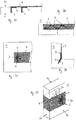
- FIG. 3H and 3I is a possible application of the in the Figures 3F and 3G shown arrangement.
- this is a concrete slab 10, which has a plurality of reinforcing ribs 11, ie T-shaped sections.
- the reinforcing ribs 11 had in the region of their joints with the concrete slab 10 holes 3, which are designed so that in each case two holes in the extension of their drilling axes are interconnected.
- a plurality of grooves extend along the surface of the concrete slab. Similar to the embodiments described above, boreholes and grooves are filled with fiber bundles or fiber strands of the fiber bundle and adhesive.
- a surface reinforcement in the form of a fabric 7 is attached. This fabric is glued in particular all over the surface with the underlying surface.
- FIGS. 4A (Cross-section) and 4B (top view) a further embodiment of the invention, in which arrangements, as for example in the FIGS. 2A and 2B are shown are attached to a support structure 1 at regular intervals.
- the arrangements can be mounted on a surface of the surface of the support structure or on multiple surfaces.
- a fabric 7 is glued to the surface of the support structure, at least with the arrangements, but in particular over its full area.
- the fabric can run continuously over corners and edges in the surface of the support structure.
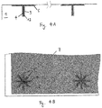
- FIG. 5A shows a section through a non-inventive embodiment of a support structure 1 having a surface consisting of a plurality of surfaces 2a, 2b, 2c, etc. and a first bore 3a, which extends from the surface 2a in the inner region of the support structure.
- the second bore 3b extends from the surface 2b in the inner region of the support structure.
- the surface 2b faces away from the surface 2a.
- a groove 5 extends along the surface of the support structure towards the entry point of the other bore in the support structure. The groove, which thus connects the two inlet holes of the holes with each other, runs in particular on the shortest path between the two holes.
- the groove assumes a different course between the bores, for example to ensure the most uniform possible distribution of force.
- a fiber bundle 4 which opens with its loose ends in the two holes 3a and 3b. Both in the holes and in the groove is adhesive 12 for fixing the fiber bundle.
- FIG. 5B A similar embodiment not according to the invention as in FIG. 5A is also in FIG. 5B represented here, wherein here the fiber bundle surrounds a reinforcing rib 11 of a structure 1.
- FIG. 6A shows a section through a further non-inventive embodiment of the invention, which is a modification of the embodiment FIG. 5A equivalent.
- the embodiment in FIG. 6A two holes 3a, 3b in different, mutually remote surfaces 2a, 2b of the surface of the support structure, wherein the two holes 3a and 3b are arranged so that they are connected to each other in the extension of their respective drilling axes.
- the entry holes of the two Boreholes 3a and 3b are as in FIG. 5A connected to each other via a groove 5.
- Both the holes 3a, 3b and the groove 5 contain an adhesive 12 and a fiber bundle 4.
- the fiber bundle is in particular arranged so that its two ends overlap. This overlap may be in the hole or anywhere in the groove.
- the length of the overlapping region of the fiber bundle is in particular chosen so that a possible seamless power transmission is ensured and is about 5 to 50 cm.
- the preferred embodiments allow a higher efficiency of reinforcement and a much better utilization of the fiber bundle.
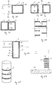
- FIG. 6C shows modifications of the embodiment not according to the invention, as in FIG. 6A is described. Shown here are arrangements according to the invention, as they can be used for example to reinforce a rectangular column as part of a support structure.
- FIG. 6C shows that it is also possible that the fiber bundle 4 is repeatedly passed through a bore, but to run in two different grooves from the entry of the first bore to that of the second bore.
- the embodiment can FIG. 6C also be created by the projecting beyond the bore part of the fiber bundle is divided into two fiber strands, which then extend in different grooves.
- FIG. 6D shows a non-inventive modification of the embodiment, as shown in FIG. 5B is shown, in which case the fiber bundle 4 completely surrounds the reinforcing rib 11.
- FIG. 6E shows a non-inventive side view of a support structure, which in the Figures 6A, 6B and 6C illustrated variants of the arrangement comprises. Depending on the requirements, the different variants can be combined with each other, or several identical arrangements are continuously attached to a support structure.
- FIG. 6G shows a non-inventive support structure 1 comprising a bottom plate 10 and a wall created thereon, the wall is provided in its lower portion with a plurality of arrangements, which from those FIG. 6A correspond.
- a fabric for additional reinforcement of the support structure can be attached via these arrangements (not shown here).
- FIG. 6F shows a cylindrical column comprising a plurality of arrangements.
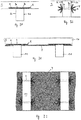
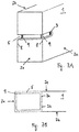
- FIG. 7A shows a detailed view of a section of a non-inventive support structure 1 having a surface consisting of a plurality of surfaces 2a, 2b, 2c, wherein from a surface 2a of a bore 3 extends into an inner region of the support structure.
- the support structure 1 is provided on the surface 2a, from which the bore extends into an inner region of the support structure, with a groove 5 which extends from the bore in a direction on the surface.
- the groove 5 extends over each edge 8, which connects the two surfaces 2 a and 2 c, and 2 c and 2 b of the surface of the structure together, and this one edge 8 has in the interior of the groove 5 a rounding 9.
- FIG. 7B shows a section through a portion of a non-inventive support structure 1, which has two holes 3a, 3c in different, mutually remote surfaces 2a, 2c of the surface of the support structure, wherein the two holes 3a and 3c are arranged so that they in the extension their respective drilling axes are interconnected.
- the inlet holes of the two holes 3a and 3b are connected to each other via a groove 5.
- the edges 8 each have a rounding 9. Again, the respective transitions from the bore into the groove may have a rounding according to the above description.
- Concrete cubes with an edge length of 20 cm were produced as test specimens, using concrete from the same batch for all cubes.
- the concrete cubes were stored for 28 days at 23 ° C and 50% relative humidity.
- the concrete cubes were sanded off on one side to remove cement slurry.
- a hole with a diameter of 20 mm and a depth of 100 mm was attached.
- Two concrete cubes were left without drilling. Starting from the hole, eight grooves with an angle grinder were placed on the concrete cubes evenly around the hole. The grooves were 5 mm wide and 5 mm deep and extended over a length of 8 cm. The angle between the grooves was 45 ° each. With four concrete cubes, only five grooves each were mounted semicircularly.
- Sikadur®-330 commercially available from Sika Nurse AG, with a mean layer thickness of about 1 mm was applied to the machined surface of the concrete cubes without drilling.
- the hole was filled from bottom to top and the grooves filled with Sikadur®-330. It was ensured that no air was trapped in the hole.
- a fiber bundle with a length of 20 cm and a fiber cross-sectional area of about 25 mm 2 was completely impregnated using a brush with Sikadur® 300 from Sika für AG. Subsequently, a cable tie was attached to a loose end of the impregnated fiber bundle and tightened and cut to length. With the help of a knitting needle, which was hooked to the cable tie, the fiber bundle was inserted all the way into the hole. The protruding end of the fiber bundle was divided into fiber strands, the number of fiber strands having to correspond to those of the previously mounted grooves, and inserted into the grooves. In the concrete cubes without grooves, the protruding end of the fiber bundle was fanned out evenly and spread on the machined surface of the concrete cube.
- a fabric provided with SikaWrap® 300 C NW was laminated in the area of the last 20 cm of its loose ends by means of a paint roller with Sikadur®-300.
- a laminated loose end was placed on the machined surface of the concrete cube and pressed there with a paint roller.
- Sikadur®-330 was applied over the attached tissue using a dental trowel.
- the fabric was looped over and the other loose and laminated end was placed on the same spot of the concrete cube so that the two ends of the fabric came to lie one above the other. Again, the fabric was pressed with the paint roller. With a spatula of the width of the concrete cube, excess adhesive was removed from the specimen.
- test specimens thus produced were left for 7 days at 23 ° C and 50% relative humidity, so that the adhesive could cure.
- specimens were also made with fiber bundles of glass fibers with a fiber cross-sectional area of about 25 mm 2 .
- the tensile shear strength of different test specimens was measured according to ISO 527-4 / EN 2561 with a measuring speed of 2 mm / min at 23 ° C and a relative humidity of 50%.
- the tensile shear strength of the bond was tested by placing the loop formed by the SikaWrap-300C NW fabric around a steel pipe connected to the moving frame of the testing machine.
Landscapes
- Engineering & Computer Science (AREA)
- Architecture (AREA)
- Civil Engineering (AREA)
- Structural Engineering (AREA)
- Chemical & Material Sciences (AREA)
- Chemical Kinetics & Catalysis (AREA)
- Electrochemistry (AREA)
- Mechanical Engineering (AREA)
- Reinforcement Elements For Buildings (AREA)
- Working Measures On Existing Buildindgs (AREA)
- Bridges Or Land Bridges (AREA)
- Foundations (AREA)
Priority Applications (2)
| Application Number | Priority Date | Filing Date | Title |
|---|---|---|---|
| EP17163975.0A EP3216944B1 (de) | 2013-06-06 | 2014-06-06 | Anordnung zur verstärkung von tragstrukturen |
| EP14728978.9A EP3004490B1 (de) | 2013-06-06 | 2014-06-06 | Anordnung und verfahren zur verstärkung von tragstrukturen |
Applications Claiming Priority (3)
| Application Number | Priority Date | Filing Date | Title |
|---|---|---|---|
| EP13170879 | 2013-06-06 | ||
| EP14728978.9A EP3004490B1 (de) | 2013-06-06 | 2014-06-06 | Anordnung und verfahren zur verstärkung von tragstrukturen |
| PCT/EP2014/061915 WO2014195504A1 (de) | 2013-06-06 | 2014-06-06 | Anordnung und verfahren zur verstärkung von tragstrukturen |
Related Child Applications (2)
| Application Number | Title | Priority Date | Filing Date |
|---|---|---|---|
| EP17163975.0A Division EP3216944B1 (de) | 2013-06-06 | 2014-06-06 | Anordnung zur verstärkung von tragstrukturen |
| EP17163975.0A Division-Into EP3216944B1 (de) | 2013-06-06 | 2014-06-06 | Anordnung zur verstärkung von tragstrukturen |
Publications (2)
| Publication Number | Publication Date |
|---|---|
| EP3004490A1 EP3004490A1 (de) | 2016-04-13 |
| EP3004490B1 true EP3004490B1 (de) | 2017-08-09 |
Family
ID=48577565
Family Applications (2)
| Application Number | Title | Priority Date | Filing Date |
|---|---|---|---|
| EP14728978.9A Active EP3004490B1 (de) | 2013-06-06 | 2014-06-06 | Anordnung und verfahren zur verstärkung von tragstrukturen |
| EP17163975.0A Active EP3216944B1 (de) | 2013-06-06 | 2014-06-06 | Anordnung zur verstärkung von tragstrukturen |
Family Applications After (1)
| Application Number | Title | Priority Date | Filing Date |
|---|---|---|---|
| EP17163975.0A Active EP3216944B1 (de) | 2013-06-06 | 2014-06-06 | Anordnung zur verstärkung von tragstrukturen |
Country Status (9)
| Country | Link |
|---|---|
| US (1) | US9574359B2 (enExample) |
| EP (2) | EP3004490B1 (enExample) |
| JP (1) | JP6437534B2 (enExample) |
| CN (2) | CN107663953B (enExample) |
| AU (2) | AU2014276778B2 (enExample) |
| BR (1) | BR112015030524A2 (enExample) |
| CA (1) | CA2914506C (enExample) |
| ES (2) | ES2646943T3 (enExample) |
| WO (1) | WO2014195504A1 (enExample) |
Families Citing this family (10)
| Publication number | Priority date | Publication date | Assignee | Title |
|---|---|---|---|---|
| US9976315B2 (en) | 2013-08-08 | 2018-05-22 | University Of Utah Research Foundation | Elongate member reinforcement |
| US10227786B2 (en) * | 2013-08-08 | 2019-03-12 | University Of Utah Research Foundation | Elongate member reinforcement with a studded collar |
| ITVI20150072A1 (it) | 2015-03-16 | 2016-09-16 | Carbonveneta Tecnologia Nei Compositi S R L | Procedimento per la realizzazione di un connettore del tipo cosiddetto a "fiocco" |
| EP3211156A1 (en) | 2016-02-29 | 2017-08-30 | VSL International AG | Method and arrangement for strengthening a concrete structure, and reinforced concrete structure |
| CH712326B1 (fr) * | 2016-05-04 | 2020-10-30 | S&P Clever Reinforcement Company Ag | Procédé de renforcement de murs, de dalles, de sols et d'autres éléments en béton. |
| CN106168016A (zh) * | 2016-08-30 | 2016-11-30 | 东莞理工学院 | 桥面板加固结构和桥面板加固方法 |
| MX2020006570A (es) * | 2017-12-21 | 2020-09-09 | Soletanche Freyssinet | Metodo para reforzar una estructura de ingenieria civil. |
| US11236508B2 (en) * | 2018-12-12 | 2022-02-01 | Structural Technologies Ip, Llc | Fiber reinforced composite cord for repair of concrete end members |
| AU2021203313B2 (en) * | 2021-04-16 | 2024-06-06 | Ina Acquisition Corp. | Method of reinforcement of masonry walls with non-visible high strength preformed fibrous laminates |
| JP2023030676A (ja) * | 2021-08-23 | 2023-03-08 | コニシ株式会社 | 構造物の補強方法及び補強構造 |
Family Cites Families (26)
| Publication number | Priority date | Publication date | Assignee | Title |
|---|---|---|---|---|
| US5649398A (en) * | 1994-06-10 | 1997-07-22 | Hexcel-Fyfe L.L.C. | High strength fabric reinforced walls |
| JPH10512635A (ja) * | 1995-01-09 | 1998-12-02 | アイトゲヌーシシエ マテリアルプルーフングス−ウント フォルシュングスアンスタルト エ−エムペーアー | 補強平板の固定方法 |
| JPH08209893A (ja) * | 1995-02-06 | 1996-08-13 | Kawabata Seiji | 端部埋め込み枠強化工法 |
| WO1998032933A1 (de) * | 1997-01-23 | 1998-07-30 | Sika Ag, Vormals Kaspar Winkler & Co. | Flachband-lamelle zur verstärkung von bauteilen sowie verfahren zu deren herstellung |
| DE19733067A1 (de) * | 1997-07-31 | 1999-02-04 | Sika Ag | Flachband-Lamelle zur Verstärkung von Bauteilen sowie Verfahren zur Anbringung der Flachband-Lamelle an einem Bauteil |
| ES2165693T3 (es) * | 1997-08-26 | 2002-03-16 | Stresshead Ag | Dispositivo de refuerzo para estructuras portantes. |
| JP3983902B2 (ja) * | 1998-09-18 | 2007-09-26 | 鹿島建設株式会社 | 柱の耐震補強方法 |
| JP3532441B2 (ja) * | 1999-03-17 | 2004-05-31 | 蓮太郎 難波 | 構造材同士の接合箇所における補強構造及び補強方法 |
| AU2001227722A1 (en) * | 2000-01-13 | 2001-07-24 | Dow Global Technologies Inc. | Composites of reinforcing fibers and thermoplastic resins as external structuralsupports |
| US20050076596A1 (en) * | 2001-09-25 | 2005-04-14 | Structural Quality Assurance, Inc. | Reinforcement material and reinforcement structure of structure and method of designing reinforcement material |
| JP3892767B2 (ja) * | 2002-06-27 | 2007-03-14 | 清水建設株式会社 | 定着用アンカー、定着用アンカーの製造方法、及びコンクリート構造物の補修補強方法 |
| US7574840B1 (en) | 2002-07-24 | 2009-08-18 | Fyfe Co., Llc | Connector for reinforcing the attachment among structural components |
| US7207149B2 (en) * | 2002-07-24 | 2007-04-24 | Fyfe Edward R | Anchor and method for reinforcing a structure |
| JP2004316137A (ja) * | 2003-04-14 | 2004-11-11 | Toray Ind Inc | 補強構造物 |
| US7823354B2 (en) * | 2004-04-26 | 2010-11-02 | Wheatley Donald E | Structure reinforcement system |
| US7743585B2 (en) * | 2004-04-26 | 2010-06-29 | Donald E Wheatley | Structure reinforcement system |
| ITRM20050066A1 (it) * | 2005-02-17 | 2006-08-18 | Tec Inn S R L | Metodo per rinforzare strutture edili e rivestimento ottenuto da tale metodo. |
| ITPG20050028A1 (it) * | 2005-05-23 | 2005-08-22 | Kimia S P A | Elementi strutturali per il rinforzo di componenti edilizi |
| JP2007198071A (ja) * | 2006-01-30 | 2007-08-09 | Toray Ind Inc | コンクリートスラブ開口部の補強構造とその補強方法 |
| FR2918689B1 (fr) * | 2007-07-09 | 2012-06-01 | Freyssinet | Procede de renforcement d'un ouvrage de construction, et ouvrage ainsi renforce. |
| US7946088B1 (en) * | 2009-01-22 | 2011-05-24 | Fyfe Edward R | System for reinforcing structure using site-customized materials |
| FR2948712B1 (fr) * | 2009-08-03 | 2015-03-06 | Soletanche Freyssinet | Procede de renforcement d'une structure de construction, et ouvrage ainsi renforce |
| US9194140B2 (en) * | 2010-11-04 | 2015-11-24 | Garland Industries, Inc. | Method and apparatus for repairing concrete |
| CN102199951A (zh) * | 2011-01-31 | 2011-09-28 | 云南巨和建设集团有限公司 | 使用碳纤维加固混凝土结构的施工方法 |
| JP3177016U (ja) * | 2012-05-02 | 2012-07-12 | 株式会社ニシケン | コンクリートの断面修復用補強金具 |
| US20140205800A1 (en) * | 2013-01-23 | 2014-07-24 | Milliken & Company | Externally bonded fiber reinforced polymer strengthening system |
-
2014
- 2014-06-06 ES ES14728978.9T patent/ES2646943T3/es active Active
- 2014-06-06 CN CN201710814590.5A patent/CN107663953B/zh active Active
- 2014-06-06 WO PCT/EP2014/061915 patent/WO2014195504A1/de not_active Ceased
- 2014-06-06 AU AU2014276778A patent/AU2014276778B2/en active Active
- 2014-06-06 EP EP14728978.9A patent/EP3004490B1/de active Active
- 2014-06-06 US US14/896,284 patent/US9574359B2/en active Active
- 2014-06-06 CN CN201480042835.1A patent/CN105431601B/zh active Active
- 2014-06-06 EP EP17163975.0A patent/EP3216944B1/de active Active
- 2014-06-06 CA CA2914506A patent/CA2914506C/en active Active
- 2014-06-06 BR BR112015030524A patent/BR112015030524A2/pt active Search and Examination
- 2014-06-06 JP JP2016517629A patent/JP6437534B2/ja active Active
- 2014-06-06 ES ES17163975T patent/ES2900021T3/es active Active
-
2017
- 2017-12-15 AU AU2017276343A patent/AU2017276343B2/en active Active
Non-Patent Citations (1)
| Title |
|---|
| None * |
Also Published As
| Publication number | Publication date |
|---|---|
| CN107663953A (zh) | 2018-02-06 |
| JP6437534B2 (ja) | 2018-12-12 |
| AU2017276343B2 (en) | 2019-08-15 |
| CN107663953B (zh) | 2020-03-10 |
| BR112015030524A2 (pt) | 2017-07-25 |
| US9574359B2 (en) | 2017-02-21 |
| AU2014276778A1 (en) | 2016-01-21 |
| WO2014195504A1 (de) | 2014-12-11 |
| JP2016524669A (ja) | 2016-08-18 |
| EP3216944A1 (de) | 2017-09-13 |
| CN105431601A (zh) | 2016-03-23 |
| EP3216944B1 (de) | 2021-09-29 |
| ES2900021T3 (es) | 2022-03-15 |
| CA2914506C (en) | 2022-09-06 |
| CN105431601B (zh) | 2017-09-29 |
| CA2914506A1 (en) | 2014-12-11 |
| EP3004490A1 (de) | 2016-04-13 |
| US20160138285A1 (en) | 2016-05-19 |
| AU2014276778B2 (en) | 2017-10-12 |
| ES2646943T3 (es) | 2017-12-18 |
| AU2017276343A1 (en) | 2018-01-18 |
Similar Documents
| Publication | Publication Date | Title |
|---|---|---|
| EP3004490B1 (de) | Anordnung und verfahren zur verstärkung von tragstrukturen | |
| WO1996021785A1 (de) | Befestigung von verstärkungslamellen | |
| EP2817465B1 (de) | Vorrichtung zur krafteinleitung in zugglieder aus faserverstärkten kunststoff-flachbandlamellen | |
| DE4029134A1 (de) | Verbundkonstruktion | |
| EP2722466B1 (de) | Verbundsystem zur Verstärkung von Bauteilen | |
| DE2945752C2 (enExample) | ||
| EP2606185B1 (de) | Vorrichtung zur krafteinleitung in zugglieder aus faserverstärkten kunststoff-flachbandlamellen | |
| EP1088945B1 (de) | Fassadendämmelement | |
| EP0732464B1 (de) | Verfahren zur Herstellung von armierten Beschichtungen, insbesondere auf Betonoberflächen, und zugehöriges Armierungsnetz | |
| DE19828607A1 (de) | Verfahren zum Verstärken von Stahl- und Spannbetonbauteilen | |
| CH671057A5 (enExample) | ||
| DE19716472C2 (de) | Bauelement, daraus hergestellte Schwergewichtsmauer und Verfahren zur Herstellung der Schwergewichtsmauer | |
| WO2012163856A1 (de) | Verbindungsanordnung und verfahren zur herstellung einer durchstanzsicherung einer nachträglichen querkraftverstärkung bzw. eines bewehrungsanschlusses | |
| DE102008009057A1 (de) | Holzmastegründung | |
| DE202012101506U1 (de) | Anker für Wände, zum Befestigen von abragenden Bauwerken wie Markisen | |
| DE102012103546A1 (de) | Anker für Wände, zum Befestigen von abragenden Bauwerken wie Markisen | |
| DE69123517T2 (de) | Verfahren zur Herstellung einer Stahlblechbetondecke | |
| DE19730174A1 (de) | Bauteil | |
| DE2705483C2 (enExample) | ||
| DE102007004573A1 (de) | Wandbauelement, Verfahren zur Herstellung eines Wandbauelements und ein Ankerbauteil für ein Wandbauelement | |
| AT380502B (de) | Verfahren und vorrichtung zum verbreitern von fahrbahnplatten, brueckenfahrbahnen od.dgl. | |
| EP4124703A1 (de) | Verstärkte stahlbetonkonstruktion | |
| DE3039080C2 (de) | Ausbaubares, mehrteiliges Zugglied für einen Verpreßanker | |
| DE19539234A1 (de) | Wandelement | |
| DE69602266T2 (de) | Bauelement für brücken und boden |
Legal Events
| Date | Code | Title | Description |
|---|---|---|---|
| PUAI | Public reference made under article 153(3) epc to a published international application that has entered the european phase |
Free format text: ORIGINAL CODE: 0009012 |
|
| 17P | Request for examination filed |
Effective date: 20160107 |
|
| AK | Designated contracting states |
Kind code of ref document: A1 Designated state(s): AL AT BE BG CH CY CZ DE DK EE ES FI FR GB GR HR HU IE IS IT LI LT LU LV MC MK MT NL NO PL PT RO RS SE SI SK SM TR |
|
| AX | Request for extension of the european patent |
Extension state: BA ME |
|
| DAX | Request for extension of the european patent (deleted) | ||
| REG | Reference to a national code |
Ref country code: DE Ref legal event code: R079 Ref document number: 502014004937 Country of ref document: DE Free format text: PREVIOUS MAIN CLASS: E04G0023020000 Ipc: E04C0005070000 |
|
| RIC1 | Information provided on ipc code assigned before grant |
Ipc: E04C 5/07 20060101AFI20161223BHEP Ipc: E04G 23/02 20060101ALI20161223BHEP |
|
| GRAP | Despatch of communication of intention to grant a patent |
Free format text: ORIGINAL CODE: EPIDOSNIGR1 |
|
| STAA | Information on the status of an ep patent application or granted ep patent |
Free format text: STATUS: GRANT OF PATENT IS INTENDED |
|
| INTG | Intention to grant announced |
Effective date: 20170223 |
|
| GRAS | Grant fee paid |
Free format text: ORIGINAL CODE: EPIDOSNIGR3 |
|
| GRAA | (expected) grant |
Free format text: ORIGINAL CODE: 0009210 |
|
| STAA | Information on the status of an ep patent application or granted ep patent |
Free format text: STATUS: THE PATENT HAS BEEN GRANTED |
|
| AK | Designated contracting states |
Kind code of ref document: B1 Designated state(s): AL AT BE BG CH CY CZ DE DK EE ES FI FR GB GR HR HU IE IS IT LI LT LU LV MC MK MT NL NO PL PT RO RS SE SI SK SM TR |
|
| REG | Reference to a national code |
Ref country code: GB Ref legal event code: FG4D Free format text: NOT ENGLISH |
|
| REG | Reference to a national code |
Ref country code: CH Ref legal event code: EP Ref country code: AT Ref legal event code: REF Ref document number: 917011 Country of ref document: AT Kind code of ref document: T Effective date: 20170815 |
|
| REG | Reference to a national code |
Ref country code: IE Ref legal event code: FG4D Free format text: LANGUAGE OF EP DOCUMENT: GERMAN |
|
| REG | Reference to a national code |
Ref country code: DE Ref legal event code: R096 Ref document number: 502014004937 Country of ref document: DE |
|
| REG | Reference to a national code |
Ref country code: NL Ref legal event code: MP Effective date: 20170809 |
|
| REG | Reference to a national code |
Ref country code: ES Ref legal event code: FG2A Ref document number: 2646943 Country of ref document: ES Kind code of ref document: T3 Effective date: 20171218 |
|
| REG | Reference to a national code |
Ref country code: LT Ref legal event code: MG4D |
|
| PG25 | Lapsed in a contracting state [announced via postgrant information from national office to epo] |
Ref country code: LT Free format text: LAPSE BECAUSE OF FAILURE TO SUBMIT A TRANSLATION OF THE DESCRIPTION OR TO PAY THE FEE WITHIN THE PRESCRIBED TIME-LIMIT Effective date: 20170809 Ref country code: SE Free format text: LAPSE BECAUSE OF FAILURE TO SUBMIT A TRANSLATION OF THE DESCRIPTION OR TO PAY THE FEE WITHIN THE PRESCRIBED TIME-LIMIT Effective date: 20170809 Ref country code: NO Free format text: LAPSE BECAUSE OF FAILURE TO SUBMIT A TRANSLATION OF THE DESCRIPTION OR TO PAY THE FEE WITHIN THE PRESCRIBED TIME-LIMIT Effective date: 20171109 Ref country code: NL Free format text: LAPSE BECAUSE OF FAILURE TO SUBMIT A TRANSLATION OF THE DESCRIPTION OR TO PAY THE FEE WITHIN THE PRESCRIBED TIME-LIMIT Effective date: 20170809 Ref country code: FI Free format text: LAPSE BECAUSE OF FAILURE TO SUBMIT A TRANSLATION OF THE DESCRIPTION OR TO PAY THE FEE WITHIN THE PRESCRIBED TIME-LIMIT Effective date: 20170809 Ref country code: HR Free format text: LAPSE BECAUSE OF FAILURE TO SUBMIT A TRANSLATION OF THE DESCRIPTION OR TO PAY THE FEE WITHIN THE PRESCRIBED TIME-LIMIT Effective date: 20170809 |
|
| PG25 | Lapsed in a contracting state [announced via postgrant information from national office to epo] |
Ref country code: RS Free format text: LAPSE BECAUSE OF FAILURE TO SUBMIT A TRANSLATION OF THE DESCRIPTION OR TO PAY THE FEE WITHIN THE PRESCRIBED TIME-LIMIT Effective date: 20170809 Ref country code: IS Free format text: LAPSE BECAUSE OF FAILURE TO SUBMIT A TRANSLATION OF THE DESCRIPTION OR TO PAY THE FEE WITHIN THE PRESCRIBED TIME-LIMIT Effective date: 20171209 Ref country code: BG Free format text: LAPSE BECAUSE OF FAILURE TO SUBMIT A TRANSLATION OF THE DESCRIPTION OR TO PAY THE FEE WITHIN THE PRESCRIBED TIME-LIMIT Effective date: 20171109 Ref country code: PL Free format text: LAPSE BECAUSE OF FAILURE TO SUBMIT A TRANSLATION OF THE DESCRIPTION OR TO PAY THE FEE WITHIN THE PRESCRIBED TIME-LIMIT Effective date: 20170809 Ref country code: LV Free format text: LAPSE BECAUSE OF FAILURE TO SUBMIT A TRANSLATION OF THE DESCRIPTION OR TO PAY THE FEE WITHIN THE PRESCRIBED TIME-LIMIT Effective date: 20170809 |
|
| PG25 | Lapsed in a contracting state [announced via postgrant information from national office to epo] |
Ref country code: CZ Free format text: LAPSE BECAUSE OF FAILURE TO SUBMIT A TRANSLATION OF THE DESCRIPTION OR TO PAY THE FEE WITHIN THE PRESCRIBED TIME-LIMIT Effective date: 20170809 Ref country code: RO Free format text: LAPSE BECAUSE OF FAILURE TO SUBMIT A TRANSLATION OF THE DESCRIPTION OR TO PAY THE FEE WITHIN THE PRESCRIBED TIME-LIMIT Effective date: 20170809 Ref country code: DK Free format text: LAPSE BECAUSE OF FAILURE TO SUBMIT A TRANSLATION OF THE DESCRIPTION OR TO PAY THE FEE WITHIN THE PRESCRIBED TIME-LIMIT Effective date: 20170809 |
|
| REG | Reference to a national code |
Ref country code: FR Ref legal event code: PLFP Year of fee payment: 5 |
|
| REG | Reference to a national code |
Ref country code: GR Ref legal event code: EP Ref document number: 20170403070 Country of ref document: GR Effective date: 20180420 |
|
| REG | Reference to a national code |
Ref country code: DE Ref legal event code: R097 Ref document number: 502014004937 Country of ref document: DE |
|
| PG25 | Lapsed in a contracting state [announced via postgrant information from national office to epo] |
Ref country code: SK Free format text: LAPSE BECAUSE OF FAILURE TO SUBMIT A TRANSLATION OF THE DESCRIPTION OR TO PAY THE FEE WITHIN THE PRESCRIBED TIME-LIMIT Effective date: 20170809 Ref country code: EE Free format text: LAPSE BECAUSE OF FAILURE TO SUBMIT A TRANSLATION OF THE DESCRIPTION OR TO PAY THE FEE WITHIN THE PRESCRIBED TIME-LIMIT Effective date: 20170809 Ref country code: SM Free format text: LAPSE BECAUSE OF FAILURE TO SUBMIT A TRANSLATION OF THE DESCRIPTION OR TO PAY THE FEE WITHIN THE PRESCRIBED TIME-LIMIT Effective date: 20170809 |
|
| PLBE | No opposition filed within time limit |
Free format text: ORIGINAL CODE: 0009261 |
|
| STAA | Information on the status of an ep patent application or granted ep patent |
Free format text: STATUS: NO OPPOSITION FILED WITHIN TIME LIMIT |
|
| 26N | No opposition filed |
Effective date: 20180511 |
|
| PG25 | Lapsed in a contracting state [announced via postgrant information from national office to epo] |
Ref country code: SI Free format text: LAPSE BECAUSE OF FAILURE TO SUBMIT A TRANSLATION OF THE DESCRIPTION OR TO PAY THE FEE WITHIN THE PRESCRIBED TIME-LIMIT Effective date: 20170809 |
|
| PG25 | Lapsed in a contracting state [announced via postgrant information from national office to epo] |
Ref country code: MT Free format text: LAPSE BECAUSE OF FAILURE TO SUBMIT A TRANSLATION OF THE DESCRIPTION OR TO PAY THE FEE WITHIN THE PRESCRIBED TIME-LIMIT Effective date: 20170809 |
|
| REG | Reference to a national code |
Ref country code: DE Ref legal event code: R119 Ref document number: 502014004937 Country of ref document: DE |
|
| REG | Reference to a national code |
Ref country code: BE Ref legal event code: MM Effective date: 20180630 |
|
| REG | Reference to a national code |
Ref country code: IE Ref legal event code: MM4A |
|
| PG25 | Lapsed in a contracting state [announced via postgrant information from national office to epo] |
Ref country code: MC Free format text: LAPSE BECAUSE OF FAILURE TO SUBMIT A TRANSLATION OF THE DESCRIPTION OR TO PAY THE FEE WITHIN THE PRESCRIBED TIME-LIMIT Effective date: 20170809 Ref country code: LU Free format text: LAPSE BECAUSE OF NON-PAYMENT OF DUE FEES Effective date: 20180606 |
|
| PG25 | Lapsed in a contracting state [announced via postgrant information from national office to epo] |
Ref country code: IE Free format text: LAPSE BECAUSE OF NON-PAYMENT OF DUE FEES Effective date: 20180606 Ref country code: DE Free format text: LAPSE BECAUSE OF NON-PAYMENT OF DUE FEES Effective date: 20190101 |
|
| PG25 | Lapsed in a contracting state [announced via postgrant information from national office to epo] |
Ref country code: BE Free format text: LAPSE BECAUSE OF NON-PAYMENT OF DUE FEES Effective date: 20180630 |
|
| PG25 | Lapsed in a contracting state [announced via postgrant information from national office to epo] |
Ref country code: PT Free format text: LAPSE BECAUSE OF FAILURE TO SUBMIT A TRANSLATION OF THE DESCRIPTION OR TO PAY THE FEE WITHIN THE PRESCRIBED TIME-LIMIT Effective date: 20170809 |
|
| PG25 | Lapsed in a contracting state [announced via postgrant information from national office to epo] |
Ref country code: CY Free format text: LAPSE BECAUSE OF FAILURE TO SUBMIT A TRANSLATION OF THE DESCRIPTION OR TO PAY THE FEE WITHIN THE PRESCRIBED TIME-LIMIT Effective date: 20170809 Ref country code: MK Free format text: LAPSE BECAUSE OF NON-PAYMENT OF DUE FEES Effective date: 20170809 Ref country code: HU Free format text: LAPSE BECAUSE OF FAILURE TO SUBMIT A TRANSLATION OF THE DESCRIPTION OR TO PAY THE FEE WITHIN THE PRESCRIBED TIME-LIMIT; INVALID AB INITIO Effective date: 20140606 |
|
| PG25 | Lapsed in a contracting state [announced via postgrant information from national office to epo] |
Ref country code: AL Free format text: LAPSE BECAUSE OF FAILURE TO SUBMIT A TRANSLATION OF THE DESCRIPTION OR TO PAY THE FEE WITHIN THE PRESCRIBED TIME-LIMIT Effective date: 20170809 |
|
| REG | Reference to a national code |
Ref country code: AT Ref legal event code: MM01 Ref document number: 917011 Country of ref document: AT Kind code of ref document: T Effective date: 20190606 |
|
| PG25 | Lapsed in a contracting state [announced via postgrant information from national office to epo] |
Ref country code: AT Free format text: LAPSE BECAUSE OF NON-PAYMENT OF DUE FEES Effective date: 20190606 |
|
| PGFP | Annual fee paid to national office [announced via postgrant information from national office to epo] |
Ref country code: GB Payment date: 20250520 Year of fee payment: 12 |
|
| PGFP | Annual fee paid to national office [announced via postgrant information from national office to epo] |
Ref country code: IT Payment date: 20250520 Year of fee payment: 12 |
|
| PGFP | Annual fee paid to national office [announced via postgrant information from national office to epo] |
Ref country code: FR Payment date: 20250520 Year of fee payment: 12 |
|
| PGFP | Annual fee paid to national office [announced via postgrant information from national office to epo] |
Ref country code: GR Payment date: 20250522 Year of fee payment: 12 |
|
| PGFP | Annual fee paid to national office [announced via postgrant information from national office to epo] |
Ref country code: TR Payment date: 20250527 Year of fee payment: 12 |
|
| PGFP | Annual fee paid to national office [announced via postgrant information from national office to epo] |
Ref country code: ES Payment date: 20250701 Year of fee payment: 12 |
|
| PGFP | Annual fee paid to national office [announced via postgrant information from national office to epo] |
Ref country code: CH Payment date: 20250707 Year of fee payment: 12 |