EP3004490B1 - Assembly and method for reinforcing support structures - Google Patents
Assembly and method for reinforcing support structures Download PDFInfo
- Publication number
- EP3004490B1 EP3004490B1 EP14728978.9A EP14728978A EP3004490B1 EP 3004490 B1 EP3004490 B1 EP 3004490B1 EP 14728978 A EP14728978 A EP 14728978A EP 3004490 B1 EP3004490 B1 EP 3004490B1
- Authority
- EP
- European Patent Office
- Prior art keywords
- bore
- fiber bundle
- grooves
- supporting structure
- support structure
- Prior art date
- Legal status (The legal status is an assumption and is not a legal conclusion. Google has not performed a legal analysis and makes no representation as to the accuracy of the status listed.)
- Active
Links
Images


Classifications
-
- E—FIXED CONSTRUCTIONS
- E04—BUILDING
- E04G—SCAFFOLDING; FORMS; SHUTTERING; BUILDING IMPLEMENTS OR AIDS, OR THEIR USE; HANDLING BUILDING MATERIALS ON THE SITE; REPAIRING, BREAKING-UP OR OTHER WORK ON EXISTING BUILDINGS
- E04G23/00—Working measures on existing buildings
- E04G23/02—Repairing, e.g. filling cracks; Restoring; Altering; Enlarging
- E04G23/0218—Increasing or restoring the load-bearing capacity of building construction elements
-
- E—FIXED CONSTRUCTIONS
- E04—BUILDING
- E04C—STRUCTURAL ELEMENTS; BUILDING MATERIALS
- E04C5/00—Reinforcing elements, e.g. for concrete; Auxiliary elements therefor
- E04C5/07—Reinforcing elements of material other than metal, e.g. of glass, of plastics, or not exclusively made of metal
-
- E—FIXED CONSTRUCTIONS
- E04—BUILDING
- E04G—SCAFFOLDING; FORMS; SHUTTERING; BUILDING IMPLEMENTS OR AIDS, OR THEIR USE; HANDLING BUILDING MATERIALS ON THE SITE; REPAIRING, BREAKING-UP OR OTHER WORK ON EXISTING BUILDINGS
- E04G23/00—Working measures on existing buildings
- E04G23/02—Repairing, e.g. filling cracks; Restoring; Altering; Enlarging
- E04G23/0218—Increasing or restoring the load-bearing capacity of building construction elements
- E04G2023/0251—Increasing or restoring the load-bearing capacity of building construction elements by using fiber reinforced plastic elements
- E04G2023/0262—Devices specifically adapted for anchoring the fiber reinforced plastic elements, e.g. to avoid peeling off
Definitions
- the invention relates to the field of reinforcement of support structures, preferably by applying surface reinforcement, in particular the introduction of force into the surface reinforcement.
- a widely used method is to introduce fiber bundles into a bore in the support structure and to anchor them there and to spread out or fan out an end of the fiber bundle projecting beyond the surface and to stick it to the surface.
- a surface reinforcement can then be glued to the reinforced structural surface.
- the surface reinforcement may first be glued to the structural surface, so that when an anchor attached thereto from a fiber bundle, the protruding end of this is glued to the surface of the surface reinforcement.
- the near-surface potential fracture surface of each anchor is broken at only one point (at the shank).
- the resistance of this potential fracture surface is thus increased only to a limited extent.
- the transmission of force from the fibers of the fiber bundle spread on the surface to the fibers of the fabric is not optimal.
- the very thin, formed by the fibers of the fiber bundle on the surface fiber composite material can be charged only in the pulling direction substantially.
- the fiber composite material buckles, but when subjected to thrust and bending, only very small forces can be transmitted. Therefore, only the approximately in the pulling direction of the surface reinforcement fibers are fully effective. These make up only a small part of the fiber bundle cross-section and cover only a small part of the width of the surface reinforcement.
- the object of the present invention is therefore to provide an arrangement and a method according to which an improvement in the introduction of force into a surface reinforcement is to be achieved.
- the core of the invention is therefore an assembly comprising a support structure having a surface consisting of one or more surfaces, wherein extending from at least one surface of a bore in an inner region of the support structure, and this bore with an adhesive and with a portion of a via this bore protruding fiber bundle is filled, wherein the support structure is provided on the at least one surface, from which the bore extends in an inner region of the support structure, with a plurality of grooves extending from the bore in a region of at least one circular sector and the protruding part of the fiber bundle divided into fiber strands at least partially located in the grooves and is secured therein with the adhesive.
- a support structure here is an element or part of an element referred to which is exposed to forces.
- the support structure is a building or component of a building, such as a slab, ceiling, wall, pillar, rib, beam or the like.
- the support structure is typically made of concrete, especially reinforced concrete, but may also consist of bricks or other bricks, wood, steel or other materials and any combination of these materials.
- the buildings are civil engineering works, such as houses, bridges, tunnels, dams, sports facilities, etc.
- the fiber bundle is a loose arrangement of substantially rectified individual fibers or filaments, in particular of carbon (carbon), glass, basalt, aramid, steel or other inorganic or organic materials.
- the fibers are carbon fibers.
- the thickness of the fiber bundle depends on the area of use and on the forces which are to be transmitted through the fiber bundle. If the fiber bundle consists of carbon fibers, this comprises, in particular, 1000 to 50,000 individual fibers, each themselves having a diameter in the range from 5 to 10 have ⁇ m.
- a typical fiber bundle preferably has a cross-sectional area of from 20 to 70 mm 2 , in particular from 25 to 40 mm 2 .
- the attachment of the fiber bundle to the support structure is typically carried out by attaching, in a first step, at the desired location, a bore which serves to receive a portion of the fiber bundle.
- the bore can be created by any means, such means are well known to those skilled.
- the dimensions of the bore resulting from the strength and the length of the fiber bundle and this in turn of the requirements that are imposed on the inventive arrangement.
- a suitable bore has a diameter of 1 to 5 cm, in particular 1.5 to 3 cm and a depth of 5 to 30 cm, in particular from 7 to 20 cm.
- one or more grooves are made starting from the bore or from the point of entry of the bore into the surface of the support structure.
- the grooves can be created by any means, for example with an angle grinder.
- the grooves are dimensioned so that they in their entirety, the fiber bundle, which can be divided into individual fiber strands in the event that multiple grooves are present, can accommodate.
- the fiber bundle After attaching the bore and the plurality of grooves, the fiber bundle is inserted into the bore and grooves and glued therein.
- an adhesive is first introduced into the bore and into the grooves.
- the fiber bundle which is preferably pre-impregnated with a resin, introduced into the bore so that a portion of the fiber bundle protrudes beyond the bore.
- the portion of the fiber bundle which is in the assembled arrangement in multiple grooves, then does not protrude more beyond the surface of the support structure, whereby a uniform and smooth surface can be ensured.
- This projecting portion of the fiber bundle is at least partially inserted into the adhesive groove or uniformly divided into a number of grooves corresponding number fiber strands and inserted into the grooves.
- the entire fiber bundle or all fiber strands are inserted into a plurality of grooves, so that the fiber bundle does not protrude beyond the surface of the support structure at any point.
- the fiber bundle can be pressed in it.
- Adhesive material emerging from the wellbore or grooves is then removed or evenly distributed in the area of the surface affected by the assembly. Are there any cavities in the hole or in the grooves after inserting the fiber bundle, these can be filled with adhesive.
- the introduction of the fiber bundle into the bore takes place in particular with a needle-like object.
- a clip, a cable tie or the like can be attached to which the needle-like object can be hooked for better guidance with the needle-like object.
- the impregnation of the fiber bundle with a resin prior to insertion in the bore and grooves has the advantage that the wetting of the entire fiber bundle with resin, even in the inner region, can be achieved.
- the resin for impregnating the fiber bundle in particular has the same chemical basis as the adhesive for fastening the fiber bundle in the bore and grooves.
- both the resin and the adhesive are epoxy resin compositions. It is possible that the adhesive and the resin are the same composition, with the viscosity of the resin typically being set slightly lower than that of the adhesive, which in turn serves to better wet the fibers.
- a two-component epoxy resin composition is preferably used.
- Suitable epoxy resin compositions are, for example, under the trade names Sikadur ® are commercially available from Sika Switzerland AG.
- the bonding sites on the support structure are preferably clean, dry, free of dust and grease. Depending on the materials of which the support structure is made, suitable cleaning measures or pretreatments may be used.
- the inventive arrangement can be attached to a support structure for different purposes.
- the arrangement itself serves as a reinforcement for the support structure and / or serves as an anchor or as an anchorage for a surface reinforcement attached to the support structure.
- the arrangement serves as an anchorage for a surface reinforcement attached to the support structure, then it has several grooves which extend from the bore along the surface.
- the number of grooves per bore is preferably 2 to 16, in particular 6 to 10.
- the grooves are in particular circular and arranged at regular intervals around the bore.
- the grooves are arranged in a circular sector around the bore, wherein the circular sector preferably has a center angle of 60 to 360 °.
- the arrangement of the grooves depends on the loading direction of the surface reinforcement, which is adhesively bonded to the supporting structure via the arrangement according to the invention as an anchor or anchoring.
- the grooves extend in this case in the pulling direction of the surface reinforcement.
- the arrangement itself can serve to reinforce a supporting structure.
- several of the arrangements described are mounted at regular intervals on a support structure.
- the arrangement preferably has a second bore which extends into an inner region of the support structure, wherein the second bore may be located on the same or on another surface of the surface.
- At least one of the plurality of grooves extends from the entry of one, so he first, bore along the surface of the support structure towards the entry of the second bore, so the two holes are connected to each other in the surface region of the support structure via at least one groove. If the two holes are not on the same surface of the surface of the support structure, i. If, for example, one or more edges or corners lie between the surfaces, the at least one groove also extends over these edges or corners.
- the two bores are located on mutually opposite surfaces of a support structure, it is possible for the two bores in the extension of their respective boring axes to be connected to one another.
- the two holes can be made by drilling the wall in one place.
- a groove is then positioned to connect the entry location and exit location of the bore in the wall with each other across the face.
- the exit location of a hole in the wall represents the entry point of the second hole.
- a surface reinforcement can be attached to the surface of the support structure.
- the surface reinforcement is preferably arranged so that it extends in at least one groove on the surface of the support structure Section of the fiber bundle and the bore or the entry of the bore in the surface covering a whole and is glued over this entire area with the surface of the support structure.
- lamellae or tissue come into consideration as surface reinforcement, which run along the surface of a support structure and are adhesively bonded thereto, in particular over the entire surface.
- unidirectionally fiber-reinforced plastic flat strip lamellae are suitable as lamellae.
- the fiber reinforcement is usually made by carbon fibers, but can also be done as in the fiber bundle, by glass, basalt or aramid.
- the plastic matrix used is in particular an epoxy resin matrix.
- a plastic matrix may be based on polyurethane, vinyl ester, polyacrylate or other compositions having structural properties.
- Suitable fiber-reinforced plastic ribbon strips are, for example, under the trade name Sika ® CarboDur ® are commercially available from Sika Switzerland AG.
- the fabric is preferably a, in particular unidirectional, carbon fiber fabric, which also may consist of glass, basalt or aramid fibers.
- the fabric is typically not already applied to the surface in a cured plastic matrix, but provided with a curable composition before or after attachment to the surface.
- the curable composition is in particular an epoxy resin composition, polyurethane or polyacrylate could also be used here.
- fabric is particularly suitable a carbon fiber fabric, as it is commercially available for example under the name SikaWrap® from Sika Switzerland AG.
- Both as a plastic matrix for the fiber-reinforced plastic ribbon strips as well as for bonding these or the fabric to the support structure are preferably bicomponent Epoxy resin compositions used, as they are commercially available for example under the trade names Sikadur® from Sika Switzerland AG.
- the fiber bundle extends in several grooves over edges and / or corners which connect different surfaces of the surface of the support structure with each other. If this is an edge, this edge preferably has a rounding in the interior of the groove. The radius of the rounding is in particular about 0.5 to 10 cm, in particular 1 to 5 cm.
- edges of the support structure, over which a groove with fiber bundle is to extend are rounded within the groove.
- transition from the bore into the groove has a rounding according to the preceding description.
- the inventive arrangement and a method for their application are typically used in the reinforcement of existing support structures, for example, during renovation, repair or later attached to support structures seismic reinforcement. If the support structure is a reinforced concrete structure, reinforcement takes place, for example, where the steel reinforcement is inadequate or where it has been damaged by an unforeseen event.
- the method may comprise further steps.
- the fiber bundle is impregnated with a resin prior to insertion into the bore and insertion into the grooves.
- the method further comprises a step of attaching a surface reinforcement to the surface of the support structure, wherein a surface reinforcement, in particular a lamella or a fabric, is affixed over the portion of the fiber bundle which has been adhesively secured in the groove is glued and at least in the region of the portion of the fiber bundle, which was fixed in the groove by means of adhesive with the surface of the structure.
- a surface reinforcement in particular a lamella or a fabric
- FIGS. 1B, 3B, 5A-7B show a non-inventive embodiment of the arrangement.
- the same elements are provided in the various figures with the same reference numerals.
- the invention is not limited to the illustrated and described embodiments.
- the other loose end of the fiber bundle represents that part of the fiber bundle, which projects beyond the bore or which is located in the grooves and fixed there.
- Figure 2C shows an embodiment of the invention in which a central portion of the fiber bundle is located in the bore.
- the support structure 1 shown here has a surface consisting of a plurality of surfaces 2a, 2b, 2c, etc., and a first bore 3a, which extends from the surface 2a in the inner region of the support structure.
- the second bore 3b extends from the surface 2b in the inner region of the support structure.
- the surface 2b is facing away from the surface 2a and the two bores 3a and 3b are arranged so that they are connected to each other in the extension of their respective drilling axes.
- the two holes can be created in the case shown by the fact that the support structure is pierced by a surface and thus the second bore represents the exit point of the first bore.
- the holes 3a and 3b are filled with an adhesive 12 and with a portion of a fiber bundle 4.
- a fiber bundle arranged in the bore, that its central portion is located in the bore and that its loose ends each project beyond the surface of the support structure.
- a plurality of grooves 5 extend in different directions on the surface, for example in the manner in which FIG. 2B is shown.
- the protruding parts of the fiber bundle 4 are divided into fiber strands and the fiber strands are in the grooves and are fixed therein with adhesive.
- FIGS. 3A (Cross-section) and 3B (top view) is a non-inventive embodiment of the arrangement is shown.
- a surface 2a of the surface of a support structure 1 has a plurality of bores 3, which run in the inner region of the support structure 1, and in each case a single groove 5 per bore, which extends along the surface (see also FIG. 1 B) ,
- the holes 3 and the grooves 5 are offset from each other, however, mounted in their entirety linear to the surface.
- a lamella 6 is attached as a surface reinforcement, said lamella is bonded at least in this area with the surface of the support structure.
- such a lamella is glued over the entire surface of the surface of the support structure. Arrangements as they are in the FIGS. 3A and 3B are shown, especially in the area of the end sections, for example. In the last 0.5 to 1 meters, the lamellae and serve the improved power transmission between the support structure and lamella, so surface reinforcement.
- FIG. 3C shows a plan view of an inventive arrangement, which is essentially that of Figure 1C corresponds, wherein above the grooves 5, which go out of the bore 3 and are provided with fiber strands of the fiber bundle 4 and with adhesive, a fabric 7 is attached as a surface reinforcement.
- a fabric 7 is attached as a surface reinforcement.
- Such a fabric is preferably glued over its entire surface with the surface of the support structure. The bonding of the over the region of the fiber bundle glued into the grooves leads to improved power transmission between the support structure and tissue, so surface reinforcement.
- FIG. 3D An embodiment of the inventive arrangement, as shown in the Figures 1C and 3C is shown in the Figure 3D shown.
- the bore 3 which runs in the inner region of the support structure, at a joint between two flat elements of a support structure, for example.
- a surface reinforcement in the form of a fabric 7 is attached above the anchor area.
- FIG. 3E Another embodiment of the invention is in FIG. 3E shown.
- the support structure 1 shown here has a surface consisting of a plurality of surfaces 2a, 2b, 2c and a first bore 3a, which extends from the surface 2a in the inner region of the support structure.
- the second bore 3b extends from the surface 2b in the inner region of the support structure.
- the surface 2b is facing away from the surface 2a and the two bores 3a and 3b are arranged so that they are connected to each other in the extension of their respective drilling axes.
- the two holes can be created in the case shown by the fact that the support structure is pierced by a surface and thus the second bore represents the exit point of the first bore.
- the holes 3a and 3b are filled with an adhesive (not shown) and with a portion of a fiber bundle 4.
- a fiber bundle is disposed in the bore such that its central portion is in the bore and that its loose ends project beyond the surface of the support structure, respectively.
- a plurality of grooves 5 each extend in different directions on the surface.
- the protruding parts of the fiber bundle 4 are divided into fiber strands and the fiber strands are in the grooves and are fixed therein with adhesive.
- a fabric 7 is mounted, which extends over the end face of the support structure and is bonded in the region of the grooves extending from the point of entry of the bore 3a to that of bore 3b with the support structure.
- FIG. 3F Cross section
- 3G top view
- a T-shaped support structure with a surface comprising a plurality of surfaces 2a, 2b, etc. at the junction between their two flat elements, two holes 3a and 3b, which connect the surfaces 2a and 2b together.
- the fiber bundle 4 is disposed in the bore such that its central portion is in the bore and that its loose ends project beyond the surface of the support structure, respectively. From the holes each have a plurality of grooves 5 in different directions on the surface.
- the protruding parts of the fiber bundle 4 are divided into fiber strands and the fiber strands are in the grooves and are fixed therein with adhesive.
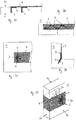
- FIG. 3H and 3I is a possible application of the in the Figures 3F and 3G shown arrangement.
- this is a concrete slab 10, which has a plurality of reinforcing ribs 11, ie T-shaped sections.
- the reinforcing ribs 11 had in the region of their joints with the concrete slab 10 holes 3, which are designed so that in each case two holes in the extension of their drilling axes are interconnected.
- a plurality of grooves extend along the surface of the concrete slab. Similar to the embodiments described above, boreholes and grooves are filled with fiber bundles or fiber strands of the fiber bundle and adhesive.
- a surface reinforcement in the form of a fabric 7 is attached. This fabric is glued in particular all over the surface with the underlying surface.
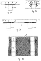
- FIGS. 4A (Cross-section) and 4B (top view) a further embodiment of the invention, in which arrangements, as for example in the FIGS. 2A and 2B are shown are attached to a support structure 1 at regular intervals.
- the arrangements can be mounted on a surface of the surface of the support structure or on multiple surfaces.
- a fabric 7 is glued to the surface of the support structure, at least with the arrangements, but in particular over its full area.
- the fabric can run continuously over corners and edges in the surface of the support structure.
- FIG. 5A shows a section through a non-inventive embodiment of a support structure 1 having a surface consisting of a plurality of surfaces 2a, 2b, 2c, etc. and a first bore 3a, which extends from the surface 2a in the inner region of the support structure.
- the second bore 3b extends from the surface 2b in the inner region of the support structure.
- the surface 2b faces away from the surface 2a.
- a groove 5 extends along the surface of the support structure towards the entry point of the other bore in the support structure. The groove, which thus connects the two inlet holes of the holes with each other, runs in particular on the shortest path between the two holes.
- the groove assumes a different course between the bores, for example to ensure the most uniform possible distribution of force.
- a fiber bundle 4 which opens with its loose ends in the two holes 3a and 3b. Both in the holes and in the groove is adhesive 12 for fixing the fiber bundle.
- FIG. 5B A similar embodiment not according to the invention as in FIG. 5A is also in FIG. 5B represented here, wherein here the fiber bundle surrounds a reinforcing rib 11 of a structure 1.
- FIG. 6A shows a section through a further non-inventive embodiment of the invention, which is a modification of the embodiment FIG. 5A equivalent.
- the embodiment in FIG. 6A two holes 3a, 3b in different, mutually remote surfaces 2a, 2b of the surface of the support structure, wherein the two holes 3a and 3b are arranged so that they are connected to each other in the extension of their respective drilling axes.
- the entry holes of the two Boreholes 3a and 3b are as in FIG. 5A connected to each other via a groove 5.
- Both the holes 3a, 3b and the groove 5 contain an adhesive 12 and a fiber bundle 4.
- the fiber bundle is in particular arranged so that its two ends overlap. This overlap may be in the hole or anywhere in the groove.
- the length of the overlapping region of the fiber bundle is in particular chosen so that a possible seamless power transmission is ensured and is about 5 to 50 cm.
- the preferred embodiments allow a higher efficiency of reinforcement and a much better utilization of the fiber bundle.
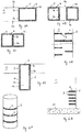
- FIG. 6C shows modifications of the embodiment not according to the invention, as in FIG. 6A is described. Shown here are arrangements according to the invention, as they can be used for example to reinforce a rectangular column as part of a support structure.
- FIG. 6C shows that it is also possible that the fiber bundle 4 is repeatedly passed through a bore, but to run in two different grooves from the entry of the first bore to that of the second bore.
- the embodiment can FIG. 6C also be created by the projecting beyond the bore part of the fiber bundle is divided into two fiber strands, which then extend in different grooves.
- FIG. 6D shows a non-inventive modification of the embodiment, as shown in FIG. 5B is shown, in which case the fiber bundle 4 completely surrounds the reinforcing rib 11.
- FIG. 6E shows a non-inventive side view of a support structure, which in the Figures 6A, 6B and 6C illustrated variants of the arrangement comprises. Depending on the requirements, the different variants can be combined with each other, or several identical arrangements are continuously attached to a support structure.
- FIG. 6G shows a non-inventive support structure 1 comprising a bottom plate 10 and a wall created thereon, the wall is provided in its lower portion with a plurality of arrangements, which from those FIG. 6A correspond.
- a fabric for additional reinforcement of the support structure can be attached via these arrangements (not shown here).
- FIG. 6F shows a cylindrical column comprising a plurality of arrangements.
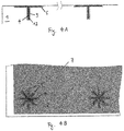
- FIG. 7A shows a detailed view of a section of a non-inventive support structure 1 having a surface consisting of a plurality of surfaces 2a, 2b, 2c, wherein from a surface 2a of a bore 3 extends into an inner region of the support structure.
- the support structure 1 is provided on the surface 2a, from which the bore extends into an inner region of the support structure, with a groove 5 which extends from the bore in a direction on the surface.
- the groove 5 extends over each edge 8, which connects the two surfaces 2 a and 2 c, and 2 c and 2 b of the surface of the structure together, and this one edge 8 has in the interior of the groove 5 a rounding 9.
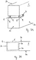
- FIG. 7B shows a section through a portion of a non-inventive support structure 1, which has two holes 3a, 3c in different, mutually remote surfaces 2a, 2c of the surface of the support structure, wherein the two holes 3a and 3c are arranged so that they in the extension their respective drilling axes are interconnected.
- the inlet holes of the two holes 3a and 3b are connected to each other via a groove 5.
- the edges 8 each have a rounding 9. Again, the respective transitions from the bore into the groove may have a rounding according to the above description.
- Concrete cubes with an edge length of 20 cm were produced as test specimens, using concrete from the same batch for all cubes.
- the concrete cubes were stored for 28 days at 23 ° C and 50% relative humidity.
- the concrete cubes were sanded off on one side to remove cement slurry.
- a hole with a diameter of 20 mm and a depth of 100 mm was attached.
- Two concrete cubes were left without drilling. Starting from the hole, eight grooves with an angle grinder were placed on the concrete cubes evenly around the hole. The grooves were 5 mm wide and 5 mm deep and extended over a length of 8 cm. The angle between the grooves was 45 ° each. With four concrete cubes, only five grooves each were mounted semicircularly.
- Sikadur®-330 commercially available from Sika Nurse AG, with a mean layer thickness of about 1 mm was applied to the machined surface of the concrete cubes without drilling.
- the hole was filled from bottom to top and the grooves filled with Sikadur®-330. It was ensured that no air was trapped in the hole.
- a fiber bundle with a length of 20 cm and a fiber cross-sectional area of about 25 mm 2 was completely impregnated using a brush with Sikadur® 300 from Sika für AG. Subsequently, a cable tie was attached to a loose end of the impregnated fiber bundle and tightened and cut to length. With the help of a knitting needle, which was hooked to the cable tie, the fiber bundle was inserted all the way into the hole. The protruding end of the fiber bundle was divided into fiber strands, the number of fiber strands having to correspond to those of the previously mounted grooves, and inserted into the grooves. In the concrete cubes without grooves, the protruding end of the fiber bundle was fanned out evenly and spread on the machined surface of the concrete cube.
- a fabric provided with SikaWrap® 300 C NW was laminated in the area of the last 20 cm of its loose ends by means of a paint roller with Sikadur®-300.
- a laminated loose end was placed on the machined surface of the concrete cube and pressed there with a paint roller.
- Sikadur®-330 was applied over the attached tissue using a dental trowel.
- the fabric was looped over and the other loose and laminated end was placed on the same spot of the concrete cube so that the two ends of the fabric came to lie one above the other. Again, the fabric was pressed with the paint roller. With a spatula of the width of the concrete cube, excess adhesive was removed from the specimen.
- test specimens thus produced were left for 7 days at 23 ° C and 50% relative humidity, so that the adhesive could cure.
- specimens were also made with fiber bundles of glass fibers with a fiber cross-sectional area of about 25 mm 2 .
- the tensile shear strength of different test specimens was measured according to ISO 527-4 / EN 2561 with a measuring speed of 2 mm / min at 23 ° C and a relative humidity of 50%.
- the tensile shear strength of the bond was tested by placing the loop formed by the SikaWrap-300C NW fabric around a steel pipe connected to the moving frame of the testing machine.
Description
Die Erfindung betrifft das Gebiet der Verstärkung von Tragstrukturen, vorzugsweise durch Anbringen von Oberflächenbewehrung, insbesondere der Krafteinleitung in die Oberflächenbewehrung.The invention relates to the field of reinforcement of support structures, preferably by applying surface reinforcement, in particular the introduction of force into the surface reinforcement.
Verfahren, um den Tragwiderstand bestehender Tragstrukturen, typischerweise Stahlbetonbauteile, zu vergrössern, werden bereits seit vielen Jahren verwendet. Oftmals geschieht dies mittels oberflächlich angebrachter zusätzlicher Bewehrung. Weitgehend durchgesetzt haben sich dabei überwiegend oberflächlich aufgeklebte Bewehrungen aus Faserverbundwerkstoffen. Die Wirksamkeit dieser Oberflächenbewehrung wird im Normalfall durch die maximal vom Beton auf die Bewehrung übertragbare Kraft begrenzt.Methods to increase the bearing capacity of existing support structures, typically reinforced concrete components, have been used for many years. Often this happens by means of superficially mounted additional reinforcement. For the most part, superficially bonded reinforcements made of fiber composite materials have prevailed. The effectiveness of this surface reinforcement is normally limited by the maximum transferable from the concrete to the reinforcement force.
Verschiedenste Methoden zur Verbesserung der Kraftübertragung von der Tragstruktur auf die Oberflächenbewehrung sind bekannt. Ein weit verbreitetes Verfahren besteht darin, Faserbündel in eine Bohrung in der Tragstruktur einzuführen und dort zu verankern und ein über die Oberfläche überstehendes Ende des Faserbündels auszubreiten bzw. auszufächern und auf der Oberfläche aufzukleben. Anschliessend kann dann eine Oberflächenbewehrung auf die verstärkte Tragwerksoberfläche aufgeklebt werden. Alternativ kann zuerst auch die Oberflächenbewehrung auf die Tragwerksoberfläche aufgeklebt werden, sodass bei einem danach angebrachten Anker aus einem Faserbündel, das überstehende Ende dieses auf die Oberfläche der Oberflächenbewehrung aufgeklebt wird. Bei Oberflächenbewehrungen mit mehreren Lagen wird zur besseren Kraftübertragung vielfach empfohlen, die Anker zwischen den Gewebelagen auszubreiten.Various methods for improving the transmission of force from the support structure to the surface reinforcement are known. A widely used method is to introduce fiber bundles into a bore in the support structure and to anchor them there and to spread out or fan out an end of the fiber bundle projecting beyond the surface and to stick it to the surface. Subsequently, a surface reinforcement can then be glued to the reinforced structural surface. Alternatively, the surface reinforcement may first be glued to the structural surface, so that when an anchor attached thereto from a fiber bundle, the protruding end of this is glued to the surface of the surface reinforcement. In the case of surface reinforcements with multiple layers, it is often recommended for better force transmission to spread the anchors between the fabric layers.
Die Wirksamkeit dieser Massnahme ist experimentell nachgewiesen bleibt jedoch aus verschiedenen Gründen beschränkt.The effectiveness of this measure has been experimentally proven to be limited for various reasons.
Einerseits wird die oberflächennahe potenzielle Bruchfläche von jedem Anker nur an einer Stelle (beim Schaft) durchbrochen. Der Widerstand dieser potenziellen Bruchfläche wird damit nur in beschränktem Mass vergrössert. Andererseits ist die Kraftübertragung von den auf der Oberfläche ausgebreiteten Fasern des Faserbündels auf die Fasern des Gewebes nicht optimal. Der sehr dünne, von den Fasern des Faserbündels auf der Oberfläche gebildete Faserverbundwerkstoff kann nur in Zugrichtung wesentlich belastet werden. Bei Belastung auf Druck knickt der Faserverbundwerkstoff, bei Belastung auf Schub und Biegung können nur sehr geringe Kräfte übertragen werden. Es sind daher nur die annähernd in Zugrichtung der Oberflächenbewehrung liegenden Fasern voll wirksam. Diese machen nur einen kleinen Teil des Fasebündelquerschnitts aus und decken nur einen kleinen Teil der Breite der Oberflächenbewehrung ab.On the one hand, the near-surface potential fracture surface of each anchor is broken at only one point (at the shank). The resistance of this potential fracture surface is thus increased only to a limited extent. On the other hand, the transmission of force from the fibers of the fiber bundle spread on the surface to the fibers of the fabric is not optimal. The very thin, formed by the fibers of the fiber bundle on the surface fiber composite material can be charged only in the pulling direction substantially. When loaded under pressure, the fiber composite material buckles, but when subjected to thrust and bending, only very small forces can be transmitted. Therefore, only the approximately in the pulling direction of the surface reinforcement fibers are fully effective. These make up only a small part of the fiber bundle cross-section and cover only a small part of the width of the surface reinforcement.
Ein weiterer Nachteil des bekannten Verfahrens liegt darin, dass das über die Oberfläche überstehende Ende des Faserbündels auf der Oberfläche selbst ausgebreitet ist und somit durch Vorsprünge, überstehende Verformungen an der Oberfläche verursacht werden, welche einerseits die Optik eines Bauwerks stören können, andererseits aber auch technische Nachteile mit sich bringen können. Beispielsweise können Erhebungen in einer sonst ebenen Oberfläche dazu führen, dass Wasser, insbesondere Regenwasser, oder Schnee, aber auch Schmutz sich an diesen Erhebungen ansammeln und die langfristige Wirkung
Die Aufgabe der vorliegenden Erfindung ist es daher eine Anordnung und ein Verfahren bereitzustellen, wonach eine Verbesserung der Krafteinleitung in eine Oberflächenbewehrung erreicht werden soll.The object of the present invention is therefore to provide an arrangement and a method according to which an improvement in the introduction of force into a surface reinforcement is to be achieved.
Weiterhin ist es die Aufgabe der vorliegenden Erfindung die Kraftübertragung von Faserbündeln, welche an einem Tragwerk angebracht sind, insbesondere in einen Oberflächen- oder in einen oberflächennahen Bereich zu verbessern.Furthermore, it is the object of the present invention to improve the power transmission of fiber bundles, which are attached to a supporting structure, in particular in a surface or in a near-surface region.
Überraschenderweise wurde gefunden, dass mittels einer Anordnung nach Anspruch 1 und einem Verfahren nach Anspruch 8 diese Aufgabe gelöst werden kann.Surprisingly, it has been found that by means of an arrangement according to
Kern der Erfindung ist demnach eine Anordnung umfassend eine Tragstruktur mit einer Oberfläche bestehend aus einer oder mehreren Flächen, wobei von mindestens einer Fläche aus eine Bohrung in einen inneren Bereich der Tragstruktur verläuft, und diese Bohrung mit einem Klebstoff und mit einem Abschnitt eines über diese Bohrung hinausragenden Faserbündels gefüllt ist, wobei die Tragstruktur an der mindestens einen Fläche, von welcher aus die Bohrung in einen inneren Bereich der Tragstruktur verläuft, mit mehreren Nuten versehen ist, welche sich ausgehend von der Bohrung in einem Bereich von mindestens einem Kreissektor erstrecken und sich der hinausragende Teil des Faserbündels nach Fasersträngen aufgeteilt zumindest teilweise in den Nuten befindet und darin mit dem Klebstoff befestigt ist.The core of the invention is therefore an assembly comprising a support structure having a surface consisting of one or more surfaces, wherein extending from at least one surface of a bore in an inner region of the support structure, and this bore with an adhesive and with a portion of a via this bore protruding fiber bundle is filled, wherein the support structure is provided on the at least one surface, from which the bore extends in an inner region of the support structure, with a plurality of grooves extending from the bore in a region of at least one circular sector and the protruding part of the fiber bundle divided into fiber strands at least partially located in the grooves and is secured therein with the adhesive.
Als Tragstruktur wird hier ein Element oder ein Teil eines Elements bezeichnet, welches Kräften ausgesetzt ist. Typischerweise ist die Tragstruktur ein Bauwerk oder ein Bestandteil eines Bauwerks, beispielsweise eine Platte, eine Decke, eine Wand, eine Säule, eine Rippe, ein Balken oder dergleichen. Die Tragstruktur besteht dabei typischerweise aus Beton, insbesondere aus Stahlbeton, kann aber auch aus Ziegel- oder anderen Mauersteinen, aus Holz, aus Stahl oder aus anderen Materialien sowie aus beliebigen Kombinationen dieser Materialien bestehen. Typischerweise handelt es sich bei den Bauwerken um Bauwerke des Hoch- und Tiefbaus, wie Häuser, Brücken, Tunnels, Staudämmen, Sportanlagen, etc.As a support structure here is an element or part of an element referred to which is exposed to forces. Typically, the support structure is a building or component of a building, such as a slab, ceiling, wall, pillar, rib, beam or the like. The support structure is typically made of concrete, especially reinforced concrete, but may also consist of bricks or other bricks, wood, steel or other materials and any combination of these materials. Typically, the buildings are civil engineering works, such as houses, bridges, tunnels, dams, sports facilities, etc.
Beim Faserbündel handelt es sich um eine lose Anordnung von im Wesentlichen gleichgerichteten Einzelfasern bzw. Filamenten, insbesondere aus Kohle (Carbon), Glas, Basalt, Aramid, Stahl oder anderen anorganischen oder organischen Materialien. Bevorzugt handelt es sich bei den Fasern um Kohlefasern.The fiber bundle is a loose arrangement of substantially rectified individual fibers or filaments, in particular of carbon (carbon), glass, basalt, aramid, steel or other inorganic or organic materials. Preferably, the fibers are carbon fibers.
Der Stärke des Faserbündels ist abhängig vom Einsatzbereich und von den Kräften, welche durch das Faserbündel übertragen werden sollen. Besteht das Faserbündel aus Kohlefasern, umfasst dieses insbesondere 1000 bis 50'000 Einzelfasern, welche jeweils selbst einen Durchmesser im Bereich von 5 bis 10 µm aufweisen. Ein typisches Faserbündel weist vorzugsweise eine Querschnittsfläche von 20 bis 70 mm2, insbesondere von 25 bis 40 mm2, auf.The thickness of the fiber bundle depends on the area of use and on the forces which are to be transmitted through the fiber bundle. If the fiber bundle consists of carbon fibers, this comprises, in particular, 1000 to 50,000 individual fibers, each themselves having a diameter in the range from 5 to 10 have μm. A typical fiber bundle preferably has a cross-sectional area of from 20 to 70 mm 2 , in particular from 25 to 40 mm 2 .
Das Anbringen des Faserbündels an der Tragstruktur erfolgt typischerweise dadurch, dass in einem ersten Schritt an der gewünschten Stelle eine Bohrung angebracht wird, welche der Aufnahme eines Abschnitts des Faserbündels dient. Die Bohrung kann dabei mit beliebigen Mitteln erstellt werden, wobei solche Mittel dem Fachmann bestens bekannt sind. Die Dimensionen der Bohrung ergeben sich aus der Stärke und der Länge des Faserbündels und diese wiederum von den Anforderungen, welche an die erfindungsgemässe Anordnung gestellt werden. Typischerweise weist eine geeignete Bohrung einen Durchmesser von 1 bis 5 cm, insbesondere von 1.5 bis 3 cm auf und eine Tiefe von 5 bis 30 cm, insbesondere von 7 bis 20 cm.The attachment of the fiber bundle to the support structure is typically carried out by attaching, in a first step, at the desired location, a bore which serves to receive a portion of the fiber bundle. The bore can be created by any means, such means are well known to those skilled. The dimensions of the bore resulting from the strength and the length of the fiber bundle and this in turn of the requirements that are imposed on the inventive arrangement. Typically, a suitable bore has a diameter of 1 to 5 cm, in particular 1.5 to 3 cm and a depth of 5 to 30 cm, in particular from 7 to 20 cm.
In einem weiteren Schritt wird ausgehend von der Bohrung bzw. von der Eintrittsstelle der Bohrung in die Oberfläche der Tragstruktur eine oder mehrere Nuten angebracht. Auch die Nuten können mit beliebigen Mitteln erstellt werden, beispielsweise mit einem Winkelschleifer.In a further step, one or more grooves are made starting from the bore or from the point of entry of the bore into the surface of the support structure. The grooves can be created by any means, for example with an angle grinder.
Die Nuten sind dabei so dimensioniert, dass sie in ihrer Gesamtheit das Faserbündel, welches im Fall, dass mehrere Nuten vorhanden sind, in einzelne Faserstränge aufgeteilt sein kann, aufnehmen können.The grooves are dimensioned so that they in their entirety, the fiber bundle, which can be divided into individual fiber strands in the event that multiple grooves are present, can accommodate.
Die Anzahl und Anordnung der Nuten ist dabei abhängig vom Einsatzbereich der erfindungsgemässen Anordnung.The number and arrangement of the grooves is dependent on the application of the inventive arrangement.
Nach Anbringen der Bohrung und den mehreren Nuten wird das Faserbündel in Bohrung und Nuten eingelegt und darin verklebt. Hierzu wird zuerst ein Klebstoff in die Bohrung und in die Nuten eingebracht.After attaching the bore and the plurality of grooves, the fiber bundle is inserted into the bore and grooves and glued therein. For this purpose, an adhesive is first introduced into the bore and into the grooves.
Danach wird das Faserbündel, welches vorab vorzugsweise mit einem Harz getränkt ist, so in die Bohrung eingebracht, dass ein Abschnitt des Faserbündels über die Bohrung hinausragt. Im Verlauf des Anbringens der erfindungsgemässen Anordnung an einem Tragwerk ragt der über die Bohrung hinausragende Abschnitt des Faserbündels in der Regel auch über die Oberfläche der Tragstruktur hinaus. Der Abschnitt des Faserbündels, welcher sich jedoch bei der montierten Anordnung in Mehreren Nuten befindet, ragt dann nicht mehr über die Oberfläche der Tragstruktur hinaus, wodurch eine einheitliche und glatte Oberfläche gewährleistet werden kann.Thereafter, the fiber bundle, which is preferably pre-impregnated with a resin, introduced into the bore so that a portion of the fiber bundle protrudes beyond the bore. In the course of attaching the inventive arrangement to a supporting structure protrudes beyond the bore portion of the fiber bundle usually also beyond the surface of the support structure out. However, the portion of the fiber bundle, which is in the assembled arrangement in multiple grooves, then does not protrude more beyond the surface of the support structure, whereby a uniform and smooth surface can be ensured.
Dieser hinausragende Abschnitt des Faserbündels wird zumindest teilweise in die mit Klebstoff versehene Nut eingelegt bzw. gleichmässig in eine der Anzahl der Nuten entsprechenden Anzahl Faserstränge aufgeteilt und in die Nuten eingelegt. Erfindungsgemäß werden das gesamte Faserbündel bzw. alle Faserstränge in mehrere Nuten eingelegt, so dass das Faserbündel an keiner Stelle über die Oberfläche der Tragstruktur hinausragt. Nach dem Einlegen des Faserbündels in die Nuten, kann das Faserbündel darin angedrückt werden. Aus dem Bohrloch oder aus den Nuten hervorquellender Klebstoff wird danach entfernt oder gleichmässig im Bereich der von der Anordnung betroffenen Oberfläche verteilt. Befinden sich nach dem Einlegen des Faserbündels noch Hohlräume in der Bohrung oder in den Nuten, können diese mit Klebstoff ausgefüllt werden. Das Einführen des Faserbündels in die Bohrung erfolgt insbesondere mit einem nadelartigen Gegenstand. Am Faserbündel kann zur besseren Führung mit dem nadelartigen Gegenstand eine Klammer, ein Kabelbinder oder dergleichen angebracht sein, an welchem der nadelartige Gegenstand eingehakt werden kann.This projecting portion of the fiber bundle is at least partially inserted into the adhesive groove or uniformly divided into a number of grooves corresponding number fiber strands and inserted into the grooves. According to the invention, the entire fiber bundle or all fiber strands are inserted into a plurality of grooves, so that the fiber bundle does not protrude beyond the surface of the support structure at any point. After inserting the fiber bundle in the grooves, the fiber bundle can be pressed in it. Adhesive material emerging from the wellbore or grooves is then removed or evenly distributed in the area of the surface affected by the assembly. Are there any cavities in the hole or in the grooves after inserting the fiber bundle, these can be filled with adhesive. The introduction of the fiber bundle into the bore takes place in particular with a needle-like object. On the fiber bundle, a clip, a cable tie or the like can be attached to which the needle-like object can be hooked for better guidance with the needle-like object.
Das Tränken des Faserbündels mit einem Harz vor dem Einlegen in Bohrung und Nuten hat den Vorteil, dass die Benetzung des gesamten Faserbündels mit Harz, auch im inneren Bereich, erreicht werden kann. Zur Gewährleistung einer optimalen Haftung zwischen Faserbündel und Tragstruktur weist das Harz zum Tränken des Faserbündels insbesondere die gleiche chemische Basis auf wie der Klebstoff zum Befestigen des Faserbündels in Bohrung und Nuten. Insbesondere handelt es sich sowohl beim Harz als auch beim Klebstoff um Epoxidharzzusammensetzungen. Es ist möglich, dass es sich beim Klebstoff und beim Harz um dieselbe Zusammensetzung handelt, wobei beim Harz die Viskosität typischerweise etwas niedriger eingestellt ist als beim Klebstoff, was wiederum der besseren Benetzung der Fasern dient.The impregnation of the fiber bundle with a resin prior to insertion in the bore and grooves has the advantage that the wetting of the entire fiber bundle with resin, even in the inner region, can be achieved. To ensure optimum adhesion between the fiber bundle and the support structure, the resin for impregnating the fiber bundle in particular has the same chemical basis as the adhesive for fastening the fiber bundle in the bore and grooves. In particular, both the resin and the adhesive are epoxy resin compositions. It is possible that the adhesive and the resin are the same composition, with the viscosity of the resin typically being set slightly lower than that of the adhesive, which in turn serves to better wet the fibers.
Sowohl beim Klebstoff zum Befestigen des Faserbündels in Bohrung und Nut als auch beim Harz zum allfälligen Tränken des Faserbündels wird bevorzugt eine zweikomponentige Epoxidharzzusammensetzung verwendet. Geeignete Epoxidharzzusammensetzungen sind beispielsweise unter den Handelsnamen Sikadur® kommerziell erhältlich sind von Sika Schweiz AG.Both the adhesive for fixing the fiber bundle in the bore and groove and the resin for the possible impregnation of the fiber bundle, a two-component epoxy resin composition is preferably used. Suitable epoxy resin compositions are, for example, under the trade names Sikadur ® are commercially available from Sika Switzerland AG.
Die Verklebungsstellen an der Tragstruktur sind vorzugsweise sauber, trocken, staub- und fettfrei. Abhängig von den Materialien, aus welchen die Tragstruktur besteht, können geeignete Reinigungsmassnahmen oder Vorbehandlungen angewendet werden.The bonding sites on the support structure are preferably clean, dry, free of dust and grease. Depending on the materials of which the support structure is made, suitable cleaning measures or pretreatments may be used.
Die erfindungsgemässe Anordnung kann für unterschiedliche Zwecke an einer Tragstruktur angebracht werden. Insbesondere dient dabei die Anordnung selbst als Verstärkung für die Tragstruktur und/oder sie dient als Anker bzw. als Verankerung für eine an der Tragstruktur angebrachten Oberflächenbewehrung.The inventive arrangement can be attached to a support structure for different purposes. In particular, the arrangement itself serves as a reinforcement for the support structure and / or serves as an anchor or as an anchorage for a surface reinforcement attached to the support structure.
Dient die Anordnung als Verankerung für eine an der Tragstruktur angebrachten Oberflächenbewehrung, so weist sie mehrere Nuten auf, welche sich ausgehend von der Bohrung entlang der Oberfläche erstrecken. Vorzugsweise beträgt in diesem Fall die Anzahl Nuten pro Bohrung 2 bis 16, insbesondere 6 bis 10.If the arrangement serves as an anchorage for a surface reinforcement attached to the support structure, then it has several grooves which extend from the bore along the surface. In this case, the number of grooves per bore is preferably 2 to 16, in particular 6 to 10.
Die Nuten sind dabei insbesondere kreisförmig und in regelmässigen Abständen um die Bohrung angeordnet. Erfindungsgemäß sind die Nuten in einem Kreissektor um die Bohrung angeordnet, wobei der Kreissektor bevorzugt einen Mittelpunktswinkel von 60 bis 360° aufweist. Die Anordnung der Nuten richtet sich in der Regel nach der Belastungsrichtung der Oberflächenbewehrung, welche über die erfindungsgemässe Anordnung als Anker bzw. Verankerung mit der Tragstruktur verklebt wird. Insbesondere breiten sich die Nuten in diesem Fall in Zugrichtung der Oberflächenbewehrung aus.The grooves are in particular circular and arranged at regular intervals around the bore. According to the invention, the grooves are arranged in a circular sector around the bore, wherein the circular sector preferably has a center angle of 60 to 360 °. As a rule, the arrangement of the grooves depends on the loading direction of the surface reinforcement, which is adhesively bonded to the supporting structure via the arrangement according to the invention as an anchor or anchoring. In particular, the grooves extend in this case in the pulling direction of the surface reinforcement.
In einer weiteren Ausführungsform kann die Anordnung selbst zur Verstärkung einer Tragstruktur dienen. In diesem Fall werden insbesondere mehrere der beschriebenen Anordnungen in regelmässigen Abständen an einer Tragstruktur angebracht. Auch in diesem Fall weist die erfindungsgemässe Anordnung wie vorhergehend beschrieben mehrere Nuten auf. Bevorzugt weist die Anordnung in diesem Fall eine zweite Bohrung auf, welche in einen inneren Bereich der Tragstruktur verläuft, wobei sich die zweite Bohrung auf derselben oder auf einer anderen Fläche der Oberfläche befinden kann. Zumindest eine der mehreren Nuten verläuft dabei vom Eintrittsort der einen, also er ersten, Bohrung entlang der Oberfläche der Tragstruktur hin zum Eintrittsort der zweiten Bohrung, die beiden Bohrungen sind also im Oberflächenbereich der Tragstruktur über mindestens eine Nut miteinander verbunden. Befinden sich die beiden Bohrungen nicht auf derselben Fläche der Oberfläche der Tragstruktur, d.h. wenn also beispielsweise eine oder mehrere Kanten oder Ecken zwischen den Flächen liegen, verläuft die mindestens eine Nut auch über diese Kanten oder Ecken.In a further embodiment, the arrangement itself can serve to reinforce a supporting structure. In this case, in particular, several of the arrangements described are mounted at regular intervals on a support structure. Also in this case, the inventive arrangement as previously described on several grooves. In this case, the arrangement preferably has a second bore which extends into an inner region of the support structure, wherein the second bore may be located on the same or on another surface of the surface. At least one of the plurality of grooves extends from the entry of one, so he first, bore along the surface of the support structure towards the entry of the second bore, so the two holes are connected to each other in the surface region of the support structure via at least one groove. If the two holes are not on the same surface of the surface of the support structure, i. If, for example, one or more edges or corners lie between the surfaces, the at least one groove also extends over these edges or corners.
Befinden sich die beiden Bohrungen an sich gegenseitig abgewandten Flächen einer Tragstruktur ist es möglich, dass die zwei Bohrungen in der Verlängerung ihrer jeweiligen Bohrachsen miteinander verbunden sind.If the two bores are located on mutually opposite surfaces of a support structure, it is possible for the two bores in the extension of their respective boring axes to be connected to one another.
Beispielsweise ist dies der Fall, wenn die erfindungsgemässe Anordnung im Bereich der Stirnseite einer mindestens einseitig freistehenden Wand angebracht werden soll. In diesem Fall können die zwei Bohrungen dadurch erstellt werden, dass die Wand an einer Stelle durchbohrt wird. Eine Nut wird dann insbesondere so angebracht, dass sie den Eintrittsort und den Austrittsort der Bohrung in der Wand miteinander über die Stirnseite hinweg verbindet. Der Austrittsort der einen Bohrung in der Wand stellt dabei den Eintrittsort der zweiten Bohrung dar.This is the case, for example, if the arrangement according to the invention is to be applied in the region of the end face of a wall which is free-standing at least on one side. In this case, the two holes can be made by drilling the wall in one place. In particular, a groove is then positioned to connect the entry location and exit location of the bore in the wall with each other across the face. The exit location of a hole in the wall represents the entry point of the second hole.
Auch bei einem derartigen Einsatz der erfindungsgemässen Anordnung kann eine Oberflächenbewehrung an der Oberfläche der Tragstruktur angebracht werden.Even with such an application of the inventive arrangement, a surface reinforcement can be attached to the surface of the support structure.
Unabhängig von der Beschaffenheit der erfindungsgemässen Anordnung, wird die Oberflächenbewehrung vorzugsweise so angebracht, dass sie den sich an der Oberfläche der Tragstruktur in mindestens einer Nut verlaufenden Abschnitt des Faserbündels und die Bohrung bzw. den Eintrittsort der Bohrung in die Oberfläche gesamthaft abdeckt und über diesen gesamten Bereich mit der Oberfläche der Tragstruktur verklebt ist.Regardless of the nature of the arrangement according to the invention, the surface reinforcement is preferably arranged so that it extends in at least one groove on the surface of the support structure Section of the fiber bundle and the bore or the entry of the bore in the surface covering a whole and is glued over this entire area with the surface of the support structure.
Als Oberflächenbewehrung kommen insbesondere Lamellen oder Gewebe in Frage, welche entlang der Oberfläche einer Tragstruktur verlaufen und mit dieser, insbesondere vollflächig, verklebt sind. Als Lamellen eignen sich insbesondere unidirektional faserverstärkte Kunststoff-Flachbandlamellen. Die Faserverstärkung erfolgt üblicherweise durch Kohlefasern, kann jedoch wie beim Faserbündel auch, durch Glas, Basalt oder Aramid erfolgen. Als Kunststoffmatrix dient insbesondere eine Epoxidharzmatrix. Ebenfalls geeignet kann eine Kunststoffmatrix auf Polyurethan, Vinylester, Polyacrylat oder anderen Zusammensetzungen basieren, welche strukturelle Eigenschaften aufweisen. Geeignete faserverstärkte Kunststoff-Flachbandlamellen sind beispielsweise unter dem Handelsnamen Sika® CarboDur® kommerziell erhältlich sind von Sika Schweiz AG.
Als Gewebe eignet sich vorzugsweise ein, insbesondere unidirektionales, Kohlefasergewebe, wobei auch dieses aus Glas-, Basalt- oder Aramidfasern bestehen kann. Im Gegensatz zu den faserverstärkten Kunststoff-Flachbandlamellen, wird das Gewebe typischerweise nicht bereits in einer ausgehärteten Kunststoffmatrix auf die Oberfläche aufgetragen, sondern vor oder nach dem Anbringen an der Oberfläche mit einer härtbaren Zusammensetzung versehen. Bei der härtbaren Zusammensetzung handelt es sich insbesondere um eine Epoxidharzzusammensetzung, wobei auch hier Polyurethan oder Polyacrylat verwendet werden könnte.
Als Gewebe eignet sich insbesondere ein Kohlefasergewebe, wie es beispielsweise unter der Bezeichnung SikaWrap® kommerziell erhältlich ist von Sika Schweiz AG.In particular, lamellae or tissue come into consideration as surface reinforcement, which run along the surface of a support structure and are adhesively bonded thereto, in particular over the entire surface. In particular, unidirectionally fiber-reinforced plastic flat strip lamellae are suitable as lamellae. The fiber reinforcement is usually made by carbon fibers, but can also be done as in the fiber bundle, by glass, basalt or aramid. The plastic matrix used is in particular an epoxy resin matrix. Also suitably a plastic matrix may be based on polyurethane, vinyl ester, polyacrylate or other compositions having structural properties. Suitable fiber-reinforced plastic ribbon strips are, for example, under the trade name Sika ® CarboDur ® are commercially available from Sika Switzerland AG.
The fabric is preferably a, in particular unidirectional, carbon fiber fabric, which also may consist of glass, basalt or aramid fibers. In contrast to the fiber-reinforced plastic flat strip lamellae, the fabric is typically not already applied to the surface in a cured plastic matrix, but provided with a curable composition before or after attachment to the surface. The curable composition is in particular an epoxy resin composition, polyurethane or polyacrylate could also be used here.
As fabric is particularly suitable a carbon fiber fabric, as it is commercially available for example under the name SikaWrap® from Sika Switzerland AG.
Sowohl als Kunststoffmatrix für die faserverstärkten Kunststoff-Flachbandlamellen als auch zur Verklebung dieser oder des Gewebes mit der Tragstruktur werden vorzugsweise zweikomponentige Epoxidharzzusammensetzungen verwendet, wie sie beispielsweise unter den Handelsnamen Sikadur® kommerziell erhältlich sind von Sika Schweiz AG.Both as a plastic matrix for the fiber-reinforced plastic ribbon strips as well as for bonding these or the fabric to the support structure are preferably bicomponent Epoxy resin compositions used, as they are commercially available for example under the trade names Sikadur® from Sika Switzerland AG.
Wie bereits vorhergehend beschrieben ist es möglich, dass das Faserbündel in mehreren Nuten über Kanten und/oder Ecken verläuft, welche unterschiedliche Flächen der Oberfläche der Tragstruktur miteinander verbinden. Handelt es sich dabei um eine Kante, weist diese Kante im Inneren der Nut vorzugsweise eine Abrundung auf. Der Radius der Abrundung beträgt insbesondere etwa 0.5 bis 10 cm, insbesondere 1 bis 5 cm.As already described above, it is possible that the fiber bundle extends in several grooves over edges and / or corners which connect different surfaces of the surface of the support structure with each other. If this is an edge, this edge preferably has a rounding in the interior of the groove. The radius of the rounding is in particular about 0.5 to 10 cm, in particular 1 to 5 cm.
Durch die Abrundung der Kante wird das Faserbündel, welches in Bohrung und Nut eingelegt ist, geschont, wodurch es zu weniger Faserbrüchen kommt und eine verbesserte Kraftübertragung möglich ist. Meist bevorzugt sind unabhängig von der jeweiligen Ausführungsform der vorliegenden Erfindung alle Kanten der Tragstruktur, über welche eine Nut mit Faserbündel verlaufen soll, innerhalb der Nut abgerundet.By rounding the edge of the fiber bundle, which is inserted in the bore and groove, spared, resulting in fewer fiber breaks and improved power transmission is possible. Most preferably, regardless of the particular embodiment of the present invention, all edges of the support structure, over which a groove with fiber bundle is to extend, are rounded within the groove.
Weiterhin ist es auch möglich, dass auch der Übergang von der Bohrung in die Nut eine Abrundung gemäss vorhergehender Beschreibung aufweist.Furthermore, it is also possible that the transition from the bore into the groove has a rounding according to the preceding description.
Die erfindungsgemässe Anordnung und ein Verfahren zu ihrer Anwendung werden typischerweise in der Verstärkung von bestehenden Tragstrukturen eingesetzt, beispielweise bei Renovation, Instandstellung oder bei der nachträglich an Tragstrukturen angebrachten Erdbebenverstärkung. Handelt es sich bei der Tragstruktur um Stahlbetonbauwerk erfolgt die Verstärkung beispielsweise dort, wo die Stahlarmierung unzureichend ist oder wo sie durch ein unvorhergesehenes Ereignis Schaden genommen hat.The inventive arrangement and a method for their application are typically used in the reinforcement of existing support structures, for example, during renovation, repair or later attached to support structures seismic reinforcement. If the support structure is a reinforced concrete structure, reinforcement takes place, for example, where the steel reinforcement is inadequate or where it has been damaged by an unforeseen event.
Ein erfindungsgemässes Verfahren zur Verstärkung einer Tragstruktur mit einer Oberfläche bestehend aus einer oder mehreren Flächen, umfasst demnach die Schritte:
- ▪ Erstellen mindestens einer Bohrung ausgehend von einer Fläche der Tragstruktur in einen inneren Bereich der Tragstruktur,
- ▪ Erstellen mehrerer Nuten ausgehend von der Bohrung in mindestens eine Richtung auf der Oberfläche der Tragstruktur, welche sich ausgehend von der Bohrung in einem Bereich von mindestens einem Kreissektor erstrecken,
- ▪ Einbringen eines Klebstoffs in die mindestens eine Bohrung,
- ▪ Einführen eines Faserbündels in die Bohrung, sodass ein Abschnitt des Faserbündels über die Bohrung hinausragt,
- ▪ Aufteilen des hinausragenden Teils des Faserbündels nach Fasersträngen,
- ▪ Mindestens teilweises Einlegen der Faserstränge in die mehrere Nuten,
- ▪ Befestigung der Faserstränge in den Nuten mittels Klebstoff.
- Creating at least one bore starting from a surface of the support structure in an inner region of the support structure,
- Creating a plurality of grooves starting from the bore in at least one direction on the surface of the support structure, which extend from the bore in a region of at least one circular sector,
- Introducing an adhesive into the at least one bore,
- Introducing a fiber bundle into the bore such that a portion of the fiber bundle protrudes beyond the bore,
- Dividing the protruding part of the fiber bundle into fiber strands,
- At least partially inserting the fiber strands into the plurality of grooves,
- ▪ Attaching the fiber strands in the grooves by means of adhesive.
Entsprechend der vorhergehenden Beschreibung der erfindungsgemässen Anordnung, kann das Verfahren weitere Schritte umfassen.According to the preceding description of the arrangement according to the invention, the method may comprise further steps.
Insbesondere wird das Faserbündel vor dem Einführen in die Bohrung und dem Einlegen in die Nuten mit einem Harz getränkt.In particular, the fiber bundle is impregnated with a resin prior to insertion into the bore and insertion into the grooves.
Ist an der Tragstruktur eine Oberflächenbewehrung vorgesehen, umfasst das Verfahren weiterhin ein Schritt des Anbringens einer Oberflächenbewehrung an der Oberfläche der Tragstruktur, wobei über dem Abschnitt des Faserbündels, welcher in der Nut mittels Klebstoff befestigt wurde eine Oberflächenbewehrung, insbesondere eine Lamelle oder ein Gewebe, angebracht wird und mindestens im Bereich des Abschnitts des Faserbündels, welcher in der Nut mittels Klebstoff befestigt wurde mit der Oberfläche des Tragwerks verklebt wird.If a surface reinforcement is provided on the support structure, the method further comprises a step of attaching a surface reinforcement to the surface of the support structure, wherein a surface reinforcement, in particular a lamella or a fabric, is affixed over the portion of the fiber bundle which has been adhesively secured in the groove is glued and at least in the region of the portion of the fiber bundle, which was fixed in the groove by means of adhesive with the surface of the structure.
Anhand der Zeichnungen werden Ausführungsbeispiele der Erfindung näher erläutert. Die
Es zeigen:
-
Figuren 1 A : Tragstrukturen mit Bohrungen und Nuten und darin eingeklebten Faserbündeln bzw. Fasersträngen;bis 2C -
Figuren 3A bis 4B : Tragstrukturen mit Bohrungen und Nuten und darin eingeklebten Faserbündeln bzw. Fasersträngen sowie Oberflächenbewehrung; -
Figuren 5A bis 6F : Ausführungsformen von Tragstrukturen mit Bohrungen und Nuten und darin eingeklebten Faserbündeln bzw. Fasersträngen; -
Figuren 7A und 7B
-
Figures 1 A to 2C : Supporting structures with bores and grooves and fiber bundles or fiber strands glued therein; -
FIGS. 3A to 4B : Supporting structures with bores and grooves and fiber bundles or fiber strands glued therein and surface reinforcement; -
FIGS. 5A to 6F Embodiments of support structures with holes and grooves and fiber bundles or fiber strands glued therein; -
FIGS. 7A and 7B : Detail views of support structures with rounded edges inside the groove.
In den Figuren sind nur die für das unmittelbare Verständnis der Erfindung wesentlichen Elemente gezeigt.In the figures, only the elements essential for the immediate understanding of the invention are shown.
-
Figur 1 A zeigt einen Schnitt durch eine Tragstruktur 1 mit einer Oberfläche bestehend aus mehreren Flächen 2a, 2b, 2c, wobei von der Fläche 2a aus, eine Bohrung 3 in einen inneren Bereich der Tragstruktur verläuft. Diese Bohrung ist gefüllt mit einem Klebstoff 12 und mit einem Abschnitt eines über diese Bohrung hinausragenden Faserbündels 4. Die Tragstruktur 1, ist an der Fläche 2a mit einer Nut 5 versehen, welche sich ausgehend von der Bohrung 3 bzw. vom Eintrittsort der Bohrung in die Fläche in eine Richtung auf der Oberfläche erstreckt. Der über die Bohrung hinausragende Teil des Faserbündels 4 befindet sich in der Nut 5 und ist darin mit Klebstoff 12 befestigt.Figure 1 A shows a section through asupport structure 1 having a surface consisting of a plurality ofsurfaces bore 3 extends in an inner region of the support structure. This bore is filled with an adhesive 12 and with a portion of a projecting beyond thisbore fiber bundle 4. Thesupport structure 1, is provided on the surface 2a with agroove 5, which extends from thebore 3 and from the entry point of the bore in the Area extends in one direction on the surface. The projecting beyond the bore part of thefiber bundle 4 is located in thegroove 5 and is fixed therein with adhesive 12. -
Figur 1B zeigt eine nicht erfindungsgemäße Draufsicht auf die inFigur 1A gezeigte Anordnung, wobei eine einzige Nut 5 von der Bohrung 3 in eine Richtung auf der Oberfläche verläuft. Weiterhin befindet sich der gesamte hinausragende Teil des Faserbündes in der Nut und ist darin mit Klebstoff 12 befestigt.FIG. 1B shows a non-inventive plan view of the inFigure 1A shown arrangement, wherein asingle groove 5 extends from thebore 3 in a direction on the surface. Furthermore, the entire protruding part of the fiber bundle is in the groove and is fixed therein with adhesive 12. -
Figur 1C zeigt ebenfalls eine Draufsicht auf die inFigur 1 A gezeigte Anordnung, wobei in dieser Ausführungsform mehrere Nuten 5 von der Bohrung 3 in verschiedene Richtungen auf der Oberfläche verlaufen. Der hinausragende Teil des Faserbündels 4 ist nach Fasersträngen aufgeteilt, wobei diese Faserstränge bevorzugt etwa die gleiche Stärke haben, und die Faserstränge befinden sich in den Nuten und sind darin mit Klebstoff 12 befestigt.Figure 1C also shows a plan view of the inFigure 1 A shown arrangement, wherein in this embodiment, a plurality ofgrooves 5 extend from thebore 3 in different directions on the surface. The protruding part of thefiber bundle 4 is divided into fiber strands, which fiber strands preferably have about the same thickness, and the fiber strands are in the grooves and are secured therein with adhesive 12. -
Figur 2A und 2B zeigt im Wesentlichen eine analoge Ausführungsform, wie sie in denFiguren 1A und 1C gezeigt ist, wobei die mehreren Nuten 5 ausgehend von der Bohrung 3 radial an der Oberfläche der Tragstruktur 1 verlaufen.FIGS. 2A and 2B shows essentially an analogous embodiment, as shown in theFIGS. 1A and 1C is shown, wherein the plurality ofgrooves 5 extend radially from thebore 3 to the surface of thesupport structure 1.
Unabhängig von den oben beschriebenen Ausführungsformen, stellt der Abschnitt des Faserbündels, welcher sich in der Bohrung befindet, insbesondere eines der beiden losen Enden des Faserbündels dar. Das andere lose Ende des Faserbündels stellt jenen Teil des Faserbündels dar, welcher über die Bohrung hinausragt bzw. welcher sich in den Nuten befindet und dort befestigt ist.Regardless of the embodiments described above, the portion of the fiber bundle, which is located in the bore, in particular one of the two loose ends of the fiber bundle. The other loose end of the fiber bundle represents that part of the fiber bundle, which projects beyond the bore or which is located in the grooves and fixed there.
In einer anderen, weniger bevorzugten Ausführungsform ist es auch möglich, ein Faserbündel insbesondere im Bereich seiner Mitte bzw. seines geometrischen Schwerpunkts umzufalten und so die beiden losen Enden des Faserbündels übereinander zu legen. Danach wird dann das Faserbündel, bevorzugt mit dem gefalteten Ende in die Bohrung eingeführt und die beiden losen Enden werden in die Nut eingelegt bzw. auf mehrere Nuten aufgeteilt.In another, less preferred embodiment, it is also possible to fold over a fiber bundle, in particular in the region of its center or its geometric center of gravity, and thus to overlay the two loose ends of the fiber bundle. Thereafter, the fiber bundle, preferably with the folded end is then inserted into the bore and the two loose ends are inserted into the groove or divided into a plurality of grooves.
In beiden Fällen ist jeweils der Abschnitt des Faserbündels, welcher sich in der Bohrung befindet, insbesondere in etwa gleich lang wie jener, welcher über die Bohrung hinausragt.In both cases, in each case the portion of the fiber bundle, which is located in the bore, in particular approximately the same length as that which projects beyond the bore.
In den
Eine Ausführungsform der erfindungsgemässen Anordnung, wie sie in den
Eine weitere Ausführungsform der Erfindung ist in
Eine Ausführungsform der vorliegenden Erfindung, bei welcher ebenfalls zwei Bohrungen vorhanden sind, welche in der Verlängerung ihrer Bohrachsen miteinander verbunden sind ist in den
In den
In den
Eine ähnliche nicht erfindungsgemäße Ausführungsform wie in
A similar embodiment not according to the invention as in
Im Allgemeinen und insbesondere auch in Bezug auf die Ausführungsformen der Erfindung, wie sie in den
Die
Die Nut 5 verläuft dabei über jeweils eine Kante 8, welche die zwei Flächen 2a und 2c, bzw. 2c und 2b der Oberfläche des Tragwerks miteinander verbindet, und diese eine Kante 8 weist im Inneren der Nut 5 eine Abrundung 9 auf.The
Im Folgenden sind Ausführungsbeispiele aufgeführt, welche die beschriebene Erfindung näher erläutern sollen. Selbstverständlich ist die Erfindung nicht auf diese beschriebenen Ausführungsbeispiele beschränkt.In the following, exemplary embodiments are listed which are intended to explain the described invention in more detail. Of course, the invention is not limited to these described embodiments.
Als Prüfkörper wurden Betonwürfel mit einer Kantenlänge von 20 cm hergestellt, wobei für alle Würfel Beton aus der gleichen Charge verwendet wurde. Die Betonwürfel wurden währen 28 Tagen bei 23°C und 50 %relativer Luftfeuchtigkeit gelagert. Die Betonwürfel wurden an einer Seite abgeschliffen, um sie von Zementschlamm zu befreien. In der Mitte der behandelten Fläche wurde eine Bohrung mit einem Durchmesser von 20 mm und einer Tiefe von 100 mm angebracht. Zwei Betonwürfel wurden ohne Bohrung belassen. Ausgehend von der Bohrung wurden bei den Betonwürfeln jeweils gleichmässig um die Bohrung herum acht Nuten mit einem Winkelschleifer angebracht. Die Nuten waren 5 mm breit und 5 mm tief und erstreckten sich über eine Länge von 8 cm. Der Winkel zwischen den Nuten betrug jeweils 45°. Bei vier Betonwürfeln wurden jeweils nur fünf Nuten halbkreisförmig angebracht. Die Kanten beim Übergang von der Bohrung in die Nuten wurde leicht abgerundet. Bei zwei Würfeln wurden keine Nuten angebracht. Anschliessend wurden die Betonwürfel wiederholt an der bearbeiteten Oberfläche und im Inneren der Bohrung mit Druckluft und einer Bürste gereinigt und so weitgehend von Staub befreit.Concrete cubes with an edge length of 20 cm were produced as test specimens, using concrete from the same batch for all cubes. The concrete cubes were stored for 28 days at 23 ° C and 50% relative humidity. The concrete cubes were sanded off on one side to remove cement slurry. In the middle of the treated area, a hole with a diameter of 20 mm and a depth of 100 mm was attached. Two concrete cubes were left without drilling. Starting from the hole, eight grooves with an angle grinder were placed on the concrete cubes evenly around the hole. The grooves were 5 mm wide and 5 mm deep and extended over a length of 8 cm. The angle between the grooves was 45 ° each. With four concrete cubes, only five grooves each were mounted semicircularly. The edges at the transition from the bore into the grooves has been slightly rounded. Two grooves did not have grooves. Subsequently, the concrete cubes were repeatedly cleaned on the machined surface and inside the hole with compressed air and a brush and thus largely freed of dust.
Auf die bearbeitete Oberfläche der Betonwürfel ohne Bohrung wurde mittels Zahntraufel Sikadur®-330, kommerziell erhältlich von Sika Schweiz AG, mit einer mittleren Schichtstärke von ca. 1 mm appliziert. Bei den Betonwürfeln mit Bohrung wurde die Bohrung von unten nach oben sowie die Nuten mit Sikadur®-330 befüllt. Dabei wurde darauf geachtet, dass keine Luft in der Bohrung eingeschlossen blieb.Sikadur®-330, commercially available from Sika Schweiz AG, with a mean layer thickness of about 1 mm was applied to the machined surface of the concrete cubes without drilling. For the concrete cubes with holes, the hole was filled from bottom to top and the grooves filled with Sikadur®-330. It was ensured that no air was trapped in the hole.
Ein Faserbündel einer Länge von 20 cm und einer Faserquerschnittsfläche von etwa 25 mm2 wurde mit Hilfe eines Pinsels mit Sikadur® 300 von Sika Schweiz AG vollständig imprägniert. Anschliessend wurde an einem losen Ende des imprägnierten Faserbündels ein Kabelbinder angebracht und fest angezogen und abgelängt. Mit Hilfe einer Stricknadel, welche am Kabelbinder eingehakt wurde, wurde das Faserbündel bis zum Anschlag in die Bohrung eingeführt. Das überstehende Ende des Faserbündels wurde in Faserstränge aufgeteilt, wobei die Anzahl der Faserstränge jener der vorher angebrachten Nuten entsprechen musste, und in die Nuten eingelegt. Bei den Betonwürfeln ohne Nuten wurde das überstehende Ende des Faserbündels gleichmässig aufgefächert und an der bearbeiteten Oberfläche des Betonwürfels ausgebreitet.A fiber bundle with a length of 20 cm and a fiber cross-sectional area of about 25 mm 2 was completely impregnated using a brush with Sikadur® 300 from Sika Schweiz AG. Subsequently, a cable tie was attached to a loose end of the impregnated fiber bundle and tightened and cut to length. With the help of a knitting needle, which was hooked to the cable tie, the fiber bundle was inserted all the way into the hole. The protruding end of the fiber bundle was divided into fiber strands, the number of fiber strands having to correspond to those of the previously mounted grooves, and inserted into the grooves. In the concrete cubes without grooves, the protruding end of the fiber bundle was fanned out evenly and spread on the machined surface of the concrete cube.
An der bearbeiteten Oberfläche des Betonwürfels wurde nun über den Nuten mit dem Faserbündel Sikadur®-330 gleichmässig verteilt, sodass die gesamte bearbeitete Oberfläche mit ausreichend Klebstoff bedeckt war.At the machined surface of the concrete cube was now evenly distributed over the grooves with the fiber bundle Sikadur®-330, so that the entire machined surface was covered with sufficient adhesive.
Ein bereitgestelltes Gewebe aus SikaWrap® 300 C NW (Breite 20 cm, Länge 180 cm) wurde im Bereich der letzten 20 cm seiner losen Enden mittels Farbroller mit Sikadur®-300 laminiert. Ein laminiertes loses Ende wurde auf die bearbeitete Fläche des Betonwürfels gelegt und dort mit einem Farbroller angedrückt. Über dem angebrachten Gewebe wurde mittels Zahntraufel Sikadur®-330 appliziert. Das Gewebe wurde in einer Schleife umgelegt und das andere lose und laminierte Ende wurde auf der gleichen Stelle des Betonwürfels gelegt, so, dass die beiden Enden des Gewebes übereinander zu liegen kamen. Wiederum wurde das Gewebe mit dem Farbroller angedrückt. Mit einem Spachtel der Breite des Betonwürfels wurde überschüssiger Klebstoff vom Prüfkörper entfernt.A fabric provided with SikaWrap® 300 C NW (
Die so hergestellten Prüfkörper wurden während 7 Tagen bei 23°C und 50% relativer Luftfeuchtigkeit belassen, damit der Klebstoff aushärten konnte.The test specimens thus produced were left for 7 days at 23 ° C and 50% relative humidity, so that the adhesive could cure.
Auf die gleiche Weise wurden auch Prüfkörper mit Faserbündel aus Glasfasern mit einer Faserquerschnittsfläche von etwa 25 mm2 hergestellt.In the same way, specimens were also made with fiber bundles of glass fibers with a fiber cross-sectional area of about 25 mm 2 .
Es wurden jeweils von jedem Typ zwei identische Prüfkörper hergestellt. Die Resultate der Messungen stellen den Mittelwert der Messungen an den zwei identischen Prüfkörpern dar.In each case, two identical specimens of each type were produced. The results of the measurements represent the mean of the measurements on the two identical test specimens.
Es wurde die Zugscherfestigkeit unterschiedlicher Prüfkörper gemessen nach ISO 527-4 / EN 2561 mit einer Messgeschwindigkeit von 2 mm/min bei 23°C und einer relativen Luftfeuchtigkeit von 50%.The tensile shear strength of different test specimens was measured according to ISO 527-4 / EN 2561 with a measuring speed of 2 mm / min at 23 ° C and a relative humidity of 50%.
Die Zugscherfestigkeit der Verklebung wurde dadurch geprüft, dass die durch das Gewebe SikaWrap-300C NW gebildete Schlaufe um ein mit dem beweglichen Rahmen der Prüfmaschine verbundenes Stahlrohr gelegt wurde.The tensile shear strength of the bond was tested by placing the loop formed by the SikaWrap-300C NW fabric around a steel pipe connected to the moving frame of the testing machine.
Der Betonwürfel wurde über eine aufgelegte Stahltraverse und Gewindestangen mit dem festen Rahmen der Prüfmaschine verbunden.
- 11
- Tragstruktursupporting structure
- 22
- Flächen (2a, 2b, 2c)Areas (2a, 2b, 2c)
- 33
- Bohrung (3a, 3b, 3c)Bore (3a, 3b, 3c)
- 44
- Faserbündel bzw. FasersträngeFiber bundles or fiber strands
- 55
- Nutgroove
- 66
- Lamellelamella
- 77
- Gewebetissue
- 88th
- Kanteedge
- 99
- Abrundungrounding off
- 1010
- Betonplatteconcrete slab
- 1111
- Verstärkungsrippereinforcing rib
- 1212
- Klebstoffadhesive
Claims (10)
- An arrangement comprising a supporting structure (1) with a surface consisting of one or more faces (2a, 2b, 2c), wherein a bore (3) runs from at least one face into an inner region of the supporting structure, and said bore is filled with an adhesive (12) and with a portion of a fiber bundle (4) projecting beyond said bore, characterized in that, on the at least one face (2a) from which the bore runs into an inner region of the supporting structure, the supporting structure (1) is provided with a plurality of grooves (5) which extend from the bore (3) in a region of at least one circular sector, and the projecting part of the fiber bundle (4), divided up according to fiber strands, is at least partially located in the grooves (5) and is fastened therein with adhesive (12).
- The arrangement as claimed in claim 1, characterized in that the number of grooves which emerge from the bore is 2 to 16.
- The arrangement as claimed in either of the preceding claims, characterized in that the circular sector has a center point angle of 60 to 360°.
- The arrangement as claimed in claim 1, characterized in that a second bore (3b) runs from the at least one face (2a) or from another face (2b, 2c) of the surface of the supporting structure into an inner region of the supporting structure, and the at least one groove (5) runs from the inlet location of the one bore (3a) along the surface of the supporting structure toward the inlet location of the second bore (3b), and in that the projecting part of the fiber bundle (4) at least partially runs in the at least one groove (5) and leads into the second bore (3b) and is fastened therein with adhesive (12).
- The arrangement as claimed in claim 4, characterized in that the second bore runs from another face of the surface of the supporting structure into an inner region of the supporting structure, which face faces away from the at least one face from which the bore runs into an inner region of the supporting structure, and in that the two bores are connected to each other in the extension of the respective bore axes thereof.
- The arrangement as claimed in one of the preceding claims, characterized in that the groove runs over at least one edge which connects two faces of the surface of the supporting framework to each other, and said at least one edge has a rounded portion in the interior of the groove.
- The arrangement as claimed in one of the preceding claims, characterized in that the surface of the supporting structure is at least partially connected to at least one surface reinforcement, in particular to a lamella and/or to at least one woven fabric, wherein the surface reinforcement is adhesively bonded to the surface of the supporting framework at least in the region of that part of the fiber bundle which has been fastened in the groove by means of adhesive.
- A method for reinforcing a supporting structure with a surface consisting of one or more faces, comprising the following steps:▪ providing at least one bore from a face of the supporting structure into an inner region of the supporting structure,▪ providing a plurality of grooves from the bore in at least one direction on the surface of the supporting structure, which grooves extend from the bore in a region of at least one circular sector,▪ placing an adhesive into the at least one bore,▪ introducing a fiber bundle into the bore such that a part of the fiber bundle projects beyond the bore,▪ dividing up the projecting part of the fiber bundle according to fiber strands,▪ at least partially inserting the fiber strands into the plurality of grooves,▪ fastening the fiber strands in the grooves by means of adhesive.
- The method as claimed in claim 8, characterized in that the fiber bundle is impregnated with a resin before being introduced into the bore and inserted into the at least one groove.
- The method as claimed in either of claims 8 and 9, characterized in that a surface reinforcement, in particular a lamella or a woven fabric, is attached over that portion of the fiber bundle which has been fastened in the groove by means of adhesive and is adhesively bonded to the surface of the supporting framework at least in the region of that part of the fiber bundle which has been fastened in the groove by means of adhesive.
Priority Applications (2)
| Application Number | Priority Date | Filing Date | Title |
|---|---|---|---|
| EP14728978.9A EP3004490B1 (en) | 2013-06-06 | 2014-06-06 | Assembly and method for reinforcing support structures |
| EP17163975.0A EP3216944B1 (en) | 2013-06-06 | 2014-06-06 | Assembly for reinforcing support structures |
Applications Claiming Priority (3)
| Application Number | Priority Date | Filing Date | Title |
|---|---|---|---|
| EP13170879 | 2013-06-06 | ||
| EP14728978.9A EP3004490B1 (en) | 2013-06-06 | 2014-06-06 | Assembly and method for reinforcing support structures |
| PCT/EP2014/061915 WO2014195504A1 (en) | 2013-06-06 | 2014-06-06 | Arrangement and method for reinforcing supporting structures |
Related Child Applications (2)
| Application Number | Title | Priority Date | Filing Date |
|---|---|---|---|
| EP17163975.0A Division EP3216944B1 (en) | 2013-06-06 | 2014-06-06 | Assembly for reinforcing support structures |
| EP17163975.0A Division-Into EP3216944B1 (en) | 2013-06-06 | 2014-06-06 | Assembly for reinforcing support structures |
Publications (2)
| Publication Number | Publication Date |
|---|---|
| EP3004490A1 EP3004490A1 (en) | 2016-04-13 |
| EP3004490B1 true EP3004490B1 (en) | 2017-08-09 |
Family
ID=48577565
Family Applications (2)
| Application Number | Title | Priority Date | Filing Date |
|---|---|---|---|
| EP17163975.0A Active EP3216944B1 (en) | 2013-06-06 | 2014-06-06 | Assembly for reinforcing support structures |
| EP14728978.9A Active EP3004490B1 (en) | 2013-06-06 | 2014-06-06 | Assembly and method for reinforcing support structures |
Family Applications Before (1)
| Application Number | Title | Priority Date | Filing Date |
|---|---|---|---|
| EP17163975.0A Active EP3216944B1 (en) | 2013-06-06 | 2014-06-06 | Assembly for reinforcing support structures |
Country Status (9)
| Country | Link |
|---|---|
| US (1) | US9574359B2 (en) |
| EP (2) | EP3216944B1 (en) |
| JP (1) | JP6437534B2 (en) |
| CN (2) | CN105431601B (en) |
| AU (2) | AU2014276778B2 (en) |
| BR (1) | BR112015030524A2 (en) |
| CA (1) | CA2914506C (en) |
| ES (2) | ES2900021T3 (en) |
| WO (1) | WO2014195504A1 (en) |
Families Citing this family (9)
| Publication number | Priority date | Publication date | Assignee | Title |
|---|---|---|---|---|
| US10227786B2 (en) * | 2013-08-08 | 2019-03-12 | University Of Utah Research Foundation | Elongate member reinforcement with a studded collar |
| US9976315B2 (en) | 2013-08-08 | 2018-05-22 | University Of Utah Research Foundation | Elongate member reinforcement |
| ITVI20150072A1 (en) | 2015-03-16 | 2016-09-16 | Carbonveneta Tecnologia Nei Compositi S R L | PROCEDURE FOR MAKING A CONNECTOR OF THE SO-CALLED "BOW" TYPE |
| EP3211156A1 (en) | 2016-02-29 | 2017-08-30 | VSL International AG | Method and arrangement for strengthening a concrete structure, and reinforced concrete structure |
| CH712326B1 (en) * | 2016-05-04 | 2020-10-30 | S&P Clever Reinforcement Company Ag | Process of reinforcing walls, slabs, floors and other concrete elements. |
| CN106168016A (en) * | 2016-08-30 | 2016-11-30 | 东莞理工学院 | Floorings ruggedized construction and floorings reinforcement means |
| KR102445293B1 (en) * | 2017-12-21 | 2022-09-20 | 소레탄체 프레씨네트 | How to strengthen civil engineering structures |
| US11236508B2 (en) * | 2018-12-12 | 2022-02-01 | Structural Technologies Ip, Llc | Fiber reinforced composite cord for repair of concrete end members |
| US20220186759A1 (en) * | 2020-10-21 | 2022-06-16 | Kulstoff Composite Products, LLC | Fiber-Reinforced Polymer Anchors and Connectors For Repair and Strengthening of Structures Configured for Field Testing, and Assemblies for Field Testing the Same |
Family Cites Families (26)
| Publication number | Priority date | Publication date | Assignee | Title |
|---|---|---|---|---|
| US5649398A (en) * | 1994-06-10 | 1997-07-22 | Hexcel-Fyfe L.L.C. | High strength fabric reinforced walls |
| DK0803020T3 (en) * | 1995-01-09 | 1999-06-14 | Empa | Attachment of reinforcing slats |
| JPH08209893A (en) * | 1995-02-06 | 1996-08-13 | Kawabata Seiji | Construction method for reinforcing end part buried frame |
| WO1998032933A1 (en) * | 1997-01-23 | 1998-07-30 | Sika Ag, Vormals Kaspar Winkler & Co. | Flat strip lamella for reinforcing building components and method for their production |
| DE19733067A1 (en) * | 1997-07-31 | 1999-02-04 | Sika Ag | Ribbon slat for reinforcing components and method for attaching the ribbon slat to a component |
| CN1131365C (en) * | 1997-08-26 | 2003-12-17 | 斯泰思海德股份有限公司 | Reinforcement device for supporting structures |
| JP3983902B2 (en) * | 1998-09-18 | 2007-09-26 | 鹿島建設株式会社 | Seismic reinforcement method for columns |
| JP3532441B2 (en) * | 1999-03-17 | 2004-05-31 | 蓮太郎 難波 | REINFORCEMENT STRUCTURE AND METHOD FOR REINFORCING AT CONNECTION BETWEEN STRUCTURAL MATERIALS |
| CA2397103A1 (en) * | 2000-01-13 | 2001-07-19 | Dow Global Technologies Inc. | Composites of reinforcing fibers and thermoplastic resins as external structural supports |
| US20050076596A1 (en) * | 2001-09-25 | 2005-04-14 | Structural Quality Assurance, Inc. | Reinforcement material and reinforcement structure of structure and method of designing reinforcement material |
| JP3892767B2 (en) * | 2002-06-27 | 2007-03-14 | 清水建設株式会社 | Anchor for anchoring, method for manufacturing anchor for anchoring, and method for repair and reinforcement of concrete structure |
| US7207149B2 (en) * | 2002-07-24 | 2007-04-24 | Fyfe Edward R | Anchor and method for reinforcing a structure |
| US7574840B1 (en) | 2002-07-24 | 2009-08-18 | Fyfe Co., Llc | Connector for reinforcing the attachment among structural components |
| JP2004316137A (en) * | 2003-04-14 | 2004-11-11 | Toray Ind Inc | Reinforcing structure |
| US7823354B2 (en) * | 2004-04-26 | 2010-11-02 | Wheatley Donald E | Structure reinforcement system |
| US7743585B2 (en) * | 2004-04-26 | 2010-06-29 | Donald E Wheatley | Structure reinforcement system |
| ITRM20050066A1 (en) * | 2005-02-17 | 2006-08-18 | Tec Inn S R L | METHOD FOR STRENGTHENING BUILDING STRUCTURES AND COATING OBTAINED FROM THIS METHOD. |
| ITPG20050028A1 (en) * | 2005-05-23 | 2005-08-22 | Kimia S P A | STRUCTURAL ELEMENTS FOR THE REINFORCEMENT OF BUILDING COMPONENTS |
| JP2007198071A (en) * | 2006-01-30 | 2007-08-09 | Toray Ind Inc | Reinforcement structure of opening part of concrete slab and its reinforcing method |
| FR2918689B1 (en) * | 2007-07-09 | 2012-06-01 | Freyssinet | METHOD FOR REINFORCING A CONSTRUCTION WORK, AND STRENGTHENING THE STRUCTURE |
| US7946088B1 (en) * | 2009-01-22 | 2011-05-24 | Fyfe Edward R | System for reinforcing structure using site-customized materials |
| FR2948712B1 (en) * | 2009-08-03 | 2015-03-06 | Soletanche Freyssinet | METHOD FOR STRENGTHENING A CONSTRUCTION STRUCTURE AND STRENGTHENING THE STRENGTH |
| US9194140B2 (en) * | 2010-11-04 | 2015-11-24 | Garland Industries, Inc. | Method and apparatus for repairing concrete |
| CN102199951A (en) * | 2011-01-31 | 2011-09-28 | 云南巨和建设集团有限公司 | Construction method for reinforcing concrete structure by using carbon fibers |
| JP3177016U (en) * | 2012-05-02 | 2012-07-12 | 株式会社ニシケン | Reinforcing brackets for concrete cross-section repair |
| US20140205800A1 (en) * | 2013-01-23 | 2014-07-24 | Milliken & Company | Externally bonded fiber reinforced polymer strengthening system |
-
2014
- 2014-06-06 ES ES17163975T patent/ES2900021T3/en active Active
- 2014-06-06 US US14/896,284 patent/US9574359B2/en active Active
- 2014-06-06 AU AU2014276778A patent/AU2014276778B2/en active Active
- 2014-06-06 EP EP17163975.0A patent/EP3216944B1/en active Active
- 2014-06-06 EP EP14728978.9A patent/EP3004490B1/en active Active
- 2014-06-06 CA CA2914506A patent/CA2914506C/en active Active
- 2014-06-06 CN CN201480042835.1A patent/CN105431601B/en active Active
- 2014-06-06 BR BR112015030524A patent/BR112015030524A2/en active Search and Examination
- 2014-06-06 WO PCT/EP2014/061915 patent/WO2014195504A1/en active Application Filing
- 2014-06-06 JP JP2016517629A patent/JP6437534B2/en active Active
- 2014-06-06 ES ES14728978.9T patent/ES2646943T3/en active Active
- 2014-06-06 CN CN201710814590.5A patent/CN107663953B/en active Active
-
2017
- 2017-12-15 AU AU2017276343A patent/AU2017276343B2/en active Active
Non-Patent Citations (1)
| Title |
|---|
| None * |
Also Published As
| Publication number | Publication date |
|---|---|
| CA2914506A1 (en) | 2014-12-11 |
| ES2646943T3 (en) | 2017-12-18 |
| EP3004490A1 (en) | 2016-04-13 |
| BR112015030524A2 (en) | 2017-07-25 |
| WO2014195504A1 (en) | 2014-12-11 |
| CN105431601B (en) | 2017-09-29 |
| EP3216944B1 (en) | 2021-09-29 |
| AU2017276343A1 (en) | 2018-01-18 |
| AU2014276778A1 (en) | 2016-01-21 |
| CN107663953B (en) | 2020-03-10 |
| ES2900021T3 (en) | 2022-03-15 |
| AU2014276778B2 (en) | 2017-10-12 |
| US20160138285A1 (en) | 2016-05-19 |
| US9574359B2 (en) | 2017-02-21 |
| EP3216944A1 (en) | 2017-09-13 |
| AU2017276343B2 (en) | 2019-08-15 |
| CA2914506C (en) | 2022-09-06 |
| CN105431601A (en) | 2016-03-23 |
| JP6437534B2 (en) | 2018-12-12 |
| JP2016524669A (en) | 2016-08-18 |
| CN107663953A (en) | 2018-02-06 |
Similar Documents
| Publication | Publication Date | Title |
|---|---|---|
| EP3004490B1 (en) | Assembly and method for reinforcing support structures | |
| WO1996021785A1 (en) | Securing of reinforcing strips | |
| EP2722466B1 (en) | Composite system for reinforcing building elements | |
| EP2606185B1 (en) | Device for introducing a force into tension members made of fiber-reinforced plastic flat strip lamella | |
| EP2817465B1 (en) | Device for the application of force to tension members from fiber-reinforced plastic plates | |
| DE2945752C2 (en) | ||
| EP0528450A2 (en) | Composite structure having a support structure with wooden beams or supports and a concrete slab cast on the spot | |
| EP1088945B1 (en) | Insulating element for a facade | |
| EP0732464B1 (en) | Method of manufacturing reinforced coatings, especially on concrete surfaces, and associated reinforcement net | |
| CH671057A5 (en) | ||
| WO2012163856A1 (en) | Connecting arrangement and method for producing a punching shear reinforcement, a subsequent lateral-force reinforcement and/or a reinforcement connection | |
| DE19828607A1 (en) | Structure increasing loading capacity of concrete floors | |
| DE19716472C2 (en) | Component, heavy weight wall made therefrom and method for manufacturing the heavy weight wall | |
| DE102008009057A1 (en) | Anchorage for wooden pole structure carrying e.g. inter-urban electric lines, of power supply industry, has tube with upper section that holds base of wooden pole, where grit layer and filling grit support pole within upper section of tube | |
| DE202012101506U1 (en) | Anchor for walls, for fixing protruding structures such as awnings | |
| DE102012103546A1 (en) | Anchor for fixing at walls of protruding structure e.g. awning, has filling channels guided from front end side of anchor to last profile elevation of outer profile, where channels are diagonally arranged opposite to mantle of anchor body | |
| DE2705483C2 (en) | ||
| AT380502B (en) | METHOD AND DEVICE FOR WIDING RUNWAY PANELS, BRIDGE ROADWAYS OR THE LIKE. | |
| DE19730174A1 (en) | Component | |
| DE102007004573A1 (en) | Wall component for use as area closure component in industrial building, has connecting units extending over inner and outer layers and another layer, and anchor component extending from layer into inner and outer layers | |
| DE3039080C2 (en) | Removable, multi-part tension member for a grouting anchor | |
| EP3837403B1 (en) | Coating system on building facades | |
| EP0048959A2 (en) | Load-bearing foundation element, especially in reinforced concrete | |
| DE19539234A1 (en) | Wall member for building structures | |
| DE102017107948A1 (en) | Reinforcing bar for insertion into a concrete matrix and its production method, a reinforcement system consisting of several reinforcing bars and a concrete component |
Legal Events
| Date | Code | Title | Description |
|---|---|---|---|
| PUAI | Public reference made under article 153(3) epc to a published international application that has entered the european phase |
Free format text: ORIGINAL CODE: 0009012 |
|
| 17P | Request for examination filed |
Effective date: 20160107 |
|
| AK | Designated contracting states |
Kind code of ref document: A1 Designated state(s): AL AT BE BG CH CY CZ DE DK EE ES FI FR GB GR HR HU IE IS IT LI LT LU LV MC MK MT NL NO PL PT RO RS SE SI SK SM TR |
|
| AX | Request for extension of the european patent |
Extension state: BA ME |
|
| DAX | Request for extension of the european patent (deleted) | ||
| REG | Reference to a national code |
Ref country code: DE Ref legal event code: R079 Ref document number: 502014004937 Country of ref document: DE Free format text: PREVIOUS MAIN CLASS: E04G0023020000 Ipc: E04C0005070000 |
|
| RIC1 | Information provided on ipc code assigned before grant |
Ipc: E04C 5/07 20060101AFI20161223BHEP Ipc: E04G 23/02 20060101ALI20161223BHEP |
|
| GRAP | Despatch of communication of intention to grant a patent |
Free format text: ORIGINAL CODE: EPIDOSNIGR1 |
|
| STAA | Information on the status of an ep patent application or granted ep patent |
Free format text: STATUS: GRANT OF PATENT IS INTENDED |
|
| INTG | Intention to grant announced |
Effective date: 20170223 |
|
| GRAS | Grant fee paid |
Free format text: ORIGINAL CODE: EPIDOSNIGR3 |
|
| GRAA | (expected) grant |
Free format text: ORIGINAL CODE: 0009210 |
|
| STAA | Information on the status of an ep patent application or granted ep patent |
Free format text: STATUS: THE PATENT HAS BEEN GRANTED |
|
| AK | Designated contracting states |
Kind code of ref document: B1 Designated state(s): AL AT BE BG CH CY CZ DE DK EE ES FI FR GB GR HR HU IE IS IT LI LT LU LV MC MK MT NL NO PL PT RO RS SE SI SK SM TR |
|
| REG | Reference to a national code |
Ref country code: GB Ref legal event code: FG4D Free format text: NOT ENGLISH |
|
| REG | Reference to a national code |
Ref country code: CH Ref legal event code: EP Ref country code: AT Ref legal event code: REF Ref document number: 917011 Country of ref document: AT Kind code of ref document: T Effective date: 20170815 |
|
| REG | Reference to a national code |
Ref country code: IE Ref legal event code: FG4D Free format text: LANGUAGE OF EP DOCUMENT: GERMAN |
|
| REG | Reference to a national code |
Ref country code: DE Ref legal event code: R096 Ref document number: 502014004937 Country of ref document: DE |
|
| REG | Reference to a national code |
Ref country code: NL Ref legal event code: MP Effective date: 20170809 |
|
| REG | Reference to a national code |
Ref country code: ES Ref legal event code: FG2A Ref document number: 2646943 Country of ref document: ES Kind code of ref document: T3 Effective date: 20171218 |
|
| REG | Reference to a national code |
Ref country code: LT Ref legal event code: MG4D |
|
| PG25 | Lapsed in a contracting state [announced via postgrant information from national office to epo] |
Ref country code: LT Free format text: LAPSE BECAUSE OF FAILURE TO SUBMIT A TRANSLATION OF THE DESCRIPTION OR TO PAY THE FEE WITHIN THE PRESCRIBED TIME-LIMIT Effective date: 20170809 Ref country code: SE Free format text: LAPSE BECAUSE OF FAILURE TO SUBMIT A TRANSLATION OF THE DESCRIPTION OR TO PAY THE FEE WITHIN THE PRESCRIBED TIME-LIMIT Effective date: 20170809 Ref country code: NO Free format text: LAPSE BECAUSE OF FAILURE TO SUBMIT A TRANSLATION OF THE DESCRIPTION OR TO PAY THE FEE WITHIN THE PRESCRIBED TIME-LIMIT Effective date: 20171109 Ref country code: NL Free format text: LAPSE BECAUSE OF FAILURE TO SUBMIT A TRANSLATION OF THE DESCRIPTION OR TO PAY THE FEE WITHIN THE PRESCRIBED TIME-LIMIT Effective date: 20170809 Ref country code: FI Free format text: LAPSE BECAUSE OF FAILURE TO SUBMIT A TRANSLATION OF THE DESCRIPTION OR TO PAY THE FEE WITHIN THE PRESCRIBED TIME-LIMIT Effective date: 20170809 Ref country code: HR Free format text: LAPSE BECAUSE OF FAILURE TO SUBMIT A TRANSLATION OF THE DESCRIPTION OR TO PAY THE FEE WITHIN THE PRESCRIBED TIME-LIMIT Effective date: 20170809 |
|
| PG25 | Lapsed in a contracting state [announced via postgrant information from national office to epo] |
Ref country code: RS Free format text: LAPSE BECAUSE OF FAILURE TO SUBMIT A TRANSLATION OF THE DESCRIPTION OR TO PAY THE FEE WITHIN THE PRESCRIBED TIME-LIMIT Effective date: 20170809 Ref country code: IS Free format text: LAPSE BECAUSE OF FAILURE TO SUBMIT A TRANSLATION OF THE DESCRIPTION OR TO PAY THE FEE WITHIN THE PRESCRIBED TIME-LIMIT Effective date: 20171209 Ref country code: BG Free format text: LAPSE BECAUSE OF FAILURE TO SUBMIT A TRANSLATION OF THE DESCRIPTION OR TO PAY THE FEE WITHIN THE PRESCRIBED TIME-LIMIT Effective date: 20171109 Ref country code: PL Free format text: LAPSE BECAUSE OF FAILURE TO SUBMIT A TRANSLATION OF THE DESCRIPTION OR TO PAY THE FEE WITHIN THE PRESCRIBED TIME-LIMIT Effective date: 20170809 Ref country code: LV Free format text: LAPSE BECAUSE OF FAILURE TO SUBMIT A TRANSLATION OF THE DESCRIPTION OR TO PAY THE FEE WITHIN THE PRESCRIBED TIME-LIMIT Effective date: 20170809 |
|
| PG25 | Lapsed in a contracting state [announced via postgrant information from national office to epo] |
Ref country code: CZ Free format text: LAPSE BECAUSE OF FAILURE TO SUBMIT A TRANSLATION OF THE DESCRIPTION OR TO PAY THE FEE WITHIN THE PRESCRIBED TIME-LIMIT Effective date: 20170809 Ref country code: RO Free format text: LAPSE BECAUSE OF FAILURE TO SUBMIT A TRANSLATION OF THE DESCRIPTION OR TO PAY THE FEE WITHIN THE PRESCRIBED TIME-LIMIT Effective date: 20170809 Ref country code: DK Free format text: LAPSE BECAUSE OF FAILURE TO SUBMIT A TRANSLATION OF THE DESCRIPTION OR TO PAY THE FEE WITHIN THE PRESCRIBED TIME-LIMIT Effective date: 20170809 |
|
| REG | Reference to a national code |
Ref country code: FR Ref legal event code: PLFP Year of fee payment: 5 |
|
| REG | Reference to a national code |
Ref country code: GR Ref legal event code: EP Ref document number: 20170403070 Country of ref document: GR Effective date: 20180420 |
|
| REG | Reference to a national code |
Ref country code: DE Ref legal event code: R097 Ref document number: 502014004937 Country of ref document: DE |
|
| PG25 | Lapsed in a contracting state [announced via postgrant information from national office to epo] |
Ref country code: SK Free format text: LAPSE BECAUSE OF FAILURE TO SUBMIT A TRANSLATION OF THE DESCRIPTION OR TO PAY THE FEE WITHIN THE PRESCRIBED TIME-LIMIT Effective date: 20170809 Ref country code: EE Free format text: LAPSE BECAUSE OF FAILURE TO SUBMIT A TRANSLATION OF THE DESCRIPTION OR TO PAY THE FEE WITHIN THE PRESCRIBED TIME-LIMIT Effective date: 20170809 Ref country code: SM Free format text: LAPSE BECAUSE OF FAILURE TO SUBMIT A TRANSLATION OF THE DESCRIPTION OR TO PAY THE FEE WITHIN THE PRESCRIBED TIME-LIMIT Effective date: 20170809 |
|
| PLBE | No opposition filed within time limit |
Free format text: ORIGINAL CODE: 0009261 |
|
| STAA | Information on the status of an ep patent application or granted ep patent |
Free format text: STATUS: NO OPPOSITION FILED WITHIN TIME LIMIT |
|
| 26N | No opposition filed |
Effective date: 20180511 |
|
| PG25 | Lapsed in a contracting state [announced via postgrant information from national office to epo] |
Ref country code: SI Free format text: LAPSE BECAUSE OF FAILURE TO SUBMIT A TRANSLATION OF THE DESCRIPTION OR TO PAY THE FEE WITHIN THE PRESCRIBED TIME-LIMIT Effective date: 20170809 |
|
| PG25 | Lapsed in a contracting state [announced via postgrant information from national office to epo] |
Ref country code: MT Free format text: LAPSE BECAUSE OF FAILURE TO SUBMIT A TRANSLATION OF THE DESCRIPTION OR TO PAY THE FEE WITHIN THE PRESCRIBED TIME-LIMIT Effective date: 20170809 |
|
| REG | Reference to a national code |
Ref country code: DE Ref legal event code: R119 Ref document number: 502014004937 Country of ref document: DE |
|
| REG | Reference to a national code |
Ref country code: BE Ref legal event code: MM Effective date: 20180630 |
|
| REG | Reference to a national code |
Ref country code: IE Ref legal event code: MM4A |
|
| PG25 | Lapsed in a contracting state [announced via postgrant information from national office to epo] |
Ref country code: MC Free format text: LAPSE BECAUSE OF FAILURE TO SUBMIT A TRANSLATION OF THE DESCRIPTION OR TO PAY THE FEE WITHIN THE PRESCRIBED TIME-LIMIT Effective date: 20170809 Ref country code: LU Free format text: LAPSE BECAUSE OF NON-PAYMENT OF DUE FEES Effective date: 20180606 |
|
| PG25 | Lapsed in a contracting state [announced via postgrant information from national office to epo] |
Ref country code: IE Free format text: LAPSE BECAUSE OF NON-PAYMENT OF DUE FEES Effective date: 20180606 Ref country code: DE Free format text: LAPSE BECAUSE OF NON-PAYMENT OF DUE FEES Effective date: 20190101 |
|
| PG25 | Lapsed in a contracting state [announced via postgrant information from national office to epo] |
Ref country code: BE Free format text: LAPSE BECAUSE OF NON-PAYMENT OF DUE FEES Effective date: 20180630 |
|
| PG25 | Lapsed in a contracting state [announced via postgrant information from national office to epo] |
Ref country code: PT Free format text: LAPSE BECAUSE OF FAILURE TO SUBMIT A TRANSLATION OF THE DESCRIPTION OR TO PAY THE FEE WITHIN THE PRESCRIBED TIME-LIMIT Effective date: 20170809 |
|
| PG25 | Lapsed in a contracting state [announced via postgrant information from national office to epo] |
Ref country code: CY Free format text: LAPSE BECAUSE OF FAILURE TO SUBMIT A TRANSLATION OF THE DESCRIPTION OR TO PAY THE FEE WITHIN THE PRESCRIBED TIME-LIMIT Effective date: 20170809 Ref country code: MK Free format text: LAPSE BECAUSE OF NON-PAYMENT OF DUE FEES Effective date: 20170809 Ref country code: HU Free format text: LAPSE BECAUSE OF FAILURE TO SUBMIT A TRANSLATION OF THE DESCRIPTION OR TO PAY THE FEE WITHIN THE PRESCRIBED TIME-LIMIT; INVALID AB INITIO Effective date: 20140606 |
|
| PG25 | Lapsed in a contracting state [announced via postgrant information from national office to epo] |
Ref country code: AL Free format text: LAPSE BECAUSE OF FAILURE TO SUBMIT A TRANSLATION OF THE DESCRIPTION OR TO PAY THE FEE WITHIN THE PRESCRIBED TIME-LIMIT Effective date: 20170809 |
|
| REG | Reference to a national code |
Ref country code: AT Ref legal event code: MM01 Ref document number: 917011 Country of ref document: AT Kind code of ref document: T Effective date: 20190606 |
|
| PG25 | Lapsed in a contracting state [announced via postgrant information from national office to epo] |
Ref country code: AT Free format text: LAPSE BECAUSE OF NON-PAYMENT OF DUE FEES Effective date: 20190606 |
|
| PGFP | Annual fee paid to national office [announced via postgrant information from national office to epo] |
Ref country code: IT Payment date: 20230523 Year of fee payment: 10 Ref country code: FR Payment date: 20230524 Year of fee payment: 10 |
|
| PGFP | Annual fee paid to national office [announced via postgrant information from national office to epo] |
Ref country code: TR Payment date: 20230526 Year of fee payment: 10 Ref country code: GR Payment date: 20230525 Year of fee payment: 10 |
|
| PGFP | Annual fee paid to national office [announced via postgrant information from national office to epo] |
Ref country code: GB Payment date: 20230523 Year of fee payment: 10 Ref country code: ES Payment date: 20230703 Year of fee payment: 10 Ref country code: CH Payment date: 20230702 Year of fee payment: 10 |