EP2994400B1 - An automated warehouse - Google Patents
An automated warehouse Download PDFInfo
- Publication number
- EP2994400B1 EP2994400B1 EP14728293.3A EP14728293A EP2994400B1 EP 2994400 B1 EP2994400 B1 EP 2994400B1 EP 14728293 A EP14728293 A EP 14728293A EP 2994400 B1 EP2994400 B1 EP 2994400B1
- Authority
- EP
- European Patent Office
- Prior art keywords
- self
- main
- propelled means
- propelled
- path
- Prior art date
- Legal status (The legal status is an assumption and is not a legal conclusion. Google has not performed a legal analysis and makes no representation as to the accuracy of the status listed.)
- Active
Links
Images



Classifications
-
- B—PERFORMING OPERATIONS; TRANSPORTING
- B65—CONVEYING; PACKING; STORING; HANDLING THIN OR FILAMENTARY MATERIAL
- B65G—TRANSPORT OR STORAGE DEVICES, e.g. CONVEYORS FOR LOADING OR TIPPING, SHOP CONVEYOR SYSTEMS OR PNEUMATIC TUBE CONVEYORS
- B65G1/00—Storing articles, individually or in orderly arrangement, in warehouses or magazines
- B65G1/02—Storage devices
- B65G1/04—Storage devices mechanical
- B65G1/0492—Storage devices mechanical with cars adapted to travel in storage aisles
-
- B—PERFORMING OPERATIONS; TRANSPORTING
- B65—CONVEYING; PACKING; STORING; HANDLING THIN OR FILAMENTARY MATERIAL
- B65G—TRANSPORT OR STORAGE DEVICES, e.g. CONVEYORS FOR LOADING OR TIPPING, SHOP CONVEYOR SYSTEMS OR PNEUMATIC TUBE CONVEYORS
- B65G1/00—Storing articles, individually or in orderly arrangement, in warehouses or magazines
- B65G1/02—Storage devices
- B65G1/04—Storage devices mechanical
- B65G1/0407—Storage devices mechanical using stacker cranes
- B65G1/0414—Storage devices mechanical using stacker cranes provided with satellite cars adapted to travel in storage racks
-
- B—PERFORMING OPERATIONS; TRANSPORTING
- B65—CONVEYING; PACKING; STORING; HANDLING THIN OR FILAMENTARY MATERIAL
- B65G—TRANSPORT OR STORAGE DEVICES, e.g. CONVEYORS FOR LOADING OR TIPPING, SHOP CONVEYOR SYSTEMS OR PNEUMATIC TUBE CONVEYORS
- B65G1/00—Storing articles, individually or in orderly arrangement, in warehouses or magazines
- B65G1/02—Storage devices
- B65G1/04—Storage devices mechanical
- B65G1/06—Storage devices mechanical with means for presenting articles for removal at predetermined position or level
- B65G1/065—Storage devices mechanical with means for presenting articles for removal at predetermined position or level with self propelled cars
-
- B—PERFORMING OPERATIONS; TRANSPORTING
- B65—CONVEYING; PACKING; STORING; HANDLING THIN OR FILAMENTARY MATERIAL
- B65G—TRANSPORT OR STORAGE DEVICES, e.g. CONVEYORS FOR LOADING OR TIPPING, SHOP CONVEYOR SYSTEMS OR PNEUMATIC TUBE CONVEYORS
- B65G1/00—Storing articles, individually or in orderly arrangement, in warehouses or magazines
- B65G1/02—Storage devices
- B65G1/04—Storage devices mechanical
- B65G1/137—Storage devices mechanical with arrangements or automatic control means for selecting which articles are to be removed
- B65G1/1371—Storage devices mechanical with arrangements or automatic control means for selecting which articles are to be removed with data records
Definitions
- the present invention relates to an automated warehouse with a system for moving cargo units by means of shuttles and satellites, of the type defined in the preamble of claim 1.
- Such an automated warehouse is known for example from WO 2012/127419 A1 .
- a first primary means referred to as a "shuttle”
- a second auxiliary means referred to as a "satellite”
- the shuttle moves along a main aisle, defined at the sides thereof by the warehouse shelves, which shelves provide a plurality of stations, along secondary aisles, where the cargo units can be housed.
- the satellite disconnects from the shuttle, which satellite, moving along the secondary aisle, materially carries out the unit unloading or withdrawing operation.
- the shuttle during the above-mentioned operation, remains stationary, waiting for the satellite to come back.
- the automated storage system just described suffers from two kinds of problems, related to the precision of the displacements of the shuttle and the satellite, as well as the optimization of the operative times.
- a first problem relates to the accuracy with which the proper positioning of the movement means within the warehouse can be controlled.
- Current position feedback systems generally based on encoder transducers, suffer from errors due to stacking up of the shelving constructive tolerances, the latter increasing more and more as the warehouse dimensions increase.
- a second problem relates to the downtimes the various handling operations. Downtimes are due to the fact that the shuttle, before moving again, has to wait for the completion of the withdrawal or deposition operation of the load by the satellite.
- the object of the present invention is to obviate both problems in a cost-effective and efficient manner.
- an automated warehouse is provided with a system that detects an absolute position datum (and not a distance).
- a position datum is based on a reference system that is external, stationary, and independent from shuttle and satellite.
- This solution which allows setting the absolute position of the handling modulus even in the case of manual restart or handling operations by the operators, is carried out by means of data representations, preferably of the optical type (for example, of the "bar codes" type). Such representations are interpreted by special reading devices (in the case of bar codes, the reading devices are of the optical type). In this manner, the problem of uncertainty in location estimation is solved.
- a warehouse of the type described below, provides a main path or aisle 12 extending according to a longitudinal direction, parallel to the axis x.
- the main aisle 12 is defined, along all or part of the length thereof, by two parallel side primary guides 24, acting as a support for rotation means.
- the guides are obtained by a plurality of sectional shapes, preferably by means of box-shaped, metal section bars, in the form of an inverted U, a C, a Z shape, etc.
- Each primary guide 24 generally provides a first vertical inner face 28a, facing toward the main aisle, a second outer face vertical 28c parallel to the first one, and a planar upper, horizontal face 28b for the connection between the first and the second faces.
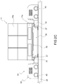
- the horizontal faces 28b act as supporting and sliding surfaces for a plurality of wheels 40 of a self-propelled apparatus 30 (illustrated in Fig. 2C ) for moving cargo units 11.
- the apparatus 30 comprises, in a non-limiting embodiment, a first main means or vehicle 32 (referred to herein below as “shuttle”, and illustrated in detail in Fig. 2A ), and a second auxiliary means or vehicle 33 (referred to herein below as “satellite”, and illustrated in detail in Fig. 2B ).
- the second means is able to be transported by the first means by accommodating in a special seat 33a obtained in a structure 33 of the shuttle 32.
- the seat 33a is defined in the longitudinal direction by two uprights 36, having vertical edges 33b.
- the uprights 36 act as rest surfaces for the cargo units 11.
- the cargo units 11 usually comprise a pallet 11a supporting a load 11b ( Fig. 3 ).
- the satellite 34 comprises a structure 42, a plurality of wheels 46, and means 35 for withdrawing or depositing the cargo unit 11.
- Cargo unit 11 is located in a shelving 13 that is arranged at a side of the main aisle 12.
- the means 35 comprise, according to an embodiment of the invention, a rest plate 35a that may be lifted by means of a pantograph mechanism 35b, or, optionally, by means of jacks or actuators of another kind.
- the shelving 13, as illustrated in the Figs. 1 and 3 is supported by a plurality of uprights 20 and ribs 20a, and it provides a plurality of secondary paths 16, arranged along a direction transversal or perpendicular with respect to the main aisle 12.
- the secondary paths 16 are defined, along all or part of the length thereof, each by two secondary side guides 18. These guides are preferably obtained with box- or inverted U-shaped metal section bars.
- Each secondary guide 18 provides a first vertical inner face 19b, facing toward the secondary path 16, a second vertical outer face 19c parallel to the first face, a horizontal connection face 19a between the first and the second faces, and a flat projection 19d, facing toward the secondary path 16, acting as a supporting and sliding surface for the wheels 46 of the satellite 34.
- Each secondary path 16 comprises one or more boxes 16b to accommodate the cargo units 11.
- the shelves 13 are provided on both longitudinal sides of the main aisle 12.
- multiple central aisles 12 may be provided, interspersed with the shelves 13.
- the shelves are generally multi-floor shelves, extending also vertically, in addition to longitudinally and transversally, i.e., comprising one or more mutually overlying floors 14.
- Each floor 14 provides a plurality of secondary paths 16, according to the forms described above.
- a respective main aisle 12 is flanked to each floor 14, thus determining an overlapping and a spacing of the central aisles 12 along the vertical axis z.
- multiple shuttles and/or satellites may operate on each of the central aisles 12.
- one of the two primary guides 24 suitably provides a data representation 26 on the inner face 28a, in this example, an optical representation in the form of a linear bar code.
- Said embodiment of the representation 26 is not to be construed as limiting as regards:
- one of the two secondary guides 18 suitably provides, on the inner face 19b, a data representation 22, in this example, an optical representation in the form of a linear bar code.
- a data representation 22 in this example, an optical representation in the form of a linear bar code.
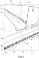
- Fig. 4 shows a detail of a preferred embodiment of the arrangement of the data representations 22, 26 on a primary guide 24 and a secondary guide 18.
- the data representations represent a separate plurality of alpha-numerical data, identifying a plurality of reference points or ranges 10.
- Each reference point or range 10 is associated with a point or a length of the primary or secondary paths, and it is univocally identified within the warehouse 9.
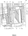
- Some points or lengths correspond to the positions of a box 16b for accommodating one or more cargo units 11 ( Fig. 5 ).
- a virtual mapping of all the reference points 10 provided in the warehouse is carried out. This virtual mapping is stored in a computing processing unit (not illustrated). According to a convenient embodiment, a single processing unit is provided for the entire warehouse 9. According to non-illustrated embodiments, the processing unit may be located on the shuttle 32 and/or the satellite 34.
- the processing unit When the withdrawal or deposition of a cargo unit 11 at a particular box 16b in the warehouse 9 is set, the processing unit identifies the reference point or range 10 corresponding to the selected box 16b.
- the distribution of the reference points or ranges 10 in the warehouse has not to necessarily follow a pre-ordered numerical sequence. Such a sequence may also be random, since the control of the shuttles and the satellites positioning occurs according to discrete points, and not according to (absolute or incremental) distances.
- the processing unit sends to the self-propelled apparatus 30 the instruction to reach the reference point or range 10 associated with the box 16b.
- the self-propelled apparatus 30 travels along the main aisle 12 until the vertical edges 33b of the seat 33a of the shuttle 32 overlap with the projections, with respect to a plane parallel to the plane identified by the vectors x and z, of the inner faces 19b of the two consecutive secondary guides 18 bounding the secondary path 16 of the shelving 13 in which the reference point 10 where the cargo unit 11 has to be withdrawn or deposited is located.
- the movement of the self-propelled apparatus 30 and the proper mutual positioning between the self-propelled apparatus 30 and the secondary path 16, containing the box 16b, are controlled by a sensor 38, mounted on board of the shuttle 32.
- the sensor 38 is a reading or detection device of the optical type.
- the shuttle 32 may also comprise multiple sensors 38.
- the sensor 38 is able to detect the exact location of the self-propelled apparatus 30 or the single shuttle 32 on the main path 12 by reading and decoding the reference points or ranges 10 represented by the bar code 26 on the primary guide 24.
- the satellite 34 lifts, by means of the plate 35a, the cargo unit 11, disengaging it from the shuttle 32.
- the satellite 34 moves along the secondary path 16, sliding on the projections 19d of the secondary guides 18, and transports the cargo unit along the secondary path 16 to reach the position corresponding to the box 16b identified by the reference point or range 10.
- the movement of the satellite 34 and the proper positioning of the satellite 34 at the box 16b are controlled by a sensor 48, mounted on board of the satellite 34.
- the sensor 48 is a reading or detection device of the optical type.
- the satellite 34 may also comprise multiple sensors 48.
- the sensor 48 is able to detect the exact location of the satellite 34 on the secondary path 16 by reading and decoding the reference points or ranges 10 represented by the bar code 22 on the secondary guide 18.
- the satellite 34 lowers the plate 35a, resting the pallet 11a of the unit 11 on the planar surfaces 19a of the guides 18.
- the satellite moves back along the secondary path 16 up to a threshold 16a of the secondary path 16.
- the satellite 34 disconnects from the shuttle 32 and moves along the secondary path 16, sliding on the projections 19d of the secondary guides 18, to reach the position corresponding to the box 16b identified by the reference point or range 10 associated with the box 16b.
- the satellite 34 lifts, by means of the plate 35a, the cargo unit 11, disengaging it from the guide 18, and moves back along the secondary path 16 up to a threshold 16a ( Fig. 4 ) of the secondary path 16, transporting the cargo unit 11 along the secondary path 16.
- the shuttle 32 While carrying out the operations performed by the satellite 34, the shuttle 32 is free to perform other operations, without necessarily having to wait for the return of the satellite.
- two or more shuttles 32 and/or two or more satellites 34 are provided in the warehouse; in theory, a shuttle 32 can discharge the satellite 34 at a first secondary path and, while the satellite performs its operations, the shuttle is free to withdraw a further satellite in a second secondary path other than the first one.
- the warehouse is provided with a loading and/or unloading station 60 for those cargo units 11 that have to be inserted or withdrawn from the warehouse ( Fig. 4 ).
- the loading and/or unloading station 60 is located at an end 12a of the main aisle 12, at the level of a floor P considered as the base surface of the entire warehouse.
- loading and/or unloading stations 60 are provided at two or more central aisles 12.
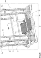
- the stations 60 may have sliding guides or conveyor belts 60a, receiving from or loading on the shuttle 32 the cargo units 11, either directly or, as illustrated in the Figs. 5 and 6 , via intermediate stations 54, which are provided with sliding guides or conveyor belts 54a.
- the shuttle 32 and the intermediate stations 54 may be accommodated in a lifting platform 52, supported by uprights 50 of a lifting structure 49.
- the lifting structure 49 allows to vertically move the self-propelled apparatus 30 or only the shuttle 32, so that the apparatus or the shuttle can pass on the different central aisles corresponding to each floor 14 of the shelving 13.
- one of the uprights 50 provides a third location data representation 62 located on an inner face 50a of the upright.
- a third sensor 64 is mounted on the lifting platform 52.
- the third sensor 64 is configured to read the data of the third location data representation 62.
- the data representation 62 is a representation of the optical type, in the form of a linear bar code.
- the lifting platform 52 may also comprise multiple sensors 64.
- the sensor 64 is able to detect the exact vertical height (i.e., along the vector z) where the lifting platform 52 is located with respect to the upright 50.
- the sensor 64 detects such position by reading and decoding the reference points or ranges 10 represented by the bar code 62 on the upright 50.
- the data representations 22, 26, 62 provide a location datum along the transversal (y), longitudinal (x), and vertical (z) directions, respectively. These available data allow to obtain a tridimensional mapping of the warehouse 9.
- the lifting structure 49 can move independently of the presence of the apparatus 30, of the shuttle 32 or one or more cargo units 11 on the intermediate stations 54, resulting in a further optimization of the operative times.
- a possible initial step of the storing method is to put a cargo unit on the loading station 60; the lifting platform 52 of the lifting structure 49 is lowered to the floor P plane, i.e., forming a contiguity between the sliding guides 60a of the loading/unloading stations 60, the sliding guides 54a of the intermediate stations 54 and/or chain rolls 37 located on the uprights 36 of the structure 33 of the shuttle 32 ( Figs. 2A , 5 , and 6 ).
- the cargo unit passes to an intermediate station 54, from which the load is transferred to the shuttle, by means of telescopic forks or chain rolls 37 of the shuttle 32.
- the configuration where the shuttle 32 comprises the rolls 37 is a preferred one, since it allows the shuttle loading and/or unloading the cargo unit independently of the presence on board of the satellite, i.e., housed in the seat 33a.
- the shuttle 32 passes the load to the intermediate station 54, from which the load is further transferred to the unloading station 60, where it is withdrawn.
- such sensors are preferably of the optical type.
- the particular technology of the sensor will be able to vary according to the needs.
- optical readers with light sources associated with photodiodes, laser light sources, LED bar light sources, CCD (Charged Coupled Device) sensors, image reading systems of the photo camera type, readers of the "Large field-of-view” type using high resolution photo cameras able to simultaneously capture information from a multiplicity of bar codes, etc. may be used.
- the sensors 38, 48, 64 can be of a different type, in accordance with the type of data representation, for example, magnetic sensors.
Landscapes
- Engineering & Computer Science (AREA)
- Mechanical Engineering (AREA)
- Warehouses Or Storage Devices (AREA)
- Devices That Are Associated With Refrigeration Equipment (AREA)
Applications Claiming Priority (2)
| Application Number | Priority Date | Filing Date | Title |
|---|---|---|---|
| IT000628A ITTO20130628A1 (it) | 2013-07-24 | 2013-07-24 | Magazzino automatizzato |
| PCT/IB2014/060649 WO2015011575A1 (en) | 2013-07-24 | 2014-04-11 | An automated warehouse |
Publications (2)
| Publication Number | Publication Date |
|---|---|
| EP2994400A1 EP2994400A1 (en) | 2016-03-16 |
| EP2994400B1 true EP2994400B1 (en) | 2017-01-04 |
Family
ID=49118724
Family Applications (1)
| Application Number | Title | Priority Date | Filing Date |
|---|---|---|---|
| EP14728293.3A Active EP2994400B1 (en) | 2013-07-24 | 2014-04-11 | An automated warehouse |
Country Status (9)
| Country | Link |
|---|---|
| US (1) | US9630774B2 (it) |
| EP (1) | EP2994400B1 (it) |
| JP (2) | JP2016525053A (it) |
| KR (2) | KR20210000708U (it) |
| CN (1) | CN105612112B (it) |
| ES (1) | ES2621308T3 (it) |
| IT (1) | ITTO20130628A1 (it) |
| PT (1) | PT2994400T (it) |
| WO (1) | WO2015011575A1 (it) |
Cited By (1)
| Publication number | Priority date | Publication date | Assignee | Title |
|---|---|---|---|---|
| US12570471B2 (en) | 2022-04-29 | 2026-03-10 | Finmatec Oy Ab | Automated bin storage |
Families Citing this family (16)
| Publication number | Priority date | Publication date | Assignee | Title |
|---|---|---|---|---|
| US9792577B2 (en) * | 2012-10-04 | 2017-10-17 | Amazon Technologies, Inc. | Filling an order at an inventory pier |
| PL3283712T3 (pl) * | 2015-04-15 | 2019-08-30 | Ocado Innovation Limited | Robotyczne urządzenie parkingowe i sposób obsługi |
| US10207867B2 (en) * | 2015-07-01 | 2019-02-19 | Swisslog Logistics, Inc. | Automated pallet storage and retrieval system |
| CN107840101A (zh) * | 2016-09-19 | 2018-03-27 | 珠海迈超智能装备有限公司 | 一种带升降输送机构的智能移动工具 |
| MX2020013280A (es) | 2018-06-08 | 2021-02-22 | Attabotics Inc | Sistemas mejorados de almacenamiento y recuperacion. |
| JP7143145B2 (ja) * | 2018-08-09 | 2022-09-28 | 住友重機械搬送システム株式会社 | 自動倉庫システム |
| CN110417878B (zh) * | 2018-12-10 | 2022-05-17 | 李耸 | 云服务器控制下的移动通信仓库 |
| DE102019207645A1 (de) * | 2019-05-24 | 2020-11-26 | Gebhardt Fördertechnik GmbH | Förderfahrzeug für ein Regalsystem, Verfahren zum Betrieb eines solchen Förderfahrzeugs und System aus Förderfahrzeug und Regalsystem oder Regallager |
| USD898092S1 (en) * | 2019-06-03 | 2020-10-06 | Storage Management Sysem (Pty) Ltd. | Bogie for a warehousing shuttle |
| ES3064544T3 (en) | 2019-06-11 | 2026-04-27 | Lafayette Systems Canada ULC | Manufacturing system with an interconnected storage structure and manufacturing cells sharing a common robotic fleet |
| IT201900012081A1 (it) * | 2019-07-17 | 2021-01-17 | Eurofork S P A | Magazzino automatizzato con sistema di accesso sicuro |
| IT202000009502A1 (it) * | 2020-04-30 | 2021-10-30 | System Logistics S P A | Elevatore per impianti di immagazzinamento automatici |
| JP2022152110A (ja) * | 2021-03-29 | 2022-10-12 | 住友重機械搬送システム株式会社 | 自動倉庫システム |
| GB202300945D0 (en) * | 2023-01-23 | 2023-03-08 | Thistle Storage Equipment Ltd | Lifting device, transport apparatus and storage system |
| IT202300005928A1 (it) * | 2023-03-28 | 2024-09-28 | Eurofork S P A | Magazzino automatizzato con veicolo four-way |
| US12037196B1 (en) * | 2023-08-09 | 2024-07-16 | 1Mrobotics Ltd. | Warehouses having multiple storage units connected in series |
Family Cites Families (55)
| Publication number | Priority date | Publication date | Assignee | Title |
|---|---|---|---|---|
| US2763381A (en) * | 1956-09-18 | bowles | ||
| US1830740A (en) * | 1929-03-19 | 1931-11-03 | Leech Carrier Corp | Freight handling device |
| US1824201A (en) * | 1930-01-27 | 1931-09-22 | Eisenberg Isidor | Lift-truck |
| US1903274A (en) * | 1930-09-10 | 1933-03-28 | Archie S Watson | Garage handling mechanism |
| US2633809A (en) * | 1950-08-03 | 1953-04-07 | Jr Joseph J Robinson | Transfer mechanism for automobile parking garages |
| US3531705A (en) * | 1965-11-05 | 1970-09-29 | Eaton Yale & Towne | Method and apparatus for automatic load transfer |
| US3389814A (en) * | 1966-06-07 | 1968-06-25 | Triax Co | Load responsive control means for a material handling apparatus |
| DE1556636A1 (de) * | 1968-02-22 | 1970-10-22 | Krupp Gmbh | Container-Umschlaganlage |
| US3543952A (en) * | 1968-03-29 | 1970-12-01 | Kaiser Ind Corp | Container handling and storage system |
| JPS5315262B2 (it) * | 1972-04-19 | 1978-05-23 | ||
| US3927773A (en) * | 1972-06-19 | 1975-12-23 | Thomas John Robert Bright | Load storage system and apparatus therefor |
| US4007843A (en) * | 1972-07-17 | 1977-02-15 | Rapistan, Incorporated | Multi-aisle warehouse system with mobile lift having control means for an article transfer vehicle |
| JPS5034981U (it) * | 1973-07-27 | 1975-04-14 | ||
| AT326047B (de) * | 1973-09-06 | 1975-11-25 | Haldimann Consultants | Durchlaufregallager-anlage |
| JPS5337622B2 (it) * | 1973-12-05 | 1978-10-11 | ||
| US3850316A (en) * | 1974-01-28 | 1974-11-26 | Columbia Machine | Apparatus for loading and unloading vertically stacked racks |
| US4085849A (en) * | 1976-02-10 | 1978-04-25 | Richard Jablin | Machinery locating device |
| CA1046009A (en) * | 1976-08-16 | 1979-01-09 | Du Pont Of Canada Limited | System for lagging yarn on yarn buggies |
| US4191499A (en) * | 1978-07-25 | 1980-03-04 | Futerized Systems, Inc. | Live storage system |
| US4265583A (en) * | 1978-08-15 | 1981-05-05 | General Electric Company | Lift truck for facilitating insertion and removal of horizontal draw-out switchgear unit |
| US4299496A (en) * | 1978-11-06 | 1981-11-10 | Interlake, Inc. | Load proximity detection techniques |
| DE2925469C2 (de) * | 1979-06-23 | 1982-07-08 | Stolzer-Lagertechnik GmbH, 7590 Achern | Einrichtung zur Lagerung von stangenförmigem Material und zur selbsttätigen, programmgesteuerten Versorgung einer Trennmaschine mit diesem Material |
| US4541766A (en) * | 1982-08-09 | 1985-09-17 | Karl Dahl | Device for handling packs of elongated articles, especially lumber packs |
| US4639187A (en) * | 1984-07-16 | 1987-01-27 | Tsubakimoto Chain Co. | Automatic storing equipment |
| US4718810A (en) * | 1985-12-06 | 1988-01-12 | Lico, Inc. | High speed transporter for multiple station production line |
| JPS62168205A (ja) * | 1986-01-21 | 1987-07-24 | Nec Corp | 無人搬送車 |
| US4729467A (en) * | 1986-05-20 | 1988-03-08 | Mid-West Conveyor Company, Inc. | Transport assembly for use with storage conveyor, and combination |
| DE3877047D1 (de) * | 1987-05-06 | 1993-02-11 | Doerries Scharmann Gmbh | Flexible fertigungseinrichtung mit mehreren parallel im abstand nebeneinander angeordneten bearbeitungsmaschinen. |
| EP0390813B1 (en) * | 1987-11-12 | 1993-11-03 | Kone Oy | Method and store for storing paper rolls |
| US5054986A (en) * | 1988-09-08 | 1991-10-08 | Tsubakimoto Chain Co. | Storage and conveyance of heavy articles |
| KR910004795B1 (ko) * | 1988-12-27 | 1991-07-13 | 정수철 | 자체 입고수단을 갖는 입체형 주차장치 |
| DE3920405C1 (it) * | 1989-06-22 | 1990-03-29 | Goldschmidt, Sol, Zuerich, Ch | |
| JPH0412601A (ja) * | 1990-04-27 | 1992-01-17 | Mitsubishi Heavy Ind Ltd | 搬送台車等の絶対番地検出方法 |
| US5226782A (en) * | 1990-05-07 | 1993-07-13 | Stanley-Vidmar, Inc. | Automatic storage and retrieval system |
| US5379229A (en) * | 1992-06-18 | 1995-01-03 | Communications Test Design, Inc. | Automated storage and retrieval system |
| DE19626966A1 (de) * | 1996-07-04 | 1998-01-08 | Cegelec Aeg Anlagen Und Automa | Spurgeführtes Transportsystem mit Transportfahrzeugen |
| US6652213B1 (en) * | 2000-09-08 | 2003-11-25 | California Natural Products | Automated warehousing system and method |
| DE10136354B4 (de) * | 2001-07-26 | 2010-06-17 | Knapp Ag | Verfahren und Anlage zum Kommissionieren mit einem Behälterregal und zugeordnetem Regalbediengerät |
| US7991505B2 (en) * | 2003-08-29 | 2011-08-02 | Casepick Systems, Llc | Materials-handling system using autonomous transfer and transport vehicles |
| US7591630B2 (en) * | 2003-08-29 | 2009-09-22 | Casepick Systems, Llc | Materials-handling system using autonomous transfer and transport vehicles |
| FR2859652B1 (fr) * | 2003-09-17 | 2005-10-21 | Solystic | Machine de tri postal comprenant une structure de transfert de bacs |
| JP4214533B2 (ja) * | 2006-08-10 | 2009-01-28 | 村田機械株式会社 | 移動体システム |
| JP4756367B2 (ja) * | 2006-08-17 | 2011-08-24 | 株式会社ダイフク | 物品収納設備 |
| FR2940149B1 (fr) * | 2008-12-23 | 2010-12-03 | Solystic | Machine de tri postal avec chariot pour la manipulation des envois postaux |
| US8740538B2 (en) * | 2009-04-10 | 2014-06-03 | Symbotic, LLC | Storage and retrieval system |
| US9321591B2 (en) * | 2009-04-10 | 2016-04-26 | Symbotic, LLC | Autonomous transports for storage and retrieval systems |
| EP2544971B1 (en) * | 2010-03-12 | 2020-12-16 | Symbotic LLC | Replenishment and order fulfillment system |
| US8694152B2 (en) * | 2010-12-15 | 2014-04-08 | Symbotic, LLC | Maintenance access zones for storage and retrieval systems |
| US8696010B2 (en) * | 2010-12-15 | 2014-04-15 | Symbotic, LLC | Suspension system for autonomous transports |
| US8965619B2 (en) * | 2010-12-15 | 2015-02-24 | Symbotic, LLC | Bot having high speed stability |
| US9187244B2 (en) * | 2010-12-15 | 2015-11-17 | Symbotic, LLC | BOT payload alignment and sensing |
| US8998554B2 (en) * | 2010-12-15 | 2015-04-07 | Symbotic Llc | Multilevel vertical conveyor platform guides |
| ITBG20110011U1 (it) * | 2011-03-21 | 2012-09-22 | Automha S R L | Impianto automatico di stoccaggio. |
| US9334114B2 (en) * | 2011-11-20 | 2016-05-10 | Illinois Tool Works Inc. | Storage system and methods |
| CN202864190U (zh) * | 2012-09-27 | 2013-04-10 | 余玉刚 | 仓储系统 |
-
2013
- 2013-07-24 IT IT000628A patent/ITTO20130628A1/it unknown
-
2014
- 2014-04-11 CN CN201480001792.2A patent/CN105612112B/zh active Active
- 2014-04-11 PT PT147282933T patent/PT2994400T/pt unknown
- 2014-04-11 ES ES14728293.3T patent/ES2621308T3/es active Active
- 2014-04-11 KR KR2020217000018U patent/KR20210000708U/ko not_active Ceased
- 2014-04-11 WO PCT/IB2014/060649 patent/WO2015011575A1/en not_active Ceased
- 2014-04-11 JP JP2016528616A patent/JP2016525053A/ja active Pending
- 2014-04-11 US US14/901,087 patent/US9630774B2/en active Active
- 2014-04-11 EP EP14728293.3A patent/EP2994400B1/en active Active
- 2014-04-11 KR KR1020157036332A patent/KR20160034854A/ko not_active Withdrawn
-
2019
- 2019-03-27 JP JP2019001084U patent/JP3222407U/ja not_active Expired - Lifetime
Non-Patent Citations (1)
| Title |
|---|
| None * |
Cited By (1)
| Publication number | Priority date | Publication date | Assignee | Title |
|---|---|---|---|---|
| US12570471B2 (en) | 2022-04-29 | 2026-03-10 | Finmatec Oy Ab | Automated bin storage |
Also Published As
| Publication number | Publication date |
|---|---|
| US20160137418A1 (en) | 2016-05-19 |
| PT2994400T (pt) | 2017-03-23 |
| KR20210000708U (ko) | 2021-03-29 |
| CN105612112B (zh) | 2017-06-23 |
| ES2621308T3 (es) | 2017-07-03 |
| JP3222407U (ja) | 2019-08-01 |
| WO2015011575A1 (en) | 2015-01-29 |
| ITTO20130628A1 (it) | 2015-01-25 |
| JP2016525053A (ja) | 2016-08-22 |
| US9630774B2 (en) | 2017-04-25 |
| CN105612112A (zh) | 2016-05-25 |
| KR20160034854A (ko) | 2016-03-30 |
| EP2994400A1 (en) | 2016-03-16 |
Similar Documents
| Publication | Publication Date | Title |
|---|---|---|
| EP2994400B1 (en) | An automated warehouse | |
| KR102437649B1 (ko) | 운반 디바이스 위치 결정 장치 및 방법 | |
| CN108861289B (zh) | 仓库及订单完成系统 | |
| KR100418328B1 (ko) | 화물보관시스템의 무팔레트 적재구조 | |
| JP2022514979A (ja) | 搬送ロボット、入庫・物流システム及び品目搬送方法 | |
| KR20220044830A (ko) | 재고 관리 시스템에 사용하기 위한 자율 주행 운반차 | |
| CN113353518A (zh) | 用于检查仓库的系统 | |
| JP5413413B2 (ja) | 自動倉庫 | |
| JPWO2012132569A1 (ja) | 自動倉庫 | |
| KR102280791B1 (ko) | 저상형 자동 창고 시스템 | |
| KR20200093283A (ko) | 스태커 크레인을 이용한 랙 위치 정보 측정 방법 | |
| JP2019001655A (ja) | 自動倉庫システム | |
| JP2005138956A (ja) | 自動倉庫における入庫方法 | |
| KR102412923B1 (ko) | 검사 장치 | |
| JP2000238904A (ja) | スタッカクレーン | |
| JP2012153470A (ja) | 自動倉庫 | |
| CN218490556U (zh) | 仓库运输系统 | |
| JP4409252B2 (ja) | 自動倉庫における入庫方法 | |
| CN117262567A (zh) | 一种基于计算机视觉的立库盘点系统和盘点方法 | |
| US12569978B1 (en) | Autonomous mobile machine, method for controlling autonomous mobile machine, and controller | |
| US12572157B1 (en) | Autonomous mobile machine, method for controlling autonomous mobile machine, and controller | |
| CN114590507A (zh) | 一种定位系统和定位方法 | |
| JP7520551B2 (ja) | 自動倉庫システム、自動倉庫システムの制御方法及び制御プログラム | |
| CN219990175U (zh) | 货架及仓储系统 | |
| JP7443910B2 (ja) | 自動倉庫 |
Legal Events
| Date | Code | Title | Description |
|---|---|---|---|
| PUAI | Public reference made under article 153(3) epc to a published international application that has entered the european phase |
Free format text: ORIGINAL CODE: 0009012 |
|
| 17P | Request for examination filed |
Effective date: 20151211 |
|
| AK | Designated contracting states |
Kind code of ref document: A1 Designated state(s): AL AT BE BG CH CY CZ DE DK EE ES FI FR GB GR HR HU IE IS IT LI LT LU LV MC MK MT NL NO PL PT RO RS SE SI SK SM TR |
|
| AX | Request for extension of the european patent |
Extension state: BA ME |
|
| DAX | Request for extension of the european patent (deleted) | ||
| GRAP | Despatch of communication of intention to grant a patent |
Free format text: ORIGINAL CODE: EPIDOSNIGR1 |
|
| GRAS | Grant fee paid |
Free format text: ORIGINAL CODE: EPIDOSNIGR3 |
|
| GRAA | (expected) grant |
Free format text: ORIGINAL CODE: 0009210 |
|
| INTG | Intention to grant announced |
Effective date: 20161109 |
|
| AK | Designated contracting states |
Kind code of ref document: B1 Designated state(s): AL AT BE BG CH CY CZ DE DK EE ES FI FR GB GR HR HU IE IS IT LI LT LU LV MC MK MT NL NO PL PT RO RS SE SI SK SM TR |
|
| REG | Reference to a national code |
Ref country code: GB Ref legal event code: FG4D |
|
| REG | Reference to a national code |
Ref country code: CH Ref legal event code: EP |
|
| REG | Reference to a national code |
Ref country code: AT Ref legal event code: REF Ref document number: 859001 Country of ref document: AT Kind code of ref document: T Effective date: 20170115 |
|
| REG | Reference to a national code |
Ref country code: IE Ref legal event code: FG4D |
|
| REG | Reference to a national code |
Ref country code: DE Ref legal event code: R096 Ref document number: 602014006078 Country of ref document: DE |
|
| REG | Reference to a national code |
Ref country code: PT Ref legal event code: SC4A Ref document number: 2994400 Country of ref document: PT Date of ref document: 20170323 Kind code of ref document: T Free format text: AVAILABILITY OF NATIONAL TRANSLATION Effective date: 20170316 |
|
| REG | Reference to a national code |
Ref country code: RO Ref legal event code: EPE |
|
| REG | Reference to a national code |
Ref country code: CH Ref legal event code: NV Representative=s name: JACOBACCI AND PARTNERS SA, CH |
|
| REG | Reference to a national code |
Ref country code: FR Ref legal event code: PLFP Year of fee payment: 4 |
|
| REG | Reference to a national code |
Ref country code: LT Ref legal event code: MG4D Ref country code: NL Ref legal event code: MP Effective date: 20170104 |
|
| PG25 | Lapsed in a contracting state [announced via postgrant information from national office to epo] |
Ref country code: NL Free format text: LAPSE BECAUSE OF FAILURE TO SUBMIT A TRANSLATION OF THE DESCRIPTION OR TO PAY THE FEE WITHIN THE PRESCRIBED TIME-LIMIT Effective date: 20170104 |
|
| REG | Reference to a national code |
Ref country code: ES Ref legal event code: FG2A Ref document number: 2621308 Country of ref document: ES Kind code of ref document: T3 Effective date: 20170703 |
|
| PG25 | Lapsed in a contracting state [announced via postgrant information from national office to epo] |
Ref country code: FI Free format text: LAPSE BECAUSE OF FAILURE TO SUBMIT A TRANSLATION OF THE DESCRIPTION OR TO PAY THE FEE WITHIN THE PRESCRIBED TIME-LIMIT Effective date: 20170104 Ref country code: LT Free format text: LAPSE BECAUSE OF FAILURE TO SUBMIT A TRANSLATION OF THE DESCRIPTION OR TO PAY THE FEE WITHIN THE PRESCRIBED TIME-LIMIT Effective date: 20170104 Ref country code: HR Free format text: LAPSE BECAUSE OF FAILURE TO SUBMIT A TRANSLATION OF THE DESCRIPTION OR TO PAY THE FEE WITHIN THE PRESCRIBED TIME-LIMIT Effective date: 20170104 Ref country code: GR Free format text: LAPSE BECAUSE OF FAILURE TO SUBMIT A TRANSLATION OF THE DESCRIPTION OR TO PAY THE FEE WITHIN THE PRESCRIBED TIME-LIMIT Effective date: 20170405 Ref country code: NO Free format text: LAPSE BECAUSE OF FAILURE TO SUBMIT A TRANSLATION OF THE DESCRIPTION OR TO PAY THE FEE WITHIN THE PRESCRIBED TIME-LIMIT Effective date: 20170404 Ref country code: IS Free format text: LAPSE BECAUSE OF FAILURE TO SUBMIT A TRANSLATION OF THE DESCRIPTION OR TO PAY THE FEE WITHIN THE PRESCRIBED TIME-LIMIT Effective date: 20170504 |
|
| PGFP | Annual fee paid to national office [announced via postgrant information from national office to epo] |
Ref country code: IE Payment date: 20170421 Year of fee payment: 4 |
|
| PG25 | Lapsed in a contracting state [announced via postgrant information from national office to epo] |
Ref country code: SE Free format text: LAPSE BECAUSE OF FAILURE TO SUBMIT A TRANSLATION OF THE DESCRIPTION OR TO PAY THE FEE WITHIN THE PRESCRIBED TIME-LIMIT Effective date: 20170104 Ref country code: BG Free format text: LAPSE BECAUSE OF FAILURE TO SUBMIT A TRANSLATION OF THE DESCRIPTION OR TO PAY THE FEE WITHIN THE PRESCRIBED TIME-LIMIT Effective date: 20170404 Ref country code: RS Free format text: LAPSE BECAUSE OF FAILURE TO SUBMIT A TRANSLATION OF THE DESCRIPTION OR TO PAY THE FEE WITHIN THE PRESCRIBED TIME-LIMIT Effective date: 20170104 Ref country code: LV Free format text: LAPSE BECAUSE OF FAILURE TO SUBMIT A TRANSLATION OF THE DESCRIPTION OR TO PAY THE FEE WITHIN THE PRESCRIBED TIME-LIMIT Effective date: 20170104 Ref country code: PL Free format text: LAPSE BECAUSE OF FAILURE TO SUBMIT A TRANSLATION OF THE DESCRIPTION OR TO PAY THE FEE WITHIN THE PRESCRIBED TIME-LIMIT Effective date: 20170104 |
|
| REG | Reference to a national code |
Ref country code: DE Ref legal event code: R097 Ref document number: 602014006078 Country of ref document: DE |
|
| PG25 | Lapsed in a contracting state [announced via postgrant information from national office to epo] |
Ref country code: SK Free format text: LAPSE BECAUSE OF FAILURE TO SUBMIT A TRANSLATION OF THE DESCRIPTION OR TO PAY THE FEE WITHIN THE PRESCRIBED TIME-LIMIT Effective date: 20170104 Ref country code: CZ Free format text: LAPSE BECAUSE OF FAILURE TO SUBMIT A TRANSLATION OF THE DESCRIPTION OR TO PAY THE FEE WITHIN THE PRESCRIBED TIME-LIMIT Effective date: 20170104 Ref country code: EE Free format text: LAPSE BECAUSE OF FAILURE TO SUBMIT A TRANSLATION OF THE DESCRIPTION OR TO PAY THE FEE WITHIN THE PRESCRIBED TIME-LIMIT Effective date: 20170104 |
|
| PLBE | No opposition filed within time limit |
Free format text: ORIGINAL CODE: 0009261 |
|
| STAA | Information on the status of an ep patent application or granted ep patent |
Free format text: STATUS: NO OPPOSITION FILED WITHIN TIME LIMIT |
|
| PG25 | Lapsed in a contracting state [announced via postgrant information from national office to epo] |
Ref country code: DK Free format text: LAPSE BECAUSE OF FAILURE TO SUBMIT A TRANSLATION OF THE DESCRIPTION OR TO PAY THE FEE WITHIN THE PRESCRIBED TIME-LIMIT Effective date: 20170104 Ref country code: SM Free format text: LAPSE BECAUSE OF FAILURE TO SUBMIT A TRANSLATION OF THE DESCRIPTION OR TO PAY THE FEE WITHIN THE PRESCRIBED TIME-LIMIT Effective date: 20170104 |
|
| PG25 | Lapsed in a contracting state [announced via postgrant information from national office to epo] |
Ref country code: MC Free format text: LAPSE BECAUSE OF FAILURE TO SUBMIT A TRANSLATION OF THE DESCRIPTION OR TO PAY THE FEE WITHIN THE PRESCRIBED TIME-LIMIT Effective date: 20170104 |
|
| PG25 | Lapsed in a contracting state [announced via postgrant information from national office to epo] |
Ref country code: LU Free format text: LAPSE BECAUSE OF NON-PAYMENT OF DUE FEES Effective date: 20170411 Ref country code: SI Free format text: LAPSE BECAUSE OF FAILURE TO SUBMIT A TRANSLATION OF THE DESCRIPTION OR TO PAY THE FEE WITHIN THE PRESCRIBED TIME-LIMIT Effective date: 20170104 |
|
| REG | Reference to a national code |
Ref country code: BE Ref legal event code: MM Effective date: 20170430 |
|
| REG | Reference to a national code |
Ref country code: FR Ref legal event code: PLFP Year of fee payment: 5 |
|
| PG25 | Lapsed in a contracting state [announced via postgrant information from national office to epo] |
Ref country code: BE Free format text: LAPSE BECAUSE OF NON-PAYMENT OF DUE FEES Effective date: 20170430 |
|
| PG25 | Lapsed in a contracting state [announced via postgrant information from national office to epo] |
Ref country code: MT Free format text: LAPSE BECAUSE OF NON-PAYMENT OF DUE FEES Effective date: 20170411 |
|
| REG | Reference to a national code |
Ref country code: IE Ref legal event code: MM4A |
|
| PG25 | Lapsed in a contracting state [announced via postgrant information from national office to epo] |
Ref country code: IE Free format text: LAPSE BECAUSE OF NON-PAYMENT OF DUE FEES Effective date: 20180411 |
|
| PG25 | Lapsed in a contracting state [announced via postgrant information from national office to epo] |
Ref country code: HU Free format text: LAPSE BECAUSE OF FAILURE TO SUBMIT A TRANSLATION OF THE DESCRIPTION OR TO PAY THE FEE WITHIN THE PRESCRIBED TIME-LIMIT; INVALID AB INITIO Effective date: 20140411 |
|
| REG | Reference to a national code |
Ref country code: AT Ref legal event code: UEP Ref document number: 859001 Country of ref document: AT Kind code of ref document: T Effective date: 20170104 |
|
| PG25 | Lapsed in a contracting state [announced via postgrant information from national office to epo] |
Ref country code: CY Free format text: LAPSE BECAUSE OF FAILURE TO SUBMIT A TRANSLATION OF THE DESCRIPTION OR TO PAY THE FEE WITHIN THE PRESCRIBED TIME-LIMIT Effective date: 20170104 |
|
| PG25 | Lapsed in a contracting state [announced via postgrant information from national office to epo] |
Ref country code: MK Free format text: LAPSE BECAUSE OF FAILURE TO SUBMIT A TRANSLATION OF THE DESCRIPTION OR TO PAY THE FEE WITHIN THE PRESCRIBED TIME-LIMIT Effective date: 20170104 |
|
| PG25 | Lapsed in a contracting state [announced via postgrant information from national office to epo] |
Ref country code: AL Free format text: LAPSE BECAUSE OF FAILURE TO SUBMIT A TRANSLATION OF THE DESCRIPTION OR TO PAY THE FEE WITHIN THE PRESCRIBED TIME-LIMIT Effective date: 20170104 |
|
| PGFP | Annual fee paid to national office [announced via postgrant information from national office to epo] |
Ref country code: CH Payment date: 20220421 Year of fee payment: 9 |
|
| REG | Reference to a national code |
Ref country code: CH Ref legal event code: PL |
|
| PG25 | Lapsed in a contracting state [announced via postgrant information from national office to epo] |
Ref country code: LI Free format text: LAPSE BECAUSE OF NON-PAYMENT OF DUE FEES Effective date: 20230430 Ref country code: CH Free format text: LAPSE BECAUSE OF NON-PAYMENT OF DUE FEES Effective date: 20230430 |
|
| PGFP | Annual fee paid to national office [announced via postgrant information from national office to epo] |
Ref country code: AT Payment date: 20240417 Year of fee payment: 11 |
|
| PGFP | Annual fee paid to national office [announced via postgrant information from national office to epo] |
Ref country code: RO Payment date: 20240401 Year of fee payment: 11 |
|
| PGFP | Annual fee paid to national office [announced via postgrant information from national office to epo] |
Ref country code: PT Payment date: 20240328 Year of fee payment: 11 |
|
| PGFP | Annual fee paid to national office [announced via postgrant information from national office to epo] |
Ref country code: TR Payment date: 20240408 Year of fee payment: 11 |
|
| PGFP | Annual fee paid to national office [announced via postgrant information from national office to epo] |
Ref country code: DE Payment date: 20250424 Year of fee payment: 12 |
|
| PGFP | Annual fee paid to national office [announced via postgrant information from national office to epo] |
Ref country code: ES Payment date: 20250505 Year of fee payment: 12 |
|
| PG25 | Lapsed in a contracting state [announced via postgrant information from national office to epo] |
Ref country code: PT Free format text: LAPSE BECAUSE OF NON-PAYMENT OF DUE FEES Effective date: 20251013 |
|
| REG | Reference to a national code |
Ref country code: AT Ref legal event code: MM01 Ref document number: 859001 Country of ref document: AT Kind code of ref document: T Effective date: 20250411 |
|
| PG25 | Lapsed in a contracting state [announced via postgrant information from national office to epo] |
Ref country code: AT Free format text: LAPSE BECAUSE OF NON-PAYMENT OF DUE FEES Effective date: 20250411 |
|
| PG25 | Lapsed in a contracting state [announced via postgrant information from national office to epo] |
Ref country code: RO Free format text: LAPSE BECAUSE OF NON-PAYMENT OF DUE FEES Effective date: 20250411 |
|
| PGFP | Annual fee paid to national office [announced via postgrant information from national office to epo] |
Ref country code: GB Payment date: 20260312 Year of fee payment: 13 |
|
| PGFP | Annual fee paid to national office [announced via postgrant information from national office to epo] |
Ref country code: IT Payment date: 20260306 Year of fee payment: 13 |
|
| PGFP | Annual fee paid to national office [announced via postgrant information from national office to epo] |
Ref country code: FR Payment date: 20260331 Year of fee payment: 13 |