EP2993333A1 - Antriebskraftsteuerungssystem und Sattelfahrzeug - Google Patents
Antriebskraftsteuerungssystem und Sattelfahrzeug Download PDFInfo
- Publication number
- EP2993333A1 EP2993333A1 EP14196399.1A EP14196399A EP2993333A1 EP 2993333 A1 EP2993333 A1 EP 2993333A1 EP 14196399 A EP14196399 A EP 14196399A EP 2993333 A1 EP2993333 A1 EP 2993333A1
- Authority
- EP
- European Patent Office
- Prior art keywords
- bank angle
- driving force
- angle
- relative
- absolute
- Prior art date
- Legal status (The legal status is an assumption and is not a legal conclusion. Google has not performed a legal analysis and makes no representation as to the accuracy of the status listed.)
- Granted
Links
Images





Classifications
-
- B—PERFORMING OPERATIONS; TRANSPORTING
- B60—VEHICLES IN GENERAL
- B60K—ARRANGEMENT OR MOUNTING OF PROPULSION UNITS OR OF TRANSMISSIONS IN VEHICLES; ARRANGEMENT OR MOUNTING OF PLURAL DIVERSE PRIME-MOVERS IN VEHICLES; AUXILIARY DRIVES FOR VEHICLES; INSTRUMENTATION OR DASHBOARDS FOR VEHICLES; ARRANGEMENTS IN CONNECTION WITH COOLING, AIR INTAKE, GAS EXHAUST OR FUEL SUPPLY OF PROPULSION UNITS IN VEHICLES
- B60K31/00—Vehicle fittings, acting on a single sub-unit only, for automatically controlling vehicle speed, i.e. preventing speed from exceeding an arbitrarily established velocity or maintaining speed at a particular velocity, as selected by the vehicle operator
- B60K31/0066—Vehicle fittings, acting on a single sub-unit only, for automatically controlling vehicle speed, i.e. preventing speed from exceeding an arbitrarily established velocity or maintaining speed at a particular velocity, as selected by the vehicle operator responsive to vehicle path curvature
-
- B—PERFORMING OPERATIONS; TRANSPORTING
- B60—VEHICLES IN GENERAL
- B60K—ARRANGEMENT OR MOUNTING OF PROPULSION UNITS OR OF TRANSMISSIONS IN VEHICLES; ARRANGEMENT OR MOUNTING OF PLURAL DIVERSE PRIME-MOVERS IN VEHICLES; AUXILIARY DRIVES FOR VEHICLES; INSTRUMENTATION OR DASHBOARDS FOR VEHICLES; ARRANGEMENTS IN CONNECTION WITH COOLING, AIR INTAKE, GAS EXHAUST OR FUEL SUPPLY OF PROPULSION UNITS IN VEHICLES
- B60K31/00—Vehicle fittings, acting on a single sub-unit only, for automatically controlling vehicle speed, i.e. preventing speed from exceeding an arbitrarily established velocity or maintaining speed at a particular velocity, as selected by the vehicle operator
- B60K31/12—Vehicle fittings, acting on a single sub-unit only, for automatically controlling vehicle speed, i.e. preventing speed from exceeding an arbitrarily established velocity or maintaining speed at a particular velocity, as selected by the vehicle operator including a device responsive to centrifugal force
-
- B—PERFORMING OPERATIONS; TRANSPORTING
- B60—VEHICLES IN GENERAL
- B60W—CONJOINT CONTROL OF VEHICLE SUB-UNITS OF DIFFERENT TYPE OR DIFFERENT FUNCTION; CONTROL SYSTEMS SPECIALLY ADAPTED FOR HYBRID VEHICLES; ROAD VEHICLE DRIVE CONTROL SYSTEMS FOR PURPOSES NOT RELATED TO THE CONTROL OF A PARTICULAR SUB-UNIT
- B60W30/00—Purposes of road vehicle drive control systems not related to the control of a particular sub-unit, e.g. of systems using conjoint control of vehicle sub-units
- B60W30/18—Propelling the vehicle
- B60W30/18009—Propelling the vehicle related to particular drive situations
- B60W30/18145—Cornering
-
- B—PERFORMING OPERATIONS; TRANSPORTING
- B60—VEHICLES IN GENERAL
- B60W—CONJOINT CONTROL OF VEHICLE SUB-UNITS OF DIFFERENT TYPE OR DIFFERENT FUNCTION; CONTROL SYSTEMS SPECIALLY ADAPTED FOR HYBRID VEHICLES; ROAD VEHICLE DRIVE CONTROL SYSTEMS FOR PURPOSES NOT RELATED TO THE CONTROL OF A PARTICULAR SUB-UNIT
- B60W30/00—Purposes of road vehicle drive control systems not related to the control of a particular sub-unit, e.g. of systems using conjoint control of vehicle sub-units
- B60W30/18—Propelling the vehicle
- B60W30/18172—Preventing, or responsive to skidding of wheels
-
- F—MECHANICAL ENGINEERING; LIGHTING; HEATING; WEAPONS; BLASTING
- F02—COMBUSTION ENGINES; HOT-GAS OR COMBUSTION-PRODUCT ENGINE PLANTS
- F02D—CONTROLLING COMBUSTION ENGINES
- F02D11/00—Arrangements for, or adaptations to, non-automatic engine control initiation means, e.g. operator initiated
- F02D11/06—Arrangements for, or adaptations to, non-automatic engine control initiation means, e.g. operator initiated characterised by non-mechanical control linkages, e.g. fluid control linkages or by control linkages with power drive or assistance
- F02D11/10—Arrangements for, or adaptations to, non-automatic engine control initiation means, e.g. operator initiated characterised by non-mechanical control linkages, e.g. fluid control linkages or by control linkages with power drive or assistance of the electric type
- F02D11/105—Arrangements for, or adaptations to, non-automatic engine control initiation means, e.g. operator initiated characterised by non-mechanical control linkages, e.g. fluid control linkages or by control linkages with power drive or assistance of the electric type characterised by the function converting demand to actuation, e.g. a map indicating relations between an accelerator pedal position and throttle valve opening or target engine torque
-
- F—MECHANICAL ENGINEERING; LIGHTING; HEATING; WEAPONS; BLASTING
- F02—COMBUSTION ENGINES; HOT-GAS OR COMBUSTION-PRODUCT ENGINE PLANTS
- F02D—CONTROLLING COMBUSTION ENGINES
- F02D41/00—Electrical control of supply of combustible mixture or its constituents
- F02D41/02—Circuit arrangements for generating control signals
- F02D41/021—Introducing corrections for particular conditions exterior to the engine
-
- F—MECHANICAL ENGINEERING; LIGHTING; HEATING; WEAPONS; BLASTING
- F02—COMBUSTION ENGINES; HOT-GAS OR COMBUSTION-PRODUCT ENGINE PLANTS
- F02D—CONTROLLING COMBUSTION ENGINES
- F02D41/00—Electrical control of supply of combustible mixture or its constituents
- F02D41/02—Circuit arrangements for generating control signals
- F02D41/04—Introducing corrections for particular operating conditions
- F02D41/10—Introducing corrections for particular operating conditions for acceleration
-
- B—PERFORMING OPERATIONS; TRANSPORTING
- B60—VEHICLES IN GENERAL
- B60W—CONJOINT CONTROL OF VEHICLE SUB-UNITS OF DIFFERENT TYPE OR DIFFERENT FUNCTION; CONTROL SYSTEMS SPECIALLY ADAPTED FOR HYBRID VEHICLES; ROAD VEHICLE DRIVE CONTROL SYSTEMS FOR PURPOSES NOT RELATED TO THE CONTROL OF A PARTICULAR SUB-UNIT
- B60W2300/00—Indexing codes relating to the type of vehicle
- B60W2300/36—Cycles; Motorcycles; Scooters
-
- B—PERFORMING OPERATIONS; TRANSPORTING
- B60—VEHICLES IN GENERAL
- B60W—CONJOINT CONTROL OF VEHICLE SUB-UNITS OF DIFFERENT TYPE OR DIFFERENT FUNCTION; CONTROL SYSTEMS SPECIALLY ADAPTED FOR HYBRID VEHICLES; ROAD VEHICLE DRIVE CONTROL SYSTEMS FOR PURPOSES NOT RELATED TO THE CONTROL OF A PARTICULAR SUB-UNIT
- B60W2510/00—Input parameters relating to a particular sub-units
- B60W2510/06—Combustion engines, Gas turbines
- B60W2510/0657—Engine torque
-
- B—PERFORMING OPERATIONS; TRANSPORTING
- B60—VEHICLES IN GENERAL
- B60W—CONJOINT CONTROL OF VEHICLE SUB-UNITS OF DIFFERENT TYPE OR DIFFERENT FUNCTION; CONTROL SYSTEMS SPECIALLY ADAPTED FOR HYBRID VEHICLES; ROAD VEHICLE DRIVE CONTROL SYSTEMS FOR PURPOSES NOT RELATED TO THE CONTROL OF A PARTICULAR SUB-UNIT
- B60W2520/00—Input parameters relating to overall vehicle dynamics
- B60W2520/18—Roll
-
- B—PERFORMING OPERATIONS; TRANSPORTING
- B60—VEHICLES IN GENERAL
- B60W—CONJOINT CONTROL OF VEHICLE SUB-UNITS OF DIFFERENT TYPE OR DIFFERENT FUNCTION; CONTROL SYSTEMS SPECIALLY ADAPTED FOR HYBRID VEHICLES; ROAD VEHICLE DRIVE CONTROL SYSTEMS FOR PURPOSES NOT RELATED TO THE CONTROL OF A PARTICULAR SUB-UNIT
- B60W2520/00—Input parameters relating to overall vehicle dynamics
- B60W2520/26—Wheel slip
-
- B—PERFORMING OPERATIONS; TRANSPORTING
- B60—VEHICLES IN GENERAL
- B60W—CONJOINT CONTROL OF VEHICLE SUB-UNITS OF DIFFERENT TYPE OR DIFFERENT FUNCTION; CONTROL SYSTEMS SPECIALLY ADAPTED FOR HYBRID VEHICLES; ROAD VEHICLE DRIVE CONTROL SYSTEMS FOR PURPOSES NOT RELATED TO THE CONTROL OF A PARTICULAR SUB-UNIT
- B60W2520/00—Input parameters relating to overall vehicle dynamics
- B60W2520/28—Wheel speed
-
- B—PERFORMING OPERATIONS; TRANSPORTING
- B60—VEHICLES IN GENERAL
- B60W—CONJOINT CONTROL OF VEHICLE SUB-UNITS OF DIFFERENT TYPE OR DIFFERENT FUNCTION; CONTROL SYSTEMS SPECIALLY ADAPTED FOR HYBRID VEHICLES; ROAD VEHICLE DRIVE CONTROL SYSTEMS FOR PURPOSES NOT RELATED TO THE CONTROL OF A PARTICULAR SUB-UNIT
- B60W2520/00—Input parameters relating to overall vehicle dynamics
- B60W2520/30—Wheel torque
-
- B—PERFORMING OPERATIONS; TRANSPORTING
- B60—VEHICLES IN GENERAL
- B60W—CONJOINT CONTROL OF VEHICLE SUB-UNITS OF DIFFERENT TYPE OR DIFFERENT FUNCTION; CONTROL SYSTEMS SPECIALLY ADAPTED FOR HYBRID VEHICLES; ROAD VEHICLE DRIVE CONTROL SYSTEMS FOR PURPOSES NOT RELATED TO THE CONTROL OF A PARTICULAR SUB-UNIT
- B60W2540/00—Input parameters relating to occupants
- B60W2540/10—Accelerator pedal position
-
- B—PERFORMING OPERATIONS; TRANSPORTING
- B60—VEHICLES IN GENERAL
- B60W—CONJOINT CONTROL OF VEHICLE SUB-UNITS OF DIFFERENT TYPE OR DIFFERENT FUNCTION; CONTROL SYSTEMS SPECIALLY ADAPTED FOR HYBRID VEHICLES; ROAD VEHICLE DRIVE CONTROL SYSTEMS FOR PURPOSES NOT RELATED TO THE CONTROL OF A PARTICULAR SUB-UNIT
- B60W2710/00—Output or target parameters relating to a particular sub-units
- B60W2710/06—Combustion engines, Gas turbines
- B60W2710/0605—Throttle position
-
- F—MECHANICAL ENGINEERING; LIGHTING; HEATING; WEAPONS; BLASTING
- F02—COMBUSTION ENGINES; HOT-GAS OR COMBUSTION-PRODUCT ENGINE PLANTS
- F02D—CONTROLLING COMBUSTION ENGINES
- F02D11/00—Arrangements for, or adaptations to, non-automatic engine control initiation means, e.g. operator initiated
- F02D11/06—Arrangements for, or adaptations to, non-automatic engine control initiation means, e.g. operator initiated characterised by non-mechanical control linkages, e.g. fluid control linkages or by control linkages with power drive or assistance
- F02D11/10—Arrangements for, or adaptations to, non-automatic engine control initiation means, e.g. operator initiated characterised by non-mechanical control linkages, e.g. fluid control linkages or by control linkages with power drive or assistance of the electric type
- F02D11/106—Detection of demand or actuation
-
- F—MECHANICAL ENGINEERING; LIGHTING; HEATING; WEAPONS; BLASTING
- F02—COMBUSTION ENGINES; HOT-GAS OR COMBUSTION-PRODUCT ENGINE PLANTS
- F02D—CONTROLLING COMBUSTION ENGINES
- F02D11/00—Arrangements for, or adaptations to, non-automatic engine control initiation means, e.g. operator initiated
- F02D11/06—Arrangements for, or adaptations to, non-automatic engine control initiation means, e.g. operator initiated characterised by non-mechanical control linkages, e.g. fluid control linkages or by control linkages with power drive or assistance
- F02D11/10—Arrangements for, or adaptations to, non-automatic engine control initiation means, e.g. operator initiated characterised by non-mechanical control linkages, e.g. fluid control linkages or by control linkages with power drive or assistance of the electric type
- F02D2011/101—Arrangements for, or adaptations to, non-automatic engine control initiation means, e.g. operator initiated characterised by non-mechanical control linkages, e.g. fluid control linkages or by control linkages with power drive or assistance of the electric type characterised by the means for actuating the throttles
- F02D2011/102—Arrangements for, or adaptations to, non-automatic engine control initiation means, e.g. operator initiated characterised by non-mechanical control linkages, e.g. fluid control linkages or by control linkages with power drive or assistance of the electric type characterised by the means for actuating the throttles at least one throttle being moved only by an electric actuator
-
- F—MECHANICAL ENGINEERING; LIGHTING; HEATING; WEAPONS; BLASTING
- F02—COMBUSTION ENGINES; HOT-GAS OR COMBUSTION-PRODUCT ENGINE PLANTS
- F02D—CONTROLLING COMBUSTION ENGINES
- F02D2200/00—Input parameters for engine control
- F02D2200/50—Input parameters for engine control said parameters being related to the vehicle or its components
-
- F—MECHANICAL ENGINEERING; LIGHTING; HEATING; WEAPONS; BLASTING
- F02—COMBUSTION ENGINES; HOT-GAS OR COMBUSTION-PRODUCT ENGINE PLANTS
- F02D—CONTROLLING COMBUSTION ENGINES
- F02D2200/00—Input parameters for engine control
- F02D2200/50—Input parameters for engine control said parameters being related to the vehicle or its components
- F02D2200/501—Vehicle speed
-
- F—MECHANICAL ENGINEERING; LIGHTING; HEATING; WEAPONS; BLASTING
- F02—COMBUSTION ENGINES; HOT-GAS OR COMBUSTION-PRODUCT ENGINE PLANTS
- F02D—CONTROLLING COMBUSTION ENGINES
- F02D2200/00—Input parameters for engine control
- F02D2200/60—Input parameters for engine control said parameters being related to the driver demands or status
- F02D2200/602—Pedal position
-
- F—MECHANICAL ENGINEERING; LIGHTING; HEATING; WEAPONS; BLASTING
- F02—COMBUSTION ENGINES; HOT-GAS OR COMBUSTION-PRODUCT ENGINE PLANTS
- F02D—CONTROLLING COMBUSTION ENGINES
- F02D2250/00—Engine control related to specific problems or objectives
- F02D2250/18—Control of the engine output torque
-
- F—MECHANICAL ENGINEERING; LIGHTING; HEATING; WEAPONS; BLASTING
- F02—COMBUSTION ENGINES; HOT-GAS OR COMBUSTION-PRODUCT ENGINE PLANTS
- F02D—CONTROLLING COMBUSTION ENGINES
- F02D41/00—Electrical control of supply of combustible mixture or its constituents
- F02D41/0002—Controlling intake air
Definitions
- the present invention relates to a driving force control system for a vehicle which banks while rounding a curve or bend, and also relates to a saddled vehicle including such a control system.
- Patent Document No. 1 discloses that a variation in the degree of opening of an electronically controlled throttle valve in response to the rider's accelerator turning should have a different pattern according to the motorcycle's bank angle. Patent Document No. 1 also teaches that if the rider is going to make a "drift run" while sliding the rear wheel intentionally, the degree of opening of the valve is increased and the engine power is increased steeply as the rider twists the accelerator grip, thereby allowing the rider to easily make the "drift run”.
- the rider When driving a motorcycle around a curve, the rider is required to twist the accelerator grip finely. Particularly when the bank angle is large, if the engine power increased steeply in response to the rider's accelerator turning, then the driving force on the rear wheel would increase so steeply as to cause sliding and other phenomena easily. Thus, in such a situation, the rider should twist the accelerator grip even more finely. For that reason, when the bank angle is large, the engine power may be reduced with respect to the same accelerator position angle.
- the accelerator-throttle characteristic representing how the throttle position angle changes with the accelerator position angle, may be changed according to bank angle. Specifically, when the bank angle is large, an accelerator-throttle characteristic that the throttle position angle increases gently with respect to the accelerator position angle may be adopted to reduce the engine power. In addition, since the throttle position angle changes only gently for the magnitude of the accelerator grip turned, the rider can twist the accelerator grip even more finely.
- the bank angle can be detected by an acceleration sensor, a gyroscope or any other sensor built in or provided on a motorcycle. If the vehicle is standing upright (e.g. while a motorcycle is running straight forward), the bank angle becomes almost zero (0) degrees. On the other hand, while the vehicle is rounding a curve or bend, the vehicle banks to have a predetermined bank angle which is greater than zero degrees.
- the bank angle may be defined to be an angle formed between the vertically upward direction and the height direction of the motorcycle, for example. That is to say, the bank angle is measured with respect to the vertical direction.
- the present inventors have studied intensely a technique for controlling the engine's driving force according to bank angle.
- the control needs to be carried out with the running condition taken into consideration in more detail.
- a curve of a road on which a motorcycle runs may have a so-called "cant" or camber which is a sloped outer peripheral portion that is higher in level than its inner peripheral portion.
- the engine control according to bank angle is suitably carried out with the actual state of contact of the tires with the road surface (in terms of the grip force, for example), taken into account.
- the bank angle can be detected with an acceleration sensor and a gyroscope, for example, the detection values of the acceleration sensor and gyroscope may include some noise due to disturbance, for example.
- the present inventors perfected their invention in order to overcome these problems by providing a driving force control system which can improve the running performance with the driving force controlled more precisely and accurately while the vehicle is rounding a curve or bend and a saddled vehicle including such a control system.
- the driving force control system may comprise or include an absolute bank angle detector which may be configured to detect an absolute bank angle that may be the absolute value of a vehicle's bank angle.
- the driving force control system may comprise or include a calculation circuit which may be configured to calculate a relative bank angle that is the vehicle's relative angle with respect to a maximum absolute bank angle that is the maximum value of the absolute bank angle.
- the driving force control system may comprise or include a controller configured to control a driving force based on the relative bank angle.
- a driving force control system comprising:
- the controller may change an accelerator-throttle characteristic which may represent how a throttle position angle changes with an accelerator position angle, according to the relative bank angle.
- the controller may control the driving force based on an accelerator-throttle characteristic in which the throttle position angle changes at a smaller ratio with respect to the accelerator position angle than when the relative bank angle is large.
- the controller may turn the accelerator-throttle characteristic into a characteristic in which the throttle position angle changes at a larger ratio with respect to the accelerator position angle.
- the absolute bank angle detector may start detecting the maximum absolute bank angle after the vehicle's front wheel speed has slowed down.
- the absolute bank angle detector may start detecting the maximum absolute bank angle if the accelerator position angle is equal to or smaller than a predetermined value.
- the absolute bank angle detector may start detecting the maximum absolute bank angle if the absolute bank angle is equal to or smaller than a predetermined value.
- the controller may start controlling the driving force to change the accelerator-throttle characteristic.
- the controller may start controlling the driving force to change the accelerator-throttle characteristic.
- the controller may start controlling the driving force to change the accelerator-throttle characteristic.
- the controller may change a slip value to be a threshold value, at which a traction control is turned ON and OFF, according to the relative bank angle.
- the controller may decrease the threshold slip value, compared to when the relative bank angle is large.
- the controller may reduce the driving force through the traction control to a varying degree according to the relative bank angle.
- the controller may reduce the driving force more significantly than when the relative bank angle is large.
- a saddled vehicle comprising or including a driving force control system according to the first aspect of the present invention.
- a computer program may be configured or defined to make a computer control a saddled vehicle's driving force.
- the computer program may be configured or defined to make the computer perform the steps of: detecting an absolute bank angle which is the absolute value of the saddled vehicle's bank angle; calculating a relative bank angle that is the saddled vehicle's relative angle with respect to a maximum absolute bank angle that is the maximum value of the absolute bank angle; and controlling the driving force based on the relative bank angle.
- a non-transitory computer readable medium storing a computer program according to a third aspect of the present invention.
- a saddled vehicle comprising the driving force control system according to the first aspect of the present invention.
- a driving force control system may calculate a relative bank angle that is the vehicle's relative angle with respect to a maximum absolute bank angle, and may control driving force based on the relative bank angle.
- an accelerator-throttle characteristic representing how a throttle position angle changes with an accelerator position angle
- the engine power can be controlled according to the relative bank angle.
- the driving force may be controlled based on an accelerator-throttle characteristic in which the throttle position angle changes at a smaller ratio with respect to the accelerator position angle than when the relative bank angle is large.
- an accelerator-throttle characteristic in which the throttle position angle changes at a smaller ratio with respect to the accelerator position angle than when the relative bank angle is large.
- the accelerator-throttle characteristic may be changed into a characteristic in which the throttle position angle changes at a larger ratio with respect to the accelerator position angle.
- the magnitude of permissible slip of the rear wheel may increase. That is why by gradually turning the accelerator-throttle characteristic into a characteristic when the vehicle goes straight, the rider can accelerate the vehicle smoothly after having rounded a corner or bend.
- the maximum absolute bank angle may start to be detected after the vehicle's front wheel speed has slowed down. According to such an embodiment, the maximum absolute bank angle can start to be detected at a point in time when a vehicle which has been running straight starts rounding a curve. In addition, it may also be possible to prevent the operation of detecting the maximum absolute bank angle from being performed when the vehicle is not rounding a curve or bend.
- the maximum absolute bank angle may start to be detected if the accelerator position angle is equal to or smaller than a predetermined value. According to such an embodiment, the maximum absolute bank angle can start to be detected at a point in time when a vehicle which has been running straight starts rounding a curve. In addition, it may also be possible to prevent the operation of detecting the maximum absolute bank angle from being performed when the vehicle is not rounding a curve.
- the maximum absolute bank angle may start to be detected if the absolute bank angle is equal to or smaller than a predetermined value. According to such an embodiment, the maximum absolute bank angle can start to be detected at a point in time when a vehicle which has been running straight starts rounding a curve.
- the driving force may start to be controlled to change the accelerator-throttle characteristic.
- the driving force reduction control may not be carried out when the vehicle is running in almost an upright position, but can be carried out only when the vehicle is rounding at so large an absolute bank angle that the driving force needs to be reduced.
- the driving force may start to be controlled to change the accelerator-throttle characteristic.
- the driving force reduction control can be carried out on and after a time when the vehicle's driving force reaches a level at which the vehicle starts to be accelerated.
- the driving force may start to be controlled to change the accelerator-throttle characteristic.
- the driving force reduction control can be carried out on and after a time when the vehicle's driving force reaches a level at which the vehicle starts to be accelerated.
- a slip value to be a threshold value, at which a traction control is turned ON and OFF may be changed according to the relative bank angle.
- the threshold slip value may be decreased compared to when the relative bank angle is large. If the relative bank angle is small, the magnitude of permissible slipping may be small. That is why by setting the threshold slip value to be low, the traction control can interfere more easily.
- the driving force may be reduced through the traction control to a varying degree according to the relative bank angle.
- the vehicle's running performance can be further improved by controlling the driving force more precisely and accurately while the vehicle is rounding a curve.
- the driving force may be reduced more significantly than when the relative bank angle is large. If the relative bank angle is small, the magnitude of permissible slipping is also small. That is why by reducing the driving force more significantly, the vehicle's behavior can be stabilized.
- the driving force may be controlled based on a relative bank angle that is a vehicle's relative bank angle with respect to a maximum absolute bank angle. Consequently, the vehicle's running performance can be improved by controlling the driving force more precisely and accurately while the vehicle is rounding a curve.
- a driving force control system according to an embodiment of the present invention and a saddled vehicle including such a control system will now be described with reference to the accompanying drawings.
- the present invention is supposed to be applied to a motorcycle.
- the motorcycle to be described below includes an engine as a driving source and drives a single rear wheel.
- the motorcycle further includes a brake as a braking system to decrease the rotational velocity of the rear wheel.
- a front wheel of the motorcycle is a wheel to which no driving force is transmitted.
- a saddled vehicle includes at least one driving or driven wheel and at least one front wheel.
- the driving source does not have to be an engine but may also be a motor or any other rotary power transfer device that rotates and drives the rear wheel. Also, in the following description, the front, rear, right and left will be defined with respect to the direction in which the motorcycle is heading.
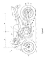
- FIG. 1 is a side view illustrating a general configuration for a motorcycle 1 according to an embodiment of the present invention.
- the motorcycle 1 includes a main frame 2.
- a head pipe 3 is arranged to run through an upper part of the front end portion of the main frame 2.
- a steering shaft 4 is inserted into the head pipe 3.
- a pair of handlebars 5 is connected to the upper end portion of the steering shaft 4.
- On the righthand side of one of the handlebars 5, is arranged a brake lever (not shown).
- a pair of extendable and shrinkable (telescopic) front forks 7 are connected to the lower end portion of the steering shaft 4. Thus, by turning the handlebars 5, the front forks 7 swing.
- a front wheel 8 is attached rotatably to the lower end of the front forks 7. As the front forks 7 extend or contract, the vibrations of the front wheel 8 are damped.
- a front wheel brake 10 is attached to the lower end of the front forks 7 so that the rider can brake the front wheel 8 rotating by turning the brake lever.
- a front wheel speed sensor 35 is also arranged near the lower end of the front forks 7 to detect and output the rotational velocity of the front wheel 8.
- a front fender 11 is secured to the front forks 7 over the front wheel 8.
- a fuel tank 15 and a seat 16 are arranged in line along the main frame 2. Under the fuel tank 15, an engine 17 and a gearbox 18 are held by the main frame 2.
- the engine 17 is provided with a spark plug 39, a fuel injection system 40 and a throttle actuator 41.
- a throttle sensor 37 which detects and outputs the position of an Electronic Throttle Valve (ETV) and a driving source rotating speed sensor 42 which detects and outputs the engine speed are also provided.
- ETV Electronic Throttle Valve
- a clutch 13 is arranged between the engine 17 and the gearbox 18.
- the gearbox 18 has a drive shaft 19 which outputs the power that has been generated by the engine 17.
- a drive sprocket 20 is connected to the drive shaft 19.
- the power generated by the engine 17 is selectively output to the drive shaft 19 by engaging or disengaging the clutch 13.
- the gearbox 18 includes a plurality of gears, and changes the number of revolutions that have been transmitted from the engine 17 at one of multiple transmission gear ratios that has been selected, thereby rotating and driving the drive shaft 19.
- a pair of swing arms 21 is supported under and behind the main frame 2. At the rear end of the swing arms 21, a driven sprocket 22 and a rear wheel 23 are supported rotatably.
- a rear wheel speed sensor 36 which detects and outputs the rotational velocity of the rear wheel 23 is arranged near the driven sprocket 22.
- a rear wheel brake 26 which works by pumping a pedal brake (not shown) is provided for the rear wheel 23.
- a chain 24 is suspended between the drive sprocket 20 and the driven sprocket 22. The driving force generated by the engine 17 is transmitted to the rear wheel 23 via the clutch 13, gearbox 18, drive shaft 19, drive sprocket 20, chain 24 and driven sprocket 22.
- a brake modulator 38 Under the seat 16, arranged are a brake modulator 38 and an Electronic Control Unit (ECU) 31 which controls the operations of respective parts of this motorcycle 1.
- the ECU 31 may be implemented as a combination of a microcomputer and a memory which stores a program defining the procedure of controlling the operations of respective parts of the motorcycle 1, for example.
- the brake modulator 38 detects the braking pressures on the front and rear wheel brakes 10 and 26 (i.e. the magnitude of the braking force), and adjusts the braking pressures on the front and rear wheel brakes 10 and 26 in response to operations on the brake lever and the brake pedal.
- This motorcycle 1 further includes a gyroscope 33 and an acceleration sensor 34 and detects the bank angle of the vehicle using the gyroscope 33 and the acceleration sensor 34.
- the motorcycle 1 may include a hexaxial inertial measurement unit as the gyroscope 33 and acceleration sensor 34.
- FIG. 2 is a functional block diagram of the ECU 31, which includes an absolute bank angle detector 51, a corner estimation calculation circuit 53, a basic target position calculation circuit 55, a relative bank angle calculation circuit 57, and a corrected target position calculation circuit 59.
- the functions of these components can be carried out by making a microcomputer retrieve and execute a program that is stored in a memory.
- the ECU 31 may also have the function of controlling the respective parts of the motorcycle 1 in addition to these components.
- at least some of these components of the ECU 31 may be included in a different control unit from the ECU 31.
- the ECU 31 controls the driving force based on a relative bank angle that is the motorcycle's 1 relative bank angle with respect to a maximum absolute bank angle. Next, it will be described what is meant herein by the absolute bank angle, maximum absolute bank angle and relative bank angle.
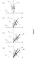
- Figures 3(a) to (d) illustrate what is meant by the absolute bank angle, maximum absolute bank angle and relative bank angle using a motorcycle 1 as viewed from right behind it.
- Figure 3(a) illustrates a situation where the motorcycle 1 is standing upright.
- the height direction 65 of the motorcycle 1 agrees with the vertically upward direction 61 and the angle formed between these two directions is zero degrees.
- the horizontal direction 63 intersects at right angles with the vertically upward direction 61.
- a motorcycle 1 running straight forward is in the state shown in Figure 3(a) .
- the motorcycle 1 will gradually get up itself to the upright position.
- the angle formed between the height direction 65m associated with the maximum absolute bank angle ⁇ m and the current height direction 65 increases gradually.
- Such an angle ⁇ r defined by the current height direction 65 with respect to the height direction 65m associated with the maximum absolute bank angle ⁇ m will be hereinafter referred to as a "relative bank angle”.
- the relative bank angle is a relative angle defined by the motorcycle 1 with respect to the maximum absolute bank angle ⁇ m. According to this embodiment, the driving force is controlled based on this relative bank angle ⁇ r.
- the acceleration position sensor 43 detects the accelerator position angle that changes as the rider twists the accelerator grip, and outputs such to the basic target position calculation circuit 55.
- the driving source rotating speed sensor 42 detects the speed of the engine 17 and outputs it to the basic target position calculation circuit 55.
- the basic target position calculation circuit 55 defines an accelerator-throttle characteristic, representing how the throttle position angle changes with the accelerator position angle, based on the accelerator position angle and the speed of the engine 17.
- the accelerator-throttle characteristic defined by the basic target position calculation circuit 55 may be a characteristic when the motorcycle 1 is going straight (or standing upright).
- Figure 4 shows how the accelerator-throttle characteristic 71 varies when the motorcycle 1 is going straight forward (standing upright). As shown in Figure 4 , as the accelerator position angle increases, the throttle position angle increases gradually.
- the basic target position calculation circuit 55 outputs information about such an accelerator-throttle characteristic 71 to a corrected target position calculation circuit 59.
- the acceleration sensor 34 detects acceleration on the motorcycle 1 and outputs such to the absolute bank angle detector 51.
- the gyroscope 33 detects the angular velocity of the motorcycle 1 and outputs such to the absolute bank angle detector 51.
- the absolute bank angle detector 51 detects the absolute bank angle ⁇ a of the motorcycle 1 based on the acceleration and the angular velocity.
- a known method may be used to obtain the absolute bank angle ⁇ a based on the acceleration and/or angular velocity, and detailed description thereof will be omitted herein. Also, as long as the absolute bank angle ⁇ a can be obtained, parameters other than the acceleration and angular velocity may also be used to calculate the absolute bank angle ⁇ a.
- the front wheel speed sensor 35 detects the rotational velocity of the front wheel 8 and outputs such to the corner estimation calculation circuit 53. Meanwhile, the accelerator position sensor 43 outputs the accelerator position angle detected to the corner estimation calculation circuit 53. Based on the accelerator position angle and the variation in front wheel speed, the corner estimation calculation circuit 53 determines whether or not to reset the maximum absolute bank angle ⁇ m. The resetting processing will be described in detail later.
- the relative bank angle calculation circuit 57 obtains information about the absolute bank angle ⁇ a from the absolute bank angle detector 51 and also obtains information indicating whether or not the maximum absolute bank angle ⁇ m should be reset from the corner estimation calculation circuit 53.
- the relative bank angle calculation circuit 57 determines the value of the maximum absolute bank angle ⁇ m by monitoring a variation in absolute bank angle ⁇ a.
- the maximum absolute bank angle ⁇ m may be set to be an angle at which the absolute bank angle ⁇ a that has been rising starts to fall.
- the relative bank angle calculation circuit 57 calculates the relative bank angle ⁇ r that has already been described with reference to Figure 3(d) and outputs such to the corrected target position calculation circuit 59.
- the corrected target position calculation circuit 59 determines the accelerator-throttle characteristic to be used to control the throttle actuator 41 by reference to information provided by the basic target position calculation circuit 55 about the accelerator-throttle characteristic, information provided by the absolute bank angle detector 51 about the absolute bank angle ⁇ a, and information provided by the relative bank angle calculation circuit 57 about the relative bank angle ⁇ r, and changes that accelerator-throttle characteristic according to the relative bank angle ⁇ r.
- FIG. 5 shows how the accelerator-throttle characteristic changes.
- the corrected target position calculation circuit 59 controls the throttle actuator 41 using the accelerator-throttle characteristic 71.
- the throttle can be wide open just by turning the accelerator a little. That is to say, in such a situation, the rider needs to move their hands or fingers much less, and therefore, can drive or ride the motorcycle 1 straight forward without re-gripping the accelerator or making any other troublesome manipulation.
- the throttle actuator 41 is controlled by adopting the accelerator-throttle characteristic 75 in which the throttle position angle rises gently with respect to the accelerator position angle.
- the relative bank angle ⁇ r also increases gradually.
- the throttle actuator 41 is controlled by adopting an intermediate characteristic between the characteristics 71 and 75 (such as the accelerator-throttle characteristic 73).
- the throttle actuator 41 will start to be controlled using the accelerator-throttle characteristic 71. In this manner, the rider can accelerate the motorcycle smoothly after having rounded a corner.
- the driving force is controlled based on the relative bank angle ⁇ r.
- the relative bank angle ⁇ r is small, an accelerator-throttle characteristic in which the ratio of the throttle position angle to the accelerator position angle is small is used. And as the relative bank angle ⁇ r increases, the accelerator-throttle characteristic is turned into a characteristic in which the throttle position angle changes significantly with respect to the accelerator position angle.
- the driving force can be controlled every time by using the relative bank angle ⁇ r.
- the relative bank angle ⁇ r it is possible to prevent the rider from finding the behavior of the vehicle unnatural or uncomfortable.
- the values of the acceleration sensor 34 and gyroscope 33 deviate significantly from their normal values due to disturbance, for example, those deviations can be canceled by using the relative bank angle ⁇ r.
- FIG. 31 shows how the ECU 31 may change the modes of its processing according to the running state of the motorcycle 1.
- Figure 6 shows how respective parameters change as the running state of the motorcycle 1 changes.
- Figure 7 is a flowchart showing the procedure of the processing to be carried out by the ECU 31.
- the running state C1 is a state where the motorcycle 1 has started to slow down at a straight before entering a corner. While the motorcycle 1 is slowing down in this manner, the decision is made whether the maximum absolute bank angle ⁇ m may be reset or not.
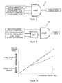
- Figure 8 shows a condition C11 on which the maximum absolute bank angle ⁇ m may be reset. Specifically, the maximum absolute bank angle ⁇ m may be reset if:
- the decision is made that the vehicle has slowed down. It should be noted that the front wheel speed is used to make this decision because the rear wheel may sometimes be in the air when braked. Further, since the decision only needs to be made whether the vehicle has slowed down or not, an acceleration sensor may be used, for example.
- the decision is made that the vehicle is standing upright. If the vehicle is slowing down while rounding a curve, when the absolute bank angle becomes greater than a predetermined value, the maximum absolute bank angle ⁇ m may not be reset, and the control is carried out using the same maximum absolute bank angle ⁇ m with even multiple corners regarded as a single corner.
- the resetting decision can be made even more accurately.
- condition C11 on which resetting is allowed is just an example. Thus, the decision can be made more accurately by adding any other condition.
- the next running state C2 is a state where the vehicle has finished slowing down and has entered a corner.
- the maximum absolute bank angle ⁇ m is reset and updated.
- resetting and updating are supposed to be made simultaneously. It should be noted that resetting does not mean changing the value to zero but starting to measure the maximum absolute bank angle ⁇ m at that corner. Until the maximum absolute bank angle ⁇ m is updated, the previous value will be held continuously.
- Figure 9 shows a condition C21 on which the maximum absolute bank angle ⁇ m may start to be updated. Specifically, the maximum absolute bank angle ⁇ m may start to be updated if at least one of:
- the decision is made that the vehicle is rounding a corner at an absolute bank angle ⁇ a that is equal to or higher than a certain level. In this case, if the vehicle is almost standing upright, no driving force reduction control is carried out. The reason is that the driving force reduction control should be carried out to lighten the rider's load of turning the accelerator finely while the motorcycle is rounding a curve at a large absolute bank angle ⁇ a.
- the decision is made that the driving force is being applied to accelerate the motorcycle.
- the speed i.e. the engine speed
- the maximum absolute bank angle should be updated on and after a timing or period when the driving force has reached a level at which the vehicle starts to accelerate.
- the driving force reduction control is started in such a range in which the engine speed slows down automatically, the accelerator position angle should be larger than usual to bring the driving force to the level at which the vehicle starts to accelerate.
- the driving force reduction control is carried out in order to make the accelerating driving force controllable more easily. That is why as long as the driving force is applied so as to slow down the vehicle, no driving force reduction control is carried out.
- the engine torque may also be detected by sensing an increase or decrease in engine speed as well.
- FIG 10 shows how the accelerator-throttle characteristic changes with the engine torque.
- the throttle actuator 41 is controlled by adopting the accelerator-throttle characteristic 75 that is used when the vehicle is standing upright. And if the engine torque has become positive (i.e. has entered the accelerating range), the throttle actuator 41 is controlled by adopting the accelerator-throttle characteristic 75.
- the maximum absolute bank angle ⁇ m continues to be updated. In performing the processing of updating the maximum absolute bank angle ⁇ m, if:
- control based on the relative bank angle ⁇ r is carried out within the range of the maximum absolute bank angle to the control-ending relative bank angle (in Steps S16, S17 and S18).
- control-ending relative bank angle refers herein to an angle at which the control based on the relative bank angle ⁇ r is ended, and may be set to be any arbitrary angle.
- bank angle corrected target position angle refers herein to a position angle associated with the accelerator-throttle characteristic 75 when the vehicle is running at the maximum absolute bank angle ⁇ m (i.e. at a relative bank angle ⁇ r of zero).
- the driving force is not controlled but the throttle actuator 41 is controlled in accordance with the accelerator-throttle characteristic 71 to be used in the upright position. That is to say, the throttle actuator 41 is controlled based on the basic target position angle to be used in the upright position (in Steps S19 and S20).
- FIGS 11 (a) and (b) show how the accelerator-throttle characteristic changes with the bank angle.
- the "current value” is a value falling within the range of the maximum absolute bank angle ⁇ m to the control-ending relative bank angle ⁇ r1.
- the throttle actuator 41 is controlled using the accelerator-throttle characteristic 73, of which the values are intermediate ones between those of the accelerator-throttle characteristics 71 and 75. And in the interval after the control-ending relative bank angle ⁇ r1 has been reached and before the vehicle recovers the upright position, the throttle actuator 41 is controlled in accordance with the accelerator-throttle characteristic 71 to be used in the upright position.
- Figure 12 shows how to perform the resetting and updating processing when the vehicle is rounding an S-curve.
- the motorcycle 1 is going to round an S-curve which makes the motorcycle 1 turn right first and then turn left.
- the maximum absolute bank angle ⁇ m is updated, and the driving force is controlled based on the relative bank angle ⁇ r associated with the newest maximum absolute bank angle ⁇ m.
- the maximum absolute bank angle ⁇ m is reset.
- the maximum absolute bank angle ⁇ m is updated, and the driving force is controlled based on the relative bank angle ⁇ r associated with the newest maximum absolute bank angle ⁇ m. In this manner, the driving force can be controlled based on the relative bank angle ⁇ r while the motorcycle 1 is turning right and left.
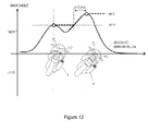
- Figure 13 shows how to perform the resetting and updating processing when the motorcycle 1 needs to go through a double apex corner in which there are a series of two corners with different radii of curvature.
- the motorcycle 1 rounds the first curve at a small bank angle and then rounds the second curve at a larger bank angle than when rounding the first curve.
- the driving force is controlled based on the relative bank angle ⁇ r associated with the maximum absolute bank angle ⁇ m1.
- the driving force is controlled based on the relative bank angle ⁇ r associated with the maximum absolute bank angle ⁇ m2 updated. In this manner, the driving force can be controlled based on the relative bank angle ⁇ r while the motorcycle 1 is rounding each of those curves.
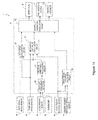
- Figure 14 is a functional block diagram of an ECU 31 which carries out a traction control based on the relative bank angle ⁇ r.
- the magnitude of slipping of the rear wheel 23 is calculated, and a reference slip value to be a threshold value at which the driving force reduction control is started is also calculated, thereby determining, based on these values, how much the driving force should be reduced.
- the ECU 31 shown in Figure 14 includes an absolute bank angle detector 51, a basic target position calculation circuit 55, a relative bank angle calculation circuit 57, a slip value calculation circuit 91, a reference slip value calculation circuit 93, and a degree of reduction calculation circuit 95.
- the absolute bank angle detector 51, basic target position calculation circuit 55, and relative bank angle calculation circuit 57 operate just as described above.
- the front wheel speed sensor 35 detects the rotational velocity of the front wheel 8 and outputs such to the slip value calculation circuit 91 and the reference slip value calculation circuit 93.
- the rear wheel speed sensor 36 detects the rotational velocity of the rear wheel 23 and outputs such to the slip value calculation circuit 91.
- the relative bank angle calculation circuit 57 calculates a relative bank angle ⁇ r and outputs such to the slip value calculation circuit 91 and reference slip value calculation circuit 93.
- the accelerator position sensor 43 detects an accelerator position angle and outputs such to the reference target position calculation circuit 55 and reference slip value calculation circuit 93.
- the slip value calculation circuit 91 calculates the current slip value of the rear wheel 23 based on the difference in velocity between the front and rear wheels and the relative bank angle ⁇ r. Alternatively, the slip value calculation circuit 91 may also calculate the current slip value of the rear wheel 23 based on the difference in velocity between the front and rear wheels and the absolute bank angle ⁇ a.
- the reference slip value calculation circuit 93 calculates a slip value to be a threshold value at which the traction control is turned ON and OFF based on the rotational velocity of the front wheel 8, the relative bank angle ⁇ r and the accelerator position angle. For example, if the relative bank angle ⁇ r is small (i.e. if the vehicle is banked significantly), the magnitude of permissible slipping is small, and therefore, the threshold slip value is set to be low enough to let the traction control interfere easily. On the other hand, if the relative bank angle ⁇ r is large (if the vehicle is banked just slightly), the magnitude of permissible slipping is large, and therefore, the threshold slip value is set to be too high to let the traction control interfere easily.
- the degree of reduction calculation circuit 95 compares the current slip value of the rear wheel 23 and the slip value to be the threshold value to each other, and initiates the traction control if the current slip value of the rear wheel 23 turns out to be equal to or greater than the threshold slip value. In this case, if the current slip value of the rear wheel 23 is far greater than the threshold slip value, the degree of reduction is increased to stabilize the vehicle's behavior. On the other hand, if the current slip value of the rear wheel 23 is less than the threshold slip value, then no traction control is performed.
- the degree of reduction calculation circuit 95 controls the degree of reduction of the driving force by adjusting the ignition time lag of the spark plug 39, for example. Additionally or alternatively, the degree of reduction calculation circuit 95 controls the degree of reduction of the driving force by adjusting the injection rate of the fuel injection system 40, for example. Alternatively or additionally, the degree of reduction of the driving force may also be controlled by adjusting the throttle position angle of the throttle actuator 41.
- the traction control is carried out based on the relative bank angle ⁇ r.
- the vehicle can be accelerated to a required degree on a road with a cant or camber as described above, and the rear wheel 23 can be prevented from sliding when the vehicle is running on a wet or slippery road.
- the driving force can be controlled every time by using the relative bank angle ⁇ r. As a result, it is possible to prevent the rider from finding the behavior of the vehicle unnatural or uncomfortable.
- the vehicle's running performance can be improved by controlling the driving force more precisely and accurately while the vehicle is rounding a curve or bend.
- control operation that has been described in the foregoing description of embodiments may be implemented by hardware circuits, software program, or a combination thereof.
- a computer program which is defined to perform that operation may be stored in a memory provided for the ECU 31, for example, and the operation can be carried out by the ECU 31 (that is a computer).
- a computer program may be installed from a storage medium (such as a semiconductor memory or an optical disc) on which the program is stored into the motorcycle 1 or downloaded through the Internet or any other telecommunications lines or channels.
- a computer program may be installed into the motorcycle 1 via wireless communication.
- the present invention can be used particularly effectively for a vehicle which banks while rounding a curve.
- saddled vehicle or motor vehicle used herein, and as used in the art, is intended to include at least the following terms, also used in the art:
Landscapes
- Engineering & Computer Science (AREA)
- Mechanical Engineering (AREA)
- Chemical & Material Sciences (AREA)
- Combustion & Propulsion (AREA)
- Transportation (AREA)
- General Engineering & Computer Science (AREA)
- Automation & Control Theory (AREA)
- Control Of Vehicle Engines Or Engines For Specific Uses (AREA)
- Control Of Throttle Valves Provided In The Intake System Or In The Exhaust System (AREA)
- Electrical Control Of Air Or Fuel Supplied To Internal-Combustion Engine (AREA)
- Combined Controls Of Internal Combustion Engines (AREA)
Applications Claiming Priority (1)
| Application Number | Priority Date | Filing Date | Title |
|---|---|---|---|
| JP2014179161A JP5945572B2 (ja) | 2014-09-03 | 2014-09-03 | 駆動力制御システムおよび鞍乗り型車両 |
Publications (2)
| Publication Number | Publication Date |
|---|---|
| EP2993333A1 true EP2993333A1 (de) | 2016-03-09 |
| EP2993333B1 EP2993333B1 (de) | 2016-10-05 |
Family
ID=52103045
Family Applications (1)
| Application Number | Title | Priority Date | Filing Date |
|---|---|---|---|
| EP14196399.1A Active EP2993333B1 (de) | 2014-09-03 | 2014-12-04 | Antriebskraftsteuerungssystem und Sattelfahrzeug |
Country Status (3)
| Country | Link |
|---|---|
| US (1) | US9758041B2 (de) |
| EP (1) | EP2993333B1 (de) |
| JP (1) | JP5945572B2 (de) |
Cited By (2)
| Publication number | Priority date | Publication date | Assignee | Title |
|---|---|---|---|---|
| US9758041B2 (en) | 2014-09-03 | 2017-09-12 | Yamaha Hatsudoki Kabushiki Kaisha | Driving force control system and saddled vehicle |
| WO2018219520A1 (de) * | 2017-05-31 | 2018-12-06 | Robert Bosch Gmbh | Verfahren und vorrichtung zur beeinflussung der motorsteuerung eines einspurigen kraftfahrzeugs |
Families Citing this family (19)
| Publication number | Priority date | Publication date | Assignee | Title |
|---|---|---|---|---|
| DE102013212606A1 (de) * | 2013-06-28 | 2014-12-31 | Robert Bosch Gmbh | Verfahren zur querdynamischen Stabilisierung eines einspurigen Kraftfahrzeugs |
| WO2015186213A1 (ja) * | 2014-06-04 | 2015-12-10 | 株式会社エフ・シ-・シ- | 鞍乗り型車両 |
| DE102015202115A1 (de) * | 2015-02-06 | 2016-08-11 | Robert Bosch Gmbh | Verfahren zur Bestimmung des Schräglagenwinkels eines Zweirads |
| FR3038480B1 (fr) | 2015-07-03 | 2018-11-16 | Somfy Sas | Procede d’enregistrement d’une unite centrale de commande appartenant a une installation domotique |
| FR3038478B1 (fr) | 2015-07-03 | 2018-07-06 | Somfy Sas | Installation domotique et procede de constitution de la topologie d’une installation domotique |
| US9840239B2 (en) * | 2015-10-13 | 2017-12-12 | Robert Bosch Gmbh | Cornering brake control |
| JP2017210896A (ja) * | 2016-05-24 | 2017-11-30 | スズキ株式会社 | 過給圧制御装置 |
| DE102016211421A1 (de) * | 2016-06-27 | 2017-12-28 | Robert Bosch Gmbh | Verfahren zur querdynamischen Stabilisierung eines einspurigen Kraftfahrzeugs |
| JP6823664B2 (ja) * | 2016-10-19 | 2021-02-03 | 川崎重工業株式会社 | タイヤ力推定装置およびタイヤ力推定方法 |
| JP6907554B2 (ja) * | 2017-01-24 | 2021-07-21 | スズキ株式会社 | 走行制御装置 |
| JP6907555B2 (ja) * | 2017-01-24 | 2021-07-21 | スズキ株式会社 | 走行制御装置 |
| JP6991435B2 (ja) * | 2017-04-19 | 2022-01-12 | カワサキモータース株式会社 | 縦力制御装置および縦力制御方法 |
| JP7015161B2 (ja) * | 2017-12-11 | 2022-02-02 | カワサキモータース株式会社 | リーン型乗物の走行情報蓄積方法、走行情報処理プログラム及び走行情報蓄積装置 |
| JP2020029176A (ja) * | 2018-08-23 | 2020-02-27 | ロベルト・ボッシュ・ゲゼルシャフト・ミト・ベシュレンクテル・ハフツングRobert Bosch Gmbh | 制御装置及び制御方法 |
| JP7171457B2 (ja) | 2019-01-25 | 2022-11-15 | 三菱重工業株式会社 | 粉塵回収装置及びそれを備えた排ガス処理装置並びに粉塵回収方法 |
| JP7248478B2 (ja) * | 2019-03-28 | 2023-03-29 | 本田技研工業株式会社 | 車両制御装置、端末装置、サーバ装置、車両、車両制御システム及び車両制御方法 |
| DE102020101650A1 (de) | 2020-01-24 | 2021-07-29 | Bayerische Motoren Werke Aktiengesellschaft | Verfahren zum Beeinflussen einer Schräglage eines Einspurfahrzeugs |
| EP4331937B1 (de) * | 2021-04-29 | 2025-12-24 | Robert Bosch GmbH | Steuerungsvorrichtung und steuerungsverfahren für fahrerassistenzsystem |
| EP4434835A2 (de) * | 2021-11-17 | 2024-09-25 | Robert Bosch GmbH | Steuerungsvorrichtung und steuerungsverfahren |
Citations (6)
| Publication number | Priority date | Publication date | Assignee | Title |
|---|---|---|---|---|
| DE10242124A1 (de) * | 2002-09-11 | 2004-03-25 | Robert Bosch Gmbh | Verfahren und Vorrichtung zur Einstellung des Motormoments eines einspurigen Kraftfahrzeugs |
| DE102005003981A1 (de) * | 2005-01-28 | 2006-08-17 | Bayerische Motoren Werke Ag | Verfahren zur Antriebsmomentregelung bei einem einspurigen Kraftfahrzeug |
| EP1714862A2 (de) * | 2005-03-29 | 2006-10-25 | Yamaha Hatsudoki Kabushiki Kaisha | Betriebssteuervorrichtung für ein Sattelkraftfahrzeug |
| JP2011185107A (ja) | 2010-03-05 | 2011-09-22 | Kokusan Denki Co Ltd | 自動二輪車用エンジン制御装置 |
| WO2014017138A1 (ja) * | 2012-07-25 | 2014-01-30 | ボッシュ株式会社 | 二輪車の転倒防止方法及び装置 |
| EP2738075A1 (de) * | 2011-07-28 | 2014-06-04 | Yamaha Hatsudoki Kabushiki Kaisha | Haltungskontrollvorrichtung und grätschsitzfahrzeug damit |
Family Cites Families (47)
| Publication number | Priority date | Publication date | Assignee | Title |
|---|---|---|---|---|
| JP2618250B2 (ja) * | 1987-12-22 | 1997-06-11 | 富士重工業株式会社 | トラクション制御装置 |
| DE19734112B4 (de) * | 1997-08-07 | 2007-12-27 | Robert Bosch Gmbh | Verfahren und Vorrichtung zur Antriebsschlupfregelung bei Kraftfahrzeugen |
| DE19751867A1 (de) * | 1997-11-22 | 1999-05-27 | Bosch Gmbh Robert | Verfahren und Vorrichtung zur Erkennung einer Kipptendenz eines Fahrzeuges |
| KR100572500B1 (ko) * | 1998-04-07 | 2006-04-24 | 로베르트 보쉬 게엠베하 | 차량의 안정화 방법 및 장치 |
| JP3669668B2 (ja) | 1998-07-10 | 2005-07-13 | 本田技研工業株式会社 | 車両用車輪スリップ角検出装置 |
| DE19933084B4 (de) * | 1999-07-15 | 2014-01-09 | Robert Bosch Gmbh | Verfahren und Vorrichtung zur Steuerung des Schlupfes eines Fahrzeugrades |
| JP3868848B2 (ja) * | 2002-05-23 | 2007-01-17 | 三菱電機株式会社 | 車両状態検出装置 |
| DE10232362B4 (de) * | 2002-07-17 | 2018-03-15 | Robert Bosch Gmbh | Verfahren und Vorrichtung zur Stabilisierung eines einspurigen Kraftfahrzeugs |
| US7006901B2 (en) * | 2002-11-18 | 2006-02-28 | Wang Everett X | Computerized automated dynamic control system for single-track vehicles |
| JP4207698B2 (ja) * | 2003-07-17 | 2009-01-14 | 株式会社アドヴィックス | 車両の横転防止装置 |
| JP2005047314A (ja) * | 2003-07-30 | 2005-02-24 | Toyota Motor Corp | スリップ判定装置およびスリップ判定方法並びに車両 |
| JP2005061376A (ja) | 2003-08-20 | 2005-03-10 | Keihin Corp | 二輪自動車の出力制御装置 |
| JP4246609B2 (ja) * | 2003-11-27 | 2009-04-02 | チコーエアーテック株式会社 | ヒューム捕集機 |
| EP1720739B1 (de) * | 2004-03-01 | 2013-04-03 | Continental Teves AG & Co. oHG | Vorrichtung zum ermitteln einer kipptendenz |
| JP4586962B2 (ja) * | 2004-04-20 | 2010-11-24 | トヨタ自動車株式会社 | 車両の姿勢制御装置 |
| DE102004040140A1 (de) * | 2004-08-19 | 2006-02-23 | Robert Bosch Gmbh | Verfahren und Vorrichtung zur Behebung einer Umkippgefahr eines Kraftfahrzeugs |
| US7668637B2 (en) * | 2005-07-22 | 2010-02-23 | O'dea Kevin Austin | Technique for determining motor vehicle slip angle while accounting for road banks |
| JP4730065B2 (ja) * | 2005-11-14 | 2011-07-20 | 株式会社アドヴィックス | 車両の運動制御装置 |
| EP1998989B1 (de) * | 2006-03-21 | 2015-07-01 | Koninklijke Philips N.V. | Vorrichtung und verfahren zur bestimmung des wankwinkels eines motorrades |
| JP2008231990A (ja) | 2007-03-19 | 2008-10-02 | Yamaha Motor Co Ltd | 自動二輪車 |
| US8423274B2 (en) * | 2007-03-27 | 2013-04-16 | Equos Research Co., Ltd. | Vehicle |
| JP4879081B2 (ja) * | 2007-04-27 | 2012-02-15 | 川崎重工業株式会社 | 乗り物 |
| DE102008019194A1 (de) * | 2008-04-17 | 2009-10-22 | Wabco Gmbh | Verfahren und Vorrichtung zur Stabilitätsregelung eines Fahrzeuges, insbesondere Nutzfahrzeuges |
| EP2138367B1 (de) * | 2008-06-26 | 2015-05-13 | Kawasaki Jukogyo Kabushiki Kaisha | Schlupfregelsystem für Fahrzeug |
| EP2138366B1 (de) * | 2008-06-26 | 2013-03-20 | Kawasaki Jukogyo Kabushiki Kaisha | Schlupfunterdrückungssteuersystem für Fahrzeuge |
| US8352116B2 (en) * | 2009-01-15 | 2013-01-08 | Delta Systems, Inc. | Tilt and/or acceleration sensing apparatus and method |
| IT1394715B1 (it) | 2009-06-09 | 2012-07-13 | Milano Politecnico | Sistema e metodo di controllo della trazione in un veicolo a due ruote |
| US9403415B2 (en) * | 2009-10-12 | 2016-08-02 | Ford Global Technologies | GPS based pitch sensing for an integrated stability control system |
| JP5251835B2 (ja) | 2009-11-06 | 2013-07-31 | 国産電機株式会社 | 自動二輪車用エンジン制御装置 |
| JP2011152834A (ja) * | 2010-01-26 | 2011-08-11 | Toyota Motor Corp | 車両およびその制御方法 |
| DE102010003951A1 (de) * | 2010-04-14 | 2011-10-20 | Robert Bosch Gmbh | Verfahren zum Stabilisieren eines Zweirads bei seitlich rutschendem Hinterrad |
| JP5466126B2 (ja) * | 2010-09-30 | 2014-04-09 | 本田技研工業株式会社 | 自動二輪車の姿勢制御装置及び自動二輪車 |
| JP5713741B2 (ja) * | 2011-03-18 | 2015-05-07 | 本田技研工業株式会社 | 自動二輪車の変速制御装置 |
| ITMI20111729A1 (it) * | 2011-09-26 | 2013-03-27 | Shock S R L E | Metodo e sistema per il controllo di stabilità di un veicolo a due ruote mediante sospensione elettronicamente modulabile |
| JP5697183B2 (ja) * | 2012-01-31 | 2015-04-08 | ヤマハ発動機株式会社 | ブレーキ装置及び鞍乗型車両 |
| EP2813691B1 (de) * | 2012-02-10 | 2018-09-05 | Yamaha Hatsudoki Kabushiki Kaisha | Fahrzeug und vorrichtung zur steuerung einer luftansaugmenge dafür |
| JP5926095B2 (ja) | 2012-03-30 | 2016-05-25 | 本田技研工業株式会社 | 自動二輪車用トラクション制御装置 |
| CA2917052A1 (en) * | 2012-07-10 | 2014-01-16 | Gotech International Limited | Steering and control systems for a three-wheeled vehicle |
| WO2014022315A2 (en) * | 2012-07-31 | 2014-02-06 | Helix Motors International, Inc. | Three-wheeled tilting vehicle |
| JP5865509B2 (ja) * | 2012-10-22 | 2016-02-17 | 川崎重工業株式会社 | 電動式乗物の回生ブレーキ制御システム |
| DE102012222884A1 (de) * | 2012-12-12 | 2014-06-12 | Robert Bosch Gmbh | Verfahren zur Stabilisierung eines Zweirads |
| JP6148592B2 (ja) * | 2013-10-15 | 2017-06-14 | ヤマハ発動機株式会社 | 車速決定システム、安定制御システム及びそれを備えた鞍乗り型車両 |
| JP5844331B2 (ja) * | 2013-10-21 | 2016-01-13 | ヤマハ発動機株式会社 | 縦力制御装置およびそれを備えた鞍乗り型車両 |
| JP5955306B2 (ja) * | 2013-12-09 | 2016-07-20 | 本田技研工業株式会社 | 移動車両 |
| WO2015133397A1 (ja) * | 2014-03-03 | 2015-09-11 | ボッシュ株式会社 | 二輪車用ブレーキ装置の制動力制御方法及び制動力制御装置 |
| JP5945571B2 (ja) * | 2014-09-03 | 2016-07-05 | ヤマハ発動機株式会社 | トラクション制御システムおよび鞍乗り型車両 |
| JP5945572B2 (ja) | 2014-09-03 | 2016-07-05 | ヤマハ発動機株式会社 | 駆動力制御システムおよび鞍乗り型車両 |
-
2014
- 2014-09-03 JP JP2014179161A patent/JP5945572B2/ja active Active
- 2014-12-04 EP EP14196399.1A patent/EP2993333B1/de active Active
- 2014-12-10 US US14/566,705 patent/US9758041B2/en active Active
Patent Citations (6)
| Publication number | Priority date | Publication date | Assignee | Title |
|---|---|---|---|---|
| DE10242124A1 (de) * | 2002-09-11 | 2004-03-25 | Robert Bosch Gmbh | Verfahren und Vorrichtung zur Einstellung des Motormoments eines einspurigen Kraftfahrzeugs |
| DE102005003981A1 (de) * | 2005-01-28 | 2006-08-17 | Bayerische Motoren Werke Ag | Verfahren zur Antriebsmomentregelung bei einem einspurigen Kraftfahrzeug |
| EP1714862A2 (de) * | 2005-03-29 | 2006-10-25 | Yamaha Hatsudoki Kabushiki Kaisha | Betriebssteuervorrichtung für ein Sattelkraftfahrzeug |
| JP2011185107A (ja) | 2010-03-05 | 2011-09-22 | Kokusan Denki Co Ltd | 自動二輪車用エンジン制御装置 |
| EP2738075A1 (de) * | 2011-07-28 | 2014-06-04 | Yamaha Hatsudoki Kabushiki Kaisha | Haltungskontrollvorrichtung und grätschsitzfahrzeug damit |
| WO2014017138A1 (ja) * | 2012-07-25 | 2014-01-30 | ボッシュ株式会社 | 二輪車の転倒防止方法及び装置 |
Cited By (3)
| Publication number | Priority date | Publication date | Assignee | Title |
|---|---|---|---|---|
| US9758041B2 (en) | 2014-09-03 | 2017-09-12 | Yamaha Hatsudoki Kabushiki Kaisha | Driving force control system and saddled vehicle |
| WO2018219520A1 (de) * | 2017-05-31 | 2018-12-06 | Robert Bosch Gmbh | Verfahren und vorrichtung zur beeinflussung der motorsteuerung eines einspurigen kraftfahrzeugs |
| US11047317B2 (en) | 2017-05-31 | 2021-06-29 | Robert Bosch Gmbh | Method and device for influencing the engine control of a single-track motor vehicle |
Also Published As
| Publication number | Publication date |
|---|---|
| JP5945572B2 (ja) | 2016-07-05 |
| US9758041B2 (en) | 2017-09-12 |
| JP2016053324A (ja) | 2016-04-14 |
| US20160061132A1 (en) | 2016-03-03 |
| EP2993333B1 (de) | 2016-10-05 |
Similar Documents
| Publication | Publication Date | Title |
|---|---|---|
| EP2993333B1 (de) | Antriebskraftsteuerungssystem und Sattelfahrzeug | |
| EP2641819B1 (de) | Automatisches zweirädriges fahrzeug und steuerungsvorrichtung dafür | |
| EP2974900B1 (de) | Grätschsitzfahrzeug | |
| JP2016501156A (ja) | 二輪車を安定させる方法 | |
| US10843682B2 (en) | Vehicle controller | |
| US20170101008A1 (en) | Wheelie determining device, vehicle, and method of determining lift-off of wheel | |
| US10668902B2 (en) | Wheelie determining device and wheelie determining method | |
| JP6538200B2 (ja) | ウイリー制御装置及びその制御方法 | |
| EP1944186B1 (de) | Motorrad | |
| JP2010285987A (ja) | 二輪自動車のトラクション制御システムおよび制御方法 | |
| US11897332B2 (en) | Wheelie suppressing control unit | |
| US9440645B2 (en) | Traction control system and saddled vehicle | |
| JP5124398B2 (ja) | トルク推定システムおよび車両 | |
| WO2011070941A1 (ja) | 自動二輪車 | |
| JP7169201B2 (ja) | リーン車両の制御装置及び転倒予測方法 | |
| JP5978501B2 (ja) | 車両姿勢補正制御装置 | |
| EP4331925A1 (de) | Fahrsteuerungsvorrichtung | |
| JP4326316B2 (ja) | 車両のトラクションコントロール装置 | |
| JP6550747B2 (ja) | 車両の制御装置 | |
| JP3292494B2 (ja) | トラクションコントロール装置 | |
| JP2006298094A (ja) | 車両停止保持装置 | |
| JP6991435B2 (ja) | 縦力制御装置および縦力制御方法 |
Legal Events
| Date | Code | Title | Description |
|---|---|---|---|
| PUAI | Public reference made under article 153(3) epc to a published international application that has entered the european phase |
Free format text: ORIGINAL CODE: 0009012 |
|
| 17P | Request for examination filed |
Effective date: 20141204 |
|
| AK | Designated contracting states |
Kind code of ref document: A1 Designated state(s): AL AT BE BG CH CY CZ DE DK EE ES FI FR GB GR HR HU IE IS IT LI LT LU LV MC MK MT NL NO PL PT RO RS SE SI SK SM TR |
|
| AX | Request for extension of the european patent |
Extension state: BA ME |
|
| GRAP | Despatch of communication of intention to grant a patent |
Free format text: ORIGINAL CODE: EPIDOSNIGR1 |
|
| RIC1 | Information provided on ipc code assigned before grant |
Ipc: F02D 11/10 20060101ALI20160512BHEP Ipc: F02D 33/02 20060101ALN20160512BHEP Ipc: B60W 30/18 20120101ALI20160512BHEP Ipc: B60K 31/00 20060101ALI20160512BHEP Ipc: F02D 41/10 20060101AFI20160512BHEP Ipc: F02D 41/02 20060101ALI20160512BHEP |
|
| RIC1 | Information provided on ipc code assigned before grant |
Ipc: B60W 30/18 20120101ALI20160513BHEP Ipc: F02D 33/02 20060101ALN20160513BHEP Ipc: F02D 41/02 20060101ALI20160513BHEP Ipc: F02D 41/10 20060101AFI20160513BHEP Ipc: B60K 31/00 20060101ALI20160513BHEP Ipc: F02D 11/10 20060101ALI20160513BHEP |
|
| INTG | Intention to grant announced |
Effective date: 20160603 |
|
| GRAS | Grant fee paid |
Free format text: ORIGINAL CODE: EPIDOSNIGR3 |
|
| GRAA | (expected) grant |
Free format text: ORIGINAL CODE: 0009210 |
|
| AK | Designated contracting states |
Kind code of ref document: B1 Designated state(s): AL AT BE BG CH CY CZ DE DK EE ES FI FR GB GR HR HU IE IS IT LI LT LU LV MC MK MT NL NO PL PT RO RS SE SI SK SM TR |
|
| REG | Reference to a national code |
Ref country code: GB Ref legal event code: FG4D |
|
| REG | Reference to a national code |
Ref country code: CH Ref legal event code: EP |
|
| REG | Reference to a national code |
Ref country code: AT Ref legal event code: REF Ref document number: 834889 Country of ref document: AT Kind code of ref document: T Effective date: 20161015 |
|
| REG | Reference to a national code |
Ref country code: IE Ref legal event code: FG4D |
|
| REG | Reference to a national code |
Ref country code: DE Ref legal event code: R096 Ref document number: 602014004089 Country of ref document: DE |
|
| REG | Reference to a national code |
Ref country code: FR Ref legal event code: PLFP Year of fee payment: 3 |
|
| REG | Reference to a national code |
Ref country code: NL Ref legal event code: MP Effective date: 20161005 |
|
| REG | Reference to a national code |
Ref country code: LT Ref legal event code: MG4D |
|
| PG25 | Lapsed in a contracting state [announced via postgrant information from national office to epo] |
Ref country code: LV Free format text: LAPSE BECAUSE OF FAILURE TO SUBMIT A TRANSLATION OF THE DESCRIPTION OR TO PAY THE FEE WITHIN THE PRESCRIBED TIME-LIMIT Effective date: 20161005 |
|
| REG | Reference to a national code |
Ref country code: AT Ref legal event code: MK05 Ref document number: 834889 Country of ref document: AT Kind code of ref document: T Effective date: 20161005 |
|
| PG25 | Lapsed in a contracting state [announced via postgrant information from national office to epo] |
Ref country code: GR Free format text: LAPSE BECAUSE OF FAILURE TO SUBMIT A TRANSLATION OF THE DESCRIPTION OR TO PAY THE FEE WITHIN THE PRESCRIBED TIME-LIMIT Effective date: 20170106 Ref country code: LT Free format text: LAPSE BECAUSE OF FAILURE TO SUBMIT A TRANSLATION OF THE DESCRIPTION OR TO PAY THE FEE WITHIN THE PRESCRIBED TIME-LIMIT Effective date: 20161005 Ref country code: SE Free format text: LAPSE BECAUSE OF FAILURE TO SUBMIT A TRANSLATION OF THE DESCRIPTION OR TO PAY THE FEE WITHIN THE PRESCRIBED TIME-LIMIT Effective date: 20161005 Ref country code: NO Free format text: LAPSE BECAUSE OF FAILURE TO SUBMIT A TRANSLATION OF THE DESCRIPTION OR TO PAY THE FEE WITHIN THE PRESCRIBED TIME-LIMIT Effective date: 20170105 |
|
| PG25 | Lapsed in a contracting state [announced via postgrant information from national office to epo] |
Ref country code: IS Free format text: LAPSE BECAUSE OF FAILURE TO SUBMIT A TRANSLATION OF THE DESCRIPTION OR TO PAY THE FEE WITHIN THE PRESCRIBED TIME-LIMIT Effective date: 20170205 Ref country code: AT Free format text: LAPSE BECAUSE OF FAILURE TO SUBMIT A TRANSLATION OF THE DESCRIPTION OR TO PAY THE FEE WITHIN THE PRESCRIBED TIME-LIMIT Effective date: 20161005 Ref country code: PL Free format text: LAPSE BECAUSE OF FAILURE TO SUBMIT A TRANSLATION OF THE DESCRIPTION OR TO PAY THE FEE WITHIN THE PRESCRIBED TIME-LIMIT Effective date: 20161005 Ref country code: PT Free format text: LAPSE BECAUSE OF FAILURE TO SUBMIT A TRANSLATION OF THE DESCRIPTION OR TO PAY THE FEE WITHIN THE PRESCRIBED TIME-LIMIT Effective date: 20170206 Ref country code: RS Free format text: LAPSE BECAUSE OF FAILURE TO SUBMIT A TRANSLATION OF THE DESCRIPTION OR TO PAY THE FEE WITHIN THE PRESCRIBED TIME-LIMIT Effective date: 20161005 Ref country code: BE Free format text: LAPSE BECAUSE OF FAILURE TO SUBMIT A TRANSLATION OF THE DESCRIPTION OR TO PAY THE FEE WITHIN THE PRESCRIBED TIME-LIMIT Effective date: 20161005 Ref country code: NL Free format text: LAPSE BECAUSE OF FAILURE TO SUBMIT A TRANSLATION OF THE DESCRIPTION OR TO PAY THE FEE WITHIN THE PRESCRIBED TIME-LIMIT Effective date: 20161005 Ref country code: FI Free format text: LAPSE BECAUSE OF FAILURE TO SUBMIT A TRANSLATION OF THE DESCRIPTION OR TO PAY THE FEE WITHIN THE PRESCRIBED TIME-LIMIT Effective date: 20161005 Ref country code: ES Free format text: LAPSE BECAUSE OF FAILURE TO SUBMIT A TRANSLATION OF THE DESCRIPTION OR TO PAY THE FEE WITHIN THE PRESCRIBED TIME-LIMIT Effective date: 20161005 Ref country code: HR Free format text: LAPSE BECAUSE OF FAILURE TO SUBMIT A TRANSLATION OF THE DESCRIPTION OR TO PAY THE FEE WITHIN THE PRESCRIBED TIME-LIMIT Effective date: 20161005 |
|
| REG | Reference to a national code |
Ref country code: DE Ref legal event code: R097 Ref document number: 602014004089 Country of ref document: DE |
|
| PG25 | Lapsed in a contracting state [announced via postgrant information from national office to epo] |
Ref country code: DK Free format text: LAPSE BECAUSE OF FAILURE TO SUBMIT A TRANSLATION OF THE DESCRIPTION OR TO PAY THE FEE WITHIN THE PRESCRIBED TIME-LIMIT Effective date: 20161005 Ref country code: SK Free format text: LAPSE BECAUSE OF FAILURE TO SUBMIT A TRANSLATION OF THE DESCRIPTION OR TO PAY THE FEE WITHIN THE PRESCRIBED TIME-LIMIT Effective date: 20161005 Ref country code: EE Free format text: LAPSE BECAUSE OF FAILURE TO SUBMIT A TRANSLATION OF THE DESCRIPTION OR TO PAY THE FEE WITHIN THE PRESCRIBED TIME-LIMIT Effective date: 20161005 Ref country code: CZ Free format text: LAPSE BECAUSE OF FAILURE TO SUBMIT A TRANSLATION OF THE DESCRIPTION OR TO PAY THE FEE WITHIN THE PRESCRIBED TIME-LIMIT Effective date: 20161005 Ref country code: RO Free format text: LAPSE BECAUSE OF FAILURE TO SUBMIT A TRANSLATION OF THE DESCRIPTION OR TO PAY THE FEE WITHIN THE PRESCRIBED TIME-LIMIT Effective date: 20161005 |
|
| PLBE | No opposition filed within time limit |
Free format text: ORIGINAL CODE: 0009261 |
|
| STAA | Information on the status of an ep patent application or granted ep patent |
Free format text: STATUS: NO OPPOSITION FILED WITHIN TIME LIMIT |
|
| PG25 | Lapsed in a contracting state [announced via postgrant information from national office to epo] |
Ref country code: BG Free format text: LAPSE BECAUSE OF FAILURE TO SUBMIT A TRANSLATION OF THE DESCRIPTION OR TO PAY THE FEE WITHIN THE PRESCRIBED TIME-LIMIT Effective date: 20170105 Ref country code: SM Free format text: LAPSE BECAUSE OF FAILURE TO SUBMIT A TRANSLATION OF THE DESCRIPTION OR TO PAY THE FEE WITHIN THE PRESCRIBED TIME-LIMIT Effective date: 20161005 |
|
| 26N | No opposition filed |
Effective date: 20170706 |
|
| PG25 | Lapsed in a contracting state [announced via postgrant information from national office to epo] |
Ref country code: MC Free format text: LAPSE BECAUSE OF FAILURE TO SUBMIT A TRANSLATION OF THE DESCRIPTION OR TO PAY THE FEE WITHIN THE PRESCRIBED TIME-LIMIT Effective date: 20161005 |
|
| REG | Reference to a national code |
Ref country code: IE Ref legal event code: MM4A |
|
| PG25 | Lapsed in a contracting state [announced via postgrant information from national office to epo] |
Ref country code: LU Free format text: LAPSE BECAUSE OF NON-PAYMENT OF DUE FEES Effective date: 20161204 |
|
| PG25 | Lapsed in a contracting state [announced via postgrant information from national office to epo] |
Ref country code: IE Free format text: LAPSE BECAUSE OF NON-PAYMENT OF DUE FEES Effective date: 20161204 Ref country code: SI Free format text: LAPSE BECAUSE OF FAILURE TO SUBMIT A TRANSLATION OF THE DESCRIPTION OR TO PAY THE FEE WITHIN THE PRESCRIBED TIME-LIMIT Effective date: 20161005 |
|
| REG | Reference to a national code |
Ref country code: FR Ref legal event code: PLFP Year of fee payment: 4 |
|
| PG25 | Lapsed in a contracting state [announced via postgrant information from national office to epo] |
Ref country code: HU Free format text: LAPSE BECAUSE OF FAILURE TO SUBMIT A TRANSLATION OF THE DESCRIPTION OR TO PAY THE FEE WITHIN THE PRESCRIBED TIME-LIMIT; INVALID AB INITIO Effective date: 20141204 |
|
| PG25 | Lapsed in a contracting state [announced via postgrant information from national office to epo] |
Ref country code: MK Free format text: LAPSE BECAUSE OF FAILURE TO SUBMIT A TRANSLATION OF THE DESCRIPTION OR TO PAY THE FEE WITHIN THE PRESCRIBED TIME-LIMIT Effective date: 20161005 Ref country code: CY Free format text: LAPSE BECAUSE OF FAILURE TO SUBMIT A TRANSLATION OF THE DESCRIPTION OR TO PAY THE FEE WITHIN THE PRESCRIBED TIME-LIMIT Effective date: 20161005 |
|
| REG | Reference to a national code |
Ref country code: CH Ref legal event code: PL |
|
| PG25 | Lapsed in a contracting state [announced via postgrant information from national office to epo] |
Ref country code: MT Free format text: LAPSE BECAUSE OF NON-PAYMENT OF DUE FEES Effective date: 20161204 |
|
| PG25 | Lapsed in a contracting state [announced via postgrant information from national office to epo] |
Ref country code: TR Free format text: LAPSE BECAUSE OF FAILURE TO SUBMIT A TRANSLATION OF THE DESCRIPTION OR TO PAY THE FEE WITHIN THE PRESCRIBED TIME-LIMIT Effective date: 20161005 |
|
| PG25 | Lapsed in a contracting state [announced via postgrant information from national office to epo] |
Ref country code: LI Free format text: LAPSE BECAUSE OF NON-PAYMENT OF DUE FEES Effective date: 20171231 Ref country code: CH Free format text: LAPSE BECAUSE OF NON-PAYMENT OF DUE FEES Effective date: 20171231 |
|
| PG25 | Lapsed in a contracting state [announced via postgrant information from national office to epo] |
Ref country code: AL Free format text: LAPSE BECAUSE OF FAILURE TO SUBMIT A TRANSLATION OF THE DESCRIPTION OR TO PAY THE FEE WITHIN THE PRESCRIBED TIME-LIMIT Effective date: 20161005 |
|
| P01 | Opt-out of the competence of the unified patent court (upc) registered |
Effective date: 20230527 |
|
| PGFP | Annual fee paid to national office [announced via postgrant information from national office to epo] |
Ref country code: DE Payment date: 20251211 Year of fee payment: 12 |
|
| PGFP | Annual fee paid to national office [announced via postgrant information from national office to epo] |
Ref country code: GB Payment date: 20251219 Year of fee payment: 12 |
|
| PGFP | Annual fee paid to national office [announced via postgrant information from national office to epo] |
Ref country code: IT Payment date: 20251223 Year of fee payment: 12 |
|
| PGFP | Annual fee paid to national office [announced via postgrant information from national office to epo] |
Ref country code: FR Payment date: 20251223 Year of fee payment: 12 |