EP2988493A2 - Appareil d'affichage d'images - Google Patents
Appareil d'affichage d'images Download PDFInfo
- Publication number
- EP2988493A2 EP2988493A2 EP15183447.0A EP15183447A EP2988493A2 EP 2988493 A2 EP2988493 A2 EP 2988493A2 EP 15183447 A EP15183447 A EP 15183447A EP 2988493 A2 EP2988493 A2 EP 2988493A2
- Authority
- EP
- European Patent Office
- Prior art keywords
- power source
- source board
- board
- panel module
- frame
- Prior art date
- Legal status (The legal status is an assumption and is not a legal conclusion. Google has not performed a legal analysis and makes no representation as to the accuracy of the status listed.)
- Granted
Links
- 238000000034 method Methods 0.000 claims abstract description 12
- 230000002787 reinforcement Effects 0.000 abstract description 25
- 238000005452 bending Methods 0.000 abstract description 4
- 239000000758 substrate Substances 0.000 description 14
- 239000004973 liquid crystal related substance Substances 0.000 description 12
- 238000004513 sizing Methods 0.000 description 12
- 125000006850 spacer group Chemical group 0.000 description 7
- 229910052751 metal Inorganic materials 0.000 description 6
- 239000002184 metal Substances 0.000 description 6
- 238000001816 cooling Methods 0.000 description 5
- 239000004020 conductor Substances 0.000 description 3
- 230000000694 effects Effects 0.000 description 3
- 229910052782 aluminium Inorganic materials 0.000 description 2
- XAGFODPZIPBFFR-UHFFFAOYSA-N aluminium Chemical compound [Al] XAGFODPZIPBFFR-UHFFFAOYSA-N 0.000 description 2
- 238000001746 injection moulding Methods 0.000 description 2
- 238000004519 manufacturing process Methods 0.000 description 2
- 238000012986 modification Methods 0.000 description 2
- 230000004048 modification Effects 0.000 description 2
- 229920003002 synthetic resin Polymers 0.000 description 2
- 239000000057 synthetic resin Substances 0.000 description 2
- 229920000784 Nomex Polymers 0.000 description 1
- 238000005520 cutting process Methods 0.000 description 1
- 230000001419 dependent effect Effects 0.000 description 1
- 230000001678 irradiating effect Effects 0.000 description 1
- 239000007788 liquid Substances 0.000 description 1
- 239000004763 nomex Substances 0.000 description 1
- 230000000149 penetrating effect Effects 0.000 description 1
- 230000002093 peripheral effect Effects 0.000 description 1
Images


Classifications
-
- H—ELECTRICITY
- H05—ELECTRIC TECHNIQUES NOT OTHERWISE PROVIDED FOR
- H05K—PRINTED CIRCUITS; CASINGS OR CONSTRUCTIONAL DETAILS OF ELECTRIC APPARATUS; MANUFACTURE OF ASSEMBLAGES OF ELECTRICAL COMPONENTS
- H05K5/00—Casings, cabinets or drawers for electric apparatus
- H05K5/02—Details
- H05K5/0217—Mechanical details of casings
-
- G—PHYSICS
- G06—COMPUTING; CALCULATING OR COUNTING
- G06F—ELECTRIC DIGITAL DATA PROCESSING
- G06F1/00—Details not covered by groups G06F3/00 - G06F13/00 and G06F21/00
- G06F1/16—Constructional details or arrangements
- G06F1/1601—Constructional details related to the housing of computer displays, e.g. of CRT monitors, of flat displays
-
- H—ELECTRICITY
- H04—ELECTRIC COMMUNICATION TECHNIQUE
- H04N—PICTORIAL COMMUNICATION, e.g. TELEVISION
- H04N5/00—Details of television systems
- H04N5/64—Constructional details of receivers, e.g. cabinets or dust covers
-
- H—ELECTRICITY
- H05—ELECTRIC TECHNIQUES NOT OTHERWISE PROVIDED FOR
- H05K—PRINTED CIRCUITS; CASINGS OR CONSTRUCTIONAL DETAILS OF ELECTRIC APPARATUS; MANUFACTURE OF ASSEMBLAGES OF ELECTRICAL COMPONENTS
- H05K5/00—Casings, cabinets or drawers for electric apparatus
- H05K5/0017—Casings, cabinets or drawers for electric apparatus with operator interface units
Definitions
- the present invention relates to a large-size image displaying apparatus applying therein, such as, a liquid crystal display (LCD) or a plasma display (PDL), for example, and it relates, in particular, to supporting structures of a panel module for building up the large-size image displaying apparatus.
- a liquid crystal display LCD
- PDL plasma display
- the image displaying apparatus of large-size and thin-type
- the displaying device for example, there are prepared a panel module, installing a large-size liquid display (LCD), including a reflection plate and/or a back light device therein, as a unit, and also a housing having a predetermined configuration (including a frame and a rear plate), and then within the said housing are installed a power source board or substrate, for supplying a desired electric power to that apparatus, and also a driver circuit board for driving the display device upon basis of various kinds of input signals (video signals), etc.
- a large-size liquid display including a reflection plate and/or a back light device therein
- a housing having a predetermined configuration (including a frame and a rear plate)
- a power source board or substrate for supplying a desired electric power to that apparatus
- a driver circuit board for driving the display device upon basis of various kinds of input signals (video signals), etc.
- Such the panel module is, in general, made from a metal plate, such as, aluminum, etc., as a reflection plate of a light, and is constructed while disposing a back-light device (e.g., thin fluorescent light lamps) within a frame (e.g., on a bottom portion), which is formed in a box-like shape with thin thickness, a liquid crystal display (LCD) is fixed on a surface thereof.
- a back-light device e.g., thin fluorescent light lamps
- a frame e.g., on a bottom portion
- LCD liquid crystal display
- an object thereof is to provided an image displaying apparatus and also supporting structures thereof, being suitable for thin-sizing of the apparatus, as well as, for dissolving the problems accompanying an increase of area of the panel module due to the large-sizing of the image displaying apparatus, including the structures for attaching the power source board and the driver circuit board, etc., on the rear surface of the panel module.
- an image displaying apparatus comprising:alarge-size housing;anda panel module, having a thin plate-like frame having a rectangular shape in an outer configuration thereof, and a display element, which is mounted on said frame, and being attached on said housing, wherein on a flange portion, which is formed along with an outer periphery of said thin plate-like frame building up said panel module, is further formed a reinforcement portion.
- said reinforcement portion is made by bending the flange portion on the outer periphery of said frame into a predetermined cross-section configuration, through a squeezing process, and in that instance, it is further preferable that the flange portion on the outer periphery of said frame is formed into about a "U"-shape, or about a circular or semi-circular shape, or about a triangle shape, in the cross-section configuration thereof, through the squeezing process.
- said reinforcement portion is made up with cylindrical members, being fixed along the outer periphery of said frame, and "L"-shaped members, each being fixed between the cylindrical members neighboring with each other, or a stand portion of said apparatus is attached with, by using said reinforce portion.
- the image displaying apparatus as described in the above, further comprising: a plural number of supporting members, each being attached between a pair of the reinforcement portions, which are formed along the outer periphery of said thin plate-like frame, and a circuit board necessary for said displaying apparatus, being attached on a reverse surface side of said panel module by using said plural number of the supporting members.
- said plural number of the supporting members are disposed in vertical direction, and between of which is attached said circuit board, preferably, and further on the reverse surface side of said panel module may be provided a rear cover for covering over said panel module that is attached with said circuit board thereon, and in upper and lower portions of said rear cover are formed opening portions for taking a cooling air into an inside thereof.
- a stand portion of said apparatus may be made up with using a part of said plural numbers of supporting members.
- said circuit board includes a member for defining a predetermined gap between the frame building up said panel module, in a part thereof, and in that case, said circuit board mounts thereon a power source circuit for supplying electric power to said apparatus, and said board is made of an insulated board.
- said plural numbers of supporting members may be made of a conductive material, and in a part of which is formed a grounding portion for electrically grounding the frame building up said panel module.
- the present embodiment relates an image displaying apparatus applying a liquid crystal display (LCD) therein, and hereinafter, explanation will be made on the image displaying apparatus applying this liquid crystal display therein, together with supporting structures thereof.
- LCD liquid crystal display
- Fig. 1 attached herewith shows the entire structures of the image displaying apparatus, according to the present invention, in the expansion manner thereof, and in this figure, a reference numeral 100 depicts a liquid crystal display (LCD), as the large-size image displaying apparatus.
- this liquid crystal display (LCD) is attached on an opening side of a frame 11, being made from a thin aluminum plate, for example, which is formed into a box-like shape having an about "U"-like cross-section, and being shallow up to the bottom thereof and having a large area, and thereinafter it is called a "panel module" .
- this frame 11 On the bottom surface of this frame 11 are disposed or aligned, for example, a plural number of fluorescence tubes or a fluorescence body, such as, light-emitting diodes, etc., for obtaining a desired brightness by irradiating a light on the thin plate-like liquid crystal panel (LCD) having a rectangular external configuration from the rear surface thereof (i.e., a backlight).
- a plural number of fluorescence tubes or a fluorescence body such as, light-emitting diodes, etc.
- LCD liquid crystal panel
- the rear of this panel module are attached boards or substrates, etc., necessary for the apparatus, for example, a signal board and/or a power source board, etc., the details of which will be explained later, and on a lower side thereof is attached a stand (i.e., a leg) for setting up that apparatus.
- a stand i.e., a leg
- an exterior frame 200 being called “bezel”, which is formed through an injection molding of synthetic resin, etc.
- a rear cover 300 which is also formed through the injection molding of synthetic resin, etc.
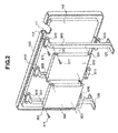
- Fig. 2 attached herewith shows a perspective view of the panel module 100, within the image displaying apparatus mentioned above, in particular, when only taking it out therefrom and seeing it from the rear side thereof.
- a part e. g.
- an outer side) of a flange portion 111 formed along an outer periphery of the frame, supporting that panel module 100 from the rear surface thereof, is further bent through a drawing or squeezing process, for example, into "U"-like shape in the cross-section thereof, as is shown in a partial cross-section thereof.
- a frame-like reinforcement portion 112 which is formed in the flange portion 111 the on an outer periphery of this frame 110 through the drawing or squeezing process, it is possible to maintain the mechanical strength thereof, simply or easily, without using an additional reinforcement member, within that panel module 100 after attaching the liquid crystal display (LCD) onto the frame 110.
- LCD liquid crystal display
- the structures for maintaining the mechanical strength of the panel module is advantageous for reducing the manufacturing cost, and it is advantageous, in particular, for the image displaying apparatus having the size less than 50 inches.
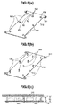
- the configuration of bending the part (e.g. , the outer side) of flange portion 111, which is formed along the outer periphery of the frame 110 should not be restricted only to the "U"-like shape mentioned above, and it may be in the configuration, for example, a semi-circular (see Fig. 3(a) ) or a triangle (see Fig. 3(b) ), in the cross-section thereof.
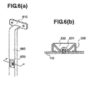
- the reinforcement structures for maintaining the mechanical strength of the panel module 100 should not be restricted only to the structures mentioned above, i.e., the reinforcement portion 112 of the "U"-like cross-section shape, which is formed on the outer periphery of the frame 110 through the drawing or squeezing process; but other than that, it is enough to be able to maintain the mechanical strength thereof, on the outer periphery of the frame 110 mentioned above (i.e., a frame-like reinforcement structure for the frame), and for example, as is shown in Fig.
- each of the supporting members 600 is formed with fixing portions 610 and 610, at upper and lower positions (2 positions) corresponding to the reinforcement portions 112, which are formed on the flange 111, on the outer periphery of the frame 110, in the longitudinal direction thereof (i.e., the vertical direction in the figure), to be fitted or inserted into gutters or grooves, which are formed in "U"-like shape in the cross-section thereof, and thereby to be fixed by means of screws 611 or the like.
- the fixing portions 610 and 610 which are formed at the upper and lower positions (2 positions) thereof, are fixed to the reinforcement portions 112 (i.e., the flange portions 111, with which are formed the frame-like reinforcement portions), being the reinforcement structures for maintaining the mechanical strength of the panel module 100, but not attached directly on the rear surface of the frame 110.
- the reinforcement portions 112 i.e., the flange portions 111, with which are formed the frame-like reinforcement portions
- the present invention should not be restricted only to this, and the two (2) pieces of the supporting members 600 and 600 at the both ends thereof may have the same structure of the supporting member 600 at the center thereof.
- the stand 120 mentioned above is fixed at a central power of the lower side of the panel module 100, with using the reinforcement portion 112, which is formed on the lower side thereof.
- the signal board 500 mentioned above, and further the power source board 510, etc. can be attached, within a narrow space remaining on the rear surface side of that panel module 100, with utilizing those plural pieces of the supporting members 600, 600..., with high efficiency.
- the signal board 500 and the power source board 510 are attached on the supporting members 600, 600..., respectively, with using holder portions 501 and 511, which are formed in part of that module (in the present example, at corner parts), by means of screws 611, etc., in the similar manner to the above, for example.
- a terminal board or substrate having a plural number of terminals for connecting that apparatus to an external equipment, to be separated from the signal board 500 mentioned above, as other unit (for example, a lower portion of the signal board 500), since it can be attached or removed, easily, dependent upon changes of the destination of that product, etc.
- Figs. 5 (a) to 5(c) attached herewith show the structures suitable for the signal board 500 and the power source board 510, to be attached with using the plural number of the supporting members 600, 600..., and in particular, the latter thereof, the power source board 510.
- an insulated substrate 512 building up this power source board 510 is formed with using an insulating paper or plate having flexibility, such as, NOMEX film or paper (®) produced by DuPont Corp. , etc. , for example, by cutting it out into about a rectangular shape in the outer configuration (see Figs. 5 (a) and 5 (b) ).
- NOMEX film or paper ®
- a plural number of flat head pins 520 and 530 are driven (or attached) at predetermined positions, respectively, from the surface thereof, so that, as is shown in Fig. 5(b) , the flat head pin 520 at the central portion and those 530 on both sides thereof project the tips thereof on the reverse side of the insulated substrate 512, penetrating the tips thereof through the substrate 512, and thereby they are used as spacers for maintaining a predetermined gap between the reverse surface of the frame 110.
- the projection heights of the flat head pins are so determined, the height "hc" of the flat head pin 520 at the central portion thereof is a little bit larger than the height "hs" (hc>hs) of the flat head pins 530 on both sides thereof.
- Fig. 5(c) On the insulated substrate 512 of the power source board 510, which is built up in the manner mentioned above, are formed elements (shown by broken lines in Fig. 5(c) ), building up power source circuits for supplying various kinds of voltage sources, on the reverse surface shown in Fig. 5(b) . And, that power source board 510 is disposed in a narrow space remaining on the reverse surface side of the panel module 100, with using the insulated substrate 512 and the supporting members 600, 600... In that instance, as is shown in Fig.
- the insulated substrate 512 (in particular, the elements shown by the broken lines, which are provided on the reverse surface thereof), is disposed at the position, separating from the reverse surface of the frame 110 of the panel module 100 by a predetermined distance, in particular, due to the function of the flat head pin 520 at the central portion, and further, in that instance, even if the insulated substrate 512 is suppressed and bent by a force applied from an outside, it can be still maintained at that position separating from the reverse surface of the frame 110 by the predetermined distance, due to the functions of the flat head pins 530 on both sides thereof.
- the insulated substrate 512 having the flat head pins 520 and 530 mentioned above, it is possible to maintain the predetermined distance necessary, between the elements building up those power source circuits and the frame 110, with certainty (i.e., preventing the elements from contacting on the frame). For that reason, such the structures can be preferably applied, in particular, as the insulated substrate within the power source board 510, having a possibility of generating an accident due to contacting of the panel module with the frame.
- Fig. 7 shows the state (or condition) where the rear cover 300 is attached on the reverse surface of the panel module, after attaching the circuit boards thereon, such as, the signal board and the power source board, etc., mentioned above, with using the plural pieces of the supporting members 600, 600..., which are attached on the reverse side of the panel module, in the manner as was mentioned above.
- the signal board 500 and the power source board 510 are, as apparent from the structures thereof mentioned above, since they are attached while defining gaps between the frame 110, on the rear surface side of the panel module, as is shown by arrows in the figure, the airs flowing into an inside of the rear cover 300 through openings 301, which are formed in a lower portion thereof, pass through the gaps mentioned above and also in vicinity of the elements, and thereby moving upwards while cooling down the signal board 500 and/or the power source board 510. Thereafter, they flow out into an outside from openings 302, 302..., which are formed in an upper portion of the rear cover 300.
- the circuit boards or substrates such as, the signal board 500 and/or the power source board 510, etc.
- the circuit boards or substrates can be disposed within the narrow space remaining on the reverse surface side of the panel module, with using the plural number of the supporting members, which are attached on the reverse side of the panel module, and also the cooling of those circuit boards can be ensured with certainty.
- the plural numbers of the supporting members 600, 600... which are mentioned above, are attached, aligning, preferably, into a flow of the airs cooling the signal board 500 and/or the power source board 510, i. e. , in the vertical direction.
Priority Applications (2)
| Application Number | Priority Date | Filing Date | Title |
|---|---|---|---|
| EP23197620.0A EP4270935A3 (fr) | 2007-09-28 | 2008-05-30 | Appareil d'affichage d'images |
| EP20198190.9A EP3787383B1 (fr) | 2007-09-28 | 2008-05-30 | Appareil d'affichage d'images |
Applications Claiming Priority (4)
| Application Number | Priority Date | Filing Date | Title |
|---|---|---|---|
| JP2007255752A JP5113468B2 (ja) | 2007-09-28 | 2007-09-28 | 画像表示装置 |
| JP2007255769A JP2009086276A (ja) | 2007-09-28 | 2007-09-28 | 画像表示装置とその支持体構造 |
| EP13171478.4A EP2651202B1 (fr) | 2007-09-28 | 2008-05-30 | Appareil d'affichage d'images |
| EP08251889.5A EP2043415B1 (fr) | 2007-09-28 | 2008-05-30 | Appareil d'affichage d'images |
Related Parent Applications (3)
| Application Number | Title | Priority Date | Filing Date |
|---|---|---|---|
| EP08251889.5A Division EP2043415B1 (fr) | 2007-09-28 | 2008-05-30 | Appareil d'affichage d'images |
| EP13171478.4A Division EP2651202B1 (fr) | 2007-09-28 | 2008-05-30 | Appareil d'affichage d'images |
| EP13171478.4A Division-Into EP2651202B1 (fr) | 2007-09-28 | 2008-05-30 | Appareil d'affichage d'images |
Related Child Applications (3)
| Application Number | Title | Priority Date | Filing Date |
|---|---|---|---|
| EP20198190.9A Division EP3787383B1 (fr) | 2007-09-28 | 2008-05-30 | Appareil d'affichage d'images |
| EP20198190.9A Division-Into EP3787383B1 (fr) | 2007-09-28 | 2008-05-30 | Appareil d'affichage d'images |
| EP23197620.0A Division EP4270935A3 (fr) | 2007-09-28 | 2008-05-30 | Appareil d'affichage d'images |
Publications (3)
| Publication Number | Publication Date |
|---|---|
| EP2988493A2 true EP2988493A2 (fr) | 2016-02-24 |
| EP2988493A3 EP2988493A3 (fr) | 2016-05-18 |
| EP2988493B1 EP2988493B1 (fr) | 2020-11-18 |
Family
ID=40153799
Family Applications (5)
| Application Number | Title | Priority Date | Filing Date |
|---|---|---|---|
| EP20198190.9A Active EP3787383B1 (fr) | 2007-09-28 | 2008-05-30 | Appareil d'affichage d'images |
| EP23197620.0A Pending EP4270935A3 (fr) | 2007-09-28 | 2008-05-30 | Appareil d'affichage d'images |
| EP08251889.5A Active EP2043415B1 (fr) | 2007-09-28 | 2008-05-30 | Appareil d'affichage d'images |
| EP13171478.4A Active EP2651202B1 (fr) | 2007-09-28 | 2008-05-30 | Appareil d'affichage d'images |
| EP15183447.0A Active EP2988493B1 (fr) | 2007-09-28 | 2008-05-30 | Appareil d'affichage d'images |
Family Applications Before (4)
| Application Number | Title | Priority Date | Filing Date |
|---|---|---|---|
| EP20198190.9A Active EP3787383B1 (fr) | 2007-09-28 | 2008-05-30 | Appareil d'affichage d'images |
| EP23197620.0A Pending EP4270935A3 (fr) | 2007-09-28 | 2008-05-30 | Appareil d'affichage d'images |
| EP08251889.5A Active EP2043415B1 (fr) | 2007-09-28 | 2008-05-30 | Appareil d'affichage d'images |
| EP13171478.4A Active EP2651202B1 (fr) | 2007-09-28 | 2008-05-30 | Appareil d'affichage d'images |
Country Status (3)
| Country | Link |
|---|---|
| US (4) | US7796206B2 (fr) |
| EP (5) | EP3787383B1 (fr) |
| CN (3) | CN101888759B (fr) |
Families Citing this family (15)
| Publication number | Priority date | Publication date | Assignee | Title |
|---|---|---|---|---|
| JP5259110B2 (ja) * | 2007-03-27 | 2013-08-07 | 三菱電機株式会社 | 表示装置 |
| US8325471B2 (en) * | 2007-11-15 | 2012-12-04 | Panasonic Corporation | Display device |
| JP5201964B2 (ja) * | 2007-12-03 | 2013-06-05 | 三洋電機株式会社 | 画像表示装置 |
| KR101569842B1 (ko) | 2009-09-30 | 2015-11-17 | 삼성전자 주식회사 | 텔레비전용 전원공급유닛 및 이를 포함하는 텔레비전 |
| JP2011081212A (ja) * | 2009-10-07 | 2011-04-21 | Fujitsu Ltd | 電子機器 |
| JP5263113B2 (ja) * | 2009-10-07 | 2013-08-14 | 富士通株式会社 | 電子機器 |
| JP2011081213A (ja) * | 2009-10-07 | 2011-04-21 | Fujitsu Ltd | 画像表示パネル、電子機器、および画像表示パネルの分解方法 |
| JP5218367B2 (ja) * | 2009-10-07 | 2013-06-26 | 富士通株式会社 | ケーブル配線構造および電子機器 |
| US9711752B2 (en) | 2011-12-19 | 2017-07-18 | Lg Electronics Inc. | Display apparatus |
| JP2014048381A (ja) * | 2012-08-30 | 2014-03-17 | Sony Corp | 表示装置 |
| TWM478848U (zh) * | 2013-06-21 | 2014-05-21 | Chi Mei Comm Systems Inc | 電子裝置 |
| CN203868632U (zh) * | 2014-05-29 | 2014-10-08 | 京东方科技集团股份有限公司 | 一种支撑装置、显示装置 |
| WO2016103620A1 (fr) * | 2014-12-26 | 2016-06-30 | パナソニックIpマネジメント株式会社 | Dispositif d'affichage et support |
| WO2016136218A1 (fr) * | 2015-02-23 | 2016-09-01 | パナソニックIpマネジメント株式会社 | Dispositif d'affichage et plaque arrière utilisée dans ledit dispositif d'affichage |
| CN110839103A (zh) * | 2018-08-17 | 2020-02-25 | 深圳富泰宏精密工业有限公司 | 电子装置及其控制方法 |
Citations (5)
| Publication number | Priority date | Publication date | Assignee | Title |
|---|---|---|---|---|
| JPH11109879A (ja) | 1997-08-04 | 1999-04-23 | Canon Inc | パネルを支持する支持構造、およびパネルと該パネルを支持する支持構造を有するパネル装置、および該パネル装置を用いた画像形成装置 |
| JP2001100650A (ja) | 1999-10-01 | 2001-04-13 | Hitachi Ltd | 情報表示装置 |
| JP2004021104A (ja) | 2002-06-19 | 2004-01-22 | Sharp Corp | 液晶表示装置 |
| JP2004151305A (ja) | 2002-10-30 | 2004-05-27 | Matsushita Electric Ind Co Ltd | プラズマディスプレイ装置 |
| JP2007159048A (ja) | 2005-12-08 | 2007-06-21 | Sony Corp | 画像表示装置 |
Family Cites Families (52)
| Publication number | Priority date | Publication date | Assignee | Title |
|---|---|---|---|---|
| JP3080718B2 (ja) | 1991-09-20 | 2000-08-28 | 日本電気株式会社 | 出力バッファ回路 |
| US5479285A (en) | 1993-09-01 | 1995-12-26 | Ncr Corporation | Liquid crystal device with an isotropic shock mounting and gasket |
| US5808707A (en) * | 1995-03-01 | 1998-09-15 | Canon Kabushiki Kaisha | Display apparatus |
| JPH09297543A (ja) | 1996-05-07 | 1997-11-18 | Kouha:Kk | 発光表示装置 |
| JP2898600B2 (ja) | 1996-05-07 | 1999-06-02 | 株式会社光波 | 発光表示装置 |
| US5836676A (en) | 1996-05-07 | 1998-11-17 | Koha Co., Ltd. | Light emitting display apparatus |
| JPH10172445A (ja) | 1996-12-06 | 1998-06-26 | Fujitsu General Ltd | Pdpの放熱構造 |
| JP2000137440A (ja) * | 1997-08-04 | 2000-05-16 | Canon Inc | 画像形成装置 |
| JP2000089682A (ja) | 1998-09-08 | 2000-03-31 | Matsushita Electric Ind Co Ltd | 映像表示装置 |
| JP4209524B2 (ja) | 1998-12-09 | 2009-01-14 | シチズンホールディングス株式会社 | 多層セル表示装置 |
| JP2000258754A (ja) | 1999-03-05 | 2000-09-22 | Kanazawa Chuo Hatsujo Kogyo Kk | 液晶パネル保持枠の製造方法 |
| JP2000285820A (ja) | 1999-03-31 | 2000-10-13 | Matsushita Electric Ind Co Ltd | シャドウマスク |
| JP2001022281A (ja) * | 1999-07-09 | 2001-01-26 | Matsushita Electric Ind Co Ltd | プラズマディスプレイ装置 |
| JP2001022280A (ja) | 1999-07-09 | 2001-01-26 | Matsushita Electric Ind Co Ltd | プラズマディスプレイ装置 |
| JP3773732B2 (ja) | 1999-12-28 | 2006-05-10 | 三菱電機株式会社 | 液晶表示装置及びこれを用いた電気・電子機器 |
| JP2001337611A (ja) * | 2000-03-22 | 2001-12-07 | Furukawa Electric Co Ltd:The | 表示装置のフレーム |
| JP4672123B2 (ja) | 2000-09-14 | 2011-04-20 | 東芝モバイルディスプレイ株式会社 | 平面表示装置用のバックライト |
| JP4130753B2 (ja) | 2002-08-22 | 2008-08-06 | 三星エスディアイ株式会社 | 衝撃緩和構造を有する有機電子発光表示装置 |
| JP2005017791A (ja) | 2003-06-27 | 2005-01-20 | Hitachi Displays Ltd | 表示装置 |
| JP4448296B2 (ja) | 2003-06-27 | 2010-04-07 | 株式会社ニューギン | 遊技機 |
| JP2005045703A (ja) * | 2003-07-25 | 2005-02-17 | Sony Corp | ディスプレイ装置 |
| JP4017617B2 (ja) * | 2003-09-10 | 2007-12-05 | シャープ株式会社 | 液晶表示装置 |
| JP4007340B2 (ja) | 2003-09-19 | 2007-11-14 | セイコーエプソン株式会社 | 電気光学装置、電子機器及び電気光学装置の製造方法 |
| TWI268526B (en) * | 2003-12-05 | 2006-12-11 | Au Optronics Corp | Plasma display |
| KR100542520B1 (ko) * | 2004-03-24 | 2006-01-11 | 삼성에스디아이 주식회사 | 플라즈마 디스플레이 장치 |
| JP2005284106A (ja) | 2004-03-30 | 2005-10-13 | Tama Fine Opto Co Ltd | バックライト装置および液晶表示装置並びに枠部材 |
| JP2005283505A (ja) | 2004-03-30 | 2005-10-13 | Miyota Kk | 時計の液晶セル支持構造 |
| KR100612278B1 (ko) * | 2004-05-18 | 2006-08-11 | 삼성에스디아이 주식회사 | 플라즈마 디스플레이 장치 |
| JP2005346932A (ja) | 2004-05-31 | 2005-12-15 | Citizen Electronics Co Ltd | バックライトユニットホルダ |
| JP4421963B2 (ja) * | 2004-07-15 | 2010-02-24 | Necインフロンティア株式会社 | 電子機器 |
| KR100647609B1 (ko) * | 2004-08-24 | 2006-11-23 | 삼성에스디아이 주식회사 | 새시 베이스용 모서리 보강재 및 이를 구비한 디스플레이모듈 |
| JP2006065119A (ja) | 2004-08-27 | 2006-03-09 | Pioneer Electronic Corp | フラット型表示装置 |
| US7573547B2 (en) | 2004-09-27 | 2009-08-11 | Idc, Llc | System and method for protecting micro-structure of display array using spacers in gap within display device |
| JP2006106618A (ja) * | 2004-10-08 | 2006-04-20 | Hitachi Ltd | 表示装置 |
| KR100669756B1 (ko) * | 2004-11-11 | 2007-01-16 | 삼성에스디아이 주식회사 | 플라즈마 표시장치 조립체 |
| KR100669779B1 (ko) * | 2004-11-22 | 2007-01-16 | 삼성에스디아이 주식회사 | 평판표시장치용 시일재 패턴 이를 구비한 평판표시장치 |
| JP2006162641A (ja) | 2004-12-02 | 2006-06-22 | Matsushita Electric Ind Co Ltd | プラズマ表示装置 |
| KR100670252B1 (ko) | 2004-12-17 | 2007-01-16 | 삼성에스디아이 주식회사 | 샤시 베이스 조립체와, 이를 제조하기 위한 방법과, 이를적용한 플라즈마 표시장치 조립체 |
| KR20060080409A (ko) * | 2005-01-05 | 2006-07-10 | 삼성에스디아이 주식회사 | 플라즈마 디스플레이 패널의 직부착 필터의 접지용브라켓의 장착방법 및 그 장착구조 |
| KR100626056B1 (ko) * | 2005-01-11 | 2006-09-21 | 삼성에스디아이 주식회사 | 플라즈마 디스플레이 장치 |
| JP3110945U (ja) * | 2005-03-02 | 2005-07-07 | 船井電機株式会社 | 液晶表示装置 |
| KR100637217B1 (ko) * | 2005-03-03 | 2006-10-23 | 삼성에스디아이 주식회사 | 플라즈마 디스플레이 장치 |
| KR101134302B1 (ko) | 2005-06-30 | 2012-04-13 | 엘지디스플레이 주식회사 | 액정표시장치용 커버버툼 및 이를 이용한 발광다이오드백라이트어셈블리와 액정표시장치모듈 |
| US20100134459A1 (en) * | 2005-07-12 | 2010-06-03 | Toyoshi Kawada | Flat display device |
| KR20070023271A (ko) | 2005-08-24 | 2007-02-28 | 삼성전자주식회사 | 표시 장치 및 이의 제조 방법 |
| JP2007065302A (ja) | 2005-08-31 | 2007-03-15 | Orion Denki Kk | 表示装置 |
| JP3117833U (ja) * | 2005-10-21 | 2006-01-12 | 船井電機株式会社 | パネル型テレビジョンおよび液晶テレビジョン |
| JP4210860B2 (ja) * | 2005-12-26 | 2009-01-21 | 船井電機株式会社 | パネル型テレビジョンおよび液晶テレビジョン |
| CN101160612B (zh) * | 2005-12-27 | 2010-05-19 | 松下电器产业株式会社 | 等离子显示装置 |
| KR100813726B1 (ko) * | 2005-12-30 | 2008-03-13 | 엘지전자 주식회사 | 디스플레이 기기의 스탠드 |
| KR100760770B1 (ko) * | 2006-03-29 | 2007-09-21 | 삼성에스디아이 주식회사 | 플라즈마 표시장치 |
| JP4857253B2 (ja) * | 2007-12-07 | 2012-01-18 | 株式会社日立製作所 | 画像表示装置 |
-
2008
- 2008-05-30 EP EP20198190.9A patent/EP3787383B1/fr active Active
- 2008-05-30 EP EP23197620.0A patent/EP4270935A3/fr active Pending
- 2008-05-30 EP EP08251889.5A patent/EP2043415B1/fr active Active
- 2008-05-30 EP EP13171478.4A patent/EP2651202B1/fr active Active
- 2008-05-30 EP EP15183447.0A patent/EP2988493B1/fr active Active
- 2008-06-23 CN CN2010102334969A patent/CN101888759B/zh active Active
- 2008-06-23 CN CN2010102335001A patent/CN101888760B/zh active Active
- 2008-06-23 CN CN201210297892.7A patent/CN102791098B/zh active Active
- 2008-06-30 US US12/164,215 patent/US7796206B2/en active Active
-
2010
- 2010-06-02 US US12/792,131 patent/US7924366B2/en active Active
- 2010-06-30 US US12/828,038 patent/US8023062B2/en active Active
-
2011
- 2011-08-03 US US13/197,398 patent/US8576350B2/en active Active
Patent Citations (5)
| Publication number | Priority date | Publication date | Assignee | Title |
|---|---|---|---|---|
| JPH11109879A (ja) | 1997-08-04 | 1999-04-23 | Canon Inc | パネルを支持する支持構造、およびパネルと該パネルを支持する支持構造を有するパネル装置、および該パネル装置を用いた画像形成装置 |
| JP2001100650A (ja) | 1999-10-01 | 2001-04-13 | Hitachi Ltd | 情報表示装置 |
| JP2004021104A (ja) | 2002-06-19 | 2004-01-22 | Sharp Corp | 液晶表示装置 |
| JP2004151305A (ja) | 2002-10-30 | 2004-05-27 | Matsushita Electric Ind Co Ltd | プラズマディスプレイ装置 |
| JP2007159048A (ja) | 2005-12-08 | 2007-06-21 | Sony Corp | 画像表示装置 |
Also Published As
| Publication number | Publication date |
|---|---|
| CN102791098A (zh) | 2012-11-21 |
| EP2988493A3 (fr) | 2016-05-18 |
| CN101888759A (zh) | 2010-11-17 |
| EP2651202A3 (fr) | 2013-11-20 |
| EP4270935A3 (fr) | 2024-01-24 |
| CN102791098B (zh) | 2015-07-22 |
| EP2651202A2 (fr) | 2013-10-16 |
| EP2043415A2 (fr) | 2009-04-01 |
| EP3787383B1 (fr) | 2023-10-18 |
| US20090086119A1 (en) | 2009-04-02 |
| EP2651202B1 (fr) | 2015-10-14 |
| US7796206B2 (en) | 2010-09-14 |
| EP2043415B1 (fr) | 2013-08-21 |
| EP4270935A2 (fr) | 2023-11-01 |
| EP2988493B1 (fr) | 2020-11-18 |
| US20100238372A1 (en) | 2010-09-23 |
| EP2043415A3 (fr) | 2010-12-29 |
| US20100271361A1 (en) | 2010-10-28 |
| US8576350B2 (en) | 2013-11-05 |
| EP3787383A1 (fr) | 2021-03-03 |
| US20110286169A1 (en) | 2011-11-24 |
| CN101888760B (zh) | 2012-10-10 |
| US8023062B2 (en) | 2011-09-20 |
| CN101888759B (zh) | 2012-12-19 |
| CN101888760A (zh) | 2010-11-17 |
| US7924366B2 (en) | 2011-04-12 |
Similar Documents
| Publication | Publication Date | Title |
|---|---|---|
| EP2988493B1 (fr) | Appareil d'affichage d'images | |
| US7206037B2 (en) | Display module and display unit | |
| US7234945B2 (en) | Display apparatus | |
| US7525627B2 (en) | Display device | |
| US20130141664A1 (en) | Liquid crystal display device | |
| CN101398542A (zh) | 图像显示装置 | |
| US6639636B2 (en) | Liquid crystal display of direct lighting type | |
| JP4305564B2 (ja) | 画像表示装置とその支持体構造 | |
| JP5113468B2 (ja) | 画像表示装置 | |
| KR100741132B1 (ko) | 플라즈마 디스플레이 장치 | |
| KR100421915B1 (ko) | 액정표시장치의 하부커버 결합구조 | |
| KR101350972B1 (ko) | 백라이트 유닛과 이를 포함하는 액정표시장치모듈 | |
| KR101014481B1 (ko) | 액정표시장치의 모듈 | |
| JP5097851B2 (ja) | 薄型表示装置用の電源基板及びそれを用いた薄型表示装置 | |
| KR101046975B1 (ko) | 플라즈마 디스플레이 장치 |
Legal Events
| Date | Code | Title | Description |
|---|---|---|---|
| PUAI | Public reference made under article 153(3) epc to a published international application that has entered the european phase |
Free format text: ORIGINAL CODE: 0009012 |
|
| 17P | Request for examination filed |
Effective date: 20150918 |
|
| AC | Divisional application: reference to earlier application |
Ref document number: 2651202 Country of ref document: EP Kind code of ref document: P Ref document number: 2043415 Country of ref document: EP Kind code of ref document: P |
|
| AK | Designated contracting states |
Kind code of ref document: A2 Designated state(s): AT BE BG CH CY CZ DE DK EE ES FI FR GB GR HR HU IE IS IT LI LT LU LV MC MT NL NO PL PT RO SE SI SK TR |
|
| PUAL | Search report despatched |
Free format text: ORIGINAL CODE: 0009013 |
|
| AK | Designated contracting states |
Kind code of ref document: A3 Designated state(s): AT BE BG CH CY CZ DE DK EE ES FI FR GB GR HR HU IE IS IT LI LT LU LV MC MT NL NO PL PT RO SE SI SK TR |
|
| RIC1 | Information provided on ipc code assigned before grant |
Ipc: H05K 5/02 20060101ALI20160408BHEP Ipc: H05K 5/00 20060101ALI20160408BHEP Ipc: G09F 9/00 20060101ALI20160408BHEP Ipc: H05K 1/14 20060101ALI20160408BHEP Ipc: H04N 5/64 20060101AFI20160408BHEP |
|
| RAP1 | Party data changed (applicant data changed or rights of an application transferred) |
Owner name: MAXELL, LTD. |
|
| STAA | Information on the status of an ep patent application or granted ep patent |
Free format text: STATUS: EXAMINATION IS IN PROGRESS |
|
| 17Q | First examination report despatched |
Effective date: 20181113 |
|
| GRAP | Despatch of communication of intention to grant a patent |
Free format text: ORIGINAL CODE: EPIDOSNIGR1 |
|
| STAA | Information on the status of an ep patent application or granted ep patent |
Free format text: STATUS: GRANT OF PATENT IS INTENDED |
|
| INTG | Intention to grant announced |
Effective date: 20200603 |
|
| GRAS | Grant fee paid |
Free format text: ORIGINAL CODE: EPIDOSNIGR3 |
|
| GRAA | (expected) grant |
Free format text: ORIGINAL CODE: 0009210 |
|
| STAA | Information on the status of an ep patent application or granted ep patent |
Free format text: STATUS: THE PATENT HAS BEEN GRANTED |
|
| AC | Divisional application: reference to earlier application |
Ref document number: 2043415 Country of ref document: EP Kind code of ref document: P Ref document number: 2651202 Country of ref document: EP Kind code of ref document: P |
|
| AK | Designated contracting states |
Kind code of ref document: B1 Designated state(s): AT BE BG CH CY CZ DE DK EE ES FI FR GB GR HR HU IE IS IT LI LT LU LV MC MT NL NO PL PT RO SE SI SK TR |
|
| REG | Reference to a national code |
Ref country code: GB Ref legal event code: FG4D |
|
| REG | Reference to a national code |
Ref country code: CH Ref legal event code: EP |
|
| REG | Reference to a national code |
Ref country code: IE Ref legal event code: FG4D |
|
| REG | Reference to a national code |
Ref country code: DE Ref legal event code: R096 Ref document number: 602008063482 Country of ref document: DE |
|
| REG | Reference to a national code |
Ref country code: AT Ref legal event code: REF Ref document number: 1337019 Country of ref document: AT Kind code of ref document: T Effective date: 20201215 |
|
| REG | Reference to a national code |
Ref country code: AT Ref legal event code: MK05 Ref document number: 1337019 Country of ref document: AT Kind code of ref document: T Effective date: 20201118 |
|
| REG | Reference to a national code |
Ref country code: NL Ref legal event code: MP Effective date: 20201118 |
|
| PG25 | Lapsed in a contracting state [announced via postgrant information from national office to epo] |
Ref country code: GR Free format text: LAPSE BECAUSE OF FAILURE TO SUBMIT A TRANSLATION OF THE DESCRIPTION OR TO PAY THE FEE WITHIN THE PRESCRIBED TIME-LIMIT Effective date: 20210219 Ref country code: FI Free format text: LAPSE BECAUSE OF FAILURE TO SUBMIT A TRANSLATION OF THE DESCRIPTION OR TO PAY THE FEE WITHIN THE PRESCRIBED TIME-LIMIT Effective date: 20201118 Ref country code: PT Free format text: LAPSE BECAUSE OF FAILURE TO SUBMIT A TRANSLATION OF THE DESCRIPTION OR TO PAY THE FEE WITHIN THE PRESCRIBED TIME-LIMIT Effective date: 20210318 Ref country code: NO Free format text: LAPSE BECAUSE OF FAILURE TO SUBMIT A TRANSLATION OF THE DESCRIPTION OR TO PAY THE FEE WITHIN THE PRESCRIBED TIME-LIMIT Effective date: 20210218 |
|
| PG25 | Lapsed in a contracting state [announced via postgrant information from national office to epo] |
Ref country code: LV Free format text: LAPSE BECAUSE OF FAILURE TO SUBMIT A TRANSLATION OF THE DESCRIPTION OR TO PAY THE FEE WITHIN THE PRESCRIBED TIME-LIMIT Effective date: 20201118 Ref country code: IS Free format text: LAPSE BECAUSE OF FAILURE TO SUBMIT A TRANSLATION OF THE DESCRIPTION OR TO PAY THE FEE WITHIN THE PRESCRIBED TIME-LIMIT Effective date: 20210318 Ref country code: PL Free format text: LAPSE BECAUSE OF FAILURE TO SUBMIT A TRANSLATION OF THE DESCRIPTION OR TO PAY THE FEE WITHIN THE PRESCRIBED TIME-LIMIT Effective date: 20201118 Ref country code: SE Free format text: LAPSE BECAUSE OF FAILURE TO SUBMIT A TRANSLATION OF THE DESCRIPTION OR TO PAY THE FEE WITHIN THE PRESCRIBED TIME-LIMIT Effective date: 20201118 Ref country code: BG Free format text: LAPSE BECAUSE OF FAILURE TO SUBMIT A TRANSLATION OF THE DESCRIPTION OR TO PAY THE FEE WITHIN THE PRESCRIBED TIME-LIMIT Effective date: 20210218 Ref country code: AT Free format text: LAPSE BECAUSE OF FAILURE TO SUBMIT A TRANSLATION OF THE DESCRIPTION OR TO PAY THE FEE WITHIN THE PRESCRIBED TIME-LIMIT Effective date: 20201118 |
|
| REG | Reference to a national code |
Ref country code: LT Ref legal event code: MG9D |
|
| PG25 | Lapsed in a contracting state [announced via postgrant information from national office to epo] |
Ref country code: HR Free format text: LAPSE BECAUSE OF FAILURE TO SUBMIT A TRANSLATION OF THE DESCRIPTION OR TO PAY THE FEE WITHIN THE PRESCRIBED TIME-LIMIT Effective date: 20201118 |
|
| PG25 | Lapsed in a contracting state [announced via postgrant information from national office to epo] |
Ref country code: SK Free format text: LAPSE BECAUSE OF FAILURE TO SUBMIT A TRANSLATION OF THE DESCRIPTION OR TO PAY THE FEE WITHIN THE PRESCRIBED TIME-LIMIT Effective date: 20201118 Ref country code: RO Free format text: LAPSE BECAUSE OF FAILURE TO SUBMIT A TRANSLATION OF THE DESCRIPTION OR TO PAY THE FEE WITHIN THE PRESCRIBED TIME-LIMIT Effective date: 20201118 Ref country code: LT Free format text: LAPSE BECAUSE OF FAILURE TO SUBMIT A TRANSLATION OF THE DESCRIPTION OR TO PAY THE FEE WITHIN THE PRESCRIBED TIME-LIMIT Effective date: 20201118 Ref country code: EE Free format text: LAPSE BECAUSE OF FAILURE TO SUBMIT A TRANSLATION OF THE DESCRIPTION OR TO PAY THE FEE WITHIN THE PRESCRIBED TIME-LIMIT Effective date: 20201118 Ref country code: CZ Free format text: LAPSE BECAUSE OF FAILURE TO SUBMIT A TRANSLATION OF THE DESCRIPTION OR TO PAY THE FEE WITHIN THE PRESCRIBED TIME-LIMIT Effective date: 20201118 |
|
| REG | Reference to a national code |
Ref country code: DE Ref legal event code: R097 Ref document number: 602008063482 Country of ref document: DE |
|
| PG25 | Lapsed in a contracting state [announced via postgrant information from national office to epo] |
Ref country code: DK Free format text: LAPSE BECAUSE OF FAILURE TO SUBMIT A TRANSLATION OF THE DESCRIPTION OR TO PAY THE FEE WITHIN THE PRESCRIBED TIME-LIMIT Effective date: 20201118 |
|
| PLBE | No opposition filed within time limit |
Free format text: ORIGINAL CODE: 0009261 |
|
| STAA | Information on the status of an ep patent application or granted ep patent |
Free format text: STATUS: NO OPPOSITION FILED WITHIN TIME LIMIT |
|
| 26N | No opposition filed |
Effective date: 20210819 |
|
| PG25 | Lapsed in a contracting state [announced via postgrant information from national office to epo] |
Ref country code: NL Free format text: LAPSE BECAUSE OF FAILURE TO SUBMIT A TRANSLATION OF THE DESCRIPTION OR TO PAY THE FEE WITHIN THE PRESCRIBED TIME-LIMIT Effective date: 20201118 Ref country code: IT Free format text: LAPSE BECAUSE OF FAILURE TO SUBMIT A TRANSLATION OF THE DESCRIPTION OR TO PAY THE FEE WITHIN THE PRESCRIBED TIME-LIMIT Effective date: 20201118 |
|
| PG25 | Lapsed in a contracting state [announced via postgrant information from national office to epo] |
Ref country code: ES Free format text: LAPSE BECAUSE OF FAILURE TO SUBMIT A TRANSLATION OF THE DESCRIPTION OR TO PAY THE FEE WITHIN THE PRESCRIBED TIME-LIMIT Effective date: 20201118 Ref country code: SI Free format text: LAPSE BECAUSE OF FAILURE TO SUBMIT A TRANSLATION OF THE DESCRIPTION OR TO PAY THE FEE WITHIN THE PRESCRIBED TIME-LIMIT Effective date: 20201118 |
|
| REG | Reference to a national code |
Ref country code: CH Ref legal event code: PL |
|
| PG25 | Lapsed in a contracting state [announced via postgrant information from national office to epo] |
Ref country code: LU Free format text: LAPSE BECAUSE OF NON-PAYMENT OF DUE FEES Effective date: 20210530 Ref country code: LI Free format text: LAPSE BECAUSE OF NON-PAYMENT OF DUE FEES Effective date: 20210531 Ref country code: MC Free format text: LAPSE BECAUSE OF FAILURE TO SUBMIT A TRANSLATION OF THE DESCRIPTION OR TO PAY THE FEE WITHIN THE PRESCRIBED TIME-LIMIT Effective date: 20201118 Ref country code: CH Free format text: LAPSE BECAUSE OF NON-PAYMENT OF DUE FEES Effective date: 20210531 |
|
| REG | Reference to a national code |
Ref country code: BE Ref legal event code: MM Effective date: 20210531 |
|
| PG25 | Lapsed in a contracting state [announced via postgrant information from national office to epo] |
Ref country code: IE Free format text: LAPSE BECAUSE OF NON-PAYMENT OF DUE FEES Effective date: 20210530 |
|
| PG25 | Lapsed in a contracting state [announced via postgrant information from national office to epo] |
Ref country code: IS Free format text: LAPSE BECAUSE OF FAILURE TO SUBMIT A TRANSLATION OF THE DESCRIPTION OR TO PAY THE FEE WITHIN THE PRESCRIBED TIME-LIMIT Effective date: 20210318 |
|
| PG25 | Lapsed in a contracting state [announced via postgrant information from national office to epo] |
Ref country code: BE Free format text: LAPSE BECAUSE OF NON-PAYMENT OF DUE FEES Effective date: 20210531 |
|
| REG | Reference to a national code |
Ref country code: GB Ref legal event code: 732E Free format text: REGISTERED BETWEEN 20220728 AND 20220803 |
|
| REG | Reference to a national code |
Ref country code: DE Ref legal event code: R081 Ref document number: 602008063482 Country of ref document: DE Owner name: MAXELL, LTD., OYAMAZAKI, JP Free format text: FORMER OWNER: MAXELL, LTD., KYOTO, JP |
|
| REG | Reference to a national code |
Ref country code: DE Ref legal event code: R081 Ref document number: 602008063482 Country of ref document: DE Owner name: MAXELL, LTD., OYAMAZAKI, JP Free format text: FORMER OWNER: MAXELL HOLDINGS, LTD., OYAMAZAKI, KYOTO, JP |
|
| PG25 | Lapsed in a contracting state [announced via postgrant information from national office to epo] |
Ref country code: HU Free format text: LAPSE BECAUSE OF FAILURE TO SUBMIT A TRANSLATION OF THE DESCRIPTION OR TO PAY THE FEE WITHIN THE PRESCRIBED TIME-LIMIT; INVALID AB INITIO Effective date: 20080530 Ref country code: CY Free format text: LAPSE BECAUSE OF FAILURE TO SUBMIT A TRANSLATION OF THE DESCRIPTION OR TO PAY THE FEE WITHIN THE PRESCRIBED TIME-LIMIT Effective date: 20201118 |
|
| PGFP | Annual fee paid to national office [announced via postgrant information from national office to epo] |
Ref country code: FR Payment date: 20230526 Year of fee payment: 16 Ref country code: DE Payment date: 20230519 Year of fee payment: 16 |
|
| PGFP | Annual fee paid to national office [announced via postgrant information from national office to epo] |
Ref country code: GB Payment date: 20230524 Year of fee payment: 16 |