EP2980479B1 - Gas internal combustion engine gas leak checking device and method for same - Google Patents
Gas internal combustion engine gas leak checking device and method for same Download PDFInfo
- Publication number
- EP2980479B1 EP2980479B1 EP14775095.4A EP14775095A EP2980479B1 EP 2980479 B1 EP2980479 B1 EP 2980479B1 EP 14775095 A EP14775095 A EP 14775095A EP 2980479 B1 EP2980479 B1 EP 2980479B1
- Authority
- EP
- European Patent Office
- Prior art keywords
- gas
- safety shutoff
- shutoff valve
- fuel
- valve
- Prior art date
- Legal status (The legal status is an assumption and is not a legal conclusion. Google has not performed a legal analysis and makes no representation as to the accuracy of the status listed.)
- Active
Links
- 238000002485 combustion reaction Methods 0.000 title claims description 44
- 238000000034 method Methods 0.000 title claims description 12
- 239000007789 gas Substances 0.000 claims description 120
- 239000002737 fuel gas Substances 0.000 claims description 110
- 238000011144 upstream manufacturing Methods 0.000 claims description 7
- MWUXSHHQAYIFBG-UHFFFAOYSA-N Nitric oxide Chemical compound O=[N] MWUXSHHQAYIFBG-UHFFFAOYSA-N 0.000 description 6
- 238000010586 diagram Methods 0.000 description 5
- 239000000446 fuel Substances 0.000 description 5
- QGZKDVFQNNGYKY-UHFFFAOYSA-N Ammonia Chemical compound N QGZKDVFQNNGYKY-UHFFFAOYSA-N 0.000 description 4
- 230000007423 decrease Effects 0.000 description 4
- 230000002159 abnormal effect Effects 0.000 description 3
- 238000010926 purge Methods 0.000 description 3
- IJGRMHOSHXDMSA-UHFFFAOYSA-N Atomic nitrogen Chemical compound N#N IJGRMHOSHXDMSA-UHFFFAOYSA-N 0.000 description 2
- 239000004215 Carbon black (E152) Substances 0.000 description 2
- UGFAIRIUMAVXCW-UHFFFAOYSA-N Carbon monoxide Chemical compound [O+]#[C-] UGFAIRIUMAVXCW-UHFFFAOYSA-N 0.000 description 2
- 229910002091 carbon monoxide Inorganic materials 0.000 description 2
- 239000003054 catalyst Substances 0.000 description 2
- 238000001514 detection method Methods 0.000 description 2
- 238000007599 discharging Methods 0.000 description 2
- 230000000694 effects Effects 0.000 description 2
- 229930195733 hydrocarbon Natural products 0.000 description 2
- 150000002430 hydrocarbons Chemical class 0.000 description 2
- 238000000746 purification Methods 0.000 description 2
- 229910021529 ammonia Inorganic materials 0.000 description 1
- 238000007664 blowing Methods 0.000 description 1
- 238000007796 conventional method Methods 0.000 description 1
- 238000001816 cooling Methods 0.000 description 1
- 230000001186 cumulative effect Effects 0.000 description 1
- 239000000428 dust Substances 0.000 description 1
- 230000005489 elastic deformation Effects 0.000 description 1
- 238000009434 installation Methods 0.000 description 1
- 238000005461 lubrication Methods 0.000 description 1
- 239000000463 material Substances 0.000 description 1
- 229910052757 nitrogen Inorganic materials 0.000 description 1
- 229910000069 nitrogen hydride Inorganic materials 0.000 description 1
- 230000003647 oxidation Effects 0.000 description 1
- 238000007254 oxidation reaction Methods 0.000 description 1
- 230000001590 oxidative effect Effects 0.000 description 1
- 239000013618 particulate matter Substances 0.000 description 1
- 230000002265 prevention Effects 0.000 description 1
- XLYOFNOQVPJJNP-UHFFFAOYSA-N water Substances O XLYOFNOQVPJJNP-UHFFFAOYSA-N 0.000 description 1
Images


Classifications
-
- G—PHYSICS
- G01—MEASURING; TESTING
- G01M—TESTING STATIC OR DYNAMIC BALANCE OF MACHINES OR STRUCTURES; TESTING OF STRUCTURES OR APPARATUS, NOT OTHERWISE PROVIDED FOR
- G01M3/00—Investigating fluid-tightness of structures
- G01M3/02—Investigating fluid-tightness of structures by using fluid or vacuum
- G01M3/025—Details with respect to the testing of engines or engine parts
-
- F—MECHANICAL ENGINEERING; LIGHTING; HEATING; WEAPONS; BLASTING
- F02—COMBUSTION ENGINES; HOT-GAS OR COMBUSTION-PRODUCT ENGINE PLANTS
- F02D—CONTROLLING COMBUSTION ENGINES
- F02D19/00—Controlling engines characterised by their use of non-liquid fuels, pluralities of fuels, or non-fuel substances added to the combustible mixtures
- F02D19/02—Controlling engines characterised by their use of non-liquid fuels, pluralities of fuels, or non-fuel substances added to the combustible mixtures peculiar to engines working with gaseous fuels
- F02D19/025—Failure diagnosis or prevention; Safety measures; Testing
-
- F—MECHANICAL ENGINEERING; LIGHTING; HEATING; WEAPONS; BLASTING
- F02—COMBUSTION ENGINES; HOT-GAS OR COMBUSTION-PRODUCT ENGINE PLANTS
- F02D—CONTROLLING COMBUSTION ENGINES
- F02D19/00—Controlling engines characterised by their use of non-liquid fuels, pluralities of fuels, or non-fuel substances added to the combustible mixtures
- F02D19/02—Controlling engines characterised by their use of non-liquid fuels, pluralities of fuels, or non-fuel substances added to the combustible mixtures peculiar to engines working with gaseous fuels
- F02D19/026—Measuring or estimating parameters related to the fuel supply system
- F02D19/027—Determining the fuel pressure, temperature or volume flow, the fuel tank fill level or a valve position
-
- F—MECHANICAL ENGINEERING; LIGHTING; HEATING; WEAPONS; BLASTING
- F02—COMBUSTION ENGINES; HOT-GAS OR COMBUSTION-PRODUCT ENGINE PLANTS
- F02M—SUPPLYING COMBUSTION ENGINES IN GENERAL WITH COMBUSTIBLE MIXTURES OR CONSTITUENTS THEREOF
- F02M21/00—Apparatus for supplying engines with non-liquid fuels, e.g. gaseous fuels stored in liquid form
- F02M21/02—Apparatus for supplying engines with non-liquid fuels, e.g. gaseous fuels stored in liquid form for gaseous fuels
- F02M21/0218—Details on the gaseous fuel supply system, e.g. tanks, valves, pipes, pumps, rails, injectors or mixers
- F02M21/023—Valves; Pressure or flow regulators in the fuel supply or return system
- F02M21/0242—Shut-off valves; Check valves; Safety valves; Pressure relief valves
-
- F—MECHANICAL ENGINEERING; LIGHTING; HEATING; WEAPONS; BLASTING
- F02—COMBUSTION ENGINES; HOT-GAS OR COMBUSTION-PRODUCT ENGINE PLANTS
- F02M—SUPPLYING COMBUSTION ENGINES IN GENERAL WITH COMBUSTIBLE MIXTURES OR CONSTITUENTS THEREOF
- F02M21/00—Apparatus for supplying engines with non-liquid fuels, e.g. gaseous fuels stored in liquid form
- F02M21/02—Apparatus for supplying engines with non-liquid fuels, e.g. gaseous fuels stored in liquid form for gaseous fuels
- F02M21/0218—Details on the gaseous fuel supply system, e.g. tanks, valves, pipes, pumps, rails, injectors or mixers
- F02M21/0293—Safety devices; Fail-safe measures
-
- F—MECHANICAL ENGINEERING; LIGHTING; HEATING; WEAPONS; BLASTING
- F23—COMBUSTION APPARATUS; COMBUSTION PROCESSES
- F23K—FEEDING FUEL TO COMBUSTION APPARATUS
- F23K5/00—Feeding or distributing other fuel to combustion apparatus
- F23K5/002—Gaseous fuel
- F23K5/007—Details
-
- F—MECHANICAL ENGINEERING; LIGHTING; HEATING; WEAPONS; BLASTING
- F23—COMBUSTION APPARATUS; COMBUSTION PROCESSES
- F23N—REGULATING OR CONTROLLING COMBUSTION
- F23N5/00—Systems for controlling combustion
- F23N5/24—Preventing development of abnormal or undesired conditions, i.e. safety arrangements
- F23N5/242—Preventing development of abnormal or undesired conditions, i.e. safety arrangements using electronic means
-
- G—PHYSICS
- G01—MEASURING; TESTING
- G01M—TESTING STATIC OR DYNAMIC BALANCE OF MACHINES OR STRUCTURES; TESTING OF STRUCTURES OR APPARATUS, NOT OTHERWISE PROVIDED FOR
- G01M15/00—Testing of engines
- G01M15/04—Testing internal-combustion engines
- G01M15/09—Testing internal-combustion engines by monitoring pressure in fluid ducts, e.g. in lubrication or cooling parts
-
- F—MECHANICAL ENGINEERING; LIGHTING; HEATING; WEAPONS; BLASTING
- F23—COMBUSTION APPARATUS; COMBUSTION PROCESSES
- F23K—FEEDING FUEL TO COMBUSTION APPARATUS
- F23K2900/00—Special features of, or arrangements for fuel supplies
- F23K2900/05001—Control or safety devices in gaseous or liquid fuel supply lines
-
- F—MECHANICAL ENGINEERING; LIGHTING; HEATING; WEAPONS; BLASTING
- F23—COMBUSTION APPARATUS; COMBUSTION PROCESSES
- F23N—REGULATING OR CONTROLLING COMBUSTION
- F23N2231/00—Fail safe
- F23N2231/18—Detecting fluid leaks
-
- Y—GENERAL TAGGING OF NEW TECHNOLOGICAL DEVELOPMENTS; GENERAL TAGGING OF CROSS-SECTIONAL TECHNOLOGIES SPANNING OVER SEVERAL SECTIONS OF THE IPC; TECHNICAL SUBJECTS COVERED BY FORMER USPC CROSS-REFERENCE ART COLLECTIONS [XRACs] AND DIGESTS
- Y02—TECHNOLOGIES OR APPLICATIONS FOR MITIGATION OR ADAPTATION AGAINST CLIMATE CHANGE
- Y02T—CLIMATE CHANGE MITIGATION TECHNOLOGIES RELATED TO TRANSPORTATION
- Y02T10/00—Road transport of goods or passengers
- Y02T10/10—Internal combustion engine [ICE] based vehicles
- Y02T10/30—Use of alternative fuels, e.g. biofuels
Definitions
- the present invention relates to a gas leakage checking device and a method for the same, for checking leakage of safety shutoff valves in a fuel-gas supply circuit before startup of a precombustion-chamber type lean premixed gas internal combustion engine.
- a gas engine In a precombustion-chamber type lean premixed gas internal combustion engine (hereinafter, referred to as a gas engine), to secure supply and safety of the fuel gas, a variety of devices, valves, and the like are provided.
- Unpredictable leakage of the fuel gas may occur from the above devices, valves, and the like.
- Fuel gas having leaked from the above devices, valves, and the like may flow to and accumulate in each of the gas engine, an exhaust channel, and the like.
- the gas engine If the gas engine is ignited and started under such a condition, the accumulating fuel gas undergoes abnormal combustion and damages the gas engine, the exhaust channel, and the like.
- Patent Document 1 discloses a gas leakage checking device.
- a gas supply pipe 07 for supplying fuel gas to a gas burner 05 includes the first and second on-off valves 081, 082 disposed in series, and a proportional electromagnetic valve 09 disposed on the downstream side of the first and second on-off valves 081, 082.
- the above first and second on-off valves 081, 082 open when supplied with power, and close when not supplied with power due to a biasing force of a spring so as to shut off supply of fuel gas to the gas burner 05.
- the proportional electromagnetic valve 09 adjusts the amount of fuel gas supply to the gas burner 05.
- the gas burner 05 includes a spark electrode 010a that discharges sparks as an igniter 010 operates, and a thermocouple 011 serving as a flame-detection element for detecting flame of the gas burner 05.
- a controller 013 which controls operation of a fan motor 03a for driving a fan 03, the first and second on-off valves 081, 082, the proportional electromagnetic valve 09, the igniter 010, and the like.
- the proportional electromagnetic valve 09 is maintained to be opened for a predetermined period of time or more when an operation switch is turned off, the rotation speed of the fan 03 is reduced to the lower-limit rotation speed within the normal operation range, and the igniter 010 is started.
- first on-off valve 081 is opened, and the second on-off valve 082 is closed.
- first on-off valve 081 is closed, and the second on-off valve 082 is opened.
- the first on-off valve 081 is closed, and the second on-off valve 082 is opened.
- the first on-off valve 081 is opened, and the second on-off valve 082 is closed.
- Patent Document 1 JP2010-270948A
- concentration of the fuel gas with respect to air needs to be in a certain range.
- the present invention was made in view of the above issues, and an object of the present invention is to provide a gas leakage checking device and a method for the same, for checking fuel-gas leakage of safety shutoff valves simply and securely by measuring a pressure in a fuel supply pipe.
- the present invention can provide a gas-leakage checking device for a gas internal combustion engine, including: a fuel-gas supply pipe for supplying fuel gas to a combustion chamber of the gas internal combustion engine; a first safety shutoff valve disposed in the fuel-gas supply pipe for permitting or shutting off a flow of the fuel gas; a second safety shutoff valve disposed in the fuel-gas supply pipe on a downstream side of the first safety shutoff valve at a distance from the first safety shutoff valve; a gas-leakage checking pipe branched from the fuel-gas supply pipe between the first safety shutoff valve and the second safety shutoff valve; a gas-discharge valve disposed in the gas-leakage checking pipe and configured to discharge the fuel gas between the first safety shutoff valve and the second safety shutoff valve; a first pressure meter disposed on an upstream side of the gas-discharge valve and configured to detect a pressure of the fuel gas; and a second pressure meter disposed on a downstream side of the second safety shutoff valve and configured
- the pressure between the first and second safety shutoff valves and the pressure at the downstream side of the second safety shutoff valve are detected, which makes it possible to check a trouble of the first and second safety shutoff valves and the gas-charge valve, and to improve the reliability of the gas engine.
- the gas leakage checking device may further include: a control device configured to open and close the first safety shutoff valve, the second safety shutoff valve, and the gas-discharge valve in a set order; and a starting switch for starting the control device.
- the control device is configured to operate, on the basis of operation of the starting switch, a first operation unit for checking fuel-gas leakage of the first safety shutoff valve, a second operation unit for checking the fuel-gas leakage of the second safety shutoff valve and the gas-discharge valve, and a third operation unit for checking the fuel-gas leakage of the first safety shutoff valve, the second safety shutoff valve, and the gas-discharge valve, in sequence.
- the control device on the basis of operation of a starting switch, operates each safety valve and the gas-discharge valve on the basis of a set procedure, which makes it possible to prevent check errors and the like due to operational errors and to improve reliability upon startup of the gas engine.
- control device since the control device is started using a manual switch, the startup can be performed optionally, which makes it possible to improve reliability of the gas engine.
- the gas internal combustion engine is a gas internal combustion engine
- the fuel-gas supply pipe being branched at a downstream side of the second safety shutoff valve into a main-chamber supply pipe for supplying the fuel gas to a main chamber of the combustion chamber and a precombustion-chamber supply pipe for supplying the fuel gas to a precombustion chamber of the combustion chamber
- the second pressure meter including a main pressure meter and an auxiliary pressure meter.
- the main-chamber supply pipe includes a main pressure-adjustment valve for adjusting the pressure of the fuel gas supplied to the main chamber, the main pressure meter being disposed on a downstream side of the main pressure-adjustment valve.
- the precombustion-chamber supply pipe includes an auxiliary pressure-adjustment valve for adjusting the pressure of the fuel gas supplied to the precombustion chamber, the auxiliary pressure meter being disposed on a downstream side of the auxiliary pressure-adjustment valve.
- the main pressure meter and the auxiliary pressure meter are used as pressure meters by the pressure-adjustment valves for adjusting a pressure of fuel gas that is to be supplied to the main chamber and the precombustion chamber of the combustion chamber, and for checking leakage of the fuel gas at the second safety shutoff valve.
- a method of checking gas leakage of a gas internal combustion engine which includes: a fuel-gas supply pipe for supplying fuel gas to a combustion chamber of the gas internal combustion engine; a first safety shutoff valve disposed in the fuel-gas supply pipe; a second safety shutoff valve disposed on a downstream side of the first safety shutoff valve at a distance from the first safety shutoff valve; a gas-discharge valve disposed between the first safety shutoff valve and the second safety shutoff valve and configured to discharge the fuel gas between the first safety shutoff valve and the second safety shutoff valve; a first pressure meter disposed on an upstream side of the gas-discharge valve and configured to detect a pressure of the fuel gas; and a second pressure meter disposed on a downstream side of the second safety shutoff valve and configured to detect the pressure of the fuel gas in the fuel-gas supply pipe.
- the method includes: a first operation step of checking fuel-gas leakage of the first safety shutoff valve by operating the gas-discharge valve from an open state to a closed state and maintaining the first and second safety shutoff valves to be in a closed state; a second operation step of checking the fuel-gas leakage of the second safety shutoff valve and the gas-discharge valve by operating the first safety shutoff valve from a closed state to an open state and maintaining the second safety shutoff valve and the gas-discharge valve to be in a closed state; and a third operation step of checking the fuel-gas leakage of the first safety shutoff valve, the second safety shutoff valve, and the gas-discharge valve by operating the first safety shutoff valve from an open state to a closed state and maintaining the second safety shutoff valve and the gas-discharge valve to be in a closed state.
- the first operation step, the second operation step, and the third operation step are performed in response to operation to switch on a starting switch for starting a control device configured to open and close the first safety shutoff valve, the second safety shutoff valve, and the gas-discharge valve on the basis of a set order.
- double cross check is performed to determine leakage of gas fuel of the first safety shutoff valve, the second safety shutoff valve, and the gas-discharge valve disposed in the fuel supply circuit of the gas internal combustion engine.
- non-combusted gas is prevented from accumulating in the gas engine and the exhaust channel when the gas engine is restarted after shutdown, which makes it possible to prevent abnormal combustion thereof.
- a gas leakage checking device of a gas internal combustion engine and a method for the same, for checking fuel-gas leakage of safety shutoff valves simply and securely by measuring a pressure in a fuel supply pipe.
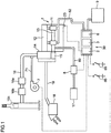
- FIG. 1 With reference to FIG. 1 , the overall configuration of a precombustion-chamber type lean premixed gas internal combustion engine (hereinafter, referred to in short as a gas engine) implementing the present invention will be described.
- a gas engine a precombustion-chamber type lean premixed gas internal combustion engine
- the gas engine 1 includes: an air starting device 30 coupled to the gas engine 1 via the first pipe 62; a compressed-air tank 9 for supplying compressed air to the air starting device 30; a turbocharger 14 mounted to an exhaust-air collecting pipe 12 of the gas engine 1; an exhaust channel 16 for discharging to the atmosphere exhaust gas having driven an exhaust turbine (not illustrated) of the turbocharger 14; an air cleaner 18 for removing dust contained in air that is to be supplied to the gas engine 1; an air cooler 15 coupled coaxially to the exhaust turbine for compressing supply air from the air cleaner 18 and cooling heated supply air; a fan and motor 7 for exhaust purge coupled to the exhaust channel 16 at the downstream side of the turbocharger 14 in the flow direction of exhaust gas via a blower pipe 71, for blowing air into the exhaust channel 16; a fuel-gas supply device 17 for supplying fuel gas to the gas engine 1; and a gas-leakage checking device 8 disposed in a fuel-gas supply pipe 89 disposed between the fuel-gas supply device 17 and a supply-air pipe
- an oxidation catalyst 16b for oxidizing and detoxifying carbon monoxide (CO) and hydrocarbon (HC) contained in the exhaust gas, a denitration device 16c for decomposing nitrogen oxide (NOx) contained in the exhaust gas into harmless nitrogen and water by injecting ammonia (NH3) and using a catalyst so as to obtain clean exhaust gas, a PM filter 16a for removing suspended particulate matters contained in the exhaust gas (PM: particulate matter), and the like are disposed in accordance with the required specification of the device.
- the channel capacity of the exhaust channel 16 varies depending on the required specification of the exhaust-gas purification device to be mounted.
- 23 is a rotation-speed sensor for measuring the cumulative rotation speed of slow-air turning upon startup of the gas engine.
- the air starting device 30 includes a control device 2 for controlling operation of the air starting device 30, a main air-starting unit 6 which increases the gas engine 1 to a rotation speed for startup of fuel-gas ignition operation, and a compressed-air supply unit 3 for performing slow-air turning for checking the inside of each cylinder of the gas engine 1 and securing lubrication between cylinders and pistons in the cylinders before operation of the main air-starting unit 6.
- control device 2 is a comprehensive control device which controls the air starting device 30, the fan and motor 7 for exhaust purge and the gas-leakage checking device 8.
- the main air starting unit 6 introduces compressed air supplied from the main air starting unit 6 into each cylinder in accordance with an order of the ignition timing of the gas engine 1, and increases the gas engine 1 to the rotation speed for starting fuel-gas ignition operation with the pressure of the compressed air.
- leakage may occur from devices for gas-fuel supply and safety.
- non-combusted gas may accumulate in the exhaust channel 16 due to a failure in ignition upon startup, for instance.
- the compressed air used by the air starting device 30 may discharge the non-combusted gas in the gas engine 1 and the exhaust channel 16.
- the non-combusted gas may not be discharged adequately by the compressed air from the air starting device 30.
- the gas-leakage checking device 8 disposed in the fuel-gas supply pipe 89 is manually started.
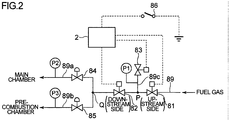
- the gas-leakage checking device 8 is disposed in the fuel-gas supply pipe 89 connecting the fuel-gas supply device 17 and the supply-air pipe 13.
- the gas-leakage checking device 8 includes: the first safety shutoff valve 81; the second safety shutoff valve 82 disposed on the downstream side of the first safety shutoff valve 81 at a distance from the first safety shutoff valve 81; a gas-leakage checking pipe 89c branched from the fuel-gas supply pipe 89 at an intermediate point P between the first safety shutoff valve 81 and the second safety shutoff valve 82; a gas-discharge valve 83 for discharging to the atmosphere or shutting off fuel gas between the first safety shutoff valve 81 and the second safety shutoff valve 82, disposed on a distal end portion of the gas-leakage checking pipe 89c; the first pressure meter P1 disposed in the gas-leakage checking pipe 89c between the point P and the gas-discharge valve 83; a main-chamber supply pipe 89a for introducing fuel gas to the main chamber of the combustion chamber at a point Q on the downstream side of the second safety shutoff valve 82; a precombustion
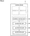
- control device 2 includes a control starting part 25, the first operation unit 24, the second operation unit 28, and the third operation unit 26.
- the control starting part 25 starts the control device 2 when the gas leakage checking S/W 86 is turned on.
- the first operation unit 24 checks leakage of fuel gas of the first safety shutoff valve by closing only the gas-discharge valve 83 in a state where the first and second safety shutoff valves 81, 82 are closed and the gas-discharge valve 83 is open.
- the second operation unit 28 checks leakage of fuel gas of the second safety shutoff valve 82 and the gas-discharge valve 83 by maintaining the second safety shutoff valve 82 and the gas-discharge valve 83 to be closed and opening the first safety shutoff valve 81, in a state of the first operation unit 24.
- the third operation unit 26 checks leakage of fuel gas of the first safety shutoff valve 81, the second safety shutoff valve 82, and the gas-discharge valve 83 by maintaining the second safety shutoff valve 82 and the gas-discharge valve 83 to be closed and closing the first safety shutoff valve 81 from an opened state.
- the gas-leakage checking S/W (switch) 86 of the gas-leakage checking device 8 is switched on manually.
- the control device 2 operates the gas-discharge valve 83 from an open state to a closed state in the first operation step (automatically operated by the control device 2) illustrated in FIG. 3 .
- the gas engine 1 maintains the gas-discharge valve 83 to be open during shutdown so that the fuel gas does not leak into the gas engine 1.
- the first safety shutoff valve 81 and the second safety shutoff valve 82 are both in a closed state.
- the pressure between the first safety shutoff valve 81 and the second safety shutoff valve 82 is the atmospheric pressure.
- first pressure meter P1 shows a pressure increase
- second and third pressure meters P2, P3 show no change, it means that gas is leaking at the first safety shutoff valve 81 (marked as ⁇ ), and gas is not leaking at the second safety shutoff valve 82.
- gas leakage of the gas-discharge valve 83 cannot be determined at this point of time because the pressure of the first pressure meter P1 increases when the amount of leakage is small with respect to the amount of gas leakage of the first safety shutoff valve 81.
- the pressures of the first, second, and third pressure meters P1, P2, P3 all increase.
- the first safety shutoff valve 81 is operated from a closed state to an open state.
- the fuel-gas pressure at the upstream side of the first pressure meter P1 is applied to the first pressure meter P1, and thus the pressure of the first pressure meter P1 increases. If the second and third pressure meters P2, P3 show no change, the second safety shutoff valve 82 and the gas-discharge valve 83 are determined to be not having gas leakage.
- the reading (pressure) of the first pressure meter P1 is a gas supply pressure.
- the first safety shutoff valve 81 is operated from an open state to a closed state.
- the first safety shutoff valve 81 and the gas-discharge valve 83 are shut off (no gas leakage) and the second safety shutoff valve 82 has gas leakage.
- pressure meters are provided to check gas leakage according to the above procedure so that double or triple cross check is performed to determine gas leakage of the first and second safety shutoff valves 81, 82 and the gas-discharge valve 83, which makes it possible to prevent in advance an unpredictable trouble due to gas leakage.
- the gas leakage checking S/W 86 serving as a starting switch starts the control device 2 to open and close each of the first safety shutoff valve 81, the second safety shutoff valve 82, and the gas-discharge valve 83 in a set order.
- a similar effect can be achieved by manually performing the operation steps 1 to 3 on each of the first safety shutoff valve 81, the second safety shutoff valve 82, and the gas-discharge valve 83.
- leakage of fuel gas is checked by double cross check for the first safety shutoff valve 81, the second safety shutoff valve 82, and the gas-discharge valve 83, which makes it possible to detect whether non-combusted gas is accumulating in the gas engine 1 and the exhaust channel 16 after the gas engine is halted and then restarted by ignition, thereby providing a starting device for a gas internal combustion engine whereby it is possible to improve safety, breakage prevention and durability and reliability of the gas engine 1 are improved.
- the present invention is suitably applied to a starting device for a gas internal combustion engine equipped with a slow air turning device that is operated before startup of an internal combustion engine including an air starting device.
Landscapes
- Engineering & Computer Science (AREA)
- Chemical & Material Sciences (AREA)
- Combustion & Propulsion (AREA)
- Mechanical Engineering (AREA)
- General Engineering & Computer Science (AREA)
- Oil, Petroleum & Natural Gas (AREA)
- Chemical Kinetics & Catalysis (AREA)
- General Chemical & Material Sciences (AREA)
- General Physics & Mathematics (AREA)
- Physics & Mathematics (AREA)
- Health & Medical Sciences (AREA)
- Biomedical Technology (AREA)
- Output Control And Ontrol Of Special Type Engine (AREA)
Applications Claiming Priority (2)
| Application Number | Priority Date | Filing Date | Title |
|---|---|---|---|
| JP2013073839A JP6071703B2 (ja) | 2013-03-29 | 2013-03-29 | ガス内燃機関のガス漏チェック装置とその方法 |
| PCT/JP2014/053832 WO2014156376A1 (ja) | 2013-03-29 | 2014-02-19 | ガス内燃機関のガス漏れチェック装置とその方法 |
Publications (3)
| Publication Number | Publication Date |
|---|---|
| EP2980479A1 EP2980479A1 (en) | 2016-02-03 |
| EP2980479A4 EP2980479A4 (en) | 2016-03-30 |
| EP2980479B1 true EP2980479B1 (en) | 2017-03-29 |
Family
ID=51623377
Family Applications (1)
| Application Number | Title | Priority Date | Filing Date |
|---|---|---|---|
| EP14775095.4A Active EP2980479B1 (en) | 2013-03-29 | 2014-02-19 | Gas internal combustion engine gas leak checking device and method for same |
Country Status (5)
| Country | Link |
|---|---|
| US (1) | US9816891B2 (zh) |
| EP (1) | EP2980479B1 (zh) |
| JP (1) | JP6071703B2 (zh) |
| CN (1) | CN105026839B (zh) |
| WO (1) | WO2014156376A1 (zh) |
Families Citing this family (14)
| Publication number | Priority date | Publication date | Assignee | Title |
|---|---|---|---|---|
| JP6071703B2 (ja) | 2013-03-29 | 2017-02-01 | 三菱重工業株式会社 | ガス内燃機関のガス漏チェック装置とその方法 |
| JP6420633B2 (ja) * | 2014-11-13 | 2018-11-07 | 新日鐵住金株式会社 | 可燃性ガス供給装置 |
| CN104502024A (zh) * | 2014-12-19 | 2015-04-08 | 中国石油天然气股份有限公司 | 阀门内漏流量量化回归预测方法及装置 |
| US20170082076A1 (en) * | 2015-09-17 | 2017-03-23 | Caterpillar Inc. | Pressure regulator for fuel supply system |
| CN105465818A (zh) * | 2015-12-29 | 2016-04-06 | 中国石油化工股份有限公司 | 燃烧炉用燃料系统安全切断阀泄漏监测装置 |
| JP6531747B2 (ja) * | 2016-11-16 | 2019-06-19 | トヨタ自動車株式会社 | 燃料ガス貯蔵供給システム |
| US11280213B2 (en) * | 2017-04-19 | 2022-03-22 | General Electric Company | Fluid supply line leakage detection system and method |
| KR101881312B1 (ko) * | 2017-05-22 | 2018-08-24 | 강대해 | 대량생산 가능형 친환경 그라인더 |
| KR102334411B1 (ko) | 2017-07-25 | 2021-12-03 | 삼성디스플레이 주식회사 | 디스플레이 장치 및 그 제조방법 |
| DE102017215886A1 (de) * | 2017-09-08 | 2019-03-14 | Man Diesel & Turbo Se | Mehrmotorenanlage |
| JP2019173643A (ja) * | 2018-03-28 | 2019-10-10 | 株式会社Ihi | 燃料供給装置及びガスタービン |
| CN112572846A (zh) * | 2020-11-23 | 2021-03-30 | 蓝箭航天技术有限公司 | 一种点火装置的试验方法和系统 |
| EP4108988A1 (en) | 2021-06-24 | 2022-12-28 | BDR Thermea Group B.V. | Method and mechanism for controlling the operation of a boiler |
| US11739716B2 (en) | 2021-09-01 | 2023-08-29 | American CNG, LLC | Supplemental fuel system for compression-ignition engine |
Family Cites Families (32)
| Publication number | Priority date | Publication date | Assignee | Title |
|---|---|---|---|---|
| JPS6013134B2 (ja) * | 1976-11-26 | 1985-04-05 | コロナ株式会社 | 燃料遮断弁漏洩検査方法 |
| JPH02179437A (ja) | 1988-12-29 | 1990-07-12 | Yamatake Honeywell Co Ltd | 二重遮断ガスバルブのリークチェック方法 |
| JPH02179435A (ja) | 1988-12-29 | 1990-07-12 | Yamatake Honeywell Co Ltd | 二重遮断ガスバルブのリークチェック装置 |
| JP2631597B2 (ja) * | 1992-04-10 | 1997-07-16 | 川崎重工業株式会社 | ガス燃料の燃焼制御方法 |
| JP3194619B2 (ja) | 1992-05-21 | 2001-07-30 | ヤンマーディーゼル株式会社 | 6bガス用副室式ガス機関 |
| JP3242239B2 (ja) * | 1993-11-24 | 2001-12-25 | バブコック日立株式会社 | 燃料ガス制御方法および装置 |
| US5649818A (en) * | 1996-03-04 | 1997-07-22 | Banner Engineering & Sales, Inc. | Gas oven burner control method and apparatus |
| JP3500846B2 (ja) * | 1996-03-08 | 2004-02-23 | スズキ株式会社 | 気体燃料の漏れ検出装置 |
| US5827950A (en) * | 1997-04-14 | 1998-10-27 | Woodbury Leak Advisor Co. | Leak test system |
| JP2000274311A (ja) * | 1999-03-19 | 2000-10-03 | Honda Motor Co Ltd | 車両用ガス燃料供給システム |
| JP2000282956A (ja) * | 1999-03-29 | 2000-10-10 | Honda Motor Co Ltd | 車両用ガス燃料供給システム |
| JP2000303909A (ja) * | 1999-04-22 | 2000-10-31 | Honda Motor Co Ltd | 車両用ガス燃料供給システム |
| JP3432458B2 (ja) | 1999-07-30 | 2003-08-04 | 富士通テン株式会社 | ガス燃料用内燃機関のガス漏れ検知及びフェイルセーフ制御方法及びその装置 |
| JP3949348B2 (ja) * | 2000-04-20 | 2007-07-25 | 本田技研工業株式会社 | ガス燃料供給装置 |
| JP4287989B2 (ja) * | 2000-06-29 | 2009-07-01 | 三菱重工業株式会社 | ガスタービン燃料供給装置の異常検知方法 |
| US6892712B2 (en) * | 2001-09-11 | 2005-05-17 | Denso Corporation | Leak check for fuel vapor purge system |
| JP2004177275A (ja) * | 2002-11-27 | 2004-06-24 | Toyota Motor Corp | リークテスト方法およびリークテスト装置 |
| JP4284702B2 (ja) * | 2004-07-05 | 2009-06-24 | 三浦工業株式会社 | ガス漏れ検出装置 |
| DE102004040706B4 (de) | 2004-08-19 | 2010-05-06 | Audi Ag | Verfahren zur Diagnose des Kraftstoffversorgungssystems einer Brennkraftmaschine |
| JP2008026016A (ja) * | 2006-07-18 | 2008-02-07 | Toyota Motor Corp | 漏洩検査装置及び漏洩検査方法 |
| JP5055164B2 (ja) * | 2008-02-29 | 2012-10-24 | 三菱重工業株式会社 | 副室式ガスエンジン及び発電設備 |
| JP5248269B2 (ja) | 2008-10-31 | 2013-07-31 | 株式会社東芝 | 遮断器の開閉制御装置、及び遮断器の開閉制御システム |
| JP5381180B2 (ja) | 2009-03-10 | 2014-01-08 | 富士ゼロックス株式会社 | 面発光型半導体レーザ、面発光型半導体レーザ装置、光送信装置および情報処理装置 |
| JP5119201B2 (ja) * | 2009-05-20 | 2013-01-16 | リンナイ株式会社 | ガス燃焼装置 |
| DE102010031216B4 (de) * | 2009-09-18 | 2024-03-14 | Robert Bosch Gmbh | Verfahren zur Prüfung der Funktionsfähigkeit eines Tankabsperrventils einer Kraftstoff-Tankanlage |
| JP5013493B2 (ja) | 2010-03-04 | 2012-08-29 | オムロン株式会社 | バルブ制御システムおよびバルブ制御方法 |
| JP5425677B2 (ja) | 2010-03-19 | 2014-02-26 | 株式会社ケーヒン | 燃料供給システム及び遮断弁故障診断装置 |
| JP5314717B2 (ja) * | 2011-02-24 | 2013-10-16 | 三菱重工業株式会社 | 副室式火花点火ガスエンジン |
| JP5856384B2 (ja) | 2011-03-30 | 2016-02-09 | 株式会社ケーヒン | 燃料供給システム及び燃料噴射制御装置 |
| CH705182A1 (de) * | 2011-06-17 | 2012-12-31 | Alstom Technology Ltd | Verfahren zum Betreiben einer Brennstoffversorgung für eine Wärmekraftmaschine. |
| JP5321671B2 (ja) | 2011-11-08 | 2013-10-23 | Jfeスチール株式会社 | 強度と加工性の均一性に優れた高張力熱延鋼板およびその製造方法 |
| JP6071703B2 (ja) | 2013-03-29 | 2017-02-01 | 三菱重工業株式会社 | ガス内燃機関のガス漏チェック装置とその方法 |
-
2013
- 2013-03-29 JP JP2013073839A patent/JP6071703B2/ja active Active
-
2014
- 2014-02-19 US US14/779,949 patent/US9816891B2/en active Active
- 2014-02-19 WO PCT/JP2014/053832 patent/WO2014156376A1/ja active Application Filing
- 2014-02-19 CN CN201480012212.XA patent/CN105026839B/zh active Active
- 2014-02-19 EP EP14775095.4A patent/EP2980479B1/en active Active
Also Published As
| Publication number | Publication date |
|---|---|
| US20160061685A1 (en) | 2016-03-03 |
| CN105026839A (zh) | 2015-11-04 |
| EP2980479A4 (en) | 2016-03-30 |
| WO2014156376A1 (ja) | 2014-10-02 |
| JP2014199147A (ja) | 2014-10-23 |
| JP6071703B2 (ja) | 2017-02-01 |
| CN105026839B (zh) | 2017-06-09 |
| US9816891B2 (en) | 2017-11-14 |
| EP2980479A1 (en) | 2016-02-03 |
Similar Documents
| Publication | Publication Date | Title |
|---|---|---|
| EP2980479B1 (en) | Gas internal combustion engine gas leak checking device and method for same | |
| JP6045424B2 (ja) | ガス内燃機関の始動装置 | |
| US9003762B2 (en) | Turbine exhaust plume mitigation system | |
| WO2016031219A1 (ja) | ガスタービンエンジンシステム | |
| CN115898648A (zh) | 燃气轮机设备 | |
| US20100326057A1 (en) | Exhaust Gas Purification Device | |
| US9453778B2 (en) | Valve leak detecting method and combustion equipment | |
| US20140250857A1 (en) | Low-concentration methane gas oxidation system using exhaust heat from gas turbine engine | |
| CN106907245B (zh) | 燃料供应系统及控制燃气涡轮发动机中的超速事件的方法 | |
| EP2957756B1 (en) | Exhaust purge device for gas internal combustion engine | |
| US20110167782A1 (en) | Systems and apparatus for a fuel control assembly for use in a gas turbine engine | |
| JP2006132478A (ja) | 副室掃気装置を備えたパイロット着火式ガスエンジン | |
| JP3627578B2 (ja) | 気体燃料車の燃料漏検出装置 | |
| RU2426946C2 (ru) | Устройство автоматического контроля и управления газовой горелкой | |
| JP5592965B2 (ja) | 希薄燃料吸入ガスタービンの制御方法および制御装置 | |
| CN103797231B (zh) | 内燃机装置及操作方法 | |
| JP2014134158A (ja) | ガスエンジンの排気装置 | |
| JPH0684153U (ja) | 油遮断弁の燃料漏れ検出装置 |
Legal Events
| Date | Code | Title | Description |
|---|---|---|---|
| PUAI | Public reference made under article 153(3) epc to a published international application that has entered the european phase |
Free format text: ORIGINAL CODE: 0009012 |
|
| 17P | Request for examination filed |
Effective date: 20150918 |
|
| AK | Designated contracting states |
Kind code of ref document: A1 Designated state(s): AL AT BE BG CH CY CZ DE DK EE ES FI FR GB GR HR HU IE IS IT LI LT LU LV MC MK MT NL NO PL PT RO RS SE SI SK SM TR |
|
| AX | Request for extension of the european patent |
Extension state: BA ME |
|
| A4 | Supplementary search report drawn up and despatched |
Effective date: 20160229 |
|
| RIC1 | Information provided on ipc code assigned before grant |
Ipc: F02D 19/02 20060101ALI20160223BHEP Ipc: F02M 21/02 20060101ALI20160223BHEP Ipc: F23N 5/24 20060101AFI20160223BHEP Ipc: F02D 41/00 20060101ALI20160223BHEP Ipc: F23K 5/00 20060101ALI20160223BHEP |
|
| DAX | Request for extension of the european patent (deleted) | ||
| GRAP | Despatch of communication of intention to grant a patent |
Free format text: ORIGINAL CODE: EPIDOSNIGR1 |
|
| INTG | Intention to grant announced |
Effective date: 20160908 |
|
| GRAS | Grant fee paid |
Free format text: ORIGINAL CODE: EPIDOSNIGR3 |
|
| GRAA | (expected) grant |
Free format text: ORIGINAL CODE: 0009210 |
|
| AK | Designated contracting states |
Kind code of ref document: B1 Designated state(s): AL AT BE BG CH CY CZ DE DK EE ES FI FR GB GR HR HU IE IS IT LI LT LU LV MC MK MT NL NO PL PT RO RS SE SI SK SM TR |
|
| REG | Reference to a national code |
Ref country code: GB Ref legal event code: FG4D |
|
| REG | Reference to a national code |
Ref country code: CH Ref legal event code: EP |
|
| REG | Reference to a national code |
Ref country code: AT Ref legal event code: REF Ref document number: 880143 Country of ref document: AT Kind code of ref document: T Effective date: 20170415 |
|
| REG | Reference to a national code |
Ref country code: IE Ref legal event code: FG4D |
|
| REG | Reference to a national code |
Ref country code: DE Ref legal event code: R096 Ref document number: 602014008164 Country of ref document: DE |
|
| PG25 | Lapsed in a contracting state [announced via postgrant information from national office to epo] |
Ref country code: NO Free format text: LAPSE BECAUSE OF FAILURE TO SUBMIT A TRANSLATION OF THE DESCRIPTION OR TO PAY THE FEE WITHIN THE PRESCRIBED TIME-LIMIT Effective date: 20170629 Ref country code: FI Free format text: LAPSE BECAUSE OF FAILURE TO SUBMIT A TRANSLATION OF THE DESCRIPTION OR TO PAY THE FEE WITHIN THE PRESCRIBED TIME-LIMIT Effective date: 20170329 Ref country code: LT Free format text: LAPSE BECAUSE OF FAILURE TO SUBMIT A TRANSLATION OF THE DESCRIPTION OR TO PAY THE FEE WITHIN THE PRESCRIBED TIME-LIMIT Effective date: 20170329 Ref country code: GR Free format text: LAPSE BECAUSE OF FAILURE TO SUBMIT A TRANSLATION OF THE DESCRIPTION OR TO PAY THE FEE WITHIN THE PRESCRIBED TIME-LIMIT Effective date: 20170630 Ref country code: HR Free format text: LAPSE BECAUSE OF FAILURE TO SUBMIT A TRANSLATION OF THE DESCRIPTION OR TO PAY THE FEE WITHIN THE PRESCRIBED TIME-LIMIT Effective date: 20170329 |
|
| REG | Reference to a national code |
Ref country code: NL Ref legal event code: MP Effective date: 20170329 |
|
| PG25 | Lapsed in a contracting state [announced via postgrant information from national office to epo] |
Ref country code: RS Free format text: LAPSE BECAUSE OF FAILURE TO SUBMIT A TRANSLATION OF THE DESCRIPTION OR TO PAY THE FEE WITHIN THE PRESCRIBED TIME-LIMIT Effective date: 20170329 Ref country code: LV Free format text: LAPSE BECAUSE OF FAILURE TO SUBMIT A TRANSLATION OF THE DESCRIPTION OR TO PAY THE FEE WITHIN THE PRESCRIBED TIME-LIMIT Effective date: 20170329 Ref country code: BG Free format text: LAPSE BECAUSE OF FAILURE TO SUBMIT A TRANSLATION OF THE DESCRIPTION OR TO PAY THE FEE WITHIN THE PRESCRIBED TIME-LIMIT Effective date: 20170629 Ref country code: SE Free format text: LAPSE BECAUSE OF FAILURE TO SUBMIT A TRANSLATION OF THE DESCRIPTION OR TO PAY THE FEE WITHIN THE PRESCRIBED TIME-LIMIT Effective date: 20170329 |
|
| PG25 | Lapsed in a contracting state [announced via postgrant information from national office to epo] |
Ref country code: NL Free format text: LAPSE BECAUSE OF FAILURE TO SUBMIT A TRANSLATION OF THE DESCRIPTION OR TO PAY THE FEE WITHIN THE PRESCRIBED TIME-LIMIT Effective date: 20170329 |
|
| PG25 | Lapsed in a contracting state [announced via postgrant information from national office to epo] |
Ref country code: CZ Free format text: LAPSE BECAUSE OF FAILURE TO SUBMIT A TRANSLATION OF THE DESCRIPTION OR TO PAY THE FEE WITHIN THE PRESCRIBED TIME-LIMIT Effective date: 20170329 Ref country code: EE Free format text: LAPSE BECAUSE OF FAILURE TO SUBMIT A TRANSLATION OF THE DESCRIPTION OR TO PAY THE FEE WITHIN THE PRESCRIBED TIME-LIMIT Effective date: 20170329 Ref country code: ES Free format text: LAPSE BECAUSE OF FAILURE TO SUBMIT A TRANSLATION OF THE DESCRIPTION OR TO PAY THE FEE WITHIN THE PRESCRIBED TIME-LIMIT Effective date: 20170329 Ref country code: RO Free format text: LAPSE BECAUSE OF FAILURE TO SUBMIT A TRANSLATION OF THE DESCRIPTION OR TO PAY THE FEE WITHIN THE PRESCRIBED TIME-LIMIT Effective date: 20170329 Ref country code: SK Free format text: LAPSE BECAUSE OF FAILURE TO SUBMIT A TRANSLATION OF THE DESCRIPTION OR TO PAY THE FEE WITHIN THE PRESCRIBED TIME-LIMIT Effective date: 20170329 |
|
| PG25 | Lapsed in a contracting state [announced via postgrant information from national office to epo] |
Ref country code: SM Free format text: LAPSE BECAUSE OF FAILURE TO SUBMIT A TRANSLATION OF THE DESCRIPTION OR TO PAY THE FEE WITHIN THE PRESCRIBED TIME-LIMIT Effective date: 20170329 Ref country code: IS Free format text: LAPSE BECAUSE OF FAILURE TO SUBMIT A TRANSLATION OF THE DESCRIPTION OR TO PAY THE FEE WITHIN THE PRESCRIBED TIME-LIMIT Effective date: 20170729 Ref country code: PL Free format text: LAPSE BECAUSE OF FAILURE TO SUBMIT A TRANSLATION OF THE DESCRIPTION OR TO PAY THE FEE WITHIN THE PRESCRIBED TIME-LIMIT Effective date: 20170329 |
|
| REG | Reference to a national code |
Ref country code: DE Ref legal event code: R097 Ref document number: 602014008164 Country of ref document: DE |
|
| PG25 | Lapsed in a contracting state [announced via postgrant information from national office to epo] |
Ref country code: DK Free format text: LAPSE BECAUSE OF FAILURE TO SUBMIT A TRANSLATION OF THE DESCRIPTION OR TO PAY THE FEE WITHIN THE PRESCRIBED TIME-LIMIT Effective date: 20170329 |
|
| PLBE | No opposition filed within time limit |
Free format text: ORIGINAL CODE: 0009261 |
|
| STAA | Information on the status of an ep patent application or granted ep patent |
Free format text: STATUS: NO OPPOSITION FILED WITHIN TIME LIMIT |
|
| PG25 | Lapsed in a contracting state [announced via postgrant information from national office to epo] |
Ref country code: IT Free format text: LAPSE BECAUSE OF FAILURE TO SUBMIT A TRANSLATION OF THE DESCRIPTION OR TO PAY THE FEE WITHIN THE PRESCRIBED TIME-LIMIT Effective date: 20170329 |
|
| 26N | No opposition filed |
Effective date: 20180103 |
|
| PG25 | Lapsed in a contracting state [announced via postgrant information from national office to epo] |
Ref country code: SI Free format text: LAPSE BECAUSE OF FAILURE TO SUBMIT A TRANSLATION OF THE DESCRIPTION OR TO PAY THE FEE WITHIN THE PRESCRIBED TIME-LIMIT Effective date: 20170329 |
|
| REG | Reference to a national code |
Ref country code: DE Ref legal event code: R082 Ref document number: 602014008164 Country of ref document: DE Representative=s name: HOFFMANN - EITLE PATENT- UND RECHTSANWAELTE PA, DE Ref country code: DE Ref legal event code: R081 Ref document number: 602014008164 Country of ref document: DE Owner name: MITSUBISHI HEAVY INDUSTRIES ENGINE & TURBOCHAR, JP Free format text: FORMER OWNER: MITSUBISHI HEAVY INDUSTRIES, LTD., TOKYO, JP |
|
| REG | Reference to a national code |
Ref country code: CH Ref legal event code: PL |
|
| PG25 | Lapsed in a contracting state [announced via postgrant information from national office to epo] |
Ref country code: MC Free format text: LAPSE BECAUSE OF FAILURE TO SUBMIT A TRANSLATION OF THE DESCRIPTION OR TO PAY THE FEE WITHIN THE PRESCRIBED TIME-LIMIT Effective date: 20170329 |
|
| GBPC | Gb: european patent ceased through non-payment of renewal fee |
Effective date: 20180219 |
|
| REG | Reference to a national code |
Ref country code: IE Ref legal event code: MM4A |
|
| REG | Reference to a national code |
Ref country code: BE Ref legal event code: MM Effective date: 20180228 |
|
| PG25 | Lapsed in a contracting state [announced via postgrant information from national office to epo] |
Ref country code: LI Free format text: LAPSE BECAUSE OF NON-PAYMENT OF DUE FEES Effective date: 20180228 Ref country code: CH Free format text: LAPSE BECAUSE OF NON-PAYMENT OF DUE FEES Effective date: 20180228 Ref country code: LU Free format text: LAPSE BECAUSE OF NON-PAYMENT OF DUE FEES Effective date: 20180219 |
|
| REG | Reference to a national code |
Ref country code: FR Ref legal event code: ST Effective date: 20181031 |
|
| REG | Reference to a national code |
Ref country code: AT Ref legal event code: PC Ref document number: 880143 Country of ref document: AT Kind code of ref document: T Owner name: MITSUBISHI HEAVY INDUSTRIES ENGINE & TURBOCHAR, JP Effective date: 20181019 |
|
| PG25 | Lapsed in a contracting state [announced via postgrant information from national office to epo] |
Ref country code: IE Free format text: LAPSE BECAUSE OF NON-PAYMENT OF DUE FEES Effective date: 20180219 |
|
| PG25 | Lapsed in a contracting state [announced via postgrant information from national office to epo] |
Ref country code: GB Free format text: LAPSE BECAUSE OF NON-PAYMENT OF DUE FEES Effective date: 20180219 Ref country code: BE Free format text: LAPSE BECAUSE OF NON-PAYMENT OF DUE FEES Effective date: 20180228 Ref country code: FR Free format text: LAPSE BECAUSE OF NON-PAYMENT OF DUE FEES Effective date: 20180228 |
|
| REG | Reference to a national code |
Ref country code: AT Ref legal event code: UEP Ref document number: 880143 Country of ref document: AT Kind code of ref document: T Effective date: 20170329 |
|
| PG25 | Lapsed in a contracting state [announced via postgrant information from national office to epo] |
Ref country code: MT Free format text: LAPSE BECAUSE OF NON-PAYMENT OF DUE FEES Effective date: 20180219 |
|
| PG25 | Lapsed in a contracting state [announced via postgrant information from national office to epo] |
Ref country code: TR Free format text: LAPSE BECAUSE OF FAILURE TO SUBMIT A TRANSLATION OF THE DESCRIPTION OR TO PAY THE FEE WITHIN THE PRESCRIBED TIME-LIMIT Effective date: 20170329 |
|
| PG25 | Lapsed in a contracting state [announced via postgrant information from national office to epo] |
Ref country code: PT Free format text: LAPSE BECAUSE OF FAILURE TO SUBMIT A TRANSLATION OF THE DESCRIPTION OR TO PAY THE FEE WITHIN THE PRESCRIBED TIME-LIMIT Effective date: 20170329 |
|
| PG25 | Lapsed in a contracting state [announced via postgrant information from national office to epo] |
Ref country code: MK Free format text: LAPSE BECAUSE OF NON-PAYMENT OF DUE FEES Effective date: 20170329 Ref country code: CY Free format text: LAPSE BECAUSE OF FAILURE TO SUBMIT A TRANSLATION OF THE DESCRIPTION OR TO PAY THE FEE WITHIN THE PRESCRIBED TIME-LIMIT Effective date: 20170329 Ref country code: HU Free format text: LAPSE BECAUSE OF FAILURE TO SUBMIT A TRANSLATION OF THE DESCRIPTION OR TO PAY THE FEE WITHIN THE PRESCRIBED TIME-LIMIT; INVALID AB INITIO Effective date: 20140219 |
|
| PG25 | Lapsed in a contracting state [announced via postgrant information from national office to epo] |
Ref country code: AL Free format text: LAPSE BECAUSE OF FAILURE TO SUBMIT A TRANSLATION OF THE DESCRIPTION OR TO PAY THE FEE WITHIN THE PRESCRIBED TIME-LIMIT Effective date: 20170329 |
|
| PGFP | Annual fee paid to national office [announced via postgrant information from national office to epo] |
Ref country code: AT Payment date: 20240125 Year of fee payment: 11 |
|
| PGFP | Annual fee paid to national office [announced via postgrant information from national office to epo] |
Ref country code: DE Payment date: 20231228 Year of fee payment: 11 |