EP2977245A1 - Türe für ein kraftfahrzeug mit zusätzlicher aufbruchsicherung - Google Patents
Türe für ein kraftfahrzeug mit zusätzlicher aufbruchsicherung Download PDFInfo
- Publication number
- EP2977245A1 EP2977245A1 EP15001659.0A EP15001659A EP2977245A1 EP 2977245 A1 EP2977245 A1 EP 2977245A1 EP 15001659 A EP15001659 A EP 15001659A EP 2977245 A1 EP2977245 A1 EP 2977245A1
- Authority
- EP
- European Patent Office
- Prior art keywords
- door
- mooring point
- mooring
- cab
- securing
- Prior art date
- Legal status (The legal status is an assumption and is not a legal conclusion. Google has not performed a legal analysis and makes no representation as to the accuracy of the status listed.)
- Granted
Links
Images


Classifications
-
- B—PERFORMING OPERATIONS; TRANSPORTING
- B60—VEHICLES IN GENERAL
- B60J—WINDOWS, WINDSCREENS, NON-FIXED ROOFS, DOORS, OR SIMILAR DEVICES FOR VEHICLES; REMOVABLE EXTERNAL PROTECTIVE COVERINGS SPECIALLY ADAPTED FOR VEHICLES
- B60J5/00—Doors
- B60J5/04—Doors arranged at the vehicle sides
- B60J5/0412—Lower door structure
- B60J5/0413—Inner panel, e.g. characterised by carrying components
-
- B—PERFORMING OPERATIONS; TRANSPORTING
- B60—VEHICLES IN GENERAL
- B60R—VEHICLES, VEHICLE FITTINGS, OR VEHICLE PARTS, NOT OTHERWISE PROVIDED FOR
- B60R25/00—Fittings or systems for preventing or indicating unauthorised use or theft of vehicles
- B60R25/01—Fittings or systems for preventing or indicating unauthorised use or theft of vehicles operating on vehicle systems or fittings, e.g. on doors, seats or windscreens
-
- E—FIXED CONSTRUCTIONS
- E05—LOCKS; KEYS; WINDOW OR DOOR FITTINGS; SAFES
- E05B—LOCKS; ACCESSORIES THEREFOR; HANDCUFFS
- E05B83/00—Vehicle locks specially adapted for particular types of wing or vehicle
- E05B83/36—Locks for passenger or like doors
- E05B83/42—Locks for passenger or like doors for large commercial vehicles, e.g. trucks, construction vehicles or vehicles for mass transport
Definitions
- the invention relates to a door for a motor vehicle, in particular a cab of a commercial vehicle, preferably a truck.
- An object of the invention is to provide an alternative door security for a cab door in addition to the actual door lock, in particular an inexpensive door lock in addition to the actual door lock.
- the invention provides a door for a motor vehicle, preferably a cab of a commercial vehicle, in particular a truck.
- the door comprises a door lock for closing the door and a door inside, in particular a door inner lining.
- the door is characterized in particular by the fact that it has a mooring point for a securing element for securing the door expedient from inside against unauthorized breaking in addition to the door lock.
- the mooring is expediently located behind the inside of the door, wherein the inside of the door has a mark for locating the mooring.
- the mooring point is conveniently positioned behind the marker.
- the central axis of the mooring point extends at least almost horizontally, namely with a maximum deviation of +/- 15 °, +/- 10 ° or +/- 5 °.
- the center axis of the mooring point can hit the inside of the door at least approximately at right angles, namely with a maximum deviation of +/- 15 °, +/- 10 ° or +/- 5 °. This can be ensured in particular that the securing element easily finds the mooring point on the hole to be attached to the mark.
- the marking is mechanical, z. B. as a recess, and / or color.
- the mechanical marking can z. B. as a grain point or other depression (eg., Cross-shaped groove) may be formed so that the marking expediently at the same time facilitates the production of the hole for access to the mooring.
- the mooring point comprises an internal thread, in particular a nut with internal thread.
- the nut is preferably a weld nut welded to the door support structure.
- the securing element preferably has an external thread.
- the fuse element can, for. B. be a ring or hook part, preferably with collar, which is expedient fastened to the mooring.
- the ring part can, for. B. be designed as a slotted or non-slotted ring part.
- the ring member is preferably an eyebolt.
- the hook part is preferably a hook screw.
- the fuse element can be folded down, z. B. rotatable or pivotable latch, which is preferably fastened to the mooring point and can be folded into a securing position, preferably to lock with a driver's cab fixed part.
- the door preferably comprises a door support structure, e.g. B. a door skeleton.
- the mooring point is preferably formed on the door support structure, for. B. welded or otherwise secured.
- the door support structure is preferably the door shell.
- the door support structure comprises a pillar, preferably a door B pillar, on which the mooring point is formed.
- door trim the inside of the door is usually referred to as door trim.
- a door In the context of the invention, however, it is possible for a motor vehicle, in particular a driver's cab, to comprise two doors which are opposite one another as described above.
- the break-away can be done on the one hand on the hinged, in particular rotatable or pivotable bolt.
- the break-away can on the other hand z.
- one securing element eg ring or hook screw
- another securing element eg ring or hook screw
- the securing elements serve to be connected to each other by means of a connecting part (eg a safety bar, safety rope, safety chain or safety belt, etc.), so that the two doors are secured against breakage from the inside. If an attempt is made to break open a door, the connecting part is subjected to tension and transmits the breaking force to the opposite securing element, which absorbs the breaking force and thus prevents or at least impedes the door from breaking open.
- the invention further includes a motor vehicle and a cab, preferably for a truck, having at least one door as disclosed herein.
- the motor vehicle and the cab preferably include two opposed doors as disclosed herein, so that two mooring locations are also disposed opposite one another and the securing elements attachable thereto via a connection member (e.g. a safety bar, safety rope, safety chain or safety belt, etc.) are connected to each other to secure the two doors from the inside against breaking.
- a connection member e.g. a safety bar, safety rope, safety chain or safety belt, etc.
- FIG. 1a shows a view from inside a door 1, in particular for a cab of a commercial vehicle, preferably a truck, according to an embodiment of the invention, during FIG. 1b an associated sectional view taken along line AA FIG. 1 a shows.
- the door 1 will be described below with reference to FIGS. 1 a and 1 b described.
- the door 1 may initially as usual usually include a door lock for closing the door 1, a door support structure 6, in particular door shell, and a door inner side 2, in particular a door inner lining for disguising the door support structure 6 ,
- a special feature of the door 1 is that it has a mooring point 3 for a securing element 4 (eg. Figures 3 and 4 ) for securing the door 1 from inside against unauthorized breaking, in addition to the actual door lock.
- the door inner side 2 also includes a marking 5 for locating the mooring point 3, behind which the mooring point 3 is arranged.
- the mooring point 3 and the marking 5 are arranged so that the central axis M of the mooring point 3 strikes the marking 5, extends at least almost horizontally and strikes the door inner side 2 at least approximately at right angles.
- the mooring 3 and the mark 5 are in the FIGS. 1 a and 1 b shown only schematically and in particular enlarged for illustrative purposes.
- the mooring point 3 comprises an internally threaded nut formed on the door B pillar of the door support structure 6.
- the mark 5 is executed as a grain point.
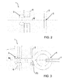
- FIG. 2 shows a schematic view of a mooring point 3 and a marker 5 for a door 1 according to an embodiment of the invention.
- FIG. 3 shows a schematic view of a mooring point 3 with mounted securing element 4 for a door 1 according to an embodiment of the invention.
- the securing element 4 is designed as an eyebolt, which is screwed into the nut 3.
- the marker 5 is unscrewed and therefore in FIG. 3 in parentheses.
- a cab includes two opposing doors 1.
- An eyebolt 4 is attached to the mooring 3 of a door 1 of the cab and another eye bolt 4 is attached to the mooring point 3 of the other door 1.
- the eyebolts 4 serve to be connected to each other by means of a connecting part 7 (eg a safety bar, safety rope, safety chain or safety belt, etc.), so that the two doors 1 from the inside against breaking open be secured. If an attempt is made to break up one of the doors 1, the connecting part 7 is subjected to tension and transmits the Aufbrechkraft to the opposite eyebolt 4, which receives the Aufbrechkraft and passes to the associated door 1 and thus prevents the breaking of quasi other door 1 or at least more difficult ,
- a connecting part 7 eg a safety bar, safety rope, safety chain or safety belt, etc.
- FIG. 4 shows a view from inside a door 1 according to another embodiment of the invention.
- a special feature of the door 1 of the FIG. 4 is that the securing element 4 is not an eyebolt, but a folding latch 4, which is foldable in a securing position to lock with a driver's cab fixed part.
- An advantage of this embodiment is that two doors 1 of a cab can be independently secured against breakage and one as in FIG. 3 shown connecting part 7 is not required.
Landscapes
- Engineering & Computer Science (AREA)
- Mechanical Engineering (AREA)
- Lock And Its Accessories (AREA)
- Body Structure For Vehicles (AREA)
Abstract
Description
- Die Erfindung betrifft eine Türe für ein Kraftfahrzeug, insbesondere ein Fahrerhaus eines Nutzfahrzeugs, vorzugsweise eines Lastkraftwagens.
- In manchen Regionen ist es ratsam, dass insbesondere Lastkraftwagen-Fahrer die Türen ihres Fahrerhauses für die Übernachtung oder Ruhepausen zusätzlich zum eigentlichen Türschloss von Innen verriegeln, weil die Türschlösser allein keinen ausreichenden Aufbrechschutz liefern. Aus der Praxis sind einige Türinnenverriegelungen zusätzlich zum eigentlichen Türschloss bekannt, die allerdings relativ komplex und in der Folge relativ teuer sind.
- Eine Aufgabe der Erfindung ist es, eine alternative Türsicherung für eine Fahrerhaustüre zusätzlich zu dem eigentlichen Türschloss zu schaffen, insbesondere eine preiswerte Türsicherung zusätzlich zu dem eigentlichen Türschloss.
- Diese Aufgabe kann mit den Merkmalen des unabhängigen Anspruchs gelöst werden. Vorteilhafte Weiterbildungen der Erfindung können den Unteransprüchen und der folgenden Beschreibung bevorzugter Ausführungsformen der Erfindung entnommen werden.
- Die Erfindung schafft eine Türe für ein Kraftfahrzeug, vorzugsweise ein Fahrerhaus eines Nutzfahrzeugs, insbesondere eines Lastkraftwagens. Die Türe umfasst ein Türschloss zum Verschließen der Türe und eine Tür-Innenseite, insbesondere eine Tür-Innenverkleidung. Die Türe zeichnet sich insbesondere dadurch aus, dass sie eine Festmachstelle für ein Sicherungselement zum Sichern der Türe zweckmäßig von Innen gegen unerlaubtes Aufbrechen zusätzlich zu dem Türschloss aufweist. Die Festmachstelle ist zweckmäßig hinter der Tür-Innenseite angeordnet ist, wobei die Tür-Innenseite eine Markierung zum Auffinden der Festmachstelle aufweist.
- Erst wenn ein Nutzer (Fahrer) weiß, dass er die Türe zusätzlich zum Türschloss gegen unerlaubtes Aufbrechen sichern möchte, bohrt er z. B. mit einer Handbohrmaschine ein Loch in die Tür-Innenseite, so dass ein Zugriff auf die Festmachstelle möglich wird. Daraufhin kann die Festmachstelle zweckmäßig durch Festmachen eines Sicherungselements genutzt werden, um die Türe von Innen gegen unerlaubtes Aufbrechen zu sichern.
- Wird keine zusätzliche Sicherung benötigt, ist letztgenanntes Vorgehen nicht erforderlich. Die Festmachstelle kann dann unsichtbar hinter der Tür-Innenseite verborgen bleiben.
- Die Festmachstelle ist zweckmäßig hinter der Markierung positioniert.
- Es ist möglich, dass die Mittelachse der Festmachstelle auf die Markierung trifft.
- Des Weiteren ist es möglich, dass die Mittelachse der Festmachstelle sich zumindest nahezu horizontal erstreckt, nämlich mit einer Abweichung von maximal +/-15°, +/- 10° oder +/- 5°. Alternativ oder ergänzend kann die Mittelachse der Festmachstelle zumindest nahezu rechtwinklig auf die Tür-Innenseite treffen, nämlich mit einer Abweichung von maximal +/-15°, +/-10° oder +/- 5°. Dadurch kann insbesondere gewährleistet werden, dass das Sicherungselement über das an der Markierung anzubringende Loch leicht die Festmachstelle findet.
- Es ist möglich, dass die Markierung mechanisch ausgeführt ist, z. B. als Vertiefung, und/oder farblich gekennzeichnet ist. Die mechanische Markierung kann z. B. als Körnerpunkt oder andere Vertiefung (z. B. kreuzförmige Ritze) ausgebildet sein, so dass die Markierung zweckmäßig zugleich das Herstellen des Lochs für den Zugriff auf die Festmachstelle erleichtert.
- Es ist möglich, dass die Festmachstelle ein Innengewinde umfasst, insbesondere eine Mutter mit Innengewinde. Die Mutter ist vorzugsweise eine Schweißmutter, die an die Tür-Tragstruktur geschweißt ist. Das Sicherungselement weist vorzugsweise ein Außengewinde auf.
- Das Sicherungselement kann z. B. ein Ring- oder Hakenteil sein, vorzugsweise mit Bund, das zweckmäßig an der Festmachstelle befestigbar ist. Das Ringteil kann z. B. als geschlitztes oder nicht-geschlitztes Ringteil ausgeführt sein.
- Das Ringsteil ist vorzugsweise eine Ringschraube.
- Das Hakenteil ist vorzugsweise eine Hakenschraube.
- Ebenso kann das Sicherungselement ein umklappbarer, z. B. dreh- oder schwenkbarer Riegel sein, der vorzugsweise an der Festmachstelle befestigbar ist und in eine Sicherungsstellung umlegbar ist, um vorzugsweise mit einem fahrerhausfesten Teil zu verriegeln.
- Die Türe umfasst vorzugsweise eine Tür-Tragstruktur, z. B. ein Tür-Gerippe. Die Festmachstelle ist vorzugsweise an der Tür-Tragstruktur ausgebildet, z. B. angeschweißt oder anderweitig befestigt. Die Tür-Tragstruktur ist vorzugsweise der Türrohbau.
- Die Tür-Tragstruktur umfasst insbesondere eine Säule, vorzugsweise eine Tür-B-Säule, an der die Festmachstelle ausgebildet ist.
- Zu erwähnen ist noch, dass die zusätzliche Türinnensicherung zweckmäßig nur von Innen betätigt werden kann.
- Zu erwähnen ist außerdem, dass die Tür-Innenseite meist als Türverkleidung bezeichnet wird.
- Die vorstehende Beschreibung bezieht sich auf eine Türe. Im Rahmen der Erfindung ist es allerdings möglich, dass ein Kraftfahrzeug, insbesondere ein Fahrerhaus zwei wie zuvor beschriebene, einander gegenüberliegende Türen umfasst.
- Die Aufbruchssicherung kann einerseits über die umklappbaren, insbesondere dreh- oder schwenkbaren, Riegel erfolgen.
- Die Aufbruchssicherung kann andererseits z. B. wie folgt erfolgen: Ein Sicherungselement (z. B. Ring- oder Hakenschraube) wird an der Festmachstelle der einen Türe befestigt und ein anderes Sicherungselement (z. B. Ring- oder Hakenschraube) wird an der Festmachstelle der anderen Türe befestigt. Die Sicherungselemente dienen dazu, um mittels eines Verbindungsteils (z. B. einem Sicherungsstab, Sicherungsseil, Sicherungskette oder Sicherungsgurt, etc.) miteinander verbunden zu werden, so dass die zwei Türen von Innen gegen Aufbrechen gesichert werden. Wird versucht, eine Türe aufzubrechen, wird das Verbindungsteil auf Zug beansprucht und überträgt die Aufbrechkraft auf das gegenüberliegende Sicherungselement, welches die Aufbrechkraft aufnimmt und somit ein Aufbrechen der Türe verhindert oder zumindest erschwert.
- Die Erfindung umfasst ferner ein Kraftfahrzeug und ein Fahrerhaus, vorzugsweise für einen Lastkraftwagen, mit zumindest einer Türe wie hierin offenbart. Das Kraftfahrzeug und das Fahrerhaus umfassen allerdings vorzugsweise zwei einander gegenüberliegende Türen wie hierin offenbart, so dass zwei Festmachstellen ebenfalls einander gegenüberliegend angeordnet sind und die daran befestigbaren Sicherungselemente über ein Verbindungsteil (z. B. einem Sicherungsstab, Sicherungsseil, Sicherungskette oder Sicherungsgurt, etc.) miteinander verbindbar sind, um die zwei Türen von innen gegen Aufbrechen zu sichern.
- Die zuvor beschriebenen bevorzugten Ausführungsformen und Merkmale der Erfindung sind miteinander kombinierbar. Andere vorteilhafte Weiterbildungen der Erfindung sind in den Unteransprüchen offenbart oder ergeben sich aus der folgenden Beschreibung bevorzugter Ausführungsformen der Erfindung in Verbindung mit den beigefügten Figuren.
- Figur 1a
- zeigt eine Ansicht von Innen einer Türe gemäß einer Ausführungsform der Erfindung,
- Figur 1b
- zeigt eine Schnittansicht entlang Linie A-A der
Figur 1 a, - Figur 2
- zeigt eine schematische Ansicht einer Festmachstelle und einer Markierung für eine Türe gemäß einer Ausführungsform der Erfindung,
- Figur 3
- zeigt eine schematische Ansicht einer Festmachstellte mit angebrachtem Sicherungselement für eine Türe gemäß einer Ausführungsform der Erfindung, und
- Figur 4
- zeigt eine Ansicht von Innen einer Türe gemäß einer Ausführungsform der Erfindung.
- Die unter Bezugnahme auf die Figuren beschriebenen Ausführungsformen stimmen teilweise überein, so dass ähnliche oder identische Teile mit dem gleichen Bezugszeichen versehen sind und zu deren Erläuterung auch auf die Beschreibung der anderen Ausführungsformen verwiesen wird, um Wiederholungen zu vermeiden.
-
Figur 1a zeigt eine Ansicht von Innen einer Türe 1 insbesondere für ein Fahrerhaus eines Nutzfahrzeugs, vorzugsweise eines Lastkraftwagens, gemäß einer Ausführungsform der Erfindung, währendFigur 1b eine zugehörige Schnittansicht entlang Linie A-A ausFigur 1 a zeigt. Die Türe 1 wird nachfolgend unter Bezugnahme auf dieFiguren 1 a und 1 b beschrieben. - Die Türe 1 kann zunächst wie in der Regel üblich ein Türschloss zum Verschließen der Türe 1, eine Tür-Tragstruktur 6, insbesondere Tür-Rohbau, und eine Tür-Innenseite 2, insbesondere eine Tür-Innenverkleidung zum Verkleiden der Tür-Tragstruktur 6, umfassen.
- Eine Besonderheit der Türe 1 ist, dass sie eine Festmachstelle 3 für ein Sicherungselement 4 (z. B.
Figuren 3 und4 ) zum Sichern der Türe 1 von Innen gegen unerlaubtes Aufbrechen aufweist und zwar zusätzlich zu dem eigentlichen Türschloss. Die Tür-Innenseite 2 umfasst zudem eine Markierung 5 zum Auffinden der Festmachstelle 3, hinter der die Festmachstelle 3 angeordnet ist. Die Festmachstelle 3 und die Markierung 5 sind so angeordnet, dass die Mittelachse M der Festmachstelle 3 auf die Markierung 5 trifft, sich zumindest nahezu horizontal erstreckt und zumindest nahezu rechtwinklig auf die Tür-Innenseite 2 trifft. Die Festmachstelle 3 bzw. die Markierung 5 sind in denFiguren 1 a und 1 b nur schematisch und insbesondere zu Darstellungszwecken vergrößert dargestellt. - Die Festmachstelle 3 umfasst eine Mutter mit Innengewinde, die an der Tür-B-Säule der Tür-Tragstruktur 6 ausgebildet ist.
- Die Markierung 5 ist als Körnerpunkt ausgeführt.
- Erst wenn der Fahrer die zusätzliche Türinnensicherung benötigt, bohrt er, z. B. mit einer Handbohrmaschine, ein Loch an der Markierung 5 in die Tür-Innenseite 2. Durch die Markierung 5 ist die Position über der Festmachstelle 3 exakt markiert und kann z. B. auf ca. 12mm aufgebohrt werden. Durch das Loch in der Tür-Innenseite 2 kann dann das Sicherungselement 4, z. B. eine Ring- oder Hakenschraube mit Bund oder ein drehbarer Riegel, an der Festmachstelle 3 befestigt werden. Die Türinnensicherung kann zweckmäßig nur von Innen betätigt werden.
-
Figur 2 zeigt eine schematische Ansicht einer Festmachstelle 3 und einer Markierung 5 für eine Türe 1 gemäß einer Ausführungsform der Erfindung. -
Figur 3 zeigt eine schematische Ansicht einer Festmachstelle 3 mit montiertem Sicherungselement 4 für eine Türe 1 gemäß einer Ausführungsform der Erfindung. Das Sicherungselement 4 ist als Ringschraube ausgeführt, die in die Mutter 3 geschraubt ist. Die Markierung 5 ist weggeschraubt und deshalb inFigur 3 in Klammern gesetzt. - Die Aufbruchssicherung wird wie folgt realisiert: Ein Fahrerhaus umfasst zwei einander gegenüberliegende Türen 1. Eine Ringschraube 4 wird an der Festmachstelle 3 der einen Türe 1 des Fahrerhauses befestigt und eine andere Ringschraube 4 wird an der Festmachstelle 3 der anderen Türe 1 befestigt. Die Ringschrauben 4 dienen dazu, um mittels eines Verbindungsteils 7 (z. B. ein Sicherungsstab, Sicherungsseil, Sicherungskette oder Sicherungsgurt, etc.) miteinander verbunden zu werden, so dass die zwei Türen 1 von Innen gegen Aufbrechen gesichert werden. Wird versucht, eine der Türen 1 aufzubrechen, wird das Verbindungsteil 7 auf Zug beansprucht und überträgt die Aufbrechkraft auf die gegenüberliegende Ringschraube 4, welches die Aufbrechkraft aufnimmt und an die zugehörige Türe 1 weitergibt und somit ein Aufbrechen der quasi anderen Türe 1 verhindert oder zumindest erschwert.
-
Figur 4 zeigt eine Ansicht von Innen einer Türe 1 gemäß einer anderen Ausführungsform der Erfindung. - Eine Besonderheit der Türe 1 der
Figur 4 ist, dass das Sicherungselement 4 keine Ringschraube ist, sondern ein umklappbarer Riegel 4, der in eine Sicherungsstellung klappbar ist, um mit einem fahrerhausfesten Teil zu verriegeln. Ein Vorteil dieser Ausführungsform ist, dass zwei Türen 1 eines Fahrerhauses unabhängig voneinander gegen Aufbrechen gesichert werden können und ein wie inFigur 3 gezeigtes Verbindungsteil 7 nicht erforderlich ist. - Die Erfindung ist nicht auf die oben beschriebenen bevorzugten Ausführungsformen beschränkt. Vielmehr ist eine Vielzahl von Varianten und Abwandlungen möglich, die ebenfalls von dem Erfindungsgedanken Gebrauch machen und deshalb in den Schutzbereich fallen. Darüber hinaus beansprucht die Erfindung auch Schutz für den Gegenstand und die Merkmale der Unteransprüche unabhängig von den in Bezug genommenen Merkmalen und Ansprüchen.
-
- 1
- Türe
- 2
- Tür-Innenseite, insbesondere Tür-Innenverkleidung
- 3
- Festmachstelle
- 4
- Sicherungselement
- 5
- Markierung
- 6
- Tür-Tragstruktur, insbesondere Türrohbau
- 7
- Verbindungselement
- M
- Mittelachse der Festmachstelle
Claims (14)
- Türe (1) für ein Kraftfahrzeug, insbesondere für ein Fahrerhaus eines Nutzfahrzeugs, mit: einem Türschloss zum Verschließen der Türe (1) und einer Tür-Innenseite (2), dadurch gekennzeichnet, dass die Türe (2) eine Festmachstelle (3) für ein Sicherungselement (4) zum Sichern der Türe (1) gegen unerlaubtes Aufbrechen zusätzlich zu dem Türschloss aufweist und die Festmachstelle (3) hinter der Tür-Innenseite (2) angeordnet ist, wobei die Tür-Innenseite (2) eine Markierung (5) zum Auffinden der Festmachstelle (3) aufweist.
- Türe (1) nach Anspruch 1, dadurch gekennzeichnet, dass die Festmachstelle (3) hinter der Markierung (5) angeordnet ist.
- Türe (1) nach Anspruch 1 oder 2, dadurch gekennzeichnet, dass die Mittelachse (M) der Festmachstelle (3) auf die Markierung (5) trifft.
- Türe (1) nach einem der vorhergehenden Ansprüche, dadurch gekennzeichnet, dass die Mittelachse (M) der Festmachstelle (3)- sich zumindest nahezu horizontal erstreckt und/oder- zumindest nahezu rechtwinklig auf die Tür-Innenseite (2) trifft.
- Türe (1) nach einem der vorhergehenden Ansprüche, dadurch gekennzeichnet, dass die Markierung (5) mechanisch ausgeführt ist und/oder farblich gekennzeichnet ist.
- Türe (1) nach einem der vorhergehenden Ansprüche, dadurch gekennzeichnet, dass die Markierung (5) einen Körnerpunkt oder eine andere Vertiefung umfasst.
- Türe (1) nach einem der vorhergehenden Ansprüche, dadurch gekennzeichnet, dass die Festmachstelle (3) ein Innengewinde umfasst oder eine Mutter ist und/oder das Sicherungselement (4) ein Außengewinde umfasst.
- Türe (1) nach einem der vorhergehenden Ansprüche, dadurch gekennzeichnet, dass das Sicherungselement (4) ein an der Festmachstelle (3) befestigbares Ring- oder Hakenteil ist, vorzugsweise mit Bund.
- Türe (1) nach einem der Ansprüche 1 bis 7, dadurch gekennzeichnet, dass das Sicherungselement (4) ein an der Festmachstelle (3) befestigbarer, umklappbarer Riegel ist, der in eine Sicherungsstellung umlegbar ist, um zweckmäßig mit einem fahrerhausfesten Teil zu verriegeln.
- Türe (1) nach einem der vorhergehenden Ansprüche, dadurch gekennzeichnet, dass die Türe (1) eine Tür-Tragstruktur (6) aufweist und die Festmachstelle (3) an der Tür-Tragstruktur (6) ausgebildet ist.
- Türe (1) nach einem der vorhergehenden Ansprüche, dadurch gekennzeichnet, dass die Türe (2) eine Tür-Tragstruktur (6) mit einer Säule, vorzugsweise einer Tür-B-Säule, aufweist und die Festmachstelle (3) an der Säule der Tür-Tragstruktur (6) ausgebildet ist.
- Kraftfahrzeug, mit zumindest einer Türe (1) nach einem der vorhergehenden Ansprüche.
- Fahrerhaus für ein Nutzfahrzeug, vorzugsweise einen Lastkraftwagen, mit zumindest einer Türe (1) nach einem der Ansprüche 1 bis 11.
- Kraftfahrzeug nach Anspruch 12 oder Fahrerhaus nach Anspruch 13, mit zwei Türen (1) nach einem der Ansprüche 1 bis 11, so dass zwei Festmachstellen (3) einander gegenüberliegend angeordnet sind und die daran befestigbaren Sicherungselemente (4) über ein Verbindungsteil (7) miteinander verbindbar sind, um die zwei Türen (1) von innen gegen Aufbrechen zu sichern.
Applications Claiming Priority (1)
| Application Number | Priority Date | Filing Date | Title |
|---|---|---|---|
| DE102014011102.4A DE102014011102A1 (de) | 2014-07-22 | 2014-07-22 | Türe für ein Kraftfahrzeug mit zusätzlicher Aufbruchsicherung |
Publications (2)
| Publication Number | Publication Date |
|---|---|
| EP2977245A1 true EP2977245A1 (de) | 2016-01-27 |
| EP2977245B1 EP2977245B1 (de) | 2019-08-28 |
Family
ID=53442431
Family Applications (1)
| Application Number | Title | Priority Date | Filing Date |
|---|---|---|---|
| EP15001659.0A Active EP2977245B1 (de) | 2014-07-22 | 2015-06-03 | Türe für ein kraftfahrzeug mit zusätzlicher aufbruchsicherung |
Country Status (4)
| Country | Link |
|---|---|
| EP (1) | EP2977245B1 (de) |
| CN (1) | CN105298231B (de) |
| DE (1) | DE102014011102A1 (de) |
| RU (1) | RU2699746C2 (de) |
Citations (5)
| Publication number | Priority date | Publication date | Assignee | Title |
|---|---|---|---|---|
| US3164409A (en) * | 1962-04-20 | 1965-01-05 | Richard K Rumble | Seat belt assembly |
| DE29607349U1 (de) * | 1996-04-23 | 1996-08-22 | Klabunde Frank | Vorrichtung zum Sichern von Türen |
| DE19821077A1 (de) * | 1998-05-12 | 1999-11-25 | Audi Ag | Fahrzeugtür |
| WO2001076900A1 (de) * | 2000-04-12 | 2001-10-18 | Acts Gmbh & Co. Kg | Kunststoffträgerteil angespritzt am fahrzeugtürinnenblech gegen feuchtigkeitseindringung und verfahren zu seiner herstellung |
| DE202010000432U1 (de) * | 2010-03-22 | 2010-06-24 | Fiamma S.P.A., Cardano Al Campo | Riegelverschlussvorrichtung |
Family Cites Families (4)
| Publication number | Priority date | Publication date | Assignee | Title |
|---|---|---|---|---|
| JP2003253942A (ja) * | 2002-02-28 | 2003-09-10 | Hideo Kataoka | 一般の鎖又は連結及び分離機能をもつ鎖を用いて、半開きの扉の内側に外から施錠、解錠のできる補助ロッカー装置 |
| BRPI1008925A2 (pt) * | 2009-02-18 | 2016-03-15 | Honda Motor Co Ltd | estrutura de montagem de partes de componentes |
| CN102343507A (zh) * | 2010-07-30 | 2012-02-08 | 信义汽车玻璃(深圳)有限公司 | 汽车玻璃附件安装定位方法 |
| CN202627739U (zh) * | 2012-04-27 | 2012-12-26 | 上海英伦帝华汽车部件有限公司 | 车门限位增强装置 |
-
2014
- 2014-07-22 DE DE102014011102.4A patent/DE102014011102A1/de not_active Withdrawn
-
2015
- 2015-06-03 EP EP15001659.0A patent/EP2977245B1/de active Active
- 2015-07-21 RU RU2015130229A patent/RU2699746C2/ru active
- 2015-07-22 CN CN201510432868.3A patent/CN105298231B/zh active Active
Patent Citations (5)
| Publication number | Priority date | Publication date | Assignee | Title |
|---|---|---|---|---|
| US3164409A (en) * | 1962-04-20 | 1965-01-05 | Richard K Rumble | Seat belt assembly |
| DE29607349U1 (de) * | 1996-04-23 | 1996-08-22 | Klabunde Frank | Vorrichtung zum Sichern von Türen |
| DE19821077A1 (de) * | 1998-05-12 | 1999-11-25 | Audi Ag | Fahrzeugtür |
| WO2001076900A1 (de) * | 2000-04-12 | 2001-10-18 | Acts Gmbh & Co. Kg | Kunststoffträgerteil angespritzt am fahrzeugtürinnenblech gegen feuchtigkeitseindringung und verfahren zu seiner herstellung |
| DE202010000432U1 (de) * | 2010-03-22 | 2010-06-24 | Fiamma S.P.A., Cardano Al Campo | Riegelverschlussvorrichtung |
Also Published As
| Publication number | Publication date |
|---|---|
| RU2699746C2 (ru) | 2019-09-09 |
| CN105298231A (zh) | 2016-02-03 |
| DE102014011102A1 (de) | 2016-01-28 |
| EP2977245B1 (de) | 2019-08-28 |
| RU2015130229A (ru) | 2017-01-26 |
| RU2015130229A3 (de) | 2018-12-06 |
| CN105298231B (zh) | 2020-04-17 |
Similar Documents
| Publication | Publication Date | Title |
|---|---|---|
| DE102005008092B4 (de) | Trägheitsaktivierter Mechanismus | |
| DE60018954T2 (de) | Türverriegelungssystem für einen container | |
| EP2699448B1 (de) | Verriegelungseinrichtung einer umklappbaren rückenlehne eines sitzes | |
| EP2977245B1 (de) | Türe für ein kraftfahrzeug mit zusätzlicher aufbruchsicherung | |
| DE102019123469A1 (de) | Tragbares Bügelschloss | |
| EP2366854B1 (de) | Schließsystem | |
| EP3699375A1 (de) | Hohles sicherungselement, schloss mit dem sicherungselement, verfahren zum herstellen eines sicherungselements, verfahren zum herstellen des schlosses und verfahren zum behindern eines diebstahlversuchs | |
| DE4104796C1 (de) | ||
| DE60225324T2 (de) | Behälterverriegelungsvorrichtung | |
| DE102014012590B4 (de) | Fahrzeugaufbau mit pendelbarer Bordwand | |
| DE1238782B (de) | Diebstahlsicherung fuer Kraftfahrzeuganhaenger | |
| DE202011003440U1 (de) | Rückhaltesystem für einen Fahrer eines Fahrzeugs | |
| DE19753024C2 (de) | Diebstahlsicheres Tretlagerschloß für Fahrräder | |
| DE3804872A1 (de) | Fahrradschloss zum blockieren der tretkurbeln | |
| DE102020103088B4 (de) | Drehstangenverschluss | |
| DE3537305A1 (de) | Anhaengevorrichtung, insbesondere fuer personenkraftwagen | |
| EP1762999B1 (de) | Befestigungsvorrichtung | |
| DE8009495U1 (de) | Sperrvorrichtung | |
| DE803818C (de) | Diebstahlsicherung fuer Kraftfahrzeuge | |
| DE2835603C2 (de) | ||
| DE801189C (de) | Diebstahlsicherung, insbesondere fuer Kraftfahrzeuge | |
| DE102022120206A1 (de) | Einbaugarnitur mit Betätigungssicherung und Betätigungssicherung | |
| DE2115598C3 (de) | Vorrichtung zum Absperren von Ab stellplatzen für Kraftfahrzeuge | |
| DE537275C (de) | Wagentuerfallenschloss mit Zylinderschloss, das einen den Druecker sperrenden Riegel aus dem Drueckerkoerper hervortreibt | |
| DE102008061394B3 (de) | Schließzylinder für Türen oder Klappen in Kraftfahrzeugen |
Legal Events
| Date | Code | Title | Description |
|---|---|---|---|
| PUAI | Public reference made under article 153(3) epc to a published international application that has entered the european phase |
Free format text: ORIGINAL CODE: 0009012 |
|
| AK | Designated contracting states |
Kind code of ref document: A1 Designated state(s): AL AT BE BG CH CY CZ DE DK EE ES FI FR GB GR HR HU IE IS IT LI LT LU LV MC MK MT NL NO PL PT RO RS SE SI SK SM TR |
|
| AX | Request for extension of the european patent |
Extension state: BA ME |
|
| 17P | Request for examination filed |
Effective date: 20160713 |
|
| GRAP | Despatch of communication of intention to grant a patent |
Free format text: ORIGINAL CODE: EPIDOSNIGR1 |
|
| STAA | Information on the status of an ep patent application or granted ep patent |
Free format text: STATUS: GRANT OF PATENT IS INTENDED |
|
| RIC1 | Information provided on ipc code assigned before grant |
Ipc: B60J 5/04 20060101AFI20190319BHEP Ipc: E05B 83/44 20140101ALI20190319BHEP |
|
| INTG | Intention to grant announced |
Effective date: 20190409 |
|
| GRAS | Grant fee paid |
Free format text: ORIGINAL CODE: EPIDOSNIGR3 |
|
| RAP1 | Party data changed (applicant data changed or rights of an application transferred) |
Owner name: MAN TRUCK & BUS SE |
|
| GRAA | (expected) grant |
Free format text: ORIGINAL CODE: 0009210 |
|
| STAA | Information on the status of an ep patent application or granted ep patent |
Free format text: STATUS: THE PATENT HAS BEEN GRANTED |
|
| AK | Designated contracting states |
Kind code of ref document: B1 Designated state(s): AL AT BE BG CH CY CZ DE DK EE ES FI FR GB GR HR HU IE IS IT LI LT LU LV MC MK MT NL NO PL PT RO RS SE SI SK SM TR |
|
| REG | Reference to a national code |
Ref country code: GB Ref legal event code: FG4D Free format text: NOT ENGLISH |
|
| REG | Reference to a national code |
Ref country code: CH Ref legal event code: EP |
|
| REG | Reference to a national code |
Ref country code: AT Ref legal event code: REF Ref document number: 1171981 Country of ref document: AT Kind code of ref document: T Effective date: 20190915 |
|
| REG | Reference to a national code |
Ref country code: IE Ref legal event code: FG4D Free format text: LANGUAGE OF EP DOCUMENT: GERMAN |
|
| REG | Reference to a national code |
Ref country code: DE Ref legal event code: R096 Ref document number: 502015010108 Country of ref document: DE |
|
| REG | Reference to a national code |
Ref country code: SE Ref legal event code: TRGR |
|
| REG | Reference to a national code |
Ref country code: NL Ref legal event code: FP |
|
| REG | Reference to a national code |
Ref country code: LT Ref legal event code: MG4D |
|
| PG25 | Lapsed in a contracting state [announced via postgrant information from national office to epo] |
Ref country code: FI Free format text: LAPSE BECAUSE OF FAILURE TO SUBMIT A TRANSLATION OF THE DESCRIPTION OR TO PAY THE FEE WITHIN THE PRESCRIBED TIME-LIMIT Effective date: 20190828 Ref country code: HR Free format text: LAPSE BECAUSE OF FAILURE TO SUBMIT A TRANSLATION OF THE DESCRIPTION OR TO PAY THE FEE WITHIN THE PRESCRIBED TIME-LIMIT Effective date: 20190828 Ref country code: BG Free format text: LAPSE BECAUSE OF FAILURE TO SUBMIT A TRANSLATION OF THE DESCRIPTION OR TO PAY THE FEE WITHIN THE PRESCRIBED TIME-LIMIT Effective date: 20191128 Ref country code: LT Free format text: LAPSE BECAUSE OF FAILURE TO SUBMIT A TRANSLATION OF THE DESCRIPTION OR TO PAY THE FEE WITHIN THE PRESCRIBED TIME-LIMIT Effective date: 20190828 Ref country code: PT Free format text: LAPSE BECAUSE OF FAILURE TO SUBMIT A TRANSLATION OF THE DESCRIPTION OR TO PAY THE FEE WITHIN THE PRESCRIBED TIME-LIMIT Effective date: 20191230 Ref country code: NO Free format text: LAPSE BECAUSE OF FAILURE TO SUBMIT A TRANSLATION OF THE DESCRIPTION OR TO PAY THE FEE WITHIN THE PRESCRIBED TIME-LIMIT Effective date: 20191128 |
|
| PG25 | Lapsed in a contracting state [announced via postgrant information from national office to epo] |
Ref country code: ES Free format text: LAPSE BECAUSE OF FAILURE TO SUBMIT A TRANSLATION OF THE DESCRIPTION OR TO PAY THE FEE WITHIN THE PRESCRIBED TIME-LIMIT Effective date: 20190828 Ref country code: LV Free format text: LAPSE BECAUSE OF FAILURE TO SUBMIT A TRANSLATION OF THE DESCRIPTION OR TO PAY THE FEE WITHIN THE PRESCRIBED TIME-LIMIT Effective date: 20190828 Ref country code: AL Free format text: LAPSE BECAUSE OF FAILURE TO SUBMIT A TRANSLATION OF THE DESCRIPTION OR TO PAY THE FEE WITHIN THE PRESCRIBED TIME-LIMIT Effective date: 20190828 Ref country code: RS Free format text: LAPSE BECAUSE OF FAILURE TO SUBMIT A TRANSLATION OF THE DESCRIPTION OR TO PAY THE FEE WITHIN THE PRESCRIBED TIME-LIMIT Effective date: 20190828 Ref country code: IS Free format text: LAPSE BECAUSE OF FAILURE TO SUBMIT A TRANSLATION OF THE DESCRIPTION OR TO PAY THE FEE WITHIN THE PRESCRIBED TIME-LIMIT Effective date: 20191228 Ref country code: GR Free format text: LAPSE BECAUSE OF FAILURE TO SUBMIT A TRANSLATION OF THE DESCRIPTION OR TO PAY THE FEE WITHIN THE PRESCRIBED TIME-LIMIT Effective date: 20191129 |
|
| PG25 | Lapsed in a contracting state [announced via postgrant information from national office to epo] |
Ref country code: TR Free format text: LAPSE BECAUSE OF FAILURE TO SUBMIT A TRANSLATION OF THE DESCRIPTION OR TO PAY THE FEE WITHIN THE PRESCRIBED TIME-LIMIT Effective date: 20190828 |
|
| PG25 | Lapsed in a contracting state [announced via postgrant information from national office to epo] |
Ref country code: EE Free format text: LAPSE BECAUSE OF FAILURE TO SUBMIT A TRANSLATION OF THE DESCRIPTION OR TO PAY THE FEE WITHIN THE PRESCRIBED TIME-LIMIT Effective date: 20190828 Ref country code: PL Free format text: LAPSE BECAUSE OF FAILURE TO SUBMIT A TRANSLATION OF THE DESCRIPTION OR TO PAY THE FEE WITHIN THE PRESCRIBED TIME-LIMIT Effective date: 20190828 Ref country code: RO Free format text: LAPSE BECAUSE OF FAILURE TO SUBMIT A TRANSLATION OF THE DESCRIPTION OR TO PAY THE FEE WITHIN THE PRESCRIBED TIME-LIMIT Effective date: 20190828 Ref country code: DK Free format text: LAPSE BECAUSE OF FAILURE TO SUBMIT A TRANSLATION OF THE DESCRIPTION OR TO PAY THE FEE WITHIN THE PRESCRIBED TIME-LIMIT Effective date: 20190828 |
|
| PG25 | Lapsed in a contracting state [announced via postgrant information from national office to epo] |
Ref country code: CZ Free format text: LAPSE BECAUSE OF FAILURE TO SUBMIT A TRANSLATION OF THE DESCRIPTION OR TO PAY THE FEE WITHIN THE PRESCRIBED TIME-LIMIT Effective date: 20190828 Ref country code: SK Free format text: LAPSE BECAUSE OF FAILURE TO SUBMIT A TRANSLATION OF THE DESCRIPTION OR TO PAY THE FEE WITHIN THE PRESCRIBED TIME-LIMIT Effective date: 20190828 Ref country code: SM Free format text: LAPSE BECAUSE OF FAILURE TO SUBMIT A TRANSLATION OF THE DESCRIPTION OR TO PAY THE FEE WITHIN THE PRESCRIBED TIME-LIMIT Effective date: 20190828 Ref country code: IS Free format text: LAPSE BECAUSE OF FAILURE TO SUBMIT A TRANSLATION OF THE DESCRIPTION OR TO PAY THE FEE WITHIN THE PRESCRIBED TIME-LIMIT Effective date: 20200224 |
|
| REG | Reference to a national code |
Ref country code: DE Ref legal event code: R097 Ref document number: 502015010108 Country of ref document: DE |
|
| PLBE | No opposition filed within time limit |
Free format text: ORIGINAL CODE: 0009261 |
|
| STAA | Information on the status of an ep patent application or granted ep patent |
Free format text: STATUS: NO OPPOSITION FILED WITHIN TIME LIMIT |
|
| PG2D | Information on lapse in contracting state deleted |
Ref country code: IS |
|
| 26N | No opposition filed |
Effective date: 20200603 |
|
| PG25 | Lapsed in a contracting state [announced via postgrant information from national office to epo] |
Ref country code: SI Free format text: LAPSE BECAUSE OF FAILURE TO SUBMIT A TRANSLATION OF THE DESCRIPTION OR TO PAY THE FEE WITHIN THE PRESCRIBED TIME-LIMIT Effective date: 20190828 |
|
| PG25 | Lapsed in a contracting state [announced via postgrant information from national office to epo] |
Ref country code: MC Free format text: LAPSE BECAUSE OF FAILURE TO SUBMIT A TRANSLATION OF THE DESCRIPTION OR TO PAY THE FEE WITHIN THE PRESCRIBED TIME-LIMIT Effective date: 20190828 |
|
| REG | Reference to a national code |
Ref country code: CH Ref legal event code: PL |
|
| GBPC | Gb: european patent ceased through non-payment of renewal fee |
Effective date: 20200603 |
|
| PG25 | Lapsed in a contracting state [announced via postgrant information from national office to epo] |
Ref country code: LU Free format text: LAPSE BECAUSE OF NON-PAYMENT OF DUE FEES Effective date: 20200603 |
|
| REG | Reference to a national code |
Ref country code: BE Ref legal event code: MM Effective date: 20200630 |
|
| PG25 | Lapsed in a contracting state [announced via postgrant information from national office to epo] |
Ref country code: CH Free format text: LAPSE BECAUSE OF NON-PAYMENT OF DUE FEES Effective date: 20200630 Ref country code: GB Free format text: LAPSE BECAUSE OF NON-PAYMENT OF DUE FEES Effective date: 20200603 Ref country code: IE Free format text: LAPSE BECAUSE OF NON-PAYMENT OF DUE FEES Effective date: 20200603 Ref country code: LI Free format text: LAPSE BECAUSE OF NON-PAYMENT OF DUE FEES Effective date: 20200630 |
|
| PG25 | Lapsed in a contracting state [announced via postgrant information from national office to epo] |
Ref country code: BE Free format text: LAPSE BECAUSE OF NON-PAYMENT OF DUE FEES Effective date: 20200630 |
|
| REG | Reference to a national code |
Ref country code: AT Ref legal event code: MM01 Ref document number: 1171981 Country of ref document: AT Kind code of ref document: T Effective date: 20200603 |
|
| PG25 | Lapsed in a contracting state [announced via postgrant information from national office to epo] |
Ref country code: AT Free format text: LAPSE BECAUSE OF NON-PAYMENT OF DUE FEES Effective date: 20200603 |
|
| PG25 | Lapsed in a contracting state [announced via postgrant information from national office to epo] |
Ref country code: MT Free format text: LAPSE BECAUSE OF FAILURE TO SUBMIT A TRANSLATION OF THE DESCRIPTION OR TO PAY THE FEE WITHIN THE PRESCRIBED TIME-LIMIT Effective date: 20190828 Ref country code: CY Free format text: LAPSE BECAUSE OF FAILURE TO SUBMIT A TRANSLATION OF THE DESCRIPTION OR TO PAY THE FEE WITHIN THE PRESCRIBED TIME-LIMIT Effective date: 20190828 |
|
| PG25 | Lapsed in a contracting state [announced via postgrant information from national office to epo] |
Ref country code: MK Free format text: LAPSE BECAUSE OF FAILURE TO SUBMIT A TRANSLATION OF THE DESCRIPTION OR TO PAY THE FEE WITHIN THE PRESCRIBED TIME-LIMIT Effective date: 20190828 |
|
| PGFP | Annual fee paid to national office [announced via postgrant information from national office to epo] |
Ref country code: DE Payment date: 20250626 Year of fee payment: 11 |
|
| PGFP | Annual fee paid to national office [announced via postgrant information from national office to epo] |
Ref country code: NL Payment date: 20250624 Year of fee payment: 11 |
|
| PGFP | Annual fee paid to national office [announced via postgrant information from national office to epo] |
Ref country code: FR Payment date: 20250624 Year of fee payment: 11 |
|
| PGFP | Annual fee paid to national office [announced via postgrant information from national office to epo] |
Ref country code: SE Payment date: 20250619 Year of fee payment: 11 |
|
| PGFP | Annual fee paid to national office [announced via postgrant information from national office to epo] |
Ref country code: IT Payment date: 20250623 Year of fee payment: 11 |