EP2964436B2 - Regulierbare anordnung zur umwandlung einer ebenen halterung, kassette, einheit und damit ausgestattete maschine - Google Patents
Regulierbare anordnung zur umwandlung einer ebenen halterung, kassette, einheit und damit ausgestattete maschine Download PDFInfo
- Publication number
- EP2964436B2 EP2964436B2 EP14728080.4A EP14728080A EP2964436B2 EP 2964436 B2 EP2964436 B2 EP 2964436B2 EP 14728080 A EP14728080 A EP 14728080A EP 2964436 B2 EP2964436 B2 EP 2964436B2
- Authority
- EP
- European Patent Office
- Prior art keywords
- tool
- bearing
- cassette
- spacer
- spacers
- Prior art date
- Legal status (The legal status is an assumption and is not a legal conclusion. Google has not performed a legal analysis and makes no representation as to the accuracy of the status listed.)
- Not-in-force
Links
- 230000001131 transforming effect Effects 0.000 title description 2
- 125000006850 spacer group Chemical group 0.000 claims description 42
- 238000005520 cutting process Methods 0.000 claims description 39
- 238000004049 embossing Methods 0.000 claims description 17
- 238000011144 upstream manufacturing Methods 0.000 claims description 15
- 238000004806 packaging method and process Methods 0.000 claims description 8
- 239000002184 metal Substances 0.000 claims description 2
- 239000002699 waste material Substances 0.000 claims description 2
- 239000000758 substrate Substances 0.000 claims 5
- 239000007787 solid Substances 0.000 claims 2
- 239000011295 pitch Substances 0.000 claims 1
- 230000009466 transformation Effects 0.000 description 38
- 238000004519 manufacturing process Methods 0.000 description 11
- 238000005096 rolling process Methods 0.000 description 7
- 239000000463 material Substances 0.000 description 5
- 230000009471 action Effects 0.000 description 4
- 230000000754 repressing effect Effects 0.000 description 4
- -1 polyethylene Polymers 0.000 description 3
- 239000004698 Polyethylene Substances 0.000 description 2
- 230000008859 change Effects 0.000 description 2
- 239000011159 matrix material Substances 0.000 description 2
- 238000000034 method Methods 0.000 description 2
- 229920000139 polyethylene terephthalate Polymers 0.000 description 2
- 239000005020 polyethylene terephthalate Substances 0.000 description 2
- 239000004743 Polypropylene Substances 0.000 description 1
- 230000006978 adaptation Effects 0.000 description 1
- 238000004026 adhesive bonding Methods 0.000 description 1
- 238000006243 chemical reaction Methods 0.000 description 1
- 230000000295 complement effect Effects 0.000 description 1
- 239000000428 dust Substances 0.000 description 1
- 239000000835 fiber Substances 0.000 description 1
- 229920002457 flexible plastic Polymers 0.000 description 1
- 238000003754 machining Methods 0.000 description 1
- 238000012423 maintenance Methods 0.000 description 1
- 238000012986 modification Methods 0.000 description 1
- 230000004048 modification Effects 0.000 description 1
- 239000000123 paper Substances 0.000 description 1
- 229920000573 polyethylene Polymers 0.000 description 1
- 229920001155 polypropylene Polymers 0.000 description 1
- 238000003825 pressing Methods 0.000 description 1
- 230000008569 process Effects 0.000 description 1
- 230000009467 reduction Effects 0.000 description 1
- 230000035945 sensitivity Effects 0.000 description 1
- 238000000926 separation method Methods 0.000 description 1
- 238000000844 transformation Methods 0.000 description 1
Images

Classifications
-
- B—PERFORMING OPERATIONS; TRANSPORTING
- B26—HAND CUTTING TOOLS; CUTTING; SEVERING
- B26D—CUTTING; DETAILS COMMON TO MACHINES FOR PERFORATING, PUNCHING, CUTTING-OUT, STAMPING-OUT OR SEVERING
- B26D7/00—Details of apparatus for cutting, cutting-out, stamping-out, punching, perforating, or severing by means other than cutting
- B26D7/26—Means for mounting or adjusting the cutting member; Means for adjusting the stroke of the cutting member
- B26D7/2628—Means for adjusting the position of the cutting member
- B26D7/265—Journals, bearings or supports for positioning rollers or cylinders relatively to each other
-
- B—PERFORMING OPERATIONS; TRANSPORTING
- B26—HAND CUTTING TOOLS; CUTTING; SEVERING
- B26D—CUTTING; DETAILS COMMON TO MACHINES FOR PERFORATING, PUNCHING, CUTTING-OUT, STAMPING-OUT OR SEVERING
- B26D7/00—Details of apparatus for cutting, cutting-out, stamping-out, punching, perforating, or severing by means other than cutting
- B26D7/18—Means for removing cut-out material or waste
- B26D7/1818—Means for removing cut-out material or waste by pushing out
-
- B—PERFORMING OPERATIONS; TRANSPORTING
- B26—HAND CUTTING TOOLS; CUTTING; SEVERING
- B26F—PERFORATING; PUNCHING; CUTTING-OUT; STAMPING-OUT; SEVERING BY MEANS OTHER THAN CUTTING
- B26F1/00—Perforating; Punching; Cutting-out; Stamping-out; Apparatus therefor
- B26F1/38—Cutting-out; Stamping-out
- B26F1/384—Cutting-out; Stamping-out using rotating drums
-
- B—PERFORMING OPERATIONS; TRANSPORTING
- B31—MAKING ARTICLES OF PAPER, CARDBOARD OR MATERIAL WORKED IN A MANNER ANALOGOUS TO PAPER; WORKING PAPER, CARDBOARD OR MATERIAL WORKED IN A MANNER ANALOGOUS TO PAPER
- B31B—MAKING CONTAINERS OF PAPER, CARDBOARD OR MATERIAL WORKED IN A MANNER ANALOGOUS TO PAPER
- B31B50/00—Making rigid or semi-rigid containers, e.g. boxes or cartons
- B31B50/14—Cutting, e.g. perforating, punching, slitting or trimming
- B31B50/16—Cutting webs
-
- B—PERFORMING OPERATIONS; TRANSPORTING
- B31—MAKING ARTICLES OF PAPER, CARDBOARD OR MATERIAL WORKED IN A MANNER ANALOGOUS TO PAPER; WORKING PAPER, CARDBOARD OR MATERIAL WORKED IN A MANNER ANALOGOUS TO PAPER
- B31F—MECHANICAL WORKING OR DEFORMATION OF PAPER, CARDBOARD OR MATERIAL WORKED IN A MANNER ANALOGOUS TO PAPER
- B31F1/00—Mechanical deformation without removing material, e.g. in combination with laminating
- B31F1/07—Embossing, i.e. producing impressions formed by locally deep-drawing, e.g. using rolls provided with complementary profiles
-
- B—PERFORMING OPERATIONS; TRANSPORTING
- B31—MAKING ARTICLES OF PAPER, CARDBOARD OR MATERIAL WORKED IN A MANNER ANALOGOUS TO PAPER; WORKING PAPER, CARDBOARD OR MATERIAL WORKED IN A MANNER ANALOGOUS TO PAPER
- B31F—MECHANICAL WORKING OR DEFORMATION OF PAPER, CARDBOARD OR MATERIAL WORKED IN A MANNER ANALOGOUS TO PAPER
- B31F1/00—Mechanical deformation without removing material, e.g. in combination with laminating
- B31F1/08—Creasing
- B31F1/10—Creasing by rotary tools
-
- B—PERFORMING OPERATIONS; TRANSPORTING
- B31—MAKING ARTICLES OF PAPER, CARDBOARD OR MATERIAL WORKED IN A MANNER ANALOGOUS TO PAPER; WORKING PAPER, CARDBOARD OR MATERIAL WORKED IN A MANNER ANALOGOUS TO PAPER
- B31B—MAKING CONTAINERS OF PAPER, CARDBOARD OR MATERIAL WORKED IN A MANNER ANALOGOUS TO PAPER
- B31B50/00—Making rigid or semi-rigid containers, e.g. boxes or cartons
- B31B50/005—Making rigid or semi-rigid containers, e.g. boxes or cartons involving a particular layout of the machinery or relative arrangement of its subunits
-
- B—PERFORMING OPERATIONS; TRANSPORTING
- B31—MAKING ARTICLES OF PAPER, CARDBOARD OR MATERIAL WORKED IN A MANNER ANALOGOUS TO PAPER; WORKING PAPER, CARDBOARD OR MATERIAL WORKED IN A MANNER ANALOGOUS TO PAPER
- B31B—MAKING CONTAINERS OF PAPER, CARDBOARD OR MATERIAL WORKED IN A MANNER ANALOGOUS TO PAPER
- B31B50/00—Making rigid or semi-rigid containers, e.g. boxes or cartons
- B31B50/25—Surface scoring
- B31B50/256—Surface scoring using tools mounted on a drum
-
- B—PERFORMING OPERATIONS; TRANSPORTING
- B31—MAKING ARTICLES OF PAPER, CARDBOARD OR MATERIAL WORKED IN A MANNER ANALOGOUS TO PAPER; WORKING PAPER, CARDBOARD OR MATERIAL WORKED IN A MANNER ANALOGOUS TO PAPER
- B31B—MAKING CONTAINERS OF PAPER, CARDBOARD OR MATERIAL WORKED IN A MANNER ANALOGOUS TO PAPER
- B31B50/00—Making rigid or semi-rigid containers, e.g. boxes or cartons
- B31B50/74—Auxiliary operations
- B31B50/88—Printing; Embossing
-
- B—PERFORMING OPERATIONS; TRANSPORTING
- B31—MAKING ARTICLES OF PAPER, CARDBOARD OR MATERIAL WORKED IN A MANNER ANALOGOUS TO PAPER; WORKING PAPER, CARDBOARD OR MATERIAL WORKED IN A MANNER ANALOGOUS TO PAPER
- B31F—MECHANICAL WORKING OR DEFORMATION OF PAPER, CARDBOARD OR MATERIAL WORKED IN A MANNER ANALOGOUS TO PAPER
- B31F2201/00—Mechanical deformation of paper or cardboard without removing material
- B31F2201/07—Embossing
- B31F2201/0707—Embossing by tools working continuously
- B31F2201/0715—The tools being rollers
- B31F2201/0753—Roller supporting, positioning, driving means
-
- B—PERFORMING OPERATIONS; TRANSPORTING
- B31—MAKING ARTICLES OF PAPER, CARDBOARD OR MATERIAL WORKED IN A MANNER ANALOGOUS TO PAPER; WORKING PAPER, CARDBOARD OR MATERIAL WORKED IN A MANNER ANALOGOUS TO PAPER
- B31F—MECHANICAL WORKING OR DEFORMATION OF PAPER, CARDBOARD OR MATERIAL WORKED IN A MANNER ANALOGOUS TO PAPER
- B31F2201/00—Mechanical deformation of paper or cardboard without removing material
- B31F2201/07—Embossing
- B31F2201/0784—Auxiliary operations
- B31F2201/0794—Cutting
Definitions
- the invention relates to a transformation cassette for a planar support, comprising an adjustable transformation arrangement for the planar support.
- a packaging production machine is intended for the manufacture of boxes, which form packaging, after folding and gluing.
- an initial planar support such as a continuous strip of cardboard, is unwound and printed by a printing unit, made up of printing units.
- the strip is then transferred to a processing unit, to make plate elements, in this case boxes.
- the transformation unit comprises at least one transformation arrangement provided with two rotary cylindrical tools, positioned parallel to one another, so as to cooperate with one another.
- the strip circulates between the two tools, to be transformed there.
- the two tools rotate in opposite directions to each other.
- the first tool is rotatably mounted in a first and a second bearing.
- the second tool is rotatably mounted in a third and a fourth bearing. Clamps are provided to securely hold the first and third bearings, as well as the second and fourth bearings.
- the transformation arrangement is most often provided so as to form a cassette.
- the cassette is inserted by sliding into each of the side frames of the unit.
- the cassette allows rapid change of tools, depending on the transformations of the support to be produced.
- the packaging manufacturer has at least two cassettes. A first cassette is in the machine during production and is adapted according to the transformation work in progress. During this time, a second cassette is being assembled and adjusted to be adapted according to the following transformation work. When changing jobs, the operator takes out the old cassette and inserts the new cassette, minimizing machine downtime.
- one of the arrangements or one of the cassettes is respectively a rotary cutting arrangement or a rotary cutting cassette.
- a first cylindrical cutting tool is provided with knives, and a second cylindrical tool is smooth, and is called an anvil.
- the knife edges of the cutting tool must pass as close as possible to the anvil cylinder, in order to make a clean cut.
- the edges of these knives must not, however, touch the anvil cylinder, as they will be irreparably destroyed during rotation.
- the material of the support i.e. the fibers in the case of cardboard, must not appear at the cutout. It is also not desirable to have dust from the cutting of the material constituting the support.
- each end of the two rotary cylindrical tools comprises a rolling crown.
- the rolling crown of one of the tools rolls on the rolling crown of the other of the tools (see document EP-0'764'505 ).
- one of the arrangements or one of the cassettes is respectively a rotary delivery arrangement or a rotary delivery cassette.
- a first cylindrical tool for repressing is provided with a male form or repressing matrix
- a second cylindrical tool is provided with a form or complementary female repressing matrix.
- the discharge must be clean, without breaking the edges or the bottom of the discharge.
- the optimal radial interval between the two rotary cylindrical tools is set in the hundredth.
- the first and second bearings are respectively pressurized using jacks against the third and fourth bearings, in order to apply the desired cutting pressure while obtaining the radial interval between the two tools.
- a main object of the present invention is to develop a processing arrangement for a planar support for a processing unit in a packaging production machine.
- a second objective is to provide a transformation arrangement with rotary tools allowing a simpler, more sensitive and therefore extremely precise adjustment of the interval between the two tools to be obtained.
- a third objective is to provide an arrangement making it possible to improve the reproducibility of the adjustments between the rotary tools.
- a fourth objective is to solve the technical problems mentioned for the arrangements of the state of the art.
- a fifth objective is to simplify and facilitate any change of tools in an arrangement, while simplifying and optimizing the subsequent adjustments.
- a sixth objective consists in providing a cassette comprising a transformation arrangement for the transformation unit. Yet another objective is that of successfully inserting a processing unit into a packaging production machine.
- a transformation arrangement for a planar support includes a first rotary cylindrical transformation tool and a second rotary cylindrical transformation tool.
- the first rotary cylindrical transformation tool and the second rotary rotary transformation tool are arranged between them and cooperate with each other, to ensure a transformation of the planar support.
- the transformation arrangement for the planar support comprises a first lateral bearing and a second lateral bearing.
- the first lateral bearing and the second lateral bearing hold the first rotary cylindrical transformation tool for rotation.
- the transformation arrangement for the planar support includes a third lateral bearing and a fourth lateral bearing.
- the third lateral bearing and the fourth lateral bearing hold the second rotary cylindrical transformation tool for rotation.
- the transformation arrangement for the flat support comprises adjustment means in the form of spacers with an inclined face and sliding therebetween.
- the spacers are used to adjust the gap between the first bearing and the third bearing.
- the spacers are used to adjust the gap between the second level and the fourth level.
- the spacers make it possible to adjust a radial interval between the first rotary cylindrical transformation tool and the second rotary cylindrical transformation tool.
- the transformation arrangement for the planar support is characterized in that the adjustment means comprise two spacers which are interposed between the first lateral bearing and the third lateral bearing, and two spacers which are interposed between the second lateral bearing and the fourth lateral bearing.
- the adjustment precision is much higher.
- the adjustment makes it possible to balance and adjust the level of each of the two bearings on one side and the other of the arrangement. Such adjustments make it possible to maintain an optimal transformation of the planar support throughout the production. Four adjustment possibilities are possible with four spacers. This multiplication of settings also simplifies the manufacture of bearings.
- the transformation arrangement for the planar support is characterized in that the spacer is moved by a differential screw having a first external thread, cooperating with a first internal thread of an integral part of one of the lateral bearings, as well as a second external thread, different from the first external thread and cooperating with a second internal thread of the spacer.
- the adjustment can be carried out with much more precision, depending on the characteristics of the dimensions of the threads chosen.
- Such an adjustment makes it possible to obtain and maintain a high-quality transformation of the planar support throughout the production.
- a fine adjustment makes it possible to gradually compensate for the wear of one or more rotary cylindrical transformation tools which occur as and when they are used.
- the service life of the tool (s) is increased.
- An optimized setting also makes it possible to have bearings that are simpler to manufacture, requiring less machining precision.
- the fine and precise adjustment makes it possible to reduce the time for adjusting the radial interval between the two tools.
- the flat support is defined, by way of non-exhaustive example, as being of a continuous strip material, such as paper, flat cardboard, corrugated cardboard, laminated corrugated cardboard, flexible plastic, for example polyethylene ( PE), polyethylene terephthalate (PET), bioriented polypropylene (BOPP), or other materials.
- PE polyethylene
- PET polyethylene terephthalate
- BOPP bioriented polypropylene
- a transformation unit for a flat support is characterized in that it is equipped with at least one transformation cassette for the planar support, this cassette being provided with a transformation arrangement for the flat support, having one or more of the technical characteristics described below and claimed.
- a transformation unit for a planar support is characterized in that it comprises at least one transformation arrangement for the planar support, having one or more of the technical characteristics described below and claimed. .
- a machine for producing packaging from a flat support comprises at least one processing unit for the flat support, having one or more of the characteristics techniques described below and claimed.
- a packaging production machine processes a flat material or support, which in this case is a continuous strip support, for example flat cardboard.
- the machine comprises a unit for transforming a support 1 to transform the strip 2.
- the direction of advance or of travel (arrow F in Figure 1 ) of the strip 2 and the strip transformed in the longitudinal direction indicates the upstream direction and the downstream direction in the unit 1.
- the front and rear positions are defined with respect to the transverse direction, as being respectively the driver or operator side and the opposite driver or operator side.
- the machine may have a tape unwinder, units such as printing units, means for controlling the quality and register of printing, a tape guide, and others, which are positioned upstream of the machine. unit 1.
- the processing unit 1 is an embossing, upsetting and cutting unit.
- the strip 2 arrives in the unit 1 with a constant speed by its transverse side upstream.
- An introduction group comprising drive rollers and deflection rollers for the strip 2 is provided at the input of the unit 1.
- the unit 1 transforms the strip 2, successively by embossing it, pushing it back and cutting out.
- Unit 1 delivers poses or transformed boxes 3, being consequently in embossed flat cardboard, turned up and cut out.
- the boxes 3 exit from the unit 1 with the same constant speed by its transverse side downstream.
- the boxes 3 made up in unit 1 are then separated laterally and longitudinally from one another in a separation station and then received in a reception station (not shown).
- the unit 1 firstly comprises a first arrangement ensuring the embossing 4, arranged upstream, ie at the inlet of this unit 1.
- the embossing arrangement 4 is equipped with an upper rotary embossing tool 6, positioned parallel to a lower rotary embossing tool 7.
- an embossing cassette 8 comprises the embossing arrangement 4.
- the unit 1 comprises a second delivery arrangement 9, arranged downstream of the embossing arrangement 4.
- the delivery arrangement 9 is equipped with an upper rotary delivery tool 11, positioned parallel to a lower rotary tool of delivery 12.
- a delivery cassette 13 comprises the delivery arrangement 9.
- Unit 1 comprises a third arrangement ensuring cutting 14, arranged downstream of the delivery arrangement 9, ie at the output of this unit 1.
- the cutting arrangement 14 is equipped with an upper rotary cutting tool 16, positioned parallel to a lower rotary cutting tool 17.
- a cutting cassette 18 comprises the cutting arrangement 14.
- the arrangements 4, 9 and 14, and thus the cassettes 8, 13 and 18, are placed one after the other so that each one carries out their respective transformation, by embossing, upsetting, and cutting of the strip 2.
- a tool for ejection of waste in the form of a cylinder fitted with ejection needles can also be provided in place of the lower rotary cutting tool 17.
- Other combinations are possible, such as an upper cylinder forming both a cutting tool and a press tool.
- each of the embossing tools 6 and 7, of upsetting 11 and 12, and of cutting 16 and 17 is oriented transversely relative to the direction of travel F of the strip 2.
- the direction of rotation (arrow Rs in Figure 2 ) upper embossing tools 6, repressing tools 11, and cutting tools 16 are reversed with respect to the direction of rotation (arrow Ri in Figure 2 ) lower embossing tools 7, upsetting tools 12, and cutting tools 17.
- the embossing 8, upsetting 13 and cutting 18 cassettes are capable of being introduced into a frame 19 of the unit 1, to be fixed to the frame 19, put into production, then conversely, able to be separated from the frame 19, and to be extracted from this frame 19.
- the unit 1 thus comprises three transverse housings provided in the frame 19 for each of the three cassettes 8, 13 and 18.
- the cassettes 8, 13 and 18 are introduced vertically, by the high relative to the frame 19 in the transverse housings. Conversely, the cassettes 8, 13 and 18 can be extracted vertically relative to the frame 19, out of their respective transverse housing.
- the cutting arrangement 14, and therefore the cutting cassette 18, includes (see Figure 2 ) the rotary cylindrical upper tool 16 provided with cutting threads (not shown) machined or attached on its circumference depending on the configuration of the boxes to be produced.
- the rotary cylindrical lower tool or anvil 17 has a smooth circumference.
- the strip 2 travels F in the radial interval 20 between the upper tool 16 and the anvil 17.
- the upper tool 16 is arranged so as to cooperate with the anvil 17 to transform, ie cut the strip 2.
- the upper tool 16 is provided at each of its ends with a rolling crown 21, respectively 22.
- the anvil 17 is provided at each of its ends with a rolling crown 23, respectively 24.
- the rolling crowns 21 and 22 of the upper tool 16 come into contact, bear on, and roll on the opposite rolling rings 23 and 24 of the anvil 17.
- the cutting arrangement 14, and therefore the cutting cassette 18, comprises a first upper front bearing 26 and a second upper rear bearing 27 now for rotation the first tool, ie the upper tool 16 by its axis of rotation 28
- the cutting arrangement 14, and therefore the cutting cassette 18, comprises a third lower front bearing 29 and a fourth lower rear bearing 31 now for rotation of the second tool, ie the anvil 17 by its axis of rotation 32
- the base of the two lower bearings 29 and 31 rests on the frame 19 when the cutting cassette 18 is inserted in the unit 1.
- the cutting arrangement 14, and therefore the cutting cassette 18, comprises drive means intended to rotate the two tools 16 and 17. These means are formed with a first upper pinion 33 for the upper tool 16 fixed at the rear on its axis of rotation 28. This first pinion 33 meshes with a second lower pinion 34 for the anvil 17 fixed at the rear on its axis of rotation 32. When the cassette 18 is inserted in the frame 19, the teeth of the first pinion 33 mesh with the teeth of a pinion conjugate of an electric motor for driving in rotation.
- the first upper front bearing 26 of the upper tool 16 is fixed to the third lower front bearing 29 of the anvil 17, and the second upper rear bearing 27 of the upper tool 16 is fixed to the fourth lower rear bearing 31 of the anvil 17, so as to constitute the cutting cassette 18.
- elements, in the form of four tie rods 36, front upstream, front downstream, rear upstream, and rear downstream pass vertically respectively the upper front bearing 26 and the upper rear bearing 27, on either side of the axis of rotation 28 of the upper tool 16.
- the lower end of each of the four front and rear tie rods 36 is threaded and screws in a thread respectively in the lower front bearing 29 and in the lower rear bearing 31.
- the cutting cassette 18, as well as the embossing 8 and delivery 13 cassettes, comprise two gripping lugs 41 each provided at the upper face of the upper front bearing 26 and the upper rear bearing 27.
- the two lugs 41 are intended to cooperate with lifting means for lifting and transporting the cassette 8, 13 and 18.
- adjustment means 42 are interposed between the first upper front bearing 26 and the third lower front bearing 29, and between the second upper rear bearing 27 and the fourth lower rear bearing 31.
- the adjustment means 42 comprise spacers, in this case similar to corners, which are movable by sliding. According to the invention, four spacers 43, 44, 46 and 47 are provided.
- a front upstream spacer 43, a front downstream spacer 44, a rear upstream spacer 46 (visible by transparency in Figure 2 ) and a rear downstream spacer 47 allow four different adjustments, front and rear, upstream and downstream.
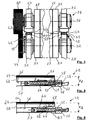
- a gap e (see Figure 4 ) varies, upstream and downstream, between the first bearing 26 and the third front bearing 29 and between the second bearing 27 and the fourth rear bearing 31.
- the difference e is obtained due to an upper inclined face 48 of l 'spacer 43. Adjustments of the horizontality in the longitudinal direction and in the transverse direction are possible with the four spacers 43, 44, 46 and 47.
- the spacer 43 is in the form of a metal wedge with two branches 49 and 51, leaving a space to be able to pass the corresponding tie rod 36.
- the two branches 49 and 51 of the spacer 43 are pressed against the face upper of the lower front bearing 29.
- the two branches 49 and 51 have the upper inclined face 48.
- An intermediate piece 52 is favorably secured to the underside of the first upper bearing 26 or to the second upper bearing 27.
- the two arms 53 and 54 of the insert 52 comprise an opposite inclined lower face 56 , corresponding to the upper inclined face 48 of the spacer 43.
- the action to adjust the gap e is defined as the action to close the gap e between the bearings 26, 27, 29 and 31, in the case of the cutting tools 16 and 17, the adjustment of the interval precise 20 being obtained by crowns 21, 22, 23 and 24.
- the action to adjust the gap e is defined as the action to adjust the gap e of the precise interval 20 in the case of the embossing tools 6 and 7 and delivery 11 and 12.
- the spacer 43 is at the bottom relative to the intermediate piece 52, and consequently the difference e1 is the smallest.
- the spacer 43 is advanced relative to the intermediate piece 52, and consequently the difference e2 is greater, greater than the smallest difference e1.
- the spacer 43 is moved by sliding S thanks to a screw 57.
- the screw 57 is advantageously a differential screw which has a first external thread 58 cooperating with a first internal thread 59 of a part 61 integral with the bearing lower 29.
- the screw 57 mechanically connects the sliding spacer 43 to the stationary part 61.
- the screw 57 has a second external thread 62 cooperating with a second internal thread 63 formed in the mobile spacer 43.
- the two threads 58 and 62, and their corresponding thread 59 and 63 allow fine adjustment of the gap e, in depending on the step difference chosen.
- the pitch difference corresponds to the sensitivity desired for the adjustment.
- the screw 57 has a different diameter at the two threads 58 and 62.
- the second thread 62 has a diameter greater than the first thread 58.
- the spacers 43, 44, 46 and 47, and the insert 52 have an elongated shape.
- the inclined face 48 of all the spacers 43, 44, 46 and 47, and consequently the inclined face 56 of the intermediate piece 52, is preferably oriented in the longitudinal direction. In other words, the great length of the spacers 43, 44, 46 and 47 and of the intermediate piece 52 is parallel to the longitudinal direction. Access to the screws 57 is done upstream and downstream of the arrangement 14 and / or of the cassette 18, which is more ergonomic for the operator.
- the cutting arrangement 14 also advantageously comprises a flat shim of predefined thickness 64, interposed between the first upper bearing 26 or the second upper bearing 27 and the intermediate piece 52 with inclined face 56.
- the flat shim 64 allows adaptation when using cylinders 16 and 17 of different diameters.
Claims (9)
- Kassette zur Verarbeitung für einen ebenen Träger (2), die eine Anordnung zur Verarbeitung (4, 9, 14) für einen ebenen Träger (2) umfasst, umfassend:- ein erstes und ein zweites rotierendes zylindrisches Werkzeug zur Verarbeitung (16, 17), die angeordnet sind und miteinander zusammenwirken, um den Träger (2) zu verarbeiten,- ein erstes und ein zweites Seitenlager (26, 27), die das erste Werkzeug (16) für eine Drehung (Rs) halten,- ein drittes und ein viertes Seitenlager (29, 31), die das zweite Werkzeug (17) für eine Drehung (Ri) halten,
wobei das erste Seitenlager (26) des ersten Werkzeugs (16) am dritten Seitenlager (29) des zweiten Werkzeugs (17) befestigt ist und wobei das zweite Seitenlager (27) des ersten Werkzeugs (16) am vierten Seitenlager (31) des zweiten Werkzeugs (17) befestigt ist, um die Kassette (18) zu bilden,- vier Zugelemente (36), vorne vorgelagert, vorne nachgelagert, hinten vorgelagert und hinten nachgelagert, die jeweils vertikal das erste Seitenlager (26) und das zweite Seitlanger (27) beiderseits der Drehachse (28) des ersten Werkzeugs (16) durchqueren, um die Kassette (18) in einem Stück zu halten, und- Mittel zum Einstellen (42), um den jeweiligen Abstand (e, e1, e2) zwischen dem ersten und dem dritten Lager (26, 29) und zwischen dem zweiten und dem vierten Lager (27, 31) anzupassen, um einen radialen Abstand (20) zwischen den zwei Werkzeugen (16, 17) einzustellen,dadurch gekennzeichnet,
dass die Mittel zum Einstellen (42) in Form von mit einer geneigten Fläche (48) versehenen und gleitbaren (S) Abstandshaltern (43, 44, 46, 47) sind und zwei Abstandshalter (43, 44), die zwischen dem ersten und dem dritten Lager (26, 29) eingefügt sind, und zwei Abstandshalter (46, 47) umfassen, die zwischen dem zweiten und dem vierten Lager (27, 31) eingefügt sind, und
dass die Abstandshalter (43, 44, 46, 47) sich unter der Form eines metallischen Keils mit zwei Zweigen (49, 51) darstellen, der einen Raum lässt, um das entsprechende Zugelement (36) durchführen zu können. - Kassette nach Anspruch 1, dadurch gekennzeichnet, dass der Abstandshalter (43) durch eine Differentialschraube (57) bewegt (S) wird, die ein erstes Gewinde (58), das mit einem Innengewinde (59) eines Teils (61) zusammenwirkt, das mit einem der Lager (29) fest verbunden ist, und ein zweites Gewinde (62) besitzt, das von dem ersten Gewinde (58) verschieden ist und mit einem Innengewinde (63) des Abstandshalters (43) zusammenwirkt.
- Kassette nach Anspruch 2, dadurch gekennzeichnet, dass die Gewinde (58, 62) der Schraube (57) unterschiedliche Teilungen haben.
- Kassette nach einem der vorhergehenden Ansprüche, dadurch gekennzeichnet, dass die geneigte Fläche (48) des Abstandshalters (43) in der Längsrichtung ausgerichtet ist.
- Kassette nach einem der vorhergehenden Ansprüche, dadurch gekennzeichnet, dass der Abstandshalter (43, 44, 46, 47) jeweils zwischen dem dritten oder dem vierten Lager (29, 31) und einem Teil (52) mit geneigter Fläche (56) gleitet (S), das mit dem ersten oder zweiten Lager (26, 27) fest verbunden ist.
- Kassette nach Anspruch 5, dadurch gekennzeichnet, dass sie ferner einen flachen Keil mit vorbestimmte Dicke (64) umfasst, der zwischen dem ersten oder zweiten Lager (26, 27) und dem Teil (52) mit geneigter Fläche (56) eingefügt ist.
- Kassette nach einem der vorhergehenden Ansprüche, dadurch gekennzeichnet, dass das erste und das zweite Werkzeug ein Werkzeug zum Schneiden (16, 17) und/oder ein Werkzeug zum Prägen (6, 7) und/oder ein Werkzeug zum Stauchen (11, 12) und/oder ein Werkzeug zum Auswerfen von Abfällen sind.
- Einheit zur Verarbeitung für einen ebenen Träger (2), dadurch gekennzeichnet, dass sie mit mindestens einer Kassette zur Verarbeitung (8, 13, 18) nach einem der vorhergehenden Ansprüche ausgestattet ist.
- Maschine zur Herstellung von einer Verpackung ausgehend von einem flachen Träger (2), dadurch gekennzeichnet, dass sie eine Einheit zur Verarbeitung (1) nach Anspruch 8 umfasst.
Priority Applications (2)
| Application Number | Priority Date | Filing Date | Title |
|---|---|---|---|
| EP14728080.4A EP2964436B2 (de) | 2013-03-07 | 2014-03-04 | Regulierbare anordnung zur umwandlung einer ebenen halterung, kassette, einheit und damit ausgestattete maschine |
| EP17020021.6A EP3181312B1 (de) | 2013-03-07 | 2014-03-04 | Regulierbare anordnung zur umwandlung einer ebenen halterung, kassette, einheit und damit ausgerüstete maschine |
Applications Claiming Priority (3)
| Application Number | Priority Date | Filing Date | Title |
|---|---|---|---|
| EP13001150 | 2013-03-07 | ||
| PCT/EP2014/000544 WO2014135265A1 (fr) | 2013-03-07 | 2014-03-04 | Agencement reglable de transformation d'un support plan, cassette, unite et machine ainsi equipee |
| EP14728080.4A EP2964436B2 (de) | 2013-03-07 | 2014-03-04 | Regulierbare anordnung zur umwandlung einer ebenen halterung, kassette, einheit und damit ausgestattete maschine |
Related Child Applications (2)
| Application Number | Title | Priority Date | Filing Date |
|---|---|---|---|
| EP17020021.6A Division-Into EP3181312B1 (de) | 2013-03-07 | 2014-03-04 | Regulierbare anordnung zur umwandlung einer ebenen halterung, kassette, einheit und damit ausgerüstete maschine |
| EP17020021.6A Division EP3181312B1 (de) | 2013-03-07 | 2014-03-04 | Regulierbare anordnung zur umwandlung einer ebenen halterung, kassette, einheit und damit ausgerüstete maschine |
Publications (3)
| Publication Number | Publication Date |
|---|---|
| EP2964436A1 EP2964436A1 (de) | 2016-01-13 |
| EP2964436B1 EP2964436B1 (de) | 2017-06-07 |
| EP2964436B2 true EP2964436B2 (de) | 2020-04-15 |
Family
ID=47901729
Family Applications (2)
| Application Number | Title | Priority Date | Filing Date |
|---|---|---|---|
| EP17020021.6A Not-in-force EP3181312B1 (de) | 2013-03-07 | 2014-03-04 | Regulierbare anordnung zur umwandlung einer ebenen halterung, kassette, einheit und damit ausgerüstete maschine |
| EP14728080.4A Not-in-force EP2964436B2 (de) | 2013-03-07 | 2014-03-04 | Regulierbare anordnung zur umwandlung einer ebenen halterung, kassette, einheit und damit ausgestattete maschine |
Family Applications Before (1)
| Application Number | Title | Priority Date | Filing Date |
|---|---|---|---|
| EP17020021.6A Not-in-force EP3181312B1 (de) | 2013-03-07 | 2014-03-04 | Regulierbare anordnung zur umwandlung einer ebenen halterung, kassette, einheit und damit ausgerüstete maschine |
Country Status (8)
| Country | Link |
|---|---|
| US (1) | US10391662B2 (de) |
| EP (2) | EP3181312B1 (de) |
| JP (1) | JP6195632B2 (de) |
| KR (1) | KR101809806B1 (de) |
| CN (1) | CN105189061B (de) |
| ES (2) | ES2673501T3 (de) |
| TW (1) | TWI551432B (de) |
| WO (1) | WO2014135265A1 (de) |
Families Citing this family (25)
| Publication number | Priority date | Publication date | Assignee | Title |
|---|---|---|---|---|
| JP6198313B2 (ja) | 2013-10-01 | 2017-09-20 | ホリゾン・インターナショナル株式会社 | 回転式打抜機 |
| JP2017526542A (ja) * | 2014-08-26 | 2017-09-14 | ハイコン システムズ リミテッドHighcon Systems Ltd | 基材ストリッピングの方法及び装置 |
| US10618240B2 (en) | 2014-11-05 | 2020-04-14 | Bobst Mex Sa | Method for production of a female embossing tool, a female embossing tool, and an embossing module equipped therewith |
| KR20170086086A (ko) | 2014-12-04 | 2017-07-25 | 봅스트 맥스 에스에이 | 공구-홀더 칼럼, 편평한 기판을 변환하기 위한 유닛, 및 변환 유닛에 관련한 회전 공구의 제거 및 탑재 방법 |
| KR102539810B1 (ko) * | 2014-12-04 | 2023-06-02 | 봅스트 맥스 에스에이 | 편평한 지지부의 변환을 위한 방법 및 작업 스테이션 |
| MX2018012431A (es) * | 2016-04-12 | 2019-01-31 | Ykk Corp | Dispositivo automatico de corte de tamaño. |
| DE202016102593U1 (de) * | 2016-05-13 | 2016-06-10 | Bobst Mex Sa | Vorrichtung zum Bearbeiten von Werkstückbögen |
| CN106272695B (zh) * | 2016-08-26 | 2018-04-10 | 松嘉(泉州)机械有限公司 | 一种纸尿裤耳片短切装置 |
| GB201703644D0 (en) * | 2017-03-07 | 2017-04-19 | Elopak As | Improvements in or relating to toller mounting arrangements |
| EP3648964A1 (de) * | 2017-07-06 | 2020-05-13 | Bobst Mex Sa | Rillmaschine, rillzylinder für die rillmaschine und verfahren zum rillen von blättern |
| DE202017104039U1 (de) * | 2017-07-06 | 2017-09-22 | Bobst Mex Sa | Falzplatte zum Falzen eines Bogens aus Papier, Pappe, Karton, Folie oder einem ähnlichen Material |
| EP3648908A1 (de) * | 2017-07-06 | 2020-05-13 | Bobst Mex Sa | Verfahren zur herstellung zum falten von blättern |
| US10642551B2 (en) | 2017-07-14 | 2020-05-05 | Georgia-Pacific Corrugated Llc | Engine for generating control plans for digital pre-print paper, sheet, and box manufacturing systems |
| US20190016551A1 (en) | 2017-07-14 | 2019-01-17 | Georgia-Pacific Corrugated, LLC | Reel editor for pre-print paper, sheet, and box manufacturing systems |
| US11520544B2 (en) | 2017-07-14 | 2022-12-06 | Georgia-Pacific Corrugated Llc | Waste determination for generating control plans for digital pre-print paper, sheet, and box manufacturing systems |
| US11485101B2 (en) | 2017-07-14 | 2022-11-01 | Georgia-Pacific Corrugated Llc | Controls for paper, sheet, and box manufacturing systems |
| US11449290B2 (en) | 2017-07-14 | 2022-09-20 | Georgia-Pacific Corrugated Llc | Control plan for paper, sheet, and box manufacturing systems |
| PL3787858T3 (pl) * | 2018-05-02 | 2022-09-12 | Roll-O-Matic A/S | Urządzenie do cięcia, do wytwarzania woreczków, z wykorzystaniem obrotowej matrycy do cięcia |
| DE102018112310A1 (de) * | 2018-05-23 | 2019-11-28 | Aichele Werkzeuge Gmbh | Rotationsschneidvorrichtung und Verfahren zum Betreiben einer Rotationsschneidvorrichtung |
| US10857690B2 (en) * | 2018-09-11 | 2020-12-08 | The Procter & Gamble Company | Method and apparatus for adjusting and maintaining a position of a cutting surface of a perforating apparatus |
| CN109693414B (zh) * | 2019-01-25 | 2021-04-16 | 天津市康盛纸制品有限公司 | 一种纸板螺旋横切机 |
| WO2020157344A1 (es) * | 2019-02-01 | 2020-08-06 | Tecnocut, S.L. | Dispositivo para el posicionamiento de rodillos troqueladores en máquinas de corte rotativas |
| EP3851272A1 (de) * | 2020-01-17 | 2021-07-21 | Boegli-Gravures S.A. | Prägesystem mit prägekassette |
| CN111844918B (zh) * | 2020-07-13 | 2022-03-18 | 湖南康洁母婴用品股份有限公司 | 一种用于纸巾生产的便于调节纹路深浅度的压花机构 |
| US20220111547A1 (en) * | 2020-10-13 | 2022-04-14 | Bernal, Llc | Rotary Die Axis Synchronization System and Adjustable Wedge Apparatus Therefor |
Citations (3)
| Publication number | Priority date | Publication date | Assignee | Title |
|---|---|---|---|---|
| DE3808142A1 (de) † | 1988-03-11 | 1989-09-21 | Goebel Gmbh Maschf | Lagereinrichtung |
| DE69605262T2 (de) † | 1995-09-22 | 2000-04-13 | Bobst Sa | Verfahren und Vorrichtung zur Einstellung des radialen Abstands zwischen zwei rotierenden Werkzeugen |
| EP1767358A2 (de) † | 2004-04-05 | 2007-03-28 | Koenig & Bauer Aktiengesellschaft | Druckeinheit einer Rollenrotationsdruckmaschine |
Family Cites Families (27)
| Publication number | Priority date | Publication date | Assignee | Title |
|---|---|---|---|---|
| US558496A (en) * | 1896-04-21 | Frederick talbot joyce | ||
| US3418925A (en) * | 1964-02-17 | 1968-12-31 | Fort Howard Paper Co | Art of manufacturing embossed paper products |
| US4093912A (en) * | 1976-09-20 | 1978-06-06 | International Business Machines Corporation | NMR magnet assembly with pole face parallelism adjustment |
| DE2912458A1 (de) * | 1979-03-29 | 1980-10-09 | Winkler Duennebier Kg Masch | Rotationsstanze mit gegen die messerwalze abgestuetzter gegenwalze |
| US4553461A (en) * | 1982-10-12 | 1985-11-19 | Magna-Graphics Corporation | Rotary web processing apparatus |
| US4455903A (en) * | 1982-11-15 | 1984-06-26 | Preston Engravers, Inc. | Adjustable anvil roll |
| US4732082A (en) * | 1986-06-25 | 1988-03-22 | Carl Ireton | Apparatus and method for mounting embossing rollers in a press line |
| US5035037A (en) * | 1987-07-07 | 1991-07-30 | Sprung Ralph D | Adjustable expanding rubber tire roller for paper scoring machinery |
| US4948269A (en) * | 1989-07-11 | 1990-08-14 | Hamilton James T | Bearing temperature regulation and lubrication system |
| US5378221A (en) * | 1992-10-23 | 1995-01-03 | Corrugated Gear & Sprocket, Inc. | Assembly and method for axially aligning slotting, trimming, scoring or like heads |
| KR950005570A (ko) * | 1993-08-25 | 1995-03-20 | 마에다 가츠노스케 | 연속기포를 가지는 간이 인쇄판의 제조방법 및 그의 장치 |
| US5582569A (en) * | 1994-02-28 | 1996-12-10 | Ward Holding Company, Inc. | Shaft mounting and drive for carton blank processing machine |
| JP3810021B2 (ja) * | 1994-08-19 | 2006-08-16 | 株式会社川島製作所 | 段ボールシート供給装置 |
| JP2780016B2 (ja) * | 1995-02-10 | 1998-07-23 | 井上金属工業株式会社 | 塗工装置 |
| JP4271292B2 (ja) * | 1998-03-23 | 2009-06-03 | 株式会社小森コーポレーション | インキ装置 |
| US6085626A (en) * | 1999-01-15 | 2000-07-11 | Atlantic Commerce Properties | Rapid adjustment rotary dies |
| SE516614C2 (sv) * | 2000-06-26 | 2002-02-05 | Tetra Laval Holdings & Finance | Justerbart bigverk |
| US20040003699A1 (en) * | 2002-07-02 | 2004-01-08 | The Procter & Gamble Company | Rotary apparatus for severing web materials |
| CN1792576A (zh) * | 2005-12-31 | 2006-06-28 | 山东益母妇女用品有限公司 | 卫生用品表面材料刺孔装置 |
| DE102006044610B4 (de) * | 2006-09-19 | 2008-11-20 | WINKLER+DüNNEBIER AG | Vorrichtung zum Schneiden und/oder Prägen eines Zuschnittes oder einer Materialbahn |
| ES2587203T3 (es) * | 2009-05-13 | 2016-10-21 | Bobst Mex Sa | Unidad de expulsión de los residuos con cambio de herramienta facilitado para una máquina de producción de embalajes |
| JP5415151B2 (ja) * | 2009-05-27 | 2014-02-12 | 旭マシナリー株式会社 | ロータリーカッター装置 |
| US20130042771A1 (en) * | 2010-02-08 | 2013-02-21 | Sca Hygiene Products Ab | Apparatus and method for treating products |
| CN101767312B (zh) * | 2010-02-23 | 2011-11-16 | 厦门大学 | 楔块式倾角可调非球面加工夹具 |
| EP2422971B1 (de) * | 2010-08-31 | 2014-03-26 | Heidelberger Druckmaschinen AG | Werkzeugaufnahmevorrichtung |
| WO2012065690A1 (fr) * | 2010-11-19 | 2012-05-24 | Bobst Sa | Dispositif pour une unite d'ejection des dechets dans une machine de production d'emballages |
| CN102848570B (zh) * | 2012-09-07 | 2015-07-08 | 深圳市通产丽星股份有限公司 | 一种片材加工设备 |
-
2014
- 2014-03-04 ES ES17020021.6T patent/ES2673501T3/es active Active
- 2014-03-04 EP EP17020021.6A patent/EP3181312B1/de not_active Not-in-force
- 2014-03-04 EP EP14728080.4A patent/EP2964436B2/de not_active Not-in-force
- 2014-03-04 ES ES14728080T patent/ES2632115T5/es active Active
- 2014-03-04 CN CN201480025432.6A patent/CN105189061B/zh not_active Expired - Fee Related
- 2014-03-04 JP JP2015560579A patent/JP6195632B2/ja not_active Expired - Fee Related
- 2014-03-04 KR KR1020157027738A patent/KR101809806B1/ko active IP Right Grant
- 2014-03-04 WO PCT/EP2014/000544 patent/WO2014135265A1/fr active Application Filing
- 2014-03-04 US US14/770,872 patent/US10391662B2/en not_active Expired - Fee Related
- 2014-03-06 TW TW103107616A patent/TWI551432B/zh not_active IP Right Cessation
Patent Citations (3)
| Publication number | Priority date | Publication date | Assignee | Title |
|---|---|---|---|---|
| DE3808142A1 (de) † | 1988-03-11 | 1989-09-21 | Goebel Gmbh Maschf | Lagereinrichtung |
| DE69605262T2 (de) † | 1995-09-22 | 2000-04-13 | Bobst Sa | Verfahren und Vorrichtung zur Einstellung des radialen Abstands zwischen zwei rotierenden Werkzeugen |
| EP1767358A2 (de) † | 2004-04-05 | 2007-03-28 | Koenig & Bauer Aktiengesellschaft | Druckeinheit einer Rollenrotationsdruckmaschine |
Also Published As
| Publication number | Publication date |
|---|---|
| ES2673501T3 (es) | 2018-06-22 |
| US20160008998A1 (en) | 2016-01-14 |
| TW201441025A (zh) | 2014-11-01 |
| CN105189061B (zh) | 2018-01-23 |
| KR20150128846A (ko) | 2015-11-18 |
| EP3181312A1 (de) | 2017-06-21 |
| JP2016515050A (ja) | 2016-05-26 |
| EP3181312B1 (de) | 2018-05-23 |
| EP2964436B1 (de) | 2017-06-07 |
| TWI551432B (zh) | 2016-10-01 |
| ES2632115T3 (es) | 2017-09-11 |
| KR101809806B1 (ko) | 2017-12-15 |
| US10391662B2 (en) | 2019-08-27 |
| EP2964436A1 (de) | 2016-01-13 |
| JP6195632B2 (ja) | 2017-09-13 |
| ES2632115T5 (es) | 2020-10-30 |
| WO2014135265A1 (fr) | 2014-09-12 |
| CN105189061A (zh) | 2015-12-23 |
Similar Documents
| Publication | Publication Date | Title |
|---|---|---|
| EP2964436B2 (de) | Regulierbare anordnung zur umwandlung einer ebenen halterung, kassette, einheit und damit ausgestattete maschine | |
| EP2964435B1 (de) | Regulierungsverfahren des radialabstands zwischen zwei werkzeugen, anordnung zur umwandlung einer halterung, kassette, einheit und so ausgestattete maschine | |
| EP2177292B1 (de) | Vorrichtung zum Richten und Zuführen von einem halbstarren Materialstreifen in eine Maschine | |
| EP1591190B1 (de) | Verfahren zum Verschweissen zweier Metallbleche | |
| EP2964434B1 (de) | Anordnung zum schneiden und auswerfen der schnittabfälle, einheit und so ausgestattete maschine | |
| WO2016087053A1 (fr) | Procede et station de transformation d'un support plan | |
| EP3426584B1 (de) | Kettenspanner, maschine zur verarbeitung von blattförmigen elementen und verfahren zum spannen der kettensätze | |
| EP0764505B1 (de) | Verfahren und Vorrichtung zur Einstellung des radialen Abstands zwischen zwei rotierenden Werkzeugen | |
| EP2704973B1 (de) | Vorrichtung zum stapeln von papierbögen oder dergleichen | |
| WO2016087048A1 (fr) | Montant porte-outil, groupe de transformation d'un support plan, et procedes de demontage et montage d'un outil rotatif dans un groupe de transformation | |
| EP1932657B1 (de) | Brailleschrift-Druckvorrichtung | |
| EP2844462B1 (de) | Regulierverfahren des radialabstands zwischen zwei werkzeugen, prägedruckvorrichtung und damit ausgerüstete biege-klebe-presse | |
| EP3007876B1 (de) | Düse zur herstellung einer folie durch extrusion | |
| EP3426449A1 (de) | Ausstosselement und maschine zur verarbeitung von blattförmigen elementen | |
| CA2511576C (fr) | Dispositif de realisation d'ensemble de stockage d'energie electrique par enroulement sur mandrin plat | |
| EP1590850B1 (de) | Vorrichtung zum abtrennen des aufgerollten endes einer gewickelten lithium-polymere-batterie | |
| FR2771958A1 (fr) | Dispositif de coupe transversale de bandes de matiere et plieuse avec ou sans pointure comportant un tel dispositif de coupe | |
| EP2750997B1 (de) | Verfahren und vorrichtung zum einstellen der breite eines bandes aus verformbarem material zum schneiden in mehrere kleine streifen, gegebenenfalls mit derselben breite | |
| FR3020307B1 (fr) | Dispositif de pose de fibres | |
| EP1576629B1 (de) | Vorrichtung zur herstellung einer speichereinheit für elektrische energie enthaltend eine verbesserte wickelhülse | |
| FR2662105A1 (fr) | Procede et dispositif d'equerrage pour le cisaillage de toles. | |
| FR2989926A1 (fr) | Installation de coupe transversale d'une rotative d'impression | |
| WO2021130439A1 (fr) | Machine d'extrusion utilisant une chaîne de rouleaux articulée pour engager et guider un profilé extrudé contre un rouleau refroidisseur | |
| EP1590851A1 (de) | Steuerungsvorrichtung von filmantrieb in einer anlage zur herstellung von vielschichtigen filmen | |
| FR2512698A1 (fr) | Procede de conduite du laminage de plaques sur cage reversible et installation pour l'optimisation geometrique des operations de laminage |
Legal Events
| Date | Code | Title | Description |
|---|---|---|---|
| PUAI | Public reference made under article 153(3) epc to a published international application that has entered the european phase |
Free format text: ORIGINAL CODE: 0009012 |
|
| 17P | Request for examination filed |
Effective date: 20150914 |
|
| AK | Designated contracting states |
Kind code of ref document: A1 Designated state(s): AL AT BE BG CH CY CZ DE DK EE ES FI FR GB GR HR HU IE IS IT LI LT LU LV MC MK MT NL NO PL PT RO RS SE SI SK SM TR |
|
| AX | Request for extension of the european patent |
Extension state: BA ME |
|
| RIN1 | Information on inventor provided before grant (corrected) |
Inventor name: KUHN, CHRISTOPHE Inventor name: DENISSE, GUILLAUME |
|
| DAX | Request for extension of the european patent (deleted) | ||
| 17Q | First examination report despatched |
Effective date: 20160802 |
|
| GRAP | Despatch of communication of intention to grant a patent |
Free format text: ORIGINAL CODE: EPIDOSNIGR1 |
|
| INTG | Intention to grant announced |
Effective date: 20170228 |
|
| GRAS | Grant fee paid |
Free format text: ORIGINAL CODE: EPIDOSNIGR3 |
|
| AK | Designated contracting states |
Kind code of ref document: B1 Designated state(s): AL AT BE BG CH CY CZ DE DK EE ES FI FR GB GR HR HU IE IS IT LI LT LU LV MC MK MT NL NO PL PT RO RS SE SI SK SM TR |
|
| REG | Reference to a national code |
Ref country code: GB Ref legal event code: FG4D Free format text: NOT ENGLISH |
|
| GRAA | (expected) grant |
Free format text: ORIGINAL CODE: 0009210 |
|
| REG | Reference to a national code |
Ref country code: CH Ref legal event code: EP Ref country code: AT Ref legal event code: REF Ref document number: 898884 Country of ref document: AT Kind code of ref document: T Effective date: 20170615 |
|
| REG | Reference to a national code |
Ref country code: IE Ref legal event code: FG4D Free format text: LANGUAGE OF EP DOCUMENT: FRENCH |
|
| REG | Reference to a national code |
Ref country code: NL Ref legal event code: FP |
|
| REG | Reference to a national code |
Ref country code: DE Ref legal event code: R096 Ref document number: 602014010552 Country of ref document: DE |
|
| REG | Reference to a national code |
Ref country code: DE Ref legal event code: R026 Ref document number: 602014010552 Country of ref document: DE |
|
| PLBI | Opposition filed |
Free format text: ORIGINAL CODE: 0009260 |
|
| REG | Reference to a national code |
Ref country code: ES Ref legal event code: FG2A Ref document number: 2632115 Country of ref document: ES Kind code of ref document: T3 Effective date: 20170911 |
|
| 26 | Opposition filed |
Opponent name: KOENIG & BAUER AG Effective date: 20170810 |
|
| REG | Reference to a national code |
Ref country code: LT Ref legal event code: MG4D |
|
| PG25 | Lapsed in a contracting state [announced via postgrant information from national office to epo] |
Ref country code: NO Free format text: LAPSE BECAUSE OF FAILURE TO SUBMIT A TRANSLATION OF THE DESCRIPTION OR TO PAY THE FEE WITHIN THE PRESCRIBED TIME-LIMIT Effective date: 20170907 Ref country code: FI Free format text: LAPSE BECAUSE OF FAILURE TO SUBMIT A TRANSLATION OF THE DESCRIPTION OR TO PAY THE FEE WITHIN THE PRESCRIBED TIME-LIMIT Effective date: 20170607 Ref country code: GR Free format text: LAPSE BECAUSE OF FAILURE TO SUBMIT A TRANSLATION OF THE DESCRIPTION OR TO PAY THE FEE WITHIN THE PRESCRIBED TIME-LIMIT Effective date: 20170908 Ref country code: HR Free format text: LAPSE BECAUSE OF FAILURE TO SUBMIT A TRANSLATION OF THE DESCRIPTION OR TO PAY THE FEE WITHIN THE PRESCRIBED TIME-LIMIT Effective date: 20170607 Ref country code: LT Free format text: LAPSE BECAUSE OF FAILURE TO SUBMIT A TRANSLATION OF THE DESCRIPTION OR TO PAY THE FEE WITHIN THE PRESCRIBED TIME-LIMIT Effective date: 20170607 |
|
| REG | Reference to a national code |
Ref country code: AT Ref legal event code: MK05 Ref document number: 898884 Country of ref document: AT Kind code of ref document: T Effective date: 20170607 |
|
| PG25 | Lapsed in a contracting state [announced via postgrant information from national office to epo] |
Ref country code: RS Free format text: LAPSE BECAUSE OF FAILURE TO SUBMIT A TRANSLATION OF THE DESCRIPTION OR TO PAY THE FEE WITHIN THE PRESCRIBED TIME-LIMIT Effective date: 20170607 Ref country code: BG Free format text: LAPSE BECAUSE OF FAILURE TO SUBMIT A TRANSLATION OF THE DESCRIPTION OR TO PAY THE FEE WITHIN THE PRESCRIBED TIME-LIMIT Effective date: 20170907 Ref country code: LV Free format text: LAPSE BECAUSE OF FAILURE TO SUBMIT A TRANSLATION OF THE DESCRIPTION OR TO PAY THE FEE WITHIN THE PRESCRIBED TIME-LIMIT Effective date: 20170607 Ref country code: SE Free format text: LAPSE BECAUSE OF FAILURE TO SUBMIT A TRANSLATION OF THE DESCRIPTION OR TO PAY THE FEE WITHIN THE PRESCRIBED TIME-LIMIT Effective date: 20170607 |
|
| PG25 | Lapsed in a contracting state [announced via postgrant information from national office to epo] |
Ref country code: RO Free format text: LAPSE BECAUSE OF FAILURE TO SUBMIT A TRANSLATION OF THE DESCRIPTION OR TO PAY THE FEE WITHIN THE PRESCRIBED TIME-LIMIT Effective date: 20170607 Ref country code: CZ Free format text: LAPSE BECAUSE OF FAILURE TO SUBMIT A TRANSLATION OF THE DESCRIPTION OR TO PAY THE FEE WITHIN THE PRESCRIBED TIME-LIMIT Effective date: 20170607 Ref country code: EE Free format text: LAPSE BECAUSE OF FAILURE TO SUBMIT A TRANSLATION OF THE DESCRIPTION OR TO PAY THE FEE WITHIN THE PRESCRIBED TIME-LIMIT Effective date: 20170607 Ref country code: AT Free format text: LAPSE BECAUSE OF FAILURE TO SUBMIT A TRANSLATION OF THE DESCRIPTION OR TO PAY THE FEE WITHIN THE PRESCRIBED TIME-LIMIT Effective date: 20170607 Ref country code: SK Free format text: LAPSE BECAUSE OF FAILURE TO SUBMIT A TRANSLATION OF THE DESCRIPTION OR TO PAY THE FEE WITHIN THE PRESCRIBED TIME-LIMIT Effective date: 20170607 |
|
| PG25 | Lapsed in a contracting state [announced via postgrant information from national office to epo] |
Ref country code: PL Free format text: LAPSE BECAUSE OF FAILURE TO SUBMIT A TRANSLATION OF THE DESCRIPTION OR TO PAY THE FEE WITHIN THE PRESCRIBED TIME-LIMIT Effective date: 20170607 Ref country code: IS Free format text: LAPSE BECAUSE OF FAILURE TO SUBMIT A TRANSLATION OF THE DESCRIPTION OR TO PAY THE FEE WITHIN THE PRESCRIBED TIME-LIMIT Effective date: 20171007 Ref country code: SM Free format text: LAPSE BECAUSE OF FAILURE TO SUBMIT A TRANSLATION OF THE DESCRIPTION OR TO PAY THE FEE WITHIN THE PRESCRIBED TIME-LIMIT Effective date: 20170607 |
|
| REG | Reference to a national code |
Ref country code: FR Ref legal event code: PLFP Year of fee payment: 5 |
|
| PLAX | Notice of opposition and request to file observation + time limit sent |
Free format text: ORIGINAL CODE: EPIDOSNOBS2 |
|
| PG25 | Lapsed in a contracting state [announced via postgrant information from national office to epo] |
Ref country code: DK Free format text: LAPSE BECAUSE OF FAILURE TO SUBMIT A TRANSLATION OF THE DESCRIPTION OR TO PAY THE FEE WITHIN THE PRESCRIBED TIME-LIMIT Effective date: 20170607 |
|
| PG25 | Lapsed in a contracting state [announced via postgrant information from national office to epo] |
Ref country code: SI Free format text: LAPSE BECAUSE OF FAILURE TO SUBMIT A TRANSLATION OF THE DESCRIPTION OR TO PAY THE FEE WITHIN THE PRESCRIBED TIME-LIMIT Effective date: 20170607 |
|
| PLBB | Reply of patent proprietor to notice(s) of opposition received |
Free format text: ORIGINAL CODE: EPIDOSNOBS3 |
|
| PG25 | Lapsed in a contracting state [announced via postgrant information from national office to epo] |
Ref country code: MT Free format text: LAPSE BECAUSE OF FAILURE TO SUBMIT A TRANSLATION OF THE DESCRIPTION OR TO PAY THE FEE WITHIN THE PRESCRIBED TIME-LIMIT Effective date: 20170607 |
|
| PG25 | Lapsed in a contracting state [announced via postgrant information from national office to epo] |
Ref country code: MC Free format text: LAPSE BECAUSE OF FAILURE TO SUBMIT A TRANSLATION OF THE DESCRIPTION OR TO PAY THE FEE WITHIN THE PRESCRIBED TIME-LIMIT Effective date: 20170607 |
|
| REG | Reference to a national code |
Ref country code: BE Ref legal event code: MM Effective date: 20180331 |
|
| REG | Reference to a national code |
Ref country code: IE Ref legal event code: MM4A |
|
| PG25 | Lapsed in a contracting state [announced via postgrant information from national office to epo] |
Ref country code: LU Free format text: LAPSE BECAUSE OF NON-PAYMENT OF DUE FEES Effective date: 20180304 |
|
| PG25 | Lapsed in a contracting state [announced via postgrant information from national office to epo] |
Ref country code: IE Free format text: LAPSE BECAUSE OF NON-PAYMENT OF DUE FEES Effective date: 20180304 |
|
| PG25 | Lapsed in a contracting state [announced via postgrant information from national office to epo] |
Ref country code: BE Free format text: LAPSE BECAUSE OF NON-PAYMENT OF DUE FEES Effective date: 20180331 |
|
| PUAH | Patent maintained in amended form |
Free format text: ORIGINAL CODE: 0009272 |
|
| STAA | Information on the status of an ep patent application or granted ep patent |
Free format text: STATUS: PATENT MAINTAINED AS AMENDED |
|
| PG25 | Lapsed in a contracting state [announced via postgrant information from national office to epo] |
Ref country code: TR Free format text: LAPSE BECAUSE OF FAILURE TO SUBMIT A TRANSLATION OF THE DESCRIPTION OR TO PAY THE FEE WITHIN THE PRESCRIBED TIME-LIMIT Effective date: 20170607 |
|
| 27A | Patent maintained in amended form |
Effective date: 20200415 |
|
| AK | Designated contracting states |
Kind code of ref document: B2 Designated state(s): AL AT BE BG CH CY CZ DE DK EE ES FI FR GB GR HR HU IE IS IT LI LT LU LV MC MK MT NL NO PL PT RO RS SE SI SK SM TR |
|
| REG | Reference to a national code |
Ref country code: DE Ref legal event code: R102 Ref document number: 602014010552 Country of ref document: DE |
|
| REG | Reference to a national code |
Ref country code: NL Ref legal event code: FP |
|
| PG25 | Lapsed in a contracting state [announced via postgrant information from national office to epo] |
Ref country code: PT Free format text: LAPSE BECAUSE OF FAILURE TO SUBMIT A TRANSLATION OF THE DESCRIPTION OR TO PAY THE FEE WITHIN THE PRESCRIBED TIME-LIMIT Effective date: 20170607 |
|
| PG25 | Lapsed in a contracting state [announced via postgrant information from national office to epo] |
Ref country code: MK Free format text: LAPSE BECAUSE OF NON-PAYMENT OF DUE FEES Effective date: 20170607 Ref country code: CY Free format text: LAPSE BECAUSE OF FAILURE TO SUBMIT A TRANSLATION OF THE DESCRIPTION OR TO PAY THE FEE WITHIN THE PRESCRIBED TIME-LIMIT Effective date: 20170607 Ref country code: HU Free format text: LAPSE BECAUSE OF FAILURE TO SUBMIT A TRANSLATION OF THE DESCRIPTION OR TO PAY THE FEE WITHIN THE PRESCRIBED TIME-LIMIT; INVALID AB INITIO Effective date: 20140304 |
|
| PG25 | Lapsed in a contracting state [announced via postgrant information from national office to epo] |
Ref country code: AL Free format text: LAPSE BECAUSE OF FAILURE TO SUBMIT A TRANSLATION OF THE DESCRIPTION OR TO PAY THE FEE WITHIN THE PRESCRIBED TIME-LIMIT Effective date: 20170607 |
|
| REG | Reference to a national code |
Ref country code: ES Ref legal event code: DC2A Ref document number: 2632115 Country of ref document: ES Kind code of ref document: T5 Effective date: 20201030 |
|
| PGFP | Annual fee paid to national office [announced via postgrant information from national office to epo] |
Ref country code: CH Payment date: 20210304 Year of fee payment: 8 Ref country code: FR Payment date: 20210308 Year of fee payment: 8 Ref country code: IT Payment date: 20210211 Year of fee payment: 8 |
|
| PGFP | Annual fee paid to national office [announced via postgrant information from national office to epo] |
Ref country code: ES Payment date: 20210406 Year of fee payment: 8 |
|
| PGFP | Annual fee paid to national office [announced via postgrant information from national office to epo] |
Ref country code: GB Payment date: 20220113 Year of fee payment: 9 Ref country code: DE Payment date: 20220112 Year of fee payment: 9 |
|
| PGFP | Annual fee paid to national office [announced via postgrant information from national office to epo] |
Ref country code: NL Payment date: 20220118 Year of fee payment: 9 |
|
| REG | Reference to a national code |
Ref country code: CH Ref legal event code: PL |
|
| PG25 | Lapsed in a contracting state [announced via postgrant information from national office to epo] |
Ref country code: LI Free format text: LAPSE BECAUSE OF NON-PAYMENT OF DUE FEES Effective date: 20220331 Ref country code: FR Free format text: LAPSE BECAUSE OF NON-PAYMENT OF DUE FEES Effective date: 20220331 Ref country code: CH Free format text: LAPSE BECAUSE OF NON-PAYMENT OF DUE FEES Effective date: 20220331 |
|
| REG | Reference to a national code |
Ref country code: ES Ref legal event code: FD2A Effective date: 20230509 |
|
| PG25 | Lapsed in a contracting state [announced via postgrant information from national office to epo] |
Ref country code: IT Free format text: LAPSE BECAUSE OF NON-PAYMENT OF DUE FEES Effective date: 20220304 |
|
| PG25 | Lapsed in a contracting state [announced via postgrant information from national office to epo] |
Ref country code: ES Free format text: LAPSE BECAUSE OF NON-PAYMENT OF DUE FEES Effective date: 20220305 |
|
| REG | Reference to a national code |
Ref country code: DE Ref legal event code: R119 Ref document number: 602014010552 Country of ref document: DE |
|
| REG | Reference to a national code |
Ref country code: NL Ref legal event code: MM Effective date: 20230401 |
|
| GBPC | Gb: european patent ceased through non-payment of renewal fee |
Effective date: 20230304 |
|
| PG25 | Lapsed in a contracting state [announced via postgrant information from national office to epo] |
Ref country code: NL Free format text: LAPSE BECAUSE OF NON-PAYMENT OF DUE FEES Effective date: 20230401 |
|
| PG25 | Lapsed in a contracting state [announced via postgrant information from national office to epo] |
Ref country code: GB Free format text: LAPSE BECAUSE OF NON-PAYMENT OF DUE FEES Effective date: 20230304 |
|
| PG25 | Lapsed in a contracting state [announced via postgrant information from national office to epo] |
Ref country code: GB Free format text: LAPSE BECAUSE OF NON-PAYMENT OF DUE FEES Effective date: 20230304 Ref country code: DE Free format text: LAPSE BECAUSE OF NON-PAYMENT OF DUE FEES Effective date: 20231003 |