EP2964044B1 - Article de chaussure intégrant un élément tricoté ayant une partie profilée entièrement tricotée - Google Patents
Article de chaussure intégrant un élément tricoté ayant une partie profilée entièrement tricotée Download PDFInfo
- Publication number
- EP2964044B1 EP2964044B1 EP14722000.8A EP14722000A EP2964044B1 EP 2964044 B1 EP2964044 B1 EP 2964044B1 EP 14722000 A EP14722000 A EP 14722000A EP 2964044 B1 EP2964044 B1 EP 2964044B1
- Authority
- EP
- European Patent Office
- Prior art keywords
- knitted component
- medial
- base portion
- lateral
- strand
- Prior art date
- Legal status (The legal status is an assumption and is not a legal conclusion. Google has not performed a legal analysis and makes no representation as to the accuracy of the status listed.)
- Active
Links
- 210000002683 foot Anatomy 0.000 claims description 56
- 210000004744 fore-foot Anatomy 0.000 claims description 46
- 238000009940 knitting Methods 0.000 claims description 34
- 238000000034 method Methods 0.000 claims description 30
- 238000010276 construction Methods 0.000 claims description 28
- 239000011800 void material Substances 0.000 claims description 14
- 238000004519 manufacturing process Methods 0.000 claims description 12
- 230000008878 coupling Effects 0.000 claims description 2
- 238000010168 coupling process Methods 0.000 claims description 2
- 238000005859 coupling reaction Methods 0.000 claims description 2
- 239000000463 material Substances 0.000 description 44
- 230000008569 process Effects 0.000 description 20
- 230000033001 locomotion Effects 0.000 description 7
- 229920000728 polyester Polymers 0.000 description 6
- 239000002861 polymer material Substances 0.000 description 6
- 229920001169 thermoplastic Polymers 0.000 description 6
- 210000003423 ankle Anatomy 0.000 description 5
- 229920000642 polymer Polymers 0.000 description 5
- 239000004677 Nylon Substances 0.000 description 4
- 230000000386 athletic effect Effects 0.000 description 4
- 230000008901 benefit Effects 0.000 description 4
- 230000015572 biosynthetic process Effects 0.000 description 4
- 230000000694 effects Effects 0.000 description 4
- 230000001965 increasing effect Effects 0.000 description 4
- 229920001778 nylon Polymers 0.000 description 4
- 230000002093 peripheral effect Effects 0.000 description 4
- 239000004753 textile Substances 0.000 description 4
- 239000002699 waste material Substances 0.000 description 4
- 229920000742 Cotton Polymers 0.000 description 3
- 230000003247 decreasing effect Effects 0.000 description 3
- 239000000835 fiber Substances 0.000 description 3
- 238000005304 joining Methods 0.000 description 3
- 239000007787 solid Substances 0.000 description 3
- 239000012815 thermoplastic material Substances 0.000 description 3
- 210000003371 toe Anatomy 0.000 description 3
- 229920000297 Rayon Polymers 0.000 description 2
- 238000010521 absorption reaction Methods 0.000 description 2
- 239000000853 adhesive Substances 0.000 description 2
- 230000001070 adhesive effect Effects 0.000 description 2
- 239000004760 aramid Substances 0.000 description 2
- 229920003235 aromatic polyamide Polymers 0.000 description 2
- 238000005520 cutting process Methods 0.000 description 2
- 239000012530 fluid Substances 0.000 description 2
- 239000006260 foam Substances 0.000 description 2
- 230000002209 hydrophobic effect Effects 0.000 description 2
- 230000009191 jumping Effects 0.000 description 2
- 239000010985 leather Substances 0.000 description 2
- 239000002649 leather substitute Substances 0.000 description 2
- 239000007788 liquid Substances 0.000 description 2
- 230000000704 physical effect Effects 0.000 description 2
- 239000002964 rayon Substances 0.000 description 2
- 125000006850 spacer group Chemical group 0.000 description 2
- 229920001187 thermosetting polymer Polymers 0.000 description 2
- 230000007704 transition Effects 0.000 description 2
- 210000002268 wool Anatomy 0.000 description 2
- OKTJSMMVPCPJKN-UHFFFAOYSA-N Carbon Chemical compound [C] OKTJSMMVPCPJKN-UHFFFAOYSA-N 0.000 description 1
- RYGMFSIKBFXOCR-UHFFFAOYSA-N Copper Chemical compound [Cu] RYGMFSIKBFXOCR-UHFFFAOYSA-N 0.000 description 1
- 229920000106 Liquid crystal polymer Polymers 0.000 description 1
- 239000004977 Liquid-crystal polymers (LCPs) Substances 0.000 description 1
- 229920002334 Spandex Polymers 0.000 description 1
- 229910000831 Steel Inorganic materials 0.000 description 1
- 239000004699 Ultra-high molecular weight polyethylene Substances 0.000 description 1
- 238000005299 abrasion Methods 0.000 description 1
- 230000009471 action Effects 0.000 description 1
- 238000004026 adhesive bonding Methods 0.000 description 1
- XAGFODPZIPBFFR-UHFFFAOYSA-N aluminium Chemical compound [Al] XAGFODPZIPBFFR-UHFFFAOYSA-N 0.000 description 1
- 229910052782 aluminium Inorganic materials 0.000 description 1
- 229920006231 aramid fiber Polymers 0.000 description 1
- 239000011324 bead Substances 0.000 description 1
- 229910052799 carbon Inorganic materials 0.000 description 1
- 238000006243 chemical reaction Methods 0.000 description 1
- 239000003086 colorant Substances 0.000 description 1
- 239000010949 copper Substances 0.000 description 1
- 229910052802 copper Inorganic materials 0.000 description 1
- 230000001351 cycling effect Effects 0.000 description 1
- 230000002708 enhancing effect Effects 0.000 description 1
- 239000004744 fabric Substances 0.000 description 1
- 238000007667 floating Methods 0.000 description 1
- 239000006261 foam material Substances 0.000 description 1
- 238000009963 fulling Methods 0.000 description 1
- 239000011521 glass Substances 0.000 description 1
- 210000001503 joint Anatomy 0.000 description 1
- 239000002932 luster Substances 0.000 description 1
- 239000000155 melt Substances 0.000 description 1
- 238000012986 modification Methods 0.000 description 1
- 230000004048 modification Effects 0.000 description 1
- 238000011084 recovery Methods 0.000 description 1
- 239000010959 steel Substances 0.000 description 1
- 230000003655 tactile properties Effects 0.000 description 1
- 239000004416 thermosoftening plastic Substances 0.000 description 1
- 229920000785 ultra high molecular weight polyethylene Polymers 0.000 description 1
- 238000003466 welding Methods 0.000 description 1
Images


Classifications
-
- A—HUMAN NECESSITIES
- A43—FOOTWEAR
- A43B—CHARACTERISTIC FEATURES OF FOOTWEAR; PARTS OF FOOTWEAR
- A43B1/00—Footwear characterised by the material
- A43B1/02—Footwear characterised by the material made of fibres or fabrics made therefrom
- A43B1/04—Footwear characterised by the material made of fibres or fabrics made therefrom braided, knotted, knitted or crocheted
-
- A—HUMAN NECESSITIES
- A43—FOOTWEAR
- A43B—CHARACTERISTIC FEATURES OF FOOTWEAR; PARTS OF FOOTWEAR
- A43B23/00—Uppers; Boot legs; Stiffeners; Other single parts of footwear
- A43B23/02—Uppers; Boot legs
- A43B23/0245—Uppers; Boot legs characterised by the constructive form
-
- A—HUMAN NECESSITIES
- A43—FOOTWEAR
- A43B—CHARACTERISTIC FEATURES OF FOOTWEAR; PARTS OF FOOTWEAR
- A43B23/00—Uppers; Boot legs; Stiffeners; Other single parts of footwear
- A43B23/02—Uppers; Boot legs
- A43B23/0205—Uppers; Boot legs characterised by the material
- A43B23/0235—Different layers of different material
-
- A—HUMAN NECESSITIES
- A43—FOOTWEAR
- A43B—CHARACTERISTIC FEATURES OF FOOTWEAR; PARTS OF FOOTWEAR
- A43B23/00—Uppers; Boot legs; Stiffeners; Other single parts of footwear
- A43B23/02—Uppers; Boot legs
- A43B23/0245—Uppers; Boot legs characterised by the constructive form
- A43B23/025—Uppers; Boot legs characterised by the constructive form assembled by stitching
-
- A—HUMAN NECESSITIES
- A43—FOOTWEAR
- A43B—CHARACTERISTIC FEATURES OF FOOTWEAR; PARTS OF FOOTWEAR
- A43B23/00—Uppers; Boot legs; Stiffeners; Other single parts of footwear
- A43B23/02—Uppers; Boot legs
- A43B23/0245—Uppers; Boot legs characterised by the constructive form
- A43B23/0265—Uppers; Boot legs characterised by the constructive form having different properties in different directions
- A43B23/0275—Uppers; Boot legs characterised by the constructive form having different properties in different directions with a part of the upper particularly rigid, e.g. resisting articulation or torsion
-
- A—HUMAN NECESSITIES
- A43—FOOTWEAR
- A43B—CHARACTERISTIC FEATURES OF FOOTWEAR; PARTS OF FOOTWEAR
- A43B23/00—Uppers; Boot legs; Stiffeners; Other single parts of footwear
- A43B23/02—Uppers; Boot legs
- A43B23/04—Uppers made of one piece; Uppers with inserted gussets
- A43B23/042—Uppers made of one piece
-
- A—HUMAN NECESSITIES
- A43—FOOTWEAR
- A43B—CHARACTERISTIC FEATURES OF FOOTWEAR; PARTS OF FOOTWEAR
- A43B23/00—Uppers; Boot legs; Stiffeners; Other single parts of footwear
- A43B23/26—Tongues for shoes
-
- D—TEXTILES; PAPER
- D04—BRAIDING; LACE-MAKING; KNITTING; TRIMMINGS; NON-WOVEN FABRICS
- D04B—KNITTING
- D04B1/00—Weft knitting processes for the production of fabrics or articles not dependent on the use of particular machines; Fabrics or articles defined by such processes
- D04B1/10—Patterned fabrics or articles
- D04B1/102—Patterned fabrics or articles with stitch pattern
- D04B1/108—Gussets, e.g. pouches or heel or toe portions
-
- D—TEXTILES; PAPER
- D04—BRAIDING; LACE-MAKING; KNITTING; TRIMMINGS; NON-WOVEN FABRICS
- D04B—KNITTING
- D04B1/00—Weft knitting processes for the production of fabrics or articles not dependent on the use of particular machines; Fabrics or articles defined by such processes
- D04B1/10—Patterned fabrics or articles
- D04B1/12—Patterned fabrics or articles characterised by thread material
- D04B1/123—Patterned fabrics or articles characterised by thread material with laid-in unlooped yarn, e.g. fleece fabrics
-
- D—TEXTILES; PAPER
- D04—BRAIDING; LACE-MAKING; KNITTING; TRIMMINGS; NON-WOVEN FABRICS
- D04B—KNITTING
- D04B1/00—Weft knitting processes for the production of fabrics or articles not dependent on the use of particular machines; Fabrics or articles defined by such processes
- D04B1/22—Weft knitting processes for the production of fabrics or articles not dependent on the use of particular machines; Fabrics or articles defined by such processes specially adapted for knitting goods of particular configuration
-
- D—TEXTILES; PAPER
- D10—INDEXING SCHEME ASSOCIATED WITH SUBLASSES OF SECTION D, RELATING TO TEXTILES
- D10B—INDEXING SCHEME ASSOCIATED WITH SUBLASSES OF SECTION D, RELATING TO TEXTILES
- D10B2403/00—Details of fabric structure established in the fabric forming process
- D10B2403/03—Shape features
- D10B2403/032—Flat fabric of variable width, e.g. including one or more fashioned panels
-
- D—TEXTILES; PAPER
- D10—INDEXING SCHEME ASSOCIATED WITH SUBLASSES OF SECTION D, RELATING TO TEXTILES
- D10B—INDEXING SCHEME ASSOCIATED WITH SUBLASSES OF SECTION D, RELATING TO TEXTILES
- D10B2501/00—Wearing apparel
- D10B2501/04—Outerwear; Protective garments
- D10B2501/043—Footwear
Definitions
- the present disclosure relates to an article of footwear and, more particularly, relates to an article of footwear incorporating a knitted component with an integrally knit contoured portion.
- the sole structure may include a midsole and an outsole.
- the midsole often includes a polymer foam material that attenuates ground reaction forces to lessen stresses upon the foot and leg during walking, running, and other ambulatory activities.
- the midsole may include fluid-filled chambers, plates, moderators, or other elements that further attenuate forces, enhance stability, or influence the motions of the foot.
- the outsole is secured to a lower surface of the midsole and provides a ground-engaging portion of the sole structure formed from a durable and wear-resistant material, such as rubber.
- the sole structure may also include a sockliner positioned within the void and proximal a lower surface of the foot to enhance footwear comfort.
- the upper generally extends over the instep and toe areas of the foot, along the medial and lateral sides of the foot and around the heel area of the foot.
- the upper may extend upward and around the ankle to provide support or protection for the ankle.
- Access to the void on the interior of the upper is generally provided by an ankle opening in a heel region of the footwear.
- a lacing system is often incorporated into the upper to adjust the fit of the upper, thereby permitting entry and removal of the foot from the void within the upper.
- the lacing system also permits the wearer to modify certain dimensions of the upper, particularly girth, to accommodate feet with varying dimensions.
- the upper may include a tongue that extends under the lacing system to enhance adjustability of the footwear, and the upper may incorporate a heel counter to limit movement of the heel.
- the upper may have multiple layers that each includes a variety of joined material elements.
- the material elements may be selected to impart stretch-resistance, wear-resistance, flexibility, air-permeability, compressibility, comfort, and moisture-wicking to different areas of the upper.
- material elements are often cut to desired shapes and then joined together, usually with stitching or adhesive bonding.
- the material elements are often joined in a layered configuration to impart multiple properties to the same areas.
- US 2010/0077634 A1 discloses textile components, such as upper members for articles of footwear, which include: (a) a first portion having a first edge, wherein the first edge includes a first portion of material engaged with a first seam support material via a first thermoplastic material; (b) a second portion having a second edge, wherein the second edge includes a second portion of material engaged with a second seam support material via a second thermoplastic material; and (c) structure to engage the first and second edges in an abutting edge joint (such as a zig-zag stitch).
- the resulting textile components may be lightweight and breathable (e.g., due to use of lightweight upper fabric), having a comfortable fit (e.g., due to the abutting edge joint), while still providing a strong, stable, and durable construction (e.g., due to the presence of the seam support member(s)).
- the present invention is defined by an upper according to claim 1 and a method of manufacturing according to claim 11.
- This section further provides a general summary of the disclosure, and is not a comprehensive disclosure of its full scope or all of its features.
- the upper includes a knitted component having unitary knit construction.
- the knitted component has a base portion configured to be disposed adjacent the sole structure.
- the knitted component also includes a heel portion and a forefoot portion that extend from opposite ends of the base portion.
- the knitted component includes a media! portion and a lateral portion that extend from opposite sides of the base portion. The medial and lateral portion cooperates to define a throat area between the medial and lateral portions.
- the knitted component includes a tongue portion that is configured to be disposed in the throat area. The tongue portion is decoupled from at least one of the medial portion and the lateral portion.
- the upper includes a first edge of the knitted component and a second edge of the knitted component.
- the second edge is configured to be coupled to the first edge at a seam causing the base portion, the heel portion, the forefoot portion, the medial portion, and the lateral portion to cooperatively define a void that is configured to receive the foot.
- the medial and lateral portion cooperate to define a throat area between the medial and lateral portions.
- knitting the knitted component includes knitting a tongue portion that is configured to be disposed in the throat area. The tongue portion is decoupled from at least one of the medial portion and the lateral portion.
- the method includes coupling a first edge of the knitted component and a second edge of the knitted component at a seam causing the base portion, the heel portion, the forefoot portion, the medial portion, and the lateral portion to cooperatively define a void that is configured to receive the foot.
- an upper for an article of footwear that is configured to be connected to a sole structure and that is configured to receive a foot
- the upper includes a knitted component having a base portion that is configured to be disposed adjacent the sole structure.
- the base portion defines an interior surface and an exterior surface of the knitted component.
- the base portion defines a base portion passage between the interior surface and the exterior surface.
- the upper includes a tensile strand that extends through the base portion passage.
- a method of manufacturing an upper that is configured to be connected to a sole structure and that is configured to be worn on a foot.
- the method includes knitting a knitted component having a base portion that is configured to be disposed adjacent the sole structure.
- the base portion defines an interior surface and an exterior surface of the knitted component.
- the base portion defines a base portion passage between the interior surface and the exterior surface.
- the method additionally includes extending a tensile strand through the base portion passage.
- an article of footwear includes a sole structure and an upper.
- the upper includes a knitted component having unitary knit construction.
- the knitted component also includes a base portion that is configured to be disposed adjacent the sole structure.
- the base portion defines an interior surface and an exterior surface of the knitted component.
- the base portion also defines a base portion passage between the interior surface and the exterior surface.
- the article of footwear includes a tensile strand that extends through the base portion passage.
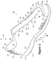
- the footwear 100 can generally include a sole structure 110 and an upper 120.
- Sole structure 110 is secured to upper 120 and extends between the foot and the ground when footwear 100 is worn.
- the sole structure 110 can include a midsole 112 and an outsole 114 that are layered on each other.
- the midsole 112 can include a resiliently compressible material, fluid-filled bladders, and the like. As such, the midsole 112 can cushion the wearer's foot and attenuate impact and other forces when running, jumping, and the like.
- the outsole 114 can be secured to the midsole 112 and can include a wear resistant material, such as rubber and the like.
- the outsole 114 can also include tread and other traction-enhancing features.
- the upper 120 can define a void 122 that receives a foot of the wearer. Stated differently, the upper 120 can define an interior surface 121 that defines the void 122, and the upper 120 can define an exterior surface 123 that faces in a direction opposite the interior surface 121. When the wearer's foot is received within the void 122, the upper 120 can at least partially enclose and encapsulate the wearer's foot.
- footwear uppers are formed from multiple material elements (e.g., textiles, polymer foam, polymer sheets, leather, synthetic leather) that are joined through stitching or bonding, for example.
- at least a portion of upper 120 is formed from a knitted component 116 having a unitary knit construction.
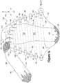
- the outer boundaries of the knitted component 116 can be defined by a peripheral edge 199, which is shown in FIGS. 5 and 6 .
- knitted component 116 can define at least a portion of the void within upper 120.
- the knitted component 116 can define at least a portion of the exterior surface 123 and/or the interior surface 121 of the upper 120.
- the knitted component 116 can define a majority of the upper 120. Decreasing the number of material elements used in forming the upper 120 may decrease waste, while also increasing the manufacturing efficiency and recyclability of the upper 120. As discussed in greater detail below, the knitted component 116 of the upper 120 of the present disclosure can decrease waste and increase manufacturing efficiency and recyclability. Additionally, the knitted component 116 of the upper 120 can incorporate smaller numbers of seams or other discontinuities, thereby enhancing the overall comfort of footwear 100.
- the knitted component 116 may also have common properties when formed from the same strand, yarn (or type of yarn) or with similar knit structures. For example, using the same strand in various portions of the knitted component 116 can impart similar durability, strength, stretch, wear-resistance, biodegradability, thermal, and hydrophobic properties. In addition to physical properties, using the same strand in multiple portions of the knitted component 116 can impart common aesthetic or tactile properties, such as color, sheen, and texture. Using the same knit structures across different portions of the knitted component 116 may also impart common physical properties and aesthetic properties.
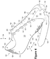
- FIGS. 4-6 illustrate various embodiments of knitted components 116 that may be incorporated into articles of footwear in a similar manner as the exemplary embodiment of FIGS. 1 through 3 .
- the knitted component 116 illustrated in FIGS. 4-6 are depicted separate from a remainder of footwear 100. However, it should be understood that each of the embodiments of knitted component 116 described herein may be combined with the elements of footwear 100, described above, to form an article of footwear 100 incorporating the knitted component 116.
- the knitted component 116 is of "unitary knit construction.” As defined herein and as used in the claims, the term “unitary knit construction” means that the knitted component 116 is formed as a one-piece element through a knitting process. That is, the knitting process substantially forms the various features and structures of knitted component 116 without the need for significant additional manufacturing steps or processes.
- a unitary knit construction may be used to form a knitted component having structures or elements that include one or more courses of yarn or other knit material that are joined such that the structures or elements include at least one course in common (i.e., sharing a common strand or common yarn) and/or include courses that are substantially continuous between each portion of the knitted component 116. With this arrangement, a one-piece element of unitary knit construction is provided.
- knitted component 116 Although portions of knitted component 116 may be joined to each other following the knitting process, knitted component 116 remains formed of unitary knit construction because it is formed as a one-piece knit element. Moreover, knitted component 116 remains formed of unitary knit construction when other elements (e.g., an inlaid strand, a closure element, logos, trademarks, placards with care instructions and material information, and other structural elements) are added following the knitting process.
- elements e.g., an inlaid strand, a closure element, logos, trademarks, placards with care instructions and material information, and other structural elements
- FIGS. 4-6 illustrate exemplary embodiments of the knitted component 116 as defining a majority of the upper 120 of the article of footwear 100.
- the knitted component 116 of the upper 120 can include a base portion 124 or strobel portion or underfoot portion.
- the knitted component 116 can include one or more side portions 126.
- the base portion 124 can be configured to be disposed adjacent the sole structure 110.
- the base portion 124 can attach directly or indirectly to the sole structure 110 such that the base portion 124 lies over the sole structure 110.
- one or more parts of the base portion 124 e.g., a periphery of the base portion 124) can attach to the sole structure 110 while other parts remain detached or decoupled.
- the base portion 124 can be configured to extend underneath the wearer's foot.
- the side portion(s) 126 can extend from the base portion 124 and can be configured to at least partially cover over the wearer's foot.
- the base portion 124 and side portion(s) 126 can cooperate to define a void 122 that receives the wearers foot.
- the base portion 124 and the side portion(s) 126 can be formed of a unitary knit construction as discussed above.
- the side portions 126 of the knitted component 116 can include a heel portion 128, a lateral portion 130, a medial portion 132, a forefoot portion 134, and a tongue portion 136, each of which are formed of the same unitary knit construction as the base portion 124.
- the knitted component 116 can fit and conform closely to the wearer's foot. Also, because of this construction, the knitted component 116 can be formed relatively quickly to increase manufacturing efficiency.
- the knitted component 116 can include one or more tensile strands 158 that are incorporated with the unitary knit construction of the knitted component 116.
- the strands 158 can be inlaid within the courses and/or wales of the knitted component 116 as will be discussed.
- the strands 158 can be attached to the interior and/or exterior surface of the knitted component 116.
- the strand(s) 158 can be disposed in the upper to extend across the sides and/or under the wearer's foot. Also, the strand(s) 158 can be operably coupled to a closure member 154, such as a shoelace 155. Thus, tensioning the shoelace 155 can, in turn, tension the strand(s) 158. As a result, the strand(s) 158 can provide support to the wearer's foot for increased comfort and better fit.
- the illustrated embodiments of the upper 120 and the footwear 100 is configured to be worn on a left foot of the wearer. However, it will be appreciated that the footwear 100 can be configured to be worn on the right foot and can include similar features as the illustrated embodiments.
- the footwear 100 can also be configured as a running shoe.
- the footwear 100 may also be applied to a variety of other athletic footwear types, including baseball shoes, basketball shoes, cycling shoes, football shoes, tennis shoes, soccer shoes, training shoes, walking shoes, and hiking boots, for example.
- the concepts may also be applied to footwear types that are generally considered to be non-athletic, including dress shoes, loafers, sandals, and work boots. Accordingly, the concepts disclosed with respect to footwear 100 apply to a wide variety of footwear types.
- the primary element of knitted component 116 may be formed from at least one yarn 1138 or other strand that is manipulated (e.g., with a knitting machine) to form a plurality of intermeshed loops that define a variety of courses and wales.
- yarn 1138 forms each of the courses and wales in this configuration, additional yarns may form one or more of the courses and/or wales.
- Cotton provides a soft hand, natural aesthetics, and biodegradability.
- Elastane and stretch polyester each provide substantial stretch and recovery, with stretch polyester also providing recyclability.
- Rayon provides high luster and moisture absorption.
- Wool also provides high moisture absorption, in addition to insulating properties and biodegradability.
- Nylon is a durable and abrasion-resistant material with relatively high strength.
- Polyester is a hydrophobic material that also provides relatively high durability.
- knitted component 116 includes yarn 1138 and another yarn 1139 (i.e., plural strands).
- Yarns 1138 and 1139 are plated and cooperatively form a plurality of intermeshed loops defining multiple horizontal courses and vertical wales. That is, yarns 1138 and 1139 run parallel to each other.
- An advantage of this configuration is that the properties of each of yarns 1138 and 1139 may be present in this area of knitted component 1130.
- yarns 1138 and 1139 may have different colors, with the color of yarn 1138 being primarily present on a face of the various stitches in knit element 1131 and the color of yarn 1139 being primarily present on a reverse of the various stitches in knit element 1131.
- yarn 1139 may be formed from a yarn that is softer and more comfortable against the foot than yarn 1138, with yarn 1138 being primarily present on first surface 1136 and yarn 1139 being primarily present on second surface 1137.
- a strand 1132 can be incorporated in the unitary knit construction of the knitted component 116.
- the strand 1132 can be a tensile strand element that provides support to the knitted component 116. Stated differently, tension within the strand 1132 can allow the knitted component 116 to resist deformation, stretching, or otherwise provide support for the wearer's foot during running, jumping, or other movements of the wearer's foot.
- the strand 158 of FIG. 6 (mentioned above and described in detail below) can be incorporated in the knitted component 116 similar to the strand 1132 of FIGS. 13 and 14 .
- the strand 1132 can be incorporated or inlaid into the unitary knit construction of the knitted component 116 such that the strand 1132 can be incorporated during the knitting processes on the knitting machine.
- the strand 1132 can be inlaid within the unitary knit construction such that the strand 1132 extends along one of the courses as shown in FIGS. 13 and 14 and/or the wales of the knitted component 116.
- the strand 1132 and can alternate between being located (a) behind loops formed from yarn 1138 and (b) in front of loops formed from yarn 1138. In effect, inlaid strand 1132 weaves through the unitary knit construction of knit element 1131.
- the knitted component may also include one or more strands or yarns that are formed from at least one of a thermoset polymer material and natural fibers (e.g., cotton, wool, silk). Other yarns or strands may be formed from a thermoplastic polymer material.
- a thermoplastic polymer material melts when heated and returns to a solid state when cooled. More particularly, the thermoplastic polymer material transitions from a solid state to a softened or liquid state when subjected to sufficient heat, and then the thermoplastic polymer material transitions from the softened or liquid state to the solid state when sufficiently cooled. As such, thermoplastic polymer materials are often used to join two objects or elements together.
- yarn may be utilized to join (a) one portion of yarn to another portion of yarn, (b) yarn and inlaid strand to each other, or (c) another element (e.g., logos, trademarks, and placards with care instructions and material information) to knitted component, for example.
- yarn may be considered a fusible yarn given that it may be used to fuse or otherwise join portions of knitted component to each other.
- yarn may be considered a non-fusible yarn given that it is not formed from materials that are generally capable of fusing or otherwise joining portions of knitted component to each other. That is, yarn may be a non-fusible yarn, whereas other yarn(s) may be a fusible yarn.
- yarn i.e., the non-fusible yarn
- yarn may be substantially formed from a thermoset polyester material and yarn (i.e., the fusible yarn) may be at least partially formed from a thermoplastic polyester material.
- the use of plated yarns may impart advantages to knitted component.
- this process may have the effect of stiffening or rigidifying the structure of knitted component.
- joining (a) one portion of yarn to another portion of yarn or (b) yarn and inlaid strand to each other has the effect of securing or locking the relative positions of yarn and inlaid strand, thereby imparting stretch-resistance and stiffness. That is, portions of yarn may not slide relative to each other when fused with yarn, thereby preventing warping or permanent stretching of knit element due to relative movement of the knit structure.
- Another benefit relates to limiting unraveling if a portion of knitted component becomes damaged or one of yarns is severed. Accordingly, areas of knitted component may benefit from the use of both fusible and non-fusible yarns within knit element.
- the knitted component can have varying zones that collectively form the unitary knit construction.
- the knitted component can include a combination at least two of the following: a flat knit zone, a tubular knit zone, a 1x1 mesh knit zone, a 2x2 mesh knit zone, a 3x2 mesh knit zone, a 1x1 mock mesh knit zone, a 2x2 mock mesh knit zone, a 2x2 hybrid knit zone, a full gauge knit zone, a 1 ⁇ 2 gauge knit zones, and the like.
- the knitted component 116 and upper 120 can be constructed according to the teachings of U.S. Patent Publication No. 2012/0233882 , which published on September 20, 2012.
- the upper 120 can define a longitudinal direction 125, a transverse direction 127, and a vertical direction 129, which will be used for referencing different features of the upper 120 in the below discussion.
- the knitted component 116 of the upper 120 can include a base portion 124, which is configured to be disposed underneath the wearer's foot.
- An outline of the wearer's foot is shown in FIG. 6 , such that the base portion 124 is at least generally defined relative to the wearer's foot.
- the base portion 124 can extend continuously underneath one or more portions of the heel, the sole, the toes, the arch, and/or other inferior surfaces of the wearer's foot.
- the base portion 124 can include openings and so as to extend partially or discontinuously under the wearer's foot
- the knitted component 116 can also include various side portions 126 that extend peripherally from the base portion 124.
- the side portions 126 can be configured to cover over and lie against at least a portion of the wearer's foot.
- the side portions 126 of the knitted component 116 can substantially encompass the base portion 124.
- the base portion 124 and the side portions 126 can collectively define the interior surface 121 of the knitted component 116 as well as the exterior surface 123 of the knitted component 116.
- the side portions 126 can include a heel portion 128, which is disposed on one end of the base portion 124.
- the heel portion 128 can also extend upwards from the base portion 124 in the vertical direction 129 as shown in FIG. 4 .
- the heel portion 128 can be configured to cover over a heel and/or an ankle area of the wearer's foot.
- the side portions 126 of the knitted component 116 can also include a lateral portion 130, which is disposed forward relative to the heel portion 128, and which can extend upwards from a lateral side of the base portion 124 as shown in FIG. 4 .
- the lateral portion 130 can be configured to cover over and lie against a lateral area of the wearer's foot.
- the side portions 126 of the knitted component 116 can include a medial portion 132, which is disposed on an opposite side of the base portion 124 relative to the lateral portion 130 and forward of the heel portion 128.
- the medial portion 132 can further extend upwards in the vertical direction 129 from the base portion 124 as shown in FIG. 4 .
- the media! portion 132 can be disposed on an opposite side of the base portion 124 in the transverse direction 127.
- the medial portion 132 can be configured to cover over and lie against a medial area or instep of the wearer's foot.
- the heel portion 128, lateral portion 130, and medial portion 132 can collectively define a horseshoe-shaped collar 133 of the upper 120.
- the collar 133 can provide access into and out of the void 122 of the upper 120.
- a lateral edge 135 of the lateral portion 130 and a medial edge 137 of the medial portion 132 can collectively define a throat 131 of the upper 120.
- the throat 131 can extend substantially parallel to the longitudinal direction 125, or the throat 131 can be disposed at an angle relative to the longitudinal direction 125. Also, although the throat 131 is substantially centered over the base portion 124 in the embodiments of FIG. 4 , the throat 131 can be disposed to one side relative to the base portion 124 in the transverse direction 127.
- the width of the throat 131 can be selectively varied by the closure member 154 so as to move the lateral and medial edges 135, 137 toward and away from each other.
- the footwear 100 can be selectively tightened on the wearer's foot and loosened from the wearer's foot.
- the side portions 126 of the knitted component 116 can include a forefoot portion 134.
- the forefoot portion 134 can be disposed on an opposite end of the base portion 124 relative to the heel portion 128 and forward of the lateral and medial portions 130, 132 in the longitudinal direction 125 as shown in FIG. 1 .
- the forefoot portion 134 can be integrally connected to either the lateral portion 130 or the medial portion 132, and the forefoot portion 134 can be spaced from the other.
- the forefoot portion 134 is integrally connected to the lateral portion 130 and is spaced from the medial portion 132. Accordingly, when the upper 120 is in a disassembled state as shown in FIG. 4 , a gap 139 can be defined between the forefoot portion 134 and the medial portion 132.
- the side portions 126 of the knitted component 116 can include a tongue portion 136.
- the tongue portion 136 can include a curved region 143 and a longitudinal region 145.
- the tongue portion 136 extends generally forward from the base portion 124, and the curved region 143 can be disposed within the gap 139 between the medial and forefoot portions.
- the curved region 143 can also curve such that the longitudinal region 145 extends generally rearwardly and at an angle 143 relative to the medial portion 132 as shown in FIG. 4 .
- the curvature of the curved region 143 can be achieved by having knit courses that substantially radiate from a common area 151 as shown in FIG.
- the common area 151 can be an imaginary point that is spaced from the periphery of the curved region 143, between the tongue portion 136 and the medial portion 132 as shown, or the common area 151 can be disposed elsewhere. Also, when the upper 120 is assembled, the curved region 143 can wrap upwards to at least partially fill the gap 139, and the longitudinal region 145 of the tongue portion 136 can be disposed within the throat 131 of the upper to cover over the wearers foot between the lateral portion 130 and the medial portion 132. Moreover, when the upper 120 is assembled, the longitudinal region 145 of the tongue portion 136 can be detached and decoupled from the lateral and/or medial portions 130, 132 as shown in FIG. 3 .
- the base portion 124 and the heel portion 128 can define a heel cavity 148 that is configured to receive a heel of the wearer's foot (see FIG. 6 ).
- the heel cavity 148 can have interior and/or exterior surfaces with three dimensional curvature.
- the heel cavity 148 can have a convex outer surface.
- the heel portion 128 can curve forward slightly in the longitudinal direction 125.
- both sides of the heel portion 128 can curve forward in the longitudinal direction 125 to join to the lateral and medial portions 130, 132. Accordingly, the heel cavity 148 can conform and approximately correspond to the shape of the wearer's heel and ankle.
- the base portion 124 and the forefoot portion 134 can define a forefoot cavity 150 that is configured to receive the toes and other forefoot regions of the wearer's foot (see FIG. 6 ).
- the forefoot cavity 150 can have interior and/or exterior surfaces with three dimensional curvature.
- the forefoot cavity 150 can have a convex outer surface.
- the forefoot portion 134 extends in the vertical direction 129 from the base portion 124, the forefoot portion 134 can curve rearwardly in the longitudinal direction 125.
- the forefoot portion 134 extends in the transverse direction 127, the forefoot portion 134 can curve rearwardly in the longitudinal direction 125 to join to the lateral portion 130.
- the three dimensional curvature of the heel cavity 148 and/or the forefoot cavity 150 can be formed due to the unitary knit construction of the knitted component 116.
- the heel portion 128 can include at least two tapered areas 170, 171.
- the tapered areas 170, 171 can have boundaries 173 that taper generally in the transverse direction 127 as indicated by broken lines.
- the tapered areas 170, 171 each have a plurality of courses, or row of stitches; however, the successive courses can have different lengths to thereby provide the tapered shape of the boundaries 173.
- the tapered areas 170, 171 can have an eye shape, a double pointed oval shape, a biconvex shape, or a crescent shape.
- the boundary 173 of the tapered area 170 is joined to the boundary 173 of the tapered area 171 in the unitary knit construction to provide the knitted component 116 with three dimensional curvature. This can produce a visually evident distortion along the joined boundaries 173.
- the distortion can be a so-called fully fashioned mark extending along the joined boundaries 173 in the knitted component 116.
- a majority of the heel portion 128 can have three-dimensional curvature.
- knitted component 116 can include any number of tapered areas 170, 171 on any portion of the knitted component 116 to provide three dimensional curvature to the knitted component 116.
- the tapered areas 170, 171 can be oriented in any suitable direction on the knitted component 116.
- the forefoot portion 134 can similarly include tapered areas; however, such tapered areas can taper in the vertical direction 129 in exemplary embodiments.
- the curved region 143 of the tongue portion 136 can also include a plurality of tapered areas that provide the curved region 143 with curvature.
- the curved region 143 can include tapered areas 193, 195 that are integrally knit together and joined along boundaries 197. This can produce a visually evident distortion along the joined boundaries 197.
- the distortion can be a so-called fully fashioned mark extending along the joined boundaries 197 in the knitted component 116.
- the courses within the curved region 143 can radiate from common area 151 to provide two-dimensional curvature.
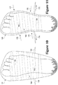
- the forefoot portion 134 can include a plurality of openings 152 that are arranged to assist with increasing curvature of the forefoot portion 134.
- the plurality of openings 152 can include one or more rows of through-holes. Because the openings 152 reduce the amount of knitted material at those areas of the forefoot portion 134, the forefoot portion 134 can readily curve rearward toward the heel portion 128.
- the knitted component 116 additionally includes at least two edge portions 140, 142 that are configured to be joined together when assembling the upper 120.
- the first edge portion 140 can be a first longitudinal section of larger peripheral edge 199 of the knitted component 116 shown in FIGS. 5 and 6 .
- the second edge portion 142 can be a second longitudinal section of the peripheral edge 199.
- the edge portions 140, 142 can be defined in any suitable location long the peripheral edge 199 and/or anywhere on the knitted component 116.
- the first edge portion 140 can extend along the curved region 143 of the tongue portion 136 and can also extend partially through the base portion 124 in the transverse direction 127, adjacent the forefoot portion 134.
- the second edge portion 142 can curve along the forefoot portion 134, generally in the transverse direction 127 and can extend downward in the vertical direction 129 along the forefoot portion 134 so as to partially define the gap 139.
- the first edge 140 and the second edge 142 can also meet at a notch 141 defined within the base portion 124 as shown in FIG. 4 .
- the footwear 100 can further include a closure member 154, which is illustrated in FIG. 1 .
- the closure member 154 can selectively secure the upper 120 to the wearer's foot and selectively release the upper 120 from the wearer's foot.
- the closure member 154 can be a shoelace 155.
- the lateral portion 130 can include one or more lateral closure openings 156, such as through-holes that are disposed in a row extending along the lateral edge 135.
- the medial portion 132 can include similar medial closure openings 157 that are disposed in a row extending along the medial edge 137.
- the openings 156, 157 can receive the shoelace 155 such that the shoelace 155 can criss-cross, zigzag, and alternate between the lateral and medial portions 130, 132.
- openings 156, 157 could be configured differently from the through-holes shown in FIG. 1 .
- the openings 156, 157 could be defined by hoops, grommets, hooks, and other suitable features that are configured to receive a closure member and that are either integrated into the knitted component 116 or are removably attached to the knitted component 116.
- closure member 154 could include structure other than the shoelace 155 without departing from the scope of the present disclosure.
- the closure member 154 could be a strap, a buckle, pile tape, or other suitable closure member.
- the upper 120 can include at least one tensile strand 158 that is coupled to the base portion 124 and/or the side portions 126.
- the strand 158 can be coupled to any portion of the base portion 124 and/or the side portion 126. Additionally, the strand 158 can be coupled to the base portion 124 and/or the side portion 126 in any suitable fashion. For instance, the strand 158 can be inlaid within courses and/or wales of the unitary knit construction of the base portion 124 and side portions 126 as will be discussed.
- the strand 153 can correspond to the strand 1132 described above and shown in FIGS. 13 and 14 .
- the strand 158 can also be adhered, fastened, pierced through, or otherwise coupled to the interior or exterior surfaces 121, 123 of the base portion 124 and/or the side portion 126.
- the strand 158, knitted component 116, and upper 120 can incorporate the teachings of one or more of commonly-owned U.S. Patent Application Serial Number 12/338,726 to Dua et al. , entitled “Article of Footwear Having An Upper Incorporating A Knitted Component", filed on December 18, 2008 and published as U.S. Patent Application Publication Number 2010/0154256 on June 24, 2010 , and U.S. Patent Application Serial Number 13/048,514 to Huffa et al. , entitled “Article Of Footwear Incorporating A Knitted Component", filed on March 15, 2011 and published as U.S. Patent Application Publication Number 2012/0233882 on September 20, 2012 (collectively referred to herein as the "Inlaid Strand cases").
- the strand 158 can be an elongate and flexible. Also, the strand 158 can include at least one yarn, cable, wire, string, cord, filament, fiber, thread, rope, and the like. Also, the strand 158 can be formed from rayon, nylon, polyester, polyacrylic, silk, cotton, carbon, glass, aramids (e.g., para-aramid fibers and meta-aramid fibers), ultra high molecular weight polyethylene, liquid crystal polymer, copper, aluminum, steel, or other suitable material.
- An individual filament utilized in the strand 158 may be formed form a single material (i.e., a monocomponent filament) or from multiple materials (i.e., a bicomponent filament). Similarly, different filaments may be formed from different materials.
- yarns utilized as strand 158 may include filaments that are each formed from a common material, may include filaments that are each formed from two or more different materials, or may include filaments that are each formed from two or more different materials. Similar concepts also apply to threads, cables, ropes, etc.
- the thickness (diameter) of strand 158 can be within a range from approximately 0.03 millimeters to 5 millimeters, for example.
- the strand 158 can have a substantially circular cross section, an ovate cross section, or a cross section of any other suitable shape.
- the strand 158 may be formed from a bonded nylon 6.6 with a breaking or tensile strength of 3.1 kilograms and a weight of 45 tex.
- the strand 158 can also be formed from a bonded nylon 6.6 with a breaking or tensile strength of 6.2 kilograms and a tex of 45.
- the strand 158 may have an outer sheath that sheathes and protects an inner core.
- the strand 158 can have a fixed length (e.g., can be nonextendible). Also in some embodiments, the strand 158 can be resiliently extendible.
- the strand 158 can include a thermoplastic material that is configured to adhere, bond, or fuse to the base portion 124 and/or the side portions 126 of the upper 120. For instance, selective application of heat can cause materials in the strand 158 to fuse to the materials of the base portion 124 and/or the side portions 126.
- the strand 158 can, thus, be included according to the teachings of U.S. Patent Publication No. 2012/0233882, which published on September 20, 2012 .
- the upper 120 can include a single strand 158 that extends continuously between the medial portion 132, the base portion 124, and the lateral portion 130.
- the strand 158 can include one or more turns 159, 160.
- the turns 159, 160 can be one hundred eighty degree turns or greater.
- the strand 158 can include a plurality of lateral turns 159 that are arranged in a row along the lateral edge 135, and the strand 158 can include a plurality of medial turns that are arranged in a row along the medial edge 137.
- the strand 158 can also extend linearly between pairs of the turns 159, 160.
- the strand 158 can include a first terminal end 164 that is disposed adjacent the heel portion 128, and the strand 158 can include a second terminal end 166 that is disposed adjacent the forefoot portion 134.
- the strand 158 can also alternatingly extend and zigzag between the lateral and medial portions 130, 132.
- the knitted component 116 can define a passage 162 between the interior surface 121 and the exterior surface 123.
- the passage 162 can be defined in any suitable fashion.
- the passage 162 can be defined through one or more courses or wales of the knitted component 116.
- the interior surface 121 can be defined by a layer of knitted material and the exterior surface 123 can be defined by a separate layer of knitted material, and a plurality of strands, filaments, or monofilaments can extend and provide spacing between these layers (e.g., a so-called "spacer knit material").
- the passage 162 can be defined between the layers of knitted material and among the plurality of spacer strands.
- the interior surface 121 and the exterior surface 123 can be interconnected stitched surfaces, and the passage 162 can be defined between these surfaces.
- the passage 162 can extend across any portion of the upper 120.
- the upper 120 can define a plurality of passages 162, and each passage 162 can extend continuously between the lateral portion 130, the base portion 124, and the media! portion 132.
- each passage 162 extends partially across the lateral portion 130 (lateral passage), partially across the base portion 124 (base portion passage), and partially across the medial portion 132 (medial passage) such that the passage 162 is continuous between the lateral portion 130, the base portion 124, and the medial portion 132.
- one or more passage 162 can be localized and isolated on any portion of the upper 120.
- the strand 158 can be received and can extend longitudinally within one or more of the passages 162 so as to extend between the lateral portion 130, the base portion 124, and the medial portion 132. Also, the turns 159, 160 of the strand 158 can be exposed from the passages 162.
- the lateral turns 159 can extend at least partially around respective ones of the lateral closure openings 156, and the medial turns 160 can extend at least partially around respective ones of the medial closure openings 157. Furthermore, as shown in FIG. 1 , the shoelace 155 can be received within respective pairs of the lateral closure openings 156 and the lateral turns 159, and the shoelace 155 can also be received within respective pairs of the medial closure openings 157 and the medial turns 160. Stated differently, each pairing of lateral turn 159 and lateral closure opening 156 can cooperatively receive and support the shoelace 155, and each pairing of medial turn 160 and medial closure opening 157 can also receive and support the shoelace 155.
- the strand 158 can be loosely and moveably received within the respective passages 162. For instance, the strand 158 can slide longitudinally through the passages 162. Thus, as shown in FIG. 9 , the turns 159, 160 can be pulled closer to the respective closure opening 156, 157.
- the first and/or the second terminal end 164, 166 of the strand 158 can be fixed (e.g., fused) to the base portion 124 while remaining portions of the strand 158 can remain moveable relative to the base, lateral, and medial portions 124, 130, 132.
- portions of the strand 158 between the terminal ends 164, 166 can be fused or otherwise fixed to the base, lateral, and medial portions 124, 130, 132.
- tensioning the shoelace 155 can, in turn, increase tension in the strand 158.
- tension in the strand 158 can be relatively low, thereby allowing the upper 120 to fit loosely about the wearer's foot.
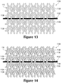
- the shoelace 155 is pulled and tensioned as indicated by arrows 174, 175, the shoelace 155 can pull on the turns 159, 160 to increase tension in the strand 158.
- the strand 158 can pull and conform the upper 120 closely to the wearer's foot as indicated by arrows 176, 177, 178, 179 in FIG. 11 .
- the strand 158 can provide support for various areas on the bottom of the wearer's foot.
- the strand 158 can be disposed on an arch region 164 that is configured to be disposed underneath the arch of the wearer's foot.
- the strand 158 within the arch region 164 can support the wearers arch, especially when the strand 158 is tensioned by the shoelace 155.
- the upper 120 can include only one continuous strand 158 for providing such support to the foot. Accordingly, the part count of the upper 120 can be relatively low, and the upper 120 can be constructed in an efficient manner.
- the lateral and media! portions 130, 132 can be moved (folded) superiorly to the position shown in FIG. 4 . Then, the tongue portion 136 can be wrapped superiorly such that the curved region 143 substantially fills the gap 139 and the longitudinal region 145 substantially fills the throat 131. As such, the first and second edge portions 140, 142 can be disposed directly adjacent each other. Then, the first and second edge portions 140, 142 can be joined at a seam 144.
- the first and second edge portions 140, 142 can be joined at the seam 144 in any suitable fashion.
- the first and second edge portions 140, 142 can be joined using stitching, adhesives, tape, bonding, welding, fasteners, or other suitable attachment devices.
- the seam 144 can be formed by stitching the edge portions 140, 142 together with stitching 146 as shown in FIGS. 1-3 .
- the upper 120 can be a knitted element with a plurality of stitches; however, it will be appreciated that the stitching 146 can be independent of the stitches of the knitted component 116. Stated differently, the stitching 146 can be formed using one or more threads, yarns, cables, or other strands that are attached after the knitted component 116 has been knitted.
- the stitching 146 can also be a zigzag stitch or other suitable stitch. Additionally, the edge portions 140, 142 can abut at the seam 144.
- edge portions 140, 142 can form a butt joint, or the edge portions 140, 142 can be partially overlapped to form the seam 144. Additionally, the edge portions 140, 142 can be slightly spaced apart at the seam 144 with a bead of adhesive or other material between the edge portions 140, 142 at the seam 144.
- the seam 144 can extend across any suitable portion of the knitted component 116.
- the seam 144 can include a first terminal end 147 disposed in the base portion 124, adjacent the forefoot portion 134.
- the seam 144 can also include a second terminal end 149 at the junction of the lateral edge 135, the forefoot portion 134, and the tongue portion 136.
- the seam 144 can extend continuously between the first and second terminal ends 147, 149 in some embodiments.
- the seam 144 can include a first portion 181 that extends across the base portion 124 generally in the transverse direction 127 toward the medial portion 132 from the first terminal end 147.
- the seam 144 can also include a second portion 183 that extends generally in the vertical direction 129 across the medial portion 132 and adjacent the forefoot portion 134.
- the seam 144 can further include a third portion 185 that extends generally in the transverse direction toward the lateral side 130 and that curves rearwardly toward the second terminal end 149.
- the seam 144 can extend continuously between the ends 147, 149 so as to extend from under the wearer's foot, around a medial area of the wearer's forefoot, to an area above the wearer's forefoot.
- seams 144 of the knitted component 116 there can be any number of seams 144 of the knitted component 116. As shown in the embodiments of FIG. 3 , for instance, there can be only one, solitary seam 144 necessary for giving the knitted component 116 of the upper 120 the three dimensional shape shown in FIGS. 1-3 . This can facilitate manufacturing and reduce time for assembly of the upper 120.
- the seam 144 can be spaced from the heel portion 128 such that the heel portion 128 is seamless.
- the relatively smooth and seamless heel portion 128 is unlikely to rub on the wearers heel and provide discomfort to the wearer.
- the shoelace 155 can be threaded through the lateral and medial openings 156, 157 and the lateral and medial turns 159, 160 as discussed above.
- the sole structure 110 can be attached to the upper 120.
- the midsole 112 can be attached to the exterior surface 123 of the base portion 124, and the outsole 114 can be attached to the midsole 112.
- an additional sockliner can be inserted over and/or attached to the interior surface 121 of the base portion 124.
- FIG. 12 Additional embodiments of the knitted component 116 of the upper 220 are illustrated in FIG. 12 .
- the knitted component 116 and upper 220 can be substantially similar to the knitted component 116 and upper 120 described above, except as discussed.
- the upper 220 can include a strand 258 that alternatingly extends across the medial portion 232, the base portion 224, and the lateral portion 230, similar to the embodiments discussed above.
- the strand 258 can also extend through one or more passages 262.
- the passages 262 can be defined on the medial portion 132 and the lateral portion 130, and the passages 262 can be spaced away from the base portion 224.
- longitudinal portions of the strand 258 extending across the base portion 224 can be exposed from the passages 262. Also, these portions of the strand 258 can be detached and decoupled from the base portion 224. Thus, in some embodiments, these portions of the strand 258 can be free to be attached directly to the sole structure 110.
- the passages 262 can be V-shaped such that the turns of the strand 258 are embedded and enclosed within the passages 262 unlike the exposed turns 159, 160 shown above in FIGS. 1-6 .
- the knitted component 116 can be knitted in any suitable direction.
- the knitted component 116 can be formed from the heel portion 128, at the collar 133, and the knitted component 116 can be formed so as to grow generally in the lontidudinal direction 125 toward the forefoot portion 134.
- the forefoot cavity 150 can be formed before the tongue portion 136.
- the tongue portion 136 can be subsequently formed.
- the three dimensionally curved cavities and the two dimensionally curved portions of the knitted component 116 (such as the heel cavity 148, the forefoot cavity 150, the curved region 143 and/or other areas) can be formed unitarily during the knitting process.
- the stitches at the boundaries 173, 197 can be held by respective needles as subsequent courses of stitches are added, and the held stitches at the boundaries 173, 197 can be knitted to respective stitches across the boundaries 173, 197.
- the strand 158 can be inlaid during this knitting process. Also, this process can be completed on any suitable machine, such as a flat knitting machine.
- knitted component 116 with the strand 158 will be discussed.
- flat knitting processes and flat knitting machines will be discussed, however, the knitted component 116 and strand 158 can be otherwise formed without departing from the scope of the present disclosure.
- the knitted component 116 and strand 158 can be formed according to the teachings of U.S. Patent Publication No. 2012/0233882, which published September 20, 2012 .
- a portion of knitting machine 1200 that includes various needles 1202, rail 1203, standard feeder 1204, and combination feeder 1220 is depicted.
- combination feeder 1220 is secured to a front side of rail 1203
- standard feeder 1204 is secured to a rear side of rail 1203.
- Yarn 1206 passes through combination feeder 1220, and an end of yarn 1206 extends outward from dispensing tip 1246.
- any other strand e.g., filament, thread, rope, webbing, cable, chain, or yarn
- Another yarn 1211 passes through standard feeder 1204 and forms a portion of a knitted component 1260, and loops of yarn 1211 forming an uppermost course in knitted component 1260 are held by hooks located on ends of needles 1202.
- the knitting process discussed herein relates to the formation of knitted component 1260 or portion of knitted component 1260.
- the portion of the knitted component 1260 can correspond to the base portion 124, the heel portion 128, the lateral portion 130, the medial portion 132, the forefoot portion 134, and/or the tongue portion 136 discussed above in relation to FIGS. 1-6 .
- only a relatively small section of knitted component 1260 is shown in the figures in order to permit the knit structure to be illustrated.
- the scale or proportions of the various elements of knitting machine 1200 and knitted component 1260 may be enhanced to better illustrate the knitting process.
- standard feeder 1204 moves along rail 1203 and a new course is formed in knitted component 1260 from yarn 1211. More particularly, needles 1202 pulled sections of yarn 1211 through the loops of the prior course, thereby forming the new course. Accordingly, courses may be added to knitted component 1260 by moving standard feeder 1204 along needles 1202, thereby permitting needles 1202 to manipulate yarn 1211 and form additional loops from yarn 1211.
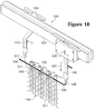
- feeder arm 1240 now translates from the retracted position to the extended position, as depicted in FIG. 17 .
- feeder arm 1240 extends downward from carrier 1230 to position dispensing tip 1246 in a location that is (a) centered between needles 1202 and (b) below the intersection of needle beds.
- combination feeder 1220 moves along rail 1203 and yarn 1206 is placed between loops of knitted component 1260. That is, yarn 1206 is located in front of some loops and behind other loops in an alternating pattern. Moreover, yarn 1206 is placed in front of loops being held by needles 1202 from one needle bed 1201, and yarn 1206 is placed behind loops being held by needles 1202 from the other needle bed. Note that feeder arm 1240 remains in the extended position in order to inlay yarn 1206 in the area below the intersection of needle beds. This effectively places yarn 1206 within the course recently formed by standard feeder 1204 in FIG. 16 .
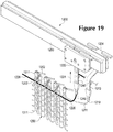
- standard feeder 1204 moves along rail 1203 to form a new course from yarn 1211, as depicted in FIG. 19 .
- yarn 1206 is effectively knit within or otherwise integrated into the structure of knitted component 1260.
- feeder arm 1240 may also translate from the extended position to the retracted position.
- FIGS. 18 and 19 show separate movements of feeders 1204 and 1220 along rail 1203. That is, FIG. 18 shows a first movement of combination feeder 1220 along rail 1203, and FIG. 19 shows a second and subsequent movement of standard feeder 1204 along rail 1203.
- feeders 1204 and 1220 may effectively move simultaneously to inlay yarn 1206 and form a new course from yarn 1211.
- Combination feeder 1220 moves ahead or in front of standard feeder 1204 in order to position yarn 1206 prior to the formation of the new course from yarn 1211.
- the general knitting process outlined in the above discussion provides an example of the manner in which strand 158 of FIGS. 1-6 may be located in the base portion 124, the lateral portion 130, and/or the medial portion 132 of the upper 120. More particularly, because of the reciprocating action of feeder arm 1240, the strand 158 may be located within a previously formed course prior to the formation of a new course.
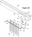
- feeder arm 1240 now translates from the retracted position to the extended position, as depicted in FIG. 20 .
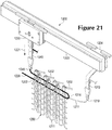
- Combination feeder 1220 then moves along rail 1203 and yarn 1206 is placed between loops of knitted component 1260, as depicted in FIG. 21 .
- standard feeder 1204 moves along rail 1203 to form a new course from yarn 1211, as depicted in FIG. 22 .
- yarn 1206 is effectively knit within or otherwise integrated into the structure of knitted component 1260.
- feeder arm 1240 may also translate from the extended position to the retracted position.
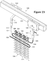
- yarn 1206 forms a loop 1214 between the two inlaid sections.
- strand 158 exits the passage 162 and then enters another passage 162, thereby forming the turns 159, 160.
- Loop 1214 can be formed in a similar manner. That is, loop 1214 can be formed where yarn 1206 exits the knit structure of knitted component 1260 and then re-enters the knit structure.
- combination feeder 1220 moves along rail 1203 while in the retracted position and forms a course of knitted component 1260 while in the retracted position. Accordingly, by reciprocating feeder arm 1240 between the retracted position and the extended position, combination feeder 1220 may supply yarn 1206 for purposes of knitting, tucking, floating, and inlaying.
Claims (15)
- Tige (120, 220) pour article chaussant (100), laquelle est réalisée de manière à être reliée à une structure de semelle (110) et est réalisée de manière à recevoir un pied, la tige (120, 220) comportant :un composant tricoté (116, 1130) comprenant une unité d'une seule pièce d'un ensemble tricoté unitaire, et comportant :un tronçon de base (124, 224) qui est réalisé de manière à être agencé adjacent à la structure de semelle (110),un tronçon de talon (128) et un tronçon d'avant-pied (134) qui s'étendent à partir d'extrémités opposées du tronçon de base (124, 224),un tronçon médian (132, 232) et un tronçon latéral (130, 230) qui s'étendent à partir de côtés opposés du tronçon de base (124, 224), le tronçon médian (132, 232) et le tronçon latéral (130, 230) coopérant pour définir une zone d'étranglement entre le tronçon médian (132, 232) et le tronçon latéral (130, 230),la tige étant caractérisée en ce que le composant tricoté (116, 1130) comprenant une unité d'une seule pièce d'un ensemble tricoté unitaire comprend en outre :un tronçon de languette (136) qui est réalisé de manière à être agencé dans la zone d'étranglement, le tronçon de languette (136) étant découplé du tronçon médian (132, 232) et/ou du tronçon latéral (130, 230) et s'étendant à partir du tronçon de base (124, 224) ;une première arête (140) du composant tricoté (116, 1130) ;
etune deuxième arête (142) du composant tricoté (116, 1130) qui est réalisée de manière à être raccordée à la première arête (140) au niveau d'une couture (144), amenant le tronçon de base (124, 224), le tronçon de talon (128), le tronçon d'avant-pied (134), le tronçon médian (132, 232), le tronçon latéral (130, 230) et le tronçon de languette (136) à définir par coopération une cavité (122) qui est réalisée de manière à recevoir le pied. - Tige (120, 220) selon la revendication 1, le tronçon de talon (128) et/ou le tronçon d'avant-pied (134) comprenant une surface qui présente une courbure tridimensionnelle.
- Tige (120, 220) selon la revendication 1, un espace (139) étant défini entre le tronçon d'avant-pied (134) et le tronçon médian (132, 232) et/ou le tronçon latéral (130, 230), le tronçon de languette (136) étant agencé dans l'espace (139).
- Tige (120, 220) selon la revendication 1, le composant tricoté (116, 1130) comportant une première zone effilée (170) qui présente un premier bord effilé (173), et une deuxième zone effilée (171) qui présente un deuxième bord effilé (173), le premier bord effilé (173) étant joint au deuxième bord effilé (173) pour munir le composant tricoté (116, 1130) d'une surface à contour tridimensionnel.
- Tige (120, 220) selon la revendication 1, le tronçon de languette (136) comportant une zone courbe (143) qui présente une pluralité de rangées de mailles tricotées qui rayonnent à partir d'une zone commune (151) pour munir la zone courbe (143) d'une courbure.
- Tige (120, 220) selon la revendication 1, un cordon extensible (158) s'étendant de manière continue depuis le tronçon médian (132, 232), à travers le tronçon de base (124, 224) vers le tronçon latéral (130, 230).
- Tige (120, 220) selon la revendication 6, le cordon extensible comportant un virement (159) qui est réalisé de manière à recevoir et à supporter un élément de fermeture (155) qui fixe sélectivement la tige (120, 220) au pied.
- Tige (120, 220) selon la revendication 6, le tronçon de base (124, 224) définissant une surface intérieure (121) du composant tricoté (116, 1130) et une surface extérieure (123) du composant tricoté (116, 1130), un passage (162, 262) étant défini entre la surface intérieure (121) et la surface extérieure (123), et le cordon extensible (158) s'étendant à travers le passage (162, 262).
- Tige (120, 220) selon la revendication 1, la couture (144) étant espacée du tronçon de talon (128) de sorte que le tronçon de talon (128) est sans couture, et/ou la couture (144) étant la seule couture de la tige (120, 220).
- Article chaussant (100) comprenant la tige (120, 220) selon l'une des revendications 1 à 9.
- Procédé de fabrication d'un composant tricoté (116, 1130) comprenant une unité d'une seule pièce d'un ensemble tricoté unitaire pour un article chaussant (100) qui est réalisée de manière à être reliée à une structure de semelle (110), le procédé comprenant :le tricotage du composant tricoté (116, 1130) de sorte qu'il présenteun tronçon de base (124, 224) qui est réalisé de manière à être agencé adjacent à la structure de semelle (110),un tronçon de talon (128) et un tronçon d'avant-pied (134) qui s'étendent à partir d'extrémités opposées du tronçon de base (124, 224),un tronçon médian (132, 232) et un tronçon latéral (130, 230) qui s'étendent à partir de côtés opposés du tronçon de base (124, 224), le tronçon médian (132, 232) et le tronçon latéral (130, 230) coopérant pour définir une zone d'étranglement entre le tronçon médian (132, 232) et le tronçon latéral (130, 230),le procédé étant caractérisée en ce que le composant tricoté (116, 1130) comprend une unité d'une seule pièce d'un ensemble tricoté unitaire qui présente en outre :un tronçon de languette (136) qui est réalisé de manière à être agencé dans la zone d'étranglement, le tronçon de languette (136) étant découplé du tronçon médian (132, 232) et/ou du tronçon latéral (130, 230) et s'étendant à partir du tronçon de base (124, 224) ; etle raccordement d'une première arête (140) du composant tricoté (116, 1130) et d'une deuxième arête (142) du composant tricoté (116, 1130) au niveau d'une couture (144), amenant le tronçon de base (124, 224), le tronçon de talon (128), le tronçon d'avant-pied (134), le tronçon médian (132, 232), le tronçon latéral (130, 230) et le tronçon de languette (136) à définir par coopération une cavité (122) qui est réalisée de manière à recevoir le pied.
- Procédé selon la revendication 11, le tricotage du composant tricoté (116, 1130) comprenant la réalisation d'une surface d'une cavité qui présente une courbure tridimensionnelle.
- Procédé selon la revendication 11, comprenant en outre l'extension d'un cordon extensible (158) de manière continue à partir du tronçon médian (132, 232), à travers le tronçon de base (124, 224), vers le tronçon latéral (130, 230).
- Procédé selon la revendication 11, le tricotage du composant tricoté (116, 1130) comprenant le tricotage d'une première zone effilée (170) qui présente un premier bord effilé (173), et d'une deuxième zone effilée (171) qui présente un deuxième bord effilé (173), le premier bord effilé (173) étant joint au deuxième bord effilé (173) pour munir le composant tricoté (116, 1130) d'une surface à contour tridimensionnel.
- Procédé selon la revendication 11, le tricotage du composant tricoté (116, 1130) comprenant le tricotage du tronçon de languette (136) de sorte qu'il comporte une zone courbe (143) qui présente une pluralité de rangées de mailles tricotées qui rayonnent à partir d'une zone commune (151) pour munir la zone courbe (143) d'une courbure.
Applications Claiming Priority (2)
| Application Number | Priority Date | Filing Date | Title |
|---|---|---|---|
| US13/783,900 US9848672B2 (en) | 2013-03-04 | 2013-03-04 | Article of footwear incorporating a knitted component with integrally knit contoured portion |
| PCT/US2014/019548 WO2014137826A1 (fr) | 2013-03-04 | 2014-02-28 | Article de chaussure intégrant un élément tricoté ayant une partie profilée entièrement tricotée |
Publications (2)
| Publication Number | Publication Date |
|---|---|
| EP2964044A1 EP2964044A1 (fr) | 2016-01-13 |
| EP2964044B1 true EP2964044B1 (fr) | 2019-12-04 |
Family
ID=50678261
Family Applications (1)
| Application Number | Title | Priority Date | Filing Date |
|---|---|---|---|
| EP14722000.8A Active EP2964044B1 (fr) | 2013-03-04 | 2014-02-28 | Article de chaussure intégrant un élément tricoté ayant une partie profilée entièrement tricotée |
Country Status (10)
| Country | Link |
|---|---|
| US (1) | US9848672B2 (fr) |
| EP (1) | EP2964044B1 (fr) |
| JP (1) | JP6399524B2 (fr) |
| KR (1) | KR101844640B1 (fr) |
| CN (2) | CN107348615B (fr) |
| AR (1) | AR094988A1 (fr) |
| BR (1) | BR112015021759A8 (fr) |
| HK (1) | HK1214098A1 (fr) |
| TW (1) | TWI516217B (fr) |
| WO (1) | WO2014137826A1 (fr) |
Cited By (1)
| Publication number | Priority date | Publication date | Assignee | Title |
|---|---|---|---|---|
| US11553759B2 (en) | 2018-06-08 | 2023-01-17 | Decathlon | Method for producing a shoe and shoe that can be obtained by said method |
Families Citing this family (47)
| Publication number | Priority date | Publication date | Assignee | Title |
|---|---|---|---|---|
| US9498023B2 (en) | 2012-11-20 | 2016-11-22 | Nike, Inc. | Footwear upper incorporating a knitted component with sock and tongue portions |
| US9936757B2 (en) | 2013-03-04 | 2018-04-10 | Nike, Inc. | Article of footwear incorporating a knitted component with integrally knit contoured portion |
| US9848672B2 (en) | 2013-03-04 | 2017-12-26 | Nike, Inc. | Article of footwear incorporating a knitted component with integrally knit contoured portion |
| DE102013207156A1 (de) | 2013-04-19 | 2014-10-23 | Adidas Ag | Schuh, insbesondere ein Sportschuh |
| DE102013207155B4 (de) | 2013-04-19 | 2020-04-23 | Adidas Ag | Schuhoberteil |
| US11666113B2 (en) * | 2013-04-19 | 2023-06-06 | Adidas Ag | Shoe with knitted outer sole |
| DE102013207163B4 (de) | 2013-04-19 | 2022-09-22 | Adidas Ag | Schuhoberteil |
| US10299531B2 (en) * | 2013-05-14 | 2019-05-28 | Nike, Inc. | Article of footwear incorporating a knitted component for a heel portion of an upper |
| US9538803B2 (en) * | 2013-05-31 | 2017-01-10 | Nike, Inc. | Method of knitting a knitted component for an article of footwear |
| WO2014203584A1 (fr) * | 2013-06-17 | 2014-12-24 | 株式会社島精機製作所 | Empeigne de chaussure, et procédé de fabrication de celle-ci |
| JP6288743B2 (ja) * | 2013-09-13 | 2018-03-07 | ナイキ イノヴェイト シーヴィーNike Innovate C.V. | 一体化ニット輪郭部分を備えたニット構成要素を組み込んだ履物製品 |
| DE102014202432B4 (de) | 2014-02-11 | 2017-07-27 | Adidas Ag | Verbesserter Fußballschuh |
| EP3090083B1 (fr) * | 2014-03-04 | 2018-05-09 | Knitmaster LLC | Procédés de fabrication de composants de chaussures |
| US10383388B2 (en) * | 2014-03-07 | 2019-08-20 | Nike, Inc. | Article of footware with upper incorporating knitted component providing variable compression |
| US9510637B2 (en) * | 2014-06-16 | 2016-12-06 | Nike, Inc. | Article incorporating a knitted component with zonal stretch limiter |
| TW201607448A (zh) * | 2014-06-30 | 2016-03-01 | 島精機製作所股份有限公司 | 鞋面 |
| US9078488B1 (en) | 2014-09-30 | 2015-07-14 | Nike, Inc. | Article of footwear incorporating a lenticular knit structure |
| US10822728B2 (en) | 2014-09-30 | 2020-11-03 | Nike, Inc. | Knitted components exhibiting color shifting effects |
| US9192204B1 (en) * | 2014-09-30 | 2015-11-24 | Nike, Inc. | Article of footwear upper incorporating a textile component with tensile elements |
| US9375046B2 (en) | 2014-09-30 | 2016-06-28 | Nike, Inc. | Article of footwear incorporating a knitted component with inlaid tensile elements and method of assembly |
| DE102014220087B4 (de) | 2014-10-02 | 2016-05-12 | Adidas Ag | Flachgestricktes Schuhoberteil für Sportschuhe |
| TW201632094A (zh) * | 2014-12-25 | 2016-09-16 | 島精機製作所股份有限公司 | 鞋之編織方法、鞋之製造方法、及鞋 |
| CN107105817B (zh) * | 2015-01-16 | 2020-06-12 | 耐克创新有限合伙公司 | 包含鞋前部脚趾卷绕物的鞋类物品 |
| TWM534533U (zh) * | 2015-05-29 | 2017-01-01 | 耐基創新公司 | 以平坦鞋面製造的鞋 |
| WO2017044531A1 (fr) * | 2015-09-08 | 2017-03-16 | Avery Dennison Retail Information Services, Llc | Chaussure rétrécissable ou dispositif de chaussette |
| US9888742B2 (en) * | 2015-09-11 | 2018-02-13 | Nike, Inc. | Article of footwear with knitted component having plurality of graduated projections |
| USD794313S1 (en) * | 2015-12-01 | 2017-08-15 | Nike, Inc. | Shoe upper |
| WO2017123752A1 (fr) * | 2016-01-15 | 2017-07-20 | Nike Innovate C.V. | Procédé de fabrication de tige de chaussures avec élément tricoté |
| CN105544080B (zh) * | 2016-02-19 | 2017-09-29 | 新科技针织有限公司 | 成型针织鞋套及其织造方法、鞋体 |
| EP3436628B1 (fr) * | 2016-04-01 | 2022-03-02 | NIKE Innovate C.V. | Un empeigne pour un produit de chaussure comprenant une partie tricotée et un procédé pour son obtention |
| WO2017187732A1 (fr) * | 2016-04-25 | 2017-11-02 | 株式会社島精機製作所 | Procédé de fabrication de chaussure et chaussure |
| US10624412B2 (en) * | 2016-06-01 | 2020-04-21 | Nike, Inc. | Printing over stitching |
| EP3496561B1 (fr) * | 2016-08-12 | 2023-04-26 | NIKE Innovate C.V. | Article ayant une première zone ayant un premier et un deuxième fils |
| US10349702B2 (en) * | 2016-09-09 | 2019-07-16 | Nike, Inc. | Knitting of multiple uppers on a machine |
| US10844526B2 (en) * | 2016-10-23 | 2020-11-24 | Nike, Inc. | Upper including a knitted component having structures with apertures extending from a surface |
| DE112017005047T5 (de) | 2016-11-09 | 2019-06-27 | Nike Innovate C.V. | Stricktextilien und Obermaterialien sowie Verfahren zur Herstellung derselben |
| US10316441B2 (en) | 2016-12-16 | 2019-06-11 | The North Face Apparel Corp. | Footwear article including circular knit structures |
| USD824644S1 (en) | 2016-12-16 | 2018-08-07 | The North Face Apparel Corp. | Footwear article |
| US11408104B2 (en) | 2016-12-16 | 2022-08-09 | The North Face Apparel Corp. | Footwear article including circular knit structures |
| CN108338453A (zh) * | 2017-01-25 | 2018-07-31 | 清远广硕技研服务有限公司 | 鞋类物品及其针织鞋面与制造方法 |
| TWI632265B (zh) * | 2017-03-10 | 2018-08-11 | 薩摩亞商紘織國際有限公司 | Method for integrally weaving an extended shoe with a flat knitting machine |
| CN107157017B (zh) * | 2017-06-30 | 2023-04-21 | 信泰(福建)科技有限公司 | 嵌绳一体鞋面及其编织工艺 |
| US10731279B2 (en) | 2018-01-20 | 2020-08-04 | Nike, Inc. | Knitted components reinforced with high tenacity yarn |
| US10791791B2 (en) | 2018-01-20 | 2020-10-06 | Nike, Inc. | Articles of footwear reinforced with high tenacity yarn |
| IT201900007821A1 (it) * | 2019-06-03 | 2020-12-03 | Lonati Spa | Struttura di tomaia e procedimento per la produzione di una struttura di tomaia. |
| EP4241608A4 (fr) * | 2020-12-23 | 2023-12-27 | ASICS Corporation | Tige et chaussure équipée de celle-ci |
| KR20240044534A (ko) * | 2021-10-22 | 2024-04-04 | 나이키 이노베이트 씨.브이. | 편직 구성요소를 포함한 신발류 물품 및 그 제조 방법 |
Family Cites Families (186)
| Publication number | Priority date | Publication date | Assignee | Title |
|---|---|---|---|---|
| US601192A (en) | 1898-03-22 | Tongue for boots or shoes | ||
| US336913A (en) | 1886-03-02 | graff | ||
| US1215198A (en) | 1916-09-21 | 1917-02-06 | Joseph Rothstein | Cushion instep-raiser. |
| US1359377A (en) | 1919-03-29 | 1920-11-16 | Michael J Hollenbeck | One-piece slipper |
| US1597934A (en) | 1922-10-10 | 1926-08-31 | Edwin B Stimpson | Stocking |
| US1902780A (en) | 1930-04-11 | 1933-03-21 | Holden Knitting Co | Knitted lining for rubber footwear and method of making same |
| US1910251A (en) | 1931-12-09 | 1933-05-23 | Reliable Knitting Works | Knitted foot covering and method of making the same |
| US1888172A (en) | 1932-06-06 | 1932-11-15 | Reliable Knitting Works | Knitted footwear and method of making the same |
| US2001293A (en) | 1934-02-10 | 1935-05-14 | Wilson Wallace | Knitted stocking foot protector |
| US2047724A (en) | 1934-07-12 | 1936-07-14 | Louis G Zuckerman | Knitted article and method of making same |
| US2147197A (en) | 1936-11-25 | 1939-02-14 | Hood Rubber Co Inc | Article of footwear |
| US2330199A (en) | 1939-05-22 | 1943-09-28 | Basch Olive Holmes | Knitted article |
| GB538865A (en) | 1939-11-18 | 1941-08-20 | Harold Edmund Brew | Improvements relating to knitted fabrics and manufactured knitted articles |
| US2314098A (en) | 1941-04-26 | 1943-03-16 | Mary C Mcdonald | Method of making shoes |
| US2343390A (en) | 1941-11-26 | 1944-03-07 | United Shoe Machinery Corp | Method of stiffening shoes |
| US2400692A (en) | 1943-03-24 | 1946-05-21 | Theotiste N Herbert | Foot covering |
| US2440393A (en) | 1944-08-18 | 1948-04-27 | Frank W Clark | Process of making last-fitting fabric uppers |
| US2569764A (en) | 1946-07-25 | 1951-10-02 | Boyd Welsh Inc | Initially soft stiffenable material |
| US2495984A (en) | 1947-11-25 | 1950-01-31 | Edna M Roy | Sole with detachable upper |
| US2494617A (en) | 1949-06-27 | 1950-01-17 | Hogan Rose | One-piece foot covering |
| US2608078A (en) | 1950-01-04 | 1952-08-26 | Munsingwear Inc | Foundation garment and element therefor |
| US2586045A (en) | 1950-06-23 | 1952-02-19 | Hoza John | Sock-type footwear |
| US2654965A (en) * | 1950-09-01 | 1953-10-13 | Jervis H Sloan | Shoe with insole exposable to view |
| US2641004A (en) | 1950-12-26 | 1953-06-09 | David V Whiting | Method for producing knitted shoe uppers of shrinkable yarn |
| US2675631A (en) | 1951-02-13 | 1954-04-20 | Doughty John Carr | Footwear article of the slipper-sock type |
| DE870963C (de) | 1951-03-13 | 1953-03-19 | Georg Hofer | Lasche fuer Stiefel, insbesondere fuer Skistiefel |
| DE1084173B (de) | 1954-09-18 | 1960-06-23 | Walter Geissler | Schuhoberteil |
| US2974427A (en) | 1958-08-01 | 1961-03-14 | William C Wolff | Shoe construction comprising an integral upper and insole |
| US2994322A (en) | 1959-01-12 | 1961-08-01 | Charles C Cullen | Protective supporter |
| US3289330A (en) * | 1964-03-05 | 1966-12-06 | Us Shoe Corp | Blank for a moccasin shoe |
| US3378940A (en) * | 1964-06-22 | 1968-04-23 | R J Potvin Shoe Company Inc | Moccasin shoe and blank therefor |
| GB1223285A (en) | 1967-08-29 | 1971-02-24 | Onitsuka Co | Improvements in shoes |
| DE6944404U (de) | 1969-11-14 | 1970-02-19 | Justus Rieker Co Dr | Innenschuh fuer stiefel, insbesondere skistiefel aus kunststoff |
| US3618235A (en) * | 1970-01-19 | 1971-11-09 | George R Cary Jr | Adjustable footwear |
| US3704474A (en) | 1971-10-21 | 1972-12-05 | Compo Ind Inc | Method of string-lasting |
| US3766566A (en) | 1971-11-01 | 1973-10-23 | S Tadokoro | Hem forming construction of garments, particularly trousers and skirts |
| US3778856A (en) | 1971-11-05 | 1973-12-18 | Salient Eng Ltd | String lasting |
| NL7301642A (fr) | 1972-02-07 | 1973-08-09 | ||
| NL7304678A (en) | 1973-04-04 | 1974-10-08 | Non woven stitched fabric - including thermoplastic fibres fused to increase mech resistance | |
| US4211806A (en) | 1973-09-19 | 1980-07-08 | Milliken Research Corporation | Treated fabric structure |
| US4031586A (en) | 1974-05-09 | 1977-06-28 | Von Den Benken Elisabeth | Insole for footwear |
| US3952427A (en) | 1974-05-09 | 1976-04-27 | Von Den Benken Elisabeth | Insole for footwear |
| IT1015280B (it) | 1974-06-21 | 1977-05-10 | Toja E | Macchina per il montaggio di to tomaie direttamente sulle forme da montaggio |
| US4027402A (en) | 1976-04-02 | 1977-06-07 | Liu Hsing Ching | Novel educational toy |
| GB1539886A (en) | 1976-10-18 | 1979-02-07 | Ashworths Ltd | Footwear |
| US4232458A (en) | 1978-03-13 | 1980-11-11 | Wheelabrator Corp. Of Canada | Shoe |
| GB1603487A (en) | 1978-03-30 | 1981-11-25 | Inmont Corp | Leather like materials |
| CH620953A5 (fr) | 1978-04-12 | 1980-12-31 | Dubied & Cie Sa E | |
| US4258480A (en) | 1978-08-04 | 1981-03-31 | Famolare, Inc. | Running shoe |
| US4255949A (en) | 1979-08-16 | 1981-03-17 | Thorneburg James L | Athletic socks with integrally knit arch cushion |
| US4317292A (en) | 1979-12-04 | 1982-03-02 | Florence Melton | Slipper sock and method of manufacture |
| US4373361A (en) | 1981-04-13 | 1983-02-15 | Thorneburg James L | Ski sock with integrally knit thickened fabric areas |
| IT8121560V0 (it) * | 1981-04-23 | 1981-04-23 | Nuova Zarine Costruzione Macch | Calzatura con tomaia zonalmente ricoperta da materiale sintetico iniettato stabilmente unito alla tela. |
| US4465448A (en) | 1982-03-19 | 1984-08-14 | Norwich Shoe Co., Inc. | Apparatus for making shoes |
| US5095720A (en) | 1982-07-14 | 1992-03-17 | Annedeen Hosiery Mill, Inc. | Circular weft knitting machine |
| JPS59162041A (ja) | 1983-03-04 | 1984-09-12 | アキレス株式会社 | シ−ト状物の製造方法 |
| US4654985A (en) | 1984-12-26 | 1987-04-07 | Chalmers Edward L | Athletic boot |
| US4592154A (en) | 1985-06-19 | 1986-06-03 | Oatman Donald S | Athletic shoe |
| JPS6325004U (fr) | 1986-07-31 | 1988-02-18 | ||
| JPS6327109U (fr) | 1986-08-04 | 1988-02-23 | ||
| US4811503A (en) | 1986-10-22 | 1989-03-14 | Daiwa Seiko, Inc. | Ski boot |
| US4756098A (en) | 1987-01-21 | 1988-07-12 | Gencorp Inc. | Athletic shoe |
| US4737396A (en) | 1987-02-04 | 1988-04-12 | Crown Textile Company | Composite fusible interlining fabric |
| US4813158A (en) | 1987-02-06 | 1989-03-21 | Reebok International Ltd. | Athletic shoe with mesh reinforcement |
| US4750339A (en) | 1987-02-17 | 1988-06-14 | Golden Needles Knitting & Glove Co., Inc. | Edge binding for fabric articles |
| DE3705908A1 (de) | 1987-02-24 | 1988-09-01 | Arova Mammut Ag | Gepolsterter gurt |
| US5152025A (en) | 1988-07-29 | 1992-10-06 | Sergio Hirmas | Method for manufacturing open-heeled shoes |
| JPH04505107A (ja) | 1988-10-03 | 1992-09-10 | ジェン ジェン ホールディングズ,インコーポレイテッド | 加熱エンボスされた靴 |
| JPH0390665A (ja) | 1989-01-06 | 1991-04-16 | Ikenaga:Kk | 横編機の柄出制御装置 |
| AR248218A1 (es) | 1989-06-03 | 1995-07-12 | Dassler Puma Sportschuh | Zapato provisto de un dispositivo de cierre. |
| US5269862A (en) | 1989-10-18 | 1993-12-14 | Toray Industries, Inc. | Fabrics having a special structure and methods of producing the fabrics |
| DE4016217C2 (de) | 1990-05-19 | 1997-03-13 | Theo Schilling | Mokassinschuh |
| US5192601A (en) | 1991-03-25 | 1993-03-09 | Dicey Fabrics, Incorporated | Dimensionally stabilized, fusibly bonded multilayered fabric and process for producing same |
| IT225832Y1 (it) | 1991-06-10 | 1997-01-24 | Arkos Srl | Dispositivo di bloccaggio del piede particolarmente per calzature da t rekking |
| WO1992022223A1 (fr) | 1991-06-17 | 1992-12-23 | Puma Aktiengesellschaft Rudolf Dassler Sport | Procede de façonnage d'une partie de chaussure a partir d'une bande d'etoffe et partie de chaussure realisee selon ce procede |
| EP0548474B1 (fr) | 1991-12-11 | 1997-03-26 | Nitto Boseki Co., Ltd. | Fil adhésif fusible et procédé pour sa fabrication |
| JPH06113905A (ja) | 1992-02-21 | 1994-04-26 | Daiyu Shoji:Kk | シューズ用胛被材 |
| US5365677A (en) | 1992-06-30 | 1994-11-22 | Dalhgren Raymond E | Footwear for facilitating the removal and dissipation of perspiration from the foot of a wearer |
| US5615562A (en) | 1992-07-08 | 1997-04-01 | Tecnit-Technische Textilien Und Systeme Gmbh | Apparatus for production of weave-knit material |
| US5319807A (en) | 1993-05-25 | 1994-06-14 | Brier Daniel L | Moisture-management sock and shoe for creating a moisture managing environment for the feet |
| CH689665A5 (fr) | 1993-09-07 | 1999-08-13 | Lange Int Sa | Partie de chaussure autre que la semelle, en particulier languette de chausson intérieur de chaussure de ski. |
| US5371957A (en) | 1993-12-14 | 1994-12-13 | Adidas America, Inc. | Athletic shoe |
| US5461884A (en) | 1994-01-19 | 1995-10-31 | Guilford Mills, Inc. | Warp-knitted textile fabric shoe liner and method of producing same |
| DE69513805T2 (de) | 1994-02-28 | 2000-07-20 | Adam H Oreck | Schuh mit schläuchen für schnürsenkel |
| JPH08109553A (ja) | 1994-10-04 | 1996-04-30 | Toho Seni Kk | 三層シート用基布及びその製造方法並びに、この三層基布を用いた自動車座席、靴、鞄、袋物など用の三層シート |
| DE19506037A1 (de) | 1995-02-22 | 1996-08-29 | Hoechst Trevira Gmbh & Co Kg | Verformbare, hitzestabilisierbare textile Polware |
| US5604997A (en) * | 1995-02-24 | 1997-02-25 | Nike, Inc. | Shoe upper and method of making same |
| US20050147787A1 (en) | 2000-08-08 | 2005-07-07 | Bailey Larry M. | Carpet construction and carpet backings for same |
| US5692319A (en) | 1995-06-07 | 1997-12-02 | Nike, Inc. | Article of footwear with 360° wrap fit closure system |
| BR9602748A (pt) | 1995-06-13 | 1998-04-22 | Faytex Corp | Estrutura para calçado |
| EP0758693B1 (fr) | 1995-08-11 | 2001-10-24 | BUCK, Alfred | Demi-produit pour matériau composite |
| JPH0965908A (ja) | 1995-09-04 | 1997-03-11 | Daiwa Seiko Inc | 靴 |
| US5755044A (en) | 1996-01-04 | 1998-05-26 | Veylupek; Robert J. | Shoe lacing system |
| US5678325A (en) | 1996-01-11 | 1997-10-21 | Columbia Footwear Corporation | Clog type shoe with a drawstring |
| US5678329A (en) | 1996-04-03 | 1997-10-21 | Wilson Sporting Goods Co. | Athletic shoe with midsole side support |
| US5735145A (en) | 1996-05-20 | 1998-04-07 | Monarch Knitting Machinery Corporation | Weft knit wicking fabric and method of making same |
| DE29616943U1 (de) | 1996-09-28 | 1996-11-21 | Recytex Textilaufbereitung Gmb | Textiles Flächengebilde |
| US5729918A (en) | 1996-10-08 | 1998-03-24 | Nike, Inc. | Method of lasting an article of footwear and footwear made thereby |
| US5765296A (en) | 1997-01-31 | 1998-06-16 | Nine West Group, Inc. | Exercise shoe having fit adaptive upper |
| DE19728848A1 (de) | 1997-07-05 | 1999-01-07 | Kunert Werke Gmbh | Bekleidungsstück mit eingeprägtem Zeichen |
| JP3044370B2 (ja) | 1997-08-21 | 2000-05-22 | 株式会社島精機製作所 | 横編機における糸供給装置 |
| US6032387A (en) | 1998-03-26 | 2000-03-07 | Johnson; Gregory G. | Automated tightening and loosening shoe |
| US5996189A (en) | 1998-03-30 | 1999-12-07 | Velcro Industries B.V. | Woven fastener product |
| JPH11302943A (ja) | 1998-04-20 | 1999-11-02 | Masahiko Ueda | アパレル用生地及びブレード、それを用いた形態安定化繊維製品の製造方法 |
| DE19855542A1 (de) | 1998-12-01 | 2000-06-08 | Keiper Recaro Gmbh Co | Stabilisierung eines Gestricks durch Thermomaterial |
| US6170175B1 (en) | 1998-12-08 | 2001-01-09 | Douglas Funk | Footwear with internal reinforcement structure |
| US6029376A (en) | 1998-12-23 | 2000-02-29 | Nike, Inc. | Article of footwear |
| US6088936A (en) | 1999-01-28 | 2000-07-18 | Bahl; Loveleen | Shoe with closure system |
| JP2000238142A (ja) | 1999-02-22 | 2000-09-05 | Ykk Corp | 強化繊維入り成形用材料およびそれを用いた成形体の製造方法並びに安全靴先芯 |
| US6558784B1 (en) | 1999-03-02 | 2003-05-06 | Adc Composites, Llc | Composite footwear upper and method of manufacturing a composite footwear upper |
| US6286233B1 (en) | 1999-04-08 | 2001-09-11 | David E Gaither | Internally laced shoe |
| US6151802A (en) | 1999-06-15 | 2000-11-28 | Reynolds; Robert R. | Chain saw protective boot and bootie |
| US6308438B1 (en) | 1999-11-15 | 2001-10-30 | James L. Throneburg | Slipper sock moccasin and method of making same |
| US6772541B1 (en) | 1999-11-17 | 2004-08-10 | Deckers Outdoor Corporation | Footwear securement system |
| US6401364B1 (en) | 2000-06-15 | 2002-06-11 | Salomon S.A. | Ventilated shoe |
| US6754983B2 (en) | 2000-07-26 | 2004-06-29 | Nike, Inc. | Article of footwear including a tented upper |
| US20020083820A1 (en) | 2000-10-10 | 2002-07-04 | Greenhalgh E. Skott | Stiffened fabric |
| US6378230B1 (en) | 2000-11-06 | 2002-04-30 | Visual3D Ltd. | Lace-less shoe |
| RU2248879C2 (ru) | 2000-11-21 | 2005-03-27 | Еадс Дойчланд Гмбх | Конфекционно-технический способ, затяжной модуль и держатель сшиваемого материала для формирования текстильных заготовок для изготовления армированных волокнами пластмассовых деталей |
| FR2818506B1 (fr) | 2000-12-22 | 2004-06-18 | Salomon Sa | Chaussure |
| WO2002054900A1 (fr) | 2001-01-12 | 2002-07-18 | Cymer, Inc. | Chaussure avec dessus a fixation rapide |
| US6837771B2 (en) | 2001-02-06 | 2005-01-04 | Playtex Apparel, Inc. | Undergarments made from multi-layered fabric laminate material |
| GB0104143D0 (en) | 2001-02-20 | 2001-04-11 | Courtaulds Textiles Holdings | Knitted fabric |
| US20030126762A1 (en) | 2002-01-10 | 2003-07-10 | Tony Tseng | Three-dimensional spatial shoe vamp |
| US20030191427A1 (en) | 2002-04-05 | 2003-10-09 | Jay Lisa A. | Breast band for hands-free breast pumping |
| US6910288B2 (en) | 2002-12-18 | 2005-06-28 | Nike, Inc. | Footwear incorporating a textile with fusible filaments and fibers |
| US6931762B1 (en) | 2002-12-18 | 2005-08-23 | Nike, Inc. | Footwear with knit upper and method of manufacturing the footwear |
| JP4505212B2 (ja) | 2003-01-10 | 2010-07-21 | 美津濃株式会社 | シューズ及びこれに用いるダブルラッセル経編地 |
| US7201023B2 (en) | 2003-02-26 | 2007-04-10 | Shima Seiki Manufacturing Limited | Yarn carrier of weft knitting machine |
| DE10311175B4 (de) | 2003-03-12 | 2005-10-13 | Goodwell International Ltd., Tortola | Schnürschuh |
| US20040181972A1 (en) | 2003-03-19 | 2004-09-23 | Julius Csorba | Mechanism of tying of shoes circumferentially embracing the foot within the shoe |
| US6922917B2 (en) | 2003-07-30 | 2005-08-02 | Dashamerica, Inc. | Shoe tightening system |
| US7331127B2 (en) | 2003-09-10 | 2008-02-19 | Dashamerica, Inc. | Reduced skin abrasion shoe |
| US8440055B2 (en) | 2004-01-30 | 2013-05-14 | Voith Patent Gmbh | Press section and permeable belt in a paper machine |
| ES2267336B1 (es) | 2004-02-13 | 2008-02-16 | Calzados Robusta, S.L. | Proteccion metatarsiana para calzado de seguridad. |
| US7347011B2 (en) | 2004-03-03 | 2008-03-25 | Nike, Inc. | Article of footwear having a textile upper |
| US20050273988A1 (en) | 2004-06-11 | 2005-12-15 | Christy Philip T | Lace tightening article |
| US7568298B2 (en) * | 2004-06-24 | 2009-08-04 | Dashamerica, Inc. | Engineered fabric with tightening channels |
| USD517297S1 (en) | 2004-08-20 | 2006-03-21 | Adidas International Marketing B.V. | Shoe upper |
| US7793434B2 (en) * | 2004-09-03 | 2010-09-14 | Nike, Inc. | Article of footwear having an upper with a structured intermediate layer |
| US7441348B1 (en) | 2004-09-08 | 2008-10-28 | Andrew Curran Dawson | Leisure shoe |
| US7293371B2 (en) | 2004-09-22 | 2007-11-13 | Nike, Inc. | Woven shoe with integral lace loops |
| US7343701B2 (en) | 2004-12-07 | 2008-03-18 | Michael David Pare | Footwear having an interactive strapping system |
| US8065818B2 (en) | 2005-06-20 | 2011-11-29 | Nike, Inc. | Article of footwear having an upper with a matrix layer |
| US7287342B2 (en) | 2005-07-15 | 2007-10-30 | The Timberland Company | Shoe with lacing |
| US7631440B2 (en) | 2005-07-15 | 2009-12-15 | The Timberland Company | Shoe with anatomical protection |
| US7637032B2 (en) | 2005-07-29 | 2009-12-29 | Nike, Inc. | Footwear structure with textile upper member |
| WO2007058275A1 (fr) | 2005-11-17 | 2007-05-24 | Shima Seiki Manufacturing Limited | Machine a tricoter a mailles cueillies permettant d’inserer une chaine et procede de tricotage par cette machine |
| JP4293557B2 (ja) | 2005-12-22 | 2009-07-08 | 株式会社ニューバランスジャパン | 靴 |
| FI20065652L (fi) | 2006-03-06 | 2007-09-07 | Feelmax Ltd Oy | Jalkine |
| US8312645B2 (en) | 2006-05-25 | 2012-11-20 | Nike, Inc. | Material elements incorporating tensile strands |
| US7685740B2 (en) | 2006-07-13 | 2010-03-30 | Nike, Inc. | Dance shoe |
| US7543397B2 (en) | 2006-09-28 | 2009-06-09 | Nike, Inc. | Article of footwear for fencing |
| US8225530B2 (en) | 2006-11-10 | 2012-07-24 | Nike, Inc. | Article of footwear having a flat knit upper construction or other upper construction |
| US7774956B2 (en) | 2006-11-10 | 2010-08-17 | Nike, Inc. | Article of footwear having a flat knit upper construction or other upper construction |
| GB0701927D0 (en) | 2007-02-01 | 2007-03-14 | Stretchline Holdings Ltd | Fabric |
| US20080189830A1 (en) | 2007-02-14 | 2008-08-14 | Colin Egglesfield | Clothing with detachable symbols |
| US7946058B2 (en) | 2007-03-21 | 2011-05-24 | Nike, Inc. | Article of footwear having a sole structure with an articulated midsole and outsole |
| FR2914542B1 (fr) | 2007-04-03 | 2009-06-26 | Promiles Snc | Chaussure notamment de sport ou de loisirs |
| US7793435B1 (en) | 2007-04-10 | 2010-09-14 | Reebok International Ltd. | Article of footwear having an integrated support system |
| USD553842S1 (en) | 2007-06-07 | 2007-10-30 | Nike, Inc. | Portion of a shoe upper |
| US20080313939A1 (en) | 2007-06-25 | 2008-12-25 | Ardill William D | Identification of personnel attending surgery or medical related procedure |
| WO2009036155A1 (fr) | 2007-09-12 | 2009-03-19 | Maidenform, Inc. | Tissu possédant un fil fusible thermoplastique, procédé de fabrication d'un tissu contenant un fil fusible thermoplastique et article en tissu formé avec un tissu contenant un fil fusible thermoplastique |
| US8074379B2 (en) | 2008-02-12 | 2011-12-13 | Acushnet Company | Shoes with shank and heel wrap |
| US8230618B2 (en) | 2008-05-29 | 2012-07-31 | Nike, Inc. | Article of footwear with arch wrap |
| US8347438B2 (en) | 2008-09-29 | 2013-01-08 | Nike, Inc. | Footwear uppers and other textile components including reinforced and abutting edge joint seams |
| US8490299B2 (en) | 2008-12-18 | 2013-07-23 | Nike, Inc. | Article of footwear having an upper incorporating a knitted component |
| WO2011004422A1 (fr) | 2009-07-06 | 2011-01-13 | 株式会社アシックス | Chaussure avec structure dajustement de fixation par lacets |
| US8474157B2 (en) | 2009-08-07 | 2013-07-02 | Pierre-Andre Senizergues | Footwear lacing system |
| DE102009028627B4 (de) | 2009-08-18 | 2019-12-19 | Adidas Ag | Sportschuh |
| US9149086B2 (en) * | 2009-10-07 | 2015-10-06 | Nike, Inc. | Article of footwear having an upper with knitted elements |
| US8434245B2 (en) * | 2009-11-09 | 2013-05-07 | Nike, Inc. | Article of footwear with integral upper and sole |
| US8387282B2 (en) | 2010-04-26 | 2013-03-05 | Nike, Inc. | Cable tightening system for an article of footwear |
| US8973288B2 (en) * | 2010-07-30 | 2015-03-10 | Nike, Inc. | Footwear incorporating angled tensile strand elements |
| US8595878B2 (en) | 2010-08-02 | 2013-12-03 | Nike, Inc. | Method of lasting an article of footwear |
| US8875418B2 (en) * | 2011-02-04 | 2014-11-04 | Nike, Inc. | Tendon assembly for an article of footwear |
| US10172422B2 (en) | 2011-03-15 | 2019-01-08 | Nike, Inc. | Knitted footwear component with an inlaid ankle strand |
| US8839532B2 (en) * | 2011-03-15 | 2014-09-23 | Nike, Inc. | Article of footwear incorporating a knitted component |
| EP2502513A1 (fr) | 2011-03-23 | 2012-09-26 | POWERSLIDE Sportartikelvertriebs GmbH | Chaussure de sport |
| AU2012262964A1 (en) | 2011-04-08 | 2013-10-24 | Dashamerica, Inc. D/B/A Pearl Izumi Usa, Inc. | Seamless upper for footwear and method for making the same |
| US8839530B2 (en) | 2011-04-12 | 2014-09-23 | Nike, Inc. | Method of lasting an article of footwear with a fluid-filled chamber |
| ITRM20110346A1 (it) | 2011-07-01 | 2013-01-02 | Edoardo Iannuzzi | Calzatura. |
| CN202335387U (zh) | 2011-08-16 | 2012-07-18 | 戴选真 | 一种便携式鞋 |
| WO2013033431A1 (fr) | 2011-08-30 | 2013-03-07 | Nike International Ltd. | Sac en tissu tissé |
| CN202697860U (zh) | 2012-07-25 | 2013-01-30 | 蔡华娟 | 针织鞋 |
| US9848672B2 (en) | 2013-03-04 | 2017-12-26 | Nike, Inc. | Article of footwear incorporating a knitted component with integrally knit contoured portion |
-
2013
- 2013-03-04 US US13/783,900 patent/US9848672B2/en active Active
-
2014
- 2014-02-28 CN CN201710253834.7A patent/CN107348615B/zh active Active
- 2014-02-28 EP EP14722000.8A patent/EP2964044B1/fr active Active
- 2014-02-28 WO PCT/US2014/019548 patent/WO2014137826A1/fr active Application Filing
- 2014-02-28 KR KR1020157027323A patent/KR101844640B1/ko active IP Right Grant
- 2014-02-28 BR BR112015021759A patent/BR112015021759A8/pt not_active Application Discontinuation
- 2014-02-28 CN CN201480025172.2A patent/CN105188442B/zh active Active
- 2014-02-28 JP JP2015561475A patent/JP6399524B2/ja active Active
- 2014-03-04 TW TW103107283A patent/TWI516217B/zh active
- 2014-03-05 AR ARP140100706A patent/AR094988A1/es active IP Right Grant
-
2016
- 2016-02-24 HK HK16102097.0A patent/HK1214098A1/zh unknown
Non-Patent Citations (1)
| Title |
|---|
| None * |
Cited By (1)
| Publication number | Priority date | Publication date | Assignee | Title |
|---|---|---|---|---|
| US11553759B2 (en) | 2018-06-08 | 2023-01-17 | Decathlon | Method for producing a shoe and shoe that can be obtained by said method |
Also Published As
| Publication number | Publication date |
|---|---|
| KR101844640B1 (ko) | 2018-04-02 |
| US9848672B2 (en) | 2017-12-26 |
| CN105188442A (zh) | 2015-12-23 |
| WO2014137826A1 (fr) | 2014-09-12 |
| HK1214098A1 (zh) | 2016-07-22 |
| BR112015021759A8 (pt) | 2019-11-19 |
| CN105188442B (zh) | 2017-08-11 |
| KR20150128793A (ko) | 2015-11-18 |
| EP2964044A1 (fr) | 2016-01-13 |
| TWI516217B (zh) | 2016-01-11 |
| CN107348615A (zh) | 2017-11-17 |
| JP2016516458A (ja) | 2016-06-09 |
| JP6399524B2 (ja) | 2018-10-03 |
| AR094988A1 (es) | 2015-09-09 |
| US20140245634A1 (en) | 2014-09-04 |
| TW201509324A (zh) | 2015-03-16 |
| BR112015021759A2 (pt) | 2017-07-18 |
| CN107348615B (zh) | 2020-08-14 |
Similar Documents
| Publication | Publication Date | Title |
|---|---|---|
| US11857022B2 (en) | Article of footwear incorporating a knitted component with tensile strand | |
| US10548364B2 (en) | Article of footwear incorporating a knitted component with integrally knit contoured portion | |
| EP2964044B1 (fr) | Article de chaussure intégrant un élément tricoté ayant une partie profilée entièrement tricotée | |
| EP3043670B1 (fr) | Article de chaussure incorporant un composant tricoté avec partie profilée de maille intégrée et sa methode de fabrication | |
| EP3402918B1 (fr) | Procédé pour la fabrication d'une empeigne de chaussure avec un composant tricoté | |
| US9226540B2 (en) | Method of knitting a knitted component with a vertically inlaid tensile element |
Legal Events
| Date | Code | Title | Description |
|---|---|---|---|
| PUAI | Public reference made under article 153(3) epc to a published international application that has entered the european phase |
Free format text: ORIGINAL CODE: 0009012 |
|
| 17P | Request for examination filed |
Effective date: 20150824 |
|
| AK | Designated contracting states |
Kind code of ref document: A1 Designated state(s): AL AT BE BG CH CY CZ DE DK EE ES FI FR GB GR HR HU IE IS IT LI LT LU LV MC MK MT NL NO PL PT RO RS SE SI SK SM TR |
|
| AX | Request for extension of the european patent |
Extension state: BA ME |
|
| DAX | Request for extension of the european patent (deleted) | ||
| STAA | Information on the status of an ep patent application or granted ep patent |
Free format text: STATUS: EXAMINATION IS IN PROGRESS |
|
| 17Q | First examination report despatched |
Effective date: 20171010 |
|
| GRAP | Despatch of communication of intention to grant a patent |
Free format text: ORIGINAL CODE: EPIDOSNIGR1 |
|
| STAA | Information on the status of an ep patent application or granted ep patent |
Free format text: STATUS: GRANT OF PATENT IS INTENDED |
|
| INTG | Intention to grant announced |
Effective date: 20190617 |
|
| GRAS | Grant fee paid |
Free format text: ORIGINAL CODE: EPIDOSNIGR3 |
|
| GRAA | (expected) grant |
Free format text: ORIGINAL CODE: 0009210 |
|
| STAA | Information on the status of an ep patent application or granted ep patent |
Free format text: STATUS: THE PATENT HAS BEEN GRANTED |
|
| AK | Designated contracting states |
Kind code of ref document: B1 Designated state(s): AL AT BE BG CH CY CZ DE DK EE ES FI FR GB GR HR HU IE IS IT LI LT LU LV MC MK MT NL NO PL PT RO RS SE SI SK SM TR |
|
| REG | Reference to a national code |
Ref country code: GB Ref legal event code: FG4D |
|
| REG | Reference to a national code |
Ref country code: CH Ref legal event code: EP |
|
| REG | Reference to a national code |
Ref country code: AT Ref legal event code: REF Ref document number: 1208295 Country of ref document: AT Kind code of ref document: T Effective date: 20191215 |
|
| REG | Reference to a national code |
Ref country code: DE Ref legal event code: R096 Ref document number: 602014057777 Country of ref document: DE |
|
| REG | Reference to a national code |
Ref country code: IE Ref legal event code: FG4D |
|
| REG | Reference to a national code |
Ref country code: NL Ref legal event code: MP Effective date: 20191204 |
|
| REG | Reference to a national code |
Ref country code: LT Ref legal event code: MG4D |
|
| PG25 | Lapsed in a contracting state [announced via postgrant information from national office to epo] |
Ref country code: SE Free format text: LAPSE BECAUSE OF FAILURE TO SUBMIT A TRANSLATION OF THE DESCRIPTION OR TO PAY THE FEE WITHIN THE PRESCRIBED TIME-LIMIT Effective date: 20191204 Ref country code: LV Free format text: LAPSE BECAUSE OF FAILURE TO SUBMIT A TRANSLATION OF THE DESCRIPTION OR TO PAY THE FEE WITHIN THE PRESCRIBED TIME-LIMIT Effective date: 20191204 Ref country code: BG Free format text: LAPSE BECAUSE OF FAILURE TO SUBMIT A TRANSLATION OF THE DESCRIPTION OR TO PAY THE FEE WITHIN THE PRESCRIBED TIME-LIMIT Effective date: 20200304 Ref country code: FI Free format text: LAPSE BECAUSE OF FAILURE TO SUBMIT A TRANSLATION OF THE DESCRIPTION OR TO PAY THE FEE WITHIN THE PRESCRIBED TIME-LIMIT Effective date: 20191204 Ref country code: NO Free format text: LAPSE BECAUSE OF FAILURE TO SUBMIT A TRANSLATION OF THE DESCRIPTION OR TO PAY THE FEE WITHIN THE PRESCRIBED TIME-LIMIT Effective date: 20200304 Ref country code: GR Free format text: LAPSE BECAUSE OF FAILURE TO SUBMIT A TRANSLATION OF THE DESCRIPTION OR TO PAY THE FEE WITHIN THE PRESCRIBED TIME-LIMIT Effective date: 20200305 Ref country code: LT Free format text: LAPSE BECAUSE OF FAILURE TO SUBMIT A TRANSLATION OF THE DESCRIPTION OR TO PAY THE FEE WITHIN THE PRESCRIBED TIME-LIMIT Effective date: 20191204 |
|
| PG25 | Lapsed in a contracting state [announced via postgrant information from national office to epo] |
Ref country code: RS Free format text: LAPSE BECAUSE OF FAILURE TO SUBMIT A TRANSLATION OF THE DESCRIPTION OR TO PAY THE FEE WITHIN THE PRESCRIBED TIME-LIMIT Effective date: 20191204 Ref country code: HR Free format text: LAPSE BECAUSE OF FAILURE TO SUBMIT A TRANSLATION OF THE DESCRIPTION OR TO PAY THE FEE WITHIN THE PRESCRIBED TIME-LIMIT Effective date: 20191204 |
|
| PG25 | Lapsed in a contracting state [announced via postgrant information from national office to epo] |
Ref country code: AL Free format text: LAPSE BECAUSE OF FAILURE TO SUBMIT A TRANSLATION OF THE DESCRIPTION OR TO PAY THE FEE WITHIN THE PRESCRIBED TIME-LIMIT Effective date: 20191204 |
|
| PG25 | Lapsed in a contracting state [announced via postgrant information from national office to epo] |
Ref country code: CZ Free format text: LAPSE BECAUSE OF FAILURE TO SUBMIT A TRANSLATION OF THE DESCRIPTION OR TO PAY THE FEE WITHIN THE PRESCRIBED TIME-LIMIT Effective date: 20191204 Ref country code: PT Free format text: LAPSE BECAUSE OF FAILURE TO SUBMIT A TRANSLATION OF THE DESCRIPTION OR TO PAY THE FEE WITHIN THE PRESCRIBED TIME-LIMIT Effective date: 20200429 Ref country code: ES Free format text: LAPSE BECAUSE OF FAILURE TO SUBMIT A TRANSLATION OF THE DESCRIPTION OR TO PAY THE FEE WITHIN THE PRESCRIBED TIME-LIMIT Effective date: 20191204 Ref country code: NL Free format text: LAPSE BECAUSE OF FAILURE TO SUBMIT A TRANSLATION OF THE DESCRIPTION OR TO PAY THE FEE WITHIN THE PRESCRIBED TIME-LIMIT Effective date: 20191204 Ref country code: RO Free format text: LAPSE BECAUSE OF FAILURE TO SUBMIT A TRANSLATION OF THE DESCRIPTION OR TO PAY THE FEE WITHIN THE PRESCRIBED TIME-LIMIT Effective date: 20191204 Ref country code: EE Free format text: LAPSE BECAUSE OF FAILURE TO SUBMIT A TRANSLATION OF THE DESCRIPTION OR TO PAY THE FEE WITHIN THE PRESCRIBED TIME-LIMIT Effective date: 20191204 |
|
| PG25 | Lapsed in a contracting state [announced via postgrant information from national office to epo] |
Ref country code: IS Free format text: LAPSE BECAUSE OF FAILURE TO SUBMIT A TRANSLATION OF THE DESCRIPTION OR TO PAY THE FEE WITHIN THE PRESCRIBED TIME-LIMIT Effective date: 20200404 Ref country code: SM Free format text: LAPSE BECAUSE OF FAILURE TO SUBMIT A TRANSLATION OF THE DESCRIPTION OR TO PAY THE FEE WITHIN THE PRESCRIBED TIME-LIMIT Effective date: 20191204 Ref country code: SK Free format text: LAPSE BECAUSE OF FAILURE TO SUBMIT A TRANSLATION OF THE DESCRIPTION OR TO PAY THE FEE WITHIN THE PRESCRIBED TIME-LIMIT Effective date: 20191204 |
|
| REG | Reference to a national code |
Ref country code: DE Ref legal event code: R097 Ref document number: 602014057777 Country of ref document: DE |
|
| REG | Reference to a national code |
Ref country code: AT Ref legal event code: MK05 Ref document number: 1208295 Country of ref document: AT Kind code of ref document: T Effective date: 20191204 |
|
| REG | Reference to a national code |
Ref country code: CH Ref legal event code: PL |
|
| PLBE | No opposition filed within time limit |
Free format text: ORIGINAL CODE: 0009261 |
|
| STAA | Information on the status of an ep patent application or granted ep patent |
Free format text: STATUS: NO OPPOSITION FILED WITHIN TIME LIMIT |
|
| REG | Reference to a national code |
Ref country code: BE Ref legal event code: MM Effective date: 20200229 |
|
| PG25 | Lapsed in a contracting state [announced via postgrant information from national office to epo] |
Ref country code: DK Free format text: LAPSE BECAUSE OF FAILURE TO SUBMIT A TRANSLATION OF THE DESCRIPTION OR TO PAY THE FEE WITHIN THE PRESCRIBED TIME-LIMIT Effective date: 20191204 Ref country code: MC Free format text: LAPSE BECAUSE OF FAILURE TO SUBMIT A TRANSLATION OF THE DESCRIPTION OR TO PAY THE FEE WITHIN THE PRESCRIBED TIME-LIMIT Effective date: 20191204 Ref country code: LU Free format text: LAPSE BECAUSE OF NON-PAYMENT OF DUE FEES Effective date: 20200228 |
|
| 26N | No opposition filed |
Effective date: 20200907 |
|
| PG25 | Lapsed in a contracting state [announced via postgrant information from national office to epo] |
Ref country code: LI Free format text: LAPSE BECAUSE OF NON-PAYMENT OF DUE FEES Effective date: 20200229 Ref country code: AT Free format text: LAPSE BECAUSE OF FAILURE TO SUBMIT A TRANSLATION OF THE DESCRIPTION OR TO PAY THE FEE WITHIN THE PRESCRIBED TIME-LIMIT Effective date: 20191204 Ref country code: SI Free format text: LAPSE BECAUSE OF FAILURE TO SUBMIT A TRANSLATION OF THE DESCRIPTION OR TO PAY THE FEE WITHIN THE PRESCRIBED TIME-LIMIT Effective date: 20191204 Ref country code: CH Free format text: LAPSE BECAUSE OF NON-PAYMENT OF DUE FEES Effective date: 20200229 Ref country code: PL Free format text: LAPSE BECAUSE OF FAILURE TO SUBMIT A TRANSLATION OF THE DESCRIPTION OR TO PAY THE FEE WITHIN THE PRESCRIBED TIME-LIMIT Effective date: 20191204 |
|
| PG25 | Lapsed in a contracting state [announced via postgrant information from national office to epo] |
Ref country code: IT Free format text: LAPSE BECAUSE OF FAILURE TO SUBMIT A TRANSLATION OF THE DESCRIPTION OR TO PAY THE FEE WITHIN THE PRESCRIBED TIME-LIMIT Effective date: 20191204 Ref country code: IE Free format text: LAPSE BECAUSE OF NON-PAYMENT OF DUE FEES Effective date: 20200228 |
|
| PG25 | Lapsed in a contracting state [announced via postgrant information from national office to epo] |
Ref country code: BE Free format text: LAPSE BECAUSE OF NON-PAYMENT OF DUE FEES Effective date: 20200229 |
|
| REG | Reference to a national code |
Ref country code: DE Ref legal event code: R082 Ref document number: 602014057777 Country of ref document: DE Representative=s name: PRINZ & PARTNER MBB PATENT- UND RECHTSANWAELTE, DE Ref country code: DE Ref legal event code: R082 Ref document number: 602014057777 Country of ref document: DE Representative=s name: PRINZ & PARTNER MBB PATENTANWAELTE RECHTSANWAE, DE |
|
| REG | Reference to a national code |
Ref country code: DE Ref legal event code: R082 Ref document number: 602014057777 Country of ref document: DE Representative=s name: PRINZ & PARTNER MBB PATENTANWAELTE RECHTSANWAE, DE |
|
| PG25 | Lapsed in a contracting state [announced via postgrant information from national office to epo] |
Ref country code: TR Free format text: LAPSE BECAUSE OF FAILURE TO SUBMIT A TRANSLATION OF THE DESCRIPTION OR TO PAY THE FEE WITHIN THE PRESCRIBED TIME-LIMIT Effective date: 20191204 Ref country code: MT Free format text: LAPSE BECAUSE OF FAILURE TO SUBMIT A TRANSLATION OF THE DESCRIPTION OR TO PAY THE FEE WITHIN THE PRESCRIBED TIME-LIMIT Effective date: 20191204 Ref country code: CY Free format text: LAPSE BECAUSE OF FAILURE TO SUBMIT A TRANSLATION OF THE DESCRIPTION OR TO PAY THE FEE WITHIN THE PRESCRIBED TIME-LIMIT Effective date: 20191204 |
|
| PG25 | Lapsed in a contracting state [announced via postgrant information from national office to epo] |
Ref country code: MK Free format text: LAPSE BECAUSE OF FAILURE TO SUBMIT A TRANSLATION OF THE DESCRIPTION OR TO PAY THE FEE WITHIN THE PRESCRIBED TIME-LIMIT Effective date: 20191204 |
|
| P01 | Opt-out of the competence of the unified patent court (upc) registered |
Effective date: 20230515 |
|
| PGFP | Annual fee paid to national office [announced via postgrant information from national office to epo] |
Ref country code: FR Payment date: 20231229 Year of fee payment: 11 |
|
| PGFP | Annual fee paid to national office [announced via postgrant information from national office to epo] |
Ref country code: DE Payment date: 20231229 Year of fee payment: 11 Ref country code: GB Payment date: 20240108 Year of fee payment: 11 |