EP2960615B1 - Handfeuerwaffe - Google Patents
Handfeuerwaffe Download PDFInfo
- Publication number
- EP2960615B1 EP2960615B1 EP15450024.3A EP15450024A EP2960615B1 EP 2960615 B1 EP2960615 B1 EP 2960615B1 EP 15450024 A EP15450024 A EP 15450024A EP 2960615 B1 EP2960615 B1 EP 2960615B1
- Authority
- EP
- European Patent Office
- Prior art keywords
- handgun
- barrel
- bracket
- legs
- guide
- Prior art date
- Legal status (The legal status is an assumption and is not a legal conclusion. Google has not performed a legal analysis and makes no representation as to the accuracy of the status listed.)
- Active
Links
Images





Classifications
-
- F—MECHANICAL ENGINEERING; LIGHTING; HEATING; WEAPONS; BLASTING
- F41—WEAPONS
- F41A—FUNCTIONAL FEATURES OR DETAILS COMMON TO BOTH SMALLARMS AND ORDNANCE, e.g. CANNONS; MOUNTINGS FOR SMALLARMS OR ORDNANCE
- F41A5/00—Mechanisms or systems operated by propellant charge energy for automatically opening the lock
- F41A5/02—Mechanisms or systems operated by propellant charge energy for automatically opening the lock recoil-operated
-
- F—MECHANICAL ENGINEERING; LIGHTING; HEATING; WEAPONS; BLASTING
- F41—WEAPONS
- F41A—FUNCTIONAL FEATURES OR DETAILS COMMON TO BOTH SMALLARMS AND ORDNANCE, e.g. CANNONS; MOUNTINGS FOR SMALLARMS OR ORDNANCE
- F41A5/00—Mechanisms or systems operated by propellant charge energy for automatically opening the lock
- F41A5/18—Mechanisms or systems operated by propellant charge energy for automatically opening the lock gas-operated
- F41A5/20—Mechanisms or systems operated by propellant charge energy for automatically opening the lock gas-operated using a gas piston arranged concentrically around the barrel
-
- F—MECHANICAL ENGINEERING; LIGHTING; HEATING; WEAPONS; BLASTING
- F41—WEAPONS
- F41A—FUNCTIONAL FEATURES OR DETAILS COMMON TO BOTH SMALLARMS AND ORDNANCE, e.g. CANNONS; MOUNTINGS FOR SMALLARMS OR ORDNANCE
- F41A3/00—Breech mechanisms, e.g. locks
- F41A3/64—Mounting of breech-blocks; Accessories for breech-blocks or breech-block mountings
- F41A3/78—Bolt buffer or recuperator means
-
- F—MECHANICAL ENGINEERING; LIGHTING; HEATING; WEAPONS; BLASTING
- F41—WEAPONS
- F41A—FUNCTIONAL FEATURES OR DETAILS COMMON TO BOTH SMALLARMS AND ORDNANCE, e.g. CANNONS; MOUNTINGS FOR SMALLARMS OR ORDNANCE
- F41A19/00—Firing or trigger mechanisms; Cocking mechanisms
- F41A19/06—Mechanical firing mechanisms, e.g. counterrecoil firing, recoil actuated firing mechanisms
- F41A19/25—Mechanical firing mechanisms, e.g. counterrecoil firing, recoil actuated firing mechanisms having only slidably-mounted striker elements, i.e. percussion or firing pins
- F41A19/27—Mechanical firing mechanisms, e.g. counterrecoil firing, recoil actuated firing mechanisms having only slidably-mounted striker elements, i.e. percussion or firing pins the percussion or firing pin being movable relative to the breech-block
- F41A19/29—Mechanical firing mechanisms, e.g. counterrecoil firing, recoil actuated firing mechanisms having only slidably-mounted striker elements, i.e. percussion or firing pins the percussion or firing pin being movable relative to the breech-block propelled by a spring under tension
- F41A19/30—Mechanical firing mechanisms, e.g. counterrecoil firing, recoil actuated firing mechanisms having only slidably-mounted striker elements, i.e. percussion or firing pins the percussion or firing pin being movable relative to the breech-block propelled by a spring under tension in bolt-action guns
-
- F—MECHANICAL ENGINEERING; LIGHTING; HEATING; WEAPONS; BLASTING
- F41—WEAPONS
- F41A—FUNCTIONAL FEATURES OR DETAILS COMMON TO BOTH SMALLARMS AND ORDNANCE, e.g. CANNONS; MOUNTINGS FOR SMALLARMS OR ORDNANCE
- F41A3/00—Breech mechanisms, e.g. locks
- F41A3/12—Bolt action, i.e. the main breech opening movement being parallel to the barrel axis
- F41A3/54—Bolt locks of the unlocked type, i.e. being inertia operated
-
- F—MECHANICAL ENGINEERING; LIGHTING; HEATING; WEAPONS; BLASTING
- F41—WEAPONS
- F41A—FUNCTIONAL FEATURES OR DETAILS COMMON TO BOTH SMALLARMS AND ORDNANCE, e.g. CANNONS; MOUNTINGS FOR SMALLARMS OR ORDNANCE
- F41A3/00—Breech mechanisms, e.g. locks
- F41A3/12—Bolt action, i.e. the main breech opening movement being parallel to the barrel axis
- F41A3/54—Bolt locks of the unlocked type, i.e. being inertia operated
- F41A3/56—Bolt locks of the unlocked type, i.e. being inertia operated the bolt being provided with an additional slidable mass
-
- F—MECHANICAL ENGINEERING; LIGHTING; HEATING; WEAPONS; BLASTING
- F41—WEAPONS
- F41A—FUNCTIONAL FEATURES OR DETAILS COMMON TO BOTH SMALLARMS AND ORDNANCE, e.g. CANNONS; MOUNTINGS FOR SMALLARMS OR ORDNANCE
- F41A3/00—Breech mechanisms, e.g. locks
- F41A3/64—Mounting of breech-blocks; Accessories for breech-blocks or breech-block mountings
-
- F—MECHANICAL ENGINEERING; LIGHTING; HEATING; WEAPONS; BLASTING
- F41—WEAPONS
- F41A—FUNCTIONAL FEATURES OR DETAILS COMMON TO BOTH SMALLARMS AND ORDNANCE, e.g. CANNONS; MOUNTINGS FOR SMALLARMS OR ORDNANCE
- F41A3/00—Breech mechanisms, e.g. locks
- F41A3/64—Mounting of breech-blocks; Accessories for breech-blocks or breech-block mountings
- F41A3/78—Bolt buffer or recuperator means
- F41A3/82—Coil spring buffers
- F41A3/86—Coil spring buffers mounted under or above the barrel
-
- F—MECHANICAL ENGINEERING; LIGHTING; HEATING; WEAPONS; BLASTING
- F41—WEAPONS
- F41A—FUNCTIONAL FEATURES OR DETAILS COMMON TO BOTH SMALLARMS AND ORDNANCE, e.g. CANNONS; MOUNTINGS FOR SMALLARMS OR ORDNANCE
- F41A3/00—Breech mechanisms, e.g. locks
- F41A3/64—Mounting of breech-blocks; Accessories for breech-blocks or breech-block mountings
- F41A3/78—Bolt buffer or recuperator means
- F41A3/82—Coil spring buffers
- F41A3/88—Coil spring buffers mounted around the barrel
-
- F—MECHANICAL ENGINEERING; LIGHTING; HEATING; WEAPONS; BLASTING
- F41—WEAPONS
- F41A—FUNCTIONAL FEATURES OR DETAILS COMMON TO BOTH SMALLARMS AND ORDNANCE, e.g. CANNONS; MOUNTINGS FOR SMALLARMS OR ORDNANCE
- F41A3/00—Breech mechanisms, e.g. locks
- F41A3/12—Bolt action, i.e. the main breech opening movement being parallel to the barrel axis
- F41A3/36—Semi-rigid bolt locks, i.e. having locking elements movably mounted on the bolt or on the barrel or breech housing
- F41A3/44—Semi-rigid bolt locks, i.e. having locking elements movably mounted on the bolt or on the barrel or breech housing having sliding locking elements, e.g. balls, rollers
-
- F—MECHANICAL ENGINEERING; LIGHTING; HEATING; WEAPONS; BLASTING
- F41—WEAPONS
- F41A—FUNCTIONAL FEATURES OR DETAILS COMMON TO BOTH SMALLARMS AND ORDNANCE, e.g. CANNONS; MOUNTINGS FOR SMALLARMS OR ORDNANCE
- F41A5/00—Mechanisms or systems operated by propellant charge energy for automatically opening the lock
- F41A5/18—Mechanisms or systems operated by propellant charge energy for automatically opening the lock gas-operated
Definitions
- the invention relates to a fully automatic handgun having the features of the preamble of claim 1.
- EP 0 159 441 A2 is a handgun with a carriage known, which is mounted on the one hand on a guide on a barrel holder to which the barrel is releasably secured, and on the other hand slidably connected via a sleeve connected to the slide on the barrel.
- the weapon according to the invention is constructed according to the known principle of an openable mass closure.
- a weapon ready to fire there is no cartridge in the cartridge chamber and the shutter is held in a rear position.
- the shutter By pressing the trigger the shutter is released and moved by a spring forward to the run. He takes a cartridge from the magazine, pushes it into the cartridge chamber and ignites it by the impact of the firing pin on the primer of the cartridge.
- the inertia causes the closure holds the cartridge case in the chamber essentially until the bullet has left the barrel.
- the cartridge case and the closure are then moved backward by the gas pressure until the closure is caught again when the trigger is released. On the way back, the cartridge case is ejected. If the trigger remains pressed, this process repeats as long as there is ammunition.
- the object of the invention is to provide such a weapon that can be made as simple and inexpensive.
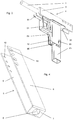
- a closure 4 which is designed as a ground closure, consists essentially of a U-shaped bent bracket 5 with two legs 6 and a base connecting them 7. In the base 7 there is an opening 8, through which the barrel 1 is guided. At the free ends of the legs 6, a closure piece 9 is attached.
- the closure piece 9 is preferably bolted to the legs 6, but may be attached thereto in other ways, e.g. riveted or welded.
- sink holes 10 and 9 threaded holes 11 are mounted in the closure piece, in which countersunk screws can be screwed through the countersunk holes 10.
- the bracket 5 can be easily stamped and bent from a sheet.
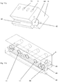
- the barrel holder 3 ( Fig. 7a and 7b ) consists in the illustrated embodiment of a square tube, the opposite walls 12, 13 have bores 31 a, 31 b, in which the cartridge bearing end 2 of the barrel 1 can be accommodated.
- a locking part 16 ( Fig. 9 ) consists of a cuboid block 17 which is inserted into the front end 15 of the barrel holder 3. On its underside 18, it has a recess 19 whose curvature corresponds to the outer diameter of the cartridge bearing end 2 of the barrel 1.
- the depth of the recess 19 on the locking part 16 corresponds approximately to the depth of the recess 14 on the barrel 1 and the remaining length L1 on the underside 18 of the locking member 16 is substantially equal to the length L2 of the recess on the barrel 1, so that the locking member 16 with engage the projection 20 thus formed in the recess 14 on the barrel 1 and this fixed both axially and in the circumferential direction.
- a bore 21 is mounted in this and in the walls 12, 13 of the barrel holder 1 holes 22 are also provided, through which a locking pin can be inserted.
- the locking pin can in turn be e.g. secured by worm screws in holes 23 on the locking member 16.
- the weapon according to the invention has a magazine shaft 24 ( Fig. 6a and 6b ), in which a per se known rod magazine 25 is detachably received in a known per se.
- the magazine shaft 24, which can form a handle at the same time, but can also be surrounded by an envelope, for example made of wood or plastic, to increase the comfort when carrying, holding and shooting, can also be easily punched out of a sheet and bent and has a U-shape with two side walls 26, 27 and a rear wall 28.
- the fourth wall is replaced by a U-shaped wall element 86 (shown in FIG. 2) inserted between the side walls 26, 27. Fig. 10 ), whose side walls 79, 80 connected to the side walls 26, 27, for example, spot-welded, are.
- a carrier plate 32 (FIG. Fig. 8 ), which is preferably also punched from a sheet, has a U-shape with two legs 33, 34, with which it is attached to the tabs 29, 30 of the magazine shaft 24, for example, welded, is.
- At the base 35 of the support plate 32 are two holes 36, 37, through which a guide 38 for the closure piece 9 can be screwed to the support plate 32.
- the guide 38 ( Fig. 12a and 12b ) is in the illustrated embodiment, a solid, block-shaped block with two threaded holes 39, 40 which correspond in position to the bores 36, 37 on the support plate.
- On the support plate 38 opposite upper side, it has a guide groove 41, in which a web 42 on the underside of the closure piece 9 is displaceable.
- a recessed bottom 43 and a fixed, optionally exchangeable, striker 44 (FIG. Figs. 17a and 17b ) arranged.
- the firing pin 44 may be exchangeable, for which example two reserve receptacles 85 may be provided in the closure piece 9.
- the legs 6 of the U-shaped bracket 5 are slidably guided in each case on a guide 45 on opposite sides of the barrel holder in the longitudinal direction, which have a substantially U-shape.
- the base of the U-shape is in each case formed by one of the opposing walls 46, 47 of the barrel holder 3.
- the side walls of the U-shaped guides are formed by upper and lower protrusions.
- the upper projections 48, 49 are formed by a projecting edge on the locking part 16 and the lower projections of the legs 33, 34 of the support plate 32nd
- the carriage consisting of the U-shaped bracket 5 and the closure piece 9 is thus performed in triplicate, namely through the opening 8 on the bracket 5, the legs 6 on the barrel holder 3 and the web 42 on the guide member 38.
- the carriage is by a compression spring 50th pressed forward, between the barrel holder 3 and the base 7 of the bracket. 8 is clamped and surrounds the barrel 1.
- the rear position of the carriage of a in Fig. 13 Fang claw 51 shown held which preferably consists of a stamped, U-shaped bent sheet metal part and two legs 52, 53 and a base 54 is made.
- latching hooks 54, 55 are arranged, which engage the base 7 of the U-shaped bracket 5.
- the free ends of the legs 52, 53 may be interconnected for reasons of stability.
- the catch claw 51 is pivotable about an axis 58, which are defined by holes 59, 60 in the legs 52, 53.
- a likewise preferred from a punched, U-shaped bent sheet metal part existing trigger 61 ( Figs. 14a and 14b ) has in two legs 62, 63 bores 64, 65, which also define a pivot axis which coincides in the assembled state with the axis 58 of the catch claw and is formed by a common bolt.
- the trigger 61 is slightly narrower than the catch claw 51 and between the legs 52, 53 added.
- the two legs 62, 63 of the trigger 61 have contact surfaces 66, 67, with which they rest against a lower edge 68 of the base 54 of the catch claw 51 when the trigger 61 is pressed, whereby the catch claw 51 in Fig. 1 pivoted counterclockwise and the carriage 4 is released so that it is accelerated by the force of the spring 50 is moved forward to the barrel 1 out.
- a securing bracket 69 is provided, which also preferably consists of a stamped, U-shaped sheet metal part, and is mounted pivotably about an axis 70. Its legs 71, 72 have hooks 73, 74 which engage the upper edge 75 of the base 54 of the catch claw 51 when the securing bracket 69 is in its normal position, in which it is pressed clockwise by a spring, not shown.
- the handle portion 76 of the securing bracket 69 is within the trigger 61 and in its extension and is supported laterally with projections 56, 57 on the side walls 46, 47 of the barrel holder 3 from. Since the securing bow 69 blocks the catching claw 51 when it is not pressed, the catching claw 51 and thus also the carriage are secured, the trigger should be pressed unintentionally or the weapon is subjected to such a strong impact that the catching claw 51 unlocks. However, if the safety bar 69 is pressed simultaneously, it can be assumed that the shooter holds the weapon sufficiently firmly in his hand and intentionally wants to give a shot.
- the locking lever 81 is also preferably made of a stamped, U-shaped bent sheet metal part and has a base 82 a bent nose 83 and side walls 83, 84, the corners 87, 88 engage in a recess in a wall of the magazine 25.
Landscapes
- Engineering & Computer Science (AREA)
- General Engineering & Computer Science (AREA)
- Portable Nailing Machines And Staplers (AREA)
- Toys (AREA)
- Closures For Containers (AREA)
- Operating, Guiding And Securing Of Roll- Type Closing Members (AREA)
- Telephone Set Structure (AREA)
- Aiming, Guidance, Guns With A Light Source, Armor, Camouflage, And Targets (AREA)
Description
- Die Erfindung betrifft eine vollautomatische Handfeuerwaffe mit den Merkmalen des Oberbegriffs des Anspruchs 1.
- Aus der
EP 0 159 441 A2 ist eine Handfeuerwaffe mit einem Schlitten bekannt, der einerseits an einer Führung an einer Laufhalterung, an welcher der Lauf lösbar befestigt ist, und andererseits über eine mit dem Schlitten verbundene Hülse am Lauf verschiebbar gelagert ist. - Die erfindungsgemäße Waffe ist nach dem bekannten Prinzip eines offen zuschießenden Masseverschlusses aufgebaut. Bei einer schussbereiten Waffe befindet sich keine Patrone im Patronenlager und der Verschluss wird in einer hinteren Position festgehalten. Durch Betätigen des Abzugs wird der Verschluss freigegeben und durch eine Feder nach vorn zum Lauf hin bewegt. Dabei nimmt er eine Patrone aus dem Magazin mit, schiebt sie in das Patronenlager und zündet sie durch den Aufprall des Schlagbolzens am Zündhütchen der Patrone. Die Massenträgheit bewirkt, dass der Verschluss die Patronenhülse im Patronenlager im Wesentlichen solange festhält, bis das Geschoss den Lauf verlassen hat. Die Patronenhülse und der Verschluss werden dann durch den Gasdruck so weit nach hinten bewegt, bis der Verschluss bei losgelassenem Abzug wieder gefangen wird. Auf dem Rückweg wird die Patronenhülse ausgeworfen. Wenn der Abzug gedrückt bleibt, wiederholt sich dieser Vorgang, solange Munition vorhanden ist.
- Aufgabe der Erfindung ist es, eine derartige Waffe zu schaffen, die möglichst einfach und günstig hergestellt werden kann.
- Gelöst wird diese Aufgabe mit einer Handfeuerwaffe mit den Merkmalen des Anspruchs 1.
- Bevorzugte Ausführungsformen der Erfindung sind Gegenstand der Unteransprüche.
- Weitere Merkmale und Vorteile der Erfindung ergeben sich aus der nachfolgenden Beschreibung eines bevorzugten Ausführungsbeispiels der Erfindung unter Bezugnahme auf die angeschlossenen Zeichnungen. Es zeigt (nicht maßstabsgetreu):
-
Fig. 1 eine Seitenansicht einer bevorzugten Ausführungsform einer erfindungsgemäßen Handfeuerwaffe, -
Fig. 2 die Handfeuerwaffe in Schrägansicht, -
Fig. 3 die Handfeuerwaffe in Schrägansicht aus einer anderen Perspektive, -
Fig. 4 einen U-förmigen Bügel der Handfeuerwaffe, -
Fig. 5 einen Lauf der Handfeuerwaffe, -
Fig. 6a und 6b einen Magazinschacht der Handfeuerwaffe, -
Fig. 7a und 7b eine Laufhalterung der Handfeuerwaffe, -
Fig. 8 eine Trägerplatte der Handfeuerwaffe, -
Fig. 9 einen Verriegelungsteil der Handfeuerwaffe, -
Fig. 10 ein Wandelement des Magazinschachtes der Handfeuerwaffe, -
Fig. 11a und 11b ein Verschlussstück der Handfeuerwaffe, -
Fig. 12a und 12b eine Führung der Handfeuerwaffe, -
Fig. 13 eine Fangkralle der Handfeuerwaffe, -
Fig. 14a und 14b einen Abzug der Handfeuerwaffe, -
Fig. 15 einen Sicherungsbügel der Handfeuerwaffe, -
Fig. 16 einen Verriegelungshebel der Handfeuerwaffe und -
Fig. 17a und 17b einen Schlagbolzen der Handfeuerwaffe. - Die in den Zeichnungen dargestellte bevorzugte Ausführungsform der erfindungsgemäß Handfeuerwaffe weist einen Lauf 1 auf, dessen patronenlagerseitiges Ende 2 an einer Laufhalterung 3 befestigt ist. Ein Verschluss 4, der als Masseverschluss ausgeführt ist, besteht im Wesentlichen aus einem U-förmig gebogenen Bügel 5 mit zwei Schenkeln 6 und einer diese verbindenden Basis 7. In der Basis 7 befindet sich eine Öffnung 8, durch die der Lauf 1 geführt ist. An den freien Enden der Schenkel 6 ist ein Verschlussstück 9 befestigt. Das Verschlussstück 9 ist bevorzugt mit den Schenkeln 6 verschraubt, kann aber auch auf andere Weise daran befestigt sein, z.B. angenietet oder angeschweißt sein. Zum Verschrauben sind in den Enden der Schenkel Senklöcher 10 und im Verschlussstück 9 Gewindebohrungen 11 angebracht, in welche Senkkopfschrauben durch die Senklöcher 10 eingeschraubt werden können. Der Bügel 5 kann auf einfache Weise aus einem Blech gestanzt und gebogen werden.
- Die Laufhalterung 3 (
Fig. 7a und 7b ) besteht in der dargestellten Ausführungsform aus einem Vierkantrohr, dessen gegenüberliegende Wände 12, 13 Bohrungen 31a, 31b aufweisen, in denen das patronenlagerseitige Ende 2 des Laufes 1 aufgenommen werden kann. Am Lauf 1 (Fig. 5 ) ist am patronenlagerseitigen Ende 2 eine Vertiefung 14 angebracht, die in der eingebauten Stellung des Laufes 1 zum stirnseitigen, oberen Ende 15 der Laufhalterung 3 weist und im Inneren der Laufhalterung 3 angeordnet ist. - Ein Verriegelungsteil 16 (
Fig. 9 ) besteht aus einem quaderförmigen Block 17, der in das stirnseitige Ende 15 der Laufhalterung 3 gesteckt wird. An seiner Unterseite 18 weist er eine Ausnehmung 19 auf, deren Krümmung dem Außendurchmesser des patronenlagerseitigen Endes 2 des Laufes 1 entspricht. Die Tiefe der Ausnehmung 19 am Verriegelungsteil 16 entspricht etwa der Tiefe der Ausnehmung 14 am Lauf 1 und die verbleibende Länge L1 an der Unterseite 18 des Verriegelungsteils 16 ist im Wesentlichen gleich lang wie die Länge L2 der Ausnehmung am Lauf 1, sodass der Verriegelungsteil 16 mit dem so gebildeten Vorsprung 20 in die Ausnehmung 14 am Lauf 1 eingreifen und diesen sowohl axial als auch in Umfangsrichtung fixiert. - Zum Befestigen des Verriegelungsteils 16 ist in diesem eine Bohrung 21 angebracht und in den Wänden 12, 13 der Laufhalterung 1 sind ebenfalls Bohrungen 22 angebracht, durch welche ein Verriegelungsstift gesteckt werden kann. Der Verriegelungsstift kann seinerseits z.B. durch Wurmschrauben in Bohrungen 23 am Verriegelungsteil 16 gesichert werden.
- Die erfindungsgemäße Waffe weist einen Magazinschacht 24 auf (
Fig. 6a und 6b ), in dem ein an sich bekanntes Stangenmagazin 25 auf an sich bekannte Weise lösbar aufgenommen wird. Der Magazinschacht 24, der gleichzeitig einen Griff bilden kann, aber auch mit einer Umhüllung z.B. aus Holz oder Kunststoff umgeben sein kann, um den Komfort beim Tragen, Halten und Schießen zu erhöhen, kann ebenfalls auf einfache Weise aus einem Blech ausgestanzt und gebogen werden und weist eine U-Form mit zwei Seitenwänden 26, 27 und einer Rückwand 28 auf. Die vierte Wand wird durch ein zwischen die Seitenwände 26, 27 eingesetztes, U-förmiges Wandelement 86 (Fig. 10 ) gebildet, dessen Seitenwände 79, 80 mit den Seitenwänden 26, 27 verbunden, z.B. punktverschweißt, werden. - An den Seitenwänden 26, 27 des Magazinschachtes 24 befinden sich an deren oberen Enden zwei im rechten Winkel nach außen gebogene Laschen 29, 30. In einer Wand 26 ist eine Ausnehmung 56 mit zwei nach außen gebogenen Laschen 57 für die Lagerung eines Verriegelungshebels 81 (
Fig. 16 ) angebracht. - Eine Trägerplatte 32 (
Fig. 8 ), die bevorzugt ebenfalls aus einem Blech gestanzt ist, weist eine U-Form mit zwei Schenkeln 33, 34 auf, mit denen sie an den Laschen 29, 30 des Magazinschachtes 24 befestigt, z.B. angeschweißt, ist. An der Basis 35 der Trägerplatte 32 befinden sich zwei Bohrungen 36, 37, durch welche eine Führung 38 für das Verschlussstück 9 an der Trägerplatte 32 angeschraubt werden kann. Die Führung 38 (Fig. 12a und 12b ) ist in der dargestellten Ausführungsform ein massiver, quaderförmiger Block mit zwei Gewindebohrungen 39, 40, die in ihrer Lage den Bohrungen 36, 37 an der Trägerplatte entsprechen. Auf der der Trägerplatte 38 gegenüber liegenden Oberseite weist er eine Führungsnut 41 auf, in welcher ein Steg 42 an der Unterseite des Verschlussstücks 9 verschiebbar ist. - Am Verschlussstück 9 sind des Weiteren noch ein vertiefter Stoßboden 43 und ein fester, gegebenenfalls austauschbarer, Schlagbolzen 44 (
Fig. 17a und 17b ) angeordnet. Der Schlagbolzen 44 kann austauschbar sein, wofür z.B. zwei Reserveaufnahmen 85 im Verschlussstück 9 vorgesehen sein können. - Die Schenkel 6 des U-förmigen Bügels 5 sind an jeweils einer Führung 45 auf gegenüber liegenden Seiten der Laufhalterung in Längsrichtung verschiebbar geführt, die im Wesentlichen eine U-Form aufweisen. Die Basis der U-Form wird jeweils von einer der einander gegenüber liegenden Wänden 46, 47 der Laufhalterung 3 gebildet. Die Seitenwände der U-förmigen Führungen werden von oberen und unteren Vorsprüngen gebildet. Die oberen Vorsprünge 48, 49 werden von einem vorspringenden Rand am Verriegelungsteil 16 gebildet und die unteren Vorsprünge von den Schenkeln 33, 34 der Trägerplatte 32.
- Der Schlitten bestehend aus dem U-förmigen Bügel 5 und dem Verschlussstück 9 ist somit dreifach geführt, nämlich durch die Öffnung 8 am Bügel 5, die Schenkel 6 an der Laufhalterung 3 und den Steg 42 am Führungsteil 38. Der Schlitten wird durch eine Druckfeder 50 nach vorne gedrückt, die zwischen der Laufhalterung 3 und der Basis 7 des Bügels 8 eingespannt ist und den Lauf 1 umgibt.
- In seiner in
Fig. 1 bis 3 dargestellten, hinteren Stellung wird der Schlitten von einer inFig. 13 dargestellten Fangkralle 51 gehalten, die bevorzugt aus einem gestanzten, U-förmig gebogenen Blechteil besteht und zwei Schenkel 52, 53 und einer Basis 54 besteht. An den Enden der Schenkel 52, 53 der Fangkralle 51 sind Rasthaken 54, 55 angeordnet, die an der Basis 7 des U-förmigen Bügels 5 angreifen. Die freien Enden der Schenkel 52, 53 können aus Stabilitätsgründen miteinander verbunden sein. Die Fangkralle 51 ist um eine Achse 58 verschwenkbar, welche durch Bohrungen 59, 60 in den Schenkeln 52, 53 definiert werden. - Ein ebenfalls bevorzugt aus einem gestanzten, U-förmig gebogenen Blechteil bestehender Abzug 61 (
Fig. 14a und 14b ) weist in zwei Schenkeln 62, 63 Bohrungen 64, 65 auf, welche ebenfalls eine Schwenkachse definieren, die im zusammengebauten Zustand mit der Achse 58 der Fangkralle zusammen fällt und durch einen gemeinsamen Bolzen gebildet wird. Der Abzug 61 ist etwas schmäler als die Fangkralle 51 und zwischen deren Schenkeln 52, 53 aufgenommen. - Die beiden Schenkel 62, 63 des Abzugs 61 weisen Anlageflächen 66, 67 auf, mit denen sie an einer Unterkante 68 der Basis 54 der Fangkralle 51 anliegen, wenn der Abzug 61 gedrückt wird, womit die Fangkralle 51 in
Fig. 1 gegen den Uhrzeigersinn verschwenkt und der Schlitten 4 freigegeben wird, sodass dieser durch die Kraft der Feder 50 beschleunigt nach vorne zum Lauf 1 hin bewegt wird. - Auf diesem Weg wird durch den Steg 42 eine Patrone aus dem Magazin 25 geschoben und in das Patronenlager eingeführt. Sobald sich das Verschlussstück 9 ganz vorne befindet, wird die Patrone durch den Schlagbolzen 44 gezündet, worauf der Schlitten durch die Patrone unter der Wirkung des Gasdruckes wieder zurück bewegt wird. Die Fangkralle 51 wird durch eine nicht dargestellte Feder im Uhrzeigersinn belastet und bewegt sich in diese Richtung, sobald der Abzug 61 losgelassen wird. Auf dem Rückweg des Schlittens stößt die Patrone gegen die Führung 38 und wird dadurch nach oben ausgeworfen.
- Um ein unbeabsichtigtes Auslösen eines Schusses zu verhindern, ist ein Sicherungsbügel 69 vorgesehen, der ebenfalls bevorzugt aus einem gestanzten, U-förmig gebogenen Blechteil besteht, und um eine Achse 70 verschwenkbar gelagert ist. Seine Schenkel 71, 72 weisen Haken 73, 74 auf, die an der Oberkante 75 der Basis 54 der Fangkralle 51 angreifen, wenn sich der Sicherungsbügel 69 in seiner Grundstellung befindet, in die er im Uhrzeigersinn von einer nicht dargestellten Feder gedrückt wird.
- Der Griffteil 76 des Sicherungsbügels 69 liegt innerhalb des Abzugs 61 und in dessen Verlängerung und stützt sich seitlich mit Vorsprüngen 56, 57 an den Seitenwänden 46, 47 der Laufhalterung 3 ab. Da der Sicherungsbügel 69 die Fangkralle 51 blockiert, wenn er nicht gedrückt wird, sind die Fangkralle 51 und somit auch der Schlitten gesichert, sollte unbeabsichtigt der Abzug gedrückt werden oder die Waffe einem so starken Stoß ausgesetzt werden, dass die Fangkralle 51 entriegelt. Wenn jedoch der Sicherungsbügel 69 gleichzeitig gedrückt wird, kann davon ausgegangen werden, dass der Schütze die Waffe ausreichend fest in der Hand hält und mit Absicht einen Schuss abgeben will.
- Bei der Laufhalterung 3 (
Fig. 7a und 7b ) ist auf etwa 2/3 der Länge die eine Wand 13 des Profilrohres entfernt und in den beiden angrenzenden Wänden 46, 47 sind paarweise Bohrungen 77, 78 angebracht, in welche die Bolzen der Achsen 58 und 70 der Fangkralle 51 und des Abzugs 61 bzw. des Sicherungsbügels 69 gesteckt sind. Auf diese Weise kann eine Abzugsgruppe gebildet werden, die einfach zu montieren und demontieren ist. - Der Verriegelungshebel 81 gemäß
Fig. 16 ist ebenfalls bevorzugt aus einem gestanzten, U-förmig gebogenen Blechteil hergestellt und weist eine Basis 82 eine umgebogene Nase 83 und Seitenwände 83, 84 auf, deren Ecken 87, 88 in eine Ausnehmung in einer Wand des Magazins 25 eingreifen.
Claims (17)
- Vollautomatische Handfeuerwaffe mit einem Lauf (1) und einem zuschießenden Masseverschluss, der einen Schlitten mit einem Verschlussstück (9) aufweist, wobei der Schlitten an einer Führung (45) verschiebbar gelagert ist, und wobei die Führung (45) an einer Laufhalterung (3) angeordnet ist, an welcher der Lauf (1) lösbar befestigt ist, dadurch gekennzeichnet, dass der Schlitten einen im Wesentlichen U-förmigen Bügel (5) mit zwei Schenkeln (6) und einer Basis (7) aufweist, an dem das Verschlussstück (9) angeordnet ist, dass der Lauf (1) durch eine Öffnung (8) in der Basis (7) des U-förmigen Bügels (5) ragt und der Schlitten an der Öffnung (8) am Lauf (1) verschiebbar gelagert ist, und dass die Führung (45) durch zwei einander gegenüber liegende U-förmige Vertiefungen an der Laufhalterung (3) gebildet wird, in welchen die Schenkel (6) des U-förmigen Bügels (5) geführt sind.
- Handfeuerwaffe nach Anspruch 1, dadurch gekennzeichnet, dass zwischen dem Bügel (5) und der Führung (45) eine den Lauf (1) umgebende Druckfeder (50) eingespannt ist.
- Handfeuerwaffe nach Anspruch 1 oder 2, dadurch gekennzeichnet, dass der Bügel (5) aus einem abgekanteten Blech hergestellt ist.
- Handfeuerwaffe nach einem der Ansprüche 1 bis 3, dadurch gekennzeichnet, dass die Führung (45) an einer Abzugsgruppe angeordnet ist.
- Handfeuerwaffe nach Anspruch 1 bis 4, dadurch gekennzeichnet, dass das Verschlussstück (9) im Bereich der freien Enden von Schenkeln (6) des Bügels (5) zwischen diesen aufgenommen und mit diesen fest verbunden, insbesondere verschraubt oder vernietet, ist.
- Handfeuerwaffe nach einem der Ansprüche 1 bis 5, dadurch gekennzeichnet, dass die Laufhalterung (3) im Führungsbereich im Wesentlichen quaderförmig ist und zur Begrenzung der U-förmigen Vertiefungen Vorsprünge (48, 49) daran angeordnet, insbesondere befestigt, sind.
- Handfeuerwaffe nach Anspruch 6, dadurch gekennzeichnet, dass ein Paar von Vorsprüngen (48, 49) an einem Verriegelungsteil (16) angeordnet ist, das am stirnseitigen Ende (15) der Laufhalterung (3) befestigt ist und dass der Verriegelungsteil (16) in eine Vertiefung (14) am Lauf (1) eingreift.
- Handfeuerwaffe nach einem der Ansprüche 1 bis 7, dadurch gekennzeichnet, dass an einem Magazinschacht (24) eine Trägerplatte (32) angeordnet ist, an der eine zweite Führung (38) für den Schlitten, insbesondere das daran angeordnete Verschlussstück (9), befestigt ist.
- Handfeuerwaffe nach einem der Ansprüche 6 bis 8, dadurch gekennzeichnet, dass ein zweites Paar von Vorsprüngen (33, 34) an der Trägerplatte (32) angeordnet ist.
- Handfeuerwaffe nach einem der Ansprüche 1 und 8, dadurch gekennzeichnet, dass die Laufhalterung (3) am Magazinschacht (24) befestigt ist.
- Handfeuerwaffe nach einem der Ansprüche 1 bis 10, dadurch gekennzeichnet, dass die Laufhalterung (3) aus einem rechteckigen Profilrohr mit zwei Öffnungen in gegenüberliegenden Wänden (12, 13) besteht, durch welche der Lauf (1) quer zur Längsrichtung des Profilrohres ragt.
- Handfeuerwaffe nach Anspruch 7 und 11, dadurch gekennzeichnet, dass der Verriegelungsteil (16) in das stirnseitigen Ende (15) des Profilrohres gesteckt und dort befestigt ist.
- Handfeuerwaffe nach einem der Ansprüche 1 bis 12, dadurch gekennzeichnet, dass am Schlitten wenigstens eine Rast, insbesondere ein Rastvorsprung (56, 57), und am Magazinschacht (24) eine verschwenkbar gelagerte Fangkralle (51) angeordnet sind.
- Handfeuerwaffe nach Anspruch 13, dadurch gekennzeichnet, dass die Fangkralle (51) ein im Wesentlichen U-förmig gebogener Bügel mit zwei Schenkeln (52, 53) ist, an deren Enden Rasthaken (54, 55) angeordnet sind, und dass ein Abzug (61), der an der selben Achse (58) wie die Fangkralle (51) gelagert ist, an einer die beiden Schenkel (52, 53) verbindenden Basis (54) angreift.
- Handfeuerwaffe nach Anspruch 14, dadurch gekennzeichnet, dass ein schwenkbar gelagerter Sicherungsbügel (69) an der dem Abzug (61) gegenüber liegenden Seite an der Basis (54) angreift und dass ein Griffteil (76) des Sicherungsbügels in Verlängerung des Abzug (61) liegt.
- Handfeuerwaffe nach einem der Ansprüche 4 bis 15, dadurch gekennzeichnet, dass an der Laufhalterung (3) die Fangkralle (51), der Abzug (61) und der Sicherungsbügel (69) gelagert sind.
- Handfeuerwaffe nach Anspruch 16, dadurch gekennzeichnet, dass die Abzugsgruppe, insbesondere die Laufhalterung (3), am Magazinschacht (24) befestigt ist.
Priority Applications (2)
| Application Number | Priority Date | Filing Date | Title |
|---|---|---|---|
| PL15450024T PL2960615T3 (pl) | 2014-06-26 | 2015-06-18 | Pistolet |
| RS20180357A RS57050B1 (sr) | 2014-06-26 | 2015-06-18 | Ručno vatreno oružje |
Applications Claiming Priority (1)
| Application Number | Priority Date | Filing Date | Title |
|---|---|---|---|
| ATA507/2014A AT515524B1 (de) | 2014-06-26 | 2014-06-26 | Handfeuerwaffe |
Publications (2)
| Publication Number | Publication Date |
|---|---|
| EP2960615A1 EP2960615A1 (de) | 2015-12-30 |
| EP2960615B1 true EP2960615B1 (de) | 2017-12-27 |
Family
ID=53488281
Family Applications (1)
| Application Number | Title | Priority Date | Filing Date |
|---|---|---|---|
| EP15450024.3A Active EP2960615B1 (de) | 2014-06-26 | 2015-06-18 | Handfeuerwaffe |
Country Status (12)
| Country | Link |
|---|---|
| US (1) | US9714801B2 (de) |
| EP (1) | EP2960615B1 (de) |
| AR (1) | AR100993A1 (de) |
| AT (1) | AT515524B1 (de) |
| AU (1) | AU2015203578B2 (de) |
| BR (1) | BR102015015214B1 (de) |
| CA (1) | CA2895661C (de) |
| IL (1) | IL239611B (de) |
| MA (1) | MA39267A (de) |
| PL (1) | PL2960615T3 (de) |
| RS (1) | RS57050B1 (de) |
| RU (1) | RU2671433C2 (de) |
Family Cites Families (30)
| Publication number | Priority date | Publication date | Assignee | Title |
|---|---|---|---|---|
| US1377629A (en) * | 1920-01-26 | 1921-05-10 | Waldo E Rosebush | Composite automatic firearm |
| US1516540A (en) * | 1922-12-20 | 1924-11-25 | Mann Willy | Automatic pistol |
| US1840054A (en) * | 1928-11-23 | 1932-01-05 | Alva C Washburne | Firearm |
| US1911494A (en) * | 1932-12-12 | 1933-05-30 | William C Floyd | Automatic pistol |
| US2377703A (en) * | 1943-04-28 | 1945-06-05 | Remington Arms Co Inc | Firearm |
| US2529359A (en) * | 1946-09-28 | 1950-11-07 | Harry A Stevens | Safety device for automatic pistols |
| US2655839A (en) * | 1946-11-05 | 1953-10-20 | Sturm Ruger & Co | Blowback autoloading pistol |
| US2765710A (en) * | 1952-12-27 | 1956-10-09 | Earl H Bradley | Breech block controlling mechanism for a retarded blow back gun |
| US2744448A (en) * | 1953-11-30 | 1956-05-08 | Edward A Allen | Automatic pistol |
| DE1040420B (de) * | 1956-09-11 | 1958-10-02 | Sportarms Mfg And Dev Corp | Rueckstossbetaetigte Selbstladefeuerwaffe |
| US3167876A (en) * | 1960-10-19 | 1965-02-02 | Jr John M Milroy | Handgun |
| US3306168A (en) * | 1965-08-16 | 1967-02-28 | Howard J Blumrick | Gas operated semi-automatic pistol |
| DE1728251C3 (de) * | 1968-09-18 | 1975-10-02 | Heckler & Koch Gmbh | Griffstück für eine Selbstladepistole |
| IT1037712B (it) * | 1975-04-29 | 1979-11-20 | Ghisoni E | Pistola automatica con chiusura a massa |
| US4061075A (en) * | 1976-10-07 | 1977-12-06 | Smith Frank P | Automatic weapon |
| US4127056A (en) * | 1977-06-30 | 1978-11-28 | Kart Sporting Arms Corporation | Automatic pistol barrel locking device and sub-caliber conversion therefor |
| DE3142350A1 (de) * | 1981-10-26 | 1983-05-05 | Rudolf 7858 Weil Paciner | "schusswaffe" |
| US4602450A (en) * | 1983-07-13 | 1986-07-29 | Pachmayr Gun Works, Inc. | Forend structure for pistol conversion assembly |
| US4579037A (en) | 1984-02-13 | 1986-04-01 | Weapon Technology Systems R & D, Ltd. | Machine pistol with retarded blowback |
| US4567810A (en) * | 1984-03-13 | 1986-02-04 | Wildfire Munitions, Inc. | Automatic firearm |
| US5123329A (en) * | 1989-12-15 | 1992-06-23 | Irwin Robert M | Self-actuating blow forward firearm |
| US5736667A (en) * | 1996-05-06 | 1998-04-07 | Munostes; Luis Eduardo Hernandez | Automatic firearm arranged for high safety and rapid dismantling |
| US6079138A (en) * | 1997-06-10 | 2000-06-27 | Meaker; Donald L. | Folded delay blowback operating system for automatic hand held firing weaponry |
| RU2126521C1 (ru) * | 1997-12-18 | 1999-02-20 | Центральный научно-исследовательский институт точного машиностроения | Самозарядный пистолет |
| US20040007124A1 (en) * | 2002-07-12 | 2004-01-15 | Sheriff Company, Ltd. | Micro-roller sliding system for guiding movable gun parts involved in projectile discharge |
| DE102004021952B3 (de) * | 2004-05-04 | 2005-12-29 | Heckler & Koch Gmbh | Selbstlade-Handfeuerwaffe mit beschleunigtem Verschlußträger |
| US7225574B2 (en) * | 2004-09-09 | 2007-06-05 | Battelle Energy Alliance, Llc | Forwardly movable assembly for a firearm |
| PL372686A1 (pl) * | 2005-02-09 | 2006-08-21 | Piotr Grabowski | Mechanizm reakcyjny do broni palnej |
| US8528243B1 (en) * | 2012-07-10 | 2013-09-10 | Gaston Glock | Pistols and methods of manufacture |
| US20140026745A1 (en) * | 2012-07-26 | 2014-01-30 | Shanyao Lee | Glock Buffer |
-
2014
- 2014-06-26 AT ATA507/2014A patent/AT515524B1/de active
-
2015
- 2015-06-17 MA MA039267A patent/MA39267A/fr unknown
- 2015-06-18 RS RS20180357A patent/RS57050B1/sr unknown
- 2015-06-18 PL PL15450024T patent/PL2960615T3/pl unknown
- 2015-06-18 EP EP15450024.3A patent/EP2960615B1/de active Active
- 2015-06-24 BR BR102015015214-0A patent/BR102015015214B1/pt active IP Right Grant
- 2015-06-24 IL IL239611A patent/IL239611B/en active IP Right Grant
- 2015-06-25 RU RU2015125248A patent/RU2671433C2/ru active
- 2015-06-25 CA CA2895661A patent/CA2895661C/en active Active
- 2015-06-25 AR ARP150102037A patent/AR100993A1/es active IP Right Grant
- 2015-06-26 AU AU2015203578A patent/AU2015203578B2/en active Active
- 2015-06-26 US US14/751,322 patent/US9714801B2/en active Active
Non-Patent Citations (1)
| Title |
|---|
| None * |
Also Published As
| Publication number | Publication date |
|---|---|
| AT515524A4 (de) | 2015-10-15 |
| PL2960615T3 (pl) | 2018-06-29 |
| RU2015125248A3 (de) | 2018-08-30 |
| AR100993A1 (es) | 2016-11-16 |
| RU2015125248A (ru) | 2017-01-10 |
| BR102015015214A2 (pt) | 2016-06-14 |
| AU2015203578A1 (en) | 2016-01-21 |
| RU2671433C2 (ru) | 2018-10-31 |
| CA2895661A1 (en) | 2015-12-26 |
| CA2895661C (en) | 2022-02-22 |
| AT515524B1 (de) | 2015-10-15 |
| MA39267A (fr) | 2017-12-26 |
| US9714801B2 (en) | 2017-07-25 |
| US20160061544A1 (en) | 2016-03-03 |
| RS57050B1 (sr) | 2018-05-31 |
| BR102015015214B1 (pt) | 2022-02-22 |
| AU2015203578B2 (en) | 2020-01-16 |
| IL239611B (en) | 2018-11-29 |
| BR102015015214A8 (pt) | 2021-09-08 |
| EP2960615A1 (de) | 2015-12-30 |
Similar Documents
| Publication | Publication Date | Title |
|---|---|---|
| EP3011253B1 (de) | Umrüstbausatz für eine schusswaffe sowie verfahren zum umrüsten einer schusswaffe | |
| EP1830152B1 (de) | Steckmagazin einer Handfeuerwaffe | |
| EP1257775B1 (de) | Mehrlade-handfeuerwaffe mit lösbarer verschlusssperre | |
| WO2007090611A1 (de) | Handfeuerwaffe mit durchladehebel | |
| DE102004021952B3 (de) | Selbstlade-Handfeuerwaffe mit beschleunigtem Verschlußträger | |
| DE3202806C2 (de) | Granatwerfer-Zusatzwaffe zum Anbau an Schnellfeuergewehre | |
| DE102017128911B4 (de) | Selbstladepistole | |
| WO2023104548A1 (de) | Gewehre mit einer verschlussfangvorrichtung | |
| DE3120024A1 (de) | Selbsttaetige sicherungsvorrichtung fuer handfeuerwaffen | |
| EP4038333B1 (de) | Karabiner mit spannschieber | |
| EP1626243B1 (de) | Handfeuerwaffe für sportliches Schiessen | |
| AT519342A1 (de) | Patronenhülsen-Vorwärtsauswurfsystem | |
| EP2960615A1 (de) | Handfeuerwaffe | |
| DE10008979B4 (de) | Mehrlade-Handfeuerwaffe mit lösbarer Verschlußsperre | |
| DE10051708B4 (de) | Selbstladepistole | |
| DE90430C (de) | ||
| DE518372C (de) | Selbstladepistole | |
| WO2001022023A1 (de) | Gewehr mit einem gelenkmechanismus zwischen dem schaft und dem waffengehäuse | |
| AT503304B1 (de) | Pistole | |
| DE102006005429B4 (de) | Verschluss-Einrast-Vorrichtung | |
| AT45225B (de) | Selbstladegewehr. | |
| DE294194C (de) | ||
| DE336272C (de) | Sicherungseinrichtung fuer Selbstladefeuerwaffen | |
| AT520640A4 (de) | Schusswaffe | |
| WO2010078978A1 (de) | Druckluftpistole |
Legal Events
| Date | Code | Title | Description |
|---|---|---|---|
| PUAI | Public reference made under article 153(3) epc to a published international application that has entered the european phase |
Free format text: ORIGINAL CODE: 0009012 |
|
| AK | Designated contracting states |
Kind code of ref document: A1 Designated state(s): AL AT BE BG CH CY CZ DE DK EE ES FI FR GB GR HR HU IE IS IT LI LT LU LV MC MK MT NL NO PL PT RO RS SE SI SK SM TR |
|
| AX | Request for extension of the european patent |
Extension state: BA ME |
|
| 17P | Request for examination filed |
Effective date: 20160628 |
|
| RAV | Requested validation state of the european patent: fee paid |
Extension state: MA Effective date: 20160628 |
|
| RAX | Requested extension states of the european patent have changed |
Extension state: ME Payment date: 20160628 Extension state: BA Payment date: 20160628 |
|
| RBV | Designated contracting states (corrected) |
Designated state(s): AL AT BE BG CH CY CZ DE DK EE ES FI FR GB GR HR HU IE IS IT LI LT LU LV MC MK MT NL NO PL PT RO RS SE SI SK SM TR |
|
| GRAP | Despatch of communication of intention to grant a patent |
Free format text: ORIGINAL CODE: EPIDOSNIGR1 |
|
| INTG | Intention to grant announced |
Effective date: 20170714 |
|
| GRAS | Grant fee paid |
Free format text: ORIGINAL CODE: EPIDOSNIGR3 |
|
| GRAA | (expected) grant |
Free format text: ORIGINAL CODE: 0009210 |
|
| AK | Designated contracting states |
Kind code of ref document: B1 Designated state(s): AL AT BE BG CH CY CZ DE DK EE ES FI FR GB GR HR HU IE IS IT LI LT LU LV MC MK MT NL NO PL PT RO RS SE SI SK SM TR |
|
| AX | Request for extension of the european patent |
Extension state: BA ME |
|
| REG | Reference to a national code |
Ref country code: GB Ref legal event code: FG4D Free format text: NOT ENGLISH |
|
| REG | Reference to a national code |
Ref country code: CH Ref legal event code: EP |
|
| REG | Reference to a national code |
Ref country code: AT Ref legal event code: REF Ref document number: 958662 Country of ref document: AT Kind code of ref document: T Effective date: 20180115 |
|
| REG | Reference to a national code |
Ref country code: IE Ref legal event code: FG4D Free format text: LANGUAGE OF EP DOCUMENT: GERMAN |
|
| REG | Reference to a national code |
Ref country code: DE Ref legal event code: R096 Ref document number: 502015002690 Country of ref document: DE |
|
| REG | Reference to a national code |
Ref country code: CH Ref legal event code: NV Representative=s name: RIEDERER HASLER AND PARTNER PATENTANWAELTE AG, CH |
|
| REG | Reference to a national code |
Ref country code: FR Ref legal event code: PLFP Year of fee payment: 4 |
|
| PG25 | Lapsed in a contracting state [announced via postgrant information from national office to epo] |
Ref country code: LT Free format text: LAPSE BECAUSE OF FAILURE TO SUBMIT A TRANSLATION OF THE DESCRIPTION OR TO PAY THE FEE WITHIN THE PRESCRIBED TIME-LIMIT Effective date: 20171227 Ref country code: NO Free format text: LAPSE BECAUSE OF FAILURE TO SUBMIT A TRANSLATION OF THE DESCRIPTION OR TO PAY THE FEE WITHIN THE PRESCRIBED TIME-LIMIT Effective date: 20180327 |
|
| REG | Reference to a national code |
Ref country code: NL Ref legal event code: MP Effective date: 20171227 |
|
| REG | Reference to a national code |
Ref country code: LT Ref legal event code: MG4D |
|
| PG25 | Lapsed in a contracting state [announced via postgrant information from national office to epo] |
Ref country code: HR Free format text: LAPSE BECAUSE OF FAILURE TO SUBMIT A TRANSLATION OF THE DESCRIPTION OR TO PAY THE FEE WITHIN THE PRESCRIBED TIME-LIMIT Effective date: 20171227 Ref country code: LV Free format text: LAPSE BECAUSE OF FAILURE TO SUBMIT A TRANSLATION OF THE DESCRIPTION OR TO PAY THE FEE WITHIN THE PRESCRIBED TIME-LIMIT Effective date: 20171227 Ref country code: BG Free format text: LAPSE BECAUSE OF FAILURE TO SUBMIT A TRANSLATION OF THE DESCRIPTION OR TO PAY THE FEE WITHIN THE PRESCRIBED TIME-LIMIT Effective date: 20180327 |
|
| PG25 | Lapsed in a contracting state [announced via postgrant information from national office to epo] |
Ref country code: NL Free format text: LAPSE BECAUSE OF FAILURE TO SUBMIT A TRANSLATION OF THE DESCRIPTION OR TO PAY THE FEE WITHIN THE PRESCRIBED TIME-LIMIT Effective date: 20171227 |
|
| REG | Reference to a national code |
Ref country code: SK Ref legal event code: T3 Ref document number: E 26996 Country of ref document: SK |
|
| PG25 | Lapsed in a contracting state [announced via postgrant information from national office to epo] |
Ref country code: ES Free format text: LAPSE BECAUSE OF FAILURE TO SUBMIT A TRANSLATION OF THE DESCRIPTION OR TO PAY THE FEE WITHIN THE PRESCRIBED TIME-LIMIT Effective date: 20171227 Ref country code: CY Free format text: LAPSE BECAUSE OF FAILURE TO SUBMIT A TRANSLATION OF THE DESCRIPTION OR TO PAY THE FEE WITHIN THE PRESCRIBED TIME-LIMIT Effective date: 20171227 Ref country code: EE Free format text: LAPSE BECAUSE OF FAILURE TO SUBMIT A TRANSLATION OF THE DESCRIPTION OR TO PAY THE FEE WITHIN THE PRESCRIBED TIME-LIMIT Effective date: 20171227 |
|
| PG25 | Lapsed in a contracting state [announced via postgrant information from national office to epo] |
Ref country code: IS Free format text: LAPSE BECAUSE OF FAILURE TO SUBMIT A TRANSLATION OF THE DESCRIPTION OR TO PAY THE FEE WITHIN THE PRESCRIBED TIME-LIMIT Effective date: 20180427 Ref country code: SM Free format text: LAPSE BECAUSE OF FAILURE TO SUBMIT A TRANSLATION OF THE DESCRIPTION OR TO PAY THE FEE WITHIN THE PRESCRIBED TIME-LIMIT Effective date: 20171227 Ref country code: RO Free format text: LAPSE BECAUSE OF FAILURE TO SUBMIT A TRANSLATION OF THE DESCRIPTION OR TO PAY THE FEE WITHIN THE PRESCRIBED TIME-LIMIT Effective date: 20171227 |
|
| REG | Reference to a national code |
Ref country code: GR Ref legal event code: EP Ref document number: 20180400859 Country of ref document: GR Effective date: 20180829 |
|
| PG25 | Lapsed in a contracting state [announced via postgrant information from national office to epo] |
Ref country code: MT Free format text: LAPSE BECAUSE OF FAILURE TO SUBMIT A TRANSLATION OF THE DESCRIPTION OR TO PAY THE FEE WITHIN THE PRESCRIBED TIME-LIMIT Effective date: 20171227 |
|
| REG | Reference to a national code |
Ref country code: DE Ref legal event code: R097 Ref document number: 502015002690 Country of ref document: DE |
|
| PLBE | No opposition filed within time limit |
Free format text: ORIGINAL CODE: 0009261 |
|
| STAA | Information on the status of an ep patent application or granted ep patent |
Free format text: STATUS: NO OPPOSITION FILED WITHIN TIME LIMIT |
|
| PG25 | Lapsed in a contracting state [announced via postgrant information from national office to epo] |
Ref country code: DK Free format text: LAPSE BECAUSE OF FAILURE TO SUBMIT A TRANSLATION OF THE DESCRIPTION OR TO PAY THE FEE WITHIN THE PRESCRIBED TIME-LIMIT Effective date: 20171227 |
|
| 26N | No opposition filed |
Effective date: 20180928 |
|
| PG25 | Lapsed in a contracting state [announced via postgrant information from national office to epo] |
Ref country code: SI Free format text: LAPSE BECAUSE OF FAILURE TO SUBMIT A TRANSLATION OF THE DESCRIPTION OR TO PAY THE FEE WITHIN THE PRESCRIBED TIME-LIMIT Effective date: 20171227 |
|
| PG25 | Lapsed in a contracting state [announced via postgrant information from national office to epo] |
Ref country code: MC Free format text: LAPSE BECAUSE OF FAILURE TO SUBMIT A TRANSLATION OF THE DESCRIPTION OR TO PAY THE FEE WITHIN THE PRESCRIBED TIME-LIMIT Effective date: 20171227 Ref country code: LU Free format text: LAPSE BECAUSE OF NON-PAYMENT OF DUE FEES Effective date: 20180618 |
|
| VS25 | Lapsed in a validation state [announced via postgrant information from nat. office to epo] |
Ref country code: MA Free format text: LAPSE BECAUSE OF FAILURE TO SUBMIT A TRANSLATION OF THE DESCRIPTION OR TO PAY THE FEE WITHIN THE PRESCRIBED TIME-LIMIT; INVALID AB INITIO Effective date: 20150618 |
|
| PGFP | Annual fee paid to national office [announced via postgrant information from national office to epo] |
Ref country code: IE Payment date: 20190917 Year of fee payment: 5 |
|
| PG25 | Lapsed in a contracting state [announced via postgrant information from national office to epo] |
Ref country code: PT Free format text: LAPSE BECAUSE OF FAILURE TO SUBMIT A TRANSLATION OF THE DESCRIPTION OR TO PAY THE FEE WITHIN THE PRESCRIBED TIME-LIMIT Effective date: 20171227 |
|
| PG25 | Lapsed in a contracting state [announced via postgrant information from national office to epo] |
Ref country code: HU Free format text: LAPSE BECAUSE OF FAILURE TO SUBMIT A TRANSLATION OF THE DESCRIPTION OR TO PAY THE FEE WITHIN THE PRESCRIBED TIME-LIMIT; INVALID AB INITIO Effective date: 20150618 Ref country code: SE Free format text: LAPSE BECAUSE OF FAILURE TO SUBMIT A TRANSLATION OF THE DESCRIPTION OR TO PAY THE FEE WITHIN THE PRESCRIBED TIME-LIMIT Effective date: 20171227 Ref country code: MK Free format text: LAPSE BECAUSE OF NON-PAYMENT OF DUE FEES Effective date: 20171227 |
|
| PG25 | Lapsed in a contracting state [announced via postgrant information from national office to epo] |
Ref country code: AL Free format text: LAPSE BECAUSE OF FAILURE TO SUBMIT A TRANSLATION OF THE DESCRIPTION OR TO PAY THE FEE WITHIN THE PRESCRIBED TIME-LIMIT Effective date: 20171227 |
|
| PG25 | Lapsed in a contracting state [announced via postgrant information from national office to epo] |
Ref country code: IE Free format text: LAPSE BECAUSE OF NON-PAYMENT OF DUE FEES Effective date: 20200618 |
|
| REG | Reference to a national code |
Ref country code: AT Ref legal event code: MM01 Ref document number: 958662 Country of ref document: AT Kind code of ref document: T Effective date: 20200618 |
|
| PG25 | Lapsed in a contracting state [announced via postgrant information from national office to epo] |
Ref country code: AT Free format text: LAPSE BECAUSE OF NON-PAYMENT OF DUE FEES Effective date: 20200618 |
|
| P01 | Opt-out of the competence of the unified patent court (upc) registered |
Effective date: 20230606 |
|
| PGFP | Annual fee paid to national office [announced via postgrant information from national office to epo] |
Ref country code: FI Payment date: 20250627 Year of fee payment: 11 |
|
| PGFP | Annual fee paid to national office [announced via postgrant information from national office to epo] |
Ref country code: DE Payment date: 20250618 Year of fee payment: 11 Ref country code: PL Payment date: 20250523 Year of fee payment: 11 |
|
| PGFP | Annual fee paid to national office [announced via postgrant information from national office to epo] |
Ref country code: GB Payment date: 20250618 Year of fee payment: 11 |
|
| PGFP | Annual fee paid to national office [announced via postgrant information from national office to epo] |
Ref country code: RS Payment date: 20250606 Year of fee payment: 11 |
|
| PGFP | Annual fee paid to national office [announced via postgrant information from national office to epo] |
Ref country code: BE Payment date: 20250618 Year of fee payment: 11 |
|
| PGFP | Annual fee paid to national office [announced via postgrant information from national office to epo] |
Ref country code: FR Payment date: 20250625 Year of fee payment: 11 |
|
| PGFP | Annual fee paid to national office [announced via postgrant information from national office to epo] |
Ref country code: GR Payment date: 20250620 Year of fee payment: 11 |
|
| PGFP | Annual fee paid to national office [announced via postgrant information from national office to epo] |
Ref country code: TR Payment date: 20250611 Year of fee payment: 11 Ref country code: SK Payment date: 20250609 Year of fee payment: 11 |
|
| PGFP | Annual fee paid to national office [announced via postgrant information from national office to epo] |
Ref country code: CZ Payment date: 20250610 Year of fee payment: 11 |
|
| PGFP | Annual fee paid to national office [announced via postgrant information from national office to epo] |
Ref country code: IT Payment date: 20250624 Year of fee payment: 11 |
|
| PGFP | Annual fee paid to national office [announced via postgrant information from national office to epo] |
Ref country code: CH Payment date: 20250701 Year of fee payment: 11 |