EP2936622B1 - Steckverbinderanordnung - Google Patents
Steckverbinderanordnung Download PDFInfo
- Publication number
- EP2936622B1 EP2936622B1 EP13831820.9A EP13831820A EP2936622B1 EP 2936622 B1 EP2936622 B1 EP 2936622B1 EP 13831820 A EP13831820 A EP 13831820A EP 2936622 B1 EP2936622 B1 EP 2936622B1
- Authority
- EP
- European Patent Office
- Prior art keywords
- plug
- tongue
- connector
- snap
- legs
- Prior art date
- Legal status (The legal status is an assumption and is not a legal conclusion. Google has not performed a legal analysis and makes no representation as to the accuracy of the status listed.)
- Active
Links
Images

Classifications
-
- H—ELECTRICITY
- H01—ELECTRIC ELEMENTS
- H01R—ELECTRICALLY-CONDUCTIVE CONNECTIONS; STRUCTURAL ASSOCIATIONS OF A PLURALITY OF MUTUALLY-INSULATED ELECTRICAL CONNECTING ELEMENTS; COUPLING DEVICES; CURRENT COLLECTORS
- H01R13/00—Details of coupling devices of the kinds covered by groups H01R12/70 or H01R24/00 - H01R33/00
- H01R13/46—Bases; Cases
- H01R13/502—Bases; Cases composed of different pieces
- H01R13/506—Bases; Cases composed of different pieces assembled by snap action of the parts
-
- H—ELECTRICITY
- H01—ELECTRIC ELEMENTS
- H01R—ELECTRICALLY-CONDUCTIVE CONNECTIONS; STRUCTURAL ASSOCIATIONS OF A PLURALITY OF MUTUALLY-INSULATED ELECTRICAL CONNECTING ELEMENTS; COUPLING DEVICES; CURRENT COLLECTORS
- H01R13/00—Details of coupling devices of the kinds covered by groups H01R12/70 or H01R24/00 - H01R33/00
- H01R13/62—Means for facilitating engagement or disengagement of coupling parts or for holding them in engagement
- H01R13/627—Snap or like fastening
- H01R13/6271—Latching means integral with the housing
- H01R13/6272—Latching means integral with the housing comprising a single latching arm
-
- H—ELECTRICITY
- H01—ELECTRIC ELEMENTS
- H01R—ELECTRICALLY-CONDUCTIVE CONNECTIONS; STRUCTURAL ASSOCIATIONS OF A PLURALITY OF MUTUALLY-INSULATED ELECTRICAL CONNECTING ELEMENTS; COUPLING DEVICES; CURRENT COLLECTORS
- H01R13/00—Details of coupling devices of the kinds covered by groups H01R12/70 or H01R24/00 - H01R33/00
- H01R13/64—Means for preventing incorrect coupling
Definitions
- the invention relates to a connector assembly comprising two plug-in connector parts according to the preamble of claim 1.
- an electrical connector has become known with two plug-in connector parts which can be plugged into one another and which each have housing parts adapted to one another and plug contacts adapted to one another.
- the two connector parts have locking elements for releasably connecting the two housing parts, wherein the one locking element is a tongue with a latching nose, which is arranged over the plug contacts.
- the plug contacts themselves each have on their side facing the tongue webs, which prevent penetration of protection in the plug contacts.
- the tongue also projects beyond these webs and can be so exposed due to their exposed position damage, for example by bending out.
- the US 5,203,719 discloses a connector assembly in which a tongue is also provided with a latching element which is in a corresponding, adapted to it counter-element of a second connector part engages.
- the tongue is indeed arranged within two enclosing U-shaped legs, but the locking element projects beyond these U-shaped legs, so that in principle here by the exposed position of the locking element also damage the locking connection is possible.
- the tongue is still accessible from the outside together with the latching element in the nested state. This entails the danger that, for example, unintentional unlatching of the latching connection elements can take place by pressure on the tongue from outside.
- connection elements which form at one end an insulation displacement for a stripping electrical conductor and at the other end a plug contact region for a plug contact counter strip, the insulation displacement area carries flat, slotted insulation displacement terminals.
- the connection elements are designed such that the insulation displacement terminals of these connection elements lie in a multi-row fashion in the insulation displacement plug-in connector for a series of plug-in contacts of the connection elements embedded next to one another.
- the two connector parts are latched to each other by means of a spring-shaped catch, which engages in the latched state of the two connector parts in a locking slot. The catch is arranged largely exposed in this connector assembly on the housing top.
- a connector assembly for electrical conductors has become known with a plug having at least one tunnel, a socket with at least one latching tongue, wherein the at least one latching tongue is provided with the at least one tunnel of the plug for a latching interaction in a mated state of the connector assembly, and with at least one attached to the plug cover portion, a protection of at least forms a latching tongue in the state of latching interaction against manual action and actuation by a tool.
- the tongue is largely protected in the locked state, since it lies in the tunnel provided for them. In the unlatched state, however, the tongue is free from the socket and is easily exposed to damage.
- the connector assembly according to the invention has the advantage that the locking elements comprise at least one arranged in a tongue receiving pocket in the first housing part latching tongue with a detent, wherein the detent engages in an opening provided for it in a housing wall of the second housing part and that the tongue receiving pocket in the first Housing part is groove-shaped with a substantially U-shaped cross-section, wherein the two lateral U-legs project beyond the latching tongue.
- This projection of the two lateral U-legs allows a particularly effective protection of the latching tongue, because the catch tongue lying between the two U-legs can not be "bent out” without further notice.
- In the second housing part are Guiding grooves provided for the two U-legs.
- the two Nutstege together with the opposite to the Nutstegen slightly recessed surface and the two U-legs and extending substantially parallel to the locking tongue surface form in the nested state of the two connector parts, the tongue receiving pocket in which the latching tongue is arranged completely protected.
- the latching tongue is advantageously resilient and it is advantageously formed integrally with one of the two housing parts.
- the locking lug arranged on it advantageously has on the plug side a chamfer, which facilitates a sliding in of the latching lug into the opening provided in the second housing part.
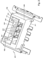
- the connector assembly 100 shown may be formed for example as a female connector, whereas the other connector part 200 - as shown - is designed as a male connector.
- spring contact elements 110 are provided in the male connector part 100 designed as a spring connector in a plug-in part 102 of the housing 101.
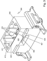
- knife contact elements 210 are arranged in a corresponding housing part 202 of the housing 201. The blade contact elements 210 can be plugged into correspondingly adapted spring contact elements 110 of the connector part 100.
- a latching tongue 300 hereinafter also referred to as tongue for short, is arranged, which has a latching nose 310.
- the locking lug 310 has a chamfer 312 in the insertion direction, which facilitates insertion into a opening 400 arranged in the housing 201 of the second connector part 200 and adapted to the latching tongue 300.
- the latching tongue 300 is resiliently formed, so that it bends slightly when inserted into the housing 201 of the second connector part 200 in the direction of the spring contact elements 110, which is facilitated by acting as a sliding surface chamfer 312 until the latch 310 is completely behind the opening 400 and rests with its detent end 313 at a housing wall receiving the opening 400 222.
- the two connector parts are locked together and a pulling apart is only possible by the tongue in turn in the direction of the spring contact elements 110, for example by means of a corresponding tool, is bent.
- the tongue 300 lies in a corresponding receiving pocket 500, which has a substantially U-shaped configuration with a surface 501 which extends substantially parallel to the tongue 300 and with lateral U-legs 510, 520.
- the U-legs 510, 520 project beyond the tongue 300, ie the tongue 300 lies completely, in particular in terms of their height, in the U-shaped region formed by the U-legs 510, 520 and the surface 501 of the thus formed in a sense first half of the tongue receiving pocket 500 (FIGS. Fig. 1 ).
- the second connector part 200 ( Fig. 2 ) has guide grooves 610, 620 which serve to guide the two U-shaped legs 510, 520. In this way, a very precise and reverse polarity nesting of the two connector parts is possible.
- the tongue 300 In the nested state of the two connector parts 100, 200, the tongue 300 is within the two housing parts, wherein the tongue receiving pocket 500 is formed by the U-shaped portion of the first connector part 100 and the two guide grooves 610, 620 of the second connector part 200 in conjunction with one opposite two groove webs 611, 621 slightly recessed surface 601 (FIG. Fig. 2 ).
- the two Nutstege 611, 621 together with the surface 601 and the two U-legs 510, 520 and the surface 501 form in the nested state of the two connector parts 100, 200, the tongue receiving pocket 500, in which the latching tongue 300 is arranged completely protected.
- the two U-shaped legs 510, 520 in conjunction with the two grooves 610, 620 and the corresponding groove legs 611, 621 but at the same time fulfill another very important task, which will be explained in more detail below.
- Both the U-legs 510, 520 and the two groove legs 611, 621 extend to the end face of the corresponding housing parts of the two connector parts 100, 200. They are relatively solid and prevent not only a misfire due to their design. They also prevent in particular a tilted nesting of the two connector parts 100, 200, they serve in other words, the training of so-called Koshiri security.
- a tongue receiving pocket 500 is formed, which not only the tongue 300 in the Locked state, but especially in the unlocked state of the two connector parts 100, 200 effectively protects each other.
- the U-shaped legs 510, 520 together with the surface 501 and the grooves 610, 620 together with the groove legs 611, 621 and the recessed surface 601 thus not only allow the formation of a tongue receiving pocket 500, but they also provide the Koshiri security the plug sure.
- Connector assembly shown comprises a connector part 200 which is arranged for example on a printed circuit board and contacted there with correspondingly provided conductor tracks, and a connector part 100 which is contacted for example with corresponding electrical conductors by means of known insulation displacement contacts.
- openings 170 are provided into which projects, for example, a ribbon cable or individual wires that in the connector part 100, for example, in the in the DE 10 2004 054 203 A1 described manner be contacted by insulation displacement terminals.
Landscapes
- Details Of Connecting Devices For Male And Female Coupling (AREA)
- Connector Housings Or Holding Contact Members (AREA)
Applications Claiming Priority (2)
| Application Number | Priority Date | Filing Date | Title |
|---|---|---|---|
| DE102012025107.6A DE102012025107A1 (de) | 2012-12-21 | 2012-12-21 | Steckverbinderanordnung |
| PCT/DE2013/000775 WO2014094706A1 (de) | 2012-12-21 | 2013-12-12 | Steckverbinderanordnung |
Publications (2)
| Publication Number | Publication Date |
|---|---|
| EP2936622A1 EP2936622A1 (de) | 2015-10-28 |
| EP2936622B1 true EP2936622B1 (de) | 2018-12-26 |
Family
ID=50151056
Family Applications (1)
| Application Number | Title | Priority Date | Filing Date |
|---|---|---|---|
| EP13831820.9A Active EP2936622B1 (de) | 2012-12-21 | 2013-12-12 | Steckverbinderanordnung |
Country Status (12)
| Country | Link |
|---|---|
| US (1) | US9478895B2 (he) |
| EP (1) | EP2936622B1 (he) |
| JP (2) | JP2016500467A (he) |
| KR (2) | KR20200000709U (he) |
| CN (1) | CN104871375B (he) |
| BR (1) | BR112015014126A2 (he) |
| DE (1) | DE102012025107A1 (he) |
| DK (1) | DK2936622T3 (he) |
| ES (1) | ES2717681T3 (he) |
| IL (1) | IL238980B (he) |
| MX (1) | MX2015007820A (he) |
| WO (1) | WO2014094706A1 (he) |
Families Citing this family (12)
| Publication number | Priority date | Publication date | Assignee | Title |
|---|---|---|---|---|
| DE102012025106A1 (de) * | 2012-12-21 | 2014-06-26 | Erni Production Gmbh & Co. Kg | Elektrischer Steckverbinder |
| DE102013012251A1 (de) * | 2013-07-24 | 2015-01-29 | Erni Production Gmbh & Co. Kg | Terminal zur Kontaktierung eines elektrischen Leiters |
| US9847610B2 (en) | 2014-01-16 | 2017-12-19 | Ford Global Technologies, Llc | Electric vehicle service disconnect position indicator |
| DE102014007352A1 (de) * | 2014-03-13 | 2015-09-17 | Dehn + Söhne Gmbh + Co. Kg | Überspannungsschutzeinrichtung mit mindestens einem Überspannungsschutzgerät |
| DE102014003477A1 (de) * | 2014-03-14 | 2015-09-17 | Erni Production Gmbh & Co. Kg | Verpolungsschutz |
| DE102014118685A1 (de) * | 2014-12-15 | 2016-06-16 | Erni Production Gmbh & Co. Kg | Hermetisch dichtender Steckverbinder |
| US9306327B1 (en) | 2015-04-17 | 2016-04-05 | Osram Sylvania Inc. | Clip for wire harness |
| US9281615B1 (en) | 2015-04-17 | 2016-03-08 | OSRAM SLYVANIA Inc. | Retainer clip for a wire harness |
| JP6610194B2 (ja) * | 2015-11-19 | 2019-11-27 | Smk株式会社 | コネクタ |
| US20170361110A1 (en) * | 2016-06-16 | 2017-12-21 | Boston Scientific Neuromodulation Corporation | Multi-Conductor Cable in an External Charger for an Implantable Medical Device |
| JP6404276B2 (ja) * | 2016-07-08 | 2018-10-10 | 矢崎総業株式会社 | コネクタの嵌合検知構造及びコネクタ |
| JP7164863B2 (ja) * | 2018-08-27 | 2022-11-02 | 日本圧着端子製造株式会社 | 電気コネクタ |
Citations (1)
| Publication number | Priority date | Publication date | Assignee | Title |
|---|---|---|---|---|
| US5203719A (en) * | 1990-12-14 | 1993-04-20 | Yazaki Corporation | Lock assurance mechanism for connector |
Family Cites Families (13)
| Publication number | Priority date | Publication date | Assignee | Title |
|---|---|---|---|---|
| JP3183382B2 (ja) * | 1995-10-16 | 2001-07-09 | 矢崎総業株式会社 | 電気コネクタ |
| JP3755677B2 (ja) * | 1996-05-10 | 2006-03-15 | 矢崎総業株式会社 | コネクタの嵌合構造 |
| JP3405954B2 (ja) * | 2000-03-13 | 2003-05-12 | 日本圧着端子製造株式会社 | コネクタのロック構造 |
| JP2002107571A (ja) * | 2000-09-27 | 2002-04-10 | Furukawa Electric Co Ltd:The | 光コネクタ |
| JP3879911B2 (ja) * | 2002-04-26 | 2007-02-14 | 矢崎総業株式会社 | コネクタの離脱構造 |
| JP2004327321A (ja) * | 2003-04-25 | 2004-11-18 | Jst Mfg Co Ltd | コネクタ |
| JP4029775B2 (ja) * | 2003-05-22 | 2008-01-09 | 住友電装株式会社 | コネクタ |
| DE102004054203A1 (de) | 2004-11-10 | 2006-05-11 | Erni Elektroapparate Gmbh | Schneidklemm-Steckkontaktleiste für elektrische Steckverbinder |
| KR100599313B1 (ko) * | 2004-11-12 | 2006-07-18 | 현대자동차주식회사 | 와이어하니스 커넥터 |
| JP2006147419A (ja) * | 2004-11-22 | 2006-06-08 | Sumitomo Wiring Syst Ltd | コネクタ |
| DE102008051589A1 (de) | 2007-10-16 | 2009-04-23 | Hirschmann Automotive Gmbh | Kuppler und Stecker einer Steckverbindung mit Koshiri-Sicherheit |
| US8052458B2 (en) * | 2009-09-25 | 2011-11-08 | Tyco Electronics Corporation | Electrical connector assembly |
| DE202011000739U1 (de) | 2011-03-31 | 2012-07-05 | Weidmüller Interface GmbH & Co. KG | Steckverbindungsanordnung für elektrische Leiter |
-
2012
- 2012-12-21 DE DE102012025107.6A patent/DE102012025107A1/de not_active Withdrawn
-
2013
- 2013-12-12 KR KR2020207000016U patent/KR20200000709U/ko not_active Ceased
- 2013-12-12 CN CN201380066988.5A patent/CN104871375B/zh active Active
- 2013-12-12 JP JP2015548193A patent/JP2016500467A/ja active Pending
- 2013-12-12 EP EP13831820.9A patent/EP2936622B1/de active Active
- 2013-12-12 ES ES13831820T patent/ES2717681T3/es active Active
- 2013-12-12 DK DK13831820.9T patent/DK2936622T3/en active
- 2013-12-12 US US14/654,056 patent/US9478895B2/en active Active
- 2013-12-12 MX MX2015007820A patent/MX2015007820A/es not_active Application Discontinuation
- 2013-12-12 WO PCT/DE2013/000775 patent/WO2014094706A1/de not_active Ceased
- 2013-12-12 KR KR1020157018718A patent/KR20150097617A/ko not_active Withdrawn
- 2013-12-12 BR BR112015014126A patent/BR112015014126A2/pt not_active IP Right Cessation
-
2015
- 2015-05-25 IL IL238980A patent/IL238980B/he active IP Right Grant
-
2018
- 2018-05-25 JP JP2018001928U patent/JP3218961U/ja not_active Expired - Lifetime
Patent Citations (1)
| Publication number | Priority date | Publication date | Assignee | Title |
|---|---|---|---|---|
| US5203719A (en) * | 1990-12-14 | 1993-04-20 | Yazaki Corporation | Lock assurance mechanism for connector |
Also Published As
| Publication number | Publication date |
|---|---|
| EP2936622A1 (de) | 2015-10-28 |
| DK2936622T3 (en) | 2019-04-15 |
| DE102012025107A1 (de) | 2014-06-26 |
| WO2014094706A1 (de) | 2014-06-26 |
| CA2893008A1 (en) | 2014-06-26 |
| CN104871375B (zh) | 2018-04-20 |
| CA2893008C (en) | 2020-10-13 |
| IL238980B (he) | 2019-01-31 |
| IL238980A0 (he) | 2015-07-30 |
| MX2015007820A (es) | 2015-10-29 |
| JP2016500467A (ja) | 2016-01-12 |
| CN104871375A (zh) | 2015-08-26 |
| US20150349451A1 (en) | 2015-12-03 |
| JP3218961U (ja) | 2018-11-22 |
| ES2717681T3 (es) | 2019-06-24 |
| KR20150097617A (ko) | 2015-08-26 |
| US9478895B2 (en) | 2016-10-25 |
| KR20200000709U (ko) | 2020-04-06 |
| BR112015014126A2 (pt) | 2017-07-11 |
Similar Documents
| Publication | Publication Date | Title |
|---|---|---|
| EP2936622B1 (de) | Steckverbinderanordnung | |
| DE102007026582B3 (de) | Steckverbindergehäuse mit einer Fixierung für ein elektrisches Kontaktelement und eine elektrische Leitung | |
| DE69700207T2 (de) | Modularer elekrischer Verbinder | |
| DE102018208434B4 (de) | Verbinder | |
| DE112018006109T5 (de) | Elektrischer verbinder mit anschlusspositionsgewährleistungselement | |
| EP2936621B1 (de) | Elektrischer steckverbinder | |
| DE102015201089A1 (de) | Zwischengehäuse mit einer CPA-Aufnahme und Steckverbindersysteme umfassend ein solches | |
| DE19828636A1 (de) | Steckverbinder mit Schnappverschluß | |
| DE102014225949A1 (de) | Elektrischer Steckverbinder mit Rasteinrichtung zur Kontaktierung eines Bipolarplattenstapels für eine Brennstoffzelle und Bipolarplattenstapel | |
| EP3588684A1 (de) | Direktstecker und direktsteckverbindung | |
| DE102013211208A1 (de) | Stecker und Steckverbinderanordnung | |
| DE102006043574A1 (de) | Solarsteckverbinder mit verbesserten Rastmitteln | |
| DE102011002135B4 (de) | Steckerelement mit zweiter Kontaktsicherung | |
| EP3117489B1 (de) | Modularer steckverbinder mit steckverbinderausrichtungsmodul | |
| EP1959523A1 (de) | Kodiereinrichtung für Steckverbinder | |
| DE102022105676A1 (de) | Gehäuse eines elektrischen Steckverbinders und elektrischer Steckverbinder | |
| DE102012218234B4 (de) | Verrastbarer Kontakt mit von Seitenwand übergriffener Primärverriegelungslanze | |
| DE102016217456B3 (de) | Anordnung für einen elektrischen Steckverbinder sowie Steckverbinder mit einem Kontaktgehäuse, Umgehäuse und Sicherungselement | |
| EP2054973A1 (de) | Stecker mit sekundärverriegelung für eine elektrische steckverbindung | |
| WO2013034443A1 (de) | Elektrischer verbinder mit berührschutz | |
| EP3504760B1 (de) | Mehrfachkontaktstecker mit integriertem kurzschlussbrückenelement | |
| DE9308144U1 (de) | Elektrischer Verbinder mit Primär- und Sekundärverriegelung der Kontaktelemente | |
| DE202012012261U1 (de) | Steckverbinderanordnung | |
| EP3756249A1 (de) | Steckverbinder mit polarisationselement sowie ein system und ein verfahren zum montieren, zum stecken und zum trennen dieses steckverbinders | |
| EP3117490B1 (de) | Verpolungsschutz |
Legal Events
| Date | Code | Title | Description |
|---|---|---|---|
| PUAI | Public reference made under article 153(3) epc to a published international application that has entered the european phase |
Free format text: ORIGINAL CODE: 0009012 |
|
| 17P | Request for examination filed |
Effective date: 20150624 |
|
| AK | Designated contracting states |
Kind code of ref document: A1 Designated state(s): AL AT BE BG CH CY CZ DE DK EE ES FI FR GB GR HR HU IE IS IT LI LT LU LV MC MK MT NL NO PL PT RO RS SE SI SK SM TR |
|
| AX | Request for extension of the european patent |
Extension state: BA ME |
|
| DAX | Request for extension of the european patent (deleted) | ||
| STAA | Information on the status of an ep patent application or granted ep patent |
Free format text: STATUS: EXAMINATION IS IN PROGRESS |
|
| 17Q | First examination report despatched |
Effective date: 20180103 |
|
| GRAP | Despatch of communication of intention to grant a patent |
Free format text: ORIGINAL CODE: EPIDOSNIGR1 |
|
| STAA | Information on the status of an ep patent application or granted ep patent |
Free format text: STATUS: GRANT OF PATENT IS INTENDED |
|
| RIC1 | Information provided on ipc code assigned before grant |
Ipc: H01R 13/627 20060101AFI20180612BHEP Ipc: H01R 13/64 20060101ALI20180612BHEP Ipc: H01R 13/506 20060101ALI20180612BHEP |
|
| INTG | Intention to grant announced |
Effective date: 20180704 |
|
| GRAJ | Information related to disapproval of communication of intention to grant by the applicant or resumption of examination proceedings by the epo deleted |
Free format text: ORIGINAL CODE: EPIDOSDIGR1 |
|
| STAA | Information on the status of an ep patent application or granted ep patent |
Free format text: STATUS: EXAMINATION IS IN PROGRESS |
|
| GRAR | Information related to intention to grant a patent recorded |
Free format text: ORIGINAL CODE: EPIDOSNIGR71 |
|
| GRAS | Grant fee paid |
Free format text: ORIGINAL CODE: EPIDOSNIGR3 |
|
| STAA | Information on the status of an ep patent application or granted ep patent |
Free format text: STATUS: GRANT OF PATENT IS INTENDED |
|
| INTC | Intention to grant announced (deleted) | ||
| GRAA | (expected) grant |
Free format text: ORIGINAL CODE: 0009210 |
|
| STAA | Information on the status of an ep patent application or granted ep patent |
Free format text: STATUS: THE PATENT HAS BEEN GRANTED |
|
| INTG | Intention to grant announced |
Effective date: 20181113 |
|
| AK | Designated contracting states |
Kind code of ref document: B1 Designated state(s): AL AT BE BG CH CY CZ DE DK EE ES FI FR GB GR HR HU IE IS IT LI LT LU LV MC MK MT NL NO PL PT RO RS SE SI SK SM TR |
|
| REG | Reference to a national code |
Ref country code: GB Ref legal event code: FG4D Free format text: NOT ENGLISH |
|
| REG | Reference to a national code |
Ref country code: CH Ref legal event code: EP |
|
| REG | Reference to a national code |
Ref country code: AT Ref legal event code: REF Ref document number: 1082725 Country of ref document: AT Kind code of ref document: T Effective date: 20190115 |
|
| REG | Reference to a national code |
Ref country code: DE Ref legal event code: R096 Ref document number: 502013011935 Country of ref document: DE |
|
| REG | Reference to a national code |
Ref country code: IE Ref legal event code: FG4D Free format text: LANGUAGE OF EP DOCUMENT: GERMAN |
|
| REG | Reference to a national code |
Ref country code: DK Ref legal event code: T3 Effective date: 20190408 |
|
| REG | Reference to a national code |
Ref country code: SE Ref legal event code: TRGR |
|
| PG25 | Lapsed in a contracting state [announced via postgrant information from national office to epo] |
Ref country code: LV Free format text: LAPSE BECAUSE OF FAILURE TO SUBMIT A TRANSLATION OF THE DESCRIPTION OR TO PAY THE FEE WITHIN THE PRESCRIBED TIME-LIMIT Effective date: 20181226 Ref country code: LT Free format text: LAPSE BECAUSE OF FAILURE TO SUBMIT A TRANSLATION OF THE DESCRIPTION OR TO PAY THE FEE WITHIN THE PRESCRIBED TIME-LIMIT Effective date: 20181226 Ref country code: BG Free format text: LAPSE BECAUSE OF FAILURE TO SUBMIT A TRANSLATION OF THE DESCRIPTION OR TO PAY THE FEE WITHIN THE PRESCRIBED TIME-LIMIT Effective date: 20190326 Ref country code: HR Free format text: LAPSE BECAUSE OF FAILURE TO SUBMIT A TRANSLATION OF THE DESCRIPTION OR TO PAY THE FEE WITHIN THE PRESCRIBED TIME-LIMIT Effective date: 20181226 |
|
| REG | Reference to a national code |
Ref country code: CH Ref legal event code: NV Representative=s name: RENTSCH PARTNER AG, CH |
|
| REG | Reference to a national code |
Ref country code: NL Ref legal event code: FP |
|
| REG | Reference to a national code |
Ref country code: LT Ref legal event code: MG4D |
|
| PG25 | Lapsed in a contracting state [announced via postgrant information from national office to epo] |
Ref country code: AL Free format text: LAPSE BECAUSE OF FAILURE TO SUBMIT A TRANSLATION OF THE DESCRIPTION OR TO PAY THE FEE WITHIN THE PRESCRIBED TIME-LIMIT Effective date: 20181226 Ref country code: GR Free format text: LAPSE BECAUSE OF FAILURE TO SUBMIT A TRANSLATION OF THE DESCRIPTION OR TO PAY THE FEE WITHIN THE PRESCRIBED TIME-LIMIT Effective date: 20190327 Ref country code: RS Free format text: LAPSE BECAUSE OF FAILURE TO SUBMIT A TRANSLATION OF THE DESCRIPTION OR TO PAY THE FEE WITHIN THE PRESCRIBED TIME-LIMIT Effective date: 20181226 |
|
| REG | Reference to a national code |
Ref country code: NO Ref legal event code: T2 Effective date: 20181226 |
|
| REG | Reference to a national code |
Ref country code: ES Ref legal event code: FG2A Ref document number: 2717681 Country of ref document: ES Kind code of ref document: T3 Effective date: 20190624 |
|
| PG25 | Lapsed in a contracting state [announced via postgrant information from national office to epo] |
Ref country code: PT Free format text: LAPSE BECAUSE OF FAILURE TO SUBMIT A TRANSLATION OF THE DESCRIPTION OR TO PAY THE FEE WITHIN THE PRESCRIBED TIME-LIMIT Effective date: 20190426 Ref country code: CZ Free format text: LAPSE BECAUSE OF FAILURE TO SUBMIT A TRANSLATION OF THE DESCRIPTION OR TO PAY THE FEE WITHIN THE PRESCRIBED TIME-LIMIT Effective date: 20181226 Ref country code: PL Free format text: LAPSE BECAUSE OF FAILURE TO SUBMIT A TRANSLATION OF THE DESCRIPTION OR TO PAY THE FEE WITHIN THE PRESCRIBED TIME-LIMIT Effective date: 20181226 |
|
| PG25 | Lapsed in a contracting state [announced via postgrant information from national office to epo] |
Ref country code: IS Free format text: LAPSE BECAUSE OF FAILURE TO SUBMIT A TRANSLATION OF THE DESCRIPTION OR TO PAY THE FEE WITHIN THE PRESCRIBED TIME-LIMIT Effective date: 20190426 Ref country code: SM Free format text: LAPSE BECAUSE OF FAILURE TO SUBMIT A TRANSLATION OF THE DESCRIPTION OR TO PAY THE FEE WITHIN THE PRESCRIBED TIME-LIMIT Effective date: 20181226 Ref country code: EE Free format text: LAPSE BECAUSE OF FAILURE TO SUBMIT A TRANSLATION OF THE DESCRIPTION OR TO PAY THE FEE WITHIN THE PRESCRIBED TIME-LIMIT Effective date: 20181226 Ref country code: RO Free format text: LAPSE BECAUSE OF FAILURE TO SUBMIT A TRANSLATION OF THE DESCRIPTION OR TO PAY THE FEE WITHIN THE PRESCRIBED TIME-LIMIT Effective date: 20181226 Ref country code: SK Free format text: LAPSE BECAUSE OF FAILURE TO SUBMIT A TRANSLATION OF THE DESCRIPTION OR TO PAY THE FEE WITHIN THE PRESCRIBED TIME-LIMIT Effective date: 20181226 |
|
| REG | Reference to a national code |
Ref country code: DE Ref legal event code: R097 Ref document number: 502013011935 Country of ref document: DE |
|
| PLBE | No opposition filed within time limit |
Free format text: ORIGINAL CODE: 0009261 |
|
| STAA | Information on the status of an ep patent application or granted ep patent |
Free format text: STATUS: NO OPPOSITION FILED WITHIN TIME LIMIT |
|
| 26N | No opposition filed |
Effective date: 20190927 |
|
| PG25 | Lapsed in a contracting state [announced via postgrant information from national office to epo] |
Ref country code: SI Free format text: LAPSE BECAUSE OF FAILURE TO SUBMIT A TRANSLATION OF THE DESCRIPTION OR TO PAY THE FEE WITHIN THE PRESCRIBED TIME-LIMIT Effective date: 20181226 |
|
| PG25 | Lapsed in a contracting state [announced via postgrant information from national office to epo] |
Ref country code: TR Free format text: LAPSE BECAUSE OF FAILURE TO SUBMIT A TRANSLATION OF THE DESCRIPTION OR TO PAY THE FEE WITHIN THE PRESCRIBED TIME-LIMIT Effective date: 20181226 |
|
| PG25 | Lapsed in a contracting state [announced via postgrant information from national office to epo] |
Ref country code: MC Free format text: LAPSE BECAUSE OF FAILURE TO SUBMIT A TRANSLATION OF THE DESCRIPTION OR TO PAY THE FEE WITHIN THE PRESCRIBED TIME-LIMIT Effective date: 20181226 |
|
| PG25 | Lapsed in a contracting state [announced via postgrant information from national office to epo] |
Ref country code: LU Free format text: LAPSE BECAUSE OF NON-PAYMENT OF DUE FEES Effective date: 20191212 |
|
| PG25 | Lapsed in a contracting state [announced via postgrant information from national office to epo] |
Ref country code: CY Free format text: LAPSE BECAUSE OF FAILURE TO SUBMIT A TRANSLATION OF THE DESCRIPTION OR TO PAY THE FEE WITHIN THE PRESCRIBED TIME-LIMIT Effective date: 20181226 |
|
| PG25 | Lapsed in a contracting state [announced via postgrant information from national office to epo] |
Ref country code: HU Free format text: LAPSE BECAUSE OF FAILURE TO SUBMIT A TRANSLATION OF THE DESCRIPTION OR TO PAY THE FEE WITHIN THE PRESCRIBED TIME-LIMIT; INVALID AB INITIO Effective date: 20131212 Ref country code: MT Free format text: LAPSE BECAUSE OF FAILURE TO SUBMIT A TRANSLATION OF THE DESCRIPTION OR TO PAY THE FEE WITHIN THE PRESCRIBED TIME-LIMIT Effective date: 20181226 |
|
| PG25 | Lapsed in a contracting state [announced via postgrant information from national office to epo] |
Ref country code: MK Free format text: LAPSE BECAUSE OF FAILURE TO SUBMIT A TRANSLATION OF THE DESCRIPTION OR TO PAY THE FEE WITHIN THE PRESCRIBED TIME-LIMIT Effective date: 20181226 |
|
| PGFP | Annual fee paid to national office [announced via postgrant information from national office to epo] |
Ref country code: NO Payment date: 20231212 Year of fee payment: 11 Ref country code: IT Payment date: 20231110 Year of fee payment: 11 Ref country code: FI Payment date: 20231218 Year of fee payment: 11 Ref country code: DK Payment date: 20231214 Year of fee payment: 11 Ref country code: AT Payment date: 20231127 Year of fee payment: 11 |
|
| PGFP | Annual fee paid to national office [announced via postgrant information from national office to epo] |
Ref country code: CH Payment date: 20240101 Year of fee payment: 11 |
|
| PGFP | Annual fee paid to national office [announced via postgrant information from national office to epo] |
Ref country code: NL Payment date: 20241004 Year of fee payment: 12 |
|
| PGFP | Annual fee paid to national office [announced via postgrant information from national office to epo] |
Ref country code: DE Payment date: 20241001 Year of fee payment: 12 |
|
| PGFP | Annual fee paid to national office [announced via postgrant information from national office to epo] |
Ref country code: BE Payment date: 20241007 Year of fee payment: 12 |
|
| PGFP | Annual fee paid to national office [announced via postgrant information from national office to epo] |
Ref country code: GB Payment date: 20241001 Year of fee payment: 12 |
|
| PGFP | Annual fee paid to national office [announced via postgrant information from national office to epo] |
Ref country code: FR Payment date: 20241001 Year of fee payment: 12 |
|
| PGFP | Annual fee paid to national office [announced via postgrant information from national office to epo] |
Ref country code: IE Payment date: 20241001 Year of fee payment: 12 |
|
| PGFP | Annual fee paid to national office [announced via postgrant information from national office to epo] |
Ref country code: SE Payment date: 20241010 Year of fee payment: 12 |
|
| PGFP | Annual fee paid to national office [announced via postgrant information from national office to epo] |
Ref country code: ES Payment date: 20250120 Year of fee payment: 12 |
|
| PG25 | Lapsed in a contracting state [announced via postgrant information from national office to epo] |
Ref country code: FI Free format text: LAPSE BECAUSE OF NON-PAYMENT OF DUE FEES Effective date: 20241212 |
|
| REG | Reference to a national code |
Ref country code: DK Ref legal event code: EBP Effective date: 20241231 |
|
| REG | Reference to a national code |
Ref country code: CH Ref legal event code: PL |
|
| REG | Reference to a national code |
Ref country code: AT Ref legal event code: MM01 Ref document number: 1082725 Country of ref document: AT Kind code of ref document: T Effective date: 20241212 |
|
| PG25 | Lapsed in a contracting state [announced via postgrant information from national office to epo] |
Ref country code: IT Free format text: LAPSE BECAUSE OF NON-PAYMENT OF DUE FEES Effective date: 20241212 Ref country code: NO Free format text: LAPSE BECAUSE OF NON-PAYMENT OF DUE FEES Effective date: 20241231 |
|
| PG25 | Lapsed in a contracting state [announced via postgrant information from national office to epo] |
Ref country code: AT Free format text: LAPSE BECAUSE OF NON-PAYMENT OF DUE FEES Effective date: 20241212 |
|
| PG25 | Lapsed in a contracting state [announced via postgrant information from national office to epo] |
Ref country code: CH Free format text: LAPSE BECAUSE OF NON-PAYMENT OF DUE FEES Effective date: 20241231 |