EP2934392B1 - Prosthetic valves, frames and leaflets - Google Patents
Prosthetic valves, frames and leaflets Download PDFInfo
- Publication number
- EP2934392B1 EP2934392B1 EP13824700.2A EP13824700A EP2934392B1 EP 2934392 B1 EP2934392 B1 EP 2934392B1 EP 13824700 A EP13824700 A EP 13824700A EP 2934392 B1 EP2934392 B1 EP 2934392B1
- Authority
- EP
- European Patent Office
- Prior art keywords
- leaflet
- frame
- base
- film
- valve
- Prior art date
- Legal status (The legal status is an assumption and is not a legal conclusion. Google has not performed a legal analysis and makes no representation as to the accuracy of the status listed.)
- Active
Links
Images


Classifications
-
- A—HUMAN NECESSITIES
- A61—MEDICAL OR VETERINARY SCIENCE; HYGIENE
- A61F—FILTERS IMPLANTABLE INTO BLOOD VESSELS; PROSTHESES; DEVICES PROVIDING PATENCY TO, OR PREVENTING COLLAPSING OF, TUBULAR STRUCTURES OF THE BODY, e.g. STENTS; ORTHOPAEDIC, NURSING OR CONTRACEPTIVE DEVICES; FOMENTATION; TREATMENT OR PROTECTION OF EYES OR EARS; BANDAGES, DRESSINGS OR ABSORBENT PADS; FIRST-AID KITS
- A61F2/00—Filters implantable into blood vessels; Prostheses, i.e. artificial substitutes or replacements for parts of the body; Appliances for connecting them with the body; Devices providing patency to, or preventing collapsing of, tubular structures of the body, e.g. stents
- A61F2/02—Prostheses implantable into the body
- A61F2/24—Heart valves ; Vascular valves, e.g. venous valves; Heart implants, e.g. passive devices for improving the function of the native valve or the heart muscle; Transmyocardial revascularisation [TMR] devices; Valves implantable in the body
- A61F2/2412—Heart valves ; Vascular valves, e.g. venous valves; Heart implants, e.g. passive devices for improving the function of the native valve or the heart muscle; Transmyocardial revascularisation [TMR] devices; Valves implantable in the body with soft flexible valve members, e.g. tissue valves shaped like natural valves
- A61F2/2415—Manufacturing methods
-
- A—HUMAN NECESSITIES
- A61—MEDICAL OR VETERINARY SCIENCE; HYGIENE
- A61F—FILTERS IMPLANTABLE INTO BLOOD VESSELS; PROSTHESES; DEVICES PROVIDING PATENCY TO, OR PREVENTING COLLAPSING OF, TUBULAR STRUCTURES OF THE BODY, e.g. STENTS; ORTHOPAEDIC, NURSING OR CONTRACEPTIVE DEVICES; FOMENTATION; TREATMENT OR PROTECTION OF EYES OR EARS; BANDAGES, DRESSINGS OR ABSORBENT PADS; FIRST-AID KITS
- A61F2/00—Filters implantable into blood vessels; Prostheses, i.e. artificial substitutes or replacements for parts of the body; Appliances for connecting them with the body; Devices providing patency to, or preventing collapsing of, tubular structures of the body, e.g. stents
- A61F2/02—Prostheses implantable into the body
- A61F2/24—Heart valves ; Vascular valves, e.g. venous valves; Heart implants, e.g. passive devices for improving the function of the native valve or the heart muscle; Transmyocardial revascularisation [TMR] devices; Valves implantable in the body
- A61F2/2412—Heart valves ; Vascular valves, e.g. venous valves; Heart implants, e.g. passive devices for improving the function of the native valve or the heart muscle; Transmyocardial revascularisation [TMR] devices; Valves implantable in the body with soft flexible valve members, e.g. tissue valves shaped like natural valves
- A61F2/2418—Scaffolds therefor, e.g. support stents
-
- A—HUMAN NECESSITIES
- A61—MEDICAL OR VETERINARY SCIENCE; HYGIENE
- A61F—FILTERS IMPLANTABLE INTO BLOOD VESSELS; PROSTHESES; DEVICES PROVIDING PATENCY TO, OR PREVENTING COLLAPSING OF, TUBULAR STRUCTURES OF THE BODY, e.g. STENTS; ORTHOPAEDIC, NURSING OR CONTRACEPTIVE DEVICES; FOMENTATION; TREATMENT OR PROTECTION OF EYES OR EARS; BANDAGES, DRESSINGS OR ABSORBENT PADS; FIRST-AID KITS
- A61F2230/00—Geometry of prostheses classified in groups A61F2/00 - A61F2/26 or A61F2/82 or A61F9/00 or A61F11/00 or subgroups thereof
- A61F2230/0002—Two-dimensional shapes, e.g. cross-sections
- A61F2230/0017—Angular shapes
- A61F2230/0023—Angular shapes triangular
-
- A—HUMAN NECESSITIES
- A61—MEDICAL OR VETERINARY SCIENCE; HYGIENE
- A61F—FILTERS IMPLANTABLE INTO BLOOD VESSELS; PROSTHESES; DEVICES PROVIDING PATENCY TO, OR PREVENTING COLLAPSING OF, TUBULAR STRUCTURES OF THE BODY, e.g. STENTS; ORTHOPAEDIC, NURSING OR CONTRACEPTIVE DEVICES; FOMENTATION; TREATMENT OR PROTECTION OF EYES OR EARS; BANDAGES, DRESSINGS OR ABSORBENT PADS; FIRST-AID KITS
- A61F2230/00—Geometry of prostheses classified in groups A61F2/00 - A61F2/26 or A61F2/82 or A61F9/00 or A61F11/00 or subgroups thereof
- A61F2230/0002—Two-dimensional shapes, e.g. cross-sections
- A61F2230/0017—Angular shapes
- A61F2230/0026—Angular shapes trapezoidal
Definitions
- the present disclosure relates generally to prosthetic heart valves and more specifically synthetic flexible leaflet-type prosthetic heart valve devices, systems, and methods.
- Bioprosthetic heart valves have been developed that attempt to mimic the function and performance of a native valve.
- Flexible leaflets are fabricated from biological tissue such as bovine pericardium.
- biological tissue such as bovine pericardium.
- the biological tissue is sewn onto a relatively rigid frame that supports the leaflets and provides dimensional stability when implanted.
- bioprosthetic heart valves can provide excellent hemodynamic and biomechanical performance in the short term, they are prone to calcification and cusp tears, among other failure modes, requiring reoperation and replacement.
- synthetic leaflet prosthetic heart valve Attempts have been made to use synthetic materials, such as polyurethane, among others, as a substitute for the biological tissue, to provide a more durable flexible leaflet prosthetic heart valve, herein referred to as a synthetic leaflet prosthetic heart valve (SLV).
- synthetic leaflet prosthetic heart valves have not become a valid heart valve replacement option since they suffer premature failure, due to, among other things, suboptimal design and lack of a durable synthetic material.
- the leaflet moves under the influence of fluid pressure.
- the leaflets open when the upstream fluid pressure exceeds the downstream fluid pressure and close when the downstream fluid pressure exceeds the upstream fluid pressure.
- the leaflet free edges of the leaflets coapt under the influence of downstream fluid pressure closing the prosthetic heart valve to prevent downstream blood from flowing retrograde through the prosthetic heart valve.
- Prosthetic heart valve durability under the repetitive loads of the leaflets opening and closing is dependent, in part, on the load distribution between the leaflet and the frame. Further, substantial load is encountered on the leaflet when in the closed position. Mechanical failure of the leaflet can arise, for example, at the mounting edge, where the flexible leaflet is supported by the relatively rigid frame. The repetitive loads of leaflet opening and closing leads to material failure by fatigue, creep or other mechanism, depending in part on the leaflet material. Mechanical failure at the mounting edge is especially prevalent with synthetic leaflets.
- the durability of the valve leaflets is also a function of the character of bending by the leaflet during the opening-closing cycle. Small radius bends, creases and intersecting creases, can produce high stress zones in the leaflet. These high stress zones can cause the formation of holes and tears under repetitive loading.
- Prosthetic heart valves may be delivered using surgical or transcatheter techniques.
- a surgical prosthetic heart valve is implanted into a patient using open-heart surgical techniques.
- the surgical prosthetic heart valve is usually manufactured to have a fixed diameter as opposed to a transcatheter prosthetic heart valve which is required to attain a range of diameters for access and delivery.
- the surgical prosthetic heart valve is usually provided with a sewing cuff about a perimeter of the prosthetic heart valve to allow for suturing to the native tissue orifice.
- transcatheter prosthetic heart valve In addition to the prosthetic heart valve durability issues discussed above, the transcatheter prosthetic heart valve must also be able to withstand the handling and deployment stresses associated with being compressed and expanded.
- a preferred shape of synthetic prosthetic heart valve leaflets has been described many times, but each is different from the others.
- the various three-dimensional shapes range from spherical or cylindrical to truncated conical intersections with spheres and an "alpharabola".
- the shape most often described as preferable is modeled after the native human aortic valve. Though nature dictates the optimum shape for the native tissues to form a heart valve, we have discovered this is not true for synthetic materials; accordingly, the design specified in the current disclosure is instead intended to place the synthetic material under a minimized stress condition as compared to those based on copies of the native valve. This is partially accomplished through reduced buckling in the leaflet material.
- US 2010/0262231 (Tuval et al. ) describes a valve prosthesis having inner and outer frames structures.
- the inner frame has a "skirt" to which a graft covering is attached.
- a valve is formed at the distal end of the prosthesis from a pliant material, which is sewn to the graft covering and the commissural posts.
- a prosthetic valve comprises a leaflet frame having a generally tubular shape, an outer frame having a generally tubular shape, and a film.
- film as used herein generically refers to one or more of a membrane, composite material, or laminate.
- the leaflet frame and outer frame are coupled at least in part by a contiguous portion of the film.
- the leaflet frame defines a plurality of leaflet windows, wherein the film defines a leaflet extending from each of the leaflet windows.
- a prosthetic valve comprises a leaflet frame having a generally tubular shape and an outer frame having a generally tubular shape.
- the leaflet frame and outer frame are coupled together by a contiguous portion of a film in which the leaflet frame is nested into the outer frame in a telescoping manner.
- the leaflet frame defines a plurality of leaflet windows, wherein the film defines a leaflet extending from each of the leaflet windows.
- a prosthetic valve comprises a leaflet frame having a generally tubular shape, an outer frame having a generally tubular shape, and film.
- the leaflet frame is coaxially disposed at least partially within the outer frame.
- the outer frame provides frame elements that overlay leaflet windows that are defined by the leaflet frame so as to provide structural support over the leaflet windows, as shown in FIGs. 1A-1B .
- the leaflet frame defines a plurality of leaflet windows, wherein the film defines a leaflet extending from each of the leaflet windows.
- a prosthetic valve comprises a leaflet frame having a generally tubular shape, an outer frame having a generally tubular shape, and film.
- the leaflet frame defines a plurality of leaflet windows.
- the film defines at least one leaflet extending from each of the leaflet windows.
- Each leaflet has substantially the shape of an isosceles trapezoid having two leaflet sides, a leaflet base and a free edge opposite the leaflet base. The two leaflet sides diverge from the leaflet base, wherein the leaflet base is substantially flat.
- each leaflet includes a central region and two side regions on opposite sides of the central region.
- the central region is defined by a shape substantially that of an isosceles trapezoid defined by two central region sides, the leaflet base and the leaflet free edge.
- the two central region sides converge from the leaflet base.
- Each of the side regions has a shape substantially that of a triangle and each are defined by one of the central region sides, one of the leaflet sides, and the leaflet free edge.
- each leaflet includes a central region and two side regions on opposite sides of the central region.
- the central region is defined by a shape substantially that of an isosceles triangle defined by two central region sides, the leaflet base and the leaflet free edge.
- the two central region sides converge from the leaflet base to the free edge.
- Each of the side regions has a shape substantially that of a triangle and each are defined by one of the central region sides, one of the leaflet sides, and the leaflet free edge.
- Each of the two side regions and the central region are substantially planar when the valve is in the closed position and under no pressure load.
- the frame comprises a frame first end and a frame second end opposite the frame first end, the leaflet window having a shape determined, at least in part, by wrapping a two dimensional isosceles trapezoid onto the tubular shape of the frame, the isosceles trapezoid having a base and two sides that diverge from the base, and wherein a side from adjacent isosceles trapezoids meet at the frame second end.
- the leaflets defining a shape of a trapezoid wherein frame elements bounds two sides, one side being a free edge, and the leaflet base being is a horizontal truncation bound only by the film.
- the film defining at least one leaflet is coupled to an outer surface of the leaflet frame.
- the film defining at least one leaflet is coupled to an inner surface of the leaflet frame.
- the leaflet frame and outer frame are coupled at least in part by a contiguous portion of the film.
- the outer frame provides frame elements that overlay leaflet windows that are defined by the leaflet frame so as to provide structural support over the leaflet windows.
- the outer frame provides frame elements that overlay the leaflet windows that are defined by the leaflet frame, wherein the leaflet frame and outer frame present a substantially uniform geometric pattern of frame elements that act in concert so as to enable the frame assembly to compress and expand substantially uniformly when compressed and expanded for transcatheter applications.
- the film is disposed between the leaflet frame and the outer frame.
- the leaflet frame and outer frame are separated by the film and are not in contact with each other.
- each leaflet has a substantially flat leaflet base.
- the leaflet frame defines three interconnected leaflet windows having a substantially triangular shape.
- the prosthetic valve comprises a leaflet frame having a generally tubular shape, an outer frame having a generally tubular shape, and a film.
- the leaflet frame is coaxially disposed at least partially within the outer frame.
- the leaflet frame and outer frame are coupled at least in part by a contiguous portion of the film.
- the leaflet frame defines a plurality of leaflet windows
- the film defines a leaflet extending from each of the leaflet windows.
- a leaflet window side of one leaflet window is interconnected with a leaflet window side of an adjacent leaflet window.
- each leaflet has substantially the shape of an isosceles trapezoid having two leaflet sides, a leaflet base and a free edge opposite the leaflet base, wherein the two leaflet sides diverge from the leaflet base, wherein the leaflet base is substantially flat.
- the leaflet window is defined by window frame elements corresponding to the leaflet sides and leaflet base, wherein the film is coupled to the window frame elements and extends across the leaflet window defining the leaflet.
- the film extends across the leaflet window defining a bending region and a support region separated by a bending interface, wherein the leaflet bends within the bending region when cycled between an open and closed position, wherein the bending interface defines the leaflet base and sides having substantially the shape of an isosceles trapezoid.
- the bending interface is collocated with the leaflet window sides.
- the bending interface is collocated with the leaflet window sides and leaflet window base.
- the bending interface is spaced apart from and not collocated with the leaflet window base.
- the bending interface is spaced apart from and not collocated with the leaflet window sides and leaflet window base.
- the bending interface is collocated with a portion of the leaflet window sides.
- the bending interface defines the leaflet base and sides having the shape of an isosceles trapezoid.
- the frame comprises a plurality of spaced apart leaflet windows each defining substantially an isosceles triangle interconnected by a base element, wherein each leaflet window side is defined by a side of one triangle and a side of an adjacent triangle, and wherein each leaflet window base is defined by the base element.
- the frame comprises a base element and a plurality of spaced apart spade elements interconnected by the base element, wherein each leaflet window is defined by a side of one spade element and a side of an adjacent spade element, and wherein each leaflet window base is defined by the base element.
- the frame comprises a plurality of spaced apart interconnected leaflet windows each defining substantially isosceles triangles, wherein each leaflet window side is defined by a side of one triangle and a side of an adjacent triangle, and wherein each leaflet window base is defined by the base element.
- the prosthetic valve comprises a collapsed configuration and an expanded configuration for transcatheter delivery.
- the leaflet is moveable between an open and closed position.
- the leaflet comprises a polymeric film.
- the leaflet comprises a laminate.
- the laminate has more than one layer of a fluoropolymer membrane.
- the leaflet comprises a film having at least one fluoropolymer membrane layer having a plurality of pores and an elastomer present in substantially all of the pores of at least one layer of fluoropolymer membrane.
- the film comprises less than about 80% fluoropolymer membrane by weight.
- the elastomer comprises (per)fluoroalkylvinylethers (PAVE).
- the elastomer comprises a copolymer of tetrafluoroethylene and perfluoromethyl vinyl ether.
- the fluoropolymer membrane comprises ePTFE.
- the leaflet frame and/or outer frame is defines a generally open pattern of apertures operable to allow the outer frame to be compressed and expanded between different diameters.
- an aspect ratio of a length of the valve to a diameter of the valve is less than 1.
- the valve is less than about 20 mm in length.
- the leaflet frame and/or outer frame comprise a shape memory film.
- the leaflet frame and/or outer frame comprises a metallic film.
- in a collapsed configuration has a collapsed profile less than about 6mm.
- the valve is balloon expandable.
- the film sandwiches the outer frame and the leaflet frame.
- a prosthetic valve comprises a plurality of leaflets, each leaflet having a shape substantially that of an isosceles trapezoid having two leaflet sides, a leaflet base, and a free edge opposite the leaflet base, wherein the two leaflet sides diverge from the leaflet base.
- a prosthetic valve comprises a plurality of leaflets, wherein, wherein each leaflet includes a central region and two side regions on opposite sides of the central region, wherein the central region is defined by a shape substantially that of an isosceles triangle defined by two central region sides, the leaflet base and the leaflet free edge, wherein the two central region sides converge from the leaflet base, and wherein each of the side regions have a shape substantially that of a triangle and each are defined by one of the central region sides, one of the leaflet sides, and the leaflet free edge.
- a prosthetic valve comprises a leaflet frame, an outer frame, and a film.
- the leaflet frame has a generally tubular shape defining a plurality of leaflet windows.
- the outer frame has a generally tubular shape.
- the leaflet frame is coaxially disposed at least partially within the outer frame.
- the leaflet frame and outer frame are coupled at least in part by a contiguous portion of the film. At least a portion of the contiguous portion of the film is contained between and coupling the leaflet frame and outer frame operable to prevent relative movement and contact therebetween.
- the film defines a leaflet extending from each of the leaflet windows.
- a prosthetic valve comprises and leaflet frame, and outer frame and a film.
- the leaflet frame has a generally tubular shape defining a plurality of leaflet windows.
- the outer frame has a generally tubular shape.
- the leaflet frame is coaxially disposed at least partially within the outer frame.
- the outer frame includes frame elements that overlay the leaflet windows that are defined by the leaflet frame in cooperative arrangement so as to provide structural support over the leaflet windows.
- the film defines a leaflet extending from each of the leaflet windows.
- a method of making a prosthetic valve comprises: wrapping a first layer of film into a tubular form about a mandrel; providing a leaflet frame having a generally tubular shape, the leaflet frame having a leaflet frame leaflet surface and a leaflet frame outer surface, the leaflet frame defining a plurality of leaflet windows having a window top; providing an outer frame having a generally tubular shape, the outer frame having an outer frame leaflet surface and an outer frame outer surface; placing the leaflet frame and the outer frame over the first layer of film with the leaflet frame and outer frame spaced apart from each other defining a bridge portion therebetween, the leaflet frame inner surface and the outer frame inner surface in contact with the first layer of film; forming a second layer of film over the leaflet frame and the outer frame in contact with the leaflet frame outer surface and the outer frame outer surface; coupling the first layer of film and the second layer of film to each other and to the leaflet frame and the outer frame; cutting the first layer of film and the second layer
- Some embodiments are directed toward flexible leaflet valve devices in which the leaflets are divided into zones, each with a particular geometry.
- a prosthetic valve comprises a plurality of leaflets, each leaflet defining two side regions and a central region between the side regions, the central region having a shape that is different from that of the side regions.
- a prosthetic valve comprises a leaflet frame and a film.
- the leaflet frame has a generally tubular shape.
- the leaflet frame defines a plurality of leaflet windows wherein each of the leaflet windows includes two leaflet window sides, a leaflet window base, and a leaflet window top.
- the film being coupled to the leaflet frame and defining at least one leaflet extending from each of the leaflet windows, wherein each leaflet has substantially the shape of an isosceles trapezoid having two leaflet sides, a leaflet base and a free edge opposite the leaflet base, wherein the two leaflet sides diverge from the leaflet base, and wherein the leaflet base is substantially flat.
- the leaflet base is coupled to the window base and each of the two leaflet sides are coupled to one of the two window sides.
- a prosthetic valve comprises a plurality of leaflets.
- Each leaflet includes a central region and two side regions on opposite sides of the central region.
- the central region is defined by a shape substantially that of an isosceles triangle defined by two central region sides, the leaflet base and the leaflet free edge, wherein the two central region sides converge from the leaflet base, and wherein each of the side regions have a shape substantially that of a triangle and each are defined by one of the central region sides, one of the leaflet sides, and the leaflet free edge.
- a method of forming a prosthetic heart valve comprises providing a leaflet frame having a generally tubular shape, the leaflet frame defining a plurality of leaflet windows wherein each of the leaflet windows includes two leaflet window sides, a leaflet window base, and a leaflet window top; providing a film, and wrapping the film about the leaflet frame bringing more than one layer of the film into contact with additional layers of the film defining at least one leaflet extending from each of the leaflet windows, wherein each leaflet has substantially the shape of an isosceles trapezoid having two leaflet sides, a leaflet base and a free edge opposite the leaflet base, wherein the two leaflet sides diverge from the leaflet base, wherein the leaflet base is substantially flat; wherein the leaflet base is coupled to the window base and wherein each of the two leaflet sides are coupled to one of the two window sides providing a generally annular support structure; and bonding the layers of film to itself and to the leaflet frame.
- a method of forming a prosthetic heart valve comprises providing a leaflet frame having a generally tubular shape, the leaflet frame defining a plurality of leaflet windows wherein each of the leaflet windows includes two leaflet window sides, a leaflet window base, and a leaflet window top; providing a film; wrapping the film about the leaflet frame bringing more than one layer of the film into contact with additional layers of the film defining at least one leaflet extending from each of the leaflet windows, wherein each leaflet has substantially the shape of an isosceles trapezoid having two leaflet sides, a leaflet base and a free edge opposite the leaflet base, wherein the two leaflet sides diverge from the leaflet base, wherein the leaflet base is substantially flat; wherein the leaflet base is coupled to the window base and wherein each of the two leaflet sides are coupled to one of the two window sides providing a generally annular support structure; and bonding the layers of film to itself and to the leaflet frame.
- Some embodiments are directed toward flexible leaflet valve devices in which a truncated segment at the base of the leaflet is present at or adjacent to the intersection with the frame.
- a prosthetic valve comprises a leaflet frame, a plurality of leaflets that are coupled to the leaflet frame, where each leaflet has a free edge and a base.
- the base of each leaflet is truncated in which the leaflet in cross section shows a line in an alpha plane onto the leaflet frame.
- a prosthetic valve comprises a frame having a generally tubular shape with attached film.
- the frame defines a plurality of leaflet windows.
- the film defines at least one leaflet extending from each of the leaflet windows.
- Each leaflet two leaflet sides, a planar central zone, a leaflet base and a free edge opposite the leaflet base. The two leaflet sides diverge from the leaflet base.
- a prosthetic valve comprises a leaflet frame, a plurality of leaflets that are coupled to the leaflet frame, where each leaflet has a free edge and a base.
- Each leaflet has a planar zone in a central portion, wherein the planar zone is substantially planar.
- the planar zone defines a shape having an area, wherein the area is larger nearer the base than the free edge.
- a prosthetic heart valve comprises a leaflet frame having a generally tubular shape with attached film.
- the leaflet frame defines a plurality of leaflet windows.
- the film defines at least one leaflet extending from each of the leaflet windows.
- Each leaflet attachment zone on the leaflet frame has substantially the shape of an isosceles trapezoid having two leaflet sides, a leaflet base and a leaflet free edge opposite the leaflet base. The two leaflet sides diverge from the leaflet base, wherein the leaflet base is substantially flat.
- each leaflet attachment zone on the leaflet frame includes a central region and two side regions on opposite sides of the central region.
- the central region of the attachment zone on the leaflet frame is defined by a shape substantially that of an isosceles trapezoid defined by two central region sides, the leaflet base and the leaflet free edge.
- the two central region sides of the attachment zone on the leaflet frame converge from the leaflet base.
- Each of the side regions of the attachment zone on the leaflet frame has a shape substantially that of a triangle and each are defined by one of the central region sides, one of the leaflet sides, and the leaflet free edge.
- each leaflet attachment zone on the leaflet frame includes a central region and two side regions on opposite sides of the central region.
- the central region of the attachment zone on the leaflet frame is defined by a shape substantially that of an isosceles triangle defined by two central region sides, the leaflet base and the leaflet free edge.
- the two central region sides converge from the leaflet base to the leaflet free edge.
- Each of the side regions of the attachment zone on the leaflet frame has a shape substantially that of a triangle and each are defined by one of the central region sides, one of the leaflet sides, and the leaflet free edge
- the leaflet frame comprises a leaflet frame first end and a leaflet frame second end opposite the leaflet frame first end, the leaflet window having a shape determined, at least in part, by wrapping a two dimensional isosceles trapezoid pattern onto the tubular shape of the leaflet frame, the isosceles trapezoid pattern having a base and two sides that diverge from the base, and wherein a side from adjacent isosceles trapezoids meet at the leaflet frame second end.
- the leaflets defining a shape of a trapezoid wherein frame elements bounds two sides, one side being a leaflet free edge, and the leaflet base being is a horizontal truncation bound only by the film.
- a prosthetic heart valve comprises a plurality of leaflets, each leaflet attachment zone on the leaflet frame having a shape substantially that of an isosceles trapezoid having two leaflet sides of the attachment zone on the leaflet frame, a leaflet base, and a leaflet free edge opposite the leaflet base, wherein the two leaflet sides diverge from the leaflet base.
- a prosthetic heart valve comprises a plurality of leaflets, wherein, wherein each leaflet attachment zone on the leaflet frame includes a central region and two side regions on opposite sides of the central region, wherein the central region is defined by a shape substantially that of an isosceles triangle defined by two central region sides, the leaflet base and the leaflet free edge, wherein the two central region sides converge from the leaflet base, and wherein each of the side regions of the attachment zone on the leaflet frame have a shape substantially that of a triangle and each are defined by one of the central region sides, one of the leaflet sides, and the leaflet free edge.
- embodiments herein may be described in connection with various principles and beliefs, the described embodiments should not be bound by theory.
- embodiments are described herein in connection with prosthetic heart valves, more specifically cardiac prosthetic heart valves.
- embodiments within the scope of this disclosure can be applied toward any heart valve or mechanism of similar structure and/or function.
- embodiments within the scope of this disclosure can be applied in non-cardiac applications.
- leaflet as used herein in the context of prosthetic heart valves is a component of a one-way valve wherein the leaflet is operable to move between an open and closed position under the influence of a pressure differential.
- the leaflet In an open position, the leaflet allows blood to flow through the prosthetic heart valve.
- the leaflet In a closed position, the leaflet substantially blocks retrograde flow through the prosthetic heart valve.
- each leaflet cooperates with at least one neighboring leaflet to block the retrograde flow of blood.
- the pressure differential in the blood is caused, for example, by the contraction of a ventricle or atrium of the heart, such pressure differential typically resulting from a fluid pressure building up on one side of the leaflets when closed.
- the leaflets open and blood flows therethrough.
- the pressure on the inflow side equalizes with the pressure on the outflow side.
- the leaflet returns to the closed position generally preventing retrograde flow of blood through the prosthetic heart valve.
- membrane refers to a sheet of material comprising a single composition, such as, but not limited to, expanded fluoropolymer.
- composite material refers to a combination of a membrane, such as, but not limited to, expanded fluoropolymer, and an elastomer, such as, but not limited to, a fluoroelastomer.
- the elastomer may be imbibed within a porous structure of the membrane, coated on one or both sides of the membrane, or a combination of coated on and imbibed within the membrane.
- laminate refers to multiple layers of membrane, composite material, or other materials, such as elastomer, and combinations thereof.
- film as used herein generically refers to one or more of the membrane, composite material, or laminate.
- leaflet window is defined as that space that a leaflet frame defines from which a leaflet extends.
- the leaflet may extend from leaflet frame elements or adjacent to and spaced apart therefrom.
- frame element refers to any portion of a leaflet frame or outer frame, such as, but not limited to, those individual portions that define a leaflet window or aperture.
- attachment zone refers to the portion of the film that is attached to something so as to define the shape of the leaflet.
- the attachment zone may be, such as, but not limited to, that portion of the film that is coupled to the frame elements that define the leaflet window.
- the attachment zone may also be, such as, but not limited to, that portion of the film that is coupled to another film at a location that is not directly adjacent to a frame element.
- native heart valve orifice and tissue orifice refer to an anatomical structure into which a prosthetic heart valve may be placed. Such anatomical structure includes, but is not limited to, a location wherein a cardiac valve may or may not have been surgically removed. It is understood that other anatomical structures that may receive a prosthetic heart valve include, but are not limited to, veins, arteries, ducts and shunts. Although reference is made herein to replacing a native heart valve with a prosthetic heart valve, it is understood and appreciated that a valve orifice or implant site may also refer to a location in a synthetic or biological conduit that may receive a valve for a particular purpose, and therefore the scope of the embodiments provided herein is not limited to heart valve replacement.
- Couple means to join, connect, attach, adhere, affix, or bond, whether directly or indirectly, and whether permanently or temporarily.
- truncated or truncation refers to the sectioning of a three-dimensional body with a plane reducing the size of the body.
- a truncation zone is that area of the leaflet that may be truncated by a truncation plane intersecting the alpha plane so as to define an attachment line, i.e., a line of attachment, of the leaflet base.
- Embodiments herein include various apparatus, systems, and methods for a prosthetic heart valve suitable for surgical and transcatheter placement, such as, but not limited to, cardiac valve replacement.
- the prosthetic heart valve is operable as a one-way valve wherein the prosthetic heart valve defines a valve orifice into which leaflets open to permit flow and close so as to occlude the valve orifice and prevent flow in response to differential fluid pressure.
- Embodiments provided herein are related to controlled leaflet opening.
- the durability of the prosthetic heart valve leaflets is largely controlled by the character of bending exhibited by the leaflet during the opening-closing cycle. Small radius bends, creases and particularly intersecting creases, can produce high stress zones in the leaflet. These high stress zones can cause the formation of holes and tears under repetitive loading.
- Controlled bending is of particular importance in thin, high-modulus synthetic leaflets, since the bending in these materials tends to be cellophane-like. If the leaflet bending character is uncontrolled, not only do creases form, but crease intersections lead to formation of large three dimensional structures that oppose bending and slow down the leaflet motion, both in opening and closing: in order to avoid this, the sequence of opening of the parts of the leaflet must be controlled.
- Controlled bending is achieved through a particular frame shape, in accordance with embodiments.
- the frame shape dictates the leaflet attachment perimeter, which further dictates leaflet movement.
- a prosthetic heart valve comprises two frames, a leaflet frame and an outer frame, that are coupled together by a contiguous film in which a leaflet frame is nested into an outer frame in a telescoping manner, wherein there is no chance for the prosthetic heart valve to leak between the leaflet frame and the outer frame.
- a prosthetic heart valve comprises two frames; a leaflet frame and an outer frame.
- the film that comprises the leaflet may be coupled to the inner surface of the leaflet frame.
- the film that comprises the leaflet is contained between the leaflet frame and the outer frame and extends through a leaflet window defined by the leaflet frame. The leaflet, therefore, is significantly prevented from peeling or delaminating as it is contained between the leaflet frame and outer frame, as compared to where the leaflets are only coupled to the inner surface of the leaflet frame.
- a prosthetic heart valve comprises two frames; a leaflet frame and an outer frame.
- the leaflet frame and the outer frame are separated from each other by a film.
- there is a metal to polymer to metal interconnection wherein there is no metal to metal contact between the leaflet frame and the outer frame.
- a prosthetic heart valve comprises two frames; a leaflet frame and an outer frame.
- the leaflet frame is nested within the outer frame, wherein the leaflet frame and outer frame cooperate to provide relatively high resistance to flat plate compression, among other things.
- the outer frame provides frame elements that overlay the leaflet windows that are defined by the leaflet frame so as to provide structural support over the leaflet windows.
- the outer frame provides frame elements that overlay the leaflet windows that are defined by the leaflet frame so as to prevent tissue from extending into the leaflet windows when implanted.
- the outer frame provides frame elements that overlay the leaflet windows that are defined by the leaflet frame and act in concert so as to allow the frame assembly to compress and expand uniformly for transcatheter embodiments.
- a prosthetic valve comprises two frames; a leaflet frame and an outer frame.
- the leaflet frame defines leaflet windows that define, in part, the shape of the leaflets.
- the leaflet comprises a flat base, wherein the leaflet bends from the base towards the leaflet free edge with minimal creasing and fluttering.
- the leaflet comprises a flat base, that, among other things, that provides for one or more of a shorter valve length, substantially prevents blood stagnation and pooling and encourages washing at the base, as compared to leaflets having a rounded base.
- a prosthetic valve comprises two frames; a leaflet frame and an outer frame.
- the leaflet frame defines leaflet windows from which the leaflets extend.
- the leaflets are defined by the intersection of films that form an overlapping zone so as to define, at least in part, the leaflet base and/or the leaflet sides.
- leaflet heart valve The length of a leaflet heart valve is dictated by the angle the leaflet makes with respect to the enclosing frame. A longer leaflet has a shallower angle with respect to the frame. A shorter leaflet has a steeper angle with respect to the frame. A longer leaflet leads to better performance than a shorter leaflet. For most applications however, only a short valve can fit into the recipient location. Thus the valve designer is presented with a dilemma. In the instant embodiments, leaflet designs are provided that provide for good performance with a short leaflet, thus allowing short heart valves.
- Embodiments provided herein place the synthetic materials under a minimized stress condition as compared to those based on copies of the native valve. This is partially accomplished through reduced buckling in the leaflet material.
- Embodiments provided herein address controlled leaflet opening.
- the durability of the valve leaflets is largely controlled by the character of bending exhibited by the leaflet during the opening-closing cycle. Small radius bends, creases and particularly intersecting creases, can produce high stress zones in the leaflet. These high stress zones can cause the formation of holes and tears under repetitive loading.
- Embodiments provided herein provide a feature of leaflet shape so as to minimize crease formation, which is of particular importance in thin, high-modulus leaflets, since the bending in these materials tends to be cellophane-like.
- leaflet bending is unrestricted, not only do creases form, but crease intersections lead to formation of large three dimensional structures that oppose bending and slow down the leaflet motion, both in opening and closing.
- Embodiments provided herein control leaflet opening and provide minimization of crease formation provided by an inclusion of a planar zone in the leaflet.
- FIG. 16A is a sketch of an aortic valve 5.
- the leaflets 1 are coupled to the aortic root 2 at the leaflet base 3.
- FIG. 16B is a cross-section of the aortic valve 5 of FIG. 16A showing the angles associated with a leaflet 1 of the aortic valve 5.
- FIG. 16B illustrates the relationship between the leaflets 1 and a first horizontal line L1 extending through the leaflet base 3 at an attachment point 7, and a second horizontal line L2 extending through the commissure tops 4 of the commissure.
- the aortic valve 5 is oriented in a position with a valve axis X being vertical, the inflow edge 6 is pointed downward, with the leaflets 1 in the closed position.
- the attachment angle alpha ( ⁇ ) is defined as the angle between the tangent line Lt extending from the center of the leaflet base 3 of the leaflet 1 at the attachment point 7 and the first horizontal line L1 extending through the leaflet base 3 at the attachment point 7, as shown in FIG. 16A .
- Rb is the radius of the base
- Rc is the radius of the commissures
- H is the valve height
- alpha is the bottom surface angle of the leaflet
- phi is the free edge angle of the leaflet
- Hs is the height of the commissures
- Cc is the coaptation height.
- leaflets 1 may exhibit a concave, straight, or convex shape in an axial cross-section through the center of the leaflet base 3 of the leaflet 1 at the attachment point 7.
- the geometry of a leaflet 1 is described as having, in an axial cross-section through the center of the leaflet base 3 of the leaflet 1 at the attachment point 7, the tangent line Lt that defines ⁇ as a straight line.
- Embodiments provided herein provide a solution to the tension between desiring a small alpha angle to have a short valve and a larger alpha angle resulting in longer leaflets for better leaflet bending behavior.
- Embodiments provided herein provide a larger alpha angle while reducing valve length, by providing a leaflet that wherein the leaflet base 3 is truncated, providing a relatively flat leaflet base 143.
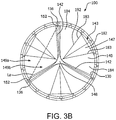
- the attachment angle alpha ( ⁇ ) of a given valve configuration is preserved as the leaflet height is reduced. This is accomplished by redefining the base of the leaflet not as an attachment point 3 as for the generally parabolic leaflet shape as shown in FIG. 1A , but as an attachment line 147 as shown in FIGs. 3B and 15 , that is parallel to the horizontal line in the valve cross sectional plane perpendicular to the valve axis X at the leaflet base 143 of the leaflet 140.
- the first horizontal line L1 extends through the leaflet base 3 as it moves perpendicular along the valve axis X towards the commissure tops 4.
- a plane containing the first horizontal line L1 and perpendicular to the valve axis referred to as the alpha plane, intersects the leaflet frame 130 of FIG. 1A along a line.
- the leaflet base 3 is truncated by the alpha plane, wherein the attachment point 7 of the leaflet base 3 becomes an attachment line 147, that is, a line of attachment rather than a point, of the leaflet base 143 as shown in FIG. 1A , 3B and 15 .
- an apex line La is indicated connecting the apices 152 of the leaflets 140.
- the apex line La divides the leaflet 140 into a first region 149a adjacent the leaflet frame 130, and a second region 149b adjacent the leaflet free edge.
- the first region 149a defines a truncated zone.
- the truncated zone is located on the lower section of the leaflet 140 adjacent the leaflet base 143.
- the truncation zone is that area of the leaflet 140 that may be truncated by a truncation plane intersecting the alpha plane so as to define an attachment line 147, i.e., a line of attachment, of the leaflet base 143.
- FIG. 1A is a side view of a prosthetic heart valve 100, in accordance with an embodiment.
- FIG 1B is also a side view of the prosthetic heart valve 100 of FIG. 1A rotated 60 degrees about the longitudinal axis X.
- FIG. 1C is a perspective view of the prosthetic heart valve 100 of FIG. 1A .
- FIG. 2A is a side view of the prosthetic heart valve 100 of FIG. 1A wherein the prosthetic heart valve 100 has been longitudinally cut and laid open to better illustrate the elements of the generally tubular-shaped prosthetic heart valve 100.
- FIG. 2B is an exploded view of the embodiment of FIG. 2A .
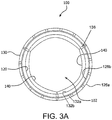
- FIGs. 3A and 3B are axial views of the prosthetic heart valve 100 of FIG. 1A in an open and closed configuration, respectively.
- FIG. 1A is a side view of a prosthetic heart valve 100, in accordance with an embodiment.
- FIG 1B is also a side view of the prosthetic heart valve 100 of FIG. 1A rotated 60 degrees about
- the leaflets 140 are shown slightly open to better show the features but it is understood that a fully closed prosthetic heart valve 100 will have the leaflet free edges 142 of the leaflets 140 coming together to coapt under the influence of downstream fluid pressure which results in closing the valve to prevent downstream blood from flowing retrograde through the valve.
- the prosthetic heart valve 100 comprises an outer frame 120, a leaflet frame 130, and a film 160 covering the outer frame 120 and leaflet frame 130, coupling the outer frame 120 to the leaflet frame 130, and defining leaflets 140.
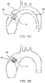
- the embodiment of prosthetic heart valve 100 is discussed further related to a transcatheter valve that may be compressed and re-expanded. It is understood that the embodiment of prosthetic heart valve 100 is also applicable to a surgical valve by the addition of a sewing cuff 170 as shown in FIG. 4B .
- Leaflet frame and outer frame configurations related to surgical valve only embodiments where the valves have a fixed diameter, will be discussed in other embodiments later in this disclosure.
- a prosthetic valve comprises a leaflet frame 130 having a generally tubular shape, an outer frame 120 having a generally tubular shape, and film 160.
- the leaflet frame 130 is coaxially disposed at least partially within the outer frame 120.
- the outer frame 120 provides frame elements that overlay leaflet windows that are defined by the leaflet frame 130 so as to provide structural support over the leaflet windows, as shown in FIGs. 1A-1B .
- the leaflet frame 130 defines a plurality of leaflet windows, wherein the film 160 defines a leaflet extending from each of the leaflet windows.
- FIG. 11A is a side view of a prosthetic heart valve 200, in accordance with an embodiment.
- FIG. 11B is a perspective view of the prosthetic heart valve 200 of FIG. 1A .
- the prosthetic heart valve 200 comprises a leaflet frame 130f and film 160 that defines leaflets 140.
- the leaflets 140 are shown slightly open to better show the features but it is understood that a fully closed prosthetic heart valve 200 will have the leaflet free edges 142 of the leaflets 140 coming together to coapt under the influence of downstream fluid pressure which results in closing the valve to prevent downstream blood from flowing retrograde through the valve.
- frame element refers to any portion of the leaflet frame 130, such as, but not limited to, those individual portions that define a leaflet window 137.
- the leaflet frame first end 131a further comprises commissure posts 136 extending from an apex of the leaflet frame elements defining substantially a triangle.
- FIG. 8D is a side view of the leaflet frame 130f of the prosthetic heart valve 200 of FIG. 11A and 11B wherein the leaflet frame 130f has been longitudinally cut and laid open to better illustrate the elements of the generally tubular-shaped prosthetic heart valve 200.
- the leaflet frame 130f comprises a plurality of spaced apart frame elements 139 defining substantially an isosceles triangles interconnected by a base element 138f defining leaflet windows 137f having the shape of and isosceles trapezoid.
- Each leaflet window side 133 is defined by a side of one triangle and a side of an adjacent triangle, and wherein each leaflet window base 134 is defined by the base element 138.
- the term "frame element" as used herein refers to any portion of the leaflet frame 130, such as, but not limited to, those individual portions that define a leaflet window 137.
- the leaflet frame first end 131a further comprises commissure posts 136 extending from an apex of the leaflet frame elements defining substantially an isosceles triangle.
- the commissure post 136 may affect the leaflet free edge 142 so as to create a larger or wider coaptation region 146 between adjacent leaflet free edges 142.
- the outer frame 120 is a generally tubular member defining a generally open pattern of apertures 122, in accordance with an embodiment, as shown in FIG. 1C .
- the outer frame 120 is operable to allow it to be compressed and expanded between different diameters.
- the outer frame 120 comprises an outer frame outer surface 126a and an outer frame inner surface 126b opposite the outer frame outer surface 126a, as shown in FIG. 5A .
- the outer frame 120 may comprise a structure known in the art as a stent.
- a stent is a tubular member that may have a small diameter suitable for percutaneous transcatheter delivery into the anatomy, and may be expanded to a larger diameter when deployed into the anatomy. Stents having various designs and material properties are well known in the art.
- the prosthetic heart valve 100 includes the outer frame 120 that defines a stent having apertures 122 having generally a diamond shape when in a large diameter configuration, as shown generally in FIG. 1D .
- the apertures 122 Upon compression to a smaller diameter, the apertures 122 deform to generally define an elongated diamond shape, as shown generally in FIG. 1E .
- the apertures 122 Upon re-expansion to a larger diameter, the apertures 122 re-expand to again define a generally diamond shape.
- the leaflet frame 130 has a generally tubular shape defining a plurality of leaflet windows (not shown).
- the outer frame 120 has a generally tubular shape.
- the leaflet frame 130 is coaxially disposed at least partially within the outer frame 120.
- the leaflet frame 130 and outer frame 120 are coupled at least in part by a contiguous portion of the film 160. At least a portion of the contiguous portion of the film 160 is contained between and couples the leaflet frame 130 to the outer frame 120 to inhibit relative movement therebetween.
- the film defines a leaflet 140 extending from each of the leaflet windows.
- the leaflet base 143 is defined at a fold line 145 in the film 160. In accordance with an embodiment, at least a portion of the contiguous portion of the film 160 that is contained between and coupling the leaflet frame 130 and outer frame 120 prevents contact between the leaflet frame 130 and outer frame 120.
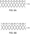
- FIGs. 6A and 6B are side views of alternative embodiments of the outer frame 120a, 120b wherein the outer frame has been longitudinally cut and laid open to better illustrate the elements of the outer frame
- An open framework of the stent can define any number of features, repeatable or otherwise, such as geometric shapes and/or linear or meandering series of sinusoids. Geometric shapes can comprise any shape that facilitates substantially uniform circumferential compression and expansion.
- the outer frame 120 may comprise a cut tube, or any other element suitable for the particular purpose. The outer frame 120 may be etched, cut, laser cut, or stamped into a tube or a sheet of material, with the sheet then formed into a substantially cylindrical structure.
- an elongated material such as a wire, bendable strip, or a series thereof, can be bent or braided and formed into a substantially cylindrical structure wherein the walls of the cylinder comprise an open framework that is compressible to a smaller diameter in a generally uniform and circumferential manner and expandable to a larger diameter.
- stents of various designs may be elastically deformable so as to be self-expanding under spring loads. It is also known that stents of various designs may be plastically deformable so as to be mechanically expanded such as with a balloon. It is also known that stents of various designs may be plastically deformable as well as elastically deformable.
- the embodiments of the outer frame 120 presented herein are not to be limited to a specific stent design or mode of expansion.
- the outer frame 120 can comprise any metallic or polymeric biocompatible material.
- the outer frame 120 can comprise a material, such as, but not limited to nitinol, cobalt-nickel alloy, stainless steel, or polypropylene, acetyl homopolymer, acetyl copolymer, ePTFE, other alloys or polymers, or any other biocompatible material having adequate physical and mechanical properties to function as described herein.
- the outer frame 120 and/or leaflet frame 130 can be configured to provide positive engagement with an implant site to firmly anchor the prosthetic heart valve 100 to the site, as shown in FIG. 4A representing a transcatheter deployment of the prosthetic heart valve 100.
- the outer frame 120 can comprise a sufficiently rigid frame having small elastic recoil so as to maintain sufficient apposition against a tissue orifice 150 to maintain position.
- the outer frame 120 and/or leaflet frame 130 can be configured to expand to a diameter that is larger than a tissue orifice 150 so that when prosthetic heart valve 100 expands into the tissue orifice 150, it can be firmly seated therein.
- the outer frame 120 can comprise one or more anchors (not shown) configured to engage the implant site, such as a tissue orifice 150, to secure the prosthetic heart valve 100 to the implant site.
- the surgical prosthetic heart valve 100 embodiment may or may not have the zigzag configuration since the surgical prosthetic heart valve 100 may be of a fixed diameter and need not be operable to compress and re-expand.
- the prosthetic heart valve 100 further comprises a sewing cuff 190 about an outer frame outer surface 126a in accordance with an embodiment, as shown in FIG. 4B .
- the sewing cuff 190 is operable to provide structure that receives suture for coupling to the implant site.
- the sewing cuff 190 may comprise any suitable material, such as, but not limited to, double velour polyester.
- the sewing cuff 190 may be located circumferentially around a perimeter of the outer frame 120. Sewing cuffs are known in the art.
- the leaflet frame 130 is a generally tubular member defining a plurality of leaflet windows 137 coupled together by connecting frame elements 139, in accordance with an embodiment.
- the leaflet frame 130 comprises a leaflet frame first end 131a and a leaflet frame second end 131b opposite the leaflet frame first end 1381.
- the leaflet frame 130 comprises a leaflet frame outer surface 132a and a leaflet frame inner surface 132b opposite the leaflet frame outer surface 132a, as shown in FIG. 5A .
- the leaflet frame first end 131a and the leaflet frame second end 131b define a generally zigzag configuration to facilitate flexion about flex points 179 such as which facilitates compression and expansion between different diameters for compression onto a delivery device and expansion by a balloon for the transcatheter prosthetic heart valve 100 embodiments, as generally explained for the outer frame 120.
- the surgical prosthetic heart valve 100 embodiment may or may not have the zigzag configuration since the surgical prosthetic heart valve 100 may be of a fixed diameter and need not be operable to compress and re-expand.
- the leaflet frame 130 may be referred to in a general sense as a stent or a frame.
- the leaflet frame 130 defines a predetermined repeating pattern as shown in FIG. 2B , in accordance with an embodiment.
- the leaflet frame 130 defines three interconnected leaflet windows 137 having a substantially triangular shape.
- Each of the leaflet windows 137 include two leaflet window sides 133, a leaflet window base 134, and a leaflet window top 135.
- the leaflet window base 134 defines a flex point 179 which will be described further below.
- a leaflet window side 133 and leaflet window top 135 of one leaflet window 137 is interconnected with a leaflet window side 133 of an adjacent leaflet window 137.
- the leaflet frame 130 defines any number of features and geometric shapes that facilitate substantially uniform circumferential compression and expansion.
- the leaflet frame 130 may comprise a cut tube, or any other element suitable for the particular purpose.
- the leaflet frame 130 may be etched, cut, laser cut, or stamped into a tube or a sheet of material, with the sheet then formed into a substantially cylindrical structure.
- an elongated material such as a wire, bendable strip, or a series thereof, can be bent or braided and formed into a substantially cylindrical structure wherein the walls of the cylinder comprise an open framework that is compressible to a smaller diameter in a generally uniform and circumferential manner and expandable to a larger diameter.
- the leaflet frame 130 can comprise any metallic or polymeric biocompatible material.
- the leaflet frame 130 can comprise a material, such as, but not limited to nitinol, cobalt-nickel alloy, stainless steel, or polypropylene, acetyl homopolymer, acetyl copolymer, ePTFE, other alloys or polymers, or any other biocompatible material having adequate physical and mechanical properties to function as described herein.
- a film 160 is disposed over each of the three leaflet windows 137 to form a leaflet 140.
- the leaflet window 137 defines shapes other than a substantially triangular shape, including, but not limited to a parabolic shape and a trapezoidal shape, with and without a leaflet window top 135, suitable for a particular purpose of an embodiment of a surgical and transcatheter prosthetic heart valve 100.
- FIGs. 7A and 7B are side views of alternative embodiments of the leaflet frame 130a, 130b wherein the leaflet frame has been longitudinally cut and laid open to better illustrate the elements of the leaflet frame.
- the leaflet frame 130a includes leaflet windows 137a having a substantially triangular shape defining a pointed leaflet window base 134a.
- the leaflet frame 130b includes leaflet windows 137b having a substantially triangular shape defining a flat leaflet window base 134b.
- the flat leaflet window base 134b may be used to define the leaflet base 143.
- the leaflet frame 130a is comprised of a generally cylindrical arrangement of three triangular-shaped leaflet windows 137a, the centers of which are each spaced apart by 120°.
- the embodiment of the leaflet frame 130a of FIG. 7A is substantially the same as the embodiment of the leaflet frame 130 as shown in FIG. 2B .
- the leaflet frame 130 as shown in FIG. 2B has a leaflet frame first end 131a and a leaflet frame second end 131b opposite from the leaflet frame first end 131a.
- FIGs. 8A-8C are side views of alternative embodiments of the leaflet frame 130c-130e wherein the leaflet frame has been longitudinally cut and laid open to better illustrate the elements of the leaflet frame.
- the leaflet frame 130c includes leaflet windows 137c having a substantially triangular shape defining a pointed leaflet window base 134c.
- the leaflet frame 130d includes leaflet windows 137d having a substantially parabolic shape defining a rounded leaflet window base 134d.
- the flat leaflet window base 134b may be used to define the leaflet base.
- the leaflet frame 130e includes leaflet windows 137e having a substantially triangular shape defining a pointed leaflet window base 134c but not having a leaflet window top.
- FIG. 8D is a side view of an alternative embodiment of the leaflet frame 130f wherein the leaflet frame 130f has been longitudinally cut and laid open to better illustrate the elements of the leaflet frame.
- the leaflet frame 130f includes leaflet windows 137f having a substantially isosceles trapezoid shape defining a flat leaflet window base 134f.
- the flat leaflet window base 134f may be used to define the leaflet base.
- each leaflet 140f has substantially the shape of an isosceles trapezoid having two leaflet sides 141f, a leaflet base 143f and a leaflet free edge 142f opposite the leaflet base 143f, wherein the two leaflet sides 141f diverge from the leaflet base 143f, wherein the leaflet base 143f is substantially flat, as shown in dashed lines in FIG. 8D .
- FIG. 8E is a side view of an alternative embodiment of the leaflet frame 130g wherein the leaflet frame 130g has been longitudinally cut and laid open to better illustrate the elements of the leaflet frame.
- the leaflet frame 130g includes leaflet windows 137g having a substantially isosceles trapezoid shape defining a flat leaflet window base 134f.
- the flat leaflet window base 134g may be used to define the leaflet base.
- each leaflet 140g has substantially the shape of an isosceles trapezoid having two leaflet sides 141g, a leaflet base 143g and a leaflet free edge 142g opposite the leaflet base, wherein the two leaflet sides 141g diverge from the leaflet base 143g, wherein the leaflet base 143g is substantially flat, as shown in dashed lines in FIG. 8E .
- the frame comprises a plurality of spaced apart leaflet windows 137f each leaflet attachment zone defines substantially an isosceles triangle interconnected by a base element 138f, wherein each leaflet window side is defined by a side of one triangle and a side of an adjacent triangle, and wherein each leaflet window base is defined by the base element 138f.
- FIG. 7A is a representation of another embodiment of a leaflet frame 130a unrolled to a flat orientation.
- the leaflet frame 130a comprises frame elements 139 suitable for affecting compression and expansion as would be needed for intravascular placement.
- the leaflet window 137a is defined by two leaflet window sides 133a that meet at a leaflet window base 134a.
- a leaflet 140 is shown in dashed line to represent where the leaflet 140 is located within the leaflet window 137a.
- the leaflet sides 141 are coupled to the leaflet window sides 133a and the leaflet base 143 is coupled to the leaflet window base 134a.
- FIG. 7B is a representation of another embodiment of a leaflet frame 130b unrolled to a flat orientation.
- the leaflet window 137b is defined by two leaflet window sides 133b that meet at a leaflet window base 134b that is elongated and horizontal with the valve axis.
- a leaflet 140 is shown in dashed line to represent where the leaflet 140 is located within the leaflet window 137a.
- the leaflet sides 141 are coupled to the leaflet window sides 133a and the leaflet base 143b is coupled to the leaflet window base 134a.
- the leaflet window base 134b is flat such that the leaflet bends from a flat base during opening and closing.
- FIG. 8A is a representation of another embodiment of a leaflet frame 130c unrolled to a flat orientation.
- the leaflet frame 130c comprises frame elements 139 suitable for affecting compression and expansion as would be needed for intravascular placement.
- the leaflet window 137c is defined by two leaflet window sides 133c that meet at a leaflet window base 134c.
- a leaflet 140 is shown in dashed line to represent where the leaflet 140 is located within the leaflet window 137c.
- the leaflet sides 141 are coupled to the leaflet window sides 133c and the leaflet base 143c is coupled to the leaflet window base 134c.
- FIG. 8B is a representation of another embodiment of a leaflet frame 130d unrolled to a flat orientation.
- the leaflet frame 130d comprises frame elements 139 suitable for affecting compression and expansion as would be needed for intravascular placement.
- the leaflet window 137d is defined by two leaflet window sides 133d that meet at a leaflet window base 134d.
- a leaflet 140 is shown in dashed line to represent where the leaflet 140 is located within the leaflet window 137d.
- the leaflet sides 141 are coupled to the leaflet window sides 133d and the leaflet base 143d is coupled to the leaflet window base 134d.
- the leaflet window sides 133d define a parabolic shape.
- FIG. 8C is a representation of another embodiment of a leaflet frame 130e unrolled to a flat orientation.
- the leaflet frame 130e comprises frame elements 139 suitable for affecting compression and expansion as would be needed for intravascular placement.
- the leaflet window 137e is defined by two leaflet window sides 133e that meet at a leaflet window base 134e.
- a leaflet 140 is shown in dashed line to represent where the leaflet 140 is located within the leaflet window 137e.
- the leaflet sides 141 are coupled to the leaflet window sides 133e and the leaflet base 143e is coupled to the leaflet window base 134a.
- FIG. 8D is a side view of an alternative embodiment of the leaflet frame 130f wherein the leaflet frame 130f has been longitudinally cut and laid open to better illustrate the elements of the leaflet frame 130f, of a valve substantially shown as the prosthetic heart valve 100 of FIGs. 11A and 11B .
- a leaflet 140f is shown in dashed line to represent where the leaflet 140f is located within the leaflet window 137f, the leaflet window 137f being defined by the leaflet window sides 133f and the leaflet window base 134f.
- the two leaflet sides 141f diverge from the leaflet base 143f, wherein the leaflet base 143f is substantially flat, with the leaflet free edge 142f opposite the leaflet base 143f, as shown in dashed lines in FIG. 8D .
- the leaflet frame 130f further defines commissure posts 136 from which the leaflet free edge 142f extends.
- FIG. 8E is a side view of an alternative embodiment of the leaflet frame 130g wherein the leaflet frame 130g has been longitudinally cut and laid open to better illustrate the elements of the leaflet frame 130g.
- a leaflet 140g is shown in dashed line to represent where the leaflet 140g is located within the leaflet window 137g, the leaflet window 137g being defined by the leaflet window sides 133g and the leaflet window base 134g.
- Two leaflet sides 141g diverge from the leaflet base 143g, wherein the leaflet base 143g is substantially flat, with the leaflet free edge 142g opposite the leaflet base 143g, as shown in dashed lines in FIG. 8E .
- the leaflet frame 130g comprises a plurality of leaflet frame elements defining a plurality of isosceles triangles interconnected by a leaflet window base 134g defining leaflet windows 137g that define isosceles trapezoids.
- Each leaflet window side 133g is defined by a side of one triangle and a side of an adjacent triangle.
- FIG. 8F is a side view of an alternative embodiment of the leaflet frame 130h wherein the leaflet frame 130h has been longitudinally cut and laid open to better illustrate the elements of the leaflet frame 130h.
- the leaflet frame 130h comprises a base element 138h and a plurality of spaced apart spade elements 170 interconnected by the base element 138h.
- Each leaflet window 137h is defined by a spade side 175 of one spade element 170 and a spade side 175 of an adjacent spade element 170, and wherein each leaflet window base 134h is defined by the base element 138h.
- the spade side 175 does not extend to the base element 138h.
- the leaflet 140h during opening and closing, will bend about the spade side 175 and towards the base element 138h defining a partially frameless leaflet window 137h where the leaflet 140 is not bending directly adjacent a frame element 139, defining an attachment zone 163.
- the leaflet base 143h may be defined a distance away from the base element 138h such that the leaflet base 143h is not bending directly adjacent the base element 138h.
- a leaflet window base that is not directly adjacent the base element 138h or the leaflet window base 134h is referred herein as a virtual leaflet window base 134v, virtual in the sense that it is not defined directly by a frame element.
- each leaflet 140h takes the form of substantially the shape of an isosceles trapezoid having two leaflet sides 141h, a leaflet base 143h and a leaflet free edge 142h opposite the leaflet base 143h, wherein the two leaflet sides 141h diverge from the leaflet base 143h, wherein the leaflet base 143h is substantially flat, as shown in dashed lines in FIG. 8F .
- the leaflet frame comprises a frame first end and a frame second end opposite the frame first end, the leaflet window having a shape determined, at least in part, by wrapping a two dimensional isosceles trapezoid onto the tubular shape of the frame, the isosceles trapezoid having a base and two sides that diverge from the base, and wherein a side from adjacent isosceles trapezoids meet at the frame second end.
- a first layer of film 160a is coupled to a leaflet frame inner surface 132b of the leaflet frame 130h and a second layer of film 160b is coupled to a leaflet frame outer surface 132a of the leaflet frame 130h opposite from the leaflet frame inner surface 132b.
- the first layer of film 160 and the second layer of film 160b are coupled together to define an attachment zone 163.
- the leaflet window base may be used to define the leaflet base 143 in accordance with embodiments.
- the leaflet base 143 may be defined as a virtual leaflet window base 134v by a fold line 145 in the film 160 in the fold region 144 spaced apart from the leaflet window base 134, as shown in FIGs. 1A , 1B and 2B . It is appreciated that there are many embodiments of the outer frame having configurations suitable for the particular purpose.
- FIG. 10A is a side exploded view of another prosthetic heart valve comprising a leaflet frame 1130 having a generally tubular shape and an outer frame 1120 having a generally tubular shape that are coupled by a mechanical engagement member 1110, in accordance with another embodiment.
- FIG. 10B is an assembled view of the embodiment of FIG. 10A .
- the leaflet window base may be used to define the leaflet base in accordance with embodiments.
- the leaflet base may be defined as a virtual leaflet base 143v by a fold line 145 in the film 160 in the fold region 144 spaced apart from the leaflet window base, as shown in FIG. 1B and 2B . It is appreciated that there are many embodiments of the leaflet frame having configurations suitable for the particular purpose.
- the leaflet frame 130 is elastically, plastically, or both, compressible to obtain a relatively small diameter to accommodate percutaneous transcatheter mounting and delivery.
- the leaflet frame 130 may comprise, such as, but not limited to, any elastically deformable metallic or polymeric biocompatible material, in accordance with embodiments.
- the leaflet frame 130 may comprise a shape-memory material, such as nitinol, a nickel-titanium alloy.
- Other materials suitable for the leaflet frame 130 include, but are not limited to, other titanium alloys, stainless steel, cobalt-nickel alloy, polypropylene, acetyl homopolymer, acetyl copolymer, other alloys or polymers, or any other biocompatible material having adequate physical and mechanical properties to function as a leaflet frame 130 as described herein.
- the leaflet frame 130 and the outer frame 120 comprise a shape memory material operable to flex under load and retain its original shape when the load is removed, thus allowing the leaflet frame 130 and the outer frame 120 to self-expand from a compressed shape to a predetermined shape.
- the leaflet frame 130 and the outer frame 120 may comprise the same or different materials.
- the leaflet frame 130 is plastically deformable to be expanded by a balloon.
- the outer frame 120 is elastically deformable so as to be self-expanding.
- the film 160 is generally any sheet-like material that is biologically compatible and configured to couple to leaflets to the leaflet frame, in accordance with embodiments. It is understood that the term “film” is used generically for one or more biocompatible materials suitable for a particular purpose.
- the leaflets 140 are also comprised of the film 160.
- the film 160 that is not of a biological source and that is sufficiently flexible and strong for the particular purpose, such as a biocompatible polymer.
- the film 160 comprises a biocompatible polymer that is combined with an elastomer, referred to as a composite.
- the film 160 that is coupled to the outer frame 120 may not be the same film 160 that is coupled to the leaflet frame 130, in accordance with embodiments. Details of various types of film 160 are discussed below.
- the film 160 may be formed from a generally tubular material to at least partially cover the outer frame 120 and the leaflet frame 130.
- the film 160 can comprise one or more of a membrane, composite material, or laminate. Details of various types of film 160 are discussed below.
- Each leaflet window 137 is provided with a film 160, which is coupled to a portion of the leaflet window sides 133 with the film 160 defining a leaflet 140.
- Each leaflet 140 defines a leaflet free edge 142 and a leaflet base 143, in accordance with an embodiment. As will be described below, it is anticipated that a plurality of embodiments of leaflet base configurations may be provided.
- the film 160 is coupled to a portion of the leaflet window sides 133 and to the leaflet window base 134 where the leaflet 140 is defined by the portion of the leaflet window sides 133 and to the leaflet window base 134.
- the film 160 is coupled to a portion of the leaflet window sides 133 but not the leaflet window base 134 of the leaflet frame 130 where the leaflet 140 is defined by the portion of the leaflet window sides 133 and to a virtual leaflet base 143v defined in a fold region 144 as will be described below.
- the shape of the leaflets 140 are defined in part by the shape of the leaflet window 137 and the leaflet free edge 142. As will be discussed below in accordance with an embodiment, the shape of the leaflets 140 also depends in part on a process that induces a fold at the fold line 145 to define a virtual leaflet base 143v as will be described further below, so as to impart a predetermined shape to the leaflet 140. Since high bending stresses are located at the leaflet base, defining a virtual leaflet base 143v that is not bound by the leaflet window base 134 may reduce the chance of tearing of the leaflet 140 at the leaflet base 143 - leaflet window base 134 interface. It may also reduce blood pooling and stagnation at the leaflet base as compared with a rounded leaflet base.
- the prosthetic heart valve 100 When the leaflets 140 are in a fully open position, the prosthetic heart valve 100 presents a substantially circular valve orifice 102 as shown in FIG. 3A . Fluid flow is permitted through the valve orifice 102 when the leaflets 140 are in an open position.
- each leaflet free edge 142 abuts an adjacent half of a leaflet free edge 142 of an adjacent leaflet 140, as shown in FIG. 3B .
- the three leaflets 140 of the embodiment of FIG. 3B meet at a triple point 148.
- the valve orifice 102 is occluded when the leaflets 140 are in the closed position stopping fluid flow.
- FIG. 3B is an axial view of an embodiment of a prosthetic heart valve in a closed configuration.
- Each leaflet 140 includes a central region 182 and two side regions 184 on opposite sides of the central region 182.
- the central region 182 is defined by a shape substantially that of an isosceles triangle defined by two central region sides 183, the leaflet base 143 and the leaflet free edge 142.
- the two central region sides 183 converge from the leaflet base 143 to the leaflet free edge 142.
- Each of the side regions 184 have a shape substantially that of a triangle and each are defined by one of the central region sides 183, one of the leaflet sides 141, and the leaflet free edge 142.
- the leaflets 140 are shown slightly open to better show the features but it is understood that a fully closed prosthetic heart valve 100 will have the leaflet free edges 142 of the leaflets 140 coming together to coapt under the influence of downstream fluid pressure which results in closing the valve to prevent downstream blood from flowing retrograde through the valve.
- FIG. 14 is an axial view of an embodiment of a prosthetic heart valve in a closed configuration.
- Each leaflet 140 includes a central region 182 and two side regions 184 on opposite sides of the central region 182.
- the central region 182 is defined by a shape substantially that of an isosceles triangle defined by two central region sides 183, the leaflet base 143 and the leaflet free edge 142.
- the two central region sides 183 converge from the leaflet base 143 to the leaflet free edge 142.
- Each of the side regions 184 have a shape substantially that of a triangle and each are defined by one of the central region sides 183, one of the leaflet sides 141, and the leaflet free edge 142.
- leaflets 140 are shown slightly open to better show the features but it is understood that a fully closed prosthetic heart valve 100 will have the leaflet free edges 142 of the leaflets 140 coming together to coapt under the influence of downstream fluid pressure which results in closing the valve to prevent downstream blood from flowing retrograde through the valve.
- FIG. 15 is an axial view of an embodiment of a prosthetic heart valve in a closed configuration.
- Each leaflet 140 includes a central region 182 and two side regions 184 on opposite sides of the central region 182.
- the central region 182 is defined by a shape substantially that of an isosceles triangle defined by two central region sides 183, the leaflet base 143 and the leaflet free edge 142.
- the two central region sides 183 converge from the leaflet base 143 to the leaflet free edge 142.
- Each of the side regions 184 have a shape substantially that of a triangle and each are defined by one of the central region sides 183, one of the leaflet sides 141, and the leaflet free edge 142.
- the leaflets 140 are shown slightly open to better show the features but it is understood that a fully closed prosthetic heart valve 100 will have the leaflet free edges 142 of the leaflets 140 coming together to coapt under the influence of downstream fluid pressure which results in closing the valve to prevent downstream blood from flowing retrograde through the valve.
- each of the two side regions 184 and the central region 182 are substantially planar when the prosthetic heart valve 100 is in the closed position.
- the leaflet 140 can be configured to actuate at a pressure differential in the blood caused, for example, by the contraction of a ventricle or atrium of the heart, such pressure differential typically resulting from a fluid pressure building up on one side of the prosthetic heart valve 100 when closed.
- a pressure differential in the blood caused, for example, by the contraction of a ventricle or atrium of the heart, such pressure differential typically resulting from a fluid pressure building up on one side of the prosthetic heart valve 100 when closed.
- the leaflet 140 opens and blood flows therethrough.
- the pressure equalizes.
- the leaflet 140 returns to the closed position generally preventing the retrograde flow of blood through the inflow side of the prosthetic heart valve 100.
- leaflet frame 130 may comprise any number of leaflet windows 137, and thus leaflets 140, suitable for a particular purpose, in accordance with embodiments.
- Leaflet frames 130 comprising one, two, three or more leaflet windows 137 and corresponding leaflets 140 are anticipated.
- the prosthetic heart valve 100 may be compressed into a collapsed configuration having a smaller diameter and expanded into an expanded configuration so that the prosthetic heart valve 100 can be delivered via catheter in the collapsed configuration and expanded upon deployment within the tissue orifice 150 as shown in FIG. 4A .
- the outer frame 120 can be operable to recover circumferential uniformity when transitioning from the collapsed configuration to the expanded configuration.
- the film 160 that makes up the leaflet 140 can comprise any biological tissue or synthetic, biocompatible materials sufficiently compliant and flexible, such as a biocompatible polymer.
- the leaflet 140 comprises a biocompatible polymer that is combined with an elastomer, referred to as a composite.
- a material according to one embodiment includes a composite material comprising an expanded fluoropolymer membrane, which comprises a plurality of spaces within a matrix of fibrils, and an elastomeric material. It should be appreciated that multiple types of fluoropolymer membranes and multiple types of elastomeric materials can be combined to form a laminate while remaining within the scope of the present disclosure. It should also be appreciated that the elastomeric material can include multiple elastomers, multiple types of non-elastomeric components, such as inorganic fillers, therapeutic agents, radiopaque markers, and the like while remaining within the scope of the present disclosure.
- the composite material includes an expanded fluoropolymer material made from porous ePTFE membrane, for instance as generally described in U.S. Patent No. 7,306,729 to Bacino .
- the expandable fluoropolymer used to form the expanded fluoropolymer material described, may comprise PTFE homopolymer. In alternative embodiments, blends of PTFE, expandable modified PTFE and/or expanded copolymers of PTFE may be used.
- suitable fluoropolymer materials are described in, for example, U.S. Patent No. 5,708,044, to Branca , U.S. Patent No. 6,541,589, to Baillie , U.S. Patent No. 7,531,611, to Sabol et al. , U.S. Patent Application No. 11/906,877, to Ford , and U.S. Patent Application No. 12/410,050, to Xu et al.
- the expanded fluoropolymer membrane can comprise any suitable microstructure for achieving the desired leaflet performance.
- the expanded fluoropolymer comprises a microstructure of nodes interconnected by fibrils, such as described in U.S. Patent No. 3,953,566 to Gore .
- the fibrils radially extend from the nodes in a plurality of directions, and the membrane has a generally homogeneous structure.
- Membranes having this microstructure may typically exhibit a ratio of matrix tensile strength in two orthogonal directions of less than 2, and possibly less than 1.5.
- the expanded fluoropolymer membrane has a microstructure of substantially only fibrils, as is generally taught by U.S. Patent No. 7,306,729, to Bacino .
- the expanded fluoropolymer membrane having substantially only fibrils can possess a high surface area, such as greater than 20m 2 /g, or greater than 25m 2 /g, and in some embodiments can provide a highly balanced strength material having a product of matrix tensile strengths in two orthogonal directions of at least 1.5 x 10 5 MPa 2 , and/or a ratio of matrix tensile strengths in two orthogonal directions of less than 4, and possibly less than 1.5.
- the expanded fluoropolymer membrane can be tailored to have any suitable thickness and mass to achieve the desired leaflet performance.
- the leaflet 140 comprises an expanded fluoropolymer membrane having a thickness of about 0.1 ⁇ m.
- the expanded fluoropolymer membrane can possess a mass per area of about 1.15 g/m 2 .
- Membranes according to an embodiment of the invention can have matrix tensile strengths of about 411 MPa in the longitudinal direction and 315 MPa in the transverse direction.
- Composite materials described herein can be tailored to have any suitable thickness and mass to achieve the desired leaflet performance.
- Composite materials according to embodiments can include fluoropolymer membranes and have a thickness of about 1.9 ⁇ m and a mass per area of about 4.1 g/m 2 .
- the expanded fluoropolymer membrane combined with elastomer to form a composite material provides the elements of the present disclosure with the performance attributes required for use in high-cycle flexural implant applications, such as prosthetic heart valve leaflets, in various ways.
- the addition of the elastomer can improve the fatigue performance of the leaflet by eliminating or reducing the stiffening observed with ePTFE-only materials.
- the elastomer occupies substantially all of the pore volume or space within the porous structure of the expanded fluoropolymer membrane.
- the elastomer is present in substantially all of the pores of the at least one fluoropolymer layer. Having elastomer filling the pore volume or present in substantially all of the pores reduces the space in which foreign materials can be undesirably incorporated into the composite.
- An example of such foreign material is calcium that may be drawn into the membrane from contact with the blood. If calcium becomes incorporated into the composite material, as used in a prosthetic heart valve leaflet, for example, mechanical damage can occur during cycling open and closed, thus leading to the formation of holes in the leaflet and degradation in hemodynamics.
- the elastomer that is combined with the ePTFE is a thermoplastic copolymer of tetrafluoroethylene (TFE) and perfluoromethyl vinyl ether (PMVE), such as described in U.S. Patent No. 7,462,675 to Chang et al.
- TFE tetrafluoroethylene
- PMVE perfluoromethyl vinyl ether
- the elastomer is combined with the expanded fluoropolymer membrane such that the elastomer occupies substantially all of the void space or pores within the expanded fluoropolymer membrane to form a composite material. This filling of the pores of the expanded fluoropolymer membrane with elastomer can be performed by a variety of methods.
- a method of filling the pores of the expanded fluoropolymer membrane includes the steps of dissolving the elastomer in a solvent suitable to create a solution with a viscosity and surface tension that is appropriate to partially or fully flow into the pores of the expanded fluoropolymer membrane and allow the solvent to evaporate, leaving the filler behind.
- the composite material comprises three layers: two outer layers of ePTFE and an inner layer of a fluoroelastomer disposed therebetween. Additional fluoroelastomers can be suitable and are described in U.S. Publication No. 2004/0024448 to Chang .
- a method of filling the pores of the expanded fluoropolymer membrane includes the steps of delivering the filler via a dispersion to partially or fully fill the pores of the expanded fluoropolymer membrane.
- a method of filling the pores of the expanded fluoropolymer membrane includes the steps of bringing the porous expanded fluoropolymer membrane into contact with a sheet of the elastomer under conditions of heat and/or pressure that allow elastomer to flow into the pores of the expanded fluoropolymer membrane.
- a method of filling the pores of the expanded fluoropolymer membrane includes the steps of polymerizing the elastomer within the pores of the expanded fluoropolymer membrane by first filling the pores with a prepolymer of the elastomer and then at least partially curing the elastomer.
- the leaflets constructed from fluoropolymer materials or ePTFE generally performed better with increasing percentages of elastomer resulting in significantly increased cycle lives.
- the elastomer combined with the ePTFE is a thermoplastic copolymer of tetrafluoroethylene and perfluoromethyl vinyl ether, such as described in U.S. Patent No. 7,462,675 to Chang et al. , and other references that would be known to those of skill in the art.
- biocompatible polymers which can be suitable for use in leaflet 140 include but are not limited to the groups of urethanes, silicones(organopolysiloxanes), copolymers of silicon-urethane, styrene/isobutylene copolymers, polyisobutylene, polyethylene-co-poly(vinyl acetate), polyester copolymers, nylon copolymers, fluorinated hydrocarbon polymers and copolymers or mixtures of each of the foregoing.
- the prosthetic heart valve can be configured to prevent interference with a heart conduction system by not covering a bundle branch in the left ventricle when implanted, such as might be encountered with an aortic valve replacement procedure.
- the prosthetic heart valve can comprise a length of less than about 25 mm or less than about 18 mm.
- the prosthetic heart valve can also comprise an aspect ratio of less than one, wherein the ratio describes the relationship between the length of the prosthetic heart valve to the expanded, functional diameter.
- the prosthetic heart valve can be constructed at any length and, more generally, any desirable dimension.
- the prosthetic heart valve in a collapsed state, can have a collapsed profile that is less than about 35% of the expanded profile.
- the prosthetic heart valve 100 comprising a 26 mm expanded diameter can have a collapsed diameter of less than about 8 mm, or less than about 6 mm.
- the percent difference in diameter is dependent on dimensions and materials of the prosthetic heart valve and its various applications, and therefore, the actual percent difference is not limited by this disclosure.
- the prosthetic heart valve can further comprise a bio-active agent.
- Bio-active agents can be coated onto a portion or the entirety of the film 160 for controlled release of the agents once the prosthetic heart valve is implanted.
- the bio-active agents can include, but are not limited to, vasodilator, anti-coagulants, anti-platelet, anti-thrombogenic agents such as, but not limited to, heparin.
- Other bio-active agents can also include, but are not limited to agents such as, for example, anti-proliferative/antimitotic agents including natural products such as vinca alkaloids (i.e. vinblastine, vincristine, and vinorelbine), paclitaxel, epidipodophyllotoxins (i.e.
- antibiotics dactinomycin (actinomycin D) daunorubicin, doxorubicin and idarubicin
- anthracyclines mitoxantrone, bleomycins, plicamycin (mithramycin) and mitomycin
- enzymes L-asparaginase which systemically metabolizes L-asparagine and deprives cells which do not have the capacity to synthesize their own asparagine
- antiplatelet agents such as G(GP) IIb/IIIa inhibitors and vitronectin receptor antagonists
- anti-proliferative/antimitotic alkylating agents such as nitrogen mustards (mechlorethamine, cyclophosphamide and analogs, melphalan, chlorambucil), ethylenimines and methylmelamines (hexamethylmelamine and thiotepa), alkyl sulfonates-busulfan, nitros
- anti-coagulants heparin, synthetic heparin salts and other inhibitors of thrombin
- fibrinolytic agents such as tissue plasminogen activator, streptokinase and urokinase), aspirin, dipyridamole, ticlopidine, clopidogrel, abciximab
- antimigratory antisecretory (breveldin)
- anti-inflammatory such as adrenocortical steroids (cortisol, cortisone, fludrocortisone, prednisone, prednisolone, 6 ⁇ -methylprednisolone, triamcinolone, betamethasone, and dexamethasone), non-steroidal agents (salicylic acid derivatives i.e.
- a valve delivery system 500 comprises a prosthetic heart valve 100 having a collapsed configuration and an expanded configuration as previously described and an elongated flexible catheter 480, such as a balloon catheter, configured to deploy the prosthetic heart valve 100 via catheter.
- the catheter 480 can comprise a balloon to expand the prosthetic heart valve 100 and/or if required, to touch up the prosthetic heart valve 100 to ensure proper seating.
- the prosthetic heart valve 100 can be mounted to the distal section of the catheter 480 for delivery through the vasculature.
- the valve delivery system may further comprise a removable sheath (not shown) to closely fit over the transcatheter prosthetic heart valve 100.
- a method of delivery can comprise the steps of radially compressing a prosthetic heart valve into its collapsed configuration onto the distal end of an elongate flexible catheter having proximal and distal ends; delivering the prosthetic heart valve to a tissue orifice, such as a native aortic valve orifice, via a transfemoral or transapical route, and expanding the prosthetic heart valve into the tissue orifice.
- the prosthetic heart valve can be expanded by inflating a balloon.
- a method of delivery can comprise the steps of radially compressing a prosthetic heart valve into its collapsed configuration, onto the distal section of an elongated flexible catheter having proximal and distal ends.
- a restraint which can be connected to a tether that passes through the orifice of the prosthetic heart valve and the lumen of the catheter, is fitted around the commissure posts of the prosthetic heart valve.
- the prosthetic heart valve is then delivered to a native valve orifice, such as a native aortic valve orifice, via a route of delivery and expanded into the native orifice.
- the route of delivery can comprise a transfemoral or transapical route.
- the prosthetic heart valve can be expanded by inflating a balloon.
- Embodiments of a surgically implanted prosthetic heart valve 100 may be substantially the same as those described above, with the addition of a sewing cuff 190 adjacent to the outer frame outer surface 126a, shown in FIG. 4B , in accordance with an embodiment.
- the sewing cuff 190 which is well known in the art, is operable to provide structure that receives suture for coupling the prosthetic heart valve 100 to an implant site, such as the tissue orifice 150.
- the sewing cuff 190 may comprise any suitable material, such as, but not limited to, double velour polyester.
- the sewing cuff 190 may be located circumferentially around the outer frame 120.
- Embodiments described herein also pertain to a method of making the prosthetic heart valve 100 embodiments as described herein.
- a cylindrical mandrel 710 can be used.
- the mandrel 710 comprises a structural form operable to receive the outer frame 120 thereon.
- an embodiment of a method of making a prosthetic heart valve 100 comprises the steps of wrapping a first layer of film 160, e.g., a composite as described herein, into a tubular form about the mandrel 710; placing the leaflet frame 130 and outer frame 120 over the first layer of film 160, as shown in FIG.
- Embodiments described herein also pertain to a method of making the prosthetic heart valve 200 embodiments as described herein.
- a cylindrical mandrel 710 can be used.
- the mandrel 710 comprises a structural form operable to receive the leaflet frame 130 thereon.
- An embodiment of a method of making a prosthetic heart valve 200 comprises the steps of wrapping a first layer of film 160, e.g., a composite as described herein, into a tubular form about the mandrel 710; placing the leaflet frame 130 over the first layer of film 160, as shown in FIG.
- FIG. 11A is a side view of an embodiment of a prosthetic heart valve and FIG. 11B is a perspective view of the embodiment of the prosthetic heart valve of FIG. 11A .
- the leaflets 140 are shown slightly open as when held by the cutting mandrel 712. It is understood that a fully closed prosthetic heart valve 200 will have the leaflet free edges 142 of the leaflets 140 coming together to coapt under the influence of downstream fluid pressure which results in closing the valve to prevent downstream blood from flowing retrograde through the valve.
- a prosthetic heart valve was produced having polymeric leaflets formed from a composite material having an expanded fluoropolymer membrane and an elastomeric material and joined between two collapsible metallic frames.
- the leaflet frame and outer frame were laser machined from a length of SS316LVM tube hard tempered with an outside diameter of 23.0 mm and a wall thickness of 0.65 mm in the shape shown illustratively and generally indicated in FIG. 9A .
- the leaflet frame 130 and outer frame 120 were electro-polished resulting in 0.0127 mm material removal from each surface and leaving the edges rounded.
- Fluorinated ethylene propylene (FEP) powder (Daikin America, Orangeburg N.Y.) was then applied to the leaflet frame 130 and outer frame 120. More specifically, the FEP powder was stirred to form an airborne "cloud" in an enclosed blending apparatus, such as a standard kitchen type blender, while the leaflet frame and outer frame were suspended in the cloud. The leaflet frame and outer frame were exposed to the FEP powder cloud until a uniform layer of powder was adhered to the entire surface of the leaflet frame and outer frame. The leaflet frame and outer frame were then subjected to a thermal treatment by placing it in a forced air oven set to 320°C for approximately three minutes. This caused the powder to melt and adhere as a thin coating over the entire leaflet frame and outer frame. The leaflet frame and outer frame were removed from the oven and left to cool to room temperature.
- FEP Fluorinated ethylene propylene
- a 21 mm diameter vented metal cylindrical mandrel having a diameter corresponding to the inner diameter of the leaflet frame 130 and outer frame 120 was helically wrapped with sintered ePTFE fiber.
- a thin film of type 1 (ASTM D3368) FEP was constructed using melt extrusion and stretching.
- the type 1 (ASTM D3368) FEP film was about 40 ⁇ m thick and was about 7.7 cm wide.
- the mandrel was helically wrapped with one layer of this type 1 FEP film over the sintered ePTFE fiber only in the region of outer frame.
- the mandrel was radially wrapped with five layers of an ePTFE membrane with an FEP coating towards the mandrel.
- the ePTFE membrane was manufactured according to the general teachings described in US Patent 7,306,729 .
- the ePTFE membrane had a mass per area of 2.3 g/m 2 , a bubble point of 101.5MPa, a thickness of about 356 nm, a matrix tensile strength of 319 MPa in the longitudinal direction and 407 MPa in the transverse direction.
- the mandrel was helically wrapped with one layer of type 1 FEP film.
- the diameter of the leaflet frame and outer frame were expanded slightly and received on the wrapped mandrel with approximately a 10mm space between them, rotational alignment was not necessary.
- the leaflet frame, outer frame and the space therebetween were helically wrapped with 1 layer of type 1 FEP film.
- leaflet frame, outer frame and the space therebetween that will become the bridge portion 162 and the fold region 144, as shown in FIG. 2B were circumferentially wrapped with 5 layers of the same ePTFE membrane with an FEP coating as described above with the coating toward the mandrel.
- the wrapped leaflet frame, outer frame and the space therebetween were wrapped with several layers of an ePTFE membrane imbibed with a polyimide material referred to as a release liner.
- a substantially nonporous ePTFE membrane was configured into a cylinder and placed over the assembly, referred to as sacrificial tube.
- Sintered ePTFE fiber was used to seal both ends of the sacrificial tube against the mandrel.
- the assembly including the mandrel, was heated in an oven capable of applying pneumatic pressure external to the sacrificial tube described above and while maintaining a vacuum internal to the mandrel for 40 min such that the mandrel temperature reached approximately 360° C.
- the assembly was removed from the oven and allowed to cool to room temperature while still pressurized and under vacuum.
- the sacrificial tube and release liner was removed.
- the sintered ePTFE fiber was removed to release the frame assembly from the mandrel.
- the polymeric material was trimmed and removed from the leaflet windows of the leaflet frame.
- the ends of each leaflet frame and outer frame were circumferentially trimmed by a scalpel.
- An unsintered 15 mm diameter ePTFE tube was disposed on a 21.5 mm vented metal mandrel.
- Two layers of a substantially nonporous ePTFE membrane with a FEP coating was circumferentially wrapped on the mandrel with the coating side towards the mandrel.
- the wrapped mandrel was placed in a convection oven set to 320° C and heated for 20 min.
- the ePTFE and substantially nonporous ePTFE membrane combined to serve as a release liner and was perforated to communicate pressure between the vent holes in the mandrel.
- the leaflet frame was disposed onto the vented metal mandrel and vent holes were made in the apertures of the leaflet frame over the mandrel vent holes.
- a leaflet material was then prepared.
- a membrane of ePTFE was manufactured according to the general teachings described in US Patent 7,306,729 .
- the ePTFE membrane had a mass per area of 0.452 g/m 2 , a thickness of about 508 nm, a matrix tensile strength of 705 MPa in the longitudinal direction and 385 MPa in the transverse direction.
- This membrane was imbibed with a fluoroelastomer.
- the copolymer consists essentially of between about 65 and 70 weight percent perfluoromethyl vinyl ether and complementally about 35 and 30 weight percent tetrafluoroethylene.
- the fluoroelastomer was dissolved in Novec HFE7500 (3M, St Paul, MN) in a 2.5% concentration. The solution was coated using a Mayer bar onto the ePTFE membrane (while being supported by a polypropylene release film) and dried in a convection oven set to 145°C for 30 seconds. After two coating steps, the final ePTFE/fluoroelastomer or composite had a mass per area of 1.75 g/m 2 , 29.3% fluoropolymer by weight, a dome burst strength of about 8.6 KPa, and thickness of 0.81 ⁇ m.
- the following test methods were used to characterize the ePTFE layers and the multi-layered composite.
- the thickness was measured with a Mutitoyo Snap Gage Absolute, 12.7 mm (0.50") diameter foot, Model ID-C112E, Serial # 10299, made in Japan.
- the density was determined by a weight/volume calculation using an Analytical Balance Mettler PM400 New Jersey, USA.
- the composite material is oriented to have a predetermined matrix tensile strength along a direction generally perpendicular with the longitudinal axis of the combined tool assembly. More specifically, the predetermined matrix tensile strength is about 705 MPa.
- the mandrel was radially wrapped with one layer of a substantially nonporous ePTFE membrane with an FEP coating towards the mandrel with a spacing 8 mm from the base of the leaflet frame.
- the ePTFE membrane was manufactured according to the general teachings described in US Patent 7,306,729 .
- the ePTFE membrane had a mass per area of about 11 g/m 2 , a thickness of about 5.5 ⁇ m, a matrix tensile strength of 310 MPa in the longitudinal direction and 103 MPa in the transverse direction.
- a Kapton® (El DuPont de Nemours, Inc., Wilmington, DE) polyimide film acting as a mask was wrapped over the substantially nonporous ePTFE membrane with an FEP coating layer.
- the outer frame was placed on the mandrel with 10 mm spacing between the leaflet frame and the outer frame.
- the leaflet frame and the outer frame were aligned such that the longitudinal outer frame posts were collinear with the leaflet frame commissure posts.
- the leaflet frame and outer frame were wrapped with 24 layers of the composite leaflet material described earlier with an elastomer rich side of the composite facing towards the mandrel.
- the composite material is oriented to have a predetermined matrix tensile strength along a direction generally perpendicular with the longitudinal axis of the combined tool assembly. More specifically, the predetermined matrix tensile strength is about 705 MPa.
- the final leaflet was comprised of 29.3 % fluoropolymer by weight with a thickness of approximately 27 ⁇ m.
- Each leaflet had 34 layers of the composite and a ratio of thickness/number of layers of 0.8 ⁇ m.
- the mandrel was again radially wrapped with one layer of a substantially nonporous ePTFE membrane with an FEP coating towards the mandrel with a spacing 8 mm from the base of the leaflet frame.
- the assembly was wrapped with several layers of the sacrificial release liner.
- a sacrificial tube was placed over the assembly and sintered ePTFE fiber was used to seal both ends of the sacrificial tube against the mandrel.
- the assembly was processed in an oven capable of applying pneumatic pressure external to the sacrificial material configured into a tube described above and while maintaining a vacuum internal to the tube for 25 min such that the mandrel temperature reached approximately 330° C.
- the assembly was removed from the oven and allowed to cool to room temperature while still pressurized and under vacuum.
- the sacrificial tube and liner were removed from the frame assembly and the frame assembly was removed from the mandrel.
- the Kapton® mask was removed.
- a scalpel was used to circumferentially trim the leaflet free edge of each leaflet and the distal end of leaflet frame.
- the outer frame was radially expanded to a 24 mm diameter using a tapered mandrel.
- a release liner as described above was placed on a 21.5mm vented mandrel.
- leaflet frame and outer frame with leaflet material were placed onto the mandrel and the tapered extensions of the Kapton® masks were inserted under the top ring of the leaflet frame from the trimmed end and were advanced axially until the masks aligned with the leaflet window.
- the leaflet frame was wrapped with 2 layers of the type 1 FEP film.
- a hot iron was used to remove the FEP film from the leaflet window region by melting it away from the perimeter and to tack the FEP film in all regions of leaflet frame outside the masks.
- Vent holes were made within all the leaflet frame apertures and in the polymer tube region connecting the inner frame and outer frame.
- the outer frame was coaxially disposed over the leaflet frame by telescopically inverting the bridge portion of the contiguous tube.
- the entire frame assembly was circumferentially wrapped with one substantially nonporous ePTFE membrane with an FEP coating towards the mandrel.
- the assembly was wrapped with several layers of the sacrificial release liner.
- a sacrificial tube was placed over the assembly and sintered ePTFE fiber was used to seal both ends of the sacrificial tube against the mandrel.
- the assembly was processed in an oven capable of applying pneumatic pressure external to the sacrificial material configured into a tube described above and while maintaining a vacuum internal to the tube for 25 min such that the mandrel temperature reached approximately 330° C.
- the assembly was removed from the oven and allowed to cool to room temperature while still pressurized and under vacuum.
- the frame assembly was removed from the mandrel.
- a scalpel was used to circumferentially trim each end of leaflet frame.
- the Kapton was rotationally peeled away from inside the outer frame and away from leaflets.
- both ends of the leaflet frame were trimmed to follow frame contour.
- the resulting prosthetic heart valve 100 includes leaflets 140 formed from a composite material with more than one fluoropolymer layer having a plurality of pores and an elastomer present in substantially all of the pores of the more than one fluoropolymer layer.
- Each leaflet 140 is movable between a closed position, shown in FIGs. 3B , in which blood is substantially prevented from flowing through the valve assembly, and an open position, shown in FIG. 3A , in which blood is allowed to flow through the valve assembly.
- the leaflets 140 of the prosthetic heart valve 100 cycle between the closed and open positions generally to regulate blood flow direction in a human patient.
- the performance of the prosthetic heart valve leaflets was characterized on a real-time pulse duplicator that measured typical anatomical pressures and flows across the prosthetic heart valve.
- the flow performance was characterized by the following process:
- valve assembly was potted into a silicone annular ring (support structure) to allow the valve assembly to be subsequently evaluated in a real-time pulse duplicator.
- the potting process was performed according to the recommendations of the pulse duplicator manufacturer (ViVitro Laboratories Inc., Victoria BC, Canada).
- the potted valve assembly was then placed into a real-time left heart flow pulse duplicator system.
- the flow pulse duplicator system included the following components supplied by VSI Vivitro Systems Inc., Victoria BC, Canada: a Super Pump, Servo Power Amplifier Part Number SPA 3891; a Super Pump Head, Part Number SPH 5891B, 38.320 cm 2 cylinder area; a valve station/fixture; a Wave Form Generator, TriPack Part Number TP 2001; a Sensor Interface, Part Number VB 2004; a Sensor Amplifier Component, Part Number AM 9991; and a Square Wave Electro Magnetic Flow Meter, Carolina Medical Electronics Inc., East Bend, NC, USA.
- the flow pulse duplicator system uses a fixed displacement, piston pump to produce a desired fluid flow through the prosthetic heart valve under test.
- the heart flow pulse duplicator system was adjusted to produce the desired flow (5L/min), mean pressure (15mmHg), and simulated pulse rate (70 bpm). The prosthetic heart valve under test was then cycled for about 5 to 20 minutes.
- Pressure and flow data were measured and collected during the test period, including right ventricular pressures, pulmonary pressures, flow rates, and pump piston position.
- EOA effective orifice area
- ⁇ P mean systolic/diastolic pressure drop
- regurgitant fraction is the amount of fluid or blood regurgitated through the prosthetic heart valve divided by the stroke volume.
- the diameter of the leaflet frame and outer frame were expanded slightly and received on the wrapped mandrel with 16mm space between them, rotational alignment of the leaflet frame and outer frame was made.
- a scalpel was used to cut above the mechanical linking tab. The tab was deformed to link the leaflet frame to the outer frame.
- the resulting prosthetic heart valve 100 includes leaflets 140 formed from a composite material with more than one fluoropolymer layer having a plurality of pores and an elastomer present in substantially all of the pores of the more than one fluoropolymer layer.
- Each leaflet 140 is movable between a closed position, shown in FIG. 3B , in which blood is substantially prevented from flowing through the valve assembly, and an open position, shown in FIG. 3A , in which blood is allowed to flow through the valve assembly.
- the leaflets 140 of the prosthetic heart valve 100 cycle between the closed and open positions generally to regulate blood flow direction in a human patient.
- a prosthetic heart valve having polymeric leaflets formed from a composite material having an expanded fluoropolymer membrane and an elastomeric material and joined to a semi-rigid, non-collapsible metallic frame, and further a having strain relief was constructed according to the following process:
- a leaflet frame was laser machined from a length of MP35N cobalt chromium tube hard tempered with an outside diameter of 26.0 mm and a wall thickness of 0.6 mm in the shape.
- the leaflet frame was electro-polished resulting in 0.0127 mm material removal from each surface and leaving the edges rounded.
- the leaflet frame was exposed to a surface roughening step to improve adherence of leaflets to the leaflet frame.
- the leaflet frame was cleaned by submersion in an ultrasonic bath of acetone for approximately five minutes.
- the entire metal leaflet frame surface was then subjected to a plasma treatment using equipment (e.g. PVA TePLa America, Inc Plasma Pen, Corona, CA) and methods commonly known to those having ordinary skill in the art. This treatment also served to improve the wetting of the fluorinated ethylene propylene (FEP) adhesive.
- FEP fluorinated ethylene propylene
- FEP powder (Daikin America, Orangeburg N.Y.) was then applied to the leaflet frame. More specifically, the FEP powder was stirred to form an airborne "cloud" in an enclosed blending apparatus, such as a standard kitchen type blender, while the leaflet frame is suspended in the cloud. The leaflet frame was exposed to the FEP powder cloud until a layer of powder was adhered to the entire surface of the leaflet frame. The leaflet frame was then subjected to a thermal treatment by placing it in a forced air oven set to 320°C for approximately three minutes. This caused the powder to melt and adhere as a thin coating over the entire leaflet frame. The leaflet frame was removed from the oven and left to cool to approximately room temperature.
- the strain relief was attached to the leaflet frame in the following manner.
- a thin (122 ⁇ m) walled sintered 15 mm diameter ePTFE tube was disposed on a 24.5 mm vented metal mandrel by stretching radially over a tapered mandrel.
- Two layers of a substantially nonporous ePTFE membrane with a continuous FEP coating was circumferentially wrapped on the mandrel with the FEP side towards the mandrel.
- the wrapped mandrel was placed in a convection oven set to 320° C and heated for 20 min.
- the ePTFE and substantially nonporous ePTFE membrane combined to serve as an inner release liner and was perforated using a scalpel blade to communicate pressure between the vent holes in the mandrel. This entire release liner is removed in a later step.
- a 5 cm length of the thick (990 ⁇ ) walled partially sintered 22 mm inner diameter ePTFE tube (density 0.3 g/cm 3 ) was disposed onto the 24.5 mm vented metal mandrel with release liner.
- the ePTFE tube inner diameter was enlarged by stretching it on a tapered mandrel to accommodate the larger mandrel diameter.
- a thin (4 ⁇ m) film of type 1 FEP (ASTM D3368) was constructed using melt extrusion and stretching. One layer of the FEP was wrapped over the 5 cm length of the ePTFE tube.
- the FEP powder coated leaflet frame was disposed onto the vented metal mandrel generally in the middle of the 5 cm span of ePTFE tube and FEP film.
- One layer of the FEP was wrapped over the leaflet frame and 5 cm length of the ePTFE tube.
- a second 5 cm length of the 990 ⁇ m thick / 22 mm inner diameter ePTFE tube was disposed onto the assembly layered onto 24.5 mm vented metal mandrel by stretching its radius over a tapered mandrel to accommodate the larger construct diameter.
- a substantially nonporous ePTFE membrane was configured into a cylinder at a diameter larger than the construct and placed over the assembly, referred to as sacrificial tube.
- Sintered ePTFE fiber e.g. Gore Rastex® Sewing Thread, Part #S024T2, Newark DE
- the assembly including the mandrel, was heated in a convection oven (temperature set point of 390° C) capable of applying pneumatic pressure of 6,89 bar (100 psi) external to the sacrificial tube described above while maintaining a vacuum internal to the mandrel.
- the assembly was cooked for 40 min such that the mandrel temperature reached approximately 360° C (as measured by a thermocouple direct contact with the inner diameter of the mandrel).
- the assembly was removed from the oven and allowed to cool to approximately room temperature while still under 6,89 bar (100 psi) pressure and vacuum.
- the sacrificial tube was then removed. Approximately 2,07 bar (30 psi) of pressure was applied to the internal diameter of the mandrel to assist in removal of the assembly.
- the inner release liner was peeled away from the internal diameter of the assembly by inverting the liner and axially pulling it apart.
- the polymeric material was trimmed with a scalpel and removed from the leaflet windows and bottom of the leaflet frame leaving approximately 0.5 to 1.0 mm of material overhang.
- a leaflet material was then prepared.
- a membrane of ePTFE was manufactured according to the general teachings described in US Patent 7,306,729 .
- the ePTFE membrane had a mass per area of 0.452 g/m 2 , a thickness of about 508 nm, a matrix tensile strength of 705 MPa in the longitudinal direction and 385 MPa in the transverse direction.
- This membrane was imbibed with a fluoroelastomer.
- the copolymer consists essentially of between about 65 and 70 weight percent perfluoromethyl vinyl ether and complementally about 35 and 30 weight percent tetrafluoroethylene.
- the fluoroelastomer was dissolved in Novec HFE7500 (3M, St Paul, MN) in a 2.5% concentration. The solution was coated using a mayer bar onto the ePTFE membrane (while being supported by a polypropylene release film) and dried in a convection oven set to 145°C for 30 seconds. After 2 coating steps, the final ePTFE/fluoroelastomer or composite had a mass per area of 1.75 g/m 2 , 29.3% fluoropolymer by weight, a dome burst strength of about 8.6 KPa, and thickness of 0.81 ⁇ m.
- the final leaflet was comprised of 28.22 % fluoropolymer by weight with a thickness of 50.3 ⁇ m. Each leaflet had 26 layers of the composite and a ratio of thickness/number of layers of 1.93 ⁇ m.
- the resulting prosthetic heart valve 200 includes leaflets 140 formed from a composite material with more than one fluoropolymer layer having a plurality of pores and an elastomer present in substantially all of the pores of the more than one fluoropolymer layer.
- Each leaflet 140 is movable between a closed position, shown illustratively in FIGs. 11D , in which blood is substantially prevented from flowing through the valve assembly, and an open position, shown illustratively in FIG. 11C , in which blood is allowed to flow through the prosthetic heart valve 200.
- the leaflets 140 of the prosthetic heart valve 200 cycle between the closed and open positions generally to regulate blood flow direction in a human patient.
Landscapes
- Health & Medical Sciences (AREA)
- Engineering & Computer Science (AREA)
- Biomedical Technology (AREA)
- Cardiology (AREA)
- Oral & Maxillofacial Surgery (AREA)
- Transplantation (AREA)
- Heart & Thoracic Surgery (AREA)
- Vascular Medicine (AREA)
- Life Sciences & Earth Sciences (AREA)
- Animal Behavior & Ethology (AREA)
- General Health & Medical Sciences (AREA)
- Public Health (AREA)
- Veterinary Medicine (AREA)
- Manufacturing & Machinery (AREA)
- Prostheses (AREA)
Priority Applications (3)
| Application Number | Priority Date | Filing Date | Title |
|---|---|---|---|
| EP17194473.9A EP3298988B1 (en) | 2012-12-19 | 2013-12-19 | Prosthetic vavles, frames and leaflets and methods thereof |
| EP25162398.9A EP4541319A3 (en) | 2012-12-19 | 2013-12-19 | Prosthetic valves, frames and leaflets and methods thereof |
| EP22177518.2A EP4082483A1 (en) | 2012-12-19 | 2013-12-19 | Prosthetic valves, frames and leaflets and methods thereof |
Applications Claiming Priority (4)
| Application Number | Priority Date | Filing Date | Title |
|---|---|---|---|
| US201261739721P | 2012-12-19 | 2012-12-19 | |
| US201361802116P | 2013-03-15 | 2013-03-15 | |
| US14/133,563 US9737398B2 (en) | 2012-12-19 | 2013-12-18 | Prosthetic valves, frames and leaflets and methods thereof |
| PCT/US2013/076688 WO2014100476A1 (en) | 2012-12-19 | 2013-12-19 | Prosthetic valves, frames and leaflets and methods thereof |
Related Child Applications (4)
| Application Number | Title | Priority Date | Filing Date |
|---|---|---|---|
| EP25162398.9A Division EP4541319A3 (en) | 2012-12-19 | 2013-12-19 | Prosthetic valves, frames and leaflets and methods thereof |
| EP22177518.2A Division EP4082483A1 (en) | 2012-12-19 | 2013-12-19 | Prosthetic valves, frames and leaflets and methods thereof |
| EP17194473.9A Division EP3298988B1 (en) | 2012-12-19 | 2013-12-19 | Prosthetic vavles, frames and leaflets and methods thereof |
| EP17194473.9A Division-Into EP3298988B1 (en) | 2012-12-19 | 2013-12-19 | Prosthetic vavles, frames and leaflets and methods thereof |
Publications (2)
| Publication Number | Publication Date |
|---|---|
| EP2934392A1 EP2934392A1 (en) | 2015-10-28 |
| EP2934392B1 true EP2934392B1 (en) | 2018-02-07 |
Family
ID=50975548
Family Applications (4)
| Application Number | Title | Priority Date | Filing Date |
|---|---|---|---|
| EP13824700.2A Active EP2934392B1 (en) | 2012-12-19 | 2013-12-19 | Prosthetic valves, frames and leaflets |
| EP22177518.2A Pending EP4082483A1 (en) | 2012-12-19 | 2013-12-19 | Prosthetic valves, frames and leaflets and methods thereof |
| EP17194473.9A Active EP3298988B1 (en) | 2012-12-19 | 2013-12-19 | Prosthetic vavles, frames and leaflets and methods thereof |
| EP25162398.9A Pending EP4541319A3 (en) | 2012-12-19 | 2013-12-19 | Prosthetic valves, frames and leaflets and methods thereof |
Family Applications After (3)
| Application Number | Title | Priority Date | Filing Date |
|---|---|---|---|
| EP22177518.2A Pending EP4082483A1 (en) | 2012-12-19 | 2013-12-19 | Prosthetic valves, frames and leaflets and methods thereof |
| EP17194473.9A Active EP3298988B1 (en) | 2012-12-19 | 2013-12-19 | Prosthetic vavles, frames and leaflets and methods thereof |
| EP25162398.9A Pending EP4541319A3 (en) | 2012-12-19 | 2013-12-19 | Prosthetic valves, frames and leaflets and methods thereof |
Country Status (10)
Cited By (16)
| Publication number | Priority date | Publication date | Assignee | Title |
|---|---|---|---|---|
| US10856984B2 (en) | 2017-08-25 | 2020-12-08 | Neovasc Tiara Inc. | Sequentially deployed transcatheter mitral valve prosthesis |
| US10940001B2 (en) | 2012-05-30 | 2021-03-09 | Neovasc Tiara Inc. | Methods and apparatus for loading a prosthesis onto a delivery system |
| US11311376B2 (en) | 2019-06-20 | 2022-04-26 | Neovase Tiara Inc. | Low profile prosthetic mitral valve |
| US11357622B2 (en) | 2016-01-29 | 2022-06-14 | Neovase Tiara Inc. | Prosthetic valve for avoiding obstruction of outflow |
| US11389291B2 (en) | 2013-04-04 | 2022-07-19 | Neovase Tiara Inc. | Methods and apparatus for delivering a prosthetic valve to a beating heart |
| US11413139B2 (en) | 2011-11-23 | 2022-08-16 | Neovasc Tiara Inc. | Sequentially deployed transcatheter mitral valve prosthesis |
| US11419720B2 (en) | 2010-05-05 | 2022-08-23 | Neovasc Tiara Inc. | Transcatheter mitral valve prosthesis |
| US11464631B2 (en) | 2016-11-21 | 2022-10-11 | Neovasc Tiara Inc. | Methods and systems for rapid retraction of a transcatheter heart valve delivery system |
| US11491006B2 (en) | 2019-04-10 | 2022-11-08 | Neovasc Tiara Inc. | Prosthetic valve with natural blood flow |
| US11497602B2 (en) | 2012-02-14 | 2022-11-15 | Neovasc Tiara Inc. | Methods and apparatus for engaging a valve prosthesis with tissue |
| US11602429B2 (en) | 2019-04-01 | 2023-03-14 | Neovasc Tiara Inc. | Controllably deployable prosthetic valve |
| US11684474B2 (en) | 2018-01-25 | 2023-06-27 | Edwards Lifesciences Corporation | Delivery system for aided replacement valve recapture and repositioning post-deployment |
| US11737872B2 (en) | 2018-11-08 | 2023-08-29 | Neovasc Tiara Inc. | Ventricular deployment of a transcatheter mitral valve prosthesis |
| US11779742B2 (en) | 2019-05-20 | 2023-10-10 | Neovasc Tiara Inc. | Introducer with hemostasis mechanism |
| US11998447B2 (en) | 2019-03-08 | 2024-06-04 | Neovasc Tiara Inc. | Retrievable prosthesis delivery system |
| US12109111B2 (en) | 2015-12-15 | 2024-10-08 | Neovasc Tiara Inc. | Transseptal delivery system |
Families Citing this family (75)
| Publication number | Priority date | Publication date | Assignee | Title |
|---|---|---|---|---|
| US8945212B2 (en) | 2011-04-01 | 2015-02-03 | W. L. Gore & Associates, Inc. | Durable multi-layer high strength polymer composite suitable for implant and articles produced therefrom |
| US9801712B2 (en) | 2011-04-01 | 2017-10-31 | W. L. Gore & Associates, Inc. | Coherent single layer high strength synthetic polymer composites for prosthetic valves |
| US20130197631A1 (en) | 2011-04-01 | 2013-08-01 | W. L. Gore & Associates, Inc. | Durable multi-layer high strength polymer composite suitable for implant and articles produced therefrom |
| US20140163673A1 (en) * | 2011-04-01 | 2014-06-12 | W. L. Gore & Associates, Inc. | Prosthetic heart valve leaflet adapted for external imaging |
| US9744033B2 (en) | 2011-04-01 | 2017-08-29 | W.L. Gore & Associates, Inc. | Elastomeric leaflet for prosthetic heart valves |
| US8961599B2 (en) | 2011-04-01 | 2015-02-24 | W. L. Gore & Associates, Inc. | Durable high strength polymer composite suitable for implant and articles produced therefrom |
| US9554900B2 (en) | 2011-04-01 | 2017-01-31 | W. L. Gore & Associates, Inc. | Durable high strength polymer composites suitable for implant and articles produced therefrom |
| US9554806B2 (en) | 2011-09-16 | 2017-01-31 | W. L. Gore & Associates, Inc. | Occlusive devices |
| US9283072B2 (en) | 2012-07-25 | 2016-03-15 | W. L. Gore & Associates, Inc. | Everting transcatheter valve and methods |
| US10376360B2 (en) | 2012-07-27 | 2019-08-13 | W. L. Gore & Associates, Inc. | Multi-frame prosthetic valve apparatus and methods |
| US9737398B2 (en) | 2012-12-19 | 2017-08-22 | W. L. Gore & Associates, Inc. | Prosthetic valves, frames and leaflets and methods thereof |
| US10321986B2 (en) | 2012-12-19 | 2019-06-18 | W. L. Gore & Associates, Inc. | Multi-frame prosthetic heart valve |
| US10039638B2 (en) | 2012-12-19 | 2018-08-07 | W. L. Gore & Associates, Inc. | Geometric prosthetic heart valves |
| US9101469B2 (en) | 2012-12-19 | 2015-08-11 | W. L. Gore & Associates, Inc. | Prosthetic heart valve with leaflet shelving |
| US9398952B2 (en) | 2012-12-19 | 2016-07-26 | W. L. Gore & Associates, Inc. | Planar zone in prosthetic heart valve leaflet |
| US9144492B2 (en) * | 2012-12-19 | 2015-09-29 | W. L. Gore & Associates, Inc. | Truncated leaflet for prosthetic heart valves, preformed valve |
| US9968443B2 (en) | 2012-12-19 | 2018-05-15 | W. L. Gore & Associates, Inc. | Vertical coaptation zone in a planar portion of prosthetic heart valve leaflet |
| US10966820B2 (en) | 2012-12-19 | 2021-04-06 | W. L. Gore & Associates, Inc. | Geometric control of bending character in prosthetic heart valve leaflets |
| US11911258B2 (en) | 2013-06-26 | 2024-02-27 | W. L. Gore & Associates, Inc. | Space filling devices |
| US20150057747A1 (en) * | 2013-08-22 | 2015-02-26 | St. Jude Medical, Cardiology Division, Inc. | Stent with alternative cell shapes |
| AU2015305868B2 (en) | 2014-08-18 | 2018-09-20 | Edwards Lifesciences Corporation | Frame with integral sewing cuff for prosthetic valves |
| US9827094B2 (en) | 2014-09-15 | 2017-11-28 | W. L. Gore & Associates, Inc. | Prosthetic heart valve with retention elements |
| EP3256178B1 (en) * | 2015-02-13 | 2021-01-13 | W. L. Gore & Associates, Inc. | Coherent single layer high strength synthetic polymer composites for prosthetic valves |
| EP3977945A1 (en) | 2015-05-14 | 2022-04-06 | W. L. Gore & Associates, Inc. | Devices for occlusion of an atrial appendage |
| US11833034B2 (en) | 2016-01-13 | 2023-12-05 | Shifamed Holdings, Llc | Prosthetic cardiac valve devices, systems, and methods |
| WO2018042439A1 (en) * | 2016-08-31 | 2018-03-08 | Corassist Cardiovascular Ltd. | Transcatheter mechanical aortic valve prosthesis |
| US11135056B2 (en) * | 2017-05-15 | 2021-10-05 | Edwards Lifesciences Corporation | Devices and methods of commissure formation for prosthetic heart valve |
| US10952842B2 (en) | 2017-06-07 | 2021-03-23 | W. L. Gore & Associates, Inc. | Prosthetic valve with improved washout |
| US20220133474A1 (en) * | 2017-06-30 | 2022-05-05 | Ohio State Innovation Foundation | Methods to improve the durability of polymeric heart valves |
| WO2019055577A1 (en) | 2017-09-12 | 2019-03-21 | W. L. Gore & Associates, Inc. | SHEET FRAME FIXATION FOR PROSTHETIC VALVES |
| CN115177403A (zh) | 2017-09-27 | 2022-10-14 | W.L.戈尔及同仁股份有限公司 | 带有可扩张框架的假体瓣膜以及相关系统和方法 |
| JP6875601B2 (ja) | 2017-09-27 | 2021-05-26 | ダブリュ.エル.ゴア アンド アソシエイツ,インコーポレイティドW.L. Gore & Associates, Incorporated | リーフレットが機械的にカップリングされた人工弁 |
| WO2019074607A1 (en) | 2017-10-13 | 2019-04-18 | W. L. Gore & Associates, Inc. | TELESCOPIC PROSTHETIC VALVE AND INSTALLATION SYSTEM |
| CN111542259A (zh) * | 2017-10-13 | 2020-08-14 | 儿童医疗中心公司 | 瓣膜接合测量装置 |
| US11173023B2 (en) | 2017-10-16 | 2021-11-16 | W. L. Gore & Associates, Inc. | Medical devices and anchors therefor |
| US11123183B2 (en) | 2017-10-31 | 2021-09-21 | W. L. Gore & Associates, Inc. | Prosthetic heart valve |
| AU2018362078B2 (en) | 2017-10-31 | 2021-10-14 | W. L. Gore & Associates, Inc. | Transcatheter deployment systems and associated methods |
| AU2018362079B2 (en) | 2017-10-31 | 2021-09-16 | Edwards Lifesciences Corporation | Medical valve and leaflet promoting tissue ingrowth |
| US11154397B2 (en) | 2017-10-31 | 2021-10-26 | W. L. Gore & Associates, Inc. | Jacket for surgical heart valve |
| WO2019195860A2 (en) | 2018-04-04 | 2019-10-10 | Vdyne, Llc | Devices and methods for anchoring transcatheter heart valve |
| CA3109642A1 (en) | 2018-08-21 | 2020-02-27 | Shifamed Holdings, Llc | Prosthetic cardiac valve devices, systems, and methods |
| US11278437B2 (en) | 2018-12-08 | 2022-03-22 | Vdyne, Inc. | Compression capable annular frames for side delivery of transcatheter heart valve replacement |
| US12186187B2 (en) | 2018-09-20 | 2025-01-07 | Vdyne, Inc. | Transcatheter deliverable prosthetic heart valves and methods of delivery |
| US11344413B2 (en) | 2018-09-20 | 2022-05-31 | Vdyne, Inc. | Transcatheter deliverable prosthetic heart valves and methods of delivery |
| US10321995B1 (en) | 2018-09-20 | 2019-06-18 | Vdyne, Llc | Orthogonally delivered transcatheter heart valve replacement |
| US10595994B1 (en) | 2018-09-20 | 2020-03-24 | Vdyne, Llc | Side-delivered transcatheter heart valve replacement |
| US11071627B2 (en) | 2018-10-18 | 2021-07-27 | Vdyne, Inc. | Orthogonally delivered transcatheter heart valve frame for valve in valve prosthesis |
| CA3115270A1 (en) | 2018-10-05 | 2020-04-09 | Shifamed Holdings, Llc | Prosthetic cardiac valve devices, systems, and methods |
| US12403008B2 (en) | 2018-10-19 | 2025-09-02 | Shifamed Holdings, Llc | Adjustable medical device |
| US11109969B2 (en) | 2018-10-22 | 2021-09-07 | Vdyne, Inc. | Guidewire delivery of transcatheter heart valve |
| USD926322S1 (en) | 2018-11-07 | 2021-07-27 | W. L. Gore & Associates, Inc. | Heart valve cover |
| CN109567979A (zh) * | 2018-11-21 | 2019-04-05 | 杭州嘉和众邦生物科技有限公司 | 一种带瓣管道及制作带瓣管道的方法 |
| US11253359B2 (en) | 2018-12-20 | 2022-02-22 | Vdyne, Inc. | Proximal tab for side-delivered transcatheter heart valves and methods of delivery |
| WO2020146842A1 (en) | 2019-01-10 | 2020-07-16 | Vdyne, Llc | Anchor hook for side-delivery transcatheter heart valve prosthesis |
| US11185409B2 (en) | 2019-01-26 | 2021-11-30 | Vdyne, Inc. | Collapsible inner flow control component for side-delivered transcatheter heart valve prosthesis |
| US11273032B2 (en) | 2019-01-26 | 2022-03-15 | Vdyne, Inc. | Collapsible inner flow control component for side-deliverable transcatheter heart valve prosthesis |
| US11497601B2 (en) | 2019-03-01 | 2022-11-15 | W. L. Gore & Associates, Inc. | Telescoping prosthetic valve with retention element |
| EP4364706A3 (en) | 2019-03-05 | 2024-08-07 | Vdyne, Inc. | Tricuspid regurgitation control devices for orthogonal transcatheter heart valve prosthesis |
| US11076956B2 (en) | 2019-03-14 | 2021-08-03 | Vdyne, Inc. | Proximal, distal, and anterior anchoring tabs for side-delivered transcatheter mitral valve prosthesis |
| US11173027B2 (en) | 2019-03-14 | 2021-11-16 | Vdyne, Inc. | Side-deliverable transcatheter prosthetic valves and methods for delivering and anchoring the same |
| EP3941389A4 (en) * | 2019-03-18 | 2022-12-14 | Foldax, Inc. | SYSTEMS, DEVICES AND METHODS RELATING TO THE MANUFACTURE OF IMPLANTABLE HEART VALVE PROSTHESES |
| EP4505968A3 (en) | 2019-03-19 | 2025-05-07 | Shifamed Holdings, LLC | Prosthetic cardiac valve devices, systems |
| CN110123490B (zh) * | 2019-04-08 | 2024-07-02 | 北京佰仁医疗科技股份有限公司 | 一种支架和瓣叶的连接结构及应用该连接结构的介入肺动脉瓣和介入主动脉瓣 |
| EP3965701A4 (en) | 2019-05-04 | 2023-02-15 | Vdyne, Inc. | CINCH DEVICE AND METHOD FOR DEPLOYING A SIDE-PLACED PROSTHETIC HEART VALVE IN A NATIVE RING |
| WO2021035032A1 (en) | 2019-08-20 | 2021-02-25 | Vdyne, Inc. | Delivery and retrieval devices and methods for side-deliverable transcatheter prosthetic valves |
| EP4021445A4 (en) | 2019-08-26 | 2023-09-20 | Vdyne, Inc. | LATERAL DELIVERY TRANSCATHETER PROSTHETIC VALVES AND METHODS FOR THEIR DELIVERY AND ANCHORING |
| CN111067632B (zh) * | 2019-11-29 | 2021-06-22 | 杭州堃博生物科技有限公司 | 一种肺部标记系统及肺部标记物 |
| US11234813B2 (en) | 2020-01-17 | 2022-02-01 | Vdyne, Inc. | Ventricular stability elements for side-deliverable prosthetic heart valves and methods of delivery |
| CN115209837A (zh) * | 2020-03-02 | 2022-10-18 | 百多力股份公司 | 心脏瓣膜假体 |
| WO2022047393A1 (en) | 2020-08-31 | 2022-03-03 | Shifamed Holdings, Llc | Prosthetic delivery system |
| EP4225214A1 (en) | 2020-10-07 | 2023-08-16 | St. Jude Medical, Cardiology Division, Inc. | Heat treating to improve synthetic leaflet motion and coaptation |
| CN112220594B (zh) * | 2020-10-14 | 2024-04-26 | 天津大学 | 一种锥状螺旋瓣膜抗反流胆道支架 |
| EP4255351A4 (en) | 2020-12-04 | 2024-10-16 | Shifamed Holdings, LLC | EXPANDED HEART VALVE PROSTHESIS INTRODUCER DEVICES AND SYSTEMS |
| US12201521B2 (en) | 2021-03-22 | 2025-01-21 | Shifamed Holdings, Llc | Anchor position verification for prosthetic cardiac valve devices |
| CN118021494B (zh) * | 2024-04-15 | 2024-07-12 | 上海欣吉特生物科技有限公司 | 一种瓣中瓣支架及瓣膜 |
Citations (1)
| Publication number | Priority date | Publication date | Assignee | Title |
|---|---|---|---|---|
| CN102764169A (zh) * | 2012-04-19 | 2012-11-07 | 杭州启明医疗器械有限公司 | 人工心脏瓣膜及其瓣膜支架 |
Family Cites Families (515)
| Publication number | Priority date | Publication date | Assignee | Title |
|---|---|---|---|---|
| US654799A (en) | 1900-03-08 | 1900-07-31 | Morris H Levett | Display device. |
| SE392582B (sv) | 1970-05-21 | 1977-04-04 | Gore & Ass | Forfarande vid framstellning av ett porost material, genom expandering och streckning av en tetrafluoretenpolymer framstelld i ett pastabildande strengsprutningsforfarande |
| US3739402A (en) | 1970-10-15 | 1973-06-19 | Cutter Lab | Bicuspid fascia lata valve |
| US4340091A (en) | 1975-05-07 | 1982-07-20 | Albany International Corp. | Elastomeric sheet materials for heart valve and other prosthetic implants |
| US4178639A (en) | 1978-04-06 | 1979-12-18 | Carbomedics, Inc. | Two-leaflet heart valve |
| DE2947743C2 (de) | 1978-11-30 | 1983-12-08 | Sumitomo Electric Industries, Ltd., Osaka | Einheitliches, poröses röhrenförmiges Gebilde aus Polytetrafluoräthylen |
| US4222126A (en) | 1978-12-14 | 1980-09-16 | The United States Of America As Represented By The Secretary Of The Department Of Health, Education & Welfare | Unitized three leaflet heart valve |
| US4265694A (en) | 1978-12-14 | 1981-05-05 | The United States Of America As Represented By The Department Of Health, Education And Welfare | Method of making unitized three leaflet heart valve |
| US4501030A (en) * | 1981-08-17 | 1985-02-26 | American Hospital Supply Corporation | Method of leaflet attachment for prosthetic heart valves |
| US4477930A (en) | 1982-09-28 | 1984-10-23 | Mitral Medical International, Inc. | Natural tissue heat valve and method of making same |
| CA1232407A (en) | 1983-06-23 | 1988-02-09 | David K. Walker | Bubble heart valve |
| US4556996A (en) | 1983-08-04 | 1985-12-10 | Robert S. Wallace | Heart valve |
| US4626255A (en) | 1983-09-23 | 1986-12-02 | Christian Weinhold | Heart valve bioprothesis |
| FR2591100B1 (fr) | 1985-12-09 | 1990-08-17 | Clinique Residence Parc | Prothese valvulaire tricuspide. |
| US5071609A (en) | 1986-11-26 | 1991-12-10 | Baxter International Inc. | Process of manufacturing porous multi-expanded fluoropolymers |
| US4816339A (en) | 1987-04-28 | 1989-03-28 | Baxter International Inc. | Multi-layered poly(tetrafluoroethylene)/elastomer materials useful for in vivo implantation |
| US4851000A (en) | 1987-07-31 | 1989-07-25 | Pacific Biomedical Holdings, Ltd. | Bioprosthetic valve stent |
| US4877661A (en) | 1987-10-19 | 1989-10-31 | W. L. Gore & Associates, Inc. | Rapidly recoverable PTFE and process therefore |
| DE3879613T2 (de) | 1987-10-19 | 1993-10-07 | Gore & Ass | Schnellrückstellbares PTFE und Verfahren zu dessen Herstellung. |
| US5026513A (en) | 1987-10-19 | 1991-06-25 | W. L. Gore & Associates, Inc. | Process for making rapidly recoverable PTFE |
| FR2642960B1 (fr) | 1989-02-15 | 1994-02-25 | Dassault Breguet Aviation | Valve cardiaque prothetique |
| US4955899A (en) | 1989-05-26 | 1990-09-11 | Impra, Inc. | Longitudinally compliant vascular graft |
| GB9012716D0 (en) | 1990-06-07 | 1990-08-01 | Frater Robert W M | Mitral heart valve replacements |
| US5064435A (en) | 1990-06-28 | 1991-11-12 | Schneider (Usa) Inc. | Self-expanding prosthesis having stable axial length |
| US5163955A (en) | 1991-01-24 | 1992-11-17 | Autogenics | Rapid assembly, concentric mating stent, tissue heart valve with enhanced clamping and tissue alignment |
| US6128068A (en) | 1991-02-22 | 2000-10-03 | Canon Kabushiki Kaisha | Projection exposure apparatus including an illumination optical system that forms a secondary light source with a particular intensity distribution |
| US5489297A (en) | 1992-01-27 | 1996-02-06 | Duran; Carlos M. G. | Bioprosthetic heart valve with absorbable stent |
| US5258023A (en) | 1992-02-12 | 1993-11-02 | Reger Medical Development, Inc. | Prosthetic heart valve |
| US5405378A (en) | 1992-05-20 | 1995-04-11 | Strecker; Ernst P. | Device with a prosthesis implantable in the body of a patient |
| US5342305A (en) | 1992-08-13 | 1994-08-30 | Cordis Corporation | Variable distention angioplasty balloon assembly |
| US5628782A (en) | 1992-12-11 | 1997-05-13 | W. L. Gore & Associates, Inc. | Method of making a prosthetic vascular graft |
| EP0633053B1 (en) | 1993-01-25 | 1997-07-30 | Daikin Industries, Limited | Process for preparing a porous polytetrafluoroethylene film |
| AU6987594A (en) | 1993-08-18 | 1995-03-14 | W.L. Gore & Associates, Inc. | A tubular intraluminal graft |
| US6027779A (en) | 1993-08-18 | 2000-02-22 | W. L. Gore & Associates, Inc. | Thin-wall polytetrafluoroethylene tube |
| WO1995009586A1 (en) | 1993-10-01 | 1995-04-13 | Emory University | Self-expanding intraluminal composite prosthesis |
| IT1269443B (it) | 1994-01-19 | 1997-04-01 | Stefano Nazari | Protesi vascolare per la sostituzione o il rivestimento interno di vasi sanguigni di medio e grande diametro e dispositivo per la sua applicazione senza interruzione del flusso ematico |
| US5549663A (en) | 1994-03-09 | 1996-08-27 | Cordis Corporation | Endoprosthesis having graft member and exposed welded end junctions, method and procedure |
| ATE260757T1 (de) | 1994-05-06 | 2004-03-15 | Impra Inc A Subsidiary Of C R | Vorrichtung zur behandlung eines körpergefässes |
| DE69528216T2 (de) | 1994-06-17 | 2003-04-17 | Terumo K.K., Tokio/Tokyo | Verfahren zur Herstellung eines Dauerstents |
| US5554185A (en) | 1994-07-18 | 1996-09-10 | Block; Peter C. | Inflatable prosthetic cardiovascular valve for percutaneous transluminal implantation of same |
| WO1996007370A1 (en) | 1994-09-02 | 1996-03-14 | W.L. Gore & Associates, Inc. | An asymmetrical porous ptfe form and method of making |
| EP0777567B1 (en) | 1994-09-02 | 2001-08-22 | W.L. Gore & Associates, Inc. | Porous polytetrafluoroethylene compositions |
| US5562729A (en) | 1994-11-01 | 1996-10-08 | Biocontrol Technology, Inc. | Heart valve |
| CA2301351C (en) | 1994-11-28 | 2002-01-22 | Advanced Cardiovascular Systems, Inc. | Method and apparatus for direct laser cutting of metal stents |
| US6896696B2 (en) | 1998-11-20 | 2005-05-24 | Scimed Life Systems, Inc. | Flexible and expandable stent |
| US6451047B2 (en) | 1995-03-10 | 2002-09-17 | Impra, Inc. | Encapsulated intraluminal stent-graft and methods of making same |
| US5476589A (en) | 1995-03-10 | 1995-12-19 | W. L. Gore & Associates, Inc. | Porpous PTFE film and a manufacturing method therefor |
| US5534007A (en) | 1995-05-18 | 1996-07-09 | Scimed Life Systems, Inc. | Stent deployment catheter with collapsible sheath |
| US5766201A (en) | 1995-06-07 | 1998-06-16 | Boston Scientific Corporation | Expandable catheter |
| US5814405A (en) | 1995-08-04 | 1998-09-29 | W. L. Gore & Associates, Inc. | Strong, air permeable membranes of polytetrafluoroethylene |
| US20060271091A1 (en) | 1995-09-18 | 2006-11-30 | Campbell Carey V | Balloon catheter device |
| US5752934A (en) | 1995-09-18 | 1998-05-19 | W. L. Gore & Associates, Inc. | Balloon catheter device |
| US5868704A (en) | 1995-09-18 | 1999-02-09 | W. L. Gore & Associates, Inc. | Balloon catheter device |
| US5824037A (en) | 1995-10-03 | 1998-10-20 | Medtronic, Inc. | Modular intraluminal prostheses construction and methods |
| US6193745B1 (en) | 1995-10-03 | 2001-02-27 | Medtronic, Inc. | Modular intraluminal prosteheses construction and methods |
| US6328763B1 (en) | 1995-10-06 | 2001-12-11 | Cardiomend, Llc | Optimized geometry of a tissue pattern for semilunar heart valve reconstruction |
| US5716399A (en) | 1995-10-06 | 1998-02-10 | Cardiomend Llc | Methods of heart valve repair |
| ES2242198T3 (es) | 1995-10-25 | 2005-11-01 | Octoplus B.V. | Poliacrilatos y poli(alquil) acrilatos cationicos o las correspondientes acrilamidas para utilizar en sistemas de transfeccion sinteticos. |
| US5788626A (en) | 1995-11-21 | 1998-08-04 | Schneider (Usa) Inc | Method of making a stent-graft covered with expanded polytetrafluoroethylene |
| US6042605A (en) | 1995-12-14 | 2000-03-28 | Gore Enterprose Holdings, Inc. | Kink resistant stent-graft |
| US5843158A (en) | 1996-01-05 | 1998-12-01 | Medtronic, Inc. | Limited expansion endoluminal prostheses and methods for their use |
| US5747128A (en) | 1996-01-29 | 1998-05-05 | W. L. Gore & Associates, Inc. | Radially supported polytetrafluoroethylene vascular graft |
| JPH09241412A (ja) | 1996-03-07 | 1997-09-16 | Sumitomo Electric Ind Ltd | 延伸ポリテトラフルオロエチレンチューブとその製造方法 |
| GB2312485B (en) | 1996-04-24 | 1999-10-20 | Endre Bodnar | Bioprosthetic conduits |
| US5628791A (en) | 1996-05-09 | 1997-05-13 | Medical Carbon Research Institute, Llc | Prosthetic trileaflet heart valve |
| DE19625202A1 (de) | 1996-06-24 | 1998-01-02 | Adiam Medizintechnik Gmbh & Co | Prothetische Mitral-Herzklappe |
| US5843161A (en) | 1996-06-26 | 1998-12-01 | Cordis Corporation | Endoprosthesis assembly for percutaneous deployment and method of deploying same |
| US5769884A (en) | 1996-06-27 | 1998-06-23 | Cordis Corporation | Controlled porosity endovascular implant |
| US5749852A (en) | 1996-07-23 | 1998-05-12 | Medtronic, Inc. | Sheath system for autoperfusion dilatation catheter balloon |
| US6174329B1 (en) | 1996-08-22 | 2001-01-16 | Advanced Cardiovascular Systems, Inc. | Protective coating for a stent with intermediate radiopaque coating |
| US5944654A (en) | 1996-11-14 | 1999-08-31 | Vista Medical Technologies, Inc. | Endoscope with replaceable irrigation tube |
| US6261320B1 (en) | 1996-11-21 | 2001-07-17 | Radiance Medical Systems, Inc. | Radioactive vascular liner |
| US6010529A (en) | 1996-12-03 | 2000-01-04 | Atrium Medical Corporation | Expandable shielded vessel support |
| NL1004827C2 (nl) | 1996-12-18 | 1998-06-19 | Surgical Innovations Vof | Inrichting voor het reguleren van de bloedsomloop. |
| EP0850607A1 (en) | 1996-12-31 | 1998-07-01 | Cordis Corporation | Valve prosthesis for implantation in body channels |
| US5925061A (en) | 1997-01-13 | 1999-07-20 | Gore Enterprise Holdings, Inc. | Low profile vascular stent |
| US5957974A (en) | 1997-01-23 | 1999-09-28 | Schneider (Usa) Inc | Stent graft with braided polymeric sleeve |
| GB9701479D0 (en) | 1997-01-24 | 1997-03-12 | Aortech Europ Ltd | Heart valve |
| CN1172636C (zh) | 1997-01-24 | 2004-10-27 | 乔米德有限公司 | 具有双稳态弹簧结构的斯滕特印模 |
| US5853419A (en) | 1997-03-17 | 1998-12-29 | Surface Genesis, Inc. | Stent |
| US5928281A (en) | 1997-03-27 | 1999-07-27 | Baxter International Inc. | Tissue heart valves |
| US6395024B1 (en) | 1997-05-20 | 2002-05-28 | Triflo Medical, Inc. | Mechanical heart valve |
| CA2235911C (en) | 1997-05-27 | 2003-07-29 | Schneider (Usa) Inc. | Stent and stent-graft for treating branched vessels |
| US6203536B1 (en) | 1997-06-17 | 2001-03-20 | Medtronic, Inc. | Medical device for delivering a therapeutic substance and method therefor |
| US6500174B1 (en) | 1997-07-08 | 2002-12-31 | Atrionix, Inc. | Circumferential ablation device assembly and methods of use and manufacture providing an ablative circumferential band along an expandable member |
| US5919226A (en) | 1997-07-22 | 1999-07-06 | Medtronic, Inc. | Mechanical heart valve prosthesis |
| US6042606A (en) | 1997-09-29 | 2000-03-28 | Cook Incorporated | Radially expandable non-axially contracting surgical stent |
| US6161399A (en) | 1997-10-24 | 2000-12-19 | Iowa-India Investments Company Limited | Process for manufacturing a wire reinforced monolayer fabric stent |
| US5931865A (en) | 1997-11-24 | 1999-08-03 | Gore Enterprise Holdings, Inc. | Multiple-layered leak resistant tube |
| US6626939B1 (en) | 1997-12-18 | 2003-09-30 | Boston Scientific Scimed, Inc. | Stent-graft with bioabsorbable structural support |
| US6190406B1 (en) | 1998-01-09 | 2001-02-20 | Nitinal Development Corporation | Intravascular stent having tapered struts |
| US6488701B1 (en) | 1998-03-31 | 2002-12-03 | Medtronic Ave, Inc. | Stent-graft assembly with thin-walled graft component and method of manufacture |
| US6042588A (en) | 1998-03-03 | 2000-03-28 | Scimed Life Systems, Inc | Stent delivery system |
| US5935162A (en) | 1998-03-16 | 1999-08-10 | Medtronic, Inc. | Wire-tubular hybrid stent |
| US5935163A (en) | 1998-03-31 | 1999-08-10 | Shelhigh, Inc. | Natural tissue heart valve prosthesis |
| JP4222655B2 (ja) | 1998-04-06 | 2009-02-12 | ジャパンゴアテックス株式会社 | 医療用チューブ |
| CA2305730A1 (en) | 1998-06-24 | 1999-12-29 | Sulzer Carbomedics Inc. | Altering heart valve leaflet attachment geometry to influence the location and magnitude of maximum loaded stress on the leaflet |
| US6117169A (en) | 1998-06-24 | 2000-09-12 | Sulzer Carbomedics Inc. | Living hinge attachment of leaflet to a valve body |
| US6217609B1 (en) | 1998-06-30 | 2001-04-17 | Schneider (Usa) Inc | Implantable endoprosthesis with patterned terminated ends and methods for making same |
| US7815763B2 (en) | 2001-09-28 | 2010-10-19 | Abbott Laboratories Vascular Enterprises Limited | Porous membranes for medical implants and methods of manufacture |
| US6755856B2 (en) | 1998-09-05 | 2004-06-29 | Abbott Laboratories Vascular Enterprises Limited | Methods and apparatus for stenting comprising enhanced embolic protection, coupled with improved protection against restenosis and thrombus formation |
| NO984143L (no) | 1998-09-09 | 2000-03-10 | Norsk Hydro As | Ny prosess for å fremstille overflatemodifiserende stoffer |
| US6334873B1 (en) | 1998-09-28 | 2002-01-01 | Autogenics | Heart valve having tissue retention with anchors and an outer sheath |
| US6540780B1 (en) | 1998-11-23 | 2003-04-01 | Medtronic, Inc. | Porous synthetic vascular grafts with oriented ingrowth channels |
| US6336937B1 (en) | 1998-12-09 | 2002-01-08 | Gore Enterprise Holdings, Inc. | Multi-stage expandable stent-graft |
| US6350277B1 (en) | 1999-01-15 | 2002-02-26 | Scimed Life Systems, Inc. | Stents with temporary retaining bands |
| US7049380B1 (en) | 1999-01-19 | 2006-05-23 | Gore Enterprise Holdings, Inc. | Thermoplastic copolymer of tetrafluoroethylene and perfluoromethyl vinyl ether and medical devices employing the copolymer |
| US6673102B1 (en) | 1999-01-22 | 2004-01-06 | Gore Enterprises Holdings, Inc. | Covered endoprosthesis and delivery system |
| EP1121066B1 (en) | 1999-01-22 | 2006-05-17 | Gore Enterprise Holdings, Inc. | Covered endoprosthesis |
| US6558418B2 (en) | 1999-01-26 | 2003-05-06 | Edwards Lifesciences Corporation | Flexible heart valve |
| US6736845B2 (en) * | 1999-01-26 | 2004-05-18 | Edwards Lifesciences Corporation | Holder for flexible heart valve |
| AU3289999A (en) | 1999-02-10 | 2000-08-29 | Gore Enterprise Holdings, Inc. | Multiple-layered leak-resistant tube |
| US6245012B1 (en) | 1999-03-19 | 2001-06-12 | Nmt Medical, Inc. | Free standing filter |
| US6283995B1 (en) | 1999-04-15 | 2001-09-04 | Sulzer Carbomedics Inc. | Heart valve leaflet with scalloped free margin |
| US6283994B1 (en) | 1999-04-16 | 2001-09-04 | Sulzer Carbomedics Inc. | Heart valve leaflet |
| US6666885B2 (en) | 1999-04-16 | 2003-12-23 | Carbomedics Inc. | Heart valve leaflet |
| EP1057460A1 (en) | 1999-06-01 | 2000-12-06 | Numed, Inc. | Replacement valve assembly and method of implanting same |
| GB2352205A (en) | 1999-06-28 | 2001-01-24 | Nestle Sa | Chilled roller for moulding a food product |
| US20020055773A1 (en) | 1999-07-12 | 2002-05-09 | Louis A. Campbell | Polymer heart valve with insert molded fabric sewing cuff |
| US6174331B1 (en) | 1999-07-19 | 2001-01-16 | Sulzer Carbomedics Inc. | Heart valve leaflet with reinforced free margin |
| US6890350B1 (en) | 1999-07-28 | 2005-05-10 | Scimed Life Systems, Inc. | Combination self-expandable, balloon-expandable endoluminal device |
| WO2001028453A2 (en) | 1999-10-16 | 2001-04-26 | Sumit Roy | Low-profile, non-stented prosthesis for transluminal implantation |
| US6673107B1 (en) | 1999-12-06 | 2004-01-06 | Advanced Cardiovascular Systems, Inc. | Bifurcated stent and method of making |
| GB9928905D0 (en) | 1999-12-08 | 2000-02-02 | Aortech Europ Ltd | Prosthesis |
| GB0114345D0 (en) | 2001-06-13 | 2001-08-08 | Aortech Europ Ltd | Heart valve prosthesis and method of manufacture |
| US20030097175A1 (en) | 1999-12-08 | 2003-05-22 | O'connor Bernard | Heart valve prosthesis and method of manufacture |
| US6740962B1 (en) | 2000-02-24 | 2004-05-25 | Micron Technology, Inc. | Tape stiffener, semiconductor device component assemblies including same, and stereolithographic methods for fabricating same |
| US6756094B1 (en) | 2000-02-28 | 2004-06-29 | Scimed Life Systems, Inc. | Balloon structure with PTFE component |
| US6379382B1 (en) | 2000-03-13 | 2002-04-30 | Jun Yang | Stent having cover with drug delivery capability |
| US6436132B1 (en) | 2000-03-30 | 2002-08-20 | Advanced Cardiovascular Systems, Inc. | Composite intraluminal prostheses |
| US6454799B1 (en) * | 2000-04-06 | 2002-09-24 | Edwards Lifesciences Corporation | Minimally-invasive heart valves and methods of use |
| US6352552B1 (en) | 2000-05-02 | 2002-03-05 | Scion Cardio-Vascular, Inc. | Stent |
| US6610088B1 (en) | 2000-05-03 | 2003-08-26 | Shlomo Gabbay | Biologically covered heart valve prosthesis |
| US7419678B2 (en) | 2000-05-12 | 2008-09-02 | Cordis Corporation | Coated medical devices for the prevention and treatment of vascular disease |
| US8252044B1 (en) | 2000-11-17 | 2012-08-28 | Advanced Bio Prosthestic Surfaces, Ltd. | Device for in vivo delivery of bioactive agents and method of manufacture thereof |
| US8366769B2 (en) | 2000-06-01 | 2013-02-05 | Edwards Lifesciences Corporation | Low-profile, pivotable heart valve sewing ring |
| EP1305078B1 (en) | 2000-07-24 | 2011-06-29 | Jeffrey Grayzel | Stiffened balloon catheter for dilatation and stenting |
| AU2001287144A1 (en) | 2000-09-07 | 2002-03-22 | Viacor, Inc. | Fixation band for affixing a prosthetic heart valve to tissue |
| US8784482B2 (en) | 2000-09-20 | 2014-07-22 | Mvrx, Inc. | Method of reshaping a heart valve annulus using an intravascular device |
| EP1318775B1 (en) | 2000-09-21 | 2006-11-29 | St. Jude Medical, Inc. | Valved prostheses with reinforced polymer leaflets |
| US6461382B1 (en) | 2000-09-22 | 2002-10-08 | Edwards Lifesciences Corporation | Flexible heart valve having moveable commissures |
| US6482228B1 (en) | 2000-11-14 | 2002-11-19 | Troy R. Norred | Percutaneous aortic valve replacement |
| US6974476B2 (en) | 2003-05-05 | 2005-12-13 | Rex Medical, L.P. | Percutaneous aortic valve |
| US6953332B1 (en) | 2000-11-28 | 2005-10-11 | St. Jude Medical, Inc. | Mandrel for use in forming valved prostheses having polymer leaflets by dip coating |
| US8690910B2 (en) | 2000-12-07 | 2014-04-08 | Integrated Vascular Systems, Inc. | Closure device and methods for making and using them |
| GB2369981B (en) | 2000-12-13 | 2004-05-26 | Alexander James Sandall | Horticultural chamber |
| DE10061936A1 (de) | 2000-12-13 | 2002-07-04 | Valentin Kramer | Gegenstand aus ePTFE und Verfahren zum Herstellen desselben |
| US6454798B1 (en) | 2000-12-21 | 2002-09-24 | Sulzer Carbomedics Inc. | Polymer heart valve with helical coaption surface |
| US7083642B2 (en) | 2000-12-22 | 2006-08-01 | Avantec Vascular Corporation | Delivery of therapeutic capable agents |
| WO2002074201A1 (en) | 2001-03-16 | 2002-09-26 | Mayo Foundation For Medical Education And Research | Synthethic leaflets for heart valve repair or replacement |
| US6733521B2 (en) | 2001-04-11 | 2004-05-11 | Trivascular, Inc. | Delivery system and method for endovascular graft |
| US6761733B2 (en) | 2001-04-11 | 2004-07-13 | Trivascular, Inc. | Delivery system and method for bifurcated endovascular graft |
| US6936067B2 (en) | 2001-05-17 | 2005-08-30 | St. Jude Medical Inc. | Prosthetic heart valve with slit stent |
| US6716239B2 (en) | 2001-07-03 | 2004-04-06 | Scimed Life Systems, Inc. | ePTFE graft with axial elongation properties |
| JP2005500101A (ja) | 2001-07-16 | 2005-01-06 | エドワーズ ライフサイエンシーズ コーポレイション | 組織工学心臓弁 |
| EP1414369A2 (en) | 2001-07-27 | 2004-05-06 | Medtronic, Inc. | Adventitial fabric reinforced porous prosthetic graft |
| US7288105B2 (en) | 2001-08-01 | 2007-10-30 | Ev3 Endovascular, Inc. | Tissue opening occluder |
| US6562069B2 (en) | 2001-09-19 | 2003-05-13 | St. Jude Medical, Inc. | Polymer leaflet designs for medical devices |
| US6827737B2 (en) | 2001-09-25 | 2004-12-07 | Scimed Life Systems, Inc. | EPTFE covering for endovascular prostheses and method of manufacture |
| ATE471124T1 (de) | 2001-10-04 | 2010-07-15 | Neovasc Medical Ltd | Flussverringerndes implantat |
| US6893460B2 (en) | 2001-10-11 | 2005-05-17 | Percutaneous Valve Technologies Inc. | Implantable prosthetic valve |
| US6541589B1 (en) | 2001-10-15 | 2003-04-01 | Gore Enterprise Holdings, Inc. | Tetrafluoroethylene copolymer |
| US6726715B2 (en) | 2001-10-23 | 2004-04-27 | Childrens Medical Center Corporation | Fiber-reinforced heart valve prosthesis |
| US6755857B2 (en) | 2001-12-12 | 2004-06-29 | Sulzer Carbomedics Inc. | Polymer heart valve with perforated stent and sewing cuff |
| US7189258B2 (en) | 2002-01-02 | 2007-03-13 | Medtronic, Inc. | Heart valve system |
| US7033390B2 (en) | 2002-01-02 | 2006-04-25 | Medtronic, Inc. | Prosthetic heart valve system |
| US6946173B2 (en) | 2002-03-21 | 2005-09-20 | Advanced Cardiovascular Systems, Inc. | Catheter balloon formed of ePTFE and a diene polymer |
| US7163556B2 (en) | 2002-03-21 | 2007-01-16 | Providence Health System - Oregon | Bioprosthesis and method for suturelessly making same |
| CA2480021A1 (en) | 2002-03-25 | 2003-10-09 | Nmt Medical, Inc. | Patent foramen ovale (pfo) closure clips |
| ATE427768T1 (de) | 2002-04-25 | 2009-04-15 | Univ Leland Stanford Junior | Expandierbare fuhrungshulse |
| US7331993B2 (en) | 2002-05-03 | 2008-02-19 | The General Hospital Corporation | Involuted endovascular valve and method of construction |
| US7270675B2 (en) | 2002-05-10 | 2007-09-18 | Cordis Corporation | Method of forming a tubular membrane on a structural frame |
| US20030229394A1 (en) | 2002-06-06 | 2003-12-11 | Ogle Matthew F. | Processed tissue for medical device formation |
| US7789908B2 (en) | 2002-06-25 | 2010-09-07 | Boston Scientific Scimed, Inc. | Elastomerically impregnated ePTFE to enhance stretch and recovery properties for vascular grafts and coverings |
| US20040024448A1 (en) | 2002-08-05 | 2004-02-05 | Chang James W. | Thermoplastic fluoropolymer-coated medical devices |
| US20040026245A1 (en) | 2002-08-09 | 2004-02-12 | Vivek Agarwal | High temperature oleophobic materials |
| EP1550477B1 (en) | 2002-08-23 | 2015-11-04 | National Cerebral and Cardiovascular Center | Stent and process for producing the same |
| US7273492B2 (en) | 2002-08-27 | 2007-09-25 | Advanced Cardiovascular Systems Inc. | Stent for treating vulnerable plaque |
| US6878162B2 (en) | 2002-08-30 | 2005-04-12 | Edwards Lifesciences Ag | Helical stent having improved flexibility and expandability |
| US7879085B2 (en) | 2002-09-06 | 2011-02-01 | Boston Scientific Scimed, Inc. | ePTFE crimped graft |
| US7137184B2 (en) | 2002-09-20 | 2006-11-21 | Edwards Lifesciences Corporation | Continuous heart valve support frame and method of manufacture |
| US20080086202A1 (en) | 2002-09-27 | 2008-04-10 | Didier Lapeyre | Mechanical heart valve |
| US7001425B2 (en) | 2002-11-15 | 2006-02-21 | Scimed Life Systems, Inc. | Braided stent method for its manufacture |
| US7105018B1 (en) | 2002-12-30 | 2006-09-12 | Advanced Cardiovascular Systems, Inc. | Drug-eluting stent cover and method of use |
| US9125733B2 (en) | 2003-01-14 | 2015-09-08 | The Cleveland Clinic Foundation | Branched vessel endoluminal device |
| EP2204411B1 (en) | 2003-02-19 | 2012-01-25 | DuPont-Mitsui Fluorochemicals Company, Ltd. | Fluoropolymer composite composition |
| US20070207816A1 (en) | 2003-02-24 | 2007-09-06 | Polaris Wireless, Inc. | Location Estimation of Wireless Terminals Based on Combinations of Signal-Strength Measurements and Geometry-of-Arrival Measurements |
| WO2004096100A1 (en) | 2003-04-24 | 2004-11-11 | Cook Incorporated | Artificial valve prosthesis with improved flow dynamics |
| US7717952B2 (en) | 2003-04-24 | 2010-05-18 | Cook Incorporated | Artificial prostheses with preferred geometries |
| US7658759B2 (en) | 2003-04-24 | 2010-02-09 | Cook Incorporated | Intralumenally implantable frames |
| DE602004021799D1 (de) | 2003-05-19 | 2009-08-13 | Cook Inc | Implantierbare medizinische vorrichtung mit begrenzter expansion |
| US7011646B2 (en) | 2003-06-24 | 2006-03-14 | Advanced Cardiovascular Systems, Inc. | Balloon catheter having a balloon with a thickened wall portion |
| EP1659992B1 (en) | 2003-07-31 | 2013-03-27 | Cook Medical Technologies LLC | Prosthetic valve devices and methods of making such devices |
| US7967829B2 (en) | 2003-10-09 | 2011-06-28 | Boston Scientific Scimed, Inc. | Medical device delivery system |
| FR2863160B1 (fr) | 2003-12-09 | 2006-03-03 | Perouse Laboratoires | Dispositif de traitement d'un vaisseau sanguin et procede de preparation de ce dispositif |
| US8128681B2 (en) | 2003-12-19 | 2012-03-06 | Boston Scientific Scimed, Inc. | Venous valve apparatus, system, and method |
| US7261732B2 (en) | 2003-12-22 | 2007-08-28 | Henri Justino | Stent mounted valve |
| US7763011B2 (en) | 2003-12-22 | 2010-07-27 | Boston Scientific Scimed, Inc. | Variable density braid stent |
| EP2529699B1 (en) | 2003-12-23 | 2014-01-29 | Sadra Medical, Inc. | Repositionable heart valve |
| US7780725B2 (en) | 2004-06-16 | 2010-08-24 | Sadra Medical, Inc. | Everting heart valve |
| US9005273B2 (en) | 2003-12-23 | 2015-04-14 | Sadra Medical, Inc. | Assessing the location and performance of replacement heart valves |
| US20050137686A1 (en) | 2003-12-23 | 2005-06-23 | Sadra Medical, A Delaware Corporation | Externally expandable heart valve anchor and method |
| US7871435B2 (en) | 2004-01-23 | 2011-01-18 | Edwards Lifesciences Corporation | Anatomically approximate prosthetic mitral heart valve |
| US7862610B2 (en) | 2004-01-23 | 2011-01-04 | James Quintessenza | Bicuspid vascular valve and methods for making and implanting same |
| US7247167B2 (en) | 2004-02-19 | 2007-07-24 | Shlomo Gabbay | Low profile heart valve prosthesis |
| US7785341B2 (en) | 2004-02-27 | 2010-08-31 | Aortx, Inc. | Prosthetic heart valves, scaffolding structures, and systems and methods for implantation of same |
| JP2007526099A (ja) | 2004-03-02 | 2007-09-13 | ボストン サイエンティフィック サイムド, インコーポレイテッド | 金属フィルムを備える医療用デバイスおよびその作製方法 |
| ES2529352T3 (es) | 2004-04-08 | 2015-02-19 | Aga Medical Corporation | Dispositivos de oclusión de brida |
| US20060122693A1 (en) | 2004-05-10 | 2006-06-08 | Youssef Biadillah | Stent valve and method of manufacturing same |
| US7794490B2 (en) | 2004-06-22 | 2010-09-14 | Boston Scientific Scimed, Inc. | Implantable medical devices with antimicrobial and biodegradable matrices |
| US7276078B2 (en) | 2004-06-30 | 2007-10-02 | Edwards Lifesciences Pvt | Paravalvular leak detection, sealing, and prevention |
| WO2006014592A1 (en) | 2004-07-07 | 2006-02-09 | Cook Incorporated | Graft, stent graft and method for manufacture |
| US20060008497A1 (en) | 2004-07-09 | 2006-01-12 | Shlomo Gabbay | Implantable apparatus having improved biocompatibility and process of making the same |
| US8308789B2 (en) | 2004-07-16 | 2012-11-13 | W. L. Gore & Associates, Inc. | Deployment system for intraluminal devices |
| US20060115460A1 (en) | 2004-08-30 | 2006-06-01 | Naughton Gail K | Compositions and methods comprising WNT proteins to promote repair of damaged tissue |
| FR2874812B1 (fr) | 2004-09-07 | 2007-06-15 | Perouse Soc Par Actions Simpli | Valve protheique interchangeable |
| US8029563B2 (en) | 2004-11-29 | 2011-10-04 | Gore Enterprise Holdings, Inc. | Implantable devices with reduced needle puncture site leakage |
| US8262720B2 (en) | 2004-12-02 | 2012-09-11 | Nitinol Development Corporation | Prosthesis comprising dual tapered stent |
| US7758640B2 (en) | 2004-12-16 | 2010-07-20 | Valvexchange Inc. | Cardiovascular valve assembly |
| US20060135985A1 (en) | 2004-12-21 | 2006-06-22 | Cox Daniel L | Vulnerable plaque modification methods and apparatuses |
| US20060161241A1 (en) | 2005-01-14 | 2006-07-20 | Denise Barbut | Methods and devices for treating aortic atheroma |
| US20060190070A1 (en) | 2005-02-23 | 2006-08-24 | Dieck Martin S | Rail stent and methods of use |
| US8303647B2 (en) | 2005-03-03 | 2012-11-06 | Cook Medical Technologies Llc | Medical valve leaflet structures with peripheral region receptive to tissue ingrowth |
| US8062359B2 (en) | 2005-04-06 | 2011-11-22 | Edwards Lifesciences Corporation | Highly flexible heart valve connecting band |
| US7513909B2 (en) | 2005-04-08 | 2009-04-07 | Arbor Surgical Technologies, Inc. | Two-piece prosthetic valves with snap-in connection and methods for use |
| US7914569B2 (en) | 2005-05-13 | 2011-03-29 | Medtronics Corevalve Llc | Heart valve prosthesis and methods of manufacture and use |
| US8475512B2 (en) | 2005-05-17 | 2013-07-02 | Cook Medical Technologies Llc | Prosthetic valve devices and methods of making and using such devices |
| EP1895941A1 (en) | 2005-05-20 | 2008-03-12 | The Cleveland Clinic Foundation | Apparatus and methods for repairing the function of a diseased valve and method for making same |
| EP1883375B1 (en) | 2005-05-24 | 2016-12-07 | Edwards Lifesciences Corporation | Rapid deployment prosthetic heart valve |
| EP1915105B1 (en) | 2005-05-27 | 2016-08-03 | HLT, Inc. | Stentless support structure |
| US20060276883A1 (en) | 2005-06-01 | 2006-12-07 | Cook Incorporated | Tapered and distally stented elephant trunk stent graft |
| US7238200B2 (en) | 2005-06-03 | 2007-07-03 | Arbor Surgical Technologies, Inc. | Apparatus and methods for making leaflets and valve prostheses including such leaflets |
| US8267993B2 (en) | 2005-06-09 | 2012-09-18 | Coroneo, Inc. | Expandable annuloplasty ring and associated ring holder |
| FR2887139B1 (fr) | 2005-06-15 | 2008-04-25 | Perouse Soc Par Actions Simpli | Dispositif de traitement d'un vaisseau sanguin. |
| US7531611B2 (en) | 2005-07-05 | 2009-05-12 | Gore Enterprise Holdings, Inc. | Copolymers of tetrafluoroethylene |
| US7306729B2 (en) | 2005-07-18 | 2007-12-11 | Gore Enterprise Holdings, Inc. | Porous PTFE materials and articles produced therefrom |
| WO2007013999A2 (en) | 2005-07-21 | 2007-02-01 | Florida International University | Collapsible heart valve with polymer leaflets |
| WO2007016251A2 (en) | 2005-07-28 | 2007-02-08 | Cook Incorporated | Implantable thromboresistant valve |
| ATE459312T1 (de) | 2005-08-17 | 2010-03-15 | Bard Inc C R | Stentabgabesystem mit variabler geschwindigkeit |
| US8956400B2 (en) | 2005-10-14 | 2015-02-17 | Flexible Stenting Solutions, Inc. | Helical stent |
| US7563277B2 (en) | 2005-10-24 | 2009-07-21 | Cook Incorporated | Removable covering for implantable frame projections |
| US20070118210A1 (en) | 2005-11-18 | 2007-05-24 | Leonard Pinchuk | Trileaflet Heart Valve |
| US20070142907A1 (en) | 2005-12-16 | 2007-06-21 | Micardia Corporation | Adjustable prosthetic valve implant |
| ES2494618T3 (es) | 2005-12-22 | 2014-09-15 | Symetis Sa | Prótesis de válvula cardiaca |
| US20070213813A1 (en) | 2005-12-22 | 2007-09-13 | Symetis Sa | Stent-valves for valve replacement and associated methods and systems for surgery |
| WO2007075892A2 (en) | 2005-12-23 | 2007-07-05 | Clinasys Llc | An implantable prosthetic valve |
| CA2626717C (en) | 2005-12-30 | 2014-10-21 | C.R. Bard Inc. | Stent with bio-resorbable connector and methods |
| WO2007083288A2 (en) | 2006-01-23 | 2007-07-26 | Atria Medical Inc. | Heart anchor device |
| FR2896405B1 (fr) | 2006-01-24 | 2008-04-18 | Perouse Soc Par Actions Simpli | Dispositif de traitement d'un conduit de circulation du sang et procede de preparation associe |
| ES2335520T3 (es) | 2006-02-24 | 2010-03-29 | National University Of Ireland, Galway | Dispositivo de tratamiento intravascular minimamente invasivo. |
| CA2643720A1 (en) | 2006-02-28 | 2007-09-07 | Debra A. Bebb | Flexible stretch stent-graft |
| US7648527B2 (en) | 2006-03-01 | 2010-01-19 | Cook Incorporated | Methods of reducing retrograde flow |
| US8025693B2 (en) | 2006-03-01 | 2011-09-27 | Boston Scientific Scimed, Inc. | Stent-graft having flexible geometries and methods of producing the same |
| US8585753B2 (en) | 2006-03-04 | 2013-11-19 | John James Scanlon | Fibrillated biodegradable prosthesis |
| CN101045022B (zh) | 2006-03-30 | 2010-08-25 | 温宁 | 自扩型支架轴向拉线张紧机构 |
| US8425584B2 (en) | 2006-04-21 | 2013-04-23 | W. L. Gore & Associates, Inc. | Expandable covered stent with wide range of wrinkle-free deployed diameters |
| US8721704B2 (en) | 2006-04-21 | 2014-05-13 | W. L. Gore & Associates, Inc. | Expandable stent with wrinkle-free elastomeric cover |
| US20070254012A1 (en) | 2006-04-28 | 2007-11-01 | Ludwig Florian N | Controlled degradation and drug release in stents |
| US9114194B2 (en) | 2006-05-12 | 2015-08-25 | W. L. Gore & Associates, Inc. | Immobilized biologically active entities having high biological activity following mechanical manipulation |
| US20080026190A1 (en) | 2006-07-28 | 2008-01-31 | General Electric Company | Durable membranes and methods for improving membrane durability |
| US20080140173A1 (en) | 2006-08-07 | 2008-06-12 | Sherif Eskaros | Non-shortening wrapped balloon |
| US7785290B2 (en) | 2006-08-07 | 2010-08-31 | Gore Enterprise Holdings, Inc. | Non-shortening high angle wrapped balloons |
| US8882826B2 (en) | 2006-08-22 | 2014-11-11 | Abbott Cardiovascular Systems Inc. | Intravascular stent |
| EP2063824B1 (en) | 2006-09-07 | 2020-10-28 | Angiomed GmbH & Co. Medizintechnik KG | Helical implant having different ends |
| US8876895B2 (en) | 2006-09-19 | 2014-11-04 | Medtronic Ventor Technologies Ltd. | Valve fixation member having engagement arms |
| US8834564B2 (en) | 2006-09-19 | 2014-09-16 | Medtronic, Inc. | Sinus-engaging valve fixation member |
| JP2010504174A (ja) | 2006-09-21 | 2010-02-12 | クレベニー テクノロジーズ | タングステン、ジルコニウム、タンタル、および/または、ニオブの固有特性を利用する一定の設計特徴を備えた、特別に構成され表面修飾された医療機器 |
| US20080097401A1 (en) | 2006-09-22 | 2008-04-24 | Trapp Benjamin M | Cerebral vasculature device |
| ATE544428T1 (de) | 2006-09-28 | 2012-02-15 | Cook Medical Technologies Llc | Vorrichtung zur reparatur von aortenaneurysmen im brustkorb |
| US20080097582A1 (en) | 2006-10-18 | 2008-04-24 | Conor Medsystems, Inc. | Stent with flexible hinges |
| US20080097583A1 (en) | 2006-10-18 | 2008-04-24 | Conor Medsystems, Inc. | Stent with flexible hinges |
| CN101172059B (zh) | 2006-10-31 | 2010-12-08 | 温宁 | 带内层舌状结构的支架瓣膜及其支架的编织方法 |
| US9622888B2 (en) | 2006-11-16 | 2017-04-18 | W. L. Gore & Associates, Inc. | Stent having flexibly connected adjacent stent elements |
| AU2007325652B2 (en) | 2006-11-30 | 2012-07-12 | Cook Medical Technologies Llc | Implant release mechanism |
| US8236045B2 (en) * | 2006-12-22 | 2012-08-07 | Edwards Lifesciences Corporation | Implantable prosthetic valve assembly and method of making the same |
| US8133270B2 (en) * | 2007-01-08 | 2012-03-13 | California Institute Of Technology | In-situ formation of a valve |
| US7731783B2 (en) | 2007-01-24 | 2010-06-08 | Pratt & Whitney Rocketdyne, Inc. | Continuous pressure letdown system |
| EP2109417B1 (en) | 2007-02-05 | 2013-11-06 | Boston Scientific Limited | Percutaneous valve and delivery system |
| JP2010517625A (ja) | 2007-02-05 | 2010-05-27 | ボストン サイエンティフィック リミテッド | 合成複合材料構造 |
| US9415567B2 (en) | 2007-02-05 | 2016-08-16 | Boston Scientific Scimed, Inc. | Synthetic composite structures |
| US9526642B2 (en) | 2007-02-09 | 2016-12-27 | Taheri Laduca Llc | Vascular implants and methods of fabricating the same |
| WO2008100600A1 (en) | 2007-02-16 | 2008-08-21 | Medtronic, Inc. | Replacement prosthetic heart valves and methods of implantation |
| US20080208327A1 (en) | 2007-02-27 | 2008-08-28 | Rowe Stanton J | Method and apparatus for replacing a prosthetic valve |
| US7914807B2 (en) | 2007-03-05 | 2011-03-29 | Boston Scientific Scimed, Inc. | Medical devices having improved performance |
| US8092523B2 (en) | 2007-03-12 | 2012-01-10 | St. Jude Medical, Inc. | Prosthetic heart valves with flexible leaflets |
| US8409274B2 (en) | 2007-04-26 | 2013-04-02 | St. Jude Medical, Inc. | Techniques for attaching flexible leaflets of prosthetic heart valves to supporting structures |
| FR2915678B1 (fr) | 2007-05-02 | 2010-04-16 | Lapeyre Ind Llc | Valve cardiaque prothetique mecanique |
| CN100502811C (zh) | 2007-05-29 | 2009-06-24 | 中国人民解放军第二军医大学 | 一种带瓣膜肺动脉支架 |
| US9572660B2 (en) | 2007-06-04 | 2017-02-21 | St. Jude Medical, Inc. | Prosthetic heart valves |
| US8057531B2 (en) | 2007-06-29 | 2011-11-15 | Abbott Cardiovascular Systems Inc. | Stent having circumferentially deformable struts |
| US7815677B2 (en) | 2007-07-09 | 2010-10-19 | Leman Cardiovascular Sa | Reinforcement device for a biological valve and reinforced biological valve |
| CN101091675B (zh) | 2007-07-19 | 2010-06-16 | 中国人民解放军第二军医大学 | 双盘状带人工瓣膜房室瓣支架 |
| US7988723B2 (en) | 2007-08-02 | 2011-08-02 | Flexible Stenting Solutions, Inc. | Flexible stent |
| WO2009029199A1 (en) | 2007-08-24 | 2009-03-05 | St. Jude Medical, Inc. | Prosthetic aortic heart valves |
| EP3245980B1 (en) | 2007-09-26 | 2022-07-20 | St. Jude Medical, LLC | Collapsible prosthetic heart valves |
| US8784481B2 (en) | 2007-09-28 | 2014-07-22 | St. Jude Medical, Inc. | Collapsible/expandable prosthetic heart valves with native calcified leaflet retention features |
| WO2009045331A1 (en) | 2007-09-28 | 2009-04-09 | St. Jude Medical, Inc. | Two-stage collapsible/expandable prosthetic heart valves and anchoring systems |
| US7803186B1 (en) | 2007-09-28 | 2010-09-28 | St. Jude Medical, Inc. | Prosthetic heart valves with flexible leaflets and leaflet edge clamping |
| US8637144B2 (en) | 2007-10-04 | 2014-01-28 | W. L. Gore & Associates, Inc. | Expandable TFE copolymers, method of making, and porous, expended articles thereof |
| US20090138079A1 (en) | 2007-10-10 | 2009-05-28 | Vector Technologies Ltd. | Prosthetic heart valve for transfemoral delivery |
| EP2211779B1 (en) * | 2007-10-15 | 2014-08-20 | Edwards Lifesciences Corporation | Transcatheter heart valve with micro-anchors |
| US8679519B2 (en) | 2007-10-23 | 2014-03-25 | Abbott Cardiovascular Systems Inc. | Coating designs for the tailored release of dual drugs from polymeric coatings |
| US9510942B2 (en) | 2007-12-14 | 2016-12-06 | Edwards Lifesciences Corporation | Leaflet attachment frame for a prosthetic valve |
| US8317857B2 (en) | 2008-01-10 | 2012-11-27 | Telesis Research, Llc | Biodegradable self-expanding prosthesis |
| US8926688B2 (en) | 2008-01-11 | 2015-01-06 | W. L. Gore & Assoc. Inc. | Stent having adjacent elements connected by flexible webs |
| US8628566B2 (en) | 2008-01-24 | 2014-01-14 | Medtronic, Inc. | Stents for prosthetic heart valves |
| EP3789069B1 (en) | 2008-02-05 | 2024-04-03 | Silk Road Medical, Inc. | Systems for establishing retrograde carotid arterial blood flow |
| US8398704B2 (en) | 2008-02-26 | 2013-03-19 | Jenavalve Technology, Inc. | Stent for the positioning and anchoring of a valvular prosthesis in an implantation site in the heart of a patient |
| WO2009108355A1 (en) | 2008-02-28 | 2009-09-03 | Medtronic, Inc. | Prosthetic heart valve systems |
| US9241792B2 (en) | 2008-02-29 | 2016-01-26 | Edwards Lifesciences Corporation | Two-step heart valve implantation |
| DE102008012113A1 (de) | 2008-03-02 | 2009-09-03 | Transcatheter Technologies Gmbh | Stent, welcher vom expandierten Zustand erneut im Durchmesser kontrolliert verringerbar ist |
| US8313525B2 (en) | 2008-03-18 | 2012-11-20 | Medtronic Ventor Technologies, Ltd. | Valve suturing and implantation procedures |
| EP2106820A1 (en) | 2008-03-31 | 2009-10-07 | Torsten Heilmann | Expansible biocompatible coats comprising a biologically active substance |
| WO2009141286A1 (en) * | 2008-05-19 | 2009-11-26 | Van Den Cornelis Johannes Maria Berg | Method for treating heart diseases |
| US20090287305A1 (en) | 2008-05-19 | 2009-11-19 | Amalaha Leonard D | Wholly implantable non-natural heart for humans |
| WO2009148594A1 (en) | 2008-06-04 | 2009-12-10 | Gore Enterprise Holdings, Inc. | Controlled deployable medical device and method of making the same |
| ES2993184T3 (en) | 2008-06-06 | 2024-12-23 | Edwards Lifesciences Corp | Low profile transcatheter heart valve |
| US20110160836A1 (en) | 2008-06-20 | 2011-06-30 | Vysera Biomedical Limited | Valve device |
| US8500821B2 (en) | 2008-06-20 | 2013-08-06 | Vysera Biomedical Limited | Esophageal valve device for placing in the cardia |
| CN102119013B (zh) | 2008-07-17 | 2014-12-03 | Nvt股份公司 | 心脏瓣膜假体系统 |
| ES2389274T3 (es) | 2008-07-17 | 2012-10-24 | W.L. Gore & Associates Gmbh | Recubrimiento de polímeros que contienen un complejo de un fluoropolieter iónico y un agente contraiónico |
| WO2010011878A2 (en) | 2008-07-24 | 2010-01-28 | Cook Incorporated | Valve device with biased leaflets |
| CN102307547A (zh) | 2008-09-10 | 2012-01-04 | Ev3股份有限公司 | 具有改进的支架布置性能的支架和导管 |
| AU2009295960A1 (en) | 2008-09-29 | 2010-04-01 | Cardiaq Valve Technologies, Inc. | Heart valve |
| WO2010040009A1 (en) | 2008-10-01 | 2010-04-08 | Cardiaq Valve Technologies, Inc. | Delivery system for vascular implant |
| US9149376B2 (en) | 2008-10-06 | 2015-10-06 | Cordis Corporation | Reconstrainable stent delivery system |
| WO2010042854A1 (en) | 2008-10-10 | 2010-04-15 | Orbusneich Medical, Inc. | Bioabsorbable polymeric medical device |
| WO2010048177A2 (en) | 2008-10-20 | 2010-04-29 | IMDS, Inc. | Systems and methods for aneurysm treatment and vessel occlusion |
| US9119714B2 (en) | 2008-10-29 | 2015-09-01 | The Regents Of The University Of Colorado, A Body Corporate | Shape memory polymer prosthetic medical device |
| US8556960B2 (en) | 2008-11-06 | 2013-10-15 | Cook Medical Technologies Llc | Frameless vascular valve |
| EP3613383B1 (en) | 2008-11-21 | 2023-08-30 | Percutaneous Cardiovascular Solutions Pty Limited | Heart valve prosthesis |
| US8591573B2 (en) | 2008-12-08 | 2013-11-26 | Hector Daniel Barone | Prosthetic valve for intraluminal implantation |
| US7968190B2 (en) | 2008-12-19 | 2011-06-28 | Gore Enterprise Holdings, Inc. | PTFE fabric articles and method of making same |
| US8764813B2 (en) | 2008-12-23 | 2014-07-01 | Cook Medical Technologies Llc | Gradually self-expanding stent |
| US20100217382A1 (en) | 2009-02-25 | 2010-08-26 | Edwards Lifesciences | Mitral valve replacement with atrial anchoring |
| CN102413793B (zh) * | 2009-02-25 | 2015-01-28 | 耶拿阀门科技公司 | 用于瓣膜假体在病人心脏中的植入部位的定位和锚定的支架 |
| AU2010209672A1 (en) | 2009-02-25 | 2011-09-01 | Jenavalve Technology Inc. | Stent for the positioning and anchoring of a valvular prosthesis in an implantation site in the heart of a patient |
| US9139669B2 (en) | 2009-03-24 | 2015-09-22 | W. L. Gore & Associates, Inc. | Expandable functional TFE copolymer fine powder, the expandable functional products obtained therefrom and reaction of the expanded products |
| US9980818B2 (en) * | 2009-03-31 | 2018-05-29 | Edwards Lifesciences Corporation | Prosthetic heart valve system with positioning markers |
| US20100256723A1 (en) * | 2009-04-03 | 2010-10-07 | Medtronic Vascular, Inc. | Prosthetic Valve With Device for Restricting Expansion |
| GB0906065D0 (en) | 2009-04-07 | 2009-05-20 | Angiomed Ag | Delivery system for a prosthesis |
| US8888836B2 (en) | 2009-04-07 | 2014-11-18 | Medtronic Vascular, Inc. | Implantable temporary flow restrictor device |
| EP2810620B1 (en) | 2009-04-15 | 2022-09-14 | Edwards Lifesciences CardiAQ LLC | Vascular implant and delivery system |
| CA2759441A1 (en) | 2009-04-24 | 2010-10-28 | Flexible Stenting Solutions, Inc. | Flexible devices |
| WO2010132707A1 (en) | 2009-05-14 | 2010-11-18 | Orbusneich Medical, Inc. | Self-expanding stent with polygon transition zone |
| US8075611B2 (en) * | 2009-06-02 | 2011-12-13 | Medtronic, Inc. | Stented prosthetic heart valves |
| CA2961767C (en) | 2009-06-23 | 2018-08-14 | Endospan Ltd. | Vascular prostheses for treating aneurysms |
| AU2010263224B2 (en) | 2009-06-26 | 2014-02-06 | Cook Medical Technologies Llc | Linear clamps for anastomosis |
| DE102009037739A1 (de) | 2009-06-29 | 2010-12-30 | Be Innovative Gmbh | Perkutan implantierbarer Klappenstent, Vorrichtung zu seiner Applizierung sowie Verfahren zur Herstellung des Klappenstents |
| US9327060B2 (en) | 2009-07-09 | 2016-05-03 | CARDINAL HEALTH SWITZERLAND 515 GmbH | Rapamycin reservoir eluting stent |
| US8936634B2 (en) | 2009-07-15 | 2015-01-20 | W. L. Gore & Associates, Inc. | Self constraining radially expandable medical devices |
| US8435282B2 (en) | 2009-07-15 | 2013-05-07 | W. L. Gore & Associates, Inc. | Tube with reverse necking properties |
| US20110054515A1 (en) | 2009-08-25 | 2011-03-03 | John Bridgeman | Device and method for occluding the left atrial appendage |
| US8414645B2 (en) | 2009-08-27 | 2013-04-09 | Medtronic, Inc. | Transcatheter valve delivery systems and methods |
| US9555528B2 (en) | 2009-08-28 | 2017-01-31 | Medtronic 3F Therapeutics, Inc. | Surgical delivery device and method of use |
| US8591932B2 (en) | 2009-09-17 | 2013-11-26 | W. L. Gore & Associates, Inc. | Heparin entities and methods of use |
| US9730790B2 (en) | 2009-09-29 | 2017-08-15 | Edwards Lifesciences Cardiaq Llc | Replacement valve and method |
| US20110087318A1 (en) | 2009-10-09 | 2011-04-14 | Daugherty John R | Bifurcated highly conformable medical device branch access |
| US8722178B2 (en) | 2009-10-29 | 2014-05-13 | W. L. Gore & Associates, Inc. | Syringe stopper |
| AU2010315651B2 (en) | 2009-11-03 | 2014-08-07 | Cook Medical Technologies Llc | Planar clamps for anastomosis |
| GR1007028B (el) | 2009-11-11 | 2010-10-22 | Ευσταθιος-Ανδρεας Αγαθος | Υποστηρικτης βιοπροσθετικων βαλβιδων με διαγλωχινικο συνδεσμο σχηματος καρδιας |
| DE102009055969A1 (de) | 2009-11-27 | 2011-06-01 | Transcatheter Technologies Gmbh | Vorrichtung und Set zum Falten oder Entfalten eines medizinischen Implantats und Verfahren |
| US20130190861A1 (en) | 2012-01-23 | 2013-07-25 | Tendyne Holdings, Inc. | Prosthetic Valve for Replacing Mitral Valve |
| CN102113921A (zh) | 2009-12-30 | 2011-07-06 | 微创医疗器械(上海)有限公司 | 一种介入式心脏瓣膜 |
| US9504562B2 (en) | 2010-01-12 | 2016-11-29 | Valve Medical Ltd. | Self-assembling modular percutaneous valve and methods of folding, assembly and delivery |
| US20130204355A1 (en) | 2010-02-12 | 2013-08-08 | Spire Biomedical | Medical device made of eptfe partially coated with an antimicrobial material |
| US9522062B2 (en) | 2010-02-24 | 2016-12-20 | Medtronic Ventor Technologies, Ltd. | Mitral prosthesis and methods for implantation |
| US9226826B2 (en) | 2010-02-24 | 2016-01-05 | Medtronic, Inc. | Transcatheter valve structure and methods for valve delivery |
| CN102869320B (zh) | 2010-03-01 | 2016-10-12 | 科利柏心脏瓣膜有限责任公司 | 可经皮输送的心脏瓣膜及相关制备方法 |
| US8795354B2 (en) | 2010-03-05 | 2014-08-05 | Edwards Lifesciences Corporation | Low-profile heart valve and delivery system |
| US9833314B2 (en) | 2010-04-16 | 2017-12-05 | Abiomed, Inc. | Percutaneous valve deployment |
| RU2434604C1 (ru) | 2010-04-30 | 2011-11-27 | Лео Антонович Бокерия | Аортальный трехстворчатый протез клапана сердца |
| US8579964B2 (en) | 2010-05-05 | 2013-11-12 | Neovasc Inc. | Transcatheter mitral valve prosthesis |
| US8986374B2 (en) | 2010-05-10 | 2015-03-24 | Edwards Lifesciences Corporation | Prosthetic heart valve |
| WO2011147849A1 (en) | 2010-05-25 | 2011-12-01 | Jenavalve Technology Inc. | Prosthetic heart valve and transcatheter delivered endoprosthesis comprising a prosthetic heart valve and a stent |
| FI126855B (fi) | 2010-07-08 | 2017-06-30 | Aalto-Korkeakoulusäätiö | Menetelmä ja laitteisto orgaanisten liuottimien ja alkoholien tuottamiseksi mikrobeilla |
| CN101926699A (zh) | 2010-07-13 | 2010-12-29 | 北京迈迪顶峰医疗科技有限公司 | 房间隔造孔支架及其输送器 |
| JP5978131B2 (ja) | 2010-07-20 | 2016-08-24 | 株式会社 京都医療設計 | ステント装置 |
| EP2598044B1 (en) | 2010-07-27 | 2019-03-13 | Incept, LLC | Apparatus for treating neurovascular venous outflow obstruction |
| CN201744060U (zh) | 2010-08-17 | 2011-02-16 | 天健医疗科技(苏州)有限公司 | 阶梯型动脉球囊扩张导管 |
| US8808848B2 (en) | 2010-09-10 | 2014-08-19 | W. L. Gore & Associates, Inc. | Porous article |
| CA2811589A1 (en) | 2010-09-23 | 2012-03-29 | Colibri Heart Valve Llc | Percutaneously deliverable heart or blood vessel valve with frame having abluminally situated tissue membrane |
| US8845720B2 (en) | 2010-09-27 | 2014-09-30 | Edwards Lifesciences Corporation | Prosthetic heart valve frame with flexible commissures |
| US8568475B2 (en) | 2010-10-05 | 2013-10-29 | Edwards Lifesciences Corporation | Spiraled commissure attachment for prosthetic valve |
| HRP20200442T4 (hr) | 2010-10-05 | 2025-06-06 | Edwards Lifesciences Corporation | Protetski srčani ventil |
| US20120116498A1 (en) | 2010-11-05 | 2012-05-10 | Chuter Timothy A | Aortic valve prostheses |
| US20120116496A1 (en) | 2010-11-05 | 2012-05-10 | Chuter Timothy A | Stent structures for use with valve replacements |
| US9468547B2 (en) | 2010-11-11 | 2016-10-18 | W. L. Gore & Associates, Inc. | Deployment of endoluminal devices |
| CA2820738C (en) * | 2010-12-14 | 2019-01-15 | Colibri Heart Valve Llc | Percutaneously deliverable heart valve including folded membrane cusps with integral leaflets |
| DE102010061371A1 (de) | 2010-12-20 | 2012-06-21 | Transcatheter Technologies Gmbh | Vorrichtung mit individuellen Schaftfasern und Set zum Falten oder Entfalten eines medizinischen Implantats und Verfahren |
| US9198787B2 (en) | 2010-12-31 | 2015-12-01 | Cook Medical Technologies Llc | Conformable prosthesis delivery system and method for deployment thereof |
| AU2012205348B2 (en) | 2011-01-13 | 2013-09-12 | Innovia Llc | Endoluminal drug applicator and method of treating diseased vessels of the body |
| US10166128B2 (en) | 2011-01-14 | 2019-01-01 | W. L. Gore & Associates. Inc. | Lattice |
| US9839540B2 (en) | 2011-01-14 | 2017-12-12 | W. L. Gore & Associates, Inc. | Stent |
| CA3028172C (en) | 2011-01-18 | 2020-12-22 | Loma Vista Medical, Inc. | Inflatable medical devices |
| GB2488530A (en) | 2011-02-18 | 2012-09-05 | David J Wheatley | Heart valve |
| US9155619B2 (en) | 2011-02-25 | 2015-10-13 | Edwards Lifesciences Corporation | Prosthetic heart valve delivery apparatus |
| WO2012123384A1 (en) | 2011-03-11 | 2012-09-20 | Gore Enterprise Holdings, Inc | Improvements to immobilised biological entities |
| US9744033B2 (en) | 2011-04-01 | 2017-08-29 | W.L. Gore & Associates, Inc. | Elastomeric leaflet for prosthetic heart valves |
| US9554900B2 (en) | 2011-04-01 | 2017-01-31 | W. L. Gore & Associates, Inc. | Durable high strength polymer composites suitable for implant and articles produced therefrom |
| US20140163671A1 (en) | 2011-04-01 | 2014-06-12 | W. L. Gore & Associates, Inc. | Leaflet and valve apparatus |
| US8945212B2 (en) | 2011-04-01 | 2015-02-03 | W. L. Gore & Associates, Inc. | Durable multi-layer high strength polymer composite suitable for implant and articles produced therefrom |
| US9801712B2 (en) | 2011-04-01 | 2017-10-31 | W. L. Gore & Associates, Inc. | Coherent single layer high strength synthetic polymer composites for prosthetic valves |
| US8961599B2 (en) | 2011-04-01 | 2015-02-24 | W. L. Gore & Associates, Inc. | Durable high strength polymer composite suitable for implant and articles produced therefrom |
| US20140163673A1 (en) | 2011-04-01 | 2014-06-12 | W. L. Gore & Associates, Inc. | Prosthetic heart valve leaflet adapted for external imaging |
| EP2522308B1 (de) | 2011-05-10 | 2015-02-25 | Biotronik AG | Mechanische Transkatheter-Herzklappenprothese |
| WO2012158944A1 (en) | 2011-05-18 | 2012-11-22 | Vatrix Medical, Inc. | Coated balloons for blood vessel stabilization |
| US8945209B2 (en) | 2011-05-20 | 2015-02-03 | Edwards Lifesciences Corporation | Encapsulated heart valve |
| US10117765B2 (en) | 2011-06-14 | 2018-11-06 | W.L. Gore Associates, Inc | Apposition fiber for use in endoluminal deployment of expandable implants |
| CA2840084C (en) | 2011-06-21 | 2019-11-05 | Foundry Newco Xii, Inc. | Prosthetic heart valve devices and associated systems and methods |
| US10016579B2 (en) | 2011-06-23 | 2018-07-10 | W.L. Gore & Associates, Inc. | Controllable inflation profile balloon cover apparatus |
| US8795357B2 (en) | 2011-07-15 | 2014-08-05 | Edwards Lifesciences Corporation | Perivalvular sealing for transcatheter heart valve |
| US20130023984A1 (en) | 2011-07-20 | 2013-01-24 | Edwards Lifesciences Corporation | Commissure modification of prosthetic heart valve frame for improved leaflet attachment |
| US20140324164A1 (en) | 2011-08-05 | 2014-10-30 | Mitraltech Ltd. | Techniques for percutaneous mitral valve replacement and sealing |
| US8852272B2 (en) | 2011-08-05 | 2014-10-07 | Mitraltech Ltd. | Techniques for percutaneous mitral valve replacement and sealing |
| JP2014530677A (ja) | 2011-09-23 | 2014-11-20 | ゼウス インダストリアル プロダクツ インコーポレイテッド | 複合補綴シャントデバイス |
| US9730726B2 (en) | 2011-10-07 | 2017-08-15 | W. L. Gore & Associates, Inc. | Balloon assemblies having controllably variable topographies |
| US9039757B2 (en) | 2011-10-19 | 2015-05-26 | Twelve, Inc. | Prosthetic heart valve devices, prosthetic mitral valves and associated systems and methods |
| US10016271B2 (en) | 2011-10-19 | 2018-07-10 | Twelve, Inc. | Prosthetic heart valve devices, prosthetic mitral valves and associated systems and methods |
| JP6097303B2 (ja) | 2011-11-16 | 2017-03-15 | ボルトン メディカル インコーポレイテッド | 大動脈の枝分かれした血管の修復のためのデバイスおよび方法 |
| HUE059909T2 (hu) | 2011-12-09 | 2023-01-28 | Edwards Lifesciences Corp | Szívbillentyû-protézis javított összeköttetéstámaszokkal |
| EP2793750B1 (en) | 2011-12-23 | 2024-01-24 | Abiomed, Inc. | Heart valve prosthesis with open stent |
| US9510935B2 (en) | 2012-01-16 | 2016-12-06 | W. L. Gore & Associates, Inc. | Articles including expanded polytetrafluoroethylene membranes with serpentine fibrils and having a discontinuous fluoropolymer layer thereon |
| EP2804895B1 (en) | 2012-01-16 | 2018-08-01 | W. L. Gore & Associates, Inc. | Articles including expanded polytetrafluoroethylene membranes with serpentine fibrils and having a discontinuous fluoropolymer layer thereon |
| US20130183515A1 (en) | 2012-01-16 | 2013-07-18 | Charles F. White | Articles including expanded polytetrafluoroethylene membranes with serpentine fibrils |
| WO2013116785A1 (en) | 2012-02-01 | 2013-08-08 | Hlt, Inc. | Invertible tissue valve and method |
| US9375308B2 (en) | 2012-03-13 | 2016-06-28 | W. L. Gore & Associates, Inc. | External steerable fiber for use in endoluminal deployment of expandable devices |
| CN102652694B (zh) | 2012-05-24 | 2014-06-25 | 上海欣吉特生物科技有限公司 | 人工心脏瓣膜 |
| US9554902B2 (en) | 2012-06-28 | 2017-01-31 | St. Jude Medical, Cardiology Division, Inc. | Leaflet in configuration for function in various shapes and sizes |
| US9283072B2 (en) | 2012-07-25 | 2016-03-15 | W. L. Gore & Associates, Inc. | Everting transcatheter valve and methods |
| US10376360B2 (en) | 2012-07-27 | 2019-08-13 | W. L. Gore & Associates, Inc. | Multi-frame prosthetic valve apparatus and methods |
| EP2712633B1 (de) | 2012-10-02 | 2015-04-29 | Biotronik AG | Bioprosthetische Komponenten für ein Implantat, insbesondere teilvernetzte biologische Herzklappen |
| US20140106951A1 (en) | 2012-10-15 | 2014-04-17 | W. L. Gore & Associates, Inc. | Methods and systems for securing a sleeve for endoluminal devices |
| US9931193B2 (en) | 2012-11-13 | 2018-04-03 | W. L. Gore & Associates, Inc. | Elastic stent graft |
| US9072602B2 (en) | 2012-11-14 | 2015-07-07 | Medtronic, Inc. | Transcatheter valve prosthesis having a variable shaped cross-section for preventing paravalvular leakage |
| US10327901B2 (en) | 2012-11-20 | 2019-06-25 | Innovheart S.R.L. | Device for the deployment of a system of guide wires within a cardiac chamber for implanting a prosthetic heart valve |
| US9872851B2 (en) | 2012-12-12 | 2018-01-23 | The Charlotte-Mecklenburg Hospital Authority | Methods of treating portal hypertension |
| EP2745812B1 (en) | 2012-12-19 | 2017-01-18 | Cook Medical Technologies LLC | Repositionable diameter constraints |
| US10966820B2 (en) | 2012-12-19 | 2021-04-06 | W. L. Gore & Associates, Inc. | Geometric control of bending character in prosthetic heart valve leaflets |
| US10279084B2 (en) | 2012-12-19 | 2019-05-07 | W. L. Gore & Associates, Inc. | Medical balloon devices and methods |
| US9398952B2 (en) | 2012-12-19 | 2016-07-26 | W. L. Gore & Associates, Inc. | Planar zone in prosthetic heart valve leaflet |
| US10039638B2 (en) | 2012-12-19 | 2018-08-07 | W. L. Gore & Associates, Inc. | Geometric prosthetic heart valves |
| US9101469B2 (en) | 2012-12-19 | 2015-08-11 | W. L. Gore & Associates, Inc. | Prosthetic heart valve with leaflet shelving |
| US9144492B2 (en) | 2012-12-19 | 2015-09-29 | W. L. Gore & Associates, Inc. | Truncated leaflet for prosthetic heart valves, preformed valve |
| US9737398B2 (en) | 2012-12-19 | 2017-08-22 | W. L. Gore & Associates, Inc. | Prosthetic valves, frames and leaflets and methods thereof |
| US9968443B2 (en) | 2012-12-19 | 2018-05-15 | W. L. Gore & Associates, Inc. | Vertical coaptation zone in a planar portion of prosthetic heart valve leaflet |
| US10321986B2 (en) | 2012-12-19 | 2019-06-18 | W. L. Gore & Associates, Inc. | Multi-frame prosthetic heart valve |
| US10654200B2 (en) | 2013-03-07 | 2020-05-19 | S.M. Scienzia Machinale S.R.L. | Apparatus and method for producing a biocompatible three-dimensional object |
| KR20150127127A (ko) | 2013-03-13 | 2015-11-16 | 더블유.엘. 고어 앤드 어소시에이트스, 인코포레이티드 | 이식물에 적합한 내구성 고강도 고분자 복합체 및 이로부터 제조된 물품 |
| KR20150130300A (ko) | 2013-03-15 | 2015-11-23 | 더블유.엘. 고어 앤드 어소시에이트스, 인코포레이티드 | 개량된 소엽 및 판막 장치 |
| US10905539B2 (en) | 2013-03-15 | 2021-02-02 | W. L. Gore & Associates, Inc. | Self-expanding, balloon expandable stent-grafts |
| CN105377191A (zh) | 2013-03-15 | 2016-03-02 | 瓣膜医学有限公司 | 用于密封经皮瓣膜的系统和方法 |
| US9232994B2 (en) | 2013-03-15 | 2016-01-12 | Medtronic Vascular Galway Limited | Stented prosthetic heart valve and methods for making |
| ES2940104T3 (es) | 2013-03-15 | 2023-05-03 | Twelve Inc | Dispositivos de válvula cardíaca protésica, válvulas mitrales protésicas y sistemas asociados |
| US20140296969A1 (en) | 2013-04-02 | 2014-10-02 | Tendyne Holdlings, Inc. | Anterior Leaflet Clip Device for Prosthetic Mitral Valve |
| GB2513194A (en) | 2013-04-19 | 2014-10-22 | Strait Access Tech Holdings Pty Ltd | A valve |
| JP6561044B2 (ja) | 2013-05-03 | 2019-08-14 | メドトロニック,インコーポレイテッド | 弁搬送ツール |
| CA2908342C (en) | 2013-05-20 | 2021-11-30 | Edwards Lifesciences Corporation | Prosthetic heart valve delivery apparatus |
| EP2999411B1 (en) | 2013-05-23 | 2020-10-07 | Cardiosonic Ltd. | Devices for renal denervation and assessment thereof |
| EP3013281B1 (en) | 2013-06-25 | 2018-08-15 | Tendyne Holdings, Inc. | Thrombus management and structural compliance features for prosthetic heart valves |
| US10524904B2 (en) | 2013-07-11 | 2020-01-07 | Medtronic, Inc. | Valve positioning device |
| US9561103B2 (en) | 2013-07-17 | 2017-02-07 | Cephea Valve Technologies, Inc. | System and method for cardiac valve repair and replacement |
| WO2015014960A1 (en) | 2013-07-31 | 2015-02-05 | Transcatheter Technologies Gmbh | Set comprising a catheter and a valve supporting implant |
| EP3038567B1 (en) | 2013-08-30 | 2022-09-07 | JenaValve Technology, Inc. | Radially collapsible frame for a prosthetic valve and method for manufacturing such a frame |
| WO2015042135A1 (en) | 2013-09-20 | 2015-03-26 | Edwards Lifesciences Corporation | Heart valves with increased effective orifice area |
| EP3051933B1 (en) | 2013-09-24 | 2018-08-29 | Fuji Machine Mfg. Co., Ltd. | Mounting apparatus |
| WO2015057735A1 (en) | 2013-10-15 | 2015-04-23 | Cedars-Sinai Medical Center | Anatomically-orientated and self-positioning transcatheter mitral valve |
| US9622863B2 (en) | 2013-11-22 | 2017-04-18 | Edwards Lifesciences Corporation | Aortic insufficiency repair device and method |
| US10842918B2 (en) | 2013-12-05 | 2020-11-24 | W.L. Gore & Associates, Inc. | Length extensible implantable device and methods for making such devices |
| US9504565B2 (en) | 2013-12-06 | 2016-11-29 | W. L. Gore & Associates, Inc. | Asymmetric opening and closing prosthetic valve leaflet |
| WO2015171743A2 (en) | 2014-05-07 | 2015-11-12 | Baylor College Of Medicine | Artificial, flexible valves and methods of fabricating and serially expanding the same |
| EP3142608B1 (en) | 2014-05-16 | 2024-05-15 | TruLeaf Medical Ltd. | Replacement heart valve |
| CA2914094C (en) | 2014-06-20 | 2021-01-05 | Edwards Lifesciences Corporation | Surgical heart valves identifiable post-implant |
| JP6400826B2 (ja) | 2014-07-15 | 2018-10-03 | コーニンクレッカ フィリップス エヌ ヴェKoninklijke Philips N.V. | 肝内シャントのためのデバイス及び方法 |
| AU2015305868B2 (en) | 2014-08-18 | 2018-09-20 | Edwards Lifesciences Corporation | Frame with integral sewing cuff for prosthetic valves |
| US9827094B2 (en) | 2014-09-15 | 2017-11-28 | W. L. Gore & Associates, Inc. | Prosthetic heart valve with retention elements |
| US10507101B2 (en) | 2014-10-13 | 2019-12-17 | W. L. Gore & Associates, Inc. | Valved conduit |
| EP3028668B1 (en) | 2014-12-05 | 2024-10-30 | Nvt Ag | Prosthetic heart valve system and delivery system therefor |
| US9937037B2 (en) | 2014-12-18 | 2018-04-10 | W. L. Gore & Associates, Inc. | Prosthetic valved conduits with mechanically coupled leaflets |
| AU2015364334B2 (en) | 2014-12-18 | 2018-11-01 | Edwards Lifesciences Corporation | Prosthetic valves with mechanically coupled leaflets |
| US20160235525A1 (en) | 2015-02-12 | 2016-08-18 | Medtronic, Inc. | Integrated valve assembly and method of delivering and deploying an integrated valve assembly |
| US10064718B2 (en) | 2015-04-16 | 2018-09-04 | Edwards Lifesciences Corporation | Low-profile prosthetic heart valve for replacing a mitral valve |
| US10441416B2 (en) | 2015-04-21 | 2019-10-15 | Edwards Lifesciences Corporation | Percutaneous mitral valve replacement device |
| WO2016186909A1 (en) | 2015-05-18 | 2016-11-24 | Mayo Foundation For Medical Education And Research | Percutaneously-deployable prosthetic tricuspid valve |
| US10575951B2 (en) | 2015-08-26 | 2020-03-03 | Edwards Lifesciences Cardiaq Llc | Delivery device and methods of use for transapical delivery of replacement mitral valve |
| JP6470150B2 (ja) | 2015-09-03 | 2019-02-13 | 日本ライフライン株式会社 | ステントおよび医療機器 |
| US9789294B2 (en) | 2015-10-07 | 2017-10-17 | Edwards Lifesciences Corporation | Expandable cardiac shunt |
| US10456243B2 (en) | 2015-10-09 | 2019-10-29 | Medtronic Vascular, Inc. | Heart valves prostheses and methods for percutaneous heart valve replacement |
| US10004617B2 (en) | 2015-10-20 | 2018-06-26 | Cook Medical Technologies Llc | Woven stent device and manufacturing method |
| US10470876B2 (en) | 2015-11-10 | 2019-11-12 | Edwards Lifesciences Corporation | Transcatheter heart valve for replacing natural mitral valve |
| US10583007B2 (en) | 2015-12-02 | 2020-03-10 | Edwards Lifesciences Corporation | Suture deployment of prosthetic heart valve |
| CA3005908A1 (en) | 2015-12-03 | 2017-06-08 | Tendyne Holdings, Inc. | Frame features for prosthetic mitral valves |
| US9931204B2 (en) | 2015-12-10 | 2018-04-03 | Medtronic, Inc. | Transcatheter heart valve replacement systems, heart valve prostheses, and methods for percutaneous heart valve replacement |
| CN108472136B (zh) | 2015-12-14 | 2020-11-24 | 美敦力瓦斯科尔勒公司 | 用于经导管的瓣膜的装载和植入的装置和方法 |
| CN108366859B (zh) | 2015-12-28 | 2021-02-05 | 坦迪尼控股股份有限公司 | 用于假体心脏瓣膜的心房囊袋闭合件 |
| CN109069257B (zh) | 2016-04-21 | 2021-08-24 | W.L.戈尔及同仁股份有限公司 | 直径可调节的内置假体以及相关的系统和方法 |
| US10758350B2 (en) | 2016-06-06 | 2020-09-01 | Medtronic Vascular, Inc. | Transcatheter prosthetic heart valve delivery system with protective feature |
| US10350062B2 (en) | 2016-07-21 | 2019-07-16 | Edwards Lifesciences Corporation | Replacement heart valve prosthesis |
| CN110621260B (zh) | 2017-01-23 | 2022-11-25 | 科菲瓣膜技术有限公司 | 置换的二尖瓣 |
| WO2019055577A1 (en) | 2017-09-12 | 2019-03-21 | W. L. Gore & Associates, Inc. | SHEET FRAME FIXATION FOR PROSTHETIC VALVES |
| CN115177403A (zh) | 2017-09-27 | 2022-10-14 | W.L.戈尔及同仁股份有限公司 | 带有可扩张框架的假体瓣膜以及相关系统和方法 |
| JP6875601B2 (ja) | 2017-09-27 | 2021-05-26 | ダブリュ.エル.ゴア アンド アソシエイツ,インコーポレイティドW.L. Gore & Associates, Incorporated | リーフレットが機械的にカップリングされた人工弁 |
| CA3078496C (en) | 2017-10-09 | 2023-02-28 | W. L. Gore & Associates, Inc. | Matched stent cover |
| WO2019074607A1 (en) | 2017-10-13 | 2019-04-18 | W. L. Gore & Associates, Inc. | TELESCOPIC PROSTHETIC VALVE AND INSTALLATION SYSTEM |
| AU2018362079B2 (en) | 2017-10-31 | 2021-09-16 | Edwards Lifesciences Corporation | Medical valve and leaflet promoting tissue ingrowth |
| US11154397B2 (en) | 2017-10-31 | 2021-10-26 | W. L. Gore & Associates, Inc. | Jacket for surgical heart valve |
| AU2018362078B2 (en) | 2017-10-31 | 2021-10-14 | W. L. Gore & Associates, Inc. | Transcatheter deployment systems and associated methods |
| US11123183B2 (en) | 2017-10-31 | 2021-09-21 | W. L. Gore & Associates, Inc. | Prosthetic heart valve |
| CN108578016B (zh) | 2018-04-26 | 2020-09-08 | 赛诺医疗科学技术股份有限公司 | 一种经心尖植入式二尖瓣瓣膜装置 |
| US20210259831A1 (en) | 2018-06-20 | 2021-08-26 | W. L. Gore & Associates, Inc. | Support structure for an implantable device with enhanced compressive stiffness region(s) |
| USD926322S1 (en) | 2018-11-07 | 2021-07-27 | W. L. Gore & Associates, Inc. | Heart valve cover |
| US20200179663A1 (en) | 2018-12-11 | 2020-06-11 | W. L. Gore & Associates, Inc. | Medical devices for shunts, occluders, fenestrations and related systems and methods |
| US11497601B2 (en) | 2019-03-01 | 2022-11-15 | W. L. Gore & Associates, Inc. | Telescoping prosthetic valve with retention element |
| US20220183831A1 (en) | 2019-04-12 | 2022-06-16 | W. L. Gore & Associates, Inc. | Valve with multi-part frame and associated resilient bridging features |
| US20220273426A1 (en) | 2019-08-01 | 2022-09-01 | W. L. Gore & Associates, Inc. | Transcatheter prosthetic valve with multi-part frame subcomponent transverse deformation resistance |
-
2013
- 2013-12-18 US US14/133,563 patent/US9737398B2/en active Active
- 2013-12-19 CN CN201710667323.XA patent/CN107307924B/zh active Active
- 2013-12-19 CA CA3182781A patent/CA3182781A1/en active Pending
- 2013-12-19 CA CA2891613A patent/CA2891613C/en active Active
- 2013-12-19 WO PCT/US2013/076688 patent/WO2014100476A1/en active Application Filing
- 2013-12-19 EP EP13824700.2A patent/EP2934392B1/en active Active
- 2013-12-19 CA CA3089505A patent/CA3089505C/en active Active
- 2013-12-19 JP JP2015549734A patent/JP6809788B2/ja active Active
- 2013-12-19 ES ES13824700.2T patent/ES2664297T3/es active Active
- 2013-12-19 EP EP22177518.2A patent/EP4082483A1/en active Pending
- 2013-12-19 CN CN201380065833.XA patent/CN104883999B/zh active Active
- 2013-12-19 ES ES17194473T patent/ES2926010T3/es active Active
- 2013-12-19 KR KR1020157019556A patent/KR20150097755A/ko not_active Ceased
- 2013-12-19 EP EP17194473.9A patent/EP3298988B1/en active Active
- 2013-12-19 AU AU2013361268A patent/AU2013361268B2/en active Active
- 2013-12-19 EP EP25162398.9A patent/EP4541319A3/en active Pending
- 2013-12-19 CA CA2989221A patent/CA2989221C/en active Active
-
2017
- 2017-04-12 AU AU2017202433A patent/AU2017202433B2/en active Active
- 2017-07-28 US US15/662,571 patent/US10881507B2/en active Active
-
2018
- 2018-08-09 HK HK18110220.1A patent/HK1250620A1/en unknown
-
2019
- 2019-01-25 JP JP2019011185A patent/JP6867422B2/ja active Active
- 2019-08-14 AU AU2019216635A patent/AU2019216635B2/en active Active
-
2020
- 2020-10-01 AU AU2020244552A patent/AU2020244552B2/en active Active
-
2021
- 2021-01-04 US US17/140,366 patent/US12295835B2/en active Active
- 2021-04-07 JP JP2021065369A patent/JP7507720B2/ja active Active
-
2023
- 2023-02-08 AU AU2023200665A patent/AU2023200665B2/en active Active
-
2025
- 2025-03-26 US US19/091,365 patent/US20250221820A1/en active Pending
Patent Citations (2)
| Publication number | Priority date | Publication date | Assignee | Title |
|---|---|---|---|---|
| CN102764169A (zh) * | 2012-04-19 | 2012-11-07 | 杭州启明医疗器械有限公司 | 人工心脏瓣膜及其瓣膜支架 |
| DE212013000104U1 (de) * | 2012-04-19 | 2014-11-20 | Venus Medech (Hangzhou), Inc. | Künstliche Herzklappe sowie deren Klappenhalter |
Cited By (25)
| Publication number | Priority date | Publication date | Assignee | Title |
|---|---|---|---|---|
| US11419720B2 (en) | 2010-05-05 | 2022-08-23 | Neovasc Tiara Inc. | Transcatheter mitral valve prosthesis |
| US11413139B2 (en) | 2011-11-23 | 2022-08-16 | Neovasc Tiara Inc. | Sequentially deployed transcatheter mitral valve prosthesis |
| US12053369B2 (en) | 2011-11-23 | 2024-08-06 | Neovasc Tiara Inc. | Sequentially deployed transcatheter mitral valve prosthesis |
| US12138159B2 (en) | 2012-02-14 | 2024-11-12 | Neovasc Tiara Inc. | Methods and apparatus for engaging a valve prosthesis with tissue |
| US11497602B2 (en) | 2012-02-14 | 2022-11-15 | Neovasc Tiara Inc. | Methods and apparatus for engaging a valve prosthesis with tissue |
| US11617650B2 (en) | 2012-05-30 | 2023-04-04 | Neovasc Tiara Inc. | Methods and apparatus for loading a prosthesis onto a delivery system |
| US11389294B2 (en) | 2012-05-30 | 2022-07-19 | Neovasc Tiara Inc. | Methods and apparatus for loading a prosthesis onto a delivery system |
| US10940001B2 (en) | 2012-05-30 | 2021-03-09 | Neovasc Tiara Inc. | Methods and apparatus for loading a prosthesis onto a delivery system |
| US11389291B2 (en) | 2013-04-04 | 2022-07-19 | Neovase Tiara Inc. | Methods and apparatus for delivering a prosthetic valve to a beating heart |
| US12109111B2 (en) | 2015-12-15 | 2024-10-08 | Neovasc Tiara Inc. | Transseptal delivery system |
| US11357622B2 (en) | 2016-01-29 | 2022-06-14 | Neovase Tiara Inc. | Prosthetic valve for avoiding obstruction of outflow |
| US12193932B2 (en) | 2016-01-29 | 2025-01-14 | Neovasc Tiara Inc. | Prosthetic valve for avoiding obstruction of outflow |
| US11464631B2 (en) | 2016-11-21 | 2022-10-11 | Neovasc Tiara Inc. | Methods and systems for rapid retraction of a transcatheter heart valve delivery system |
| US12201524B2 (en) | 2016-11-21 | 2025-01-21 | Neovasc Tiara Inc. | Methods and systems for rapid retraction of a transcatheter heart valve delivery system |
| US10856984B2 (en) | 2017-08-25 | 2020-12-08 | Neovasc Tiara Inc. | Sequentially deployed transcatheter mitral valve prosthesis |
| US11793640B2 (en) | 2017-08-25 | 2023-10-24 | Neovasc Tiara Inc. | Sequentially deployed transcatheter mitral valve prosthesis |
| US11684474B2 (en) | 2018-01-25 | 2023-06-27 | Edwards Lifesciences Corporation | Delivery system for aided replacement valve recapture and repositioning post-deployment |
| US11737872B2 (en) | 2018-11-08 | 2023-08-29 | Neovasc Tiara Inc. | Ventricular deployment of a transcatheter mitral valve prosthesis |
| US11998447B2 (en) | 2019-03-08 | 2024-06-04 | Neovasc Tiara Inc. | Retrievable prosthesis delivery system |
| US11602429B2 (en) | 2019-04-01 | 2023-03-14 | Neovasc Tiara Inc. | Controllably deployable prosthetic valve |
| US12036117B2 (en) | 2019-04-10 | 2024-07-16 | Neovasc Tiara Inc. | Prosthetic valve with natural blood flow |
| US11491006B2 (en) | 2019-04-10 | 2022-11-08 | Neovasc Tiara Inc. | Prosthetic valve with natural blood flow |
| US11779742B2 (en) | 2019-05-20 | 2023-10-10 | Neovasc Tiara Inc. | Introducer with hemostasis mechanism |
| US11311376B2 (en) | 2019-06-20 | 2022-04-26 | Neovase Tiara Inc. | Low profile prosthetic mitral valve |
| US11931254B2 (en) | 2019-06-20 | 2024-03-19 | Neovasc Tiara Inc. | Low profile prosthetic mitral valve |
Also Published As
Similar Documents
| Publication | Publication Date | Title |
|---|---|---|
| AU2023200665B2 (en) | Prosthetic valves, frames and leaflets and methods thereof | |
| US11039917B2 (en) | Geometric prosthetic heart valves | |
| EP3278768A1 (en) | Improved prosthetic heart valve with leaflet shelving | |
| HK1215145B (en) | Prosthetic valves, frames and leaflets | |
| HK1215148B (en) | Geometric prosthetic heart valves |
Legal Events
| Date | Code | Title | Description |
|---|---|---|---|
| PUAI | Public reference made under article 153(3) epc to a published international application that has entered the european phase |
Free format text: ORIGINAL CODE: 0009012 |
|
| 17P | Request for examination filed |
Effective date: 20150511 |
|
| AK | Designated contracting states |
Kind code of ref document: A1 Designated state(s): AL AT BE BG CH CY CZ DE DK EE ES FI FR GB GR HR HU IE IS IT LI LT LU LV MC MK MT NL NO PL PT RO RS SE SI SK SM TR |
|
| AX | Request for extension of the european patent |
Extension state: BA ME |
|
| DAX | Request for extension of the european patent (deleted) | ||
| REG | Reference to a national code |
Ref country code: HK Ref legal event code: DE Ref document number: 1215145 Country of ref document: HK |
|
| STAA | Information on the status of an ep patent application or granted ep patent |
Free format text: STATUS: EXAMINATION IS IN PROGRESS |
|
| 17Q | First examination report despatched |
Effective date: 20161116 |
|
| GRAP | Despatch of communication of intention to grant a patent |
Free format text: ORIGINAL CODE: EPIDOSNIGR1 |
|
| STAA | Information on the status of an ep patent application or granted ep patent |
Free format text: STATUS: GRANT OF PATENT IS INTENDED |
|
| INTG | Intention to grant announced |
Effective date: 20170530 |
|
| GRAS | Grant fee paid |
Free format text: ORIGINAL CODE: EPIDOSNIGR3 |
|
| GRAA | (expected) grant |
Free format text: ORIGINAL CODE: 0009210 |
|
| STAA | Information on the status of an ep patent application or granted ep patent |
Free format text: STATUS: THE PATENT HAS BEEN GRANTED |
|
| AK | Designated contracting states |
Kind code of ref document: B1 Designated state(s): AL AT BE BG CH CY CZ DE DK EE ES FI FR GB GR HR HU IE IS IT LI LT LU LV MC MK MT NL NO PL PT RO RS SE SI SK SM TR |
|
| REG | Reference to a national code |
Ref country code: GB Ref legal event code: FG4D |
|
| REG | Reference to a national code |
Ref country code: AT Ref legal event code: REF Ref document number: 968497 Country of ref document: AT Kind code of ref document: T Effective date: 20180215 Ref country code: CH Ref legal event code: EP |
|
| REG | Reference to a national code |
Ref country code: IE Ref legal event code: FG4D |
|
| REG | Reference to a national code |
Ref country code: DE Ref legal event code: R096 Ref document number: 602013032972 Country of ref document: DE |
|
| REG | Reference to a national code |
Ref country code: ES Ref legal event code: FG2A Ref document number: 2664297 Country of ref document: ES Kind code of ref document: T3 Effective date: 20180419 |
|
| REG | Reference to a national code |
Ref country code: NL Ref legal event code: FP |
|
| REG | Reference to a national code |
Ref country code: AT Ref legal event code: MK05 Ref document number: 968497 Country of ref document: AT Kind code of ref document: T Effective date: 20180207 |
|
| PG25 | Lapsed in a contracting state [announced via postgrant information from national office to epo] |
Ref country code: CY Free format text: LAPSE BECAUSE OF FAILURE TO SUBMIT A TRANSLATION OF THE DESCRIPTION OR TO PAY THE FEE WITHIN THE PRESCRIBED TIME-LIMIT Effective date: 20180207 Ref country code: LT Free format text: LAPSE BECAUSE OF FAILURE TO SUBMIT A TRANSLATION OF THE DESCRIPTION OR TO PAY THE FEE WITHIN THE PRESCRIBED TIME-LIMIT Effective date: 20180207 Ref country code: HR Free format text: LAPSE BECAUSE OF FAILURE TO SUBMIT A TRANSLATION OF THE DESCRIPTION OR TO PAY THE FEE WITHIN THE PRESCRIBED TIME-LIMIT Effective date: 20180207 Ref country code: FI Free format text: LAPSE BECAUSE OF FAILURE TO SUBMIT A TRANSLATION OF THE DESCRIPTION OR TO PAY THE FEE WITHIN THE PRESCRIBED TIME-LIMIT Effective date: 20180207 Ref country code: NO Free format text: LAPSE BECAUSE OF FAILURE TO SUBMIT A TRANSLATION OF THE DESCRIPTION OR TO PAY THE FEE WITHIN THE PRESCRIBED TIME-LIMIT Effective date: 20180507 |
|
| PG25 | Lapsed in a contracting state [announced via postgrant information from national office to epo] |
Ref country code: IS Free format text: LAPSE BECAUSE OF FAILURE TO SUBMIT A TRANSLATION OF THE DESCRIPTION OR TO PAY THE FEE WITHIN THE PRESCRIBED TIME-LIMIT Effective date: 20180607 Ref country code: BG Free format text: LAPSE BECAUSE OF FAILURE TO SUBMIT A TRANSLATION OF THE DESCRIPTION OR TO PAY THE FEE WITHIN THE PRESCRIBED TIME-LIMIT Effective date: 20180507 Ref country code: AT Free format text: LAPSE BECAUSE OF FAILURE TO SUBMIT A TRANSLATION OF THE DESCRIPTION OR TO PAY THE FEE WITHIN THE PRESCRIBED TIME-LIMIT Effective date: 20180207 Ref country code: PL Free format text: LAPSE BECAUSE OF FAILURE TO SUBMIT A TRANSLATION OF THE DESCRIPTION OR TO PAY THE FEE WITHIN THE PRESCRIBED TIME-LIMIT Effective date: 20180207 Ref country code: RS Free format text: LAPSE BECAUSE OF FAILURE TO SUBMIT A TRANSLATION OF THE DESCRIPTION OR TO PAY THE FEE WITHIN THE PRESCRIBED TIME-LIMIT Effective date: 20180207 Ref country code: GR Free format text: LAPSE BECAUSE OF FAILURE TO SUBMIT A TRANSLATION OF THE DESCRIPTION OR TO PAY THE FEE WITHIN THE PRESCRIBED TIME-LIMIT Effective date: 20180508 Ref country code: SE Free format text: LAPSE BECAUSE OF FAILURE TO SUBMIT A TRANSLATION OF THE DESCRIPTION OR TO PAY THE FEE WITHIN THE PRESCRIBED TIME-LIMIT Effective date: 20180207 Ref country code: LV Free format text: LAPSE BECAUSE OF FAILURE TO SUBMIT A TRANSLATION OF THE DESCRIPTION OR TO PAY THE FEE WITHIN THE PRESCRIBED TIME-LIMIT Effective date: 20180207 |
|
| PG25 | Lapsed in a contracting state [announced via postgrant information from national office to epo] |
Ref country code: RO Free format text: LAPSE BECAUSE OF FAILURE TO SUBMIT A TRANSLATION OF THE DESCRIPTION OR TO PAY THE FEE WITHIN THE PRESCRIBED TIME-LIMIT Effective date: 20180207 Ref country code: AL Free format text: LAPSE BECAUSE OF FAILURE TO SUBMIT A TRANSLATION OF THE DESCRIPTION OR TO PAY THE FEE WITHIN THE PRESCRIBED TIME-LIMIT Effective date: 20180207 Ref country code: EE Free format text: LAPSE BECAUSE OF FAILURE TO SUBMIT A TRANSLATION OF THE DESCRIPTION OR TO PAY THE FEE WITHIN THE PRESCRIBED TIME-LIMIT Effective date: 20180207 |
|
| REG | Reference to a national code |
Ref country code: DE Ref legal event code: R097 Ref document number: 602013032972 Country of ref document: DE |
|
| PG25 | Lapsed in a contracting state [announced via postgrant information from national office to epo] |
Ref country code: SM Free format text: LAPSE BECAUSE OF FAILURE TO SUBMIT A TRANSLATION OF THE DESCRIPTION OR TO PAY THE FEE WITHIN THE PRESCRIBED TIME-LIMIT Effective date: 20180207 Ref country code: DK Free format text: LAPSE BECAUSE OF FAILURE TO SUBMIT A TRANSLATION OF THE DESCRIPTION OR TO PAY THE FEE WITHIN THE PRESCRIBED TIME-LIMIT Effective date: 20180207 Ref country code: SK Free format text: LAPSE BECAUSE OF FAILURE TO SUBMIT A TRANSLATION OF THE DESCRIPTION OR TO PAY THE FEE WITHIN THE PRESCRIBED TIME-LIMIT Effective date: 20180207 Ref country code: CZ Free format text: LAPSE BECAUSE OF FAILURE TO SUBMIT A TRANSLATION OF THE DESCRIPTION OR TO PAY THE FEE WITHIN THE PRESCRIBED TIME-LIMIT Effective date: 20180207 |
|
| PLBE | No opposition filed within time limit |
Free format text: ORIGINAL CODE: 0009261 |
|
| STAA | Information on the status of an ep patent application or granted ep patent |
Free format text: STATUS: NO OPPOSITION FILED WITHIN TIME LIMIT |
|
| 26N | No opposition filed |
Effective date: 20181108 |
|
| REG | Reference to a national code |
Ref country code: HK Ref legal event code: GR Ref document number: 1215145 Country of ref document: HK |
|
| PG25 | Lapsed in a contracting state [announced via postgrant information from national office to epo] |
Ref country code: SI Free format text: LAPSE BECAUSE OF FAILURE TO SUBMIT A TRANSLATION OF THE DESCRIPTION OR TO PAY THE FEE WITHIN THE PRESCRIBED TIME-LIMIT Effective date: 20180207 |
|
| REG | Reference to a national code |
Ref country code: CH Ref legal event code: PL |
|
| PG25 | Lapsed in a contracting state [announced via postgrant information from national office to epo] |
Ref country code: LU Free format text: LAPSE BECAUSE OF NON-PAYMENT OF DUE FEES Effective date: 20181219 Ref country code: MC Free format text: LAPSE BECAUSE OF FAILURE TO SUBMIT A TRANSLATION OF THE DESCRIPTION OR TO PAY THE FEE WITHIN THE PRESCRIBED TIME-LIMIT Effective date: 20180207 |
|
| REG | Reference to a national code |
Ref country code: BE Ref legal event code: MM Effective date: 20181231 |
|
| PG25 | Lapsed in a contracting state [announced via postgrant information from national office to epo] |
Ref country code: BE Free format text: LAPSE BECAUSE OF NON-PAYMENT OF DUE FEES Effective date: 20181231 |
|
| PG25 | Lapsed in a contracting state [announced via postgrant information from national office to epo] |
Ref country code: LI Free format text: LAPSE BECAUSE OF NON-PAYMENT OF DUE FEES Effective date: 20181231 Ref country code: CH Free format text: LAPSE BECAUSE OF NON-PAYMENT OF DUE FEES Effective date: 20181231 |
|
| PG25 | Lapsed in a contracting state [announced via postgrant information from national office to epo] |
Ref country code: MT Free format text: LAPSE BECAUSE OF NON-PAYMENT OF DUE FEES Effective date: 20181219 |
|
| PG25 | Lapsed in a contracting state [announced via postgrant information from national office to epo] |
Ref country code: TR Free format text: LAPSE BECAUSE OF FAILURE TO SUBMIT A TRANSLATION OF THE DESCRIPTION OR TO PAY THE FEE WITHIN THE PRESCRIBED TIME-LIMIT Effective date: 20180207 |
|
| PG25 | Lapsed in a contracting state [announced via postgrant information from national office to epo] |
Ref country code: PT Free format text: LAPSE BECAUSE OF FAILURE TO SUBMIT A TRANSLATION OF THE DESCRIPTION OR TO PAY THE FEE WITHIN THE PRESCRIBED TIME-LIMIT Effective date: 20180207 |
|
| PG25 | Lapsed in a contracting state [announced via postgrant information from national office to epo] |
Ref country code: HU Free format text: LAPSE BECAUSE OF FAILURE TO SUBMIT A TRANSLATION OF THE DESCRIPTION OR TO PAY THE FEE WITHIN THE PRESCRIBED TIME-LIMIT; INVALID AB INITIO Effective date: 20131219 Ref country code: MK Free format text: LAPSE BECAUSE OF NON-PAYMENT OF DUE FEES Effective date: 20180207 |
|
| PGFP | Annual fee paid to national office [announced via postgrant information from national office to epo] |
Ref country code: NL Payment date: 20221123 Year of fee payment: 10 Ref country code: IT Payment date: 20221122 Year of fee payment: 10 |
|
| PGFP | Annual fee paid to national office [announced via postgrant information from national office to epo] |
Ref country code: ES Payment date: 20230102 Year of fee payment: 10 |
|
| P01 | Opt-out of the competence of the unified patent court (upc) registered |
Effective date: 20230525 |
|
| REG | Reference to a national code |
Ref country code: DE Ref legal event code: R081 Ref document number: 602013032972 Country of ref document: DE Owner name: EDWARDS LIFESCIENCES CORPORATION, IRVINE, US Free format text: FORMER OWNER: W.L. GORE & ASSOCIATES, INC., NEWARK, DEL., US |
|
| REG | Reference to a national code |
Ref country code: GB Ref legal event code: 732E Free format text: REGISTERED BETWEEN 20230901 AND 20230906 |
|
| REG | Reference to a national code |
Ref country code: NL Ref legal event code: MM Effective date: 20240101 |
|
| PG25 | Lapsed in a contracting state [announced via postgrant information from national office to epo] |
Ref country code: NL Free format text: LAPSE BECAUSE OF NON-PAYMENT OF DUE FEES Effective date: 20240101 |
|
| PG25 | Lapsed in a contracting state [announced via postgrant information from national office to epo] |
Ref country code: NL Free format text: LAPSE BECAUSE OF NON-PAYMENT OF DUE FEES Effective date: 20240101 |
|
| PGFP | Annual fee paid to national office [announced via postgrant information from national office to epo] |
Ref country code: DE Payment date: 20241023 Year of fee payment: 12 |
|
| PGFP | Annual fee paid to national office [announced via postgrant information from national office to epo] |
Ref country code: GB Payment date: 20241001 Year of fee payment: 12 |
|
| PGFP | Annual fee paid to national office [announced via postgrant information from national office to epo] |
Ref country code: FR Payment date: 20241008 Year of fee payment: 12 |
|
| PGFP | Annual fee paid to national office [announced via postgrant information from national office to epo] |
Ref country code: IE Payment date: 20241001 Year of fee payment: 12 |
|
| REG | Reference to a national code |
Ref country code: ES Ref legal event code: FD2A Effective date: 20250131 |
|
| PG25 | Lapsed in a contracting state [announced via postgrant information from national office to epo] |
Ref country code: ES Free format text: LAPSE BECAUSE OF NON-PAYMENT OF DUE FEES Effective date: 20231220 |
|
| PG25 | Lapsed in a contracting state [announced via postgrant information from national office to epo] |
Ref country code: IT Free format text: LAPSE BECAUSE OF NON-PAYMENT OF DUE FEES Effective date: 20231219 |