EP2793750B1 - Heart valve prosthesis with open stent - Google Patents
Heart valve prosthesis with open stent Download PDFInfo
- Publication number
- EP2793750B1 EP2793750B1 EP12859023.9A EP12859023A EP2793750B1 EP 2793750 B1 EP2793750 B1 EP 2793750B1 EP 12859023 A EP12859023 A EP 12859023A EP 2793750 B1 EP2793750 B1 EP 2793750B1
- Authority
- EP
- European Patent Office
- Prior art keywords
- valve
- stent
- sheath
- posts
- proximal
- Prior art date
- Legal status (The legal status is an assumption and is not a legal conclusion. Google has not performed a legal analysis and makes no representation as to the accuracy of the status listed.)
- Active
Links
- 210000003709 heart valve Anatomy 0.000 title description 17
- 239000000463 material Substances 0.000 claims description 20
- 238000000034 method Methods 0.000 claims description 19
- 239000002861 polymer material Substances 0.000 claims description 17
- 238000000465 moulding Methods 0.000 claims description 9
- 210000001765 aortic valve Anatomy 0.000 claims description 8
- 238000004519 manufacturing process Methods 0.000 claims description 8
- 239000010432 diamond Substances 0.000 claims description 6
- 238000003856 thermoforming Methods 0.000 claims description 6
- 230000008569 process Effects 0.000 claims description 5
- 239000012781 shape memory material Substances 0.000 claims description 5
- 229910001000 nickel titanium Inorganic materials 0.000 claims description 4
- HLXZNVUGXRDIFK-UHFFFAOYSA-N nickel titanium Chemical compound [Ti].[Ti].[Ti].[Ti].[Ti].[Ti].[Ti].[Ti].[Ti].[Ti].[Ti].[Ni].[Ni].[Ni].[Ni].[Ni].[Ni].[Ni].[Ni].[Ni].[Ni].[Ni].[Ni].[Ni].[Ni] HLXZNVUGXRDIFK-UHFFFAOYSA-N 0.000 claims description 3
- 230000003685 thermal hair damage Effects 0.000 claims description 3
- 239000000560 biocompatible material Substances 0.000 claims description 2
- 210000001124 body fluid Anatomy 0.000 claims description 2
- 239000010839 body fluid Substances 0.000 claims description 2
- 230000037361 pathway Effects 0.000 claims description 2
- 230000017531 blood circulation Effects 0.000 description 14
- 229920000642 polymer Polymers 0.000 description 10
- 230000006870 function Effects 0.000 description 7
- 238000002513 implantation Methods 0.000 description 7
- 239000012530 fluid Substances 0.000 description 6
- 210000001015 abdomen Anatomy 0.000 description 4
- 239000008280 blood Substances 0.000 description 4
- 210000004369 blood Anatomy 0.000 description 4
- 229920002635 polyurethane Polymers 0.000 description 4
- 239000004814 polyurethane Substances 0.000 description 4
- 210000000709 aorta Anatomy 0.000 description 3
- 210000004351 coronary vessel Anatomy 0.000 description 3
- 238000002788 crimping Methods 0.000 description 3
- 238000003032 molecular docking Methods 0.000 description 3
- LFQSCWFLJHTTHZ-UHFFFAOYSA-N Ethanol Chemical compound CCO LFQSCWFLJHTTHZ-UHFFFAOYSA-N 0.000 description 2
- 239000004696 Poly ether ether ketone Substances 0.000 description 2
- 208000007536 Thrombosis Diseases 0.000 description 2
- 239000012620 biological material Substances 0.000 description 2
- 230000000747 cardiac effect Effects 0.000 description 2
- 230000006378 damage Effects 0.000 description 2
- 229920002530 polyetherether ketone Polymers 0.000 description 2
- 229920001296 polysiloxane Polymers 0.000 description 2
- 238000009958 sewing Methods 0.000 description 2
- 238000001356 surgical procedure Methods 0.000 description 2
- 230000007704 transition Effects 0.000 description 2
- RYHBNJHYFVUHQT-UHFFFAOYSA-N 1,4-Dioxane Chemical compound C1COCCO1 RYHBNJHYFVUHQT-UHFFFAOYSA-N 0.000 description 1
- 241000283690 Bos taurus Species 0.000 description 1
- 229920002449 FKM Polymers 0.000 description 1
- 239000004812 Fluorinated ethylene propylene Substances 0.000 description 1
- 206010020772 Hypertension Diseases 0.000 description 1
- 241001465754 Metazoa Species 0.000 description 1
- 239000002033 PVDF binder Substances 0.000 description 1
- 208000031481 Pathologic Constriction Diseases 0.000 description 1
- HZEWFHLRYVTOIW-UHFFFAOYSA-N [Ti].[Ni] Chemical compound [Ti].[Ni] HZEWFHLRYVTOIW-UHFFFAOYSA-N 0.000 description 1
- 210000003484 anatomy Anatomy 0.000 description 1
- 238000010009 beating Methods 0.000 description 1
- 229920000249 biocompatible polymer Polymers 0.000 description 1
- 230000000903 blocking effect Effects 0.000 description 1
- 210000004204 blood vessel Anatomy 0.000 description 1
- 238000005219 brazing Methods 0.000 description 1
- 230000002308 calcification Effects 0.000 description 1
- 230000005779 cell damage Effects 0.000 description 1
- 208000037887 cell injury Diseases 0.000 description 1
- 238000001816 cooling Methods 0.000 description 1
- 230000002950 deficient Effects 0.000 description 1
- 230000002939 deleterious effect Effects 0.000 description 1
- 230000001419 dependent effect Effects 0.000 description 1
- 238000010586 diagram Methods 0.000 description 1
- 229910003460 diamond Inorganic materials 0.000 description 1
- 238000007598 dipping method Methods 0.000 description 1
- 230000000694 effects Effects 0.000 description 1
- 230000008030 elimination Effects 0.000 description 1
- 238000003379 elimination reaction Methods 0.000 description 1
- 238000005516 engineering process Methods 0.000 description 1
- HQQADJVZYDDRJT-UHFFFAOYSA-N ethene;prop-1-ene Chemical group C=C.CC=C HQQADJVZYDDRJT-UHFFFAOYSA-N 0.000 description 1
- 229920002313 fluoropolymer Polymers 0.000 description 1
- 239000004811 fluoropolymer Substances 0.000 description 1
- 230000000004 hemodynamic effect Effects 0.000 description 1
- 239000007943 implant Substances 0.000 description 1
- 238000003780 insertion Methods 0.000 description 1
- 230000037431 insertion Effects 0.000 description 1
- 230000001788 irregular Effects 0.000 description 1
- 238000003698 laser cutting Methods 0.000 description 1
- 238000002355 open surgical procedure Methods 0.000 description 1
- 210000000056 organ Anatomy 0.000 description 1
- 229920009441 perflouroethylene propylene Polymers 0.000 description 1
- 229920003023 plastic Polymers 0.000 description 1
- 239000004033 plastic Substances 0.000 description 1
- 229920001084 poly(chloroprene) Polymers 0.000 description 1
- 229920000098 polyolefin Polymers 0.000 description 1
- -1 polytetrafluoroethylene Polymers 0.000 description 1
- 229920001343 polytetrafluoroethylene Polymers 0.000 description 1
- 239000004810 polytetrafluoroethylene Substances 0.000 description 1
- 239000004800 polyvinyl chloride Substances 0.000 description 1
- 229920000915 polyvinyl chloride Polymers 0.000 description 1
- 229920002981 polyvinylidene fluoride Polymers 0.000 description 1
- 239000002296 pyrolytic carbon Substances 0.000 description 1
- 230000009467 reduction Effects 0.000 description 1
- 230000004044 response Effects 0.000 description 1
- 229920002379 silicone rubber Polymers 0.000 description 1
- 239000007779 soft material Substances 0.000 description 1
- 230000036262 stenosis Effects 0.000 description 1
- 208000037804 stenosis Diseases 0.000 description 1
- 239000012815 thermoplastic material Substances 0.000 description 1
- 238000003466 welding Methods 0.000 description 1
Images


Classifications
-
- A—HUMAN NECESSITIES
- A61—MEDICAL OR VETERINARY SCIENCE; HYGIENE
- A61F—FILTERS IMPLANTABLE INTO BLOOD VESSELS; PROSTHESES; DEVICES PROVIDING PATENCY TO, OR PREVENTING COLLAPSING OF, TUBULAR STRUCTURES OF THE BODY, e.g. STENTS; ORTHOPAEDIC, NURSING OR CONTRACEPTIVE DEVICES; FOMENTATION; TREATMENT OR PROTECTION OF EYES OR EARS; BANDAGES, DRESSINGS OR ABSORBENT PADS; FIRST-AID KITS
- A61F2/00—Filters implantable into blood vessels; Prostheses, i.e. artificial substitutes or replacements for parts of the body; Appliances for connecting them with the body; Devices providing patency to, or preventing collapsing of, tubular structures of the body, e.g. stents
- A61F2/02—Prostheses implantable into the body
- A61F2/24—Heart valves ; Vascular valves, e.g. venous valves; Heart implants, e.g. passive devices for improving the function of the native valve or the heart muscle; Transmyocardial revascularisation [TMR] devices; Valves implantable in the body
- A61F2/2427—Devices for manipulating or deploying heart valves during implantation
-
- A—HUMAN NECESSITIES
- A61—MEDICAL OR VETERINARY SCIENCE; HYGIENE
- A61F—FILTERS IMPLANTABLE INTO BLOOD VESSELS; PROSTHESES; DEVICES PROVIDING PATENCY TO, OR PREVENTING COLLAPSING OF, TUBULAR STRUCTURES OF THE BODY, e.g. STENTS; ORTHOPAEDIC, NURSING OR CONTRACEPTIVE DEVICES; FOMENTATION; TREATMENT OR PROTECTION OF EYES OR EARS; BANDAGES, DRESSINGS OR ABSORBENT PADS; FIRST-AID KITS
- A61F2/00—Filters implantable into blood vessels; Prostheses, i.e. artificial substitutes or replacements for parts of the body; Appliances for connecting them with the body; Devices providing patency to, or preventing collapsing of, tubular structures of the body, e.g. stents
- A61F2/02—Prostheses implantable into the body
- A61F2/24—Heart valves ; Vascular valves, e.g. venous valves; Heart implants, e.g. passive devices for improving the function of the native valve or the heart muscle; Transmyocardial revascularisation [TMR] devices; Valves implantable in the body
- A61F2/2412—Heart valves ; Vascular valves, e.g. venous valves; Heart implants, e.g. passive devices for improving the function of the native valve or the heart muscle; Transmyocardial revascularisation [TMR] devices; Valves implantable in the body with soft flexible valve members, e.g. tissue valves shaped like natural valves
-
- A—HUMAN NECESSITIES
- A61—MEDICAL OR VETERINARY SCIENCE; HYGIENE
- A61F—FILTERS IMPLANTABLE INTO BLOOD VESSELS; PROSTHESES; DEVICES PROVIDING PATENCY TO, OR PREVENTING COLLAPSING OF, TUBULAR STRUCTURES OF THE BODY, e.g. STENTS; ORTHOPAEDIC, NURSING OR CONTRACEPTIVE DEVICES; FOMENTATION; TREATMENT OR PROTECTION OF EYES OR EARS; BANDAGES, DRESSINGS OR ABSORBENT PADS; FIRST-AID KITS
- A61F2/00—Filters implantable into blood vessels; Prostheses, i.e. artificial substitutes or replacements for parts of the body; Appliances for connecting them with the body; Devices providing patency to, or preventing collapsing of, tubular structures of the body, e.g. stents
- A61F2/02—Prostheses implantable into the body
- A61F2/24—Heart valves ; Vascular valves, e.g. venous valves; Heart implants, e.g. passive devices for improving the function of the native valve or the heart muscle; Transmyocardial revascularisation [TMR] devices; Valves implantable in the body
- A61F2/2403—Heart valves ; Vascular valves, e.g. venous valves; Heart implants, e.g. passive devices for improving the function of the native valve or the heart muscle; Transmyocardial revascularisation [TMR] devices; Valves implantable in the body with pivoting rigid closure members
-
- A—HUMAN NECESSITIES
- A61—MEDICAL OR VETERINARY SCIENCE; HYGIENE
- A61F—FILTERS IMPLANTABLE INTO BLOOD VESSELS; PROSTHESES; DEVICES PROVIDING PATENCY TO, OR PREVENTING COLLAPSING OF, TUBULAR STRUCTURES OF THE BODY, e.g. STENTS; ORTHOPAEDIC, NURSING OR CONTRACEPTIVE DEVICES; FOMENTATION; TREATMENT OR PROTECTION OF EYES OR EARS; BANDAGES, DRESSINGS OR ABSORBENT PADS; FIRST-AID KITS
- A61F2/00—Filters implantable into blood vessels; Prostheses, i.e. artificial substitutes or replacements for parts of the body; Appliances for connecting them with the body; Devices providing patency to, or preventing collapsing of, tubular structures of the body, e.g. stents
- A61F2/02—Prostheses implantable into the body
- A61F2/24—Heart valves ; Vascular valves, e.g. venous valves; Heart implants, e.g. passive devices for improving the function of the native valve or the heart muscle; Transmyocardial revascularisation [TMR] devices; Valves implantable in the body
- A61F2/2412—Heart valves ; Vascular valves, e.g. venous valves; Heart implants, e.g. passive devices for improving the function of the native valve or the heart muscle; Transmyocardial revascularisation [TMR] devices; Valves implantable in the body with soft flexible valve members, e.g. tissue valves shaped like natural valves
- A61F2/2418—Scaffolds therefor, e.g. support stents
-
- A—HUMAN NECESSITIES
- A61—MEDICAL OR VETERINARY SCIENCE; HYGIENE
- A61F—FILTERS IMPLANTABLE INTO BLOOD VESSELS; PROSTHESES; DEVICES PROVIDING PATENCY TO, OR PREVENTING COLLAPSING OF, TUBULAR STRUCTURES OF THE BODY, e.g. STENTS; ORTHOPAEDIC, NURSING OR CONTRACEPTIVE DEVICES; FOMENTATION; TREATMENT OR PROTECTION OF EYES OR EARS; BANDAGES, DRESSINGS OR ABSORBENT PADS; FIRST-AID KITS
- A61F2/00—Filters implantable into blood vessels; Prostheses, i.e. artificial substitutes or replacements for parts of the body; Appliances for connecting them with the body; Devices providing patency to, or preventing collapsing of, tubular structures of the body, e.g. stents
- A61F2/82—Devices providing patency to, or preventing collapsing of, tubular structures of the body, e.g. stents
- A61F2/86—Stents in a form characterised by the wire-like elements; Stents in the form characterised by a net-like or mesh-like structure
- A61F2/89—Stents in a form characterised by the wire-like elements; Stents in the form characterised by a net-like or mesh-like structure the wire-like elements comprising two or more adjacent rings flexibly connected by separate members
Definitions
- Prosthetic heart valves are used to replace damaged or diseased heart valves.
- Prosthetic heart valves for human patients have been available since the 1950s.
- a heart valve prosthesis is implanted into an annular opening in a patient's heart following surgical removal of a diseased or damaged natural valve.
- the valve can be secured in the annulus of the opening through the use of sutures or pins that penetrate the host tissue and an outside edge of the valve.
- the valve can be secured in the annulus by suturing the host tissue to a sewing ring.
- Heart valves function essentially as one-way check valves for blood flow through the beating heart.
- tissue valve refers to mono- or multi-leaflet (typically bi-leaflet) heart valves having a valve orifice fabricated at least in part of a rigid, biologically compatible material such as pyrolytic carbon, and comprising essentially no biological components.
- bioprosthetic valve refers to a multi-leaflet (e.g., bi-leaflet or tri-leaflet) heart valve having at least some biological components such as tissue or tissue components.
- the biological components of tissue valves are obtained from a donor animal (typically bovine or porcine), and the valve may comprise either biological materials alone or biological materials with man-made supports or stents.
- polymeric valve refers to a multi-leaflet (e.g., tri-leaflet or bi-leaflet) heart valve having at least some elastomeric polymer components, including at least elastomeric polymer valve leaflets.
- a tri-leaflet heart valve prosthesis typically includes an annular valve body and three flexible leaflets attached thereto.
- the valve body includes an annular base and three leaflet support posts located at the circumference of the annulus.
- a sewing ring annularly coupled to the periphery of the valve body may provide a place for sutures to be applied when the valve is implanted.
- the leaflets are attached to the three shaped posts along an attachment curve, and they also each have a free, unattached edge remote from the attachment curve.
- the place where two adjacent leaflets come together at one of the support posts is called the commissure, and the generally curved area on the leaflet between the free edge and the attachment curve is known as the belly of the leaflet.
- the free edges of the three leaflets come together at a "triple point" generally on the axis of the valve.
- the energy of the blood flow deflects the three leaflets away from the center of the annulus and allows blood to flow through.
- the three leaflets engage each other in a coaptive region, occlude the valve body annulus and prevent the flow of blood.
- Heart valves may be may be implanted through open heart surgical procedures. More recently, heart valves have been developed that are implanted percutaneously, e.g., using transcatheter procedures.
- Transcatheter percutaneous aortic replacement valve devices typically include a valve body mounted on a tubular expandable (e.g. balloon expandable or self-expanding) stent or frame. Examples include the SAPIEN device available from Edwards Lifesciences of Irvine, CA or the Core Valve device available from Medtronic of Minneapolis, MN.
- Percutaneously implanted devices obviate the need for major open surgical procedures.
- implantation of these devices may be difficult.
- Replacement valves are typically sensitive devices, and care must be taken to avoid damage during implantation.
- further difficulties may arise from the particular anatomy of the aortic region.
- the aortic region is characterized by high blood pressure subjecting tissue is in the area to high physical strains. Supporting stents for aortic replacement valves therefore must sufficiently be robust and rigid to operate in this environment.
- WO2007/081820 describes a replacement valve apparatus including a docking station, a self -expanding member, and a valve frame.
- the valve frame is adapted to be positioned within the docking station, whereas the self-expanding member is adapted to be associated with an outer wall of the docking station.
- the valve frame generally includes a substantially cylindrical body defining a lumen and a plurality of curved support structures attached to the substantially cylindrical body.
- the valve frame further can have a plurality of leaflets. Each leaflet can be attached to a respective inner curved support structure and can extend over a respective outer curved support structure, so as to position the body of the leaflet within the lumen of the valve frame.
- AU2002212418 describes a support comprising a structure adapted to be radially contracted to enable the insertion of a support valve assembly into the patient's body, and to be unfolded to enable said structure to be supported against the wall of the site to be equipped with a cusp.
- the support structure comprises an axial portion supporting the cusp, having a thread or thread network structure adapted to be supported against the cardiac ring remaining after removal of the deficient native cusp, at least an axial wedging portion, having a thread or thread network structure separate from the structure of said axial portion of the cusp support, and with a diameter greater than the diameter of said axial portion enabling it to be supported against the wall bordering said remaining cardiac ring, and at least a thread linking point-to-point said portions.
- US2006/0122693 describes a stent valve which includes a scaffold, the scaffold including interlinked struts, the scaffold having a scaffold passageway extending substantially longitudinally therethrough.
- the stent valve also includes a valve leaflet extending at least partially across the scaffold passageway, the valve leaflet defining a leaflet periphery. At least a portion of the leaflet periphery extends integrally from at least a portion of at least one of the struts and at least a portion of the leaflet periphery is substantially parallel to the at least a portion of said at least one of said struts.
- US2010/168839 describes a prosthetic heart valve designed to be circumferentially collapsible and then re-expandable. When the valve reaches the implant site in the patient, it re-expands to normal operating size, and also to engage surrounding tissue of the patient.
- the valve includes a stent portion and a ring portion that is substantially concentric with the stent portion but downstream from the stent portion in the direction of blood flow through the implanted valve.
- the stent portion engages the patient's tissue at or near the native valve annulus, while the ring portion engages tissue downstream from the native valve site (e.g., the aorta).
- the invention relates to a prosthetic apparatus according to claim 1.
- the invention also relates to a method of making a prosthetic apparatus according to claim 11. Further advantageous embodiments are described in the dependent claims.
- a percutaneously implantable aortic replacement valve device may be provided featuring, e.g., a polymeric tri-leaflet valve mounted in an expandable stent.
- the stent may include one or more open regions adjacent the valve at positions corresponding to the coronary ostia. This allows the device to be implanted more easily, and reduces the risk of damaging, blocking, or otherwise disrupting the function of the ostia lowers the incidence of unwanted effects such as stenosis. Further, in cases where the device is an expandable device, positioning of the open regions adjacent the leaflets of the valve allows the device to be crimped down to a small size without damaging the sensitive valve leaflets.
- a multi-leaflet polymeric heart valve e.g. a tri-leaflet valve
- the valve features a partially open leaflet position which reduces forward flow pressure loss.
- the valve features flexible valve posts with tips made of a soft flexible material. The flexibility of the posts allows the leaflets to properly close to block reverse blood flow without experiencing excessive stress or strain.
- a prosthetic apparatus including: a tubular stent disposed about a longitudinal axis and extending from a proximal end to a distal end, the stent defining a tubular passage between the ends.
- the tubular stent has a proximal portion, a distal portion, and a middle portion located between the proximal and distal portions, hi some embodiments, the proximal and distal portions each include a mesh of support struts forming at least one ring of open elements disposed about the longitudinal axis.
- the middle portion includes: a plurality of elongated posts extending along a direction substantially parallel the longitudinal axis between the proximal and distal portions; and a crown shaped mounting ring attached to the posts and configured to mount a polymeric valve within the tubular passage; and a plurality of open regions.
- the crown shaped ring may, additionally, or alternatively, be attached to the proximal portion of the stent.
- the open elements are open diamond shaped elements.
- the plurality of open regions each define an open area along the outer surface of the tubular support that is at least about 20 times the area of each of the open elements.
- the plurality of open regions each define an open area along the outer surface of the tubular support that is at least about 40 times the area of each of the open elements.
- the apparatus includes a tubular polymeric sheath extending along the outer surface of the tubular support member from the proximal portion to the distal portion, but does not substantially cover the open regions in the middle portion.
- the sheath encapsulates the elongated posts.
- the sheath includes regions of reinforced thickness corresponding to the elongated posts.
- the sheath includes regions of reinforced thickness corresponding to one or more of the support struts or the mounting ring.
- Some embodiments include one or more sutures securing the sleeve to the stent.
- the valve includes: a valve body having a central axis extending along the direction of the longitudinal axis of the tubular stent and having a body fluid pathway extending along the central axis from an inflow end to an outflow end; a flexible outer support disposed about an outer circumference of the body and including at least three flexible valve posts each extending in the axial direction to a tip and each attached to at least one of the elongated posts; and at least three flexible leaflets extending from the crown shaped mounting ring, each of the leaflets having an attached edge defining an attachment curve along the mounting ring extending between a respective pair of flexible valve posts, and where pairs of leaflets define a respective commissure at each of the at least three flexible valve posts; where the crown shape ring includes a plurality of points each corresponding to a flexible valve post and attached to a respective one of the elongated posts of the stent.
- the flexible outer support of the valve encapsulates a portion of the tubular stent, hi some embodiments, the stents posts extend through the flexible outer support, e.g., extending through the valve posts.
- the at least three leaflets define a partially open position at rest, a fully open position deflecting away from the central axis during forward blood flow along a direction from the inflow end to the outflow end, and a closed position deflecting toward the central axis during reverse blood flow along a direction from the outflow end to the inflow end, and in the closed position, each of the flexible valve posts flexes inward toward the central axis.
- the tip of each valve post is formed of a material having a flexibility greater than the remainder of the valve post.
- the stent is configured to be crimped to reduce the outer diameter of the stent from an uncrimped diameter to a crimped diameter without damaging the valve.
- the uncrimped diameter is at least about 20 mm and the crimped diameter is less than about 6 mm.
- the tubular stent includes a shape memory material.
- the shape memory material includes Nitinol.
- stent is a self expanding stent.
- the stent is configured such that, when implanted in the human heart such that the valve is positioned proximal the location of the native aortic valve, the open regions are positioned proximal to the coronary ostia.
- the apparatus consists essentially of biocompatible materials.
- a method including: obtaining the apparatus of any of the types described above; and percutaneously implanting the apparatus in a human subject such that that the valve is positioned proximal the location of the native aortic valve, the open regions are positioned proximal to the coronary ostia.
- the step of percutaneously implanting the apparatus includes: crimping the stent; using an introducer to position the stent in a desired location; and removing the introducer and expanding the stent to an uncrimped state.
- Expanding the stent to an uncrimped state includes allowing the stent to self expand.
- a method of making prosthetic apparatus including: obtaining a tubular stent of any of the types described above; placing the stent on a mandrel; forming a polymeric valve mounted on the mounting ring by a process including dip molding; forming a tubular polymeric sheath extending along the outer surface of the tubular support member from the proximal portion to the distal portion, but does not substantially cover the open regions in the middle portion.
- the step of forming the tubular polymeric sheath includes a thermoforming process including: applying a polymer material to the outer surface of the tubular stent; disposing a heat shrink tube about the polymer material and the stent; applying heat to soften the polymer material and cause the heat shrink tube to shrink and apply force to mold the polymer material to form the sheath.
- forming the sheath includes encapsulating one or more of the support struts and the elongated posts.
- Some embodiments include, during the thermoforming process, applying an air flow to valve to avoid thermal damage to the valve.
- Some embodiments include applying strips of polymer material to reinforce the sheath at locations corresponding to the elongated posts or the mounting ring.
- Some embodiments include applying additional polymer material to reinforce the sheath at locations corresponding to the struts.
- the present technology relates to a percutaneously implantable device that includes a polymeric heart valve.
- the device includes openings that prevent blockage or damage of anatomical features at the implantation site.
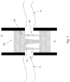
- Fig. 1 shows a prosthetic aortic valve replacement device 100 in the aortic region following implantation.
- the device lies between the heart 10 and the aorta 12 at about the position the aortic valve would normally be located.
- the device 100 includes a polymeric valve 101 mounted in a tubular stent 102.
- the left and right coronary vessels 13/14 or 14/13, depending on whether the depicted view is from above or from below are also shown.
- the tubular stent includes openings 104 positioned such that the coronary vessels 13, 14 are not blocked or occluded.
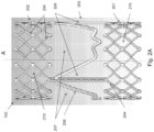
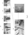
- Figs. 2A , 2B and 2C show views of the tubular stent 102.
- Fig. 2A shows a perspective view.
- Fig. 2B shows a view of the tubular sent sliced along its length and rolled out flat.
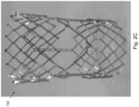
- Fig. 2C is a photograph of an embodiment of the tubular stent 102.
- the tubular stent 102 is disposed about a longitudinal axis A.
- the stent 102 extends from proximal end (towards the bottom of the figures) to a distal end (towards the top of the figures) and defines a tubular passage between the two ends.
- the valve 101 (not shown) is mounted on the stent 102 in the tubular passage transverse to the axis A.
- the stent 102 has a proximal portion 201, a distal portion 202 and a middle potion 203.
- the middle portion 203 is located between the proximal and distal portions 201, 202.
- the proximal and distal portions each include a mesh of support struts 204.
- the support struts are arranged to form rings of open elements 210 (as shown, diamond elements) disposed about the axis A.
- the middle portion 203 includes elongated posts 205 that extend along a direction substantially parallel to the axis A, connecting the proximal portion 201 to the distal portion 202.
- a mounting element for mounting the valve is attached to the posts 205.
- the mounting element is a crown shaped mounting ring 206 suitable for mounting a trileaflet polymeric valve of the type described in greater detail below.
- the points of the crown shaped mounting ring 206 are attached to the posts 205.
- the crown shaped mounting ring 206 may, additionally or alternatively, be attached to the proximal portion 201 of the stent 102. For example, for the embodiment shown, an attachment may be made between the proximal pointing features on the ring 206 between the posts 205.
- the crown shaped mounting ring 206 includes three points extending towards the distal end of the stent 102.
- any other number of points may be used, e.g., 1, 2, 3, 4, 5, etc.
- the mounting element may have any other suitable shape, e.g. a circle, an oval, a ring with sinusoidal undulations towards and away from the distal end of the stent 102, a ring with sawtooth undulations towards and away from the distal end of the stent 102, etc.
- the middle portion 203 also includes open regions 207 located distal the mounting ring 206 that are completely free of posts, struts, or any other structures. These open regions 207 correspond to the openings 104 described with reference to Fig. 1 .
- the area of each of the open regions 207 will be larger than the area of the open elements 210 that form the mesh found in the proximal and distal portions.
- the area of each of the open regions 207 may be at least 2, 3, 4, 5, 10, 20, 30, 40, 50, 60, 70, 80, 90, 100 or more times the area of each of the open elements 210.
- the area of each of the open regions 207 may be in the range of 2-100 times the area of the area of the open elements 210, or any subrange thereof.
- the ratio of areas is about 50.
- the area of the open region 207 is about 300 mm 2
- the area of the open diamond elements 210 is about 6 mm 2 .
- the relatively fine mesh of support struts 204 forming the rings of open elements 210 in the proximal and distal portions 201, 202 provide good mechanical support for the valve 101 and stent 102.
- the larger open regions 207 in the middle portion 203 ensure that the portion of the device 100 located near the coronary ostia is free or substantially free from any obstructions (e.g., as shown in Fig. 1 ).
- the proximal and distal portions 201 and 202 each include three rings of open diamond shaped elements 210 formed from the support struts 204.
- more or fewer rings may be used, e.g., 1, 2, 3, 4, 5, or more rings.
- the elements 210 may have other shapes including rectangular, square, polygonal, round, oval, etc.
- the struts 204 may form a mesh with an irregular or random pattern.
- the number of posts 205 may also be chosen to ensure that the middle portion 203 remains suitably free of obstructions. In some embodiments, no more than, e.g., 6, 5, 4, 3, 2, or 1 posts may be used. In general, the number of posts 205 may be fewer than the number of open elements 210 found in each ring of elements in the proximal and distal portions 201 and 202. For example, in some embodiments there are N open elements 210 in each ring, and M posts 205, where M and N are integers. In some embodiments, the ratio of N to M is at least 2 to 1, 3 to 1, 4 to 1, 5 to 1 (as shown), 6 to 1, 7 to 1, 8 to 1, 9 to 1, 10 to 1 or more.
- the support struts 204 and posts 205 of the stent 102 may be made from any suitable material.
- a shape memory material is used, e.g. a nickel titanium allow such as the material marketed under the trade name Nitinol.
- other materials may be used, alone or in any suitable combination, including metallic, plastic, polymer, or other materials.
- the materials may be biocompatible.
- a sheath 300 is formed that extends along the outer surface of the stent 102 from the proximal portion 201 to the distal portion 202, without substantially covering the open regions 207 of the middle portion 203.
- the sheath 300 may encapsulate the elongated posts 205 and some or all of the support struts 204 of the proximal and/or distal portions 201, 202 of the stent 102.
- the sheath may be made of any suitable material, e.g., a polymer material such as silicone, polyurethane, polyether ether ketone (PEEK), etc. hi some embodiments, the polymer material may be the material produced under the trade name Angioflex by Abiomed, Inc. of Danvers, MA.
- the sheath 300 includes regions of reinforced thickness at locations corresponding to the elongated posts 205 or the support struts 204. In some embodiments, the sheath 300 may be secured to the stent 102 using one or more sutures.
- a polymeric trileaflet valve 101 is mounted on the crown shaped mounting ring 206.
- the sheath 300 may connect to an outer circumference of the body of the valve 101.
- Fig. 5 shows a detailed view of the valve 101.
- the valve 101 includes an annular, generally cylindrical elastomeric valve body 1101 disposed about a central axis 1116, and having a sealable fluid passageway extending axially from an inflow end (as shown, the bottom) to an outflow end (as shown, the top).
- the valve 101 includes a flexible outer portion 1110 connected to the mounting ring 206 (not shown) and having at least three flexible valve posts 1112 each of which extends axially to a valve post tip 1120.
- valve post tip 1120 may be made of a material having greater flexibility than the valve post 1112.
- the valve 101 includes at least three flexible leaflets 1130 each having a free edge 1132, an attached edge 1133 and a belly 1134.
- the attached edge 1133 attaches to the outer portion 1110 to form an attachment curve running along the inner diameter of the outer portion between a pair of valve posts 1112.
- the free edge 1132 defines a free edge curve which extends from a first valve post tip 1120, towards the central axis 1116 and back to second valve post tip 1120.
- the free edges 1132 of adjacent leaflets 1130 define commissures 1135 at each of the valve post tips 1120.
- the free edges 1132 curve upward in the region of the commissures 1135, such mat the leaflets 1130 have a homed shape in the region around each of the valve post tips 1120, as shown.
- the outer portion 1110 of the valve body may be attached to the mounting ring 206.
- the material of the valve body may adhere to and/or encapsulate all or a portion of the ring 206.
- Each of the valve posts 1112 may be attached to a respective one of the elongated posts 205 of the stent 102 (not shown).
- the material of the valve post 1112 may adhere to and/or encapsulate all or a portion of the post 205, e.g., as shown in Fig. 4 .
- the posts 205 may include one or more features that facilitate connection to the valve posts 1112.
- the posts 205 may include holes that allow the material of the valve posts 1112 to extend through and around the post 205, to provide a stronger connection.
- the pressure of the blood flow causes the leaflets 1130 to deflect away from a central axis 1116 of the valve body 1101.
- the leaflets 1130 define a large flow orifice (not shown) allowing the blood to flow freely in the forward direction.
- the valve 101 presents little resistance to fluid flow.
- the pressure of the blood flow causes the valve post tips 1120 and the leaflets 1130 to deflect toward the central axis 1116.
- the leaflets 130 engage each other along the free edges 132, which help the valve 101 seal against reverse flow.
- the leaflets 1130 are cast in a partially open position at rest (i.e. in the absence of forward or reverse fluid pressure against the valve).
- the at rest opening of commissures in the region closest to their respective flexible valve post tip 1120 is in the range of 0.60 mm or less, e.g. about 0.25 mm.
- the open area of the valve 101 in the at-rest position may be a suitable fraction of the open area of the valve in the absence of the leaflets 1130.
- the open area in the partially open at rest positions may be greater than 5%, 10%, 25% or more of the open area, e.g., in the range of 5-10%, 10-20%, 10-30%, or any other suitable range.
- This configuration reduces the energy required to open the leaflets during forward blood flow relative to that required for opening an equivalent valve formed in a closed position at rest.
- the relative ease of opening of valve 101 when formed in the partially open rest position results in a decrease in forward flow pressure loss.
- the partially open rest position leaflet geometry helps ensure a symmetric opening of the leaflets 1130 in response to forward flow, even in cases where the flow is not uniformly distributed (e.g. due to the specifics of the heart anatomy, or other factors).
- the valve can avoid unwanted adhesion of free edges of one or more pairs of adjacent leaflets 1130 to one another. This prevents low fluid velocities in the commissure 1135 between the leaflets 1130.
- this valve structure can reduce or prevent the occurrence a "lazy leaflet”, i.e., a leaflet that does not properly and completely move between its intended open and closes positions.
- Avoiding low fluid flow and/or asymmetric flow patterns allows the valve to be properly washed through by the flow of blood in both forward and reverse directions, reducing or eliminating the build up of unwanted materials in the valve. This can lead to a reduction or even elimination of deleterious effects, e.g., thrombosis.
- the valve posts 1112 When transitioning from the partially open rest position to the closed position, the valve posts 1112 flex inward toward the central axis to allow leaflets 1130 to close properly to seal the valve against reverse flow. This flexing beneficially reduces strain on the leaflets 1130, reducing or eliminating the occurrence of tears, and improving the reliability and durability of the valve 101.
- the tips 1120 of valve posts are formed of a material that is more flexible than the remainder of the valve posts 1112. This allows for increased flexing in the area near the commissures 1135 without compromising the overall structural integrity of posts 1112. Accordingly, force may be transferred from the leaflets 1130 to the valve posts 1112 through tips 1120 while reducing or eliminating unwanted stress concentrations in the leaflets 1130.
- the flexible post tips 1120 serve as a strain relief for the leaflet 1130 transition to the valve posts 1112 while reducing stress concentrations in the leaflets 1130 thereby increasing reliability of the polymeric valve 101.
- relatively short, low profile posts 1112 may be used.
- each flexible valve post tip 1120 extends beyond the free edge 1132 of the leaflets 1130 where the leaflets attach to the posts 1112 (i.e. near commissures 1135). In some embodiments, each flexible tip 1120 extends beyond the free edge of the leaflets by 1 mm to 2 mm, e.g., by 1.5 mm. In some embodiments, this flexible tip configuration acts to reduces stress concentrations between the softer leaflet 1130 material and the harder post 1112 in order to increase the valve reliability. Although not shown, in some embodiments, the posts 205 of the stent 102 extends through the valve posts 1112, and out through the tips 1120.
- a portion of the free edge 1132 of the leaflet 1130 is substantially straight, extending radially towards the central axis 1116. As noted above, in one embodiment, portions of the free edge 1132 of the leaflet 1130 curve upward slightly at the valve post tip 1120.
- the belly 1134 of the leaflet 1130 has a thickness profile less than a thickness profile of the free edge 1132 of the leaflet 1130. The thickness profile of the free edge 1132 can be in the range of 1 to 2.5 times greater than the thickness profile of the belly 1134.
- the leaflets can be made from a biocompatible polymer, such as silicone and/or polyurethane.
- valve 101 any other suitable valve may be used for valve 101 including any suitable polymeric valve known in the art., however according to the invention, the valve is formed by dip molding.
- any suitable dimensions for the device 100 may be used.
- the device 100 has an outer diameter of about 23 mm or about 27 mm. In some embodiments, the device 100 has an outer diameter in the range of 10-100 mm, or any subrange thereof. In some embodiments, the device has a total length of about 48mm. In some embodiments, the device has a total length of in the range of 10-100 mm, or any subrange thereof.
- the wall thickness of the tubular stent 102 is about 0.5 mm. In some embodiments, the wall thickness of the tubular stent 102 is about 0.1-1.0 mm or any subrange thereof.
- the device 100 may be crimped to reduce its outer diameter to allow for percutaneous implantation, e.g., using transcatheter techniques known in the art.
- Fig. 6 illustrates a kit used for crimping the device 100.
- the kit includes a cone 601, a cap 602, and an introducer sleeve 603.
- the device 100 is inserted into the wide end of the cone 601 and capped with the cap 602.
- the introducer sleeve 603 is attached to the device 100 (e.g. using one or more pins which attach to the stent 102).
- the cone 601 is pushed back while the sleeve 603 is advanced.
- the device 100 is crimped as it passes out through the narrow end of the cone and is inserted within the sleeve 100.
- the device 100 may be crimped to any suitable size.
- the device may be crimped to a reduced outer diameter in the range of 4-10 mm, e.g., to a sufficiently small outer diameter for use with a catheter introduction system with a catheter size in the range of 12-30 Fr (in the familiar French catheter size scale).
- positioning of the open regions 207 adjacent the leaflets of the valve 101 allows the device to be crimped down to a small size without damaging the sensitive valve leaflets.
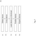
- Fig. 7 is a flow diagram 700 illustrating the steps for implantation of the device 100.
- the device is obtained.
- the device is crimped to reduce its outer diameter.
- the device is loaded on to an introducer (e.g. as described with reference to Fig. 6 ).
- the device is positioned at a desired location in a subject, e.g., using a transcatheter method.
- the device is expanded back to its uncrimped size, e.g., by removing the introducer.
- the device 100 is self expanding (e.g., owing to shape memory properties of the stent 102).
- an expander such as a balloon catheter expander may be used.
- Fig. 8 illustrates a method 800 of making the device 100 shown in Fig. 4 .
- a mandrel is obtained having a portion with a shape corresponding to the shape of the valve 101.
- the stent 102 is obtained and placed over the mandrel.
- the stent may be constructed using any suitable technique known in the art including molding, welding, brazing, etc.
- step 803 the valve 101 is formed on the mandrel, using a dip molding
- the mandrel and the stent 102 may be cleaned with alcohol.
- a polymer conduit is placed on the valve mandrel and the stent 102.
- strips of flexible material e.g., a polymer such as Angioflex
- the mandrel assembly is dipped in a polymer solution having a suitable viscosity, e.g., within the 730 ⁇ 50 cp range.
- the polymer solution can be an Angioflex solution produced by Abiomed of Danvers, MA.
- the valve mandrel is cleaned, e.g. with alcohol.
- valve mandrel is placed upside down in a container of Dioxane, e.g., for 30 seconds so that the entire stent is covered.
- the valve mandrel is dipped in the polymer solution. Once the valve mandrel is removed from the solution any excess solution is removed. The dipping process may be repeated to obtain a desired leaflet profile.
- valve fabrication process has been described above, it is to be understood that any suitable fabrication technique known in the art may be employed, however according to the invention the valve is formed by dip molding.
- the valve 101 may be fabricated using one or more of the techniques described in Labma NMK, Woodhouse KA, Cooper SL. Polyurethanes in Biomedical Applications. 1998 CRC Press LLC, Boca Raton, Florida, p.33 .; Lyman DJ, Searl WJ, Albo D, Bergman S, Lamb J, Metcalf LC, and Richards K. Polyurethane elastomers in surgery. Int J Polym Mater, 5:211, 1977 ; Boretos JW. Procedures for the fabrication of segmented polyurethane polymers into useful biomedical prostheses.
- a heat shrink tube is placed over the conduit and stent 102 on the mandrel.
- the heat shrink tubing may be made of a thermoplastic material such as poly olefin, fluoropolymer (such as fluorinated ethylene propylene, polytetrafluoroethylene or polyvinylidene fluoride), polyvinyl chloride, neoprene, silicone elastomer, Viton, etc.
- step 805 heat is applied, e.g., with a heat gun, to soften the conduit and cause the heat shrink tubing to contract around the mandrel.
- the contracting tubing applies a force which molds the softened material of the conduit, causing it to flow around and encapsulate at least a portion of the stent 102 to form the sheath 300.
- This molding process may be referred to as "thermoforming”.
- the valve 101 is cooled during the thermoforming process (e.g., by application of an air flow), to avoid thermal damage to the valve 101.
- the valve 101 may be cut (e.g., using laser cutting) to free the valve leaflets.
- step 806 the assembly is removed from the mandrel, resulting in the device 100 as shown in Fig. 4 .
- Some embodiments include an additional step (not shown) of securing the sheath 300 to the stent 102 using, e.g. sutures.
- the valve 101 is formed in the partially open position as described above, and may exhibit advantageous hemodynamic performance.
- Fig. 9 shows a table detailing forward pressure loss as a function of flow rate for embodiments of the valve 101 with various leaflet thicknesses.
- the pressure loss increases roughly linearly as a function of flow rate, from a loss of about 6-7 mmHg at a flow rate of 5 L/minute to a loss of about 22-25 mmHg at a flow rate of 25 L/minute.
- Other embodiments may exhibit even lower pressure drops, e.g., reduced by a factor of two or more from the values shown.
- some embodiments may have a pressure drop of about 5 mmHg or less at a flow rate of 10 L/minute.
- this performance is comparable or superior to that of a comparable bioprosthetic valve or a comparable mechanical valve.
- Some embodiments feature the utilization of flexible and peripherally located leaflets which avoid blood flow disturbances such as cavitation and stagnation leading to cell damage and thrombosis. Additional performance benefits include the avoidance of reliability issues typically associated with bioprosthesis (i.e., problems with limited life from structural changes such as calcification and leaflet wear, leading to valve failure -- biological tissue fixation and methods used to mount the tissue to a supporting stent may account for this shortcoming).
- Fig. 10 shows a plot of valve leakage detailing forward pressure loss as a function of flow rate for embodiments of the valve 101 with various leaflet thicknesses.
- the valve leakage rate at a reverse flow pressure of 85 mmHg is less than about 8 mL/second in some embodiments, and less than about 4 mL/second in another embodiment. Further embodiments may have even lower leakage rates. This performance is comparable or superior to that of a comparable mechanical valve or bioprosthesis valve.
- the closing volume loss of for embodiments of the valve 101 may be, e.g., less than about 10 mL, 8 mL 6, mL, 4 mL, 2mL, 1 mL, or less, (e.g., corresponding to a hydraulic efficiency of at least 80%, at least 85%, or more). This performance is comparable or superior to that of a comparable mechanical valve or bioprosthesis valve.
Description
- Prosthetic heart valves are used to replace damaged or diseased heart valves. Prosthetic heart valves for human patients have been available since the 1950s. Today, there are three general types of prosthetic heart valves, including mechanical valves, tissue valves, and polymer valves. In some cases, a heart valve prosthesis is implanted into an annular opening in a patient's heart following surgical removal of a diseased or damaged natural valve. The valve can be secured in the annulus of the opening through the use of sutures or pins that penetrate the host tissue and an outside edge of the valve. Alternatively, the valve can be secured in the annulus by suturing the host tissue to a sewing ring. Heart valves function essentially as one-way check valves for blood flow through the beating heart.
- The term "mechanical valve" refers to mono- or multi-leaflet (typically bi-leaflet) heart valves having a valve orifice fabricated at least in part of a rigid, biologically compatible material such as pyrolytic carbon, and comprising essentially no biological components. The term "bioprosthetic valve" refers to a multi-leaflet (e.g., bi-leaflet or tri-leaflet) heart valve having at least some biological components such as tissue or tissue components. The biological components of tissue valves are obtained from a donor animal (typically bovine or porcine), and the valve may comprise either biological materials alone or biological materials with man-made supports or stents. The term "polymeric valve" refers to a multi-leaflet (e.g., tri-leaflet or bi-leaflet) heart valve having at least some elastomeric polymer components, including at least elastomeric polymer valve leaflets.
- A tri-leaflet heart valve prosthesis typically includes an annular valve body and three flexible leaflets attached thereto. The valve body includes an annular base and three leaflet support posts located at the circumference of the annulus. In some cases, a sewing ring annularly coupled to the periphery of the valve body may provide a place for sutures to be applied when the valve is implanted. The leaflets are attached to the three shaped posts along an attachment curve, and they also each have a free, unattached edge remote from the attachment curve. The place where two adjacent leaflets come together at one of the support posts is called the commissure, and the generally curved area on the leaflet between the free edge and the attachment curve is known as the belly of the leaflet. The free edges of the three leaflets come together at a "triple point" generally on the axis of the valve.
- When blood flows in the forward direction, the energy of the blood flow deflects the three leaflets away from the center of the annulus and allows blood to flow through. When blood flows in the reverse direction, the three leaflets engage each other in a coaptive region, occlude the valve body annulus and prevent the flow of blood.
- Heart valves may be may be implanted through open heart surgical procedures. More recently, heart valves have been developed that are implanted percutaneously, e.g., using transcatheter procedures. Transcatheter percutaneous aortic replacement valve devices typically include a valve body mounted on a tubular expandable (e.g. balloon expandable or self-expanding) stent or frame. Examples include the SAPIEN device available from Edwards Lifesciences of Irvine, CA or the Core Valve device available from Medtronic of Minneapolis, MN.
- Percutaneously implanted devices obviate the need for major open surgical procedures. However, implantation of these devices may be difficult. Replacement valves are typically sensitive devices, and care must be taken to avoid damage during implantation. In the case of aortic replacement valves, further difficulties may arise from the particular anatomy of the aortic region. The aortic region is characterized by high blood pressure subjecting tissue is in the area to high physical strains. Supporting stents for aortic replacement valves therefore must sufficiently be robust and rigid to operate in this environment. However, the introduction of such a stent in the region raises the risk that other vessels, such as the coronary arteries ostium dextra and ostium sinistra (referred to herein as the coronary ostia) descending on both sides of the aorta, may be disrupted in their function.
-
WO2007/081820 describes a replacement valve apparatus including a docking station, a self -expanding member, and a valve frame. The valve frame is adapted to be positioned within the docking station, whereas the self-expanding member is adapted to be associated with an outer wall of the docking station. The valve frame generally includes a substantially cylindrical body defining a lumen and a plurality of curved support structures attached to the substantially cylindrical body. The valve frame further can have a plurality of leaflets. Each leaflet can be attached to a respective inner curved support structure and can extend over a respective outer curved support structure, so as to position the body of the leaflet within the lumen of the valve frame. -
AU2002212418 -
US2006/0122693 describes a stent valve which includes a scaffold, the scaffold including interlinked struts, the scaffold having a scaffold passageway extending substantially longitudinally therethrough. The stent valve also includes a valve leaflet extending at least partially across the scaffold passageway, the valve leaflet defining a leaflet periphery. At least a portion of the leaflet periphery extends integrally from at least a portion of at least one of the struts and at least a portion of the leaflet periphery is substantially parallel to the at least a portion of said at least one of said struts. -
US2010/168839 describes a prosthetic heart valve designed to be circumferentially collapsible and then re-expandable. When the valve reaches the implant site in the patient, it re-expands to normal operating size, and also to engage surrounding tissue of the patient. The valve includes a stent portion and a ring portion that is substantially concentric with the stent portion but downstream from the stent portion in the direction of blood flow through the implanted valve. When the valve is implanted, the stent portion engages the patient's tissue at or near the native valve annulus, while the ring portion engages tissue downstream from the native valve site (e.g., the aorta). - The invention relates to a prosthetic apparatus according to
claim 1. The invention also relates to a method of making a prosthetic apparatus according to claim 11. Further advantageous embodiments are described in the dependent claims. - The inventors have realized that a percutaneously implantable aortic replacement valve device may be provided featuring, e.g., a polymeric tri-leaflet valve mounted in an expandable stent. As detailed herein, the stent may include one or more open regions adjacent the valve at positions corresponding to the coronary ostia. This allows the device to be implanted more easily, and reduces the risk of damaging, blocking, or otherwise disrupting the function of the ostia lowers the incidence of unwanted effects such as stenosis. Further, in cases where the device is an expandable device, positioning of the open regions adjacent the leaflets of the valve allows the device to be crimped down to a small size without damaging the sensitive valve leaflets.
- The inventors have realized that a multi-leaflet polymeric heart valve (e.g. a tri-leaflet valve) may be mounted on the stent. In some embodiments, the valve features a partially open leaflet position which reduces forward flow pressure loss. In some embodiments, the valve features flexible valve posts with tips made of a soft flexible material. The flexibility of the posts allows the leaflets to properly close to block reverse blood flow without experiencing excessive stress or strain. These features act synergistically to provide a valve with advantageous durability, forward flow pressure loss and efficiency characteristics.
- In one aspect, a prosthetic apparatus is disclosed including: a tubular stent disposed about a longitudinal axis and extending from a proximal end to a distal end, the stent defining a tubular passage between the ends. In some embodiments, the tubular stent has a proximal portion, a distal portion, and a middle portion located between the proximal and distal portions, hi some embodiments, the proximal and distal portions each include a mesh of support struts forming at least one ring of open elements disposed about the longitudinal axis. In some embodiments, the middle portion includes: a plurality of elongated posts extending along a direction substantially parallel the longitudinal axis between the proximal and distal portions; and a crown shaped mounting ring attached to the posts and configured to mount a polymeric valve within the tubular passage; and a plurality of open regions. In some embodiments, the crown shaped ring may, additionally, or alternatively, be attached to the proximal portion of the stent.
- In some embodiments, the open elements are open diamond shaped elements.
- In some embodiments, the plurality of open regions each define an open area along the outer surface of the tubular support that is at least about 20 times the area of each of the open elements.
- In some embodiments, the plurality of open regions each define an open area along the outer surface of the tubular support that is at least about 40 times the area of each of the open elements.
- In some embodiments, the proximal and distal portions include a ring of N open elements, the plurality of stent posts consist of M posts extending between the rings, and the ratio of N to M is at least 4 to 1, at least 5 to 1, or is at least 6 to 1. In some embodiments, N=15 and M=3.
- According to the invention, the apparatus includes a tubular polymeric sheath extending along the outer surface of the tubular support member from the proximal portion to the distal portion, but does not substantially cover the open regions in the middle portion. In some embodiments, the sheath encapsulates the elongated posts.
- In some embodiments, the sheath includes regions of reinforced thickness corresponding to the elongated posts.
- In some embodiments, the sheath includes regions of reinforced thickness corresponding to one or more of the support struts or the mounting ring.
- Some embodiments include one or more sutures securing the sleeve to the stent.
- Some embodiments include the polymeric heart valve. In some embodiments, the valve includes: a valve body having a central axis extending along the direction of the longitudinal axis of the tubular stent and having a body fluid pathway extending along the central axis from an inflow end to an outflow end; a flexible outer support disposed about an outer circumference of the body and including at least three flexible valve posts each extending in the axial direction to a tip and each attached to at least one of the elongated posts; and at least three flexible leaflets extending from the crown shaped mounting ring, each of the leaflets having an attached edge defining an attachment curve along the mounting ring extending between a respective pair of flexible valve posts, and where pairs of leaflets define a respective commissure at each of the at least three flexible valve posts; where the crown shape ring includes a plurality of points each corresponding to a flexible valve post and attached to a respective one of the elongated posts of the stent.
- In some embodiments, the flexible outer support of the valve encapsulates a portion of the tubular stent, hi some embodiments, the stents posts extend through the flexible outer support, e.g., extending through the valve posts.
- In some embodiments, the at least three leaflets define a partially open position at rest, a fully open position deflecting away from the central axis during forward blood flow along a direction from the inflow end to the outflow end, and a closed position deflecting toward the central axis during reverse blood flow along a direction from the outflow end to the inflow end, and in the closed position, each of the flexible valve posts flexes inward toward the central axis.
- In some embodiments, the tip of each valve post is formed of a material having a flexibility greater than the remainder of the valve post.
- In some embodiments, the stent is configured to be crimped to reduce the outer diameter of the stent from an uncrimped diameter to a crimped diameter without damaging the valve. In some embodiments, the uncrimped diameter is at least about 20 mm and the crimped diameter is less than about 6 mm.
- In some embodiments, the tubular stent includes a shape memory material. In some embodiments, the shape memory material includes Nitinol.
- In some embodiments, stent is a self expanding stent.
- In some embodiments, the stent is configured such that, when implanted in the human heart such that the valve is positioned proximal the location of the native aortic valve, the open regions are positioned proximal to the coronary ostia.
- In some embodiments, the apparatus consists essentially of biocompatible materials.
- A method is disclosed including: obtaining the apparatus of any of the types described above; and percutaneously implanting the apparatus in a human subject such that that the valve is positioned proximal the location of the native aortic valve, the open regions are positioned proximal to the coronary ostia.
- The step of percutaneously implanting the apparatus includes: crimping the stent; using an introducer to position the stent in a desired location; and removing the introducer and expanding the stent to an uncrimped state.
- Expanding the stent to an uncrimped state includes allowing the stent to self expand.
- In another aspect, a method of making prosthetic apparatus is disclosed including: obtaining a tubular stent of any of the types described above; placing the stent on a mandrel; forming a polymeric valve mounted on the mounting ring by a process including dip molding; forming a tubular polymeric sheath extending along the outer surface of the tubular support member from the proximal portion to the distal portion, but does not substantially cover the open regions in the middle portion.
- According to the invention, the step of forming the tubular polymeric sheath includes a thermoforming process including: applying a polymer material to the outer surface of the tubular stent; disposing a heat shrink tube about the polymer material and the stent; applying heat to soften the polymer material and cause the heat shrink tube to shrink and apply force to mold the polymer material to form the sheath.
- In some embodiments, forming the sheath includes encapsulating one or more of the support struts and the elongated posts.
- Some embodiments include, during the thermoforming process, applying an air flow to valve to avoid thermal damage to the valve.
- Some embodiments include applying strips of polymer material to reinforce the sheath at locations corresponding to the elongated posts or the mounting ring.
- Some embodiments include applying additional polymer material to reinforce the sheath at locations corresponding to the struts.
-
-
Fig. 1 illustrates a prosthetic aortic valve replacement device in the aortic region following implantation. -
Fig. 2A shows a perspective view of a tubular stent. For clarity, only one half of the tubular stent is shown. The remaining half of the stent may be obtained by reflection in a plane that slices through the tubular stent and includes the longitudinal axis A. -
Fig. 2B shows a view of the tubular stent ofFig. 2A having been cut along its length and laid flat. -
Fig. 2C is a photograph of a stent of the type illustrated inFigs. 2A and2B . -
Fig. 3 shows a stent ofFigs. 2A-C in same view found inFig. 2B , further including a sheath on the stent. The sheath is indicated by the gray area. -
Fig. 4 is a photograph of a prosthetic aortic valve replacement device including the stent shown inFig. 2C with a polymeric sheath and valve attached. -
Fig. 5 is a detailed illustration of the valve of the prosthetic aortic valve replacement device shown inFig. 4 . -
Fig. 6 is an illustration of a kit for crimping the prosthetic device ofFig. 4 onto a introducer. -
Fig. 7 is a flow chart illustrating the steps for implanting a prosthetic device. -
Fig. 8 is an illustration of a method of making the prosthetic device ofFig. 4 . -
Fig. 9 is a table showing forward pressure loss as a function of flow rate for embodiments of a valve with various leaflet thicknesses mounted on a stent featuring a crown shaped mounting ring of the type shown inFigs. 2A-2C . -
Fig. 10 is a table showing backflow leakage for embodiments of a valve with various leaflet thicknesses mounted on a stent featuring a crown shaped mounting ring of the type shown inFigs. 2A-2C . - Generally, the present technology relates to a percutaneously implantable device that includes a polymeric heart valve. The device includes openings that prevent blockage or damage of anatomical features at the implantation site.
- For example,
Fig. 1 shows a prosthetic aorticvalve replacement device 100 in the aortic region following implantation. The device lies between theheart 10 and theaorta 12 at about the position the aortic valve would normally be located. As detailed below, thedevice 100 includes apolymeric valve 101 mounted in atubular stent 102. The left and rightcoronary vessels 13/14 or 14/13, depending on whether the depicted view is from above or from below are also shown. The tubular stent includesopenings 104 positioned such that thecoronary vessels -
Figs. 2A ,2B and2C show views of thetubular stent 102.Fig. 2A shows a perspective view.Fig. 2B shows a view of the tubular sent sliced along its length and rolled out flat.Fig. 2C is a photograph of an embodiment of thetubular stent 102. - Referring to
Figs. 2A-2C , thetubular stent 102 is disposed about a longitudinal axis A. Thestent 102 extends from proximal end (towards the bottom of the figures) to a distal end (towards the top of the figures) and defines a tubular passage between the two ends. The valve 101 (not shown) is mounted on thestent 102 in the tubular passage transverse to the axis A. - The
stent 102 has aproximal portion 201, adistal portion 202 and amiddle potion 203. Themiddle portion 203 is located between the proximal anddistal portions - The
middle portion 203 includeselongated posts 205 that extend along a direction substantially parallel to the axis A, connecting theproximal portion 201 to thedistal portion 202. A mounting element for mounting the valve is attached to theposts 205. As shown, the mounting element is a crown shaped mountingring 206 suitable for mounting a trileaflet polymeric valve of the type described in greater detail below. The points of the crown shaped mountingring 206 are attached to theposts 205. In some embodiments, the crown shaped mountingring 206 may, additionally or alternatively, be attached to theproximal portion 201 of thestent 102. For example, for the embodiment shown, an attachment may be made between the proximal pointing features on thering 206 between theposts 205. - As shown the crown shaped mounting
ring 206 includes three points extending towards the distal end of thestent 102. However, in other embodiments, any other number of points may be used, e.g., 1, 2, 3, 4, 5, etc. In some embodiments, the mounting element may have any other suitable shape, e.g. a circle, an oval, a ring with sinusoidal undulations towards and away from the distal end of thestent 102, a ring with sawtooth undulations towards and away from the distal end of thestent 102, etc. - The
middle portion 203 also includesopen regions 207 located distal the mountingring 206 that are completely free of posts, struts, or any other structures. Theseopen regions 207 correspond to theopenings 104 described with reference toFig. 1 . - In typical embodiments, the area of each of the
open regions 207 will be larger than the area of theopen elements 210 that form the mesh found in the proximal and distal portions. For example, in various embodiments, the area of each of theopen regions 207 may be at least 2, 3, 4, 5, 10, 20, 30, 40, 50, 60, 70, 80, 90, 100 or more times the area of each of theopen elements 210. For example, in some embodiments, the area of each of theopen regions 207 may be in the range of 2-100 times the area of the area of theopen elements 210, or any subrange thereof. As shown, the ratio of areas is about 50. For example, in one embodiment, the area of theopen region 207 is about 300 mm2, while the area of theopen diamond elements 210 is about 6 mm2. - Accordingly, the relatively fine mesh of support struts 204 forming the rings of
open elements 210 in the proximal anddistal portions valve 101 andstent 102. Meanwhile, the largeropen regions 207 in themiddle portion 203 ensure that the portion of thedevice 100 located near the coronary ostia is free or substantially free from any obstructions (e.g., as shown inFig. 1 ). - As shown, the proximal and
distal portions elements 210 formed from the support struts 204. In other embodiments, more or fewer rings may be used, e.g., 1, 2, 3, 4, 5, or more rings. In various embodiments theelements 210 may have other shapes including rectangular, square, polygonal, round, oval, etc. In some embodiments thestruts 204 may form a mesh with an irregular or random pattern. - The number of
posts 205 may also be chosen to ensure that themiddle portion 203 remains suitably free of obstructions. In some embodiments, no more than, e.g., 6, 5, 4, 3, 2, or 1 posts may be used. In general, the number ofposts 205 may be fewer than the number ofopen elements 210 found in each ring of elements in the proximal anddistal portions open elements 210 in each ring, andM posts 205, where M and N are integers. In some embodiments, the ratio of N to M is at least 2 to 1, 3 to 1, 4 to 1, 5 to 1 (as shown), 6 to 1, 7 to 1, 8 to 1, 9 to 1, 10 to 1 or more. For example, in the embodiment shown, the proximal anddistal portions open diamond elements 210, with each ring having fifteenelements 210, therefore N=15. This embodiments has threeposts 205, therefore M=3, giving a ration of N to M of 5 to 1. - The support struts 204 and
posts 205 of thestent 102 may be made from any suitable material. In some embodiments, a shape memory material is used, e.g. a nickel titanium allow such as the material marketed under the trade name Nitinol. In various embodiments, other materials may be used, alone or in any suitable combination, including metallic, plastic, polymer, or other materials. In various embodiments, the materials may be biocompatible. - Referring to
Fig. 3 , according to the invention, asheath 300 is formed that extends along the outer surface of thestent 102 from theproximal portion 201 to thedistal portion 202, without substantially covering theopen regions 207 of themiddle portion 203. Thesheath 300 may encapsulate theelongated posts 205 and some or all of the support struts 204 of the proximal and/ordistal portions stent 102. - The sheath may be made of any suitable material, e.g., a polymer material such as silicone, polyurethane, polyether ether ketone (PEEK), etc. hi some embodiments, the polymer material may be the material produced under the trade name Angioflex by Abiomed, Inc. of Danvers, MA. In some embodiments, the
sheath 300 includes regions of reinforced thickness at locations corresponding to theelongated posts 205 or the support struts 204. In some embodiments, thesheath 300 may be secured to thestent 102 using one or more sutures. - As shown in
Fig. 4 , in some embodiments, apolymeric trileaflet valve 101 is mounted on the crown shaped mountingring 206. Thesheath 300 may connect to an outer circumference of the body of thevalve 101. -
Fig. 5 shows a detailed view of thevalve 101. Thevalve 101 includes an annular, generally cylindrical elastomeric valve body 1101 disposed about a central axis 1116, and having a sealable fluid passageway extending axially from an inflow end (as shown, the bottom) to an outflow end (as shown, the top). Thevalve 101 includes a flexibleouter portion 1110 connected to the mounting ring 206 (not shown) and having at least three flexible valve posts 1112 each of which extends axially to avalve post tip 1120. As discussed in greater detail below,valve post tip 1120 may be made of a material having greater flexibility than the valve post 1112. - The
valve 101 includes at least three flexible leaflets 1130 each having a free edge 1132, an attached edge 1133 and abelly 1134. The attached edge 1133 attaches to theouter portion 1110 to form an attachment curve running along the inner diameter of the outer portion between a pair of valve posts 1112. The free edge 1132 defines a free edge curve which extends from a firstvalve post tip 1120, towards the central axis 1116 and back to secondvalve post tip 1120. The free edges 1132 of adjacent leaflets 1130 define commissures 1135 at each of thevalve post tips 1120. In some embodiments, the free edges 1132 curve upward in the region of the commissures 1135, such mat the leaflets 1130 have a homed shape in the region around each of thevalve post tips 1120, as shown. - The
outer portion 1110 of the valve body may be attached to the mountingring 206. For example, in some embodiments, the material of the valve body may adhere to and/or encapsulate all or a portion of thering 206. - Each of the valve posts 1112 may be attached to a respective one of the
elongated posts 205 of the stent 102 (not shown). For example, in some embodiments, the material of the valve post 1112 may adhere to and/or encapsulate all or a portion of thepost 205, e.g., as shown inFig. 4 . In some embodiments, theposts 205 may include one or more features that facilitate connection to the valve posts 1112. For example, as shown inFigs. 2A-4 , theposts 205 may include holes that allow the material of the valve posts 1112 to extend through and around thepost 205, to provide a stronger connection. - In operation, when blood flows in the forward direction, i.e., towards the top of the figure, the pressure of the blood flow causes the leaflets 1130 to deflect away from a central axis 1116 of the valve body 1101. In this "open" position, the leaflets 1130 define a large flow orifice (not shown) allowing the blood to flow freely in the forward direction. With the leaflets 1130 in the open position, the
valve 101 presents little resistance to fluid flow. When blood flows in the reverse direction, i.e., towards the bottom of the figure, the pressure of the blood flow causes thevalve post tips 1120 and the leaflets 1130 to deflect toward the central axis 1116. In this "closed" position, theleaflets 130 engage each other along thefree edges 132, which help thevalve 101 seal against reverse flow. - As shown, the leaflets 1130 are cast in a partially open position at rest (i.e. in the absence of forward or reverse fluid pressure against the valve). For example, in some embodiments the at rest opening of commissures in the region closest to their respective flexible
valve post tip 1120 is in the range of 0.60 mm or less, e.g. about 0.25 mm. - For example, the open area of the
valve 101 in the at-rest position (e.g., the open cross sectional area presented to fluid flow through the valve) may be a suitable fraction of the open area of the valve in the absence of the leaflets 1130. In some embodiments the open area in the partially open at rest positions may be greater than 5%, 10%, 25% or more of the open area, e.g., in the range of 5-10%, 10-20%, 10-30%, or any other suitable range. - This configuration reduces the energy required to open the leaflets during forward blood flow relative to that required for opening an equivalent valve formed in a closed position at rest. The relative ease of opening of
valve 101 when formed in the partially open rest position results in a decrease in forward flow pressure loss. - Furthermore, the partially open rest position leaflet geometry helps ensure a symmetric opening of the leaflets 1130 in response to forward flow, even in cases where the flow is not uniformly distributed (e.g. due to the specifics of the heart anatomy, or other factors). For example, by providing the leaflets 1130 in the partially open rest configuration, the valve can avoid unwanted adhesion of free edges of one or more pairs of adjacent leaflets 1130 to one another. This prevents low fluid velocities in the commissure 1135 between the leaflets 1130.
- Moreover, this valve structure can reduce or prevent the occurrence a "lazy leaflet", i.e., a leaflet that does not properly and completely move between its intended open and closes positions.
- Avoiding low fluid flow and/or asymmetric flow patterns allows the valve to be properly washed through by the flow of blood in both forward and reverse directions, reducing or eliminating the build up of unwanted materials in the valve. This can lead to a reduction or even elimination of deleterious effects, e.g., thrombosis.
- When transitioning from the partially open rest position to the closed position, the valve posts 1112 flex inward toward the central axis to allow leaflets 1130 to close properly to seal the valve against reverse flow. This flexing beneficially reduces strain on the leaflets 1130, reducing or eliminating the occurrence of tears, and improving the reliability and durability of the
valve 101. Moreover, in some embodiments, thetips 1120 of valve posts are formed of a material that is more flexible than the remainder of the valve posts 1112. This allows for increased flexing in the area near the commissures 1135 without compromising the overall structural integrity of posts 1112. Accordingly, force may be transferred from the leaflets 1130 to the valve posts 1112 throughtips 1120 while reducing or eliminating unwanted stress concentrations in the leaflets 1130. In other words, theflexible post tips 1120 serve as a strain relief for the leaflet 1130 transition to the valve posts 1112 while reducing stress concentrations in the leaflets 1130 thereby increasing reliability of thepolymeric valve 101. Note also that, due to the transition from stiff to soft material in thepost tips 1120, relatively short, low profile posts 1112 may be used. - In some embodiments, each flexible
valve post tip 1120 extends beyond the free edge 1132 of the leaflets 1130 where the leaflets attach to the posts 1112 (i.e. near commissures 1135). In some embodiments, eachflexible tip 1120 extends beyond the free edge of the leaflets by 1 mm to 2 mm, e.g., by 1.5 mm. In some embodiments, this flexible tip configuration acts to reduces stress concentrations between the softer leaflet 1130 material and the harder post 1112 in order to increase the valve reliability. Although not shown, in some embodiments, theposts 205 of thestent 102 extends through the valve posts 1112, and out through thetips 1120. - In some embodiments, a portion of the free edge 1132 of the leaflet 1130 is substantially straight, extending radially towards the central axis 1116. As noted above, in one embodiment, portions of the free edge 1132 of the leaflet 1130 curve upward slightly at the
valve post tip 1120. In one embodiment, thebelly 1134 of the leaflet 1130 has a thickness profile less than a thickness profile of the free edge 1132 of the leaflet 1130. The thickness profile of the free edge 1132 can be in the range of 1 to 2.5 times greater than the thickness profile of thebelly 1134. The leaflets can be made from a biocompatible polymer, such as silicone and/or polyurethane. - In various embodiments any other suitable valve may be used for
valve 101 including any suitable polymeric valve known in the art., however according to the invention, the valve is formed by dip molding. - In various embodiments any suitable dimensions for the
device 100 may be used. For example, in some embodiments, thedevice 100 has an outer diameter of about 23 mm or about 27 mm. In some embodiments, thedevice 100 has an outer diameter in the range of 10-100 mm, or any subrange thereof. In some embodiments, the device has a total length of about 48mm. In some embodiments, the device has a total length of in the range of 10-100 mm, or any subrange thereof. In some embodiments, the wall thickness of thetubular stent 102 is about 0.5 mm. In some embodiments, the wall thickness of thetubular stent 102 is about 0.1-1.0 mm or any subrange thereof. - In some embodiments, the
device 100 may be crimped to reduce its outer diameter to allow for percutaneous implantation, e.g., using transcatheter techniques known in the art. For example,Fig. 6 illustrates a kit used for crimping thedevice 100. The kit includes acone 601, a cap 602, and anintroducer sleeve 603. Thedevice 100 is inserted into the wide end of thecone 601 and capped with the cap 602. Theintroducer sleeve 603 is attached to the device 100 (e.g. using one or more pins which attach to the stent 102). Thecone 601 is pushed back while thesleeve 603 is advanced. Thedevice 100 is crimped as it passes out through the narrow end of the cone and is inserted within thesleeve 100. - In various embodiments, the
device 100 may be crimped to any suitable size. In some embodiments, e.g., where thedevice 100 has an outer diameter in the range of 20-30 mm, the device may be crimped to a reduced outer diameter in the range of 4-10 mm, e.g., to a sufficiently small outer diameter for use with a catheter introduction system with a catheter size in the range of 12-30 Fr (in the familiar French catheter size scale). Advantageously, in some embodiments, positioning of theopen regions 207 adjacent the leaflets of thevalve 101 allows the device to be crimped down to a small size without damaging the sensitive valve leaflets. -
Fig. 7 is a flow diagram 700 illustrating the steps for implantation of thedevice 100. Instep 701, the device is obtained. Instep 702 the device is crimped to reduce its outer diameter. Instep 703 the device is loaded on to an introducer (e.g. as described with reference toFig. 6 ). Instep 704 the device is positioned at a desired location in a subject, e.g., using a transcatheter method. In step, 705 the device is expanded back to its uncrimped size, e.g., by removing the introducer. In some embodiments thedevice 100 is self expanding (e.g., owing to shape memory properties of the stent 102). In some embodiments an expander, such as a balloon catheter expander may be used. -
Fig. 8 illustrates amethod 800 of making thedevice 100 shown inFig. 4 . Instep 801, a mandrel is obtained having a portion with a shape corresponding to the shape of thevalve 101. Instep 802, thestent 102 is obtained and placed over the mandrel. The stent may be constructed using any suitable technique known in the art including molding, welding, brazing, etc. - In
step 803, thevalve 101 is formed on the mandrel, using a dip molding - For example, in some embodiments, the mandrel and the
stent 102 may be cleaned with alcohol. Next, a polymer conduit is placed on the valve mandrel and thestent 102. Optionally, strips of flexible material (e.g., a polymer such as Angioflex) may be adhered theposts 205 of thestent 102 to form the to reinforce this area. The mandrel assembly is dipped in a polymer solution having a suitable viscosity, e.g., within the 730±50 cp range. In some embodiments, the polymer solution can be an Angioflex solution produced by Abiomed of Danvers, MA. At this step, the valve mandrel is cleaned, e.g. with alcohol. Next, the valve mandrel is placed upside down in a container of Dioxane, e.g., for 30 seconds so that the entire stent is covered. Next, the valve mandrel is dipped in the polymer solution. Once the valve mandrel is removed from the solution any excess solution is removed. The dipping process may be repeated to obtain a desired leaflet profile. - Although one valve fabrication process has been described above, it is to be understood that any suitable fabrication technique known in the art may be employed, however according to the invention the valve is formed by dip molding.
- For example, the
valve 101 may be fabricated using one or more of the techniques described in Labma NMK, Woodhouse KA, Cooper SL. Polyurethanes in Biomedical Applications. 1998 CRC Press LLC, Boca Raton, Florida, p.33.; Lyman DJ, Searl WJ, Albo D, Bergman S, Lamb J, Metcalf LC, and Richards K. Polyurethane elastomers in surgery. Int J Polym Mater, 5:211, 1977; Boretos JW. Procedures for the fabrication of segmented polyurethane polymers into useful biomedical prostheses. National Institutes of Health, 1968.; snf Kardos JL, Mehta BS, Apostolou SF, Thies C, and Clark RE. Design, fabrication and testing of prosthetic blood vessels. Biomater Med Dev Artif Organs, 2:387, 1974. - In
step 804, after molding the valve, a heat shrink tube is placed over the conduit andstent 102 on the mandrel. The heat shrink tubing may be made of a thermoplastic material such as poly olefin, fluoropolymer (such as fluorinated ethylene propylene, polytetrafluoroethylene or polyvinylidene fluoride), polyvinyl chloride, neoprene, silicone elastomer, Viton, etc. - In
step 805, heat is applied, e.g., with a heat gun, to soften the conduit and cause the heat shrink tubing to contract around the mandrel. The contracting tubing applies a force which molds the softened material of the conduit, causing it to flow around and encapsulate at least a portion of thestent 102 to form thesheath 300. This molding process may be referred to as "thermoforming". In some embodiments, thevalve 101 is cooled during the thermoforming process (e.g., by application of an air flow), to avoid thermal damage to thevalve 101. - After cooling, the heat shrink tubing is removed (e.g. cut and peeled away). The
valve 101 may be cut (e.g., using laser cutting) to free the valve leaflets. - In
step 806, the assembly is removed from the mandrel, resulting in thedevice 100 as shown inFig. 4 . Some embodiments include an additional step (not shown) of securing thesheath 300 to thestent 102 using, e.g. sutures. - In some embodiments, the
valve 101 is formed in the partially open position as described above, and may exhibit advantageous hemodynamic performance.Fig. 9 shows a table detailing forward pressure loss as a function of flow rate for embodiments of thevalve 101 with various leaflet thicknesses. The pressure loss increases roughly linearly as a function of flow rate, from a loss of about 6-7 mmHg at a flow rate of 5 L/minute to a loss of about 22-25 mmHg at a flow rate of 25 L/minute. Other embodiments may exhibit even lower pressure drops, e.g., reduced by a factor of two or more from the values shown. For example, some embodiments may have a pressure drop of about 5 mmHg or less at a flow rate of 10 L/minute. - In some embodiments, this performance is comparable or superior to that of a comparable bioprosthetic valve or a comparable mechanical valve. Some embodiments feature the utilization of flexible and peripherally located leaflets which avoid blood flow disturbances such as cavitation and stagnation leading to cell damage and thrombosis. Additional performance benefits include the avoidance of reliability issues typically associated with bioprosthesis (i.e., problems with limited life from structural changes such as calcification and leaflet wear, leading to valve failure -- biological tissue fixation and methods used to mount the tissue to a supporting stent may account for this shortcoming).
-
Fig. 10 shows a plot of valve leakage detailing forward pressure loss as a function of flow rate for embodiments of thevalve 101 with various leaflet thicknesses. The valve leakage rate at a reverse flow pressure of 85 mmHg is less than about 8 mL/second in some embodiments, and less than about 4 mL/second in another embodiment. Further embodiments may have even lower leakage rates. This performance is comparable or superior to that of a comparable mechanical valve or bioprosthesis valve. - The closing volume loss of for embodiments of the
valve 101 may be, e.g., less than about 10 mL, 8 mL 6, mL, 4 mL, 2mL, 1 mL, or less, (e.g., corresponding to a hydraulic efficiency of at least 80%, at least 85%, or more). This performance is comparable or superior to that of a comparable mechanical valve or bioprosthesis valve.
Claims (15)
- A prosthetic apparatus comprising:a polymeric valve (101); anda tubular stent (102) disposed about a longitudinal axis (A) and extending from a proximal end to a distal end, the stent (120) defining a tubular passage between the ends;wherein the tubular stent (102) has a proximal portion (201), a distal portion (202), and a middle portion (203) located between the proximal (201) and distal (202) portions;wherein the proximal (201) and distal (202) portions each comprise a mesh of support struts (204) forming at least one ring of open elements (210) disposed about the longitudinal axis (A);wherein the middle portion (203) comprises:a plurality of elongated posts (205) extending along a direction substantially parallel the longitudinal axis (A) between the proximal (201) and distal (202) portions;a crown shaped mounting ring (206) attached to the posts (205) and configured to mount the polymeric valve (101) within the tubular passage; anda plurality of open regions (104, 207) distal to the mounting ring (206) that are free of elongated posts, support struts, or other structures;wherein:
the apparatus further comprises:
a tubular, polymeric sheath (300) extending along the outer surface of the tubular stent (102) from the proximal portion (201) to the distal portion (202), but not substantially covering the open regions (104, 207) in the middle portion (203), wherein the sheath (300) is heat-shrunk onto the stent (102),characterized in that the sheath (300) is molded by disposing a heat shrink tube about the polymer material and the stent (102) and applying heat to soften the polymer material and cause the heat shrink tube to shrink and apply force to mold the polymer material to cause the sheath (300) to flow around and encapsulate at least a portion of the stent (102) to form the sheath (300) and the polymeric valve (101) is formed by dip molding. - The apparatus of claim 1, wherein the open elements (210) are open diamond shaped elements.
- The apparatus of claim 1 or 2, wherein the sheath (300) encapsulates the elongated posts (205).
- The apparatus of claim 3, wherein the sheath (300) comprises regions of reinforced thickness corresponding to the elongated posts (205).
- The apparatus of claim 3 or 4, wherein the sheath (300) comprises regions of reinforced thickness corresponding to one or more of the support struts (204) or the mounting ring (206).
- The apparatus of any one of the preceding claims, wherein the polymeric valve (101) comprises:a valve body (1101) having a central axis (1116) extending along the direction of the longitudinal axis (A) of the tubular stent (102) and having a body fluid pathway extending along the central axis (1116) from an inflow end to an outflow end;a flexible outer support (1110) disposed about an outer circumference of the body (1101) and connected to the mounting ring (206), the outer support (1110) comprising at least three flexible valve posts (1112) each extending in the axial direction to a tip (1120) and each attached to at least one of the elongated posts (205); andat least three flexible leaflets (1130) extending from the crown shaped mounting ring (206), each of the leaflets (1130) having an attached edge (1133) attached to the outer support (1110) defining an attachment curve along the mounting ring (206) extending between a respective pair of flexible valve posts (1112), andwherein pairs of leaflets (1130) define a respective commissure (1135) at each of the at least three flexible valve posts (1112);wherein the crown shaped mounting ring (206) comprises a plurality of points each corresponding to a flexible valve post (1112) and attached to a respective one of the elongated posts (205) of the stent (102).
- The apparatus of claim 6, wherein the tip (1120) of each valve post (1112) is formed of a material having a flexibility greater than the remainder of the valve post (1112); and/or optionallywherein the stent (102) is configured to be crimped to reduce the outer diameter of the stent from an uncrimped diameter to a crimped diameter without damaging the polymeric valve (101); and/or optionallywherein the uncrimped diameter is at least about 20 mm and the crimped diameter is less than about 6 mm.
- The apparatus of any one of the preceding claims, wherein the tubular stent (102) comprises a shape memory material, and, optionally, wherein the shape memory material comprises Nitinol.
- The apparatus of any one of the preceding claims, wherein the stent (102) is a self expanding stent.
- The apparatus of any one of the preceding claims, wherein the stent (102) is configured such that, when implanted in the human heart such that the polymeric valve (101) is positioned proximal the location of the native aortic valve, the open regions are positioned proximal to the coronary ostia; and/or optionally
wherein the apparatus consists essentially of biocompatible materials. - A method of making prosthetic apparatus comprising:obtaining a tubular stent (102) disposed about a longitudinal axis (A) and extending from a proximal end to a distal end, the stent (102) defining a tubular passage between the ends;wherein the tubular stent (102) has a proximal portion (201), a distal portion (202), and a middle portion (203) located between the proximal (201) and distal (202) portions;wherein the proximal (201) and distal (202) portions each comprise a mesh of support struts (204) forming at least one ring of open elements (210) disposed about the longitudinal axis (A);wherein the middle portion (203) comprises:a plurality of elongated posts (205) extending along a direction substantially parallel the longitudinal axis (A) between the proximal (201) and distal (202) portions; anda crown shaped mounting ring (206) attached to the posts (205) and configured to mount a polymeric valve (101) within the tubular passage; anda plurality of open regions (104, 207) distal to the mounting ring (206) that are free of elongated posts, support struts, or other structures;placing the stent (102) on a mandrel;forming a polymeric valve (101) mounted on the mounting ring (206) by a process comprising dip molding; andforming a tubular polymeric sheath (300) extending along the outer surface of the tubular stent (102) from the proximal portion (201) to the distal portion (202), but not substantially covering the open regions (104, 207) in the middle portion (203),wherein said forming the tubular polymeric sheath (300) includes a thermoforming process comprising:applying a polymer material to the outer surface of the tubular stent (102);disposing a heat shrink tube about the polymer material and the stent (102);
andapplying heat to soften the polymer material and cause the heat shrink tube to shrink and apply force to mold the polymer material to form the sheath (300). - The method of claim 11, wherein forming the sheath (300) comprises encapsulating one or more of the support struts (204) and the elongated posts (205).
- The method of claim 11 or 12, further comprising, during the thermoforming process, applying an air flow to the polymeric valve (101) to avoid thermal damage to the polymeric valve (101).
- The method of any one of claims 11 to 13 further comprising applying strips of polymer material to reinforce the sheath (300) at locations corresponding to the elongated posts (205) or the mounting ring (206).
- The method of any one of claims 11 to 13 further comprising applying additional polymer material to reinforce the sheath (300) at locations corresponding to the struts (204).
Priority Applications (1)
| Application Number | Priority Date | Filing Date | Title |
|---|---|---|---|
| EP24153110.2A EP4344678A2 (en) | 2011-12-23 | 2012-12-21 | Heart valve prosthesis with open stent |
Applications Claiming Priority (2)
| Application Number | Priority Date | Filing Date | Title |
|---|---|---|---|
| US201161579958P | 2011-12-23 | 2011-12-23 | |
| PCT/US2012/071403 WO2013096854A2 (en) | 2011-12-23 | 2012-12-21 | Heart valve prosthesis with open stent |
Related Child Applications (1)
| Application Number | Title | Priority Date | Filing Date |
|---|---|---|---|
| EP24153110.2A Division EP4344678A2 (en) | 2011-12-23 | 2012-12-21 | Heart valve prosthesis with open stent |
Publications (3)
| Publication Number | Publication Date |
|---|---|
| EP2793750A2 EP2793750A2 (en) | 2014-10-29 |
| EP2793750A4 EP2793750A4 (en) | 2016-05-25 |
| EP2793750B1 true EP2793750B1 (en) | 2024-01-24 |
Family
ID=48669714
Family Applications (2)
| Application Number | Title | Priority Date | Filing Date |
|---|---|---|---|
| EP12859023.9A Active EP2793750B1 (en) | 2011-12-23 | 2012-12-21 | Heart valve prosthesis with open stent |
| EP24153110.2A Pending EP4344678A2 (en) | 2011-12-23 | 2012-12-21 | Heart valve prosthesis with open stent |
Family Applications After (1)
| Application Number | Title | Priority Date | Filing Date |
|---|---|---|---|
| EP24153110.2A Pending EP4344678A2 (en) | 2011-12-23 | 2012-12-21 | Heart valve prosthesis with open stent |
Country Status (7)
| Country | Link |
|---|---|
| US (1) | US9456898B2 (en) |
| EP (2) | EP2793750B1 (en) |
| JP (1) | JP6295204B2 (en) |
| AU (1) | AU2012358255B2 (en) |
| CA (1) | CA2868005C (en) |
| DK (1) | DK2793750T3 (en) |
| WO (1) | WO2013096854A2 (en) |
Families Citing this family (47)
| Publication number | Priority date | Publication date | Assignee | Title |
|---|---|---|---|---|
| US8926688B2 (en) | 2008-01-11 | 2015-01-06 | W. L. Gore & Assoc. Inc. | Stent having adjacent elements connected by flexible webs |
| US8157853B2 (en) * | 2008-01-24 | 2012-04-17 | Medtronic, Inc. | Delivery systems and methods of implantation for prosthetic heart valves |
| US9283072B2 (en) | 2012-07-25 | 2016-03-15 | W. L. Gore & Associates, Inc. | Everting transcatheter valve and methods |
| US9737398B2 (en) | 2012-12-19 | 2017-08-22 | W. L. Gore & Associates, Inc. | Prosthetic valves, frames and leaflets and methods thereof |
| US9144492B2 (en) | 2012-12-19 | 2015-09-29 | W. L. Gore & Associates, Inc. | Truncated leaflet for prosthetic heart valves, preformed valve |
| US10039638B2 (en) | 2012-12-19 | 2018-08-07 | W. L. Gore & Associates, Inc. | Geometric prosthetic heart valves |
| US9968443B2 (en) | 2012-12-19 | 2018-05-15 | W. L. Gore & Associates, Inc. | Vertical coaptation zone in a planar portion of prosthetic heart valve leaflet |
| US10966820B2 (en) | 2012-12-19 | 2021-04-06 | W. L. Gore & Associates, Inc. | Geometric control of bending character in prosthetic heart valve leaflets |
| US9101469B2 (en) | 2012-12-19 | 2015-08-11 | W. L. Gore & Associates, Inc. | Prosthetic heart valve with leaflet shelving |
| US9504565B2 (en) | 2013-12-06 | 2016-11-29 | W. L. Gore & Associates, Inc. | Asymmetric opening and closing prosthetic valve leaflet |
| AU2015305868B2 (en) | 2014-08-18 | 2018-09-20 | Edwards Lifesciences Corporation | Frame with integral sewing cuff for prosthetic valves |
| US9827094B2 (en) * | 2014-09-15 | 2017-11-28 | W. L. Gore & Associates, Inc. | Prosthetic heart valve with retention elements |
| US10507101B2 (en) | 2014-10-13 | 2019-12-17 | W. L. Gore & Associates, Inc. | Valved conduit |
| US10299948B2 (en) | 2014-11-26 | 2019-05-28 | W. L. Gore & Associates, Inc. | Balloon expandable endoprosthesis |
| US9937037B2 (en) | 2014-12-18 | 2018-04-10 | W. L. Gore & Associates, Inc. | Prosthetic valved conduits with mechanically coupled leaflets |
| CN104720937B (en) * | 2015-03-26 | 2017-09-26 | 杭州启明医疗器械有限公司 | Reduce the valve bracket of reduction length and the valve replacement device with the valve bracket |
| CN104720936B (en) * | 2015-03-26 | 2017-07-07 | 杭州启明医疗器械有限公司 | Valve bracket using safety and the valve replacement device with the valve bracket |
| CR20170597A (en) | 2015-07-02 | 2018-04-20 | Edwards Lifesciences Corp | INTEGRATED HYBRID HEART VALVES |
| US9895222B2 (en) * | 2015-08-17 | 2018-02-20 | Venus Medtech (Hangzhou) Inc. | Aortic replacement valve |
| US10478288B2 (en) | 2015-09-30 | 2019-11-19 | Clover Life Sciences Inc. | Trileaflet mechanical prosthetic heart valve |
| US11058563B2 (en) | 2015-10-15 | 2021-07-13 | Medical Development Technologies S.A. | Implant stent device |
| US10568752B2 (en) | 2016-05-25 | 2020-02-25 | W. L. Gore & Associates, Inc. | Controlled endoprosthesis balloon expansion |
| US11523940B2 (en) | 2017-03-17 | 2022-12-13 | W. L. Gore & Associates, Inc. | Delivery aids for glaucoma shunts |
| EP3634528B1 (en) | 2017-06-07 | 2023-06-07 | Shifamed Holdings, LLC | Intravascular fluid movement devices, systems, and methods of use |
| CN115568980A (en) | 2017-09-12 | 2023-01-06 | W.L.戈尔及同仁股份有限公司 | Leaflet frame attachment for prosthetic valves |
| EP3681410B1 (en) * | 2017-09-13 | 2024-01-31 | DiaxaMed, LLC | Cardiac treatment system |
| EP3687451B1 (en) | 2017-09-27 | 2023-12-13 | Edwards Lifesciences Corporation | Prosthetic valve with expandable frame |
| JP6875601B2 (en) | 2017-09-27 | 2021-05-26 | ダブリュ.エル.ゴア アンド アソシエイツ,インコーポレイティドW.L. Gore & Associates, Incorporated | Artificial valve with mechanically coupled leaflet |
| CN116725739A (en) | 2017-10-13 | 2023-09-12 | 爱德华兹生命科学公司 | Nested prosthetic valve and delivery system |
| US11123183B2 (en) | 2017-10-31 | 2021-09-21 | W. L. Gore & Associates, Inc. | Prosthetic heart valve |
| US11154397B2 (en) | 2017-10-31 | 2021-10-26 | W. L. Gore & Associates, Inc. | Jacket for surgical heart valve |
| US10987218B2 (en) | 2017-10-31 | 2021-04-27 | W. L. Gore & Associates, Inc. | Transcatheter deployment systems and associated methods |
| EP3703617A1 (en) | 2017-10-31 | 2020-09-09 | W. L. Gore & Associates, Inc. | Valved conduit |
| WO2019089136A1 (en) | 2017-10-31 | 2019-05-09 | W. L. Gore & Associates, Inc. | Medical valve and leaflet promoting tissue ingrowth |
| CN111556763B (en) | 2017-11-13 | 2023-09-01 | 施菲姆德控股有限责任公司 | Intravascular fluid movement device and system |
| DE102018201030A1 (en) | 2018-01-24 | 2019-07-25 | Kardion Gmbh | Magnetic coupling element with magnetic bearing function |
| EP4085965A1 (en) | 2018-02-01 | 2022-11-09 | Shifamed Holdings, LLC | Intravascular blood pumps and methods of use and manufacture |
| DE102018206724A1 (en) | 2018-05-02 | 2019-11-07 | Kardion Gmbh | Energy transmission system and method for wireless energy transmission |
| DE102018206754A1 (en) | 2018-05-02 | 2019-11-07 | Kardion Gmbh | Method and device for determining the temperature at a surface and use of the method |
| USD977642S1 (en) | 2018-10-29 | 2023-02-07 | W. L. Gore & Associates, Inc. | Pulmonary valve conduit |
| USD926322S1 (en) | 2018-11-07 | 2021-07-27 | W. L. Gore & Associates, Inc. | Heart valve cover |
| US11678983B2 (en) | 2018-12-12 | 2023-06-20 | W. L. Gore & Associates, Inc. | Implantable component with socket |
| US11497601B2 (en) | 2019-03-01 | 2022-11-15 | W. L. Gore & Associates, Inc. | Telescoping prosthetic valve with retention element |
| EP3941389A4 (en) * | 2019-03-18 | 2022-12-14 | Foldax, Inc. | Systems, devices, and methods relating to the manufacture of implantable prosthetic valves |
| US11654275B2 (en) | 2019-07-22 | 2023-05-23 | Shifamed Holdings, Llc | Intravascular blood pumps with struts and methods of use and manufacture |
| US11724089B2 (en) | 2019-09-25 | 2023-08-15 | Shifamed Holdings, Llc | Intravascular blood pump systems and methods of use and control thereof |
| US11699551B2 (en) | 2020-11-05 | 2023-07-11 | Kardion Gmbh | Device for inductive energy transmission in a human body and use of the device |
Family Cites Families (24)
| Publication number | Priority date | Publication date | Assignee | Title |
|---|---|---|---|---|
| US5562729A (en) * | 1994-11-01 | 1996-10-08 | Biocontrol Technology, Inc. | Heart valve |
| FR2815844B1 (en) | 2000-10-31 | 2003-01-17 | Jacques Seguin | TUBULAR SUPPORT FOR THE PERCUTANEOUS POSITIONING OF A REPLACEMENT HEART VALVE |
| US8579966B2 (en) * | 1999-11-17 | 2013-11-12 | Medtronic Corevalve Llc | Prosthetic valve for transluminal delivery |
| US7018406B2 (en) * | 1999-11-17 | 2006-03-28 | Corevalve Sa | Prosthetic valve for transluminal delivery |
| US20070043435A1 (en) * | 1999-11-17 | 2007-02-22 | Jacques Seguin | Non-cylindrical prosthetic valve system for transluminal delivery |
| FR2826863B1 (en) * | 2001-07-04 | 2003-09-26 | Jacques Seguin | ASSEMBLY FOR PLACING A PROSTHETIC VALVE IN A BODY CONDUIT |
| CA2485285A1 (en) * | 2002-05-10 | 2003-11-20 | Cordis Corporation | Method of making a medical device having a thin wall tubular membrane over a structural frame |
| US7351256B2 (en) * | 2002-05-10 | 2008-04-01 | Cordis Corporation | Frame based unidirectional flow prosthetic implant |
| US7381219B2 (en) * | 2003-12-23 | 2008-06-03 | Sadra Medical, Inc. | Low profile heart valve and delivery system |
| US7470285B2 (en) * | 2004-02-05 | 2008-12-30 | Children's Medical Center Corp. | Transcatheter delivery of a replacement heart valve |
| US20060122693A1 (en) * | 2004-05-10 | 2006-06-08 | Youssef Biadillah | Stent valve and method of manufacturing same |
| ITTO20050074A1 (en) * | 2005-02-10 | 2006-08-11 | Sorin Biomedica Cardio Srl | CARDIAC VALVE PROSTHESIS |
| WO2007081820A1 (en) | 2006-01-09 | 2007-07-19 | Children's Medical Center Corporation | Transcatheter delivery of a replacement heart valve |
| EP2015709B1 (en) * | 2006-05-05 | 2013-01-09 | Children's Medical Center Corporation | Transcatheter heart valve prostheses |
| WO2008150529A1 (en) | 2007-06-04 | 2008-12-11 | St. Jude Medical, Inc. | Prosthetic heart valves |
| AU2008305600B2 (en) * | 2007-09-26 | 2013-07-04 | St. Jude Medical, Inc. | Collapsible prosthetic heart valves |
| ES2380555T3 (en) * | 2007-11-05 | 2012-05-16 | St. Jude Medical, Inc. | Foldable / expandable prosthetic heart valves with non-expandable stent brackets and recovery features |
| EP3572045B1 (en) | 2008-01-24 | 2022-12-21 | Medtronic, Inc. | Stents for prosthetic heart valves |
| US9226820B2 (en) * | 2008-07-15 | 2016-01-05 | St. Jude Medical, Inc. | Axially anchoring collapsible and re-expandable prosthetic heart valves for various disease states |
| CA2961053C (en) * | 2009-04-15 | 2019-04-30 | Edwards Lifesciences Cardiaq Llc | Vascular implant and delivery system |
| DE102009037739A1 (en) | 2009-06-29 | 2010-12-30 | Be Innovative Gmbh | Percutaneously implantable valve stent, device for its application and method for producing the valve stent |
| US8795354B2 (en) * | 2010-03-05 | 2014-08-05 | Edwards Lifesciences Corporation | Low-profile heart valve and delivery system |
| US9833314B2 (en) * | 2010-04-16 | 2017-12-05 | Abiomed, Inc. | Percutaneous valve deployment |
| EP3459500B1 (en) * | 2010-09-23 | 2020-09-16 | Edwards Lifesciences CardiAQ LLC | Replacement heart valves and delivery devices |
-
2012
- 2012-12-21 CA CA2868005A patent/CA2868005C/en active Active
- 2012-12-21 EP EP12859023.9A patent/EP2793750B1/en active Active
- 2012-12-21 US US14/367,718 patent/US9456898B2/en active Active
- 2012-12-21 JP JP2014548971A patent/JP6295204B2/en active Active
- 2012-12-21 DK DK12859023.9T patent/DK2793750T3/en active
- 2012-12-21 EP EP24153110.2A patent/EP4344678A2/en active Pending
- 2012-12-21 WO PCT/US2012/071403 patent/WO2013096854A2/en active Application Filing
- 2012-12-21 AU AU2012358255A patent/AU2012358255B2/en active Active
Also Published As
| Publication number | Publication date |
|---|---|
| WO2013096854A2 (en) | 2013-06-27 |
| EP2793750A2 (en) | 2014-10-29 |
| JP2015503364A (en) | 2015-02-02 |
| AU2012358255B2 (en) | 2017-02-16 |
| US9456898B2 (en) | 2016-10-04 |
| AU2012358255A1 (en) | 2014-08-07 |
| EP4344678A2 (en) | 2024-04-03 |
| CA2868005A1 (en) | 2013-06-27 |
| US20150112421A1 (en) | 2015-04-23 |
| CA2868005C (en) | 2016-02-02 |
| EP2793750A4 (en) | 2016-05-25 |
| WO2013096854A3 (en) | 2013-08-29 |
| JP6295204B2 (en) | 2018-03-14 |
| DK2793750T3 (en) | 2024-03-04 |
Similar Documents
| Publication | Publication Date | Title |
|---|---|---|
| EP2793750B1 (en) | Heart valve prosthesis with open stent | |
| EP2558033B1 (en) | Method for making a polymeric trileaflet heart valve prosthesis | |
| US20190091016A1 (en) | Percutaneous heart valve, system, and method | |
| US11484406B2 (en) | Prosthetic heart valve having leaflet inflow below frame | |
| EP3613385A1 (en) | Transcatheter prosthetic heart valve post-dilatation remodeling devices | |
| EP2943161B1 (en) | Valve prosthesis frames | |
| US11000369B2 (en) | Systems, devices, and methods relating to the manufacture of intravascularly implantable prosthetic valves | |
| CN110545756A (en) | Novel transcatheter valve replacement device | |
| WO2023233349A1 (en) | Funnel crimper with tissue compressor |
Legal Events
| Date | Code | Title | Description |
|---|---|---|---|
| PUAI | Public reference made under article 153(3) epc to a published international application that has entered the european phase |
Free format text: ORIGINAL CODE: 0009012 |
|
| 17P | Request for examination filed |
Effective date: 20140611 |
|
| AK | Designated contracting states |
Kind code of ref document: A2 Designated state(s): AL AT BE BG CH CY CZ DE DK EE ES FI FR GB GR HR HU IE IS IT LI LT LU LV MC MK MT NL NO PL PT RO RS SE SI SK SM TR |
|
| DAX | Request for extension of the european patent (deleted) | ||
| RIN1 | Information on inventor provided before grant (corrected) |
Inventor name: BARNES, TERRENCE GERARD Inventor name: CORBETT, SCOTT |
|
| RAP1 | Party data changed (applicant data changed or rights of an application transferred) |
Owner name: ABIOMED, INC. |
|
| RIC1 | Information provided on ipc code assigned before grant |
Ipc: A61F 2/24 20060101AFI20151110BHEP |
|
| A4 | Supplementary search report drawn up and despatched |
Effective date: 20160421 |
|
| RIC1 | Information provided on ipc code assigned before grant |
Ipc: A61F 2/24 20060101AFI20160415BHEP |
|
| STAA | Information on the status of an ep patent application or granted ep patent |
Free format text: STATUS: EXAMINATION IS IN PROGRESS |
|
| 17Q | First examination report despatched |
Effective date: 20190124 |
|
| STAA | Information on the status of an ep patent application or granted ep patent |
Free format text: STATUS: EXAMINATION IS IN PROGRESS |
|
| GRAP | Despatch of communication of intention to grant a patent |
Free format text: ORIGINAL CODE: EPIDOSNIGR1 |
|
| STAA | Information on the status of an ep patent application or granted ep patent |
Free format text: STATUS: GRANT OF PATENT IS INTENDED |
|
| INTG | Intention to grant announced |
Effective date: 20230310 |
|
| P01 | Opt-out of the competence of the unified patent court (upc) registered |
Effective date: 20230522 |
|
| GRAJ | Information related to disapproval of communication of intention to grant by the applicant or resumption of examination proceedings by the epo deleted |
Free format text: ORIGINAL CODE: EPIDOSDIGR1 |
|
| STAA | Information on the status of an ep patent application or granted ep patent |
Free format text: STATUS: EXAMINATION IS IN PROGRESS |
|
| GRAP | Despatch of communication of intention to grant a patent |
Free format text: ORIGINAL CODE: EPIDOSNIGR1 |
|
| STAA | Information on the status of an ep patent application or granted ep patent |
Free format text: STATUS: GRANT OF PATENT IS INTENDED |
|
| INTC | Intention to grant announced (deleted) | ||
| INTG | Intention to grant announced |
Effective date: 20230803 |
|
| GRAS | Grant fee paid |
Free format text: ORIGINAL CODE: EPIDOSNIGR3 |
|
| GRAA | (expected) grant |
Free format text: ORIGINAL CODE: 0009210 |
|
| STAA | Information on the status of an ep patent application or granted ep patent |
Free format text: STATUS: THE PATENT HAS BEEN GRANTED |
|
| AK | Designated contracting states |
Kind code of ref document: B1 Designated state(s): AL AT BE BG CH CY CZ DE DK EE ES FI FR GB GR HR HU IE IS IT LI LT LU LV MC MK MT NL NO PL PT RO RS SE SI SK SM TR |
|
| REG | Reference to a national code |
Ref country code: GB Ref legal event code: FG4D |
|
| REG | Reference to a national code |
Ref country code: CH Ref legal event code: EP |
|
| REG | Reference to a national code |
Ref country code: IE Ref legal event code: FG4D |
|
| REG | Reference to a national code |
Ref country code: DE Ref legal event code: R096 Ref document number: 602012080506 Country of ref document: DE |
|
| REG | Reference to a national code |
Ref country code: DK Ref legal event code: T3 Effective date: 20240229 |
|
| REG | Reference to a national code |
Ref country code: NL Ref legal event code: FP |
|
| REG | Reference to a national code |
Ref country code: SE Ref legal event code: TRGR |