EP2933079B1 - Vorrichtung zum anmachen schwer benetzbarer trockenbaustoffe - Google Patents
Vorrichtung zum anmachen schwer benetzbarer trockenbaustoffe Download PDFInfo
- Publication number
- EP2933079B1 EP2933079B1 EP15160386.7A EP15160386A EP2933079B1 EP 2933079 B1 EP2933079 B1 EP 2933079B1 EP 15160386 A EP15160386 A EP 15160386A EP 2933079 B1 EP2933079 B1 EP 2933079B1
- Authority
- EP
- European Patent Office
- Prior art keywords
- mixing
- section
- shaft
- tools
- designed
- Prior art date
- Legal status (The legal status is an assumption and is not a legal conclusion. Google has not performed a legal analysis and makes no representation as to the accuracy of the status listed.)
- Active
Links
Images

Classifications
-
- B—PERFORMING OPERATIONS; TRANSPORTING
- B28—WORKING CEMENT, CLAY, OR STONE
- B28C—PREPARING CLAY; PRODUCING MIXTURES CONTAINING CLAY OR CEMENTITIOUS MATERIAL, e.g. PLASTER
- B28C5/00—Apparatus or methods for producing mixtures of cement with other substances, e.g. slurries, mortars, porous or fibrous compositions
- B28C5/08—Apparatus or methods for producing mixtures of cement with other substances, e.g. slurries, mortars, porous or fibrous compositions using driven mechanical means affecting the mixing
- B28C5/10—Mixing in containers not actuated to effect the mixing
- B28C5/12—Mixing in containers not actuated to effect the mixing with stirrers sweeping through the materials, e.g. with incorporated feeding or discharging means or with oscillating stirrers
- B28C5/1238—Mixing in containers not actuated to effect the mixing with stirrers sweeping through the materials, e.g. with incorporated feeding or discharging means or with oscillating stirrers for materials flowing continuously through the mixing device and with incorporated feeding or discharging devices
- B28C5/1292—Mixing in containers not actuated to effect the mixing with stirrers sweeping through the materials, e.g. with incorporated feeding or discharging means or with oscillating stirrers for materials flowing continuously through the mixing device and with incorporated feeding or discharging devices with rotating stirring and feeding or discharging means fixed on the same axis, e.g. in an inclined container fed at its lower part
-
- B—PERFORMING OPERATIONS; TRANSPORTING
- B01—PHYSICAL OR CHEMICAL PROCESSES OR APPARATUS IN GENERAL
- B01F—MIXING, e.g. DISSOLVING, EMULSIFYING OR DISPERSING
- B01F27/00—Mixers with rotary stirring devices in fixed receptacles; Kneaders
- B01F27/21—Mixers with rotary stirring devices in fixed receptacles; Kneaders characterised by their rotating shafts
- B01F27/2123—Shafts with both stirring means and feeding or discharging means
-
- B—PERFORMING OPERATIONS; TRANSPORTING
- B01—PHYSICAL OR CHEMICAL PROCESSES OR APPARATUS IN GENERAL
- B01F—MIXING, e.g. DISSOLVING, EMULSIFYING OR DISPERSING
- B01F27/00—Mixers with rotary stirring devices in fixed receptacles; Kneaders
- B01F27/60—Mixers with rotary stirring devices in fixed receptacles; Kneaders with stirrers rotating about a horizontal or inclined axis
- B01F27/61—Mixers with rotary stirring devices in fixed receptacles; Kneaders with stirrers rotating about a horizontal or inclined axis about an inclined axis
-
- B—PERFORMING OPERATIONS; TRANSPORTING
- B01—PHYSICAL OR CHEMICAL PROCESSES OR APPARATUS IN GENERAL
- B01F—MIXING, e.g. DISSOLVING, EMULSIFYING OR DISPERSING
- B01F27/00—Mixers with rotary stirring devices in fixed receptacles; Kneaders
- B01F27/60—Mixers with rotary stirring devices in fixed receptacles; Kneaders with stirrers rotating about a horizontal or inclined axis
- B01F27/62—Mixers with rotary stirring devices in fixed receptacles; Kneaders with stirrers rotating about a horizontal or inclined axis comprising liquid feeding, e.g. spraying means
-
- B—PERFORMING OPERATIONS; TRANSPORTING
- B01—PHYSICAL OR CHEMICAL PROCESSES OR APPARATUS IN GENERAL
- B01F—MIXING, e.g. DISSOLVING, EMULSIFYING OR DISPERSING
- B01F27/00—Mixers with rotary stirring devices in fixed receptacles; Kneaders
- B01F27/60—Mixers with rotary stirring devices in fixed receptacles; Kneaders with stirrers rotating about a horizontal or inclined axis
- B01F27/70—Mixers with rotary stirring devices in fixed receptacles; Kneaders with stirrers rotating about a horizontal or inclined axis with paddles, blades or arms
- B01F27/707—Mixers with rotary stirring devices in fixed receptacles; Kneaders with stirrers rotating about a horizontal or inclined axis with paddles, blades or arms the paddles co-operating, e.g. intermeshing, with elements on the receptacle wall
-
- B—PERFORMING OPERATIONS; TRANSPORTING
- B28—WORKING CEMENT, CLAY, OR STONE
- B28C—PREPARING CLAY; PRODUCING MIXTURES CONTAINING CLAY OR CEMENTITIOUS MATERIAL, e.g. PLASTER
- B28C5/00—Apparatus or methods for producing mixtures of cement with other substances, e.g. slurries, mortars, porous or fibrous compositions
- B28C5/08—Apparatus or methods for producing mixtures of cement with other substances, e.g. slurries, mortars, porous or fibrous compositions using driven mechanical means affecting the mixing
- B28C5/10—Mixing in containers not actuated to effect the mixing
- B28C5/12—Mixing in containers not actuated to effect the mixing with stirrers sweeping through the materials, e.g. with incorporated feeding or discharging means or with oscillating stirrers
- B28C5/1238—Mixing in containers not actuated to effect the mixing with stirrers sweeping through the materials, e.g. with incorporated feeding or discharging means or with oscillating stirrers for materials flowing continuously through the mixing device and with incorporated feeding or discharging devices
- B28C5/1276—Mixing in containers not actuated to effect the mixing with stirrers sweeping through the materials, e.g. with incorporated feeding or discharging means or with oscillating stirrers for materials flowing continuously through the mixing device and with incorporated feeding or discharging devices with consecutive separate containers with rotating stirring and feeding or discharging means
- B28C5/1284—Mixing in containers not actuated to effect the mixing with stirrers sweeping through the materials, e.g. with incorporated feeding or discharging means or with oscillating stirrers for materials flowing continuously through the mixing device and with incorporated feeding or discharging devices with consecutive separate containers with rotating stirring and feeding or discharging means having a feeding hopper and consecutive vertical or inclined mixing container fed at its upper part
Definitions
- the invention relates to a device for dressing difficult to dry dry building materials, in particular an airgel particles containing insulating plaster composition, having the features of the preamble of claim 1.
- a mixing device for flowable materials which has a feed zone for feeding at least one starting material and a mixing zone adjoining thereto for mixing the at least one starting material with a mixing liquid, in particular water.
- the mixing zone comprises an outer and an inner mixing zone tube, having a rotatable mixing shaft disposed therein, the inner mixing zone tube being removably retained in the outer mixing zone tube for cleaning.
- DE 2 218 418 A1 is to take a mixing and spraying device for plastic and granular material, which includes a hollow cylindrical mixing chamber.
- a mixing shaft with radial in several rows and at a distance superimposed stirring bars is received, which rotate between fixed stirring bars, which are arranged on the inner surface of the mixing chamber.
- a continuous mixer for building material mixtures which has a mixing tube with a mixer shaft accommodated therein and at least one insert part which can be supported on the mixing tube and projects into the mixing chamber in the operating position, which is oriented radially to the mixer shaft,
- a mixing and conveying device for mortar which includes a connection device for additional units in the region of an outlet opening, so that optionally no, one or more coordinated additional units can be attached.
- the device comprises a container for receiving the building material and at least one mixing tool arranged in a mixing chamber.
- the container has at its lower end an outlet which leads to an inlet into the mixing chamber or forms the inlet of the mixing chamber.
- the building material is loosened or fluidized before it enters the mixing chamber. The loosening or fluidization of the building material should facilitate the mixing of the building material with a tempering liquid, which is supplied to the building material in the mixing chamber.
- the building material After passing through the mixing chamber and mixing with the Anmachnetkeit the building material is fed via a screw pump a continuation of the mixing chamber and subjected there to a post-mixing process. Through the post-mixing process any remaining lumps or unwanted clumping of the building material to be completely disappeared.
- airgel particle-containing compositions may be mentioned here, which are used in particular as lightweight filler in insulating plaster. Because airgel particles have a particularly low thermal conductivity due to their high porosity.
- processing of airgel particle-containing compositions in conventional plastering machines or mortar mixing pumps presents a problem, since the high shear forces acting on the particles here lead to a comminution of the airgel particles contained and thus to an increased bulk density of the prepared composition.
- the invention has for its object to provide a device for dressing difficult to dry dry building materials, in particular an airgel particles containing insulating plaster composition, which allows a gentle processing of dry building materials, so that the above-mentioned disadvantages do not occur.
- a driven by an electric motor shaft is arranged with mixing tools.
- a part or section of the Mixing tube static mixing tools which extend from an inner peripheral surface of the mixing tube radially inward.
- the static mixing tools influence the flow of material in the mixing tube. Preferably, they divide the material flow and then bring it back together, so that a mixing of the starting materials is achieved via the flow movement.
- the static mixing tools allow in this way a particularly gentle processing of the dry building material, so that comminution of the airgel particles and a concomitant increase in bulk density are largely prevented. At the same time a good wetting of the dry building material is achieved with the Anmachnetkeit.
- the device according to the invention is suitable for the abovementioned reasons, in particular for the production of airgel-containing insulating plaster compositions.
- the device according to the invention can be used for dressing any dry building materials.
- good wetting of the dry building materials with a mixing liquid generally have an advantage.
- Another advantage is the fact that the device is less subject to wear, which is due to the fact that the abrasion is reduced.
- static mixing tools does not exclude that further mixing trains are available, in particular upstream.
- the further mixing tools are preferably such that they allow a first mixing of the starting materials in order to improve their processing properties.
- the static mixing tools then effect the actual mixing process.
- the static mixing tools can be used as a kind of "post-mixer" to extend the mixing process and to achieve a gentle way of better wetting the dry building materials with the Anmachnetkeit.
- the static mixing tools are designed as pins, paddles and / or wings.
- the static mixing tools may have a geometry that also causes a steering of the material flow in the mixing tube.
- the paddles and / or wings may be raised or inclined relative to a radial plane.
- the static mixing tools are arranged in a row or in several rows distributed over the inner circumference of the mixing tube. In this way, a uniform mixing of the starting materials is achieved.
- the shaft arranged in the mixing tube has mixing tools which extend radially outwards from the shaft and interact with the static mixing tools.
- the mixing tools rotating with the shaft divide the material stream in the mixing tube in a further direction, so that the mixing of the starting materials or the wetting of the dry building material with the mixing liquid is improved.
- the mixing tools cooperating with the static mixing tools should be such that, furthermore, gentle processing of the dry building materials is ensured.
- the cooperating with the static mixing tools mixing tools of the shaft are designed as pins, paddles and / or wings, which are arranged offset in the axial direction to the static mixing tools.
- the mixing tools of the shaft thus engage in the interstices of the static mixing tools.
- the static and dynamic mixing tools do not touch each other.
- the geometry of the dynamic mixing tools can also be chosen such that they cause a steering of the material flow.
- the part or section of the mixing tube having the static mixing tools is arranged downstream of the connection for the mixing liquid.
- the term "downstream" refers here to the main flow direction of the material stream taken up in the mixing tube.
- the Dry building material is therefore first added the Anmachnetkeit, then the mixing of the dry building material with the Anmachnetkeit is effected via the static mixing tools.
- the static mixing tools are preceded by further tools for mixing and / or conveying, for example, to effect a first mixing of the starting materials to be mixed and / or the promotion of the material flow in the direction of the static mixing tools.
- the shaft may be designed in several parts or have a plurality of sections which are configured differently.
- the plurality of parts of the shaft are preferably operatively connected in such a way that they can be jointly driven by an electric motor to a rotational movement.
- this term also includes a separate part of the shaft, which is operatively connected to at least one further shaft part in the aforementioned manner.
- the shaft comprises a section which is designed as a mixing and / or screw conveyor.
- This shaft portion is located upstream of a portion having the mixing tools cooperating with the static mixing tools.
- the shaft section designed as a mixing and / or screw conveyor therefore serves, in particular, for mixing and conveying the dry building material in the direction of the static mixing tools.
- the shaft section designed as a mixing and / or conveying screw is arranged in the region of the filling funnel and / or in the region of the connection for a mixing liquid.
- the shaft comprises a section which is designed as a hollow shaft.
- the section is located upstream of a section having the mixing tools cooperating with the static mixing tools.
- the shaft also has a section designed as a mixing and / or conveying screw
- the section designed as a hollow shaft is furthermore preferably arranged downstream of the section designed as a mixing and / or conveying screw.
- the trained as a hollow shaft portion therefore preferably forms a central shaft portion, adjacent to both sides of at least one further shaft portion.
- the primary object of the shaft section designed as a hollow shaft is in particular to bring about a deflection of the material flow.
- the portion formed as a hollow shaft is formed of a plurality, preferably two, at the same angular distance from each other arranged brackets.
- the shaft is divided into at least two brackets, which are moved radially outward and thus define a central cavity. During a rotational movement of the shaft, the brackets cause a deflection of the material flow from radially outside to radially inside.
- the brackets have mixing tools that extend radially inwards from the brackets.
- the mixing tools can be designed in particular as pins, paddles and / or wings. In this way, an improved mixing of the starting materials is achieved.
- the shaft comprises a section for the connection of a delivery unit, in particular a screw pump.
- the terminal portion is located downstream of a portion having the mixing tools cooperating with the static mixing tools.
- the shaft is in such a way with a shaft of the delivery unit connected, that the shaft and the delivery unit can be driven together via an electric motor.
- the shaft section for the connection of a delivery unit downstream of the section which has the mixing tools cooperating with the static mixing tools, sufficient wetting of the prepared dry building material with starting liquid before entry into the delivery unit is ensured. In this way, the wear on the tool surfaces, in particular on the screw shell of a pump unit designed as a screw conveyor, reduced.
- the delivery unit is connected to a discharge device or can be connected in order to discharge the dressed dry building material, preferably by means of spraying.
- the discharge device may comprise a spray nozzle.
- the proposed device according to the invention can be used both for dressing a dry building material, as well as for discharging the dressed dry building material.
- the in the FIG. 1 illustrated apparatus for dressing difficult to dry dry building materials comprises a multi-part mixing tube 2, which is arranged vertically on a movable frame 17.
- the mixing tube 2 has at its upper end to a hopper 1, which is fed by a side of the mixing tube 2 on the frame 17 arranged container 18.
- the container 18 contains the dry building material to be applied.
- the addition of a mixing liquid takes place via a connection 3, which is arranged in an outer peripheral region of the mixing tube 2. In the present case, two such connections 3 are provided underneath each other.
- the mixing tools 5, 6 has (see FIGS. 2a and 2 B ).
- the mixing tools 5 cooperate with static mixing tools 8, which are arranged in a part 7 of the mixing tube 2, which in the present case is flanged from below and connected to a delivery unit 15 in the form of a screw pump (see FIG. 1 ).
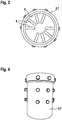
- the static mixing tools 8 are presently pin-shaped and extend from an inner circumferential surface 9 of the mixing tube 2 radially inward (see FIG. 3 ).
- the mixing tools 8 are arranged distributed substantially uniformly over the circumference of the mixing tube 2.
- the arrangement in the axial direction takes place here in three rows, which are arranged at the same distance from each other (see FIG. 4 ).
- the paddle-shaped mixing tools 5 of the shaft 4 cooperating with the static mixing tools 8 extend radially outwards, so that they engage in the interstices of the axially spaced rows of the static mixing tools 8.
- the paddle-shaped mixing tools 5 interacting with the static mixing tools 8 are arranged on a section 11 of the shaft 4, to which upstream of a section 12 connects, which is designed as a hollow shaft.
- the hollow shaft is formed from two brackets 13 which project radially outwards and on which paddle-shaped mixing tools 6 are arranged which extend radially inwards from the brackets 13.
- the section 12 comes to lie in the region of the connections 3 for a Anmach gallkeit.
- the section 12 is further followed by a section 10, which is designed in the manner of a mixing and / or screw conveyor and whose primary object is to promote the dry building material from the hopper 1 in the direction of the mixing tools 5, 6 and 8.
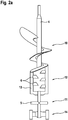
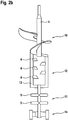
- sections 10, 11 and 12 may be chosen differently depending on the sensitivity of the dry building material to be applied. Exemplary embodiments are shown in FIGS FIGS. 2a and 2 B shown.
- a portion 14 which allows the connection of the shaft 4 to a shaft (not shown) of the delivery unit 15, so that the shaft 4 and the delivery unit 15 are drivable via a common electric motor.
- the section 14 is present anchor-shaped.
- the delivery unit 15 has a connection 16 for a discharge (not shown), in particular for a hose line of the discharge on. Via the hose line the dressed dry building material can be fed to a spray nozzle, which enables the machine discharge or application of the mass onto a surface.
Landscapes
- Chemical & Material Sciences (AREA)
- Chemical Kinetics & Catalysis (AREA)
- Engineering & Computer Science (AREA)
- Mechanical Engineering (AREA)
- Structural Engineering (AREA)
- Preparation Of Clay, And Manufacture Of Mixtures Containing Clay Or Cement (AREA)
Description
- Die Erfindung betrifft eine Vorrichtung zum Anmachen schwer benetzbarer Trockenbaustoffe, insbesondere einer Aerogel-Partikel enthaltenden Dämmputzzusammensetzung, mit den Merkmalen des Oberbegriffs des Anspruchs 1.
- Es gibt eine Vielzahl von Trockenbaustoffen, beispielsweise solche, die der Herstellung von Putz- oder Mörtelmassen dienen. Diese werden regelmäßig in Säcken oder Silos auf der Baustelle vorgehalten und erst kurz vor ihrer Verarbeitung durch Zugabe einer Anmachflüssigkeit, insbesondere Wasser, angemacht, d. h. gebrauchsfertig gemacht. Hierbei finden oftmals Vorrichtungen Einsatz, die auch als Putzmaschinen oder Mörtelmischpumpen bezeichnet werden.
- Aus der
DE 20 2006 016 925 U1 geht beispielhaft eine Mischvorrichtung für fließfähige Materialien hervor, die eine Zuführzone zum Zuführen wenigstens eines Ausgangsmaterials und eine sich hieran anschließende Mischzone zum Mischen des wenigstens einen Ausgangsmaterials mit einer Anmachflüssigkeit, insbesondere Wasser, besitzt. Die Mischzone umfasst ein äußeres und ein inneres Mischzonenrohr, mit einer hierin angeordneten, drehbaren Mischwelle, wobei das innere Mischzonenrohr zum Reinigen herausnehmbar im äußeren Mischzonenrohr gehalten ist. - Der
DE 2 218 418 A1 ist eine Misch- und Spritzvorrichtung für plastisches und körniges Gut zu entnehmen, die eine hohlzylindrische Mischkammer umfasst. In der Mischkammer ist eine Mischwelle mit radialen in mehreren Reihen und im Abstand übereinander angeordneten Rührstäben aufgenommen, die zwischen feststehenden Rührstäben umlaufen, die an der Innenfläche der Mischkammer angeordnet sind. - Aus der
DE 298 15 909 U1 ist ein Durchlaufmischer für Baustoffmischungen bekannt, der ein Mischrohr mit einer hierin aufgenommenen Mischerwelle und zumindest ein am Mischrohr abstützbares, in Betriebsstellung in den Mischraum vorspringenden Einsatzteil aufweist, das radial zur Mischerwelle ausgerichtet ist, - Der
DE 20 2007 015 262 U1 ist ferner eine Misch- und Fördereinrichtung für Mörtel zu entnehmen, die im Bereich einer Auslassöffnung eine Anschlussvorrichtung für Zusatzaggregate umfasst, so dass wahlweise kein, ein oder mehrere aufeinander abgestimmte Zusatzaggregate anbringbar sind. - Eine weitere Vorrichtung zum Anmachen eines trockenen oder rieselfähigen Baustoffs, insbesondere von Gips, der beim Anmachen zur Klümpchenbildung neigt, ist in der
DE 20 2008 016 904 U1 offenbart. Die Vorrichtung umfasst einen Behälter zur Aufnahme des Baustoffs und wenigstens ein in einer Mischkammer angeordnetes Mischwerkzeug. Der Behälter weist an seinem unteren Ende einen Auslass auf, der zu einem Eintritt in die Mischkammer führt bzw. den Eintritt der Mischkammer bildet. Um einer Klümpchenbildung entgegen zu wirken, wird der Baustoff vor Eintritt in die Mischkammer aufgelockert oder fluidisiert. Die Auflockerung bzw. Fluidisierung des Baustoffs soll die Vermischung des Baustoffs mit einer Anmachflüssigkeit erleichtern, die dem Baustoff in der Mischkammer zugeführt wird. Nach dem Durchlaufen der Mischkammer und dem Vermischen mit der Anmachflüssigkeit wird der Baustoff über eine Schneckenpumpe einer Fortsetzung der Mischkammer zugeführt und dort einem Nachmischprozess unterzogen. Durch den Nachmischprozess sollen etwaige noch verbliebene Klümpchen oder unerwünschte Zusammenballungen des Baustoffs gänzlich zum Verschwinden gebracht werden. - Neben schwer benetzbaren Trockenbaustoffen, die zur Klümpchenbildung neigen, sind solche bekannt, die nicht ausreichend abriebfest und/oder empfindlich gegenüber Scherkräften sind. Beispielhaft können hier Aerogel-Partikel enthaltende Zusammensetzungen genannt werden, die insbesondere als Leichtfüllstoff in Dämmputzen Verwendung finden. Denn Aerogel-Partikel weisen aufgrund ihrer hohen Porosität eine besonders niedrige Wärmeleitfähigkeit auf. Die Verarbeitung Aerogel-Partikel enthaltender Zusammensetzungen in herkömmlichen Putzmaschinen oder Mörtelmischpumpen stellt sich jedoch als problematisch dar, da die hierin auf die Partikel wirkenden hohen Scherkräfte zu einer Zerkleinerung der enthaltenen Aerogel-Partikel und damit zu einer erhöhten Rohdichte der angemachten Zusammensetzung führen. Mit einer erhöhten Rohdichte geht ein Anstieg der Wärmeleitfähigkeit einher, so dass sich die Wärmedämmwerte eines hieraus hergestellten Dämmputzes deutlich verschlechtern. Versuche Dritter haben gezeigt, dass die Wärmeleitfähigkeit eines aerogelhaltigen Dämmputzes bei maschineller Applikation mittels einer marktüblichen Putzmaschine bei einem Druck von 8 bar etwa um den Faktor 2 erhöht wird. Die Vorteile eines aerogelhaltigen Dämmputzes wären damit zunichte gemacht.
- Ein weiterer Nachteil bei der Verarbeitung aerogelhaltiger Zusammensetzungen in herkömmlichen Putzmaschinen oder Mörtelmischpumpen ist in einem erhöhten Verschleiß zu sehen, der auf einen erhöhten Abrieb zurückzuführen ist. Besonders verschleißanfällig sind integrierte oder angeschlossene Förderaggregate, wie beispielsweise eine nachgeschaltete Schneckenpumpe, zum Austragen der angemachten Trockenbaustoffe. Einem erhöhten Verschleiß unterliegt insbesondere der Schneckenmantel.
- Der Erfindung liegt die Aufgabe zugrunde, eine Vorrichtung zum Anmachen schwer benetzbarer Trockenbaustoffe, insbesondere einer Aerogel-Partikel enthaltenden Dämmputzzusammensetzung, anzugeben, die eine schonende Verarbeitung der Trockenbaustoffe ermöglicht, so dass die vorstehend genannten Nachteile nicht auftreten.
- Zur Lösung der Aufgabe wird die Vorrichtung mit den Merkmalen des Anspruchs 1 vorgeschlagen. Vorteilhafte Weiterbildungen der Erfindung sind den Unteransprüchen zu entnehmen.
- Die zum Anmachen schwer benetzbarer Trockenbaustoffe, insbesondere einer Aerogel-Partikel enthaltenden Dämmputzzusammensetzung, vorgeschlagene Vorrichtung umfasst einen Einfülltrichter zum Einfüllen wenigstens eines Trockenbaustoffs und ein mit dem Einfülltrichter verbundenes ein- oder mehrteilig ausgebildetes Mischrohr, das wenigstens einen Anschluss für eine Anmachflüssigkeit, insbesondere für Wasser, besitzt. In dem Mischrohr ist eine über einen Elektromotor antreibbare Welle mit Mischwerkzeugen angeordnet. Dabei weist ein Teil oder Abschnitt des
Mischrohrs statische Mischwerkzeuge auf, die sich von einer Innenumfangsfläche des Mischrohrs nach radial innen erstrecken. - Die statischen Mischwerkzeuge beeinflussen den Stoffstrom im Mischrohr. Vorzugsweise teilen sie den Stoffstrom auf und führen ihn anschließend wieder zusammen, so dass eine Vermischung der Ausgangsstoffe über die Strömungsbewegung erreicht wird. Die statischen Mischwerkzeuge erlauben auf diese Weise eine besonders schonende Verarbeitung des Trockenbaustoffs, so dass eine Zerkleinerung der Aerogel-Partikel sowie ein damit einhergehender Anstieg der Rohdichte weitgehend verhindert werden. Zugleich wird eine gute Benetzung des Trockenbaustoffs mit der Anmachflüssigkeit erreicht.
- Die erfindungsgemäße Vorrichtung eignet sich aus den vorstehend genannten Gründen insbesondere für die Herstellung aerogelhaltiger Dämmputzzusammensetzungen. Darüber hinaus kann die erfindungsgemäße Vorrichtung zum Anmachen beliebiger Trockenbaustoffe eingesetzt werden. Denn die schonende Verarbeitung und zugleich gute Benetzung der Trockenbaustoffe mit einer Anmachflüssigkeit wirken sich allgemein als Vorteil aus. Ein weiterer Vorteil ist darin zu sehen, dass die Vorrichtung weniger verschleißbehaftet ist, was darauf zurückzuführen ist, dass der Abrieb verringert wird.
- Der Einsatz statischer Mischwerkzeuge schließt nicht aus, dass weitere Mischwerkezuge vorhanden sind, insbesondere vorgeschaltet sind. Die weiteren Mischwerkzeuge sind vorzugsweise dergestalt, dass sie ein erstes Aufmischen der Ausgangsstoffe ermöglichen, um deren Verarbeitungseigenschaften zu verbessern. Die statischen Mischwerkzeuge bewirken dann den eigentlichen Mischvorgang. Alternativ können die statischen Mischwerkzeuge als eine Art "Nachmischer" eingesetzt werden, um den Mischvorgang zu verlängern und auf schonende Art und Weise eine bessere Benetzung der Trockenbaustoffe mit der Anmachflüssigkeit zu erzielen.
- Bevorzugt sind die statischen Mischwerkzeuge als Stifte, Paddel und/oder Flügel ausgebildet. Insbesondere können die statischen Mischwerkzeuge eine Geometrie aufweisen, die zugleich eine Lenkung des Stoffstroms im Mischrohr bewirkt. Beispielsweise können die Paddel und/oder Flügel gegenüber einer Radialebene angestellt bzw. geneigt sein. Weiterhin bevorzugt sind die statischen Mischwerkzeuge in einer Reihe oder in mehreren Reihen über den Innenumfang des Mischrohrs verteilt angeordnet. Auf diese Weise wird eine gleichmäßige Vermischung der Ausgangsstoffe erreicht. Gemäss der vorliegenden Erfindung, weist die im Mischrohr angeordnete Welle Mischwerkzeuge auf, die sich von der Welle nach radial außen erstrecken und mit den statischen Mischwerkzeugen zusammenwirken. Die sich mit der Welle drehenden Mischwerkzeuge teilen den Stoffstrom im Mischrohr in einer weiteren Richtung, so dass die Vermischung der Ausgangsstoffe bzw. die Benetzung des Trockenbaustoffs mit der Anmachflüssigkeit verbessert wird. Die mit den statischen Mischwerkzeugen zusammenwirkenden Mischwerkzeuge sollten dabei dergestalt sein, dass weiterhin eine schonende Verarbeitung der Trockenbaustoffe gewährleistet ist.
- Bevorzugt sind die mit den statischen Mischwerkzeugen zusammenwirkenden Mischwerkzeuge der Welle als Stifte, Paddel und/oder Flügel ausgebildet, die in axialer Richtung versetzt zu den statischen Mischwerkzeugen angeordnet sind. Die Mischwerkzeuge der Welle greifen somit in die Zwischenräume der statischen Mischwerkzeuge ein. Die statischen und dynamischen Mischwerkzeuge berühren sich dabei nicht. Die Geometrie der dynamischen Mischwerkzeuge kann ebenfalls derart gewählt sein, dass sie eine Lenkung des Stoffstroms bewirken.
- Weiterhin bevorzugt ist der die statischen Mischwerkzeuge aufweisende Teil oder Abschnitt des Mischrohrs stromabwärts des Anschlusses für die Anmachflüssigkeit angeordnet. Die Angabe "stromabwärts" bezieht sich hierbei auf die Hauptströmungsrichtung des im Mischrohr aufgenommenen Stoffstroms. Dem Trockenbaustoff wird demnach zunächst die Anmachflüssigkeit zugegeben, anschließend wird die Vermischung des Trockenbaustoffs mit der Anmachflüssigkeit über die statischen Mischwerkzeuge bewirkt. Dies schließt nicht aus, dass den statischen Mischwerkzeugen weitere Werkzeuge zum Mischen und/oder Fördern vorgeschaltet sind, um beispielsweise ein erstes Aufmischen der zu vermischenden Ausgangsstoffe und/oder die Förderung des Stoffstroms in Richtung der statischen Mischwerkzeuge zu bewirken.
- Sofern weitere Werkzeuge zum Mischen und/oder Fördern vorgesehen sind, sind diese bevorzugt an der im Mischrohr aufgenommenen Welle angeordnet. Hierzu kann die Welle mehrteilig ausgebildet sein oder mehrere Abschnitte aufweisen, die jeweils unterschiedlich ausgestaltet sind. Im Falle einer mehrteiligen Ausbildung sind die mehreren Teile der Welle vorzugsweise derart wirkverbunden, dass sie gemeinsam über einen Elektromotor zu einer Drehbewegung antreibbar sind.
- Soweit nachfolgend von einem "Abschnitt" der Welle die Rede ist, umfasst dieser Begriff auch ein separates Teil der Welle, das mit wenigstens einem weiteren Wellenteil in der vorstehend genannten Weise wirkverbunden ist.
- Erfindungsgemäß umfasst die Welle einen Abschnitt, der als Misch- und/oder Förderschnecke ausgebildet ist. Dieser Wellenabschnitt ist stromaufwärts eines Abschnitts angeordnet, der die mit den statischen Mischwerkzeugen zusammenwirkenden Mischwerkzeuge aufweist. Der als Misch- und/oder Förderschnecke ausgebildete Wellenabschnitt dient demnach insbesondere dem Aufmischen und der Förderung des Trockenbaustoffs in Richtung der statischen Mischwerkzeuge. Idealerweise ist hierzu der als Misch- und/oder Förderschnecke ausgebildete Wellenabschnitt im Bereich des Einfülltrichters und/oder im Bereich des Anschlusses für eine Anmachflüssigkeit angeordnet.
- Ferner erfindungsgemäß umfasst die Welle einen Abschnitt, der als Hohlwelle ausgebildet ist. Der Abschnitt ist stromaufwärts eines Abschnitts angeordnet, der die mit den statischen Mischwerkzeugen zusammenwirkenden Mischwerkzeuge aufweist. Sofern die Welle zudem einen als Misch- und/oder Förderschnecke ausgebildeten Abschnitt besitzt, ist weiterhin vorzugsweise der als Hohlwelle ausgebildete Abschnitt stromabwärts des als Misch- und/oder Förderschnecke ausgebildeten Abschnitts angeordnet. Der als Hohlwelle ausgebildete Abschnitt bildet demnach bevorzugt einen mittleren Wellenabschnitt aus, an den beidseits wenigstens ein weiterer Wellenabschnitt angrenzt. Die vorrangige Aufgabe des als Hohlwelle ausgebildeten Wellenabschnitts besteht insbesondere darin, eine Umlenkung des Stoffstroms zu bewirken.
- Bevorzugt ist der als Hohlwelle ausgebildete Abschnitt aus mehreren, vorzugsweise zwei, in gleichem Winkelabstand zueinander angeordneten Bügeln gebildet. Weiterhin bevorzugt teilt sich die Welle in wenigstens zwei Bügel auf, die nach radial außen gerückt sind und somit einen zentralen Hohlraum definieren. Bei einer Drehbewegung der Welle bewirken die Bügel eine Umlenkung des Stoffstroms von radial außen nach radial innen.
- Als weiterbildende Maßnahme wird vorgeschlagen, dass die Bügel Mischwerkzeuge besitzen, die sich von den Bügeln nach radial innen erstrecken. Die Mischwerkzeuge können insbesondere als Stifte, Paddel und/oder Flügel ausgebildet sein. Auf diese Weise wird ein verbessertes Aufmischen der Ausgangsstoffe erreicht.
- Des Weiteren erfindungsgemäß umfasst die Welle einen Abschnitt für den Anschluss eines Förderaggregats, insbesondere einer Schneckenpumpe. Der Anschlussabschnitt ist stromabwärts eines Abschnitts angeordnet, der die mit den statischen Mischwerkzeugen zusammenwirkenden Mischwerkzeuge aufweist. Vorzugsweise ist im Bereich des Anschlusses die Welle derart mit einer Welle des Förderaggregats
verbindbar, dass die Welle und das Förderaggregat gemeinsam über einen Elektromotor antreibbar sind. - Indem der Wellenabschnitt für den Anschluss eines Förderaggregats stromabwärts des Abschnitts angeordnet ist, der die mit den statischen Mischwerkzeugen zusammenwirkenden Mischwerkzeuge aufweist, ist eine ausreichende Benetzung des angemachten Trockenbaustoffs mit Anmachflüssigkeit vor Eintritt in das Förderaggregat sichergestellt. Auf diese Weise wird der Verschleiß an den Werkzeugoberflächen, insbesondere am Schneckenmantel eines als Schneckenpumpe ausgebildeten Förderaggregats, gemindert.
- In Weiterbildung der Erfindung wird vorgeschlagen, dass das Förderaggregat mit einer Austragseinrichtung verbunden oder verbindbar ist, um den angemachten Trockenbaustoff, vorzugsweise mittels Spritzen, auszutragen. Hierzu kann die Austragseinrichtung eine Spritzdüse umfassen. In Verbindung mit einer solchen Austragseinrichtung kann die vorgeschlagene erfindungsgemäße Vorrichtung sowohl zum Anmachen eines Trockenbaustoffs, als auch zum Austragen des angemachten Trockenbaustoffs eingesetzt werden.
- Bevorzugte Ausführungsformen der Erfindung werden anhand der beigefügten Zeichnungen nachfolgend näher beschrieben. Diese zeigen:
-
Fig. 1 eine Seitenansicht einer erfindungsgemäßen Vorrichtung, -
Fig. 2a ,b jeweils eine Seitenansicht einer Welle einer erfindungsgemäßen Vorrichtung, -
Fig. 3 eine Draufsicht auf ein Mischrohrteil einer erfindungsgemäßen Vorrichtung und -
Fig. 4 eine Seitenansicht des Mischrohrteils derFig. 3 . - Die in der
Figur 1 dargestellte erfindungsgemäße Vorrichtung zum Anmachen schwer benetzbarer Trockenbaustoffe umfasst ein mehrteiliges Mischrohr 2, das senkrecht auf einem fahrbaren Gestell 17 angeordnet ist. Das Mischrohr 2 weist an seinem oberen Ende einen Einfülltrichter 1 auf, der von einem seitlich neben dem Mischrohr 2 auf dem Gestell 17 angeordneten Behälter 18 gespeist wird. Der Behälter 18 enthält den anzumachenden Trockenbaustoff. Die Zugabe einer Anmachflüssigkeit erfolgt über einen Anschluss 3, der in einem Außenumfangsbereich des Mischrohrs 2 angeordnet ist. Vorliegend sind untereinander liegend zwei solcher Anschlüsse 3 vorgesehen. - Im Mischrohr 2 ist eine über einen Elektromotor (nicht dargestellt) antreibbare Welle 4 angeordnet, die Mischwerkzeuge 5, 6 besitzt (siehe
Figuren 2a und2b ). Die Mischwerkzeuge 5 wirken mit statischen Mischwerkzeugen 8 zusammen, die in einem Teil 7 des Mischrohres 2 angeordnet sind, das vorliegend von unten angeflanscht ist und mit einem Förderaggregat 15 in Form einer Schneckenpumpe verbunden ist (sieheFigur 1 ). Die statischen Mischwerkzeuge 8 sind vorliegend stiftförmig ausgebildet und erstrecken sich von einer Innenumfangsfläche 9 des Mischrohrs 2 nach radial innen (sieheFigur 3 ). Die Mischwerkzeuge 8 sind über den Umfang des Mischrohrs 2 im Wesentlichen gleichmäßig verteilt angeordnet. Die Anordnung in axialer Richtung erfolgt vorliegend in drei Reihen, die im gleichen Abstand zueinander angeordnet sind (sieheFigur 4 ). Wie in derFigur 2b dargestellt erstrecken sich die mit den statischen Mischwerkzeugen 8 zusammenwirkenden paddelförmigen Mischwerkzeuge 5 der Welle 4 nach radial außen, so dass sie in die Zwischenräume der axial beabstandeten Reihen der statischen Mischwerkzeuge 8 greifen. - Die mit den statischen Mischwerkzeugen 8 zusammenwirkenden paddelförmigen Mischwerkzeuge 5 sind auf einem Abschnitt 11 der Welle 4 angeordnet, an den sich stromaufwärts ein Abschnitt 12 anschließt, der als Hohlwelle ausgebildet ist. Die Hohlwelle wird vorliegend aus zwei nach radial außen verspringenden Bügeln 13 gebildet, an denen paddelförmige Mischwerkzeuge 6 angeordnet sind, die sich von den Bügeln 13 nach radial innen erstrecken. Der Abschnitt 12 kommt im Bereich der Anschlüsse 3 für eine Anmachflüssigkeit zu liegen. An den Abschnitt 12 schließt sich ferner ein Abschnitt 10 an, der nach Art einer Misch- und/oder Förderschnecke ausgebildet ist und dessen vorrangige Aufgabe es ist, den Trockenbaustoff vom Einfülltrichter 1 in Richtung der Mischwerkzeuge 5, 6 und 8 zu fördern.
- Die jeweiligen Längen der Abschnitte 10, 11 und 12 können in Abhängigkeit von der Empfindlichkeit des anzumachenden Trockenbaustoffs unterschiedlich gewählt sein. Beispielhafte Ausführungsformen sind in den
Figuren 2a und2b dargestellt. - Beiden Ausführungsformen gemein ist ein Abschnitt 14, der den Anschluss der Welle 4 an eine Welle (nicht dargestellt) des Förderaggregats 15 ermöglicht, so dass die Welle 4 und das Förderaggregat 15 über einen gemeinsamen Elektromotor antreibbar sind. Der Abschnitt 14 ist vorliegend ankerförmig ausgebildet.
- Wie der
Figur 1 zu entnehmen ist, weist das Förderaggregat 15 einen Anschluss 16 für eine Austragseinrichtung (nicht dargestellt), insbesondere für eine Schlauchleitung der Austragseinrichtung, auf. Über die Schlauchleitung kann der angemachte Trockenbaustoff einer Spritzdüse zugeführt werden, die den maschinellen Austrag bzw. Auftrag der Masse auf eine Fläche ermöglicht. -
- 1 Einfülltrichter
- 2 Mischrohr
- 3 Anschluss für eine Anmachflüssigkeit
- 4 Welle
- 5 Mischwerkzeug
- 6 Mischwerkzeug
- 7 Teil des Mischrohrs
- 8 statisches Mischwerkzeug
- 9 Innenumfangsfläche
- 10 Abschnitt der Welle
- 11 Abschnitt der Welle
- 12 Abschnitt der Welle
- 13 Bügel
- 14 Abschnitt der Welle
- 15 Förderaggregat
- 16 Anschluss für eine Austragseinrichtung
- 17 Gestell
- 18 Behälter
Claims (8)
- Vorrichtung zum Anmachen schwer benetzbarer Trockenbaustoffe, insbesondere einer Aerogel-Partikel enthaltenden Dämmputzzusammensetzung, umfassend einen Einfülltrichter (1) zum Einfüllen wenigstens eines Trockenbaustoffs und ein mit dem Einfülltrichter verbundenes ein- oder mehrteilig ausgebildetes Mischrohr (2), das wenigstens einen Anschluss (3) für eine Anmachflüssigkeit, insbesondere für Wasser, besitzt, wobei ein Teil (7) oder Abschnitt des Mischrohrs (2) statische Mischwerkzeuge (8) aufweist, die sich von einer Innenumfangsfläche (9) des Mischrohrs (2) nach radial innen erstrecken und wobei in dem Mischrohr (2) eine über einen Elektromotor antreibbare Welle (4) angeordnet ist, die Mischwerkzeuge (5) aufweist, die sich von der Welle (4) nach radial außen erstrecken und mit den statischen Mischwerkzeugen (8) zusammenwirken,
dadurch gekennzeichnet, dass- die Welle (4) einen Abschnitt (10) umfasst, der als Misch- und/oder Förderschnecke ausgebildet und stromaufwärts eines Abschnitts (11) angeordnet ist, der die mit den statischen Mischwerkzeugen (8) zusammenwirkenden Mischwerkzeuge (5) aufweist,- die Welle (4) einen Abschnitt (14) für den Anschluss eines Förderaggregats (15), insbesondere einer Schneckenpumpe, umfasst, der stromabwärts des Abschnitts (11) angeordnet ist, und- die Welle (4) einen Abschnitt (12) umfasst, der als Hohlwelle ausgebildet ist und stromaufwärts des Abschnitts (11) angeordnet ist, der die mit den statischen Mischwerkzeugen (8) zusammenwirkenden Mischwerkzeuge (5) aufweist. - Vorrichtung nach Anspruch 1,
dadurch gekennzeichnet, dass die statischen Mischwerkzeuge (8) als Stifte, Paddel und/oder Flügel ausgebildet sind, die vorzugsweise in einer oder mehreren Reihen über den Innenumfang des Mischrohrs (2) verteilt angeordnet sind. - Vorrichtung nach einem der vorhergehenden Ansprüche,
dadurch gekennzeichnet, dass die mit den statischen Mischwerkzeugen (8) zusammenwirkenden Mischwerkzeuge (5) der Welle (4) als Stifte, Paddel und/oder Flügel ausgebildet sind, die in axialer Richtung versetzt zu den statischen Mischwerkzeugen (8) angeordnet sind. - Vorrichtung nach einem der vorhergehenden Ansprüche,
dadurch gekennzeichnet, dass der die statischen Mischwerkzeuge (8) aufweisende Teil (7) oder Abschnitt des Mischrohrs (2) stromabwärts des Anschlusses (3) für die Anmachflüssigkeit angeordnet ist. - Vorrichtung nach einem der vorhergehenden Ansprüche,
dadurch gekennzeichnet, dass der als Hohlwelle ausgebildete Abschnitt (12) stromabwärts des als Misch- und/oder Förderschnecke ausgebildeten Abschnitts (10) angeordnet ist. - Vorrichtung nach Anspruch 5,
dadurch gekennzeichnet, dass der als Hohlwelle ausgebildete Abschnitt (12) aus mehreren, vorzugsweise zwei, in gleichem Winkelabstand zueinander angeordneten Bügeln (13) gebildet ist. - Vorrichtung nach Anspruch 6,
dadurch gekennzeichnet, dass die Bügel (13) Mischwerkzeuge (6) besitzen, die sich von den Bügeln (13) nach radial innen erstrecken und/oder als Stifte, Paddel und/oder Flügel ausgebildet sind. - Vorrichtung nach einem der vorhergehenden Ansprüche,
dadurch gekennzeichnet, dass das Förderaggregat (15) mit einer Austragseinrichtung verbunden oder verbindbar ist, um den angemachten Trockenbaustoff, vorzugsweise mittels Spritzen, auszutragen.
Applications Claiming Priority (1)
| Application Number | Priority Date | Filing Date | Title |
|---|---|---|---|
| DE102014005405.5A DE102014005405A1 (de) | 2014-04-14 | 2014-04-14 | Vorrichtung zum Anmachen schwer benetzbarer Trockenbaustoffe |
Publications (2)
| Publication Number | Publication Date |
|---|---|
| EP2933079A1 EP2933079A1 (de) | 2015-10-21 |
| EP2933079B1 true EP2933079B1 (de) | 2018-08-22 |
Family
ID=52807587
Family Applications (1)
| Application Number | Title | Priority Date | Filing Date |
|---|---|---|---|
| EP15160386.7A Active EP2933079B1 (de) | 2014-04-14 | 2015-03-23 | Vorrichtung zum anmachen schwer benetzbarer trockenbaustoffe |
Country Status (2)
| Country | Link |
|---|---|
| EP (1) | EP2933079B1 (de) |
| DE (1) | DE102014005405A1 (de) |
Citations (10)
| Publication number | Priority date | Publication date | Assignee | Title |
|---|---|---|---|---|
| DE2218418A1 (de) | 1972-04-17 | 1973-10-31 | Wilhelm Fleissner | Misch- und spritzvorrichtung fuer plastisches und koerniges gut |
| DE2340246A1 (de) | 1973-08-09 | 1974-09-19 | Karl Dipl-Ing Schlecht | Kontinuierliche mischpumpe |
| DE3142053A1 (de) | 1980-10-31 | 1983-05-05 | Mathis System-Technik Gmbh, 7801 Merdingen | "verfahren und vorrichtung zum kontinuierlichen anmachen von moertel, putz, beton o.dgl. baustoff oder material" |
| DE3532722A1 (de) | 1985-09-13 | 1987-03-26 | Heidelberger Zement Ag | Vorrichtung und verfahren zur kontinuierlichen bereitstellung von hydraulisch abbindender masse |
| DE69207440T2 (de) | 1991-01-22 | 1996-08-29 | Omniplastic Sa | Verfahren und Vorrichtung zum kontinuierlichen Zubereiten, Überführen und Einbringen einer flüssigen, wässrigen, mineralischen putzenden Suspension |
| EP1000718A2 (de) | 1998-11-05 | 2000-05-17 | Wildgruber Baustoffwerke GmbH & Co. KG | Mischer zum Herstellen pumpfähiger Putzmassen |
| DE202004020257U1 (de) | 2004-12-28 | 2006-02-09 | Knauf Pft Gmbh & Co.Kg | Mischvorrichtung |
| DE202007015262U1 (de) * | 2006-11-02 | 2008-02-28 | Gerster, Karlheinz | Misch- und Fördervorrichtung für Mörtel |
| DE102006049171A1 (de) | 2006-10-18 | 2008-04-30 | Werner Dutschmann | Einrichtung zum kontinuierlichen und intensiven Mischen von Trockenmörtel |
| DE202008016904U1 (de) | 2008-12-19 | 2009-03-05 | M-Tec Mathis Technik Gmbh | Vorrichtung zum Anmachen eines Baustoffs, beispielsweise von Gips |
Family Cites Families (5)
| Publication number | Priority date | Publication date | Assignee | Title |
|---|---|---|---|---|
| DE3174819D1 (en) * | 1980-10-31 | 1986-07-17 | Mathis Systemtechnik Gmbh | Process and apparatus for the continuous preparation of mortar, plaster or the like building material |
| DE29815909U1 (de) * | 1998-09-04 | 1998-12-03 | INOTEC Maschinenbau GmbH, 49838 Wettrup | Durchlaufmischer für Baustoffmischungen |
| DE10211331B4 (de) * | 2002-03-14 | 2006-02-02 | Sto Ag | Verfahren zum Herstellen einer aerogelhaltigen Dämmschicht auf einer Außenwand eines Gebäudes |
| DE202006016925U1 (de) | 2006-11-02 | 2007-12-06 | Knauf Pft Gmbh & Co.Kg | Mischvorrichtung für fließfähige Materialien, insbesondere Baustoffmischungen |
| ITNA20080068A1 (it) * | 2008-11-28 | 2010-05-28 | Gerardina Ferraro | Macchina per la miscelazione in continuo di agglomerati in pietra composita. |
-
2014
- 2014-04-14 DE DE102014005405.5A patent/DE102014005405A1/de not_active Withdrawn
-
2015
- 2015-03-23 EP EP15160386.7A patent/EP2933079B1/de active Active
Patent Citations (11)
| Publication number | Priority date | Publication date | Assignee | Title |
|---|---|---|---|---|
| DE2218418A1 (de) | 1972-04-17 | 1973-10-31 | Wilhelm Fleissner | Misch- und spritzvorrichtung fuer plastisches und koerniges gut |
| DE2340246A1 (de) | 1973-08-09 | 1974-09-19 | Karl Dipl-Ing Schlecht | Kontinuierliche mischpumpe |
| DE3142053A1 (de) | 1980-10-31 | 1983-05-05 | Mathis System-Technik Gmbh, 7801 Merdingen | "verfahren und vorrichtung zum kontinuierlichen anmachen von moertel, putz, beton o.dgl. baustoff oder material" |
| DE3532722A1 (de) | 1985-09-13 | 1987-03-26 | Heidelberger Zement Ag | Vorrichtung und verfahren zur kontinuierlichen bereitstellung von hydraulisch abbindender masse |
| DE3546501A1 (de) | 1985-09-13 | 1987-04-23 | Heidelberger Zement Ag | Vorrichtung zur kontinuierlichen bereitstellung von hydraulisch abbindender masse |
| DE69207440T2 (de) | 1991-01-22 | 1996-08-29 | Omniplastic Sa | Verfahren und Vorrichtung zum kontinuierlichen Zubereiten, Überführen und Einbringen einer flüssigen, wässrigen, mineralischen putzenden Suspension |
| EP1000718A2 (de) | 1998-11-05 | 2000-05-17 | Wildgruber Baustoffwerke GmbH & Co. KG | Mischer zum Herstellen pumpfähiger Putzmassen |
| DE202004020257U1 (de) | 2004-12-28 | 2006-02-09 | Knauf Pft Gmbh & Co.Kg | Mischvorrichtung |
| DE102006049171A1 (de) | 2006-10-18 | 2008-04-30 | Werner Dutschmann | Einrichtung zum kontinuierlichen und intensiven Mischen von Trockenmörtel |
| DE202007015262U1 (de) * | 2006-11-02 | 2008-02-28 | Gerster, Karlheinz | Misch- und Fördervorrichtung für Mörtel |
| DE202008016904U1 (de) | 2008-12-19 | 2009-03-05 | M-Tec Mathis Technik Gmbh | Vorrichtung zum Anmachen eines Baustoffs, beispielsweise von Gips |
Also Published As
| Publication number | Publication date |
|---|---|
| EP2933079A1 (de) | 2015-10-21 |
| DE102014005405A1 (de) | 2015-10-15 |
Similar Documents
| Publication | Publication Date | Title |
|---|---|---|
| EP1914056B1 (de) | Einrichtung zum kontinuierlichen und intensiven Mischen von Trockenmörtel | |
| DE3532722C2 (de) | ||
| AT515881B1 (de) | Sequentielle Durchlaufmischanlage | |
| DE2337129A1 (de) | Vorrichtung zum bereiten und abgeben von faser-beton-gemischen | |
| EP2722103A2 (de) | Zwangsmischer mit Selbstreinigungsfunktion und Verwendung von Lufteinlässen hierfür | |
| EP1932427B1 (de) | Vorrichtung und Verfahren zum Einarbeiten von Flüssigkeit in schütt- oder rieselfähige Trockenstoffe | |
| DE19629945C2 (de) | Mischvorrichtung zum Vermischen eines pulverförmigen und/oder körnigen Feststoffes mit einer Flüssigkeit | |
| CH652789A5 (de) | Vorrichtung zum mischen und spritzen von nassbeton. | |
| DE19542663A1 (de) | Mischvorrichtung | |
| DE2543379A1 (de) | Vorrichtung zur kontinuierlichen herstellung von angemachtem moertel | |
| EP2558367B1 (de) | Vorrichtung zum fördern von material mittels einer horizontalzellenradschleuse | |
| DE2166509A1 (de) | Anlage zum versorgen einer betonspritzmaschine mit nassbeton | |
| DE2425532A1 (de) | Vorrichtung und verfahren zum dosierten austrag stark backender bzw. agglomerationsfreudiger und schwer fluidisierbarer pulver aus behaeltern | |
| EP2933079B1 (de) | Vorrichtung zum anmachen schwer benetzbarer trockenbaustoffe | |
| EP0592793B1 (de) | Verfahren und Vorrichtung zum Auftragen eines Mörtels oder Betons durch Spritzen | |
| DE2130257A1 (de) | Verfahren und Vorrichtung zum pneumatischen Aufbringen eines dickfluessigen Materials | |
| EP0864408B1 (de) | Vorrichtung zum kontinuierlichen Anmachen von Schüttgut- oder Baustoffmischungen | |
| EP0574728B1 (de) | Herstellung und Förderung eines Baustoffgemisches | |
| CH507138A (de) | Einrichtung zum Fördern und Dosieren von pastösen, klebrigen und rieselfähigen Materialien | |
| EP0587058A1 (de) | Füllvorrichtung für insbesondere Ventilsäcke | |
| DE3929729C2 (de) | Vorrichtung zum Anteigen eines Trockenmörtels | |
| DE202015101125U1 (de) | Mischkessel mit Verschleißschutz | |
| DE19812154A1 (de) | Vorrichtung zum Mischen und Fördern von Stoffgemischen | |
| AT523366B1 (de) | Mischer einer Durchlaufmischanlage | |
| CH712621A2 (de) | Mischer mit Einfach-Befüllung und kontinuierlicher Produktausgabe. |
Legal Events
| Date | Code | Title | Description |
|---|---|---|---|
| PUAI | Public reference made under article 153(3) epc to a published international application that has entered the european phase |
Free format text: ORIGINAL CODE: 0009012 |
|
| AK | Designated contracting states |
Kind code of ref document: A1 Designated state(s): AL AT BE BG CH CY CZ DE DK EE ES FI FR GB GR HR HU IE IS IT LI LT LU LV MC MK MT NL NO PL PT RO RS SE SI SK SM TR |
|
| AX | Request for extension of the european patent |
Extension state: BA ME |
|
| 17P | Request for examination filed |
Effective date: 20151203 |
|
| RBV | Designated contracting states (corrected) |
Designated state(s): AL AT BE BG CH CY CZ DE DK EE ES FI FR GB GR HR HU IE IS IT LI LT LU LV MC MK MT NL NO PL PT RO RS SE SI SK SM TR |
|
| 17Q | First examination report despatched |
Effective date: 20160406 |
|
| STAA | Information on the status of an ep patent application or granted ep patent |
Free format text: STATUS: EXAMINATION IS IN PROGRESS |
|
| GRAP | Despatch of communication of intention to grant a patent |
Free format text: ORIGINAL CODE: EPIDOSNIGR1 |
|
| STAA | Information on the status of an ep patent application or granted ep patent |
Free format text: STATUS: GRANT OF PATENT IS INTENDED |
|
| GRAJ | Information related to disapproval of communication of intention to grant by the applicant or resumption of examination proceedings by the epo deleted |
Free format text: ORIGINAL CODE: EPIDOSDIGR1 |
|
| STAA | Information on the status of an ep patent application or granted ep patent |
Free format text: STATUS: EXAMINATION IS IN PROGRESS |
|
| INTG | Intention to grant announced |
Effective date: 20180403 |
|
| INTC | Intention to grant announced (deleted) | ||
| GRAP | Despatch of communication of intention to grant a patent |
Free format text: ORIGINAL CODE: EPIDOSNIGR1 |
|
| STAA | Information on the status of an ep patent application or granted ep patent |
Free format text: STATUS: GRANT OF PATENT IS INTENDED |
|
| INTG | Intention to grant announced |
Effective date: 20180606 |
|
| GRAS | Grant fee paid |
Free format text: ORIGINAL CODE: EPIDOSNIGR3 |
|
| GRAA | (expected) grant |
Free format text: ORIGINAL CODE: 0009210 |
|
| STAA | Information on the status of an ep patent application or granted ep patent |
Free format text: STATUS: THE PATENT HAS BEEN GRANTED |
|
| AK | Designated contracting states |
Kind code of ref document: B1 Designated state(s): AL AT BE BG CH CY CZ DE DK EE ES FI FR GB GR HR HU IE IS IT LI LT LU LV MC MK MT NL NO PL PT RO RS SE SI SK SM TR |
|
| REG | Reference to a national code |
Ref country code: GB Ref legal event code: FG4D Free format text: NOT ENGLISH |
|
| REG | Reference to a national code |
Ref country code: CH Ref legal event code: EP |
|
| REG | Reference to a national code |
Ref country code: AT Ref legal event code: REF Ref document number: 1031930 Country of ref document: AT Kind code of ref document: T Effective date: 20180915 |
|
| REG | Reference to a national code |
Ref country code: IE Ref legal event code: FG4D Free format text: LANGUAGE OF EP DOCUMENT: GERMAN |
|
| REG | Reference to a national code |
Ref country code: DE Ref legal event code: R096 Ref document number: 502015005528 Country of ref document: DE |
|
| REG | Reference to a national code |
Ref country code: CH Ref legal event code: NV Representative=s name: GOTTSCHALK MAIWALD PATENTANWALTS- UND RECHTSAN, CH |
|
| REG | Reference to a national code |
Ref country code: NL Ref legal event code: MP Effective date: 20180822 |
|
| REG | Reference to a national code |
Ref country code: LT Ref legal event code: MG4D |
|
| PG25 | Lapsed in a contracting state [announced via postgrant information from national office to epo] |
Ref country code: NL Free format text: LAPSE BECAUSE OF FAILURE TO SUBMIT A TRANSLATION OF THE DESCRIPTION OR TO PAY THE FEE WITHIN THE PRESCRIBED TIME-LIMIT Effective date: 20180822 Ref country code: BG Free format text: LAPSE BECAUSE OF FAILURE TO SUBMIT A TRANSLATION OF THE DESCRIPTION OR TO PAY THE FEE WITHIN THE PRESCRIBED TIME-LIMIT Effective date: 20181122 Ref country code: LT Free format text: LAPSE BECAUSE OF FAILURE TO SUBMIT A TRANSLATION OF THE DESCRIPTION OR TO PAY THE FEE WITHIN THE PRESCRIBED TIME-LIMIT Effective date: 20180822 Ref country code: RS Free format text: LAPSE BECAUSE OF FAILURE TO SUBMIT A TRANSLATION OF THE DESCRIPTION OR TO PAY THE FEE WITHIN THE PRESCRIBED TIME-LIMIT Effective date: 20180822 Ref country code: IS Free format text: LAPSE BECAUSE OF FAILURE TO SUBMIT A TRANSLATION OF THE DESCRIPTION OR TO PAY THE FEE WITHIN THE PRESCRIBED TIME-LIMIT Effective date: 20181222 Ref country code: GR Free format text: LAPSE BECAUSE OF FAILURE TO SUBMIT A TRANSLATION OF THE DESCRIPTION OR TO PAY THE FEE WITHIN THE PRESCRIBED TIME-LIMIT Effective date: 20181123 Ref country code: NO Free format text: LAPSE BECAUSE OF FAILURE TO SUBMIT A TRANSLATION OF THE DESCRIPTION OR TO PAY THE FEE WITHIN THE PRESCRIBED TIME-LIMIT Effective date: 20181122 Ref country code: FI Free format text: LAPSE BECAUSE OF FAILURE TO SUBMIT A TRANSLATION OF THE DESCRIPTION OR TO PAY THE FEE WITHIN THE PRESCRIBED TIME-LIMIT Effective date: 20180822 Ref country code: SE Free format text: LAPSE BECAUSE OF FAILURE TO SUBMIT A TRANSLATION OF THE DESCRIPTION OR TO PAY THE FEE WITHIN THE PRESCRIBED TIME-LIMIT Effective date: 20180822 |
|
| PG25 | Lapsed in a contracting state [announced via postgrant information from national office to epo] |
Ref country code: AL Free format text: LAPSE BECAUSE OF FAILURE TO SUBMIT A TRANSLATION OF THE DESCRIPTION OR TO PAY THE FEE WITHIN THE PRESCRIBED TIME-LIMIT Effective date: 20180822 Ref country code: HR Free format text: LAPSE BECAUSE OF FAILURE TO SUBMIT A TRANSLATION OF THE DESCRIPTION OR TO PAY THE FEE WITHIN THE PRESCRIBED TIME-LIMIT Effective date: 20180822 Ref country code: LV Free format text: LAPSE BECAUSE OF FAILURE TO SUBMIT A TRANSLATION OF THE DESCRIPTION OR TO PAY THE FEE WITHIN THE PRESCRIBED TIME-LIMIT Effective date: 20180822 |
|
| PG25 | Lapsed in a contracting state [announced via postgrant information from national office to epo] |
Ref country code: PL Free format text: LAPSE BECAUSE OF FAILURE TO SUBMIT A TRANSLATION OF THE DESCRIPTION OR TO PAY THE FEE WITHIN THE PRESCRIBED TIME-LIMIT Effective date: 20180822 Ref country code: EE Free format text: LAPSE BECAUSE OF FAILURE TO SUBMIT A TRANSLATION OF THE DESCRIPTION OR TO PAY THE FEE WITHIN THE PRESCRIBED TIME-LIMIT Effective date: 20180822 Ref country code: IT Free format text: LAPSE BECAUSE OF FAILURE TO SUBMIT A TRANSLATION OF THE DESCRIPTION OR TO PAY THE FEE WITHIN THE PRESCRIBED TIME-LIMIT Effective date: 20180822 Ref country code: RO Free format text: LAPSE BECAUSE OF FAILURE TO SUBMIT A TRANSLATION OF THE DESCRIPTION OR TO PAY THE FEE WITHIN THE PRESCRIBED TIME-LIMIT Effective date: 20180822 Ref country code: ES Free format text: LAPSE BECAUSE OF FAILURE TO SUBMIT A TRANSLATION OF THE DESCRIPTION OR TO PAY THE FEE WITHIN THE PRESCRIBED TIME-LIMIT Effective date: 20180822 Ref country code: CZ Free format text: LAPSE BECAUSE OF FAILURE TO SUBMIT A TRANSLATION OF THE DESCRIPTION OR TO PAY THE FEE WITHIN THE PRESCRIBED TIME-LIMIT Effective date: 20180822 |
|
| REG | Reference to a national code |
Ref country code: DE Ref legal event code: R026 Ref document number: 502015005528 Country of ref document: DE |
|
| PLAZ | Examination of admissibility of opposition: despatch of communication + time limit |
Free format text: ORIGINAL CODE: EPIDOSNOPE2 |
|
| PG25 | Lapsed in a contracting state [announced via postgrant information from national office to epo] |
Ref country code: SM Free format text: LAPSE BECAUSE OF FAILURE TO SUBMIT A TRANSLATION OF THE DESCRIPTION OR TO PAY THE FEE WITHIN THE PRESCRIBED TIME-LIMIT Effective date: 20180822 Ref country code: DK Free format text: LAPSE BECAUSE OF FAILURE TO SUBMIT A TRANSLATION OF THE DESCRIPTION OR TO PAY THE FEE WITHIN THE PRESCRIBED TIME-LIMIT Effective date: 20180822 Ref country code: SK Free format text: LAPSE BECAUSE OF FAILURE TO SUBMIT A TRANSLATION OF THE DESCRIPTION OR TO PAY THE FEE WITHIN THE PRESCRIBED TIME-LIMIT Effective date: 20180822 |
|
| PLBI | Opposition filed |
Free format text: ORIGINAL CODE: 0009260 |
|
| PLAX | Notice of opposition and request to file observation + time limit sent |
Free format text: ORIGINAL CODE: EPIDOSNOBS2 |
|
| PLBA | Examination of admissibility of opposition: reply received |
Free format text: ORIGINAL CODE: EPIDOSNOPE4 |
|
| 26 | Opposition filed |
Opponent name: GIEMA GMBH Effective date: 20190522 |
|
| PG25 | Lapsed in a contracting state [announced via postgrant information from national office to epo] |
Ref country code: SI Free format text: LAPSE BECAUSE OF FAILURE TO SUBMIT A TRANSLATION OF THE DESCRIPTION OR TO PAY THE FEE WITHIN THE PRESCRIBED TIME-LIMIT Effective date: 20180822 |
|
| PLBP | Opposition withdrawn |
Free format text: ORIGINAL CODE: 0009264 |
|
| PLBB | Reply of patent proprietor to notice(s) of opposition received |
Free format text: ORIGINAL CODE: EPIDOSNOBS3 |
|
| PG25 | Lapsed in a contracting state [announced via postgrant information from national office to epo] |
Ref country code: MC Free format text: LAPSE BECAUSE OF FAILURE TO SUBMIT A TRANSLATION OF THE DESCRIPTION OR TO PAY THE FEE WITHIN THE PRESCRIBED TIME-LIMIT Effective date: 20180822 |
|
| PLBD | Termination of opposition procedure: decision despatched |
Free format text: ORIGINAL CODE: EPIDOSNOPC1 |
|
| REG | Reference to a national code |
Ref country code: DE Ref legal event code: R100 Ref document number: 502015005528 Country of ref document: DE |
|
| GBPC | Gb: european patent ceased through non-payment of renewal fee |
Effective date: 20190323 |
|
| PG25 | Lapsed in a contracting state [announced via postgrant information from national office to epo] |
Ref country code: LU Free format text: LAPSE BECAUSE OF NON-PAYMENT OF DUE FEES Effective date: 20190323 |
|
| REG | Reference to a national code |
Ref country code: BE Ref legal event code: MM Effective date: 20190331 |
|
| PG25 | Lapsed in a contracting state [announced via postgrant information from national office to epo] |
Ref country code: IE Free format text: LAPSE BECAUSE OF NON-PAYMENT OF DUE FEES Effective date: 20190323 Ref country code: GB Free format text: LAPSE BECAUSE OF NON-PAYMENT OF DUE FEES Effective date: 20190323 |
|
| PLBM | Termination of opposition procedure: date of legal effect published |
Free format text: ORIGINAL CODE: 0009276 |
|
| PG25 | Lapsed in a contracting state [announced via postgrant information from national office to epo] |
Ref country code: FR Free format text: LAPSE BECAUSE OF NON-PAYMENT OF DUE FEES Effective date: 20190331 Ref country code: BE Free format text: LAPSE BECAUSE OF NON-PAYMENT OF DUE FEES Effective date: 20190331 |
|
| 27C | Opposition proceedings terminated |
Effective date: 20191116 |
|
| PG25 | Lapsed in a contracting state [announced via postgrant information from national office to epo] |
Ref country code: TR Free format text: LAPSE BECAUSE OF FAILURE TO SUBMIT A TRANSLATION OF THE DESCRIPTION OR TO PAY THE FEE WITHIN THE PRESCRIBED TIME-LIMIT Effective date: 20180822 |
|
| PG25 | Lapsed in a contracting state [announced via postgrant information from national office to epo] |
Ref country code: MT Free format text: LAPSE BECAUSE OF FAILURE TO SUBMIT A TRANSLATION OF THE DESCRIPTION OR TO PAY THE FEE WITHIN THE PRESCRIBED TIME-LIMIT Effective date: 20180822 Ref country code: PT Free format text: LAPSE BECAUSE OF FAILURE TO SUBMIT A TRANSLATION OF THE DESCRIPTION OR TO PAY THE FEE WITHIN THE PRESCRIBED TIME-LIMIT Effective date: 20181222 |
|
| PG25 | Lapsed in a contracting state [announced via postgrant information from national office to epo] |
Ref country code: CY Free format text: LAPSE BECAUSE OF FAILURE TO SUBMIT A TRANSLATION OF THE DESCRIPTION OR TO PAY THE FEE WITHIN THE PRESCRIBED TIME-LIMIT Effective date: 20180822 |
|
| PG25 | Lapsed in a contracting state [announced via postgrant information from national office to epo] |
Ref country code: HU Free format text: LAPSE BECAUSE OF FAILURE TO SUBMIT A TRANSLATION OF THE DESCRIPTION OR TO PAY THE FEE WITHIN THE PRESCRIBED TIME-LIMIT; INVALID AB INITIO Effective date: 20150323 |
|
| PG25 | Lapsed in a contracting state [announced via postgrant information from national office to epo] |
Ref country code: MK Free format text: LAPSE BECAUSE OF FAILURE TO SUBMIT A TRANSLATION OF THE DESCRIPTION OR TO PAY THE FEE WITHIN THE PRESCRIBED TIME-LIMIT Effective date: 20180822 |
|
| PGFP | Annual fee paid to national office [announced via postgrant information from national office to epo] |
Ref country code: AT Payment date: 20230322 Year of fee payment: 9 |
|
| PGFP | Annual fee paid to national office [announced via postgrant information from national office to epo] |
Ref country code: CH Payment date: 20230401 Year of fee payment: 9 |
|
| REG | Reference to a national code |
Ref country code: CH Ref legal event code: PL |
|
| REG | Reference to a national code |
Ref country code: AT Ref legal event code: MM01 Ref document number: 1031930 Country of ref document: AT Kind code of ref document: T Effective date: 20240323 |
|
| PG25 | Lapsed in a contracting state [announced via postgrant information from national office to epo] |
Ref country code: AT Free format text: LAPSE BECAUSE OF NON-PAYMENT OF DUE FEES Effective date: 20240323 |
|
| PG25 | Lapsed in a contracting state [announced via postgrant information from national office to epo] |
Ref country code: AT Free format text: LAPSE BECAUSE OF NON-PAYMENT OF DUE FEES Effective date: 20240323 Ref country code: CH Free format text: LAPSE BECAUSE OF NON-PAYMENT OF DUE FEES Effective date: 20240331 |
|
| PGFP | Annual fee paid to national office [announced via postgrant information from national office to epo] |
Ref country code: DE Payment date: 20250319 Year of fee payment: 11 |