EP2930730B1 - Elektronisches bauelement mit drehbetrieb - Google Patents
Elektronisches bauelement mit drehbetrieb Download PDFInfo
- Publication number
- EP2930730B1 EP2930730B1 EP13861175.1A EP13861175A EP2930730B1 EP 2930730 B1 EP2930730 B1 EP 2930730B1 EP 13861175 A EP13861175 A EP 13861175A EP 2930730 B1 EP2930730 B1 EP 2930730B1
- Authority
- EP
- European Patent Office
- Prior art keywords
- leaf spring
- rotary operation
- type electronic
- electronic component
- operation type
- Prior art date
- Legal status (The legal status is an assumption and is not a legal conclusion. Google has not performed a legal analysis and makes no representation as to the accuracy of the status listed.)
- Active
Links
Images




Classifications
-
- H—ELECTRICITY
- H01—ELECTRIC ELEMENTS
- H01H—ELECTRIC SWITCHES; RELAYS; SELECTORS; EMERGENCY PROTECTIVE DEVICES
- H01H19/00—Switches operated by an operating part which is rotatable about a longitudinal axis thereof and which is acted upon directly by a solid body external to the switch, e.g. by a hand
- H01H19/02—Details
- H01H19/10—Movable parts; Contacts mounted thereon
- H01H19/20—Driving mechanisms allowing angular displacement of the operating part to be effective in either direction
-
- H—ELECTRICITY
- H01—ELECTRIC ELEMENTS
- H01C—RESISTORS
- H01C10/00—Adjustable resistors
- H01C10/14—Adjustable resistors adjustable by auxiliary driving means
-
- H—ELECTRICITY
- H01—ELECTRIC ELEMENTS
- H01C—RESISTORS
- H01C10/00—Adjustable resistors
- H01C10/46—Arrangements of fixed resistors with intervening connectors, e.g. taps
-
- H—ELECTRICITY
- H01—ELECTRIC ELEMENTS
- H01H—ELECTRIC SWITCHES; RELAYS; SELECTORS; EMERGENCY PROTECTIVE DEVICES
- H01H3/00—Mechanisms for operating contacts
- H01H3/02—Operating parts, i.e. for operating driving mechanism by a mechanical force external to the switch
- H01H3/08—Turn knobs
-
- H—ELECTRICITY
- H01—ELECTRIC ELEMENTS
- H01H—ELECTRIC SWITCHES; RELAYS; SELECTORS; EMERGENCY PROTECTIVE DEVICES
- H01H19/00—Switches operated by an operating part which is rotatable about a longitudinal axis thereof and which is acted upon directly by a solid body external to the switch, e.g. by a hand
- H01H19/54—Switches operated by an operating part which is rotatable about a longitudinal axis thereof and which is acted upon directly by a solid body external to the switch, e.g. by a hand the operating part having at least five or an unspecified number of operative positions
- H01H19/56—Angularly-movable actuating part carrying contacts, e.g. drum switch
- H01H19/58—Angularly-movable actuating part carrying contacts, e.g. drum switch having only axial contact pressure, e.g. disc switch, wafer switch
- H01H19/585—Angularly-movable actuating part carrying contacts, e.g. drum switch having only axial contact pressure, e.g. disc switch, wafer switch provided with printed circuit contacts
-
- H—ELECTRICITY
- H01—ELECTRIC ELEMENTS
- H01H—ELECTRIC SWITCHES; RELAYS; SELECTORS; EMERGENCY PROTECTIVE DEVICES
- H01H3/00—Mechanisms for operating contacts
- H01H3/02—Operating parts, i.e. for operating driving mechanism by a mechanical force external to the switch
- H01H3/08—Turn knobs
- H01H3/10—Means for securing to shaft of driving mechanism
Definitions
- the present invention relates to rotary operation type electronic components which are used mainly in portable electronic devices and allow the electrical resistance between terminals to be changed or allow electrical connection between terminals to be switched by rotation of a control shaft.
- Rotary switches or rotary variable resistors used, for example, in portable electronic devices may be operated by a gloved hand or in an environment where it is difficult to work with precision.
- Those portable electronic devices are accordingly required to have rotary operation type electronic components having a large rotary-operation knob for easier operation.
- Rotary operation type electronic components reduced in size for miniaturized portable electronic devices have naturally reduced the operation torque required for rotary operation and have the problem of increasing the possibility of similar erroneous operation. Accordingly, a rotary operation type electronic component that requires a large torque for the turning operation is proposed in Patent literature 1.
- Fig. 1 shows a sectional view of the rotary operation type electronic component disclosed in Patent literature 1, in which a thin resilient metal sheet 300 folded into a polygon (hereafter referred to as a polygonal leaf spring) is placed between the inner periphery of a through shaft hole 100a formed in a shaft supporter 100 and the outer periphery of a control shaft 200 inserted into the through shaft hole 100a.
- the polygonal leaf spring 300 is held in such a bent state that the center of each folded side is pressed radially outward by the outer periphery of the control shaft 200.
- a sliding frictional force is generated between the leaf spring 300 and the control shaft 200 and an amount of torque corresponding thereto is needed for the turning operation.
- Patent literature 1 Japanese Patent Application Laid Open No. H11-329806
- the amount of bending of each folded side must be increased to increase the operation torque, but the largest possible amount of bending (clearance that ensures the amount of bending) is structurally limited to r(1 - cos ⁇ /N), where the inside diameter of the through shaft hole 100a is 2r, and the number of folded corners of the polygonal leaf spring 300 is N (the thickness of the leaf spring is ignored, and both ends of the polygonal leaf spring are considered to be connected to each other, forming a single folded corner), meaning that N must be reduced to increase the clearance.
- N the number of positions at which the polygonal leaf spring 300 and the control shaft 200 are in contact with each other decreases, increasing friction correspondingly at each of the positions where the leaf spring is in contact. If N is increased to decrease friction, the length of each folded side of the leaf spring is reduced correspondingly, and a slight change in the amount of bending would vary the operation torque greatly, so that the amount of bending of a folded side must be specified with a higher precision in order to obtain a desired torque.
- An object of the present invention is to provide a rotary operation type electronic component that can be designed and manufactured more easily than conventional ones.
- a rotary operation type electronic component includes a columnar control shaft; a shaft supporter having a circular through shaft hole into which the control shaft is inserted; an electrical signal control section which is attached to one end of the shaft supporter and allows an electrical signal to be controlled by rotary operation of the control shaft; and a cylindrical spring which is held to encircle the outer periphery of the control shaft, in a ring-shaped spring holding space formed between the outer periphery of the control shaft and the inner periphery of the through shaft hole, and has a ring shape with an opening cut in the direction of the central axis.
- the cylindrical spring includes a plurality of leaf spring portions which extend in the direction of the central axis of the control shaft, are connected together in the circumferential direction of the control shaft, and are arranged on the outer periphery of the control shaft.
- the plurality of leaf spring portions have curved projection portions formed by curving their central areas in the length direction to project toward the same side, which is the radially inner or outer side of the cylindrical spring, are placed resiliently between the outer periphery of the control shaft and the inner periphery of the through shaft hole, and are given radially opposite pressing forces at both end portions of the leaf spring portions and the curved projection portions.
- the number of cylindrically arranged leaf spring portions and the largest amount of bending of the leaf spring portions can be specified independently of each other according to the present invention, it becomes easy to design rotary operation type electronic components and it becomes possible to reduce the size of those components.
- Fig. 2 is a perspective view of a rotary operation type electronic component according to the present invention, showing parts separated and arranged in the direction of the central axis X
- Fig. 3 is a partial sectional view of an assembled rotary operation type electronic component along the central axis X.
- the rotary operation type electronic component of the present invention includes a columnar control shaft 10 made of metal, a cylindrical spring 20 which is formed by a metal sheet having spring characteristics and which has a ring shape with an opening cut in the direction of the axis, a shaft supporter 30 made of metal or resin, an electrical signal control section 40, and a retaining ring 50 which is made of metal and which has an opening cut.
- the columnar control shaft 10 includes a columnar control portion 11 with a flat face 11a formed by cutting off a portion of a desired length parallel to the central axis X, a columnar intermediate portion 12 extended coaxially from the control portion 11 and having a smaller diameter, a columnar retention portion 13 extended coaxially from the intermediate portion 12, having a further smaller diameter, and having the cylindrical spring 20 around it, and a columnar drive portion 14 extended coaxially from the retention portion 13 and having a further smaller diameter.
- a step 13s is formed on the boundary between the intermediate portion 12 and the retention portion 13.
- the retention portion 13 has a ring-shaped groove 13a formed for the retaining ring 50 to be put on the outer periphery, near the edge on the side of the drive portion.
- the drive portion 14 has cut faces formed parallel to each other and parallel to the central axis X on both sides of the central axis X and engages with a turning mechanism, which is not shown in the figures, in a housing 41. With the flat faces 11 a formed on the control portion 11, the relative rotational position of the mounting hole of an operation knob, which is not shown in the figures, to be mounted on the control portion 11 can be determined.
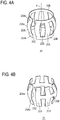
- the cylindrical spring 20 has a plurality of rectangular leaf spring portions 20A that are arranged at intervals in the circumferential direction on the periphery of a hidden virtual column, as shown in Fig. 4A , for example, and that extend in the direction of the central axis X, and two connecting bands 20B that connect the leaf spring portions 20A at both ends in the circumferential direction.
- the central area in the direction of the central axis X of each of the leaf spring portions 20A is curved to project radially outward, forming a curved projection portion 20Aa.
- the connecting bands 20B are separated between one pair of adjacent leaf spring portions 20A among the plurality of rectangular leaf spring portions 20A, forming an opening 20C.
- the shaft supporter 30 includes a base portion 31 having a square block shape and a cylindrical portion 32 rising at a right angle from the front face of the base portion.
- the cylindrical portion 32 has a circular through shaft hole 32A around the central axis X, and a tapered face 32d the diameter of which increases outward is formed at the tip of the through shaft hole 32A.
- the through shaft hole 32A is formed at the tip of the cylindrical portion 32 and has a large-diameter shaft hole portion 32a the inside diameter of which is larger than the inside diameter of the area into which the intermediate portion 12 of the control shaft 10 is inserted so as to fit, or the outside diameter of the intermediate portion 12, and a small-diameter shaft hole portion 32b with a further smaller inside diameter, into which the retention portion 13 of the control shaft 10 is inserted so as to fit, the inside diameter being larger than the outside diameter of the retention portion 13 and smaller than the outside diameter of the intermediate portion 12, and a step 32s is formed on the boundary between the large-diameter shaft hole portion 32a and the small-diameter shaft hole portion 32b.
- connection space 31A is formed for connection to the back face, by enlarging the enlarged shaft hole portion 32c further.
- the length of the intermediate portion 12 in the direction of the central axis X is smaller than the length of the large-diameter shaft hole portion 32a in the direction of the central axis X, and a ring-shaped spring holding space 33 is formed between the inner periphery of the large-diameter shaft hole portion 32a and the outer periphery of the intermediate portion 12 in the state in which the control shaft 10 is inserted deepest into the through shaft hole 32A.
- the electrical signal control section 40 has a rectangular parallelepiped shape that includes a single face matching with the quadrilateral back face of the base portion 31, and includes the housing 41, which includes a variable resistor or a switch that is turned and driven by the drive portion 14, a cover 42 that covers the opening of the housing, terminals 43 where electrical signals are input and output, and set screws 44 that secure the housing 41 to the base portion 31.
- the cover 42 has a hole 42a from which the drive portion 14 is inserted into the housing 41.
- An example of a rotary operation type electronic component having a switch as the electrical signal control section 40 is disclosed, for example, in Japanese Patent Application Laid Open No. 2010-218883 .
- Examples of rotary operation type electronic components having a variable resistor as the electrical signal control section 40 are disclosed, for example, in Japanese Patent Application Laid Open No. 2010-186792 or Japanese Patent Application Laid Open No. 2006-147832 .
- an angle sensor using a magnet and a magnetic sensor that can be turned relatively is disclosed in Japanese Patent Application Laid Open No. H8-236314 .
- the control shaft 10 is locked to the shaft supporter 30 when the ring-shaped groove 13 a of the retention portion 13 is placed next to and outside the small-diameter shaft hole portion 32b and the retaining ring 50 is attached to the ring-shaped groove 13 a, in the state in which the cylindrical spring 20 shown in Fig. 4A is mounted to the outer periphery of the retention portion 13 of the control shaft 10 and the control shaft 10 is inserted into the shaft supporter 30.
- the spring holding space 33 is formed between the outer periphery of the retention portion 13 and the inner periphery of the large-diameter shaft hole portion 32a, and the position of the step 13s of the control shaft 10 in the direction of the central axis X and the position of the step 32s of the through shaft hole 32A in the direction of the central axis X are determined such that the length of the space in the direction of the central axis X becomes greater than the length of the cylindrical spring 20 stretched flatways in the direction of the central axis X.
- the drive portion 14 of the control shaft 10 enters the housing 41 of the electrical signal control section 40 through the connection space 31A in the base portion 31 of the shaft supporter 30.
- the cylindrical spring 20 is formed as described below.
- an array of rectangular slits 20D long in the direction of the shorter side of the metal sheet (hereafter width direction) and parallel to one another a plurality of rectangular leaf spring portions 20A connected by two connecting bands 20B at both ends are formed. All the leaf spring portions 20A are pressed together to be curved so that the central areas of the leaf spring portions 20A in their length direction project to the same side with respect to the face of the original metal sheet.
- the cylindrical spring 20 is obtained by rolling the two connecting bands 20B connecting the leaf spring portions 20A in a direction such that the curved areas project radially outward, until the leaf spring portions 20A located at both ends of the array of leaf spring portions 20A connected by the two connecting bands 20B become next to each other.
- the connecting bands 20B serve as both end portions 20Ab of the leaf spring portions 20A.
- the ends of the leaf spring portions act as fulcrums, and the curved projecting central areas act as points of application.
- the minimum inside diameter of the cylindrical spring 20 (inside diameter of the connecting bands 20B) in a free state is set smaller than the outside diameter of the retention portion 13, when the cylindrical spring 20 is mounted to the retention portion 13, the opening 20C between the adjacent leaf spring portions 20A in both ends of the array is widened resiliently, and the cylindrical spring 20 is held onto the retention portion 13 by the spring force. It is designed that the maximum outside diameter (outside diameter in the central areas of the leaf spring portions 20A) of the cylindrical spring 20 in that state becomes larger than the inside diameter of the large-diameter shaft hole portion 32a of the through shaft hole 32A.
- the leaf spring portions 20A are deformed resiliently so as to be pressed radially inward by the inner periphery of the large-diameter shaft hole portion 32a such that the radial height of the leaf spring portions 20A with respect to the retention portion 13 is lowered toward the central axis X, and so as to have an increased length of the leaf spring portions 20A in the direction of the central axis X.
- the surface of the outer periphery of the leaf spring portions 20A is curved and expanded, decreasing the surface roughness.
- the static frictional force between the leaf spring portions 20A and the inner periphery of the through shaft hole 32A becomes smaller than the static frictional force between the connecting bands 20B and the outer periphery of the retention portion 13.
- the friction between the cylindrical spring 20 and the shaft supporter 30 should be increased.
- the friction can be increased easily by increasing the number of leaf spring portions 20A in the cylindrical spring 20 and by increasing the largest possible amount of resilient displacement of the leaf spring portions 20A (height of the curves of the leaf spring portions 20A). Since the number of leaf spring portions 20A and the possible amount of displacement can be selected independently of each other, the high degree of freedom in design makes it easy to design and manufacture small rotary operation type electronic components.
- Fig. 4B shows a first modification of the cylindrical spring 20 in the embodiment shown in Figs. 2 and 3 .
- This modification differs from the one shown in Fig. 4A in the following points:
- a connecting band 20B is formed by connecting the curved, projecting central areas of leaf spring portions 20A; and the both end portions 20Ab of each of the leaf spring portions 20A are separated from the both end portions 20Ab of adjacent leaf spring portions 20A.
- Fig. 4C shows a second modification of the cylindrical spring 20, which differs from the one shown in Fig. 4A in the following structure:
- the connecting bands 20B are cut off, at one end between one pair of two adjacent leaf spring portions 20A, from every second pair of two adjacent leaf spring portions in the circumferential direction and are cut off, at another end between the next pair of two adjacent leaf spring portions 20A, from every second pair of two adjacent leaf spring portions in the circumferential direction.
- each of the leaf spring portions 20A is connected to an adjacent leaf spring portion by the connecting band 20B alternately at one end or another in the circumferential direction.
- Fig. 4D shows a third modification of the cylindrical spring 20. This modification differs from the one shown in Fig. 4C in the following points:
- the leaf spring portions 20A are placed diagonally with respect to the direction of the central axis X so that adjacent leaf spring portions 20A form V shapes; the adjacent leaf spring portions 20A are connected at one end or another directly, not by the connecting band 20B.
- the cylindrical spring 20 does not rotate relatively with respect to the control shaft 10 but rotates slidably on the shaft supporter 30, but on the contrary, the cylindrical spring 20 may not rotate relatively with respect to the shaft supporter 30 and may rotate slidably on the control shaft 10.
- This configuration can be implemented by forming fine irregularities on the curved faces of the radially outward projections of the leaf spring portions 20A of the cylindrical spring 20 to increase the surface roughness, thereby increasing the frictional force between the cylindrical spring 20 and the inner periphery of the through shaft hole 32A to exceed the frictional force between the cylindrical spring 20 and the control shaft 10.
- Fig. 5A shows a fourth modification of the cylindrical spring 20.
- This modification differs from the cylindrical spring 20 shown in Fig. 4A in that the central areas of the leaf spring portions 20A of the cylindrical spring 20 are curved to project radially inward, contrary to the ones shown in Fig. 4A .
- the rotary operation type electronic component using this modification of the spring is assembled by first placing the cylindrical spring 20 in the large-diameter shaft hole portion 32a of the shaft supporter 30 and then putting the control shaft 10 into the through shaft hole 32A of the shaft supporter 30 so that the retention portion 13 of the control shaft 10 is inserted into the cylindrical spring 20.
- the outer peripheries of the connecting bands 20B of the cylindrical spring 20 resiliently come into contact with the inner periphery of the large-diameter shaft hole portion 32a of the shaft supporter 30, and the curved projection portions 20Aa resiliently come into contact with the outer periphery of the retention portion 13 of the control shaft 10.
- Fig. 5B shows a fifth modification of the cylindrical spring 20. This modification differs from the cylindrical spring 20 shown in Fig. 4B in that the central areas of the leaf spring portions 20A connected by the connecting band 20B are curved and project radially inward, contrary to the ones shown in Fig. 4B .
- Fig. 5C shows a sixth modification of the cylindrical spring 20. This modification differs from the cylindrical spring 20 shown in Fig. 4C in that the central areas of the leaf spring portions 20A are curved and project radially inward, contrary to the ones shown in Fig. 4C .
- Fig. 5D shows a seventh modification of the cylindrical spring 20. This modification differs from the cylindrical spring 20 shown in Fig. 4D in that the central areas of the leaf spring portions 20A are curved and project radially inward, contrary to the ones shown in Fig. 4D .
- the present invention can be applied to variable resistors or switches in portable wireless devices, for example.
Landscapes
- Engineering & Computer Science (AREA)
- Microelectronics & Electronic Packaging (AREA)
- Rotary Switch, Piano Key Switch, And Lever Switch (AREA)
- Adjustable Resistors (AREA)
- Mechanisms For Operating Contacts (AREA)
- Telephone Set Structure (AREA)
Claims (12)
- Elektronisches Bauelement mit Drehbetätigung, umfassend:eine säulenförmige Regelstange (10);einen Stangenhalter (30), der ein kreisförmiges Stangendurchgangsloch (32A) aufweist, in das die Regelstange (10) eingefügt wird;eine elektrische Signalregeleinheit (40), die an einem Ende des Stangenhalters (30) angebracht ist und es ermöglicht, ein elektrisches Signal durch eine Drehbetätigung der Regelstange zu regeln; undeine zylindrische Feder (20), die, um die äußere Peripherie der Regelstange zu umgeben, in einem Federhalteraum (33) gehalten wird, der zwischen der äußeren Peripherie der Regelstange und der inneren Peripherie des Stangendurchgangslochs gebildet ist und eine Ringform mit einer Öffnung (20C) aufweist, die in Richtung der mittleren Achse ausgeschnitten ist;dadurch gekennzeichnet, dass die zylindrische Feder (20) eine Vielzahl von Blattfederteilen (20A) umfasst, die sich in der Richtung der mittleren Achse (X) der Regelstange erstrecken, die in der Umfangsrichtung der Regelstange miteinander verbunden sind, und die an der äußeren Peripherie der Regelstange angeordnet sind;die Vielzahl von Blattfederteilen (20A) gekrümmte Vorsprungsteile aufweist, die durch Krümmen ihrer mittleren Bereiche in der Längsrichtung gebildet werden, um in Richtung auf die gleiche Seite vorzustehen, bei der es sich um die radial innere oder äußere Seite der zylindrischen Feder handelt, wobei sie zwischen der äußeren Peripherie der Regelstange (10) und der inneren Peripherie des Stangendurchgangslochs (32A) federelastisch angeordnet sind und radial entgegengesetzte Druckkräfte an den beiden Endteilen der Blattfederteile und der gekrümmten Vorsprungsteile erfahren.
- Elektronisches Bauelement mit Drehbetätigung nach Anspruch 1,
wobei die Regelstange Folgendes umfasst:einen säulenförmigen Regelteil;einen säulenförmigen Zwischenteil, der sich koaxial von dem Regelteil aus erstreckt und einen kleineren Durchmesser aufweist;einen säulenförmigen Rückhalteteil, der sich koaxial von dem Zwischenteil aus erstreckt und einen noch kleineren Durchmesser aufweist; undeinen säulenförmigen Antriebsteil, der sich koaxial von dem Rückhalteteil aus erstreckt und in die elektrische Signalregeleinheit eindringt;wobei der Stangenhalter Folgendes umfasst:einen zylindrischen Teil, in dem das Stangendurchgangsloch gebildet ist; undeinen Basisteil, der mit dem zylindrischen Teil an einem Ende des zylindrischen Teils in der Richtung der mittleren Achse des zylindrischen Teils einstückig gebildet ist und einen Verbindungsraum umfasst, der zur Verbindung von dem Stangendurchgangsloch bis zu der elektrischen Signalregeleinheit gebildet ist;wobei das Stangendurchgangsloch Folgendes umfasst:einen Stangenlochteil mit großem Durchmesser, der einen Innendurchmesser aufweist, der größer als der Außendurchmesser des Zwischenteils ist; undeinen Stangenlochteil mit kleinem Durchmesser, der sich von dem Stangenlochteil mit großem Durchmesser aus erstreckt und einen Innendurchmesser aufweist, der größer als der Außendurchmesser des Rückhalteteils und kleiner als der Außendurchmesser des Zwischenteils ist; unddie zylindrische Feder in dem Halteraum gehalten wird, wobei der Halteraum zwischen der äußeren Peripherie des Rückhalteteils und der inneren Peripherie des Stangenlochteils mit großem Durchmesser zwischen einer Stufe an der Grenze zwischen dem Zwischenteil und dem Rückhalteteil und einer Stufe an der Grenze zwischen dem Stangenlochteil mit großem Durchmesser und dem Stangenlochteil mit kleinem Durchmesser gebildet ist. - Elektronisches Bauelement mit Drehbetätigung nach Anspruch 1 oder 2, wobei die Vielzahl von Blattfederteilen der zylindrischen Feder an beiden Enden mit einem ersten Verbindungsband und einem zweiten Verbindungsband verbunden ist.
- Elektronisches Bauelement mit Drehbetätigung nach Anspruch 1 oder 2, wobei die Vielzahl von Blattfederteilen der zylindrischen Feder an ihren mittleren Bereichen mit einem Verbindungsband verbunden ist.
- Elektronisches Bauelement mit Drehbetätigung nach Anspruch 1 oder 2, wobei jeder der Blattfederteile mit umfangsmäßig angrenzenden Teilen abwechselnd an einem Ende und einem anderen Ende mit Verbindungsbändern verbunden ist.
- Elektronisches Bauelement mit Drehbetätigung nach Anspruch 1 oder 2, wobei Paare von angrenzenden Blattfederteilen der Vielzahl von Blattfederteilen der zylindrischen Feder angeordnet sind, so dass ihre Enden miteinander verbunden sind, um V-Formen zu bilden.
- Elektronisches Bauelement mit Drehbetätigung nach Anspruch 1 oder 2, wobei die mittleren Bereiche der Vielzahl von Blattfederteilen der zylindrischen Feder gekrümmt sind, um radial nach außen vorzustehen.
- Elektronisches Bauelement mit Drehbetätigung nach Anspruch 3, wobei die mittleren Bereiche der Vielzahl von Blattfederteilen der zylindrischen Feder gekrümmt sind, um radial nach außen vorzustehen.
- Elektronisches Bauelement mit Drehbetätigung nach Anspruch 4, wobei die mittleren Bereiche der Vielzahl von Blattfederteilen der zylindrischen Feder gekrümmt sind, um radial nach außen vorzustehen.
- Elektronisches Bauelement mit Drehbetätigung nach Anspruch 1 oder 2, wobei die mittleren Bereiche der Vielzahl von Blattfederteilen der zylindrischen Feder gekrümmt sind, um radial nach innen vorzustehen.
- Elektronisches Bauelement mit Drehbetätigung nach Anspruch 3, wobei die mittleren Bereiche der Vielzahl von Blattfederteilen der zylindrischen Feder gekrümmt sind, um radial nach innen vorzustehen.
- Elektronisches Bauelement mit Drehbetätigung nach Anspruch 4, wobei die mittleren Bereiche der Vielzahl von Blattfederteilen der zylindrischen Feder gekrümmt sind, um radial nach innen vorzustehen.
Applications Claiming Priority (2)
| Application Number | Priority Date | Filing Date | Title |
|---|---|---|---|
| JP2012267990A JP5914312B2 (ja) | 2012-12-07 | 2012-12-07 | 回転操作型電子部品 |
| PCT/JP2013/079982 WO2014087783A1 (ja) | 2012-12-07 | 2013-11-06 | 回転操作型電子部品 |
Publications (3)
| Publication Number | Publication Date |
|---|---|
| EP2930730A1 EP2930730A1 (de) | 2015-10-14 |
| EP2930730A4 EP2930730A4 (de) | 2016-07-13 |
| EP2930730B1 true EP2930730B1 (de) | 2017-03-15 |
Family
ID=50883210
Family Applications (1)
| Application Number | Title | Priority Date | Filing Date |
|---|---|---|---|
| EP13861175.1A Active EP2930730B1 (de) | 2012-12-07 | 2013-11-06 | Elektronisches bauelement mit drehbetrieb |
Country Status (8)
| Country | Link |
|---|---|
| US (1) | US9412538B2 (de) |
| EP (1) | EP2930730B1 (de) |
| JP (1) | JP5914312B2 (de) |
| KR (1) | KR101698024B1 (de) |
| CN (1) | CN104903987B (de) |
| MY (1) | MY172418A (de) |
| TW (1) | TWI587344B (de) |
| WO (1) | WO2014087783A1 (de) |
Families Citing this family (12)
| Publication number | Priority date | Publication date | Assignee | Title |
|---|---|---|---|---|
| JP6568544B2 (ja) * | 2015-01-13 | 2019-08-28 | 北陸電気工業株式会社 | フォースセンサユニット |
| JP6469551B2 (ja) * | 2015-08-27 | 2019-02-13 | アルプス電気株式会社 | 入力装置 |
| JP6496225B2 (ja) * | 2015-09-29 | 2019-04-03 | アルプスアルパイン株式会社 | 回転型電気部品 |
| US11206897B2 (en) | 2016-02-23 | 2021-12-28 | Nike, Inc. | Ground-engaging structures for articles of footwear |
| CN106024479A (zh) * | 2016-07-01 | 2016-10-12 | 海信(广东)空调有限公司 | 一种旋钮式开关结构 |
| JP6767821B2 (ja) * | 2016-09-14 | 2020-10-14 | アルプスアルパイン株式会社 | 操作装置及び軸受部製造方法 |
| DE202017100925U1 (de) * | 2017-02-20 | 2018-05-24 | Hans Heidolph GmbH | Bedienelement für ein Laborgerät |
| WO2018158905A1 (ja) * | 2017-03-02 | 2018-09-07 | 東京コスモス電機株式会社 | 回転操作部品 |
| CN107131893B (zh) * | 2017-05-04 | 2019-06-18 | 湖南科技大学 | 高压断路器操动机构在线监测用角位移传感器 |
| JP7262240B2 (ja) | 2019-02-15 | 2023-04-21 | 株式会社小松製作所 | 作業機械の操作装置、および作業機械 |
| US11880219B2 (en) * | 2020-01-27 | 2024-01-23 | Tokyo Cosmos Electric Co., Ltd. | Rotationally operated electronic component |
| USD1003260S1 (en) * | 2021-03-12 | 2023-10-31 | Shin-Etsu Polymer Co., Ltd. | Push button for switches |
Family Cites Families (17)
| Publication number | Priority date | Publication date | Assignee | Title |
|---|---|---|---|---|
| JPH0420201A (ja) | 1990-05-15 | 1992-01-23 | Iseki & Co Ltd | 苗植機等のローリング装置 |
| JP2510372Y2 (ja) * | 1990-06-08 | 1996-09-11 | 松下電器産業株式会社 | 電子部品の軸受装置 |
| EP0623942A1 (de) * | 1993-04-20 | 1994-11-09 | FRITZ HARTMANN GERÄTEBAU GMBH & CO KG | Codiervorrichtung |
| JP3017034B2 (ja) * | 1994-12-26 | 2000-03-06 | アルプス電気株式会社 | 回転操作型電気部品 |
| JP3475549B2 (ja) | 1995-02-24 | 2003-12-08 | 株式会社デンソー | 非接触型位置センサ |
| JP3690111B2 (ja) * | 1998-05-12 | 2005-08-31 | 松下電器産業株式会社 | 車載用回転操作型電子部品 |
| JP3855498B2 (ja) * | 1998-10-23 | 2006-12-13 | 松下電器産業株式会社 | 回転操作型電子部品およびその製造方法 |
| JP3952642B2 (ja) * | 1999-09-20 | 2007-08-01 | 松下電器産業株式会社 | 押圧・回転操作型電子部品 |
| JP2003115237A (ja) * | 2001-10-04 | 2003-04-18 | Matsushita Electric Ind Co Ltd | 回転型電子部品 |
| US6570105B1 (en) * | 2002-05-06 | 2003-05-27 | Lear Corporation | Retractable rotary switch cell |
| JP2006147832A (ja) | 2004-11-19 | 2006-06-08 | Alps Electric Co Ltd | 可変抵抗器 |
| CN201107801Y (zh) * | 2007-07-30 | 2008-08-27 | 升威电子制品(东莞)有限公司 | 一种自动复位开关 |
| US8084703B2 (en) * | 2007-12-18 | 2011-12-27 | Panasonic Corporation | Rotating operation type electronic component, and electronic device including the same |
| JP4458181B2 (ja) * | 2008-04-24 | 2010-04-28 | ソニー株式会社 | 電気接触子および電子機器 |
| JP5256070B2 (ja) | 2009-02-10 | 2013-08-07 | 東京コスモス電機株式会社 | 電子部品のクリック機構、可変抵抗器 |
| JP4759071B2 (ja) | 2009-03-17 | 2011-08-31 | 東京コスモス電機株式会社 | 回転型スイッチ |
| US8766121B2 (en) * | 2011-05-26 | 2014-07-01 | Motorola Solutions, Inc. | Rotary control switch |
-
2012
- 2012-12-07 JP JP2012267990A patent/JP5914312B2/ja active Active
-
2013
- 2013-11-06 CN CN201380063144.5A patent/CN104903987B/zh active Active
- 2013-11-06 EP EP13861175.1A patent/EP2930730B1/de active Active
- 2013-11-06 WO PCT/JP2013/079982 patent/WO2014087783A1/ja not_active Ceased
- 2013-11-06 US US14/438,391 patent/US9412538B2/en active Active
- 2013-11-06 KR KR1020157012397A patent/KR101698024B1/ko active Active
- 2013-11-06 MY MYPI2015701384A patent/MY172418A/en unknown
- 2013-11-07 TW TW102140487A patent/TWI587344B/zh active
Non-Patent Citations (1)
| Title |
|---|
| None * |
Also Published As
| Publication number | Publication date |
|---|---|
| CN104903987A (zh) | 2015-09-09 |
| EP2930730A1 (de) | 2015-10-14 |
| KR20150068474A (ko) | 2015-06-19 |
| EP2930730A4 (de) | 2016-07-13 |
| US9412538B2 (en) | 2016-08-09 |
| TW201432767A (zh) | 2014-08-16 |
| HK1210867A1 (en) | 2016-05-06 |
| KR101698024B1 (ko) | 2017-01-19 |
| TWI587344B (zh) | 2017-06-11 |
| MY172418A (en) | 2019-11-25 |
| JP2014116125A (ja) | 2014-06-26 |
| JP5914312B2 (ja) | 2016-05-11 |
| CN104903987B (zh) | 2017-05-10 |
| WO2014087783A1 (ja) | 2014-06-12 |
| US20150287557A1 (en) | 2015-10-08 |
Similar Documents
| Publication | Publication Date | Title |
|---|---|---|
| US9412538B2 (en) | Rotary operation type electronic component | |
| JP4759071B2 (ja) | 回転型スイッチ | |
| KR101662825B1 (ko) | 전기 부품의 클릭 기구 | |
| US10211012B2 (en) | Click mechanism for electric part | |
| JP5852669B2 (ja) | 回転操作型電子部品の軸受構造 | |
| JP2005259634A (ja) | 回転型電気部品 | |
| CN103843095B (zh) | 旋转操作式电子部件的轴承结构 | |
| HK1210867B (en) | Rotary-operation-type electronic component | |
| JP5862477B2 (ja) | トルク可変装置、及び電子機器 | |
| JP2019114621A (ja) | 2連形接触式ポテンショメータ | |
| JP2019047540A (ja) | ステータコア | |
| KR102740866B1 (ko) | 가변저항을 이용한 멀티스위치 | |
| CN212162292U (zh) | 旋转连接器 | |
| JP2013102559A (ja) | Dcモータの滑り軸受用支持ばね及びそれを用いたdcモータ | |
| JP2009265016A (ja) | ロータリエンコーダ | |
| JP2005222979A (ja) | 操作つまみ付き回転型電子部品 | |
| JP2008159907A (ja) | 回転式電子部品 | |
| HK1194200B (en) | Bearing structure for rotary control-type electronic component |
Legal Events
| Date | Code | Title | Description |
|---|---|---|---|
| PUAI | Public reference made under article 153(3) epc to a published international application that has entered the european phase |
Free format text: ORIGINAL CODE: 0009012 |
|
| 17P | Request for examination filed |
Effective date: 20150707 |
|
| AK | Designated contracting states |
Kind code of ref document: A1 Designated state(s): AL AT BE BG CH CY CZ DE DK EE ES FI FR GB GR HR HU IE IS IT LI LT LU LV MC MK MT NL NO PL PT RO RS SE SI SK SM TR |
|
| AX | Request for extension of the european patent |
Extension state: BA ME |
|
| DAX | Request for extension of the european patent (deleted) | ||
| RA4 | Supplementary search report drawn up and despatched (corrected) |
Effective date: 20160610 |
|
| RIC1 | Information provided on ipc code assigned before grant |
Ipc: H01C 10/46 20060101ALI20160606BHEP Ipc: H01H 3/10 20060101ALN20160606BHEP Ipc: H01C 10/14 20060101ALI20160606BHEP Ipc: H01H 19/20 20060101AFI20160606BHEP Ipc: H01H 19/58 20060101ALN20160606BHEP |
|
| GRAP | Despatch of communication of intention to grant a patent |
Free format text: ORIGINAL CODE: EPIDOSNIGR1 |
|
| RIC1 | Information provided on ipc code assigned before grant |
Ipc: H01C 10/14 20060101ALI20160920BHEP Ipc: H01H 19/58 20060101ALN20160920BHEP Ipc: H01H 19/20 20060101AFI20160920BHEP Ipc: H01H 3/10 20060101ALN20160920BHEP Ipc: H01C 10/46 20060101ALI20160920BHEP |
|
| INTG | Intention to grant announced |
Effective date: 20161017 |
|
| GRAS | Grant fee paid |
Free format text: ORIGINAL CODE: EPIDOSNIGR3 |
|
| STAA | Information on the status of an ep patent application or granted ep patent |
Free format text: STATUS: GRANT OF PATENT IS INTENDED |
|
| GRAA | (expected) grant |
Free format text: ORIGINAL CODE: 0009210 |
|
| STAA | Information on the status of an ep patent application or granted ep patent |
Free format text: STATUS: THE PATENT HAS BEEN GRANTED |
|
| RIN1 | Information on inventor provided before grant (corrected) |
Inventor name: FUKUNAGA, TARO |
|
| AK | Designated contracting states |
Kind code of ref document: B1 Designated state(s): AL AT BE BG CH CY CZ DE DK EE ES FI FR GB GR HR HU IE IS IT LI LT LU LV MC MK MT NL NO PL PT RO RS SE SI SK SM TR |
|
| REG | Reference to a national code |
Ref country code: CH Ref legal event code: EP Ref country code: GB Ref legal event code: FG4D |
|
| RIN2 | Information on inventor provided after grant (corrected) |
Inventor name: FUKUNAGA, TARO |
|
| REG | Reference to a national code |
Ref country code: CH Ref legal event code: NV Representative=s name: E. BLUM AND CO. AG PATENT- UND MARKENANWAELTE , CH |
|
| REG | Reference to a national code |
Ref country code: IE Ref legal event code: FG4D |
|
| REG | Reference to a national code |
Ref country code: AT Ref legal event code: REF Ref document number: 876334 Country of ref document: AT Kind code of ref document: T Effective date: 20170415 |
|
| REG | Reference to a national code |
Ref country code: DE Ref legal event code: R096 Ref document number: 602013018742 Country of ref document: DE |
|
| REG | Reference to a national code |
Ref country code: NL Ref legal event code: MP Effective date: 20170315 |
|
| REG | Reference to a national code |
Ref country code: LT Ref legal event code: MG4D |
|
| PG25 | Lapsed in a contracting state [announced via postgrant information from national office to epo] |
Ref country code: LT Free format text: LAPSE BECAUSE OF FAILURE TO SUBMIT A TRANSLATION OF THE DESCRIPTION OR TO PAY THE FEE WITHIN THE PRESCRIBED TIME-LIMIT Effective date: 20170315 Ref country code: GR Free format text: LAPSE BECAUSE OF FAILURE TO SUBMIT A TRANSLATION OF THE DESCRIPTION OR TO PAY THE FEE WITHIN THE PRESCRIBED TIME-LIMIT Effective date: 20170616 Ref country code: HR Free format text: LAPSE BECAUSE OF FAILURE TO SUBMIT A TRANSLATION OF THE DESCRIPTION OR TO PAY THE FEE WITHIN THE PRESCRIBED TIME-LIMIT Effective date: 20170315 Ref country code: NO Free format text: LAPSE BECAUSE OF FAILURE TO SUBMIT A TRANSLATION OF THE DESCRIPTION OR TO PAY THE FEE WITHIN THE PRESCRIBED TIME-LIMIT Effective date: 20170615 Ref country code: FI Free format text: LAPSE BECAUSE OF FAILURE TO SUBMIT A TRANSLATION OF THE DESCRIPTION OR TO PAY THE FEE WITHIN THE PRESCRIBED TIME-LIMIT Effective date: 20170315 |
|
| REG | Reference to a national code |
Ref country code: AT Ref legal event code: MK05 Ref document number: 876334 Country of ref document: AT Kind code of ref document: T Effective date: 20170315 |
|
| PG25 | Lapsed in a contracting state [announced via postgrant information from national office to epo] |
Ref country code: LV Free format text: LAPSE BECAUSE OF FAILURE TO SUBMIT A TRANSLATION OF THE DESCRIPTION OR TO PAY THE FEE WITHIN THE PRESCRIBED TIME-LIMIT Effective date: 20170315 Ref country code: RS Free format text: LAPSE BECAUSE OF FAILURE TO SUBMIT A TRANSLATION OF THE DESCRIPTION OR TO PAY THE FEE WITHIN THE PRESCRIBED TIME-LIMIT Effective date: 20170315 Ref country code: SE Free format text: LAPSE BECAUSE OF FAILURE TO SUBMIT A TRANSLATION OF THE DESCRIPTION OR TO PAY THE FEE WITHIN THE PRESCRIBED TIME-LIMIT Effective date: 20170315 Ref country code: BG Free format text: LAPSE BECAUSE OF FAILURE TO SUBMIT A TRANSLATION OF THE DESCRIPTION OR TO PAY THE FEE WITHIN THE PRESCRIBED TIME-LIMIT Effective date: 20170615 |
|
| PG25 | Lapsed in a contracting state [announced via postgrant information from national office to epo] |
Ref country code: NL Free format text: LAPSE BECAUSE OF FAILURE TO SUBMIT A TRANSLATION OF THE DESCRIPTION OR TO PAY THE FEE WITHIN THE PRESCRIBED TIME-LIMIT Effective date: 20170315 |
|
| PG25 | Lapsed in a contracting state [announced via postgrant information from national office to epo] |
Ref country code: SK Free format text: LAPSE BECAUSE OF FAILURE TO SUBMIT A TRANSLATION OF THE DESCRIPTION OR TO PAY THE FEE WITHIN THE PRESCRIBED TIME-LIMIT Effective date: 20170315 Ref country code: CZ Free format text: LAPSE BECAUSE OF FAILURE TO SUBMIT A TRANSLATION OF THE DESCRIPTION OR TO PAY THE FEE WITHIN THE PRESCRIBED TIME-LIMIT Effective date: 20170315 Ref country code: EE Free format text: LAPSE BECAUSE OF FAILURE TO SUBMIT A TRANSLATION OF THE DESCRIPTION OR TO PAY THE FEE WITHIN THE PRESCRIBED TIME-LIMIT Effective date: 20170315 Ref country code: IT Free format text: LAPSE BECAUSE OF FAILURE TO SUBMIT A TRANSLATION OF THE DESCRIPTION OR TO PAY THE FEE WITHIN THE PRESCRIBED TIME-LIMIT Effective date: 20170315 Ref country code: AT Free format text: LAPSE BECAUSE OF FAILURE TO SUBMIT A TRANSLATION OF THE DESCRIPTION OR TO PAY THE FEE WITHIN THE PRESCRIBED TIME-LIMIT Effective date: 20170315 Ref country code: ES Free format text: LAPSE BECAUSE OF FAILURE TO SUBMIT A TRANSLATION OF THE DESCRIPTION OR TO PAY THE FEE WITHIN THE PRESCRIBED TIME-LIMIT Effective date: 20170315 Ref country code: RO Free format text: LAPSE BECAUSE OF FAILURE TO SUBMIT A TRANSLATION OF THE DESCRIPTION OR TO PAY THE FEE WITHIN THE PRESCRIBED TIME-LIMIT Effective date: 20170315 |
|
| PG25 | Lapsed in a contracting state [announced via postgrant information from national office to epo] |
Ref country code: PT Free format text: LAPSE BECAUSE OF FAILURE TO SUBMIT A TRANSLATION OF THE DESCRIPTION OR TO PAY THE FEE WITHIN THE PRESCRIBED TIME-LIMIT Effective date: 20170717 Ref country code: PL Free format text: LAPSE BECAUSE OF FAILURE TO SUBMIT A TRANSLATION OF THE DESCRIPTION OR TO PAY THE FEE WITHIN THE PRESCRIBED TIME-LIMIT Effective date: 20170315 Ref country code: IS Free format text: LAPSE BECAUSE OF FAILURE TO SUBMIT A TRANSLATION OF THE DESCRIPTION OR TO PAY THE FEE WITHIN THE PRESCRIBED TIME-LIMIT Effective date: 20170715 Ref country code: SM Free format text: LAPSE BECAUSE OF FAILURE TO SUBMIT A TRANSLATION OF THE DESCRIPTION OR TO PAY THE FEE WITHIN THE PRESCRIBED TIME-LIMIT Effective date: 20170315 |
|
| REG | Reference to a national code |
Ref country code: DE Ref legal event code: R097 Ref document number: 602013018742 Country of ref document: DE |
|
| PLBE | No opposition filed within time limit |
Free format text: ORIGINAL CODE: 0009261 |
|
| STAA | Information on the status of an ep patent application or granted ep patent |
Free format text: STATUS: NO OPPOSITION FILED WITHIN TIME LIMIT |
|
| PG25 | Lapsed in a contracting state [announced via postgrant information from national office to epo] |
Ref country code: DK Free format text: LAPSE BECAUSE OF FAILURE TO SUBMIT A TRANSLATION OF THE DESCRIPTION OR TO PAY THE FEE WITHIN THE PRESCRIBED TIME-LIMIT Effective date: 20170315 |
|
| 26N | No opposition filed |
Effective date: 20171218 |
|
| PG25 | Lapsed in a contracting state [announced via postgrant information from national office to epo] |
Ref country code: SI Free format text: LAPSE BECAUSE OF FAILURE TO SUBMIT A TRANSLATION OF THE DESCRIPTION OR TO PAY THE FEE WITHIN THE PRESCRIBED TIME-LIMIT Effective date: 20170315 |
|
| REG | Reference to a national code |
Ref country code: DE Ref legal event code: R119 Ref document number: 602013018742 Country of ref document: DE |
|
| PG25 | Lapsed in a contracting state [announced via postgrant information from national office to epo] |
Ref country code: MC Free format text: LAPSE BECAUSE OF FAILURE TO SUBMIT A TRANSLATION OF THE DESCRIPTION OR TO PAY THE FEE WITHIN THE PRESCRIBED TIME-LIMIT Effective date: 20170315 |
|
| GBPC | Gb: european patent ceased through non-payment of renewal fee |
Effective date: 20171106 |
|
| PG25 | Lapsed in a contracting state [announced via postgrant information from national office to epo] |
Ref country code: LU Free format text: LAPSE BECAUSE OF NON-PAYMENT OF DUE FEES Effective date: 20171106 |
|
| REG | Reference to a national code |
Ref country code: FR Ref legal event code: ST Effective date: 20180731 Ref country code: BE Ref legal event code: MM Effective date: 20171130 |
|
| REG | Reference to a national code |
Ref country code: IE Ref legal event code: MM4A |
|
| PG25 | Lapsed in a contracting state [announced via postgrant information from national office to epo] |
Ref country code: MT Free format text: LAPSE BECAUSE OF NON-PAYMENT OF DUE FEES Effective date: 20171106 |
|
| PG25 | Lapsed in a contracting state [announced via postgrant information from national office to epo] |
Ref country code: DE Free format text: LAPSE BECAUSE OF NON-PAYMENT OF DUE FEES Effective date: 20180602 Ref country code: IE Free format text: LAPSE BECAUSE OF NON-PAYMENT OF DUE FEES Effective date: 20171106 Ref country code: FR Free format text: LAPSE BECAUSE OF NON-PAYMENT OF DUE FEES Effective date: 20171130 |
|
| PG25 | Lapsed in a contracting state [announced via postgrant information from national office to epo] |
Ref country code: BE Free format text: LAPSE BECAUSE OF NON-PAYMENT OF DUE FEES Effective date: 20171130 Ref country code: GB Free format text: LAPSE BECAUSE OF NON-PAYMENT OF DUE FEES Effective date: 20171106 |
|
| PG25 | Lapsed in a contracting state [announced via postgrant information from national office to epo] |
Ref country code: HU Free format text: LAPSE BECAUSE OF FAILURE TO SUBMIT A TRANSLATION OF THE DESCRIPTION OR TO PAY THE FEE WITHIN THE PRESCRIBED TIME-LIMIT; INVALID AB INITIO Effective date: 20131106 |
|
| PG25 | Lapsed in a contracting state [announced via postgrant information from national office to epo] |
Ref country code: CY Free format text: LAPSE BECAUSE OF FAILURE TO SUBMIT A TRANSLATION OF THE DESCRIPTION OR TO PAY THE FEE WITHIN THE PRESCRIBED TIME-LIMIT Effective date: 20170315 |
|
| PG25 | Lapsed in a contracting state [announced via postgrant information from national office to epo] |
Ref country code: MK Free format text: LAPSE BECAUSE OF FAILURE TO SUBMIT A TRANSLATION OF THE DESCRIPTION OR TO PAY THE FEE WITHIN THE PRESCRIBED TIME-LIMIT Effective date: 20170315 |
|
| PG25 | Lapsed in a contracting state [announced via postgrant information from national office to epo] |
Ref country code: TR Free format text: LAPSE BECAUSE OF FAILURE TO SUBMIT A TRANSLATION OF THE DESCRIPTION OR TO PAY THE FEE WITHIN THE PRESCRIBED TIME-LIMIT Effective date: 20170315 |
|
| PG25 | Lapsed in a contracting state [announced via postgrant information from national office to epo] |
Ref country code: AL Free format text: LAPSE BECAUSE OF FAILURE TO SUBMIT A TRANSLATION OF THE DESCRIPTION OR TO PAY THE FEE WITHIN THE PRESCRIBED TIME-LIMIT Effective date: 20170315 |
|
| REG | Reference to a national code |
Ref country code: CH Ref legal event code: U11 Free format text: ST27 STATUS EVENT CODE: U-0-0-U10-U11 (AS PROVIDED BY THE NATIONAL OFFICE) Effective date: 20251201 |
|
| PGFP | Annual fee paid to national office [announced via postgrant information from national office to epo] |
Ref country code: CH Payment date: 20251201 Year of fee payment: 13 |