EP2919840B1 - Zonenheizung für atemkreisläufe - Google Patents
Zonenheizung für atemkreisläufe Download PDFInfo
- Publication number
- EP2919840B1 EP2919840B1 EP13854947.2A EP13854947A EP2919840B1 EP 2919840 B1 EP2919840 B1 EP 2919840B1 EP 13854947 A EP13854947 A EP 13854947A EP 2919840 B1 EP2919840 B1 EP 2919840B1
- Authority
- EP
- European Patent Office
- Prior art keywords
- sensor
- segment
- circuit
- power
- patient
- Prior art date
- Legal status (The legal status is an assumption and is not a legal conclusion. Google has not performed a legal analysis and makes no representation as to the accuracy of the status listed.)
- Active
Links
- 230000000241 respiratory effect Effects 0.000 title claims description 42
- 238000010438 heat treatment Methods 0.000 title description 85
- 239000007789 gas Substances 0.000 claims description 108
- QVGXLLKOCUKJST-UHFFFAOYSA-N atomic oxygen Chemical compound [O] QVGXLLKOCUKJST-UHFFFAOYSA-N 0.000 claims description 12
- 239000001301 oxygen Substances 0.000 claims description 12
- 229910052760 oxygen Inorganic materials 0.000 claims description 12
- 230000002787 reinforcement Effects 0.000 claims description 9
- 230000007613 environmental effect Effects 0.000 claims 2
- 230000003434 inspiratory effect Effects 0.000 description 262
- 239000002131 composite material Substances 0.000 description 59
- 230000029058 respiratory gaseous exchange Effects 0.000 description 39
- 238000000034 method Methods 0.000 description 19
- 238000010586 diagram Methods 0.000 description 18
- 239000011324 bead Substances 0.000 description 16
- 230000008878 coupling Effects 0.000 description 11
- 238000010168 coupling process Methods 0.000 description 11
- 238000005859 coupling reaction Methods 0.000 description 11
- 239000003570 air Substances 0.000 description 10
- 238000004891 communication Methods 0.000 description 10
- 230000009977 dual effect Effects 0.000 description 10
- 239000007788 liquid Substances 0.000 description 10
- 238000005259 measurement Methods 0.000 description 10
- 230000008901 benefit Effects 0.000 description 9
- 239000000463 material Substances 0.000 description 9
- 238000012360 testing method Methods 0.000 description 9
- XLYOFNOQVPJJNP-UHFFFAOYSA-N water Substances O XLYOFNOQVPJJNP-UHFFFAOYSA-N 0.000 description 9
- 230000008859 change Effects 0.000 description 8
- 239000000203 mixture Substances 0.000 description 8
- 238000009833 condensation Methods 0.000 description 7
- 230000005494 condensation Effects 0.000 description 7
- 239000003990 capacitor Substances 0.000 description 6
- 238000012546 transfer Methods 0.000 description 6
- 238000013500 data storage Methods 0.000 description 5
- 230000000694 effects Effects 0.000 description 5
- 239000004033 plastic Substances 0.000 description 5
- 229920003023 plastic Polymers 0.000 description 5
- 230000008569 process Effects 0.000 description 5
- 239000004020 conductor Substances 0.000 description 4
- 238000013461 design Methods 0.000 description 4
- 230000006870 function Effects 0.000 description 4
- 230000004048 modification Effects 0.000 description 4
- 238000012986 modification Methods 0.000 description 4
- 230000000295 complement effect Effects 0.000 description 3
- 239000010949 copper Substances 0.000 description 3
- 230000007423 decrease Effects 0.000 description 3
- 238000001125 extrusion Methods 0.000 description 3
- 229910052751 metal Inorganic materials 0.000 description 3
- 239000002184 metal Substances 0.000 description 3
- 238000012544 monitoring process Methods 0.000 description 3
- 230000004044 response Effects 0.000 description 3
- 239000007787 solid Substances 0.000 description 3
- 238000003860 storage Methods 0.000 description 3
- XKRFYHLGVUSROY-UHFFFAOYSA-N Argon Chemical compound [Ar] XKRFYHLGVUSROY-UHFFFAOYSA-N 0.000 description 2
- 0 CCC1C=CC[C@@]1C*=C Chemical compound CCC1C=CC[C@@]1C*=C 0.000 description 2
- RYGMFSIKBFXOCR-UHFFFAOYSA-N Copper Chemical compound [Cu] RYGMFSIKBFXOCR-UHFFFAOYSA-N 0.000 description 2
- 229920002614 Polyether block amide Polymers 0.000 description 2
- 239000004743 Polypropylene Substances 0.000 description 2
- 239000004433 Thermoplastic polyurethane Substances 0.000 description 2
- 229910052782 aluminium Inorganic materials 0.000 description 2
- XAGFODPZIPBFFR-UHFFFAOYSA-N aluminium Chemical compound [Al] XAGFODPZIPBFFR-UHFFFAOYSA-N 0.000 description 2
- 239000012080 ambient air Substances 0.000 description 2
- 238000005452 bending Methods 0.000 description 2
- 230000009286 beneficial effect Effects 0.000 description 2
- 230000015572 biosynthetic process Effects 0.000 description 2
- 238000009529 body temperature measurement Methods 0.000 description 2
- 238000004364 calculation method Methods 0.000 description 2
- 238000004590 computer program Methods 0.000 description 2
- 229920001940 conductive polymer Polymers 0.000 description 2
- 229910052802 copper Inorganic materials 0.000 description 2
- 230000001419 dependent effect Effects 0.000 description 2
- 238000009795 derivation Methods 0.000 description 2
- 229920001971 elastomer Polymers 0.000 description 2
- 239000000806 elastomer Substances 0.000 description 2
- 239000012530 fluid Substances 0.000 description 2
- 239000011810 insulating material Substances 0.000 description 2
- 238000009413 insulation Methods 0.000 description 2
- 229920006124 polyolefin elastomer Polymers 0.000 description 2
- 229920001155 polypropylene Polymers 0.000 description 2
- 230000009467 reduction Effects 0.000 description 2
- 210000002345 respiratory system Anatomy 0.000 description 2
- 239000004065 semiconductor Substances 0.000 description 2
- 229920006344 thermoplastic copolyester Polymers 0.000 description 2
- 229920002803 thermoplastic polyurethane Polymers 0.000 description 2
- 241001631457 Cannula Species 0.000 description 1
- 239000000853 adhesive Substances 0.000 description 1
- 230000001070 adhesive effect Effects 0.000 description 1
- 239000000956 alloy Substances 0.000 description 1
- 229910045601 alloy Inorganic materials 0.000 description 1
- 239000003994 anesthetic gas Substances 0.000 description 1
- 238000013459 approach Methods 0.000 description 1
- 229910052786 argon Inorganic materials 0.000 description 1
- 238000003491 array Methods 0.000 description 1
- 230000000712 assembly Effects 0.000 description 1
- 238000000429 assembly Methods 0.000 description 1
- 230000033228 biological regulation Effects 0.000 description 1
- 238000004422 calculation algorithm Methods 0.000 description 1
- 230000001143 conditioned effect Effects 0.000 description 1
- 239000000356 contaminant Substances 0.000 description 1
- 238000005520 cutting process Methods 0.000 description 1
- 230000032798 delamination Effects 0.000 description 1
- 230000003111 delayed effect Effects 0.000 description 1
- 238000001514 detection method Methods 0.000 description 1
- 230000009699 differential effect Effects 0.000 description 1
- 238000009826 distribution Methods 0.000 description 1
- 238000005265 energy consumption Methods 0.000 description 1
- 238000007373 indentation Methods 0.000 description 1
- 230000002401 inhibitory effect Effects 0.000 description 1
- 230000000977 initiatory effect Effects 0.000 description 1
- 239000000976 ink Substances 0.000 description 1
- 230000003993 interaction Effects 0.000 description 1
- 238000002955 isolation Methods 0.000 description 1
- 238000005304 joining Methods 0.000 description 1
- 229910052743 krypton Inorganic materials 0.000 description 1
- DNNSSWSSYDEUBZ-UHFFFAOYSA-N krypton atom Chemical compound [Kr] DNNSSWSSYDEUBZ-UHFFFAOYSA-N 0.000 description 1
- 238000002357 laparoscopic surgery Methods 0.000 description 1
- 238000004519 manufacturing process Methods 0.000 description 1
- 238000000465 moulding Methods 0.000 description 1
- 239000002105 nanoparticle Substances 0.000 description 1
- 231100000252 nontoxic Toxicity 0.000 description 1
- 230000003000 nontoxic effect Effects 0.000 description 1
- 230000003287 optical effect Effects 0.000 description 1
- 229920000307 polymer substrate Polymers 0.000 description 1
- 230000002265 prevention Effects 0.000 description 1
- 230000005855 radiation Effects 0.000 description 1
- 238000002644 respiratory therapy Methods 0.000 description 1
- 230000000630 rising effect Effects 0.000 description 1
- 238000000926 separation method Methods 0.000 description 1
- 239000000126 substance Substances 0.000 description 1
- 230000002277 temperature effect Effects 0.000 description 1
- 230000007704 transition Effects 0.000 description 1
- 229910052724 xenon Inorganic materials 0.000 description 1
- FHNFHKCVQCLJFQ-UHFFFAOYSA-N xenon atom Chemical compound [Xe] FHNFHKCVQCLJFQ-UHFFFAOYSA-N 0.000 description 1
Images


Classifications
-
- A—HUMAN NECESSITIES
- A61—MEDICAL OR VETERINARY SCIENCE; HYGIENE
- A61M—DEVICES FOR INTRODUCING MEDIA INTO, OR ONTO, THE BODY; DEVICES FOR TRANSDUCING BODY MEDIA OR FOR TAKING MEDIA FROM THE BODY; DEVICES FOR PRODUCING OR ENDING SLEEP OR STUPOR
- A61M16/00—Devices for influencing the respiratory system of patients by gas treatment, e.g. mouth-to-mouth respiration; Tracheal tubes
- A61M16/10—Preparation of respiratory gases or vapours
- A61M16/1075—Preparation of respiratory gases or vapours by influencing the temperature
-
- A—HUMAN NECESSITIES
- A61—MEDICAL OR VETERINARY SCIENCE; HYGIENE
- A61M—DEVICES FOR INTRODUCING MEDIA INTO, OR ONTO, THE BODY; DEVICES FOR TRANSDUCING BODY MEDIA OR FOR TAKING MEDIA FROM THE BODY; DEVICES FOR PRODUCING OR ENDING SLEEP OR STUPOR
- A61M16/00—Devices for influencing the respiratory system of patients by gas treatment, e.g. mouth-to-mouth respiration; Tracheal tubes
- A61M16/08—Bellows; Connecting tubes ; Water traps; Patient circuits
- A61M16/0816—Joints or connectors
-
- A—HUMAN NECESSITIES
- A61—MEDICAL OR VETERINARY SCIENCE; HYGIENE
- A61G—TRANSPORT, PERSONAL CONVEYANCES, OR ACCOMMODATION SPECIALLY ADAPTED FOR PATIENTS OR DISABLED PERSONS; OPERATING TABLES OR CHAIRS; CHAIRS FOR DENTISTRY; FUNERAL DEVICES
- A61G11/00—Baby-incubators; Couveuses
-
- A—HUMAN NECESSITIES
- A61—MEDICAL OR VETERINARY SCIENCE; HYGIENE
- A61M—DEVICES FOR INTRODUCING MEDIA INTO, OR ONTO, THE BODY; DEVICES FOR TRANSDUCING BODY MEDIA OR FOR TAKING MEDIA FROM THE BODY; DEVICES FOR PRODUCING OR ENDING SLEEP OR STUPOR
- A61M16/00—Devices for influencing the respiratory system of patients by gas treatment, e.g. mouth-to-mouth respiration; Tracheal tubes
- A61M16/021—Devices for influencing the respiratory system of patients by gas treatment, e.g. mouth-to-mouth respiration; Tracheal tubes operated by electrical means
- A61M16/022—Control means therefor
- A61M16/024—Control means therefor including calculation means, e.g. using a processor
-
- A—HUMAN NECESSITIES
- A61—MEDICAL OR VETERINARY SCIENCE; HYGIENE
- A61M—DEVICES FOR INTRODUCING MEDIA INTO, OR ONTO, THE BODY; DEVICES FOR TRANSDUCING BODY MEDIA OR FOR TAKING MEDIA FROM THE BODY; DEVICES FOR PRODUCING OR ENDING SLEEP OR STUPOR
- A61M16/00—Devices for influencing the respiratory system of patients by gas treatment, e.g. mouth-to-mouth respiration; Tracheal tubes
- A61M16/08—Bellows; Connecting tubes ; Water traps; Patient circuits
- A61M16/0866—Passive resistors therefor
-
- A—HUMAN NECESSITIES
- A61—MEDICAL OR VETERINARY SCIENCE; HYGIENE
- A61M—DEVICES FOR INTRODUCING MEDIA INTO, OR ONTO, THE BODY; DEVICES FOR TRANSDUCING BODY MEDIA OR FOR TAKING MEDIA FROM THE BODY; DEVICES FOR PRODUCING OR ENDING SLEEP OR STUPOR
- A61M16/00—Devices for influencing the respiratory system of patients by gas treatment, e.g. mouth-to-mouth respiration; Tracheal tubes
- A61M16/08—Bellows; Connecting tubes ; Water traps; Patient circuits
- A61M16/0875—Connecting tubes
-
- A—HUMAN NECESSITIES
- A61—MEDICAL OR VETERINARY SCIENCE; HYGIENE
- A61M—DEVICES FOR INTRODUCING MEDIA INTO, OR ONTO, THE BODY; DEVICES FOR TRANSDUCING BODY MEDIA OR FOR TAKING MEDIA FROM THE BODY; DEVICES FOR PRODUCING OR ENDING SLEEP OR STUPOR
- A61M16/00—Devices for influencing the respiratory system of patients by gas treatment, e.g. mouth-to-mouth respiration; Tracheal tubes
- A61M16/10—Preparation of respiratory gases or vapours
- A61M16/1075—Preparation of respiratory gases or vapours by influencing the temperature
- A61M16/1095—Preparation of respiratory gases or vapours by influencing the temperature in the connecting tubes
-
- A—HUMAN NECESSITIES
- A61—MEDICAL OR VETERINARY SCIENCE; HYGIENE
- A61M—DEVICES FOR INTRODUCING MEDIA INTO, OR ONTO, THE BODY; DEVICES FOR TRANSDUCING BODY MEDIA OR FOR TAKING MEDIA FROM THE BODY; DEVICES FOR PRODUCING OR ENDING SLEEP OR STUPOR
- A61M16/00—Devices for influencing the respiratory system of patients by gas treatment, e.g. mouth-to-mouth respiration; Tracheal tubes
- A61M16/10—Preparation of respiratory gases or vapours
- A61M16/14—Preparation of respiratory gases or vapours by mixing different fluids, one of them being in a liquid phase
- A61M16/16—Devices to humidify the respiration air
- A61M16/161—Devices to humidify the respiration air with means for measuring the humidity
-
- A—HUMAN NECESSITIES
- A61—MEDICAL OR VETERINARY SCIENCE; HYGIENE
- A61M—DEVICES FOR INTRODUCING MEDIA INTO, OR ONTO, THE BODY; DEVICES FOR TRANSDUCING BODY MEDIA OR FOR TAKING MEDIA FROM THE BODY; DEVICES FOR PRODUCING OR ENDING SLEEP OR STUPOR
- A61M39/00—Tubes, tube connectors, tube couplings, valves, access sites or the like, specially adapted for medical use
- A61M39/08—Tubes; Storage means specially adapted therefor
-
- A—HUMAN NECESSITIES
- A61—MEDICAL OR VETERINARY SCIENCE; HYGIENE
- A61G—TRANSPORT, PERSONAL CONVEYANCES, OR ACCOMMODATION SPECIALLY ADAPTED FOR PATIENTS OR DISABLED PERSONS; OPERATING TABLES OR CHAIRS; CHAIRS FOR DENTISTRY; FUNERAL DEVICES
- A61G2210/00—Devices for specific treatment or diagnosis
- A61G2210/70—Devices for specific treatment or diagnosis for cooling
-
- A—HUMAN NECESSITIES
- A61—MEDICAL OR VETERINARY SCIENCE; HYGIENE
- A61G—TRANSPORT, PERSONAL CONVEYANCES, OR ACCOMMODATION SPECIALLY ADAPTED FOR PATIENTS OR DISABLED PERSONS; OPERATING TABLES OR CHAIRS; CHAIRS FOR DENTISTRY; FUNERAL DEVICES
- A61G2210/00—Devices for specific treatment or diagnosis
- A61G2210/90—Devices for specific treatment or diagnosis for heating
-
- A—HUMAN NECESSITIES
- A61—MEDICAL OR VETERINARY SCIENCE; HYGIENE
- A61M—DEVICES FOR INTRODUCING MEDIA INTO, OR ONTO, THE BODY; DEVICES FOR TRANSDUCING BODY MEDIA OR FOR TAKING MEDIA FROM THE BODY; DEVICES FOR PRODUCING OR ENDING SLEEP OR STUPOR
- A61M16/00—Devices for influencing the respiratory system of patients by gas treatment, e.g. mouth-to-mouth respiration; Tracheal tubes
- A61M16/0003—Accessories therefor, e.g. sensors, vibrators, negative pressure
- A61M2016/003—Accessories therefor, e.g. sensors, vibrators, negative pressure with a flowmeter
- A61M2016/0033—Accessories therefor, e.g. sensors, vibrators, negative pressure with a flowmeter electrical
-
- A—HUMAN NECESSITIES
- A61—MEDICAL OR VETERINARY SCIENCE; HYGIENE
- A61M—DEVICES FOR INTRODUCING MEDIA INTO, OR ONTO, THE BODY; DEVICES FOR TRANSDUCING BODY MEDIA OR FOR TAKING MEDIA FROM THE BODY; DEVICES FOR PRODUCING OR ENDING SLEEP OR STUPOR
- A61M16/00—Devices for influencing the respiratory system of patients by gas treatment, e.g. mouth-to-mouth respiration; Tracheal tubes
- A61M16/10—Preparation of respiratory gases or vapours
- A61M16/1005—Preparation of respiratory gases or vapours with O2 features or with parameter measurement
- A61M2016/102—Measuring a parameter of the content of the delivered gas
- A61M2016/1025—Measuring a parameter of the content of the delivered gas the O2 concentration
-
- A—HUMAN NECESSITIES
- A61—MEDICAL OR VETERINARY SCIENCE; HYGIENE
- A61M—DEVICES FOR INTRODUCING MEDIA INTO, OR ONTO, THE BODY; DEVICES FOR TRANSDUCING BODY MEDIA OR FOR TAKING MEDIA FROM THE BODY; DEVICES FOR PRODUCING OR ENDING SLEEP OR STUPOR
- A61M39/00—Tubes, tube connectors, tube couplings, valves, access sites or the like, specially adapted for medical use
- A61M39/10—Tube connectors; Tube couplings
- A61M2039/1022—Tube connectors; Tube couplings additionally providing electrical connection
-
- A—HUMAN NECESSITIES
- A61—MEDICAL OR VETERINARY SCIENCE; HYGIENE
- A61M—DEVICES FOR INTRODUCING MEDIA INTO, OR ONTO, THE BODY; DEVICES FOR TRANSDUCING BODY MEDIA OR FOR TAKING MEDIA FROM THE BODY; DEVICES FOR PRODUCING OR ENDING SLEEP OR STUPOR
- A61M2205/00—General characteristics of the apparatus
- A61M2205/33—Controlling, regulating or measuring
- A61M2205/3368—Temperature
-
- A—HUMAN NECESSITIES
- A61—MEDICAL OR VETERINARY SCIENCE; HYGIENE
- A61M—DEVICES FOR INTRODUCING MEDIA INTO, OR ONTO, THE BODY; DEVICES FOR TRANSDUCING BODY MEDIA OR FOR TAKING MEDIA FROM THE BODY; DEVICES FOR PRODUCING OR ENDING SLEEP OR STUPOR
- A61M2205/00—General characteristics of the apparatus
- A61M2205/36—General characteristics of the apparatus related to heating or cooling
- A61M2205/3653—General characteristics of the apparatus related to heating or cooling by Joule effect, i.e. electric resistance
-
- A—HUMAN NECESSITIES
- A61—MEDICAL OR VETERINARY SCIENCE; HYGIENE
- A61M—DEVICES FOR INTRODUCING MEDIA INTO, OR ONTO, THE BODY; DEVICES FOR TRANSDUCING BODY MEDIA OR FOR TAKING MEDIA FROM THE BODY; DEVICES FOR PRODUCING OR ENDING SLEEP OR STUPOR
- A61M2205/00—General characteristics of the apparatus
- A61M2205/50—General characteristics of the apparatus with microprocessors or computers
-
- A—HUMAN NECESSITIES
- A61—MEDICAL OR VETERINARY SCIENCE; HYGIENE
- A61M—DEVICES FOR INTRODUCING MEDIA INTO, OR ONTO, THE BODY; DEVICES FOR TRANSDUCING BODY MEDIA OR FOR TAKING MEDIA FROM THE BODY; DEVICES FOR PRODUCING OR ENDING SLEEP OR STUPOR
- A61M2209/00—Ancillary equipment
- A61M2209/08—Supports for equipment
- A61M2209/082—Mounting brackets, arm supports for equipment
Definitions
- the present disclosure generally relates to humidification systems for providing humidified gases to users, and more particularly to heating gases in respiratory circuits used with humidification systems.
- a breathing circuit can have heaters associated with gas conduits where the heaters provide heat to the gas as it flows to and/or from the user.
- the conduit heaters can be controlled to provide heat to the gas so that the gas arrives to the user having desirable properties such as temperature and/or humidity.
- a humidification system can include a temperature sensor to provide feedback to a humidification controller which can adjust and/or modify power delivered to the conduit heaters to achieve a target temperature at a location along an associated conduit.
- US 2012/125333 relates to a modular respiratory system to which different parts can be added in a convenient way enabling such upgraded respiratory system to deliver the most comfortable respiratory conditions at an acceptable cost of ownership.
- the medical tube of the present invention may be embodied as an inspiratory limb for a breathing circuit.
- the inspiratory limb described herein is particularly useful in situations where heated and humidified gases must pass through two distinct environments. This can be a problem, for example, in infant incubators where the temperature is significantly higher than the surrounding environment or where a portion of the conduit delivering the gases to the patient is under a blanket.
- the embodiments disclosed herein can be used in any environment where heated and/or humidified gas is delivered to a patient and are not limited to uses where the inspiratory limb passes through two distinct environments.
- the inspiratory limb can include a first segment of the inspiratory limb that comprises a first structure forming a conduit, the conduit configured to transport a humidified gas, and wherein the first segment of the inspiratory limb includes a first heater wire circuit.
- the inspiratory limb can include a second segment of the inspiratory limb that comprises a second structure forming a conduit configured to transport the humidified gas, wherein the second structure is configured to mechanically couple to the first structure of the first segment to form an extended conduit for the humidified gas and wherein the second segment of the inspiratory limb includes a second heater wire circuit.
- the inspiratory limb can include an intermediate connector that includes a connection circuit that electrically couples the first heater wire circuit to the second heater wire circuit, wherein the intermediate connector can be coupled to a patient-end of the first segment of the inspiratory limb and a chamber-end of the second segment of the inspiratory limb to form a single conduit for the humidified gases.
- the intermediate connector can be covered by a portion of the first segment of the inspiratory limb, a portion of the second segment of the inspiratory limb, or a portion of both the first and second segments of the inspiratory limb such that the intermediate connector is internal to the inspiratory limb.
- the inspiratory limb can be configured to operate in two heating modes. In a first heating mode, electrical power passes through the intermediate connector to provide power to the first heater wire circuit without providing power to the second heater wire circuit. In a second heating mode, electrical power passes through the intermediate connector to provide power to both the first heater wire circuit and the second heater wire circuit.
- the intermediate connector can include electrical components configured to direct electrical power along different paths based at least in part on a direction of current flow and/or a polarity of voltage.
- the intermediate connector can include conductive tracks which can provide a short ( e.g., a direct electrical connection with no intervening electrical components) between one or more wires in the first heater wire circuit and one or more wires in the second heater wire circuit.
- the intermediate connector can include conductive tracks which electrically couple one or more wires in the first heater wire circuit to one or more wires in the second heater wire circuit, where the conductive tracks include electrical components such as, for example and without limitation, diodes, transistors, capacitors, resistors, logic gates, integrated circuits, or the like.
- the intermediate connector may include a diode electrically coupled to both the first heater wire circuit and the second heater wire circuit.
- the inspiratory limb can further comprise a first sensor circuit having a first sensor positioned at the intermediate connector.
- the inspiratory limb can further comprise a second sensor circuit having a second sensor positioned at a patient-end connector, the patient-end connector being positioned at a patient-end of the second segment of the inspiratory limb.
- the inspiratory limb can be configured to operate in two sensing modes. In a first sensing mode, signals from the first sensor are received without receiving signals from the second sensor. In a second sensing mode, signals from the second sensor are received without receiving signals from the first sensor. Sensing may include receiving signals from both the first and second sensors in parallel. In such embodiments, an algorithm can determine a parameter measured by the first sensor based at least in part on the signals received in parallel from both the first and second sensors.
- the intermediate connector may include a diode electrically coupled to both the first sensor circuit and the second sensor circuit.
- the patient-end connector can be configured to provide electrical connections for the second sensor circuit. Similarly, the patient-end connector can be configured to provide electrical connections for the second heater wire circuit.
- the sensors can be temperature sensors, humidity sensors, flow sensors, or the like.
- the first and second sensors can be sensors configured to measure one or more parameters, such as temperature, humidity, flow rate, oxygen percentage, or the like.
- the first and second sensors may be configured to measure at least one like parameter (e.g., temperature, humidity, flow rate, etc.). More than two sensors can be included and can be positioned at the intermediate connector and/or the patient-end connector.
- the inspiratory limb can include a first segment having a first heater wire circuit, a second segment having a second heater wire circuit, an intermediate connector having a connector circuit configured to electrically couple the first heater wire circuit to the second heater wire circuit, a first sensor positioned at a patient-end of the first segment, and a second sensor positioned at a patient-end of the second segment.
- the controller can be adapted to selectively switch between a first mode and a second mode wherein in the first mode the controller provides electrical power to the first heater wire circuit through the connector circuit and in a second mode the controller provides electrical power to the first and second heater wire circuits.
- the respiratory humidification system may switch between modes based at least in part on input from one or both sensors. The switching may be done based at least in part on parameters including one or more of temperature, flow, humidity, power, or any combination of these.
- the parameters can be derived or obtained directly from the first sensor, the second sensor, or a combination of both sensors.
- the first and second modes may be defined by a direction of current flow or a polarity of voltage provided by a power source.
- the respiratory humidification system can include more than two sensors which provide input used to control heating of the inspiratory limb.
- a dual limb circuit may also be provided that can include an inspiratory limb.
- Such an inspiratory limb can include a first segment having a first heater wire circuit, a second segment of the inspiratory limb having a second heater wire circuit, an intermediate connector having a connector circuit configured to electrically couple the first heater wire circuit to the second heater wire circuit, a first sensor positioned at a patient-end of the first segment, and a second sensor positioned at a patient-end of the second segment.
- the dual limb circuit can also include an expiratory limb with an expiratory heater wire circuit.
- the dual limb system can further include an interface connected to the inspiratory limb and the expiratory limb.
- the dual limb system can further include a controller adapted to selectively switch between a first mode and a second mode wherein in the first mode the controller provides electrical power to the first heater wire circuit through the connector circuit and in a second mode the controller provides electrical power to the first and second heater wire circuits.
- Heating of the expiratory limb may be performed using the expiratory heater wire circuit independent of the heating of the inspiratory limb using the first and second heater wire circuits.
- the expiratory limb may be powered in parallel with the first heater wire circuit in the first segment of the inspiratory limb and/or in parallel with the first and second heater wire circuits.
- the expiratory limb can be designed to be powered in only the first mode, only the second mode, or in both the first mode and in the second mode.
- the interface may be connected via a wye-piece. Any suitable patient interface can be incorporated.
- Patient interface is a broad term and is to be given its ordinary and customary meaning to a person of ordinary skill in the art (that is, it is not to be limited to a special or customized meaning) and includes, without limitation, masks (such as tracheal mask, face masks and nasal masks), cannulas, and nasal pillows.
- a segmented inspiratory limb may be provided, wherein the structure of the segments comprises an elongate tube.
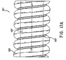
- the elongate tubes can include a first elongate member comprising a hollow body spirally wound to form at least in part a conduit having a longitudinal axis, a lumen extending along the longitudinal axis, and a hollow wall surrounding the lumen.
- the elongate tubes can include a second elongate member spirally wound and joined between adjacent turns of the first elongate member, the second elongate member forming at least a portion of the lumen of the elongate tube.
- the first elongate member may form in longitudinal cross-section a plurality of bubbles with a flattened surface at the lumen. Adjacent bubbles may be separated by a gap above the second elongate member. Adjacent bubbles may not be directly connected to each other. In certain implementations, the plurality of bubbles has perforations.
- Described herein are systems and methods for providing heat to a segmented inspiratory limb in a breathing circuit of a respiratory humidification system. It will be understood that although much of the description herein is in the context of segmented inspiratory limbs in breathing circuits, one or more features of the present disclosure can also be implemented in other scenarios where it is desirable to provide differential heating in segmented gas delivery conduits such as in respiratory, surgical, or other applications.
- the disclosure references heater wires, heating elements, and/or heaters in the context of providing heat to a conduit.
- Heater wire for example, is a broad term and is to be given its ordinary and customary meaning to a person of ordinary skill in the art (that is, it is not to be limited to a special or customized meaning) and includes, without limitation, heater strips and/or conductive elements that produce heat when electrical power is provided. Examples of such heating elements include wires made of a conductive metal (e.g., copper), conductive polymers, conductive inks printed on a surface of a conduit, conductive materials used to create a track on a conduit, and the like.
- the disclosure references conduits, limbs, and medical tubes in the context of gas delivery.
- Tube for example, is a broad term and is to be given its ordinary and customary meaning to a person of ordinary skill in the art and includes, without limitation, passageways having a variety of cross-sections such as cylindrical and non-cylindrical passageways. Certain embodiments may incorporate a composite tube, which may generally be defined as a tube comprising two or more portions, or, specifically, in some embodiments, two or more components, as described in greater detail below.
- the segmented limbs comprising the disclosed medical tubes can also be used in breathing circuits such as a continuous, variable, or bi-level positive airway pressure (PAP) system or other form of respiratory therapy.
- PAP bi-level positive airway pressure
- conduit and limb should be construed in a manner that is similar to tube.
- a heated, humidified breathing tube When a heated, humidified breathing tube is used for an incubator (or any region where there is a temperature change, such as around radiant warmers used for burn victims, or under a blanket used by a patient), the breathing tube will pass through at least two distinct zones: a lower temperature zone (such as the one outside the incubator) and a higher temperature zone (such as the one inside the incubator). If the tube is heated along its full length, one of the zones will tend to be at an undesirable, unsuitable, or non-optimal temperature, depending on which zone is sensed (e.g., which zone contains a temperature sensor). If the heater wire is controlled to a sensor inside the incubator (such as to a patient-end temperature sensor), the section outside the incubator will tend to be too cool, which can lead to condensation.
- a sensor inside the incubator such as to a patient-end temperature sensor
- the present disclosure describes systems and methods that provide for control over heat in a segmented breathing tube wherein each segment has an associated sensor providing feedback to a control module.
- a segmented breathing tube wherein each segment has an associated sensor providing feedback to a control module.
- segments of the breathing tube may be heated based at least in part on three different temperature sensors in the zones.
- the embodiments disclosed herein can control the heat delivered to a breathing tube based on a parameter at the patient-end, bypassing or ignoring one or more of the sensors at intermediate points along the tube. Moreover, the embodiments disclosed herein can control the heat delivered to a breathing tube using parameters provided by sensors including, for example and without limitation, temperature sensors, humidity sensors, flow sensors, oxygen sensors, and the like.
- a control module can monitor and control the heating temperatures in multiple zones or sections.
- the control module can be configured to provide heat to a first section of the breathing tube in a first mode and to the entire breathing tube in a second mode using embodiments of connector assemblies described herein.
- the embodiments described herein can be used without flying leads, exposed connectors, and/or patient-end electrical connections. Flying leads as used herein include electrical connections that extend externally of the breathing tubes, internally through the breathing tubes, and incorporated, molded, or otherwise formed or included as part of the breathing tubes.
- the control module can be located within the humidifier or externally to it.
- the controller is located within the humidifier to control the heater wires associated with a first segment of an inspiratory limb, a second segment of an inspiratory limb, and an expiratory limb as well as read parameters from sensors associated with the first and second segments of the inspiratory limb and/or the expiratory limb.
- the control module can also adaptively change the temperature for the segments.
- the control module can monitor temperature sensors associated with one or more segments.
- the monitoring can be continuous, based on intervals, or other schemes such as interrupt or event-based monitoring.
- the monitoring of temperature sensors can be based on reading values from an analog to digital converter, determining a voltage or current, sensing a logic condition, reading thermostatic devices, measuring thermistor values, measuring resistance temperature detectors, measuring the voltage of a thermocouple, or other methods for sensing temperature, including, but not limited to the use of semiconductor junction sensor, infrared or thermal radiation sensors, thermometers, indicators, or the like.
- the temperature sensors are thermistors.
- the ratio of the power delivered to the first segment of the inspiratory limb and the second segment of the inspiratory limb can change during use based at least in part on feedback from sensors associated with each segment.
- the ratio of power can be changed in a manner such that each segment is heated to a temperature to reduce or eliminate condensation.
- the ratio of power can be changed so that overheated gas is not provided to the patient.
- the ratio of power can be continuously changed based on feedback from sensors (e.g., temperature sensors, humidity sensors, oxygen sensors, flow sensors, etc.). The ratio of power can be changed in different ways.
- the ratio of power can be changed by altering the amplitude of a power signal (including, without limitation, the voltage and/or current), the duration of the power signal, the duty cycle of the power signal, or other suitable changes to the power signal.
- the ratio of power is changed by altering the magnitude of the current provided.
- an inspiratory limb comprising heater wires that are not within the gas path, but are contained within a material that separates them from the gas path and that also insulates them from an external environment.
- the circuitry used to provide power to heater wires in the segments and to read the sensors is internal to the inspiratory limb such that it is not exposed to the external environment.
- the heater wire is molded into the inspiratory or expiratory tube such that the ends of the heater wires in complementary segments of the tube contact an intermediate connector such that the heater wires electrically couple to the intermediate connector, wherein the intermediate connector can be configured to provide circuitry for heater wire control and/or sensor readings.
- a duty cycle of a power source applied to a heater wire can be modified or varied to alter an amount of heat delivered to a gas as it flows along the associated segment.
- a respiratory humidification system configured to deliver warm, humidified gas to a patient or other user.
- the gas is passed through a liquid chamber which is filled with a liquid (e.g., water) that is heated using a heater plate.
- the liquid evaporates in the chamber and combines with the gas which flows over it, thereby heating and/or humidifying the gas.
- the humidified gas can be directed to an inspiratory limb having one or more heater wires associated therewith.
- the heater wires can be selectively powered to provide a defined, desired, appropriate, or selected amount of heat to the humidified gas.
- the respiratory humidification system can be used in conjunction with an incubator or radiant warmer.
- the inspiratory limb can be segmented such that a first segment is outside the incubator and a second segment is inside the incubator. Furthermore, a first set of heater wires can be associated with the first segment and a second set of heater wires can be associated with the second segment.
- the humidification system can be configured to provide power to the first set of heater wires in a first mode and to the first set and second set of heater wires in a second mode. In some embodiments, the humidification system can be configured to provide power to the first set of heater wires in a first mode and to the second set of heater wires in a second mode.
- the inspiratory limb can include sensors at the end of each segment to provide feedback to the humidification system for use in selecting a power to deliver to the sets of heater wires in the segments.
- the humidification system can include an expiratory limb having associated heater wires which are also selectively controlled by the humidification system.
- the segmented limb is described with reference to an inspiratory limb. However, the described features can be applied to an expiratory limb as well.
- FIG. 1 illustrates an example respiratory humidification system 100 for delivering humidified gas to a user, the respiratory humidification system 100 having a breathing circuit 200 that includes a segmented inspiratory limb 202 with sensors 204a, 204b in each segment.
- the segmented inspiratory limb 202 can be used in conjunction with an incubator 208, as illustrated, or with another system where there are different temperatures along different segments of the inspiratory limb 202, such as in conjunction with a radiant warmer.
- the segmented inspiratory limb 202 can be used to provide different levels of heat to different segments of the inspiratory limb 202a, 202b to reduce or prevent condensation and/or to control a temperature of gas delivered to a user.
- the illustrated respiratory humidification system 100 comprises a pressurized gas source 102.
- the pressurized gas source 102 comprises a fan, blower, or the like.
- the pressurized gas source 102 comprises a ventilator or other positive pressure generating device.
- the pressurized gas source 102 comprises an inlet 104 and an outlet 106.
- the pressurized gas source 102 provides a flow of fluid (e.g., oxygen, anesthetic gases, air or the like) to a humidification unit 108.
- the fluid flow passes from the outlet 106 of the pressurized gas source 102 to an inlet 110 of the humidification unit 108.
- the humidification unit 108 is shown separate of the pressurized gas source 102 with the inlet 110 of the humidification unit 108 connected to the outlet 106 of the pressurized gas source 102 with a conduit 112.
- the pressurized gas source 102 and the humidification unit 108 can be integrated into a single housing.
- the illustrated humidification unit 108 is a pass-over humidifier that comprises a humidification chamber 114 and an inlet 110 to the humidification chamber 114.
- the humidification chamber 114 comprises a body 116 having a base 118 attached thereto.
- a compartment can be defined within the humidification chamber 116 that is adapted to hold a volume of liquid that can be heated by heat conducted or provided through the base 118.
- the base 118 is adapted to contact a heater plate 120.
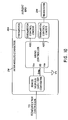
- the heater plate 120 can be controlled through a controller 122 or other suitable component such that the heat transferred into the liquid can be varied and controlled.
- the controller 122 of the humidification unit 108 can control operation of various components of the respiratory humidification system 100. While the illustrated system is illustrated as using a single controller 122, multiple controllers can be used in other configurations. The multiple controllers can communicate or can provide separate functions and, therefore, the controllers need not communicate.
- the controller 122 may comprise a microprocessor, a processor, or logic circuitry with associated memory or storage that contains software code for a computer program. In such implementations, the controller 122 can control operation of the respiratory humidification system 100 in accordance with instructions, such as contained within the computer program, and also in response to internal or external inputs.
- the controller 122, or at least one of the multiple controllers can be located with the breathing circuit, either attached to the breathing circuit or integrated as part of the breathing circuit.
- the body 116 of the humidification chamber 114 comprises a port 124 that defines the inlet 110, and a port 126 that defines an outlet 128 of the humidification chamber 114.
- a port 124 that defines the inlet 110
- a port 126 that defines an outlet 128 of the humidification chamber 114.
- the respiratory humidification system 100 includes a breathing circuit 200 comprising the inspiratory limb 202 connected to the outlet 128 that defines the outlet port 126 of the humidification unit 108.
- the inspiratory limb 202 conveys toward a user the mixture of gases and water vapor that exits the humidification chamber 114.
- the inspiratory limb 202 can include a heating element 206 positioned along the inspiratory limb 202, wherein the heating element 206 is configured to reduce condensation along the inspiratory limb 202, to control a temperature of gas arriving at the user, to maintain humidity of the gas, or any combination of these.
- the heating element 206 can raise or maintain the temperature of the gases and water vapor mixture being conveyed by the inspiratory limb 202.
- the heating element 206 can be a wire that defines a resistance heater.
- the respiratory humidification system 100 can be used in conjunction with an incubator 208.
- the incubator 208 can be configured to maintain a desired environment for a user within the incubator 208, such as a selected, defined, or desired temperature. Within the incubator 208, therefore, an interior ambient temperature may be different than a temperature outside the incubator 208.
- the incubator 208 causes, defines, creates, or maintains different temperature zones along the inspiratory limb 202, where the interior temperature is typically hotter than the exterior temperature. Having at least two different temperature zones along the inspiratory limb 202 can create problems during delivery of gas to a user such as condensation along the inspiratory limb 202, delivering a gas that has a temperature that is too high, or both.
- the respiratory humidification system 100 can include an expiratory limb 210 with associated heating element 212.
- the expiratory limb 210 and the inspiratory limb 202 can be connected using a suitable fitting (e.g., a wye-piece).
- the respiratory humidification system 100 can be used in conjunction with a radiant warmer, under a blanket, or in other systems or situations that create two or more temperature zones. The systems and methods described herein can be used with such systems and are not limited to implementations incorporating incubators.
- the inspiratory limb 202 can be divided into segments 202a and 202b where a first segment 202a can be a portion of the inspiratory limb 202 that is outside the incubator 208 and a second segment 202b ( e.g., an incubator extension), can be a portion of the inspiratory limb 202 that is inside the incubator 208.
- the first and second segments 202a, 202b can be different lengths or the same length.
- the second segment 202b can be shorter than the first segment 202a, and, in certain implementations, the second segment 202b can be about half as long as the first segment 202a.
- the first segment 202a for example, can have a length that is at least about 0.5 m and/or less than or equal to about 2 m, at least about 0.7 m and/or less than or equal to about 1.8 m, at least about 0.9 m and/or less than or equal to about 1.5 m, or at least about 1 m and/or less than or equal to about 1.2 m.
- the second segment 202b can have a length that is at least about 0.2 m and/or less than or equal to about 1.5 m, at least about 0.3 m and/or less than or equal to about 1 m, at least about 0.4 m and/or less than or equal to about 0.8 m, or at least about 0.5 m and/or less than or equal to about 0.7 m.
- the segments of the inspiratory limb 202a, 202b can be coupled to one another to form a single conduit for gas delivery.
- the first segment 202a can include one or more first heater wires 206a and one or more first sensors 204a and can be used without the second segment 202b.
- the controller 122 can be configured to control the first heater wires 206a and read the first sensor 204a without the second segment 202b being coupled to the first segment 202a.
- the controller 122 can be configured to control the first and second heater wires 206a, 206b and read the first and second sensors 204a, 204b in their respective segments.
- the controller 122 can be configured to control the respective first and second heater wires 206a, 206b and to read the respective first and second sensors 204a, 204b when the second segment 202b is attached; and to control the first heater wires 206a and to read the first sensor 204a when the second segment 202b is not attached, without modification to the controller 122 or humidification unit 108.
- the same controller 122 and/or humidification unit 108 can be used whether the inspiratory limb 202 includes both the first and second segments 202a, 202b or only the first segment 202a.
- the controller 122 can be further configured to control the heater wires 212 in the expiratory limb 210 without modification to the controller 122 or humidification unit 108. Accordingly, the respiratory humidification system 100 can function with or without the second segment 202b attached and/or with or without the expiratory limb 210 attached.
- the first and second segments 202a, 202b are permanently joined together to form a single conduit for gas delivery.
- permanently joined can mean that the segments 202a, 202b are joined together in a manner that makes it difficult to separate the segments, such as through the use of adhesives, friction fits, over-molding, mechanical connectors, and the like.
- the first and second segments 202a, 202b are configured to be releasably coupled.
- the first segment 202a can be used for gas delivery without the second segment 202b, or the first and second segments 202a, 202b can be coupled together to form a single conduit for gas delivery.
- the first and second segments 202a, 202b can be configured such that they can be coupled together in only one configuration.
- the first segment 202a can have a defined chamber-end (e.g., an end closest to the chamber 114 or humidification unit 108 along a direction of the flow of the humidified gas to the patient) and a defined patient-end ( e.g., an end closest to the patient along a direction of the flow of the humidified gas to the patient) wherein the chamber-end is configured to couple to components at the chamber 114 and/or humidification unit 108.
- a defined chamber-end e.g., an end closest to the chamber 114 or humidification unit 108 along a direction of the flow of the humidified gas to the patient
- a defined patient-end e.g., an end closest to the patient along a direction of the flow of the humidified gas to the patient
- the second segment 202b can have a defined chamber-end and a defined-patient end wherein the chamber-end is configured to only couple to the patient-end of the first segment 202a.
- the chamber-end of the first segment 202a can be configured to not couple with either end of the second segment 202b.
- the patient-end of the first segment 202a can be configured to not couple with the patient-end of the second segment 202b.
- the patient-end of the second segment 202b can be configured to not couple with either end of the first segment 202a.
- the first and second segments 202a, 202b can be configured to be coupled in only one way to form a single conduit for gas delivery.
- the first and second segments 202a, 202b can be configured to be coupled in a variety of configurations.
- the first and second segments 202a, 202b can be configured to not include a defined patient-end and/or a defined chamber-end.
- the first and second segments 202a, 202b can be configured such that the patient-end and/or the chamber-end of the first segment 202a can couple to either the chamber-end or the patient-end of the second segment 202b.
- the first and second segments 202a, 202b can be configured such that the chamber-end and/or the patient-end of the second segment 202a can couple to either the chamber-end or the patient-end of the second segment 202b.
- the respiratory humidification system 100 can include an intermediate connector 214 that can be configured to electrically couple elements of the first and second segments 202a, 202b of the inspiratory limb 202.
- the intermediate connector 214 can be configured to electrically couple the heater wires 206a in the first segment 202a to the heater wires 206b in the second segment 202b to enable control of the heater wires 206a, 206b using the controller 122.
- the intermediate connector 214 can be configured to electrically couple the second sensor 204b in the second segment 202b to the first sensor 204a in the first segment to enable the controller 122 to acquire their respective outputs.
- the intermediate connector 214 can include electrical components that enable selective control of the heater wires 206a, 206b and/or selective reading of the sensors 204a, 204b.
- the intermediate connector 214 can include electrical components that direct power through the first heater wires 206a in a first mode and through the first and second heater wires 206a, 206b in a second mode.
- the electrical components included on the intermediate connector 214 can include, for example and without limitation, resistors, diodes, transistors, relays, rectifiers, switches, capacitors, inductors, integrated circuits, micro-controllers, microprocessors, RFID chips, wireless communication sensors, and the like.
- the intermediate connector 214 can be configured to be internal to the inspiratory limb 202 such that it is substantially shielded from external elements (e.g., less than 1% of the water, particulates, contaminates, etc. from an environment external to the inspiratory limb 202 contacts the intermediate connector 214).
- some of the electrical components on the intermediate connector 214 can be configured to be physically isolated from the humidified gas within the inspiratory limb 202 to reduce or prevent damage that may result from exposure to humidity.
- the intermediate connector 214 can include relatively inexpensive passive electrical components to reduce cost and/or increase reliability.
- the inspiratory limb 202 can include sensors 204a, 204b in respective segments of the inspiratory limb 202a, 202b.
- the first sensor 204a can be positioned near an end of the first segment 202a, close to the incubator 208 so that the parameter derived from the first sensor 204a corresponds to a parameter of the humidified gas entering the second segment 202b.
- the second sensor 204b can be positioned near an end of the second segment 202b so that the parameter derived from the second sensor 204b corresponds to a parameter of the humidified gas delivered to the patient or user.
- the output of the sensors 204a, 204b can be sent to the controller 122 as feedback for use in controlling power delivered to the heating elements 206a, 206b of the segments of the inspiratory limb 202a, 202b.
- one or both of the sensors 204a, 204b can be temperature sensors, humidity sensors, oxygen sensors, flow sensors, or the like.
- a temperature sensor can be any suitable type of temperature sensor including, for example and without limitation, a thermistor, thermocouple, digital temperature sensor, transistor, and the like.
- the parameters provided by or derived from the sensors can include, for example and without limitation, temperature, humidity, oxygen content, flow rate, or any combination of these or the like.
- the controller 122 can be configured to control the heater wires 206a and 206b, to receive feedback from the sensors 204a and 204b, to provide logic to control power to the heater wires 206a and 206b, to adjust control of the heater wires 206a and 206b in response to readings from the sensors 204a and 204b, to detect a presence of a second segment 202b of the inspiratory limb 202, to derive parameters from the readings from the sensors 204a and 204b, and the like.
- the controller 122 includes a power source configured to deliver electrical power to the heater wires.
- the power source can be a source of alternating current or direct current.
- the controller 122 can receive input from a heater plate sensor 130.
- the heater plate sensor 130 can provide the controller 122 with information regarding a temperature and/or power usage of the heater plate 120.
- the controller 122 can receive input from a flow sensor 132. Any suitable flow sensor 132 can be used and the flow sensor 132 can be positioned between ambient air and the humidification chamber 114 or between the pressurized gas source 102 and the humidification chamber 114. In the illustrated system, the flow sensor 132 is positioned on the inlet port 124 of the humidification chamber 114.
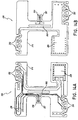
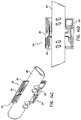
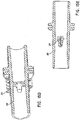
- FIG. 2 illustrates a portion of a segmented inspiratory limb 202 for use with a respiratory humidification system 100, the segmented inspiratory limb 202 comprising a first segment 202a and a second segment 202b and having an intermediate connector 214 configured to couple first heater wires 206a to second heater wires 206b and a first sensor 204a to a second sensor 204b in the respective segments 202a and 202b.
- Coupling the two segments 202a and 202b can comprise mechanically coupling the segments to form a single conduit through which humidified gases can be delivered to a user wherein mechanically coupling the segments 202a and 202b can result in electrically coupling the respective heater wires 206a, 206b and the respective sensors 204a, 204b through the intermediate connector 214.
- the segmented inspiratory limb 202 can comprise a structure 216 forming a lumen through which humidified gases can pass.
- the structure 216 can include paths formed within walls of the structure 216 configured to house heater wires 206a or 206b such that the heater wires 206a or 206b are shielded from the humidified gases travelling through the lumen and/or are covered by an external surface of the structure 216 so that they are not exposed.
- the structure 216 can be a spiral bubble tube wherein the heater wire paths are coils molded into the tube.
- the structure 216 can comprise any type of suitable material and can include insulating material and/or flexible material.
- the structure 216 and the intermediate connector 214 can be configured such that, when the first and second segments 202a and 202b are mechanically coupled, the heater wires 206a and 206b wrap over the intermediate connector 214 in such a way as to be electrically coupled to the intermediate connector 214.
- the first segment 202a and/or the intermediate connector 214 can exclude any flying leads for connecting to the second segment 202b, thereby facilitating connection of the second segment 202b to the first segment 202a.
- the structure 216 at complementary ends of the first and second segments 202a and 202b can be configured to house the intermediate connector 214.
- the intermediate connector 214 can be internal to the inspiratory limb 202.
- the complementary ends of the first and second segments 202a and 202b can be configured to shield the intermediate connector 214 from humidified gases travelling through the inspiratory limb 202.
- the intermediate connector 214 is both internal to the inspiratory limb 202 and shielded from humidified gases in the conduit, thereby reducing or eliminating exposure of electrical connections on the intermediate connector 214.
- the first heater wires 206a can comprise two wires 218 and 220 and the second heater wires 206b can comprise two wires 222 and 224.
- the two wires 218 and 220 in the first segment 202a can be electrically coupled to one another through electrical components 228 wherein the electrical coupling creates an electrical path through the wire 218, at least a portion of the electrical components 228, and the wire 220.
- the two wires 222 and 224 in the second segment 202b can be electrically coupled to one another through electrical components 228 and/or electrically shorted together at an end of the segment 202b opposite the intermediate connector 202b, such as through a patient-end connector (not shown) as described in greater detail herein with reference to FIGS.
- the intermediate connector 214 can be configured to allow a single controller to control power to the heater wires 206a, 206b, wherein the controller can be the humidifier controller 122 as described herein with reference to FIG. 1 .
- the humidifier controller 122 controls the heater wires without any additional control functionality located on the intermediate connector 214.
- the intermediate connector 214 can include passive components without any logic circuitry wherein the passive components direct power to heater wires 206a and/or 206b as selected by the controller 122. This can allow the intermediate connector 214 to be designed using relatively inexpensive components and can reduce the complexity of the design.
- heating of the two segments 202a and 202b can be accomplished using a maximum of four wires in each segment 202a, 202b.
- the four wires can include a first heater wire 218, a second heater wire 220, a signal sensor wire 228, and a return sensor wire 230.
- the four wires can include a first heater wire 222, a second heater wire 224, a signal sensor wire 232, and a return sensor wire 234.
- a controller can be configured to provide power independently to the first heater wires 206a and the second heater wires 206b and to read sensor data independently from the sensors 204a and 204b without including more than four wires in either segment 202a or 202b.
- control of the heater wires 206a and 206b and reading of the sensors 204a and 204b can be accomplished using less than four wires in each segment ( e.g., using 3 wires or using 2 wires) or using more than four wires in each segment ( e.g., using 5 wires, using 6 wires, using 7 wires, using 8 wires, or using more than 8 wires).
- the intermediate connector 214 can include electrical components 228 configured to allow a controller 122 to selectively control heater wires 206a, 206b.
- the controller 122 can be configured to control heating of the inspiratory limb 202 using two modes wherein a first control mode comprises providing power to the heater wires 206a in the first segment, and a second control mode comprises providing power to the heater wires 206a and 206b in the first and second segments 202a and 202b.
- the controller 122 can be configured to independently control heater wire sections.
- the control modes can include a mode where power is delivered only to the heater wires 206b in the second segment 202b.
- the controller 122 includes an electrical power source that provides electrical current. The first and second control modes can be based at least in part on the voltage supplied by the power source wherein a positive voltage or positive current can trigger the first control mode and a negative voltage or a negative current can trigger the second control mode.
- the power source provides rectified AC or DC power to the heater wires 206a, 206b and a change in the rectification or polarity triggers a change in the control mode.
- control of heating in the breathing circuit 200 can be accomplished with any power supply that can switch the polarity of the output signal.
- the amount of power provided to the heater wires 206a, 206b can be adjusted by adjusting a duty cycle of power applied to the heater wires 206a, 206b.
- PWM pulse-width modulation
- the duty cycle of the PWM signal can be adjusted to control the power delivered.
- the amount of power provided to the heater wires 206a, 206b can be adjusted by controlling the amplitude of the power signal.
- the intermediate connector 214 can include electrical components 230 configured to allow a controller 122 to selectively read sensors 204a, 204b. Selective reading can be accomplished through the use of a source of electrical current wherein applying a positive current across the wires 228 to 230 can result in the controller 122 measuring a signal from the first sensor 204a and applying a negative current across the wires 228 and 230 can result in the controller 122 measuring a signal from the second sensor 204b or from both the first and second sensors 204a, 204b, as described herein with reference to FIGS. 6A, 6B , and 7 .
- the controller 122 can use the readings from the sensors 204a, 204b to adjust power to the heater wires 206a, 206b, using, for example pulse-width modulation.
- the first sensor 204a can be positioned near the connection or intersection of the first and second segments 202a and 202b to provide to the controller 122 a parameter of gases entering the second segment 202b, which can correspond to entering an incubator or other such region having a different ambient temperature.
- the second sensor 204b can be positioned at a patient-end of the second segment 202b to provide to the controller 122 a parameter of gases delivered to the patient or a parameter of gases prior to the final piece before the patient, such as a wye-piece.
- the controller 122 can use these readings to adjust power to the heater wires 206a, 206b to maintain the temperature of the gas at the patient-end of the inspiratory limb 202 at a targeted or suitable temperature.
- the targeted or suitable temperature can vary depending at least in part on the application and environment it is being used in, and can be about 37°C, about 40 °C, at least about 37°C and/or less than or equal to about 38°C, at least about 36.5°C and/or less than or equal to about 38.5°C, at least about 36°C and/or less than or equal to about 39°C, at least about 35°C and/or less than or equal to about 40°C, at least about 37°C and/or less than or equal to about 41°C, or at least about 39.5°C and/or less than or equal to about 40.5°C.
- the second sensor 204b can be positioned inside the incubator but not attached to the breathing circuit. By measuring parameters inside the incubator, the temperature of the second segment 202b can be calculated,
- the controller 122 can independently control the amount of power delivered in the first and second control modes, as described herein. Based at least in part on feedback from the sensors 204a and/or 204b, the controller 122 can independently adjust power delivered in the first and second control modes, thereby resulting in varying heater power ratios between the first and second segments 202a and 202b.
- the first sensor 204a is positioned within the flow of gas within the inspiratory limb 202.
- the intermediate connector 214 or the first segment 202a can include a mechanical component that decreases turbulence in the flow of the gas across the first temperature sensor 204a which can increase accuracy in the readings of the sensor 204a.
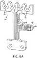
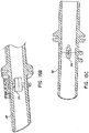
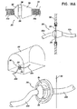
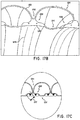
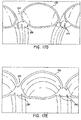
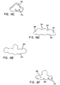
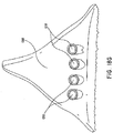
- the mechanical connector can have an aerodynamic cross section, examples of which are described for patient-end connectors with reference to FIGS. 15B-15E .
- the mechanical component e.g., a cross-member feature within the inspiratory conduit
- the mechanical component that decreases turbulence also secures the sensor 204a within the flow of the gases.
- the intermediate connector 214 and the mechanical component are configured to thermally isolate the sensor 204a from the electrical components on the intermediate connector 214, which may be advantageous where the sensor 204a is a temperature sensor, for example.
- the intermediate connector 214 includes additional connection points in addition to the connection points 26 illustrated in FIG. 2 .
- the additional connection points can be used to incorporate further functionality into the breathing circuit such as, for example, incorporating a memory device (PROM), a micro-controller, additional circuits, and the like.
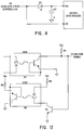
- FIG. 3A illustrates a circuit diagram of an example intermediate connector 214 including an active rectified power source for providing power to heater wires in a segmented inspiratory limb of a breathing circuit, wherein the circuit is configured to power heater wires R1 and R2 in a first segment of the inspiratory limb in a first mode and to power heater wires R1, R2, R3, and R4 in both segments in a second mode.
- the intermediate connector 214 By providing diodes D1 and D2 on the intermediate connector 214 and switches S1 and S2, power can be alternatively applied through heater wires R1 and R2, where the resistors represent the heater wires, or through heater wires R1, R2, R3, and R4.
- the power source is represented in the figure using VP and VN which correspond to terminals of a power supply.
- the voltage supply is an alternating current (AC) power supply.
- the power source can be a direct current (DC) power supply.
- D1 and D2 can include any of a plurality of different types of flow control devices such as, for example and without limitation, rectifiers, transistors, relays, switches, triacs, mosfets, thyristors (SCR), thermostats, and the like.
- the switches S1 and S2 switch between the VP and VN terminals of the power source.
- switches S1 and S2 are switched every half-cycle of an AC power cycle so that approximately equal current is drawn from the power source during every half cycle.
- the circuit illustrated in FIG. 3A can be used to control the heaters R1, R2, R3, and R4 in two control modes, wherein a first control mode corresponds to providing power only to R1 and R2, and a second control mode corresponds to providing power to R1, R2, R3 and R4.
- switch S1 To provide power only to the heaters R1 and R2 in the first segment 202a (corresponding to the first control mode), switch S1 connects to VP and switch S2 connects to VN during a positive cycle from the power source, and switch S1 connects to VN and switch S2 connects to VP during a negative cycle from the power source.
- switch S1 connects to VN and switch S2 connects to VP during a positive cycle from the power source, and switch S1 connects to VP and switch S2 connects to VN during a negative cycle from the power source.
- switch S1 connects to VP and switch S2 connects to VN during a negative cycle from the power source.
- current flows through R1, R2, R3, R4 and D2 while D1 prevents current from shorting across the wires to bypass heaters R3 and R4. Switching of switches S1 and S2 can be accomplished through hardware or software that adds logic to the system, as described herein with reference to FIG. 5 .
- switching of switches S1 and S2 is performed at the zero crossing of an AC power cycle. In some embodiments, the falling and rising edges of zero crossing circuitry are not delayed by the same amount and the circuit is not active near the zero crossing. Thus, the switching of switches S1 and S2 can be performed with or without zero-crossing switching detection and/or logic.
- the diodes D1 and D2 can dissipate power in the circuit, and therefore generate heat.
- Schottky diodes can be used where it is desirable to reduce power dissipation in relatively high-temperature environments. Schottky diodes can be operated near a maximum junction temperature to reduce or minimize power dissipation, which may be desirable in certain implementations of the respiratory humidification system described herein.
- the heat generated by the diode can influence temperature readings of the sensor 204a. To reduce this influence, the diodes can be thermally connected to an airflow path of the circuit.
- a heat sink or pad can be included on the intermediate connector 214 that is thermally coupled to the ambient environment.
- the sensor 204a e.g., a thermistor or other temperature sensor
- the sensor 204a can be thermally insulated from the components and physically located relatively far from the other components, as described with reference to FIGS. 14A-B , and 15 .
- FIG. 3B illustrates another circuit diagram of an example intermediate connector 214 including an active rectified power source for providing power to heater wires in a segmented inspiratory limb of a breathing circuit, wherein the circuit is configured to power heater wires R1 and R2 in a first segment of the inspiratory limb in a first mode and to power heater wires R1, R2, R3, and R4 in both segments in a second mode.
- the circuit is configured to power heater wires R1 and R2 in a first segment of the inspiratory limb in a first mode and to power heater wires R1, R2, R3, and R4 in both segments in a second mode.
- only diode D1 may be provided and the path of power through heater wires R1 and R2 or through heater wires R1 through R4 can still be controlled, as previously described with respect to FIG. 3A .
- the diode D2 that was shown in the circuit of FIG. 3A is eliminated.
- FIG. 3B having only one diode D1, can result in less heat generated by the circuit, reduced parts costs, and a smaller circuit board.
- the remaining portions of the circuit shown in FIG. 3B operate in a manner that is similar to the description of FIG. 3A .
- most of the current flows through R1, R2 and D1 with only residual current flowing through R3 and R4.
- the residual current through R3 and R4 can be negligible such that it does not affect the performance of the humidification system.
- Switches S1 and S2 can be switched based at least in part on, for example, time, an output current of the supply, feedback from sensors, or other control inputs.
- the circuits illustrated in FIGS. 3A or 3B also can be used to control the heaters R1, R2, R3, and R4 in two control modes, wherein a first control mode corresponds to providing power only to R1 and R2, and a second control mode corresponds to providing power to R1 through R4.
- switch S1 To provide power only to the heaters R1 and R2 in the first segment 202a (corresponding to the first control mode), switch S1 connects to VP and switch S2 connects to VN. In the first control mode, current flows through R1, R2, and D1. D2 prevents current from flowing through R3 and R4 in the circuit shown in FIG. 3A . However, D2 is an optional component as shown in FIG. 3B . To provide power to the heaters R1, R2, R3, and R4 in the first and second segments 202a, 202b (corresponding to the second control mode), switch S1 connects to VN and switch S2 connects to VP.
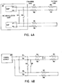
- FIG. 1 also illustrates an example respiratory humidification system 100 having an inspiratory limb 202 and an expiratory limb 210, wherein the humidification system 100 is configured to control heater wires 206, 212 in both limbs.
- heater wires 212 in the expiratory limb 210 can be electrically coupled to the inspiratory heater wires 206 outside the humidification unit 108 and controller 122 so that control of the expiratory heater wires 212 can be implemented without affecting other control modes and without additional switching transistors.
- the expiratory heater wires 212 can be electrically coupled to the inspiratory heater wires 206 within the humidification unit 108.
- connection of the expiratory heater wires 212 to the inspiratory heater wires 206 can be done in the humidification system 108, on the intermediate connector 214, in a sensor cartridge at the humidification system 108, or the like.
- the controller 122 can control the expiratory heater wires 212 with no additional electrical connections at the patient end, the presence of which may increase risk, system complexity, and cost. Examples of electrical coupling of the expiratory heater wires 212 and the inspiratory heater wires 206 inside the humidification unit 108 are shown in FIGS. 4A-4D , 8A , and 8B .
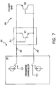
- the humidification unit 108 can incorporate switches or relays S3 and S4 to select between independent and dependent control of the inspiratory heater wires and the expiratory heater wires.
- the switches or relays are activated when a tube (e.g., an inspiratory limb or an expiratory limb) with an appropriate identification is connected to the humidification unit 108, such as through an identification resistor detected and/or measured by the humidification unit 108.
- a tube e.g., an inspiratory limb or an expiratory limb
- the switches are not activated (e.g., both switches S3, S4 are open)
- the heater wires in the inspiratory limb and/or the heater wires in the expiratory limb can be individually and/or independently controlled.
- the humidification unit 108 can include an inspiratory power source INSP and an expiratory power source EXP, wherein the system can implement switching in each power source as described herein with reference to FIGS. 3A and 3B .
- the inspiratory power source can have switches S1 and S2 configured to selectively direct positive and negative cycles to the heaters R1 through R4.
- the expiratory power source EXP can include switches configured to selectively direct power to the expiratory limb having heaters R5 and R6.
- both switches in expiratory power source EXP can be opened such that power is provided to the inspiratory heater wires and the expiratory heater wires by the inspiratory power source INSP.
- the humidification unit 108 does not include an expiratory power source EXP.
- the inspiratory power source INSP is used to provide power to the inspiratory heater wires when the switches S3 and S4 are open and to provide power to both the inspiratory and expiratory heater wires when the switches S3 and S4 are closed.
- the inspiratory limb heater wires 206 can be controlled in the same way as before, but now the system can use the switches S3, S4 to simultaneously control power to the expiratory heater wires 212 and the inspiratory heater wires 206 using a unified electrical circuit and/or control system.
- the humidification unit 108 can operate in two modes relative to the inspiratory limb 202 (e.g., the first mode being where the humidification unit 108 provides power to the heaters R1 and R2 and the second mode being where it provides power to the heaters R1 to R4) while selectively controlling power to the heaters R5 and R6 in the expiratory limb such that the humidification unit 108 can provide no power to the heaters R5 and R6, or provide power to the heaters R5 and R6 while operating in the first mode, in the second mode, or in both modes.
- a connection between the inspiratory limb 202 and expiratory limb 210 can be made internal or external to the humidification unit 108. In an embodiment, the connection is made in a sensor cartridge, the intermediate connector 214, or in another location.
- an expiratory circuit configured to connect the expiratory heater wires 212 to the controller 122 can be implemented at the intermediate connector 214 shown on FIG. 1 .
- the expiratory circuit can be connected in one or more of several ways.
- the expiratory circuit can be connected in parallel with the heater wires 206a in the first segment 202a or with the heater wires 206b in the second segment 202b.
- the intermediate connector 214 can include an internal fly lead making the expiratory circuit available on the intermediate connector 214.
- the intermediate connector 214 can be connected to an added third channel to so that there are no fly leads between the inspiratory and expiratory circuits.
- a heater wire driver control circuit can be added to the controller 122 to accommodate such embodiments.
- FIG. 4B illustrates an example embodiment of a humidification system incorporating a power supply 405 to provide power to both the inspiratory heater wires R1 to R4 and the expiratory heater wires R5 and R6 through a combination of switches or relays S1 to S6 and diode D1.
- the humidification system is configured to provide power to the expiratory heater wires when only the inspiratory heater wires R1, R2 in the first segment of the inspiratory limb are receiving power ( e.g., in a first operation mode) or when the inspiratory heater wires R1 to R4 in both segments are receiving power ( e.g., in a second operation mode).
- the power supply 405 can be any suitable power supply including, for example, a power supply which provides alternating current in a sine wave, sawtooth, square wave, or other form.
- the power supply 405 is a transformer which provides an alternating current signal with a voltage of at least about 22 VAC, at least about 5 VAC or less than or equal to about 30 VAC, at least about 10 VAC or less than or equal to about 25 VAC, at least about 12 VAC or less than or equal to about 22 VAC.
- the humidification system can be configured to provide power to the expiratory heater wires R5, R6 in the first operation mode while the power supply 405 is providing power in a negative cycle.
- switches S1, S2, S5, S6 close and switches S3, S4 open.
- the current flows from the negative terminal of the power supply 405 through switch S2 and branches to provide power to the heater wires in both the inspiratory limb and the expiratory limb.
- the current flows to inspiratory heater wire R2, then through diode D1 to inspiratory heater wire R1, and then returns to the positive terminal on the power supply 405 through switch S1.
- the current flows through switch S6 to expiratory heater wire R5, then to expiratory heater wire R6, and then returns to the positive terminal on the power supply 405 through switches S5 and S1.
- the humidification system can be configured to provide power to the expiratory heater wires R5, R6 in the first operation mode while the power supply 405 is providing power in a positive cycle.
- switches S3, S4, S5, S6 close and switches S1, S2 open.
- the current flows from the positive terminal of the power supply 405 through switch S3 and branches to provide power to the heater wires in both the inspiratory limb and the expiratory limb.
- the current flows through switch S6 to inspiratory heater wire R2, then through diode D1 to inspiratory heater wire R1, and then returns to the negative terminal on the power supply 405 through switches S5 and S4.
- the current flows to expiratory heater wire R5, then to expiratory heater wire R6, and then returns to the negative terminal on the power supply 405 through switch S4.
- the humidification system can be configured to provide power to the expiratory heater wires R5, R6 in the second operation mode while the power supply 405 is providing power in a positive cycle.
- switches S1, S2, S5, S6 close and switches S3, S4 open.
- the current flows from the positive terminal of the power supply 405 through switch S1 and branches to provide power to the heater wires in both the inspiratory limb and the expiratory limb.
- the current flows to inspiratory heater wire R1, then bypasses diode D1 to flow to inspiratory heater wire R3, then to inspiratory heater wire R4, then to inspiratory heater wire R2, and then returns to the negative terminal on the power supply 405 through switch S2.
- the current flows through switch S5 to expiratory heater wire R6, then to expiratory heater wire R5, and then returns to the negative terminal on the power supply 405 through switches S6 and S2.
- the humidification system can be configured to provide power to the expiratory heater wires R5, R6 in the second operation mode while the power supply 405 is providing power in a negative cycle.
- switches S3, S4, S5, S6 close and switches S1, S2 open.
- the current flows from the negative terminal of the power supply 405 through switch S4 and branches to provide power to the heater wires in both the inspiratory limb and the expiratory limb.
- the current flows through switch S5 to inspiratory heater wire R1, then bypasses diode D1 to flow to inspiratory heater wire R3, then to inspiratory heater wire R4, then to inspiratory heater wire R2, and then returns to the positive terminal on the power supply 405 through switches S6 and S3.
- the current flows to expiratory heater wire R6, then to expiratory heater wire R5, and then returns to the positive terminal on the power supply 405 through switch S3.
- FIG. 4C illustrates an example embodiment of a humidification system incorporating a power supply 405 to provide power to both the inspiratory heater wires R1 to R4 and the expiratory heater wires R5 and R6 through a combination of switches or relays S1 to S6 and diodes D1, D2.
- the humidification system is configured to provide power to the expiratory heater wires only when the inspiratory heater wires R1, R2 in the first segment of the inspiratory limb are receiving power ( e.g., only in the first operation mode).
- the humidification system can be configured to provide power to the expiratory heater wires R5, R6 in the first operation mode while the power supply 405 is providing power in a negative cycle.
- switches S1, S2, S5, S6 close and switches S3, S4 open.
- the current flows from the negative terminal of the power supply 405 through switch S2 and branches to provide power to the heater wires in both the inspiratory limb and the expiratory limb.
- the current flows to inspiratory heater wire R2, then through diode D1 to inspiratory heater wire R1, and then returns to the positive terminal on the power supply 405 through switch S1.
- the current flows through switch S6 and through diode D2 to expiratory heater wire R5, then to expiratory heater wire R6 and then returns to the positive terminal on the power supply 405 through switches S5 and S1.
- the humidification system can be configured to provide power to the expiratory heater wires R5, R6 in the first operation mode while the power supply 405 is providing power in a positive cycle.
- switches S3, S4, S5, S6 close and switches S1, S2 open.
- the current flows from the positive terminal of the power supply 405 through switch S3 and branches to provide power to the heater wires in both the inspiratory limb and the expiratory limb.
- the current flows through switch S6 to inspiratory heater wire R2, then through diode D1 to inspiratory heater wire R1, and then returns to the negative terminal on the power supply 405 through switches S5 and S4.
- the current flows through diode D2 to expiratory heater wire R5, then to expiratory heater wire R6, and then returns to the negative terminal on the power supply 405 through switch S4.
- the humidification system can be configured to provide power only to the inspiratory heater wires R1 to R4 (and not to provide power to the expiratory heater wires R5, R6) in the second operation mode while the power supply 405 is providing power in a positive cycle.
- switches S1, S2, S5, S6 close and switches S3, S4 open.
- the current flows from the positive terminal of the power supply 405 through switch S1 to inspiratory heater wire R1, the current then bypasses diode D1 and flows to inspiratory heater wire R3, to inspiratory heater wire R4, to inspiratory heater wire R2 and back to the negative terminal on the power supply 405 through switch S2.
- the current does not flow through the expiratory heater wires because of diode D2 which blocks the flow of current through that circuit on a positive cycle with the switches configured as described.
- the humidification system can be configured to provide power only to the inspiratory heater wires R1 to R4 (and not to provide power to the expiratory heater wires R5, R6) in the second operation mode while the power supply 405 is providing power in a negative cycle.
- switches S3, S4, S5, S6 close and switches S1, S2 open.
- the current flows from the positive terminal of the power supply 405 through switches S4 and S5 to inspiratory heater wire R1, the current then bypasses diode D1 and flows to inspiratory heater wire R3, to inspiratory heater wire R4, to inspiratory heater wire R2 and back to the negative terminal on the power supply 405 through switches S6 and S3.
- the current does not flow through the expiratory heater wires because of diode D2 which blocks the flow of current through that circuit on a negative cycle with the switches configured as described.
- FIG. 4D illustrates an example embodiment of a humidification system incorporating a power supply 405 to provide power to both the inspiratory heater wires R1 to R4 and the expiratory heater wires R5 and R6 through a combination of switches or relays S1 to S6 and diode D1 with the expiratory heater wires R5, R6 being electrically coupled to the inspiratory heater wires R1 to R4 on a patient-side of the heater wires in the first segment of the inspiratory limb, which can occur an intermediate connector, such as any of the intermediate connectors described herein.
- a power supply 405 to provide power to both the inspiratory heater wires R1 to R4 and the expiratory heater wires R5 and R6 through a combination of switches or relays S1 to S6 and diode D1 with the expiratory heater wires R5, R6 being electrically coupled to the inspiratory heater wires R1 to R4 on a patient-side of the heater wires in the first segment of the inspiratory limb, which can occur an
- the expiratory heater wires R5, R6 are coupled to the inspiratory heater wires R1 to R4 at the intermediate connector, but any suitable location after the inspiratory heater wires in the first segment can be used for coupling the heater wires in the inspiratory and expiratory limb.
- the humidification system is configured to provide power to the expiratory heater wires only when the inspiratory heater wires R1 to R4 in both segments of the inspiratory limb are receiving power ( e.g., only in the second operation mode).
- the humidification system can be configured to provide power to the inspiratory heater wires R1 to R4 and to the expiratory heater wires R5, R6 in the second operation mode while the power supply 405 is providing power in a positive cycle.
- switches S1, S2, S5, S6 close and switches S3, S4 open.
- the current flows from the positive terminal of the power supply 405 through switch S1 to inspiratory heater wire R1, then bypasses diode D1 and branches to provide power to the heater wires in both the second segment of the inspiratory limb and the expiratory limb.
- the current flows to inspiratory heater wire R3, then to inspiratory heater wire R4, returning to the intermediate connector.
- current flows to R5 and then to R6, returning back to the intermediate connector.
- the current then flows through inspiratory heater wire R2 and then returns to the negative terminal on the power supply 405 through switch S2.
- the humidification system can be configured to provide power to the expiratory heater wires R5, R6 in the second operation mode while the power supply 405 is providing power in a negative cycle.
- switches S3, S4, S5, S6 close and switches S1, S2 open.
- the current flows from the negative terminal of the power supply 405 through switches S4 and S5 to inspiratory heater wire R1, then bypasses diode D1 and branches to provide power to the heater wires in both the second segment of the inspiratory limb and the expiratory limb.
- the current flows to inspiratory heater wire R3, then to inspiratory heater wire R4, returning to the intermediate connector.
- current flows to R5 and then to R6, returning back to the intermediate connector.
- the current then flows through inspiratory heater wire R2 and then returns to the positive terminal on the power supply 405 through switches S6 and S3.
- the humidification system can be configured to provide power only to the inspiratory heater wires R1 and R2 in the first segment of the inspiratory limb (and not to provide power to the expiratory heater wires R5, R6) in the first operation mode while the power supply 405 is providing power in a negative cycle.
- switches S1, S2, S5, S6 close and switches S3, S4 open.
- the current flows from the negative terminal of the power supply 405 through switch S2 to inspiratory heater wire R2, the current then flows through diode D1 to inspiratory heater wire R1, and then returns to the positive terminal on the power supply 405 through switch S1.
- the humidification system can be configured to provide power only to the inspiratory heater wires R1 and R2 in the first segment of the inspiratory limb (and not to provide power to the expiratory heater wires R5, R6) in the first operation mode while the power supply 405 is providing power in a positive cycle.
- switches S3, S4, S5, S6 close and switches S1, S2 open.
- the current flows from the positive terminal of the power supply 405 through switches S3 and S6 to inspiratory heater wire R2, the current then flows through diode D1 to inspiratory heater wire R1, and returns back to the negative terminal on the power supply 405 through switches S5 and S4.
- FIG. 5 illustrates a block diagram of an example system 500 configured to detect a presence of an extension of an inspiratory limb using extension detect module 502 and to provide power to heater wires in the inspiratory limb (e.g., a first segment of the inspiratory limb), the extension of the inspiratory limb ( e.g., a second segment of the inspiratory limb), and/or an expiratory limb.
- the logic module 504 which can comprise hardware, software, or some combination of both, can be configured to provide the logic that enables the switching described for the different control modes, as described with reference to, for example, FIGS. 3A, 3B , 4 , 8A , and 8B .
- the logic module 504 can receive signals from an integrated circuit 506 that is part of the respiratory humidification system 100.
- the logic module 504 is software embedded wholly or partially within the integrated circuit 506 which converts signals from the integrated circuit 506.
- the combination of the logic module 504 and the integrated circuit 506 can be configured to detect a zero-level crossing, or where voltage or current transitions from positive to negative or vice versa, and to change states of switches according to a control mode.
- the logic module 504 can output PWM signals 508a, 508b according to a desired, selected, or defined power output where the PWM signal is delivered to the inspiratory heater wires (INSP HW), the expiratory heater wires (EXP HW), or both.
- INSP HW inspiratory heater wires
- EXP HW expiratory heater wires
- the system 500 can include an extension detect module 502 configured to detect whether the second segment 202b is connected to the breathing circuit 200.
- the extension detect module 502 can produce an "enable signal” if the second segment 202b is connected.
- the logic module 504 can receive the "enable signal” and adjust switching accordingly.
- the "enable signal” indicates to the logic module 504 that the system 500 will not control the inspiratory and expiratory circuits independently and simultaneously.
- the extension detect module 502 can be configured to detect the presence of the second segment 202b by switching on both the inspiratory and expiratory circuits and detecting whether a hardware overcurrent event is detected. If the overcurrent event is not detected when either are switched on individually but it is detected with they are both switched on together, the extension detect module 502 can produce an "enable signal" indicating that the second segment 202b is connected. In some embodiments, the extension detect module 502 can detect the presence of the second segment 202b by detecting a resistance of an identification resistor or of heater wires in each section using current measurements.
- the extension detect module 502 can produce an "enable signal" if current measurements for different cycles differ where different control modes are being implemented as described above with reference to FIGS. 3A, 3B , 4 , 8A , and 8B .
- FIGS. 6A and 6B illustrate example circuit diagrams in a respiratory humidification system 100, wherein the circuit 600 is configured to read data from two sensors R1 and R2.
- the sensors R1 and R2 are represented using resistors, but any suitable type of sensor can be used such as, for example and without limitation, temperature sensors, humidity sensors, flow sensors, oxygen sensors, and the like.
- the sensors can be temperature sensors such as thermistors.
- the sensors R1 and R2 respectively represent a first thermistor at the intermediate connector 214 and a second thermistor at a patient-end of the breathing circuit 200 (e.g., on a patient-end connector).
- the two thermistors R1 and R2 can be measured using two wires in the breathing circuit 200 using the circuit 600 in conjunction with a current or voltage source and switches in the humidifier controller 122. While the description with reference to FIGS. 6A and 6B involves thermistors, it is applicable to other suitable sensors which affect voltages and/or currents provided to circuits with which they are associated.
- the humidifier controller 122 sets the switch to connect the top current supply to ground. Current then flows from the bottom current supply through R2 and to ground through the switch. Current is blocked from going through R1 by diode D1.
- the humidifier controller 122 can be configured to measure the voltage drop from the bottom current supply to ground, and to derive the resistance of sensor R2 based at least in part on the supplied current and measured voltage.
- the humidifier controller 122 can read the patient-end sensor R2 and record the result. The humidifier controller 122 can then set the switch to connect the bottom current supply to ground.
- the humidifier controller 122 can be configured to measure the voltage drop from the top current supply to ground, and to derive the resistance of sensor R1 based at least in part on the supplied current, the measured voltage, and the recorded result from measuring the resistance of R2. In some embodiments, a voltage drop across D1 is accounted for in the derivation of the resistance of R1. In the embodiment illustrated in FIG. 6A , by placing D1 near R1, the temperature of the diode D1 can be calculated which can be used in the calculation of the voltage drop across D1.
- One potential advantage of the configuration illustrated in FIG. 6A is that the measurements of the sensor R2 at the patient end may be more accurate because the measurements are made without passing through a diode, as illustrated in the embodiment of FIG. 6B , which can introduce uncertainties or errors.
- an additional diode D2 can be added to the intermediate connector 214.
- the humidifier controller 122 can be configured to measure sensors R1 and R2 in a fashion similar to the embodiment illustrated in FIG. 6A and described above. A difference is that when measuring sensor R1, current flows through R1 and D1 and not through R2 because the diode D2 blocks current flow through R2. In this way, the measurement of sensor R1 can be substantially isolated or separated from the measurement of sensor R2. Similar to the derivation of the resistance of sensor R1, the voltage drop across the diode D2 can be accounted for in deriving the resistance of sensor R2. By placing D1 and D2 near R1, the temperature of the diodes can be calculated which can be used in the calculation of the voltage drops across D1 and D2, respectively.
- the measurement of sensors R1, R2 is performed in software running in a controller connected to the circuits of FIGS. 6A or 6B .
- the direction and amount of current supplied to the circuit can be controlled by such software.
- An accurate measurement of the resistance of sensors R1, R2 can be obtained by measuring the voltages using, for example, an analog to digital converter.
- the software can supply two different currents (I1 and I2) in the same direction. This will result in two different voltage readings (V1 and V2) corresponding to the two different currents (I1 and I2). Using these two voltages and currents, the software can solve for the voltage drop of the diodes D1, D2 and resistances for sensors R1, R2.
- the calculated Vdrop has a constant error from a measured Vdrop that is corrected in software.
- the Vdrop is increased by approximately 15% as an error compensation.
- FIG. 7 illustrates an example circuit diagram in the respiratory humidification system 100, wherein the circuit 700 is configured to read temperature data using two transistors Q1 and Q2 acting as temperature sensors.
- the temperature measurement can be based at least in part on a temperature effect of the pn-junction of the base and emitter terminals of the transistors.
- the switching of the current in the humidifier controller 122 can be the same as for the circuit described with reference to FIGS. 6A and 6B or it can be an alternate configuration, as shown.
- the illustrated switching configuration uses two switches with two power sources and two grounds to selectively provide electrical power to the wires.
- the top switch electrically connects a top power source to wire 702 and the bottom switch electrically connects the ground to wire 704.
- the top switch electrically connects the ground to wire 702 and the bottom switch electrically connects the bottom power source to wire 704.
- the diodes can be removed as the transistors provide the functionality of the temperature sensors and the diodes.
- FIG. 8A illustrates an example diagram of a hardware configuration 800 for a breathing circuit 200 having a first segment of an inspiratory limb 202a, a second segment of the inspiratory limb 202b, and an expiratory limb 210.
- the hardware configuration 800 can include a humidifier 108 configured to couple the wiring of the heater wires HW1 and HW2 through switches or relays S3 and S4, and the wiring for sensors 204a, 204b.
- the sensor cartridge 802 can be configured to couple the wiring of the heater wires HW1, HW2 and the wiring for sensors 204a, 204b.
- the switches S3, S4 can be used to selectively control power to the heater wires HW2 of the expiratory limb 210, as described with reference to FIG.
- the switches S3 and S4 both default to an open position, and are closed when an appropriate tube is connected to the humidifier 108 (e.g., an inspiratory limb or expiratory limb with an appropriate identification resistor).
- the hardware configuration 800 can be used to provide power to heater wires HW1 and/or to heater wires HW2.
- the heater wires HW1 can be controlled in two modes. In a first mode, the first heater wires 206a receive electrical power while the second heater wires 206b do not. In a second mode, the first and second heater wires 206a, 206b receive electrical power.
- heater wires HW2 are able to be powered when the heater wires HW1 are being controlled in either of the first or second modes. It is to be understood that the heater wires HW2 of the expiratory limb can be selectively controlled while the heater wires HW1 of the inspiratory limb remain in a single mode. For example, when the heater wires HW1 of the inspiratory limb are being controlled in a first mode (or a second mode), the heater wires HW2 of the expiratory limb can alternately receive or not receive power based at least in part on the operation of switches S3 and S4 without any change in control mode of the heater wires HW1. Similarly, the heater wires HW2 of the expiratory limb can remain receiving power while the heater wires HW1 of the inspiratory limb are changed between the first and second modes.
- the hardware configuration 800 can include an intermediate printed circuit board (PCB) 214 that includes two diodes, with one diode being a power diode D1 and another diode being a signal diode D3.
- the intermediate PCB 214 can include heat pads to dissipate heat generated by the diodes D1, D3 to reduce the effects on the sensor 204a.
- the hardware configuration 800 can include a patient-end PCB 804 having two heater wires and a sensor 204b, wherein the heater wires 206b are directly electrically coupled.
- electrical power can be provided to HW1 such that current flows through heater wires 206a and through diode D1 while substantially no current flows through heater wires 206b ( e.g., less than 1% of the current through heater wires 206a flows through heater wires 206b).
- electrical power can be provided to HW1 such that current flows through heater wires 206a and 206b.
- the first and second modes of operation can be controlled at least in part by the direction of the current flow through the heater wires HW1.
- diodes D2 and D4 can be added to hardware configuration 800, as shown in FIG. 8B .
- the software for the sensing circuit can be altered to account for increased heat.
- the signal diodes D3, D4 are positioned close to one another so they experience the same or similar ambient conditions to reduce differential effects caused by differing ambient temperatures.
- the circuit 200 otherwise operates in a manner similar to the circuit shown in FIG. 8A .
- removing diode D4 improves patient end sensing reliability. For example, diodes can fail in an open position. If diode D4 fails open, reading the patient end temperature may not be possible. In the circuit shown in FIG. 8A , if diode D3 fails, the patient-end sensor 204b can still be read. The removal of diode D2 can have similar advantages.
- the sensor cartridge 802 can be located within the humidification system 100 or external to the system.
- FIG. 9 illustrates an example embodiment of a respiratory humidification system 100 that utilizes a micro-controller in an intermediate connector 214 to measure data for controlling heating and to read sensor values in an inspiratory limb 202.
- one or more micro-controllers can be incorporated in a sensor cartridge, in the humidifier, in the intermediate connector 214, or in any combination of these.
- the micro-controller provides similar functionality as described herein when incorporated on the sensor cartridge, for example.
- the illustrated example embodiment uses one heater wire as a common reference, the wire connected to VN, and connects the two heater wires HW1, HW2 and the sensor wires to the common reference.
- the example embodiment also converts both sensors' 204a, 204b readings into a digital signal in the intermediate connector 214 to send to the humidifier controller 122. This can reduce or eliminate isolation issues by referencing the sensors 204a, 204b to a common reference point and by sending a digital parameter reading which can be passed through an optocoupler on the controller 122 which will isolate the signal, as described herein with reference to FIG. 12 .
- Using this example embodiment can allow for two independent channels of control to heat just the first section 202a or the first and second sections of the inspiratory limb 202a, 202b to provide a desired, selected, or defined heating control.
- FIG. 10 illustrates a block diagram of an intermediate connector 214 for an inspiratory limb 202, wherein the intermediate connector 214 uses a micro-controller.
- the micro-controller can be used to measure an analog signal from the thermistors 204a and 204b and convert the analog signal into a digital signal using analog-to-digital converters (ADCs).
- ADCs analog-to-digital converters
- the converted digital signal can be sent to the humidifier controller 122 on a single data line.
- the data line can be used to allow communication between the micro-controller and the humidifier controller 122 to provide temperature data.
- the data line can be used to provide power to the micro-controller by pulling the data line high on the humidifier controller 122 when data is not being sent.
- the power module and data line converter can include a capacitor and a diode so that the capacitor is charged when the data line is high.
- the charged capacitor can be used to power the micro-controller when the data line is being used for communication.
- the circuit diagram for an example power module and data line converter is illustrated in FIG. 11 .
- Temperature sensing using this configuration can be accomplished using a current source or a voltage source on the intermediate connector 214 to drive the thermistors so they can be read by the micro-controller. This can be done using, for example, transistors or an op-amp. Data line communication can be accomplished using a time-slot based approach where each logic level can be sent and read in a predefined time slot. In this way, one wire can be used to allow two-way communication between the humidifier controller 122 and the micro-controller.
- the humidifier controller 122 can include a DC power supply that is referenced to VN.
- a capacitor can be included which can be charged when the heater wires are on and can provide power to the micro-controller while the heater wires are turned off.
- the humidifier controller 122 can include a dual optocoupler circuit 1200, as illustrated in FIG. 12 .
- the dual optocoupler circuit can be used to isolate signals and for two-way data communication between the controller 122 and a power supply.
- calibration data can be stored on the micro-controller which can be read when a breathing circuit is connected.
- part identification numbers or serial numbers can be stored to determine an origin of a connected circuit.
- FIG. 13 illustrates a circuit diagram of an example respiratory humidification system 100 incorporating digital temperature sensors 204a, 204b for use with a breathing circuit 200 having a first segment 202a and an intermediate connector 214 coupling a second segment 202b to form the inspiratory limb 202.
- the digital temperature sensors 204a, 204b can utilize a single line for communication and power, simplifying circuit design and reducing an amount of wires used in the system 100, similar to the design described with reference to FIG. 9 .
- the design illustrated in FIG. 13 can implement the temperature sensors and data communication as a single chip rather than a combination of circuit elements which may be desirable.
- FIGS. 14A and 14B illustrate an example intermediate PCB 250 of the intermediate connector 214, the respective figures illustrating two sides of the intermediate PCB 250.
- the intermediate PCB 250 includes connection pads 252, 254 for the heater wires and sensor connections.
- the connection pads 252, 254 are configured to be on opposite sides of the intermediate PCB 250 to facilitate connections with heater wires wound spirally around an inspiratory limb.
- the intermediate PCB 250 includes sensor connection pads 256 for the sensor, such as a thermistor or other temperature measurement component, or humidity sensor, or a flow sensor, or the like.
- the sensor can be coupled to a diode (e.g., diode D3 described with reference to FIG. 8B ) through signal connection pads 258 on the intermediate PCB 250.
- the intermediate PCB 250 includes a gap 262 configured to thermally insulate the sensor from the other electrical components and tracks.
- the gap 262 can be filled with an insulating material to further thermally isolate the sensor connected to sensor connection pads 256.
- the intermediate PCB 250 can be configured to position the sensor apart from the other active and/or passive electrical components, such as with the protruding feature 257.
- the intermediate PCB 250 includes power connection pad 260 for a diode electrically coupled to the heater wires through electrical tracks on the intermediate PCB 250.
- the diode can be the diode D1 described with reference to FIGS. 3B , 6B , or 8B .
- the power connection pad 260 can be electrically and thermally coupled to heat sink 264 to aid in dissipating heat, to reduce or minimize effects on the accuracy of the parameter reading of the sensor coupled to the sensor connection pads 256.
- FIGS. 14C and 14D illustrate example embodiments of intermediate connectors 214 comprising an intermediate PCB 250 and an intermediate connection element 263.
- the intermediate connection element 263 can be configured to direct a portion of the humidified gas flowing through an inspiratory limb through a conduit formed by the intermediate connection element 263.
- a sensor on the intermediate PCB 250 can then provide a signal corresponding to a parameter of the gas flowing through the intermediate connection element 263, the parameter being representative of at least one property (e.g., temperature, humidity, flow rate, oxygen percentage, etc.) of the humidified gas at that point in the inspiratory limb.
- the intermediate connection element 263 is configured to provide mechanical support for the intermediate PCB 250, to position it within the inspiratory limb.
- the intermediate connection element 263 is configured to provide mechanical support for joining two segments of an inspiratory limb together at or near the intermediate connector 214.
- the intermediate connector 214 includes first connection pads 252 on a first side of the intermediate PCB 250 and second connection pads 254 on a second side of the intermediate PCB 250, the second side being on an opposite side of the intermediate PCB 250.
- the first and second connection pads 252, 254 can be configured to provide electrical contacts for heater wires in respective first and second segments of a segmented inspiratory limb, as described herein.
- heater wires in a segment of an inspiratory limb are spirally wound.
- the intermediate PCB 250 is configured to electrically couple spirally-wound heater wires and/or signal wires (e.g., temperature sensor wires) in a first segment to spirally-wound heater wires and/or signal wires in a second segment.
- the intermediate PCB 250 includes a first portion extending across a lumen formed by the intermediate connection element 263 along a diameter or chord line, such that a portion of the intermediate PCB 250 generally bisects at least part of the flow path of the gas.
- the first portion of the intermediate PCB 250 can be overmolded by an overmolding composition.
- the intermediate PCB 250 can include a second portion 251 adjacent the first portion projecting outward from an exterior of the intermediate connection element 263 in a direction away from the lumen.
- the second portion 251 of the intermediate PCB 250 includes one or more connection pads 252 configured to receive one or more wires from a first segment of the inspiratory limb.
- the intermediate PCB 250 can include a third portion 253 adjacent the first portion projecting outward from the exterior of the intermediate connection element 263 in a direction away from the lumen and in a direction opposite the second portion 251.
- the third portion 253 can include one or more connection pads 254 on the intermediate PCB 250 configured to receive one or more wires from a second segment of the inspiratory limb.
- the intermediate PCB 250 can include one or more conductive tracks configured to electrically couple the one or more connection pads 252 of the second portion 251 to the one or more connection pads 254 of the third portion 253 and configured to provide an electrical connection between the wires in the first segment and the wires in the second segment of the inspiratory limb.
- FIG. 15A illustrates an example patient-end PCB 270 of the patient-end connector 804.
- the patient-end PCB 270 includes connection pads 272 for the heater wires and sensor connections.
- the connection pads 272 are configured to be on only one side of the patient-end PCB 270 to connect to spirally wound heater and signal wires from the inspiratory limb.
- Two of the connection pads 272 can be directly electrically coupled to one another as an electrical pass-through.
- the heater wires can be coupled to the connection pads 272 which are directly electrically coupled.
- the remaining two connection pads 272 can be electrically coupled to the sensor connection pads 274.
- the electrical tracks 278 to and from the sensor connection pads 274 can be configured to reduce or minimize the width of the trace and increase or maximize the length of the track to thermally isolate the sensor connected to the sensor connection pads 274.
- the patient-end PCB 270 can include a similar protruding feature 276 as was described with reference to the PCB 250 illustrated in FIGS. 14A and 14B .
- the protruding feature 276 can be configured to further thermally isolate the sensor from the effects of the electrical current and components on the patient-end PCB 270.
- FIGS. 15B-15E illustrate example embodiments of the patient-end connectors 804.
- FIGS. 15B and 15D illustrate example embodiments of the patient-end PCB 270 over-molded as part of the inspiratory limb 202.
- the cross-section of the patient-end PCB 270, illustrated respectively in FIGS. 15C and 15E can be configured to be aerodynamic to reduce or minimize turbulence in the gasses being delivered to the patient.
- FIGS. 16A-16E illustrate example embodiments of placement limiters 280 for a segmented inspiratory limb 202.
- FIG. 16A illustrates an example placement limiter 280 configured with a larger chamber end 282 ( e.g., an end nearer a gas supply), a smaller patient end 284, and sharp corners 286 with a groove 288 into which a grommet 294 can be placed.
- the placement limiter 280 can be configured to prevent or reduce the probability that the intermediate connector or the segment connection point of the inspiratory limb 202 ( e.g., where the intermediate PCB 250 is located), enters the incubator 290 through the opening 292.
- the smaller end 284 can be configured to enter the incubator 290 while the larger end 282 can be configured to prevent or resist entry through the incubator opening 292 through contact with the grommet 294.
- the placement limiter 280 is configured to substantially secure the location of the intermediate PCB 250 within a targeted or desired distance from the incubator or other such point defining a different temperature environment.
- the targeted or desired distance can be less than or equal to about 20 cm, less than or equal to about 10 cm, less than or equal to about 5 cm, or about 0 cm.
- FIG. 16B shows the example placement limiter 280 used with a bubble tube 202 where the placement limiter is located a distance d1 from the entrance 292 to the incubator 290.
- FIG. 16C illustrates an example embodiment of a placement limiter 280 configured to clip or be secured to an object, such as clothing, a blanket, or another object that is separate from the patient.
- the placement limiter 280 is secured to an inspiratory limb 202 and is configured to be able to be moved along the inspiratory limb 202 to adjust the placement of the inspiratory limb 202.
- FIG. 16D illustrates the inspiratory limb 202 with the placement limiter 280 in use with an incubator 290 to resist or prevent entry of the intermediate PCB connector 250 into the incubator 290.
- 16E illustrates the inspiratory limb 202 with the placement limiter 280 in use with a patient where the placement limiter 280 is secured to a blanket of the patient to resist or prevent movement inspiratory limb 202 relative to the patient and/or the blanket.
- the placement limiter 280 can also be used with an expiratory limb or other medical tube used in conjunction with gas delivery systems.
- FIG. 17A shows a side-plan view of a section of example composite tube 1201 which can be used in conjunction with the respiratory humidification system 100 described with reference to FIG 1 .
- the composite tube 1201 can be used as the inspiratory limb 202 and can be configured, as described herein, to provide thermally beneficial properties that assist in the prevention of condensation of gases along the tube.
- the composite tube 1201 includes a plurality of elongate members wrapped and joined to form a passageway, where the plurality of elongate members can include one or more of the heater wires described herein.
- the use of the composite tube 1201 as the inspiratory limb 202 can reduce condensation and rain out and maintain a more desirable or targeted temperature profile along the length of the inspiratory limb 202.
- the composite tube's walls can provide a greater thermal mass which resists temperature changes and increases the insulating effects of the walls in relation to the ambient temperature outside the limb 202.
- the temperature along the length of the limb 202 including through any number of differing temperature environments, can be more accurately controlled and less power or energy can be expended in controlling the temperature of the gases delivered to the patient.
- the composite tube 1201 can be used as the expiratory limb 210.
- the composite tube 1201 comprises a first elongate member 1203 and a second elongate member 1205.
- Member is a broad term and is to be given its ordinary and customary meaning to a person of ordinary skill in the art (i.e., it is not to be limited to a special or customized meaning) and includes, without limitation, integral portions, integral components, and distinct components.
- FIG. 17A illustrates an embodiment made of two distinct components, it will be appreciated that in other embodiments, the first elongate member 1203 and second elongate member 1205 can also represent regions in a tube formed from a single material.
- the first elongate member 1203 can represent a hollow portion of a tube
- the second elongate member 1205 represents a structural supporting or reinforcement portion of the tube which adds structural support to the hollow portion.
- the hollow portion and the structural supporting portion can have a spiral configuration, as described herein.
- the composite tube 1201 may be used to form the inspiratory limb 202 and/or the expiratory limb 210 as described herein, a coaxial tube as described below, or any other tubes as described elsewhere in this disclosure.
- the first elongate member 1203 comprises a hollow body spirally wound to form, at least in part, an elongate tube having a longitudinal axis LA-LA and a lumen 1207 extending along the longitudinal axis LA-LA.
- the first elongate member 1203 is a tube.
- the first elongate member 1203 is flexible.
- the first elongate member 1203 is preferably transparent or, at least, semi-transparent or semi-opaque. A degree of optical transparency allows a caregiver or user to inspect the lumen 1207 for blockage or contaminants or to confirm the presence of moisture.
- a variety of plastics, including medical grade plastics, are suitable for the body of the first elongate member 1203. Examples of suitable materials include Polyolefin elastomers, Polyether block amides, Thermoplastic co-polyester elastomers, EPDM-Polypropylene mixtures, and Thermoplastic polyurethanes.
- the hollow body structure of the first elongate member 1203 contributes to the insulating properties to the composite tube 1201.
- An insulating tube 1201 is desirable because, as explained herein, it prevents or reduces heat loss. This can allow the tube 1201 to deliver gas from a heater-humidifier to a patient while substantially maintaining the gas's conditioned state with reduced or minimal energy consumption.
- the hollow portion of the first elongate member 1203 is filled with a gas.
- the gas can be air, which is desirable because of its low thermal conductivity (2.62x10 -2 W/m ⁇ K at 300K) and very low cost.
- a gas that is more viscous than air may also advantageously be used, as higher viscosity reduces convective heat transfer.
- gases such as argon (17.72x10 -3 W/m ⁇ K at 300K), krypton (9.43x10 -3 W/m ⁇ K at 300K), and xenon (5.65x10 -3 W/ m ⁇ K at 300K) can increase insulating performance.
- the hollow portion of the first elongated member 1203 can be sealed at both ends of the tube, causing the gas within to be substantially stagnant.
- the hollow portion can be a secondary pneumatic connection, such as a pressure sample line for conveying pressure feedback from the patient-end of the tube to a controller.
- the first elongate member 1203 can be optionally perforated.
- the surface of the first elongate member 1203 can be perforated on an outward-facing surface, opposite the lumen 1207.
- the hollow portion of the first elongate member 1203 is filled with a liquid.
- liquids can include water or other biocompatible liquids with a high thermal capacity.
- nanofluids can be used.
- An example nanofluid with suitable thermal capacity comprises water and nanoparticles of substances such as aluminum.
- the second elongate member 1205 is also spirally wound and joined to the first elongate member 1203 between adjacent turns of the first elongate member 1203.
- the second elongate member 1205 forms at least a portion of the lumen 1207 of the elongate tube.
- the second elongate member 1205 acts as structural support for the first elongate member 1203.
- the second elongate member 1205 is wider at the base (proximal the lumen 1207) and narrower at the top.
- the second elongate member can be generally triangular in shape, generally T-shaped, or generally Y-shaped. However, any shape that meets the contours of the corresponding first elongate member 1203 is suitable.
- the second elongate member 1205 is flexible, to facilitate bending of the tube. Desirably; the second elongate member 1205 is less flexible than the first elongate member 1203. This improves the ability of the second elongate member 1205 to structurally support the first elongate member 1203.
- the modulus of the second elongate member 1205 is preferably 30 - 50MPa (or about 30 - 50 MPa).
- the modulus of the first elongate member 1203 is less than the modulus of the second elongate member 1205.
- the second elongate member 1205 can be solid or mostly solid.
- the second elongate member 1205 can encapsulate or house conductive material, such as filaments, and specifically heating filaments or sensors (not shown). Heating filaments can minimize the cold surfaces onto which condensate from moisture-laden air can form. Heating filaments can also be used to alter the temperature profile of gases in the lumen 1207 of composite tube 1201.
- conductive material such as filaments, and specifically heating filaments or sensors (not shown). Heating filaments can minimize the cold surfaces onto which condensate from moisture-laden air can form. Heating filaments can also be used to alter the temperature profile of gases in the lumen 1207 of composite tube 1201.
- suitable materials include Polyolefin elastomers, Polyether block amides, Thermoplastic co-polyester elastomers, EPDM-Polypropylene mixtures and Thermoplastic polyurethanes.
- first elongate member 1203 and the second elongate member 1205 may be made from the same material.
- the second elongate member 1205 may also be made of a different color material from the first elongate member 1203, and may be transparent, translucent or opaque.
- first elongate member 1203 may be made from a clear plastic
- second elongate member 1205 may be made from an opaque blue (or other color) plastic.
- This spirally-wound structure comprising a flexible, hollow body and an integral support can provide crush resistance, while leaving the tube wall flexible enough to permit short-radius bends without kinking, occluding or collapsing.
- the tube can be bent around a 25 mm diameter metal cylinder without kinking, occluding, or collapsing, as defined in the test for increase in flow resistance with bending according to ISO 5367:2000(E).
- This structure also can provide a smooth lumen 1207 surface (tube bore), which helps keep the tube free from deposits and improves gas flow.
- the hollow body has been found to improve the insulating properties of a tube, while allowing the tube to remain light weight.
- the composite tube 1201 can be used as an expiratory tube and/or an inspiratory tube in a breathing circuit, or a portion of a breathing circuit.
- the composite tube 1201 is used at least as an inspiratory tube.
- FIG. 17B shows a longitudinal cross-section of a top portion of the example composite tube 1201 of FIG. 17A .
- FIG. 17B has the same orientation as FIG. 17A .
- This example further illustrates the hollow-body shape of the first elongate member 1203.
- the first elongate member 1203 forms in longitudinal cross-section a plurality of hollow bubbles.
- Portions 1209 of the first elongate member 1203 overlap adjacent wraps of the second elongate member 1205.
- a portion 1211 of the first elongate member 1203 forms the wall of the lumen (tube bore).
- a T-shaped second elongate member 1205, as shown in FIG. 17B can help maintain a gap 1213 between adjacent bubbles. Nevertheless, in certain embodiments, adjacent bubbles are touching. For example, adjacent bubbles can be bonded together.
- One or more conductive materials can be disposed in the second elongate member 1205 for heating or sensing the gas flow.
- two heating filaments 1215 are encapsulated in the second elongate member 1205, one on either side of the vertical portion of the "T.”
- the heating filaments 1215 comprise conductive material, such as alloys of Aluminum (Al) and/or Copper (Cu), or conductive polymer.
- the material forming the second elongate member 1205 is selected to be non-reactive with the metal in the heating filaments 1215 when the heating filaments 1215 reach their operating temperature.
- the filaments 1215 may be spaced away from lumen 1207 so that the filaments are not exposed to the lumen 1207. At one end of the composite tube, pairs of filaments can be formed into a connecting loop.
- a plurality of filaments are disposed in the second elongate member 1205.
- the filaments can be electrically connected together to share a common rail.
- a first filament such as a heating filament
- a second filament such as a sensing filament
- a third filament such as a ground filament, can be disposed between the first and second filaments.
- the first, second, and/or third filaments can be connected together at one end of the second elongate member 1205.
- FIG. 17C shows a longitudinal cross-section of the bubbles in FIG. 17B .
- the portions 1209 of the first elongate member 1203 overlapping adjacent wraps of the second elongate member 1205 are characterized by a degree of bond region 1217.
- a larger bond region improves the tubes resistance to delamination at the interface of the first and second elongate members.
- the shape of the bead and/or the bubble can be adapted to increase the bond region 1217.
- FIG. 17D shows a relatively small bonding area on the left-hand side.
- FIG. 19B also demonstrates a smaller bonding region.
- FIG. 17E has a much larger bonding region than that shown in FIG.
- FIGS. 17E , 19A, and 19C may be preferred in certain embodiments, other configurations, including those of FIGS. 17D , 19B , and other variations, may be utilized in other embodiments as may be desired.
- FIG. 17D shows a longitudinal cross-section of a top portion of another composite tube.
- FIG. 17D has the same orientation as FIG. 17B .
- This example further illustrates the hollow-body shape of the first elongate member 1203 and demonstrates how the first elongate member 1203 forms in longitudinal cross-section a plurality of hollow bubbles. In this example, the bubbles are completely separated from each other by a gap 1213.
- a generally triangular second elongate member 1205 supports the first elongate member 1203.
- FIG. 17E shows a longitudinal cross-section of a top portion of another composite tube.
- FIG. 17E has the same orientation as FIG. 17B .
- the heating filaments 1215 are spaced farther apart from each other than the filaments 1215 in FIG. 17B .
- Heating efficiency refers to the ratio of the amount of heat input to the tube to the amount of energy output or recoverable from the tube.
- the greater the energy (or heat) that is dissipated from the tube the lower the heating efficiency.
- the heating filaments 1215 can be equally (or about equally) spaced along the bore of the tube.
- the filaments 1215 can be positioned at extremities of the second elongate member 1205 , which may provide simpler manufacturing.
- FIG. 18A shows a cross-section of a second elongate member 1205 having a shape similar to the T-shape shown in FIG. 17B .
- the second elongate member 1205 does not have heating filaments.
- Other shapes for the second elongate member 1205 may also be utilized, including variations of the T-shape as described below and triangular shapes.
- FIG. 18B shows another example second elongate member 1205 having a T-shape cross-section.
- heating filaments 1215 are embedded in cuts 1301 in the second elongate member 1205 on either side of the vertical portion of the "T."
- the cuts 1301 can be formed in the second elongate member 1205 during extrusion.
- the cuts 1301 can alternatively be formed in the second elongate member 1205 after extrusion.
- a cutting tool can form the cuts in the second elongate member 1205.
- the cuts are formed by the heating filaments 1215 as they are pressed or pulled (mechanically fixed) into the second elongate member 1205 shortly after extrusion, while the second elongate member 1205 is relatively soft.
- one or more heating filaments can be mounted (e.g., adhered, bonded, or partially embedded) on the base of the elongate member, such that the filament(s) are exposed to the tube lumen.
- FIG. 18C shows yet another example second elongate member 1205 in cross-section.
- the second elongate member 1205 has a generally triangular shape.
- heating filaments 1215 are embedded on opposite sides of the triangle.
- FIG. 18D shows yet another example second elongate member 1205 in cross-section.
- the second elongate member 1205 comprises four grooves 1303.
- the grooves 1303 are indentations or furrows in the cross-sectional profile.
- the grooves 1303 can facilitate the formation of cuts (not shown) for embedding filaments (not shown).
- the grooves 1303 facilitate the positioning of filaments (not shown), which are pressed or pulled into, and thereby embedded in, the second elongate member 1205.
- the four initiation grooves 1303 facilitate placement of up to four filaments, e.g., four heating filaments, four sensing filaments, two heating filaments and two sensing filaments, three heating filaments and one sensing filament, or one heating filament and three sensing filaments.
- heating filaments can be located on the outside of the second elongate member 1205.
- Sensing filaments can be located on the inside.
- FIG. 18E shows still another example second elongate member 1205 in cross-section.
- the second elongate member 1205 has a T-shape profile and a plurality of grooves 1303 for placing heating filaments.
- FIG. 18F shows yet another example second elongate member 1205 in cross-section.
- Four filaments 1215 are encapsulated in the second elongate member 1205, two on either side of the vertical portion of the "T.”
- the filaments are encapsulated in the second elongate member 1205 because the second elongate member 1205 was extruded around the filaments. No cuts were formed to embed the heating filaments 1215.
- the second elongate member 1205 also comprises a plurality of grooves 1303. Because the heating filaments 1215 are encapsulated in the second elongate member 1205, the grooves 1303 are not used to facilitate formation of cuts for embedding heating filaments. In this example, the grooves 1303 can facilitate separation of the embedded heating filaments, which makes stripping of individual cores easier when, for example, terminating the heating filaments.
- FIG. 18G shows yet another example second elongate member 1205 in cross-section.
- the second elongate member 1205 has a generally triangular shape.
- the shape of the second elongate member 1205 is similar to that of FIG. 18C , but four filaments 1215 are encapsulated in the second elongate member 1205, all of which are central in the bottom third of the second elongate member 1205 and disposed along a generally horizontal axis.
- the filaments 1215 can be positioned relatively central in the second elongate member 1205.
- a centralized position promotes robustness of the composite tubing for reuse, due in part to the position reducing the likelihood of the filament breaking upon repeating flexing of the composite tube 1201.
- Centralizing the filaments 1215 can also reduce the risk of an ignition hazard because the filaments 1215 are coated in layers of insulation and removed from the gas path.
- filaments 1215 are generally aligned along a horizontal axis.
- Alternative configurations are also suitable.
- two filaments can be aligned along a vertical axis or along a diagonal axis.
- Four filaments can be aligned along a vertical axis or a diagonal axis.
- filaments can be aligned in a cross-shaped configuration, with one filament disposed at the top of the second elongate member, one filament disposed at the bottom of the second elongate member (near the tube lumen), and two filaments disposed on opposite arms of a "T,” "Y,” or triangle base.
- TABLES 1A and 1B show some preferred dimensions of medical tubes described herein, as well as some preferred ranges for these dimensions.
- the dimensions refer to a transverse cross-section of a tube.
- lumen diameter represents the inner diameter of a tube.
- Pitch represents the distance between two repeating points measured axially along the tube, namely, the distance between the tip of the vertical portions of adjacent "T"s of the second elongate member.
- Bubble width represents the width (maximum outer diameter) of a bubble.
- Bubble height represents the height of a bubble from the tube lumen.
- Bead height represents the maximum height of the second elongate member from the tube lumen (e.g., the height of the vertical portion of the "T").
- Bead width represents the maximum width of the second elongate member (e.g., the width of the horizontal portion of the "T").
- Bubble thickness represents the thickness of the bubble wall.
- Table 1A Feature Infant Adult Dimension (mm) Range ( ⁇ ) Dimension (mm) Range ( ⁇ ) Lumen diameter 11 1 18 5 Pitch 4.8 1 7.5 2 Bubble width 4.2 1 7 1 Bead width 2.15 1 2.4 1 Bubble height 2.8 1 3.5 0.5 Bead height 0.9 0.5 1.5 0.5 Bubble thickness 0.4 0.35 0.2 0.15
- Table 1B Feature Infant Adult Dimension (mm) Range ( ⁇ ) Dimension (mm) Range ( ⁇ ) Lumen diameter 11 1 18 5 Pitch 4.8 1 7.5 2 Bubble width 4.2 1 7 1 Bead width 2.15 1 3.4 1 Bubble height 2.8 1 4.0 0.5 Bead height 0.9 0.5 1.7 0.5 Bubble thickness 0.4 0.35 0.2 0.15
- TABLES 2A and 2B provide example ratios between the dimensions of tube features for the tubes described in TABLES 1A and 1B respectively.
- Table 2A Ratios Infant Adult Lumen diameter : Pitch 2.3 : 1 2.4 : 1 Pitch : Bubble width 1.1 : 1 1.1 : 1 Pitch : Bead width 2.2 : 1 3.1 : 1 Bubble width : Bead width 2.0 : 1 2.9 : 1 Lumen diameter : Bubble height 3.9 : 1 5.1 : 1 Lumen diameter : Bead height 12.2 : 1 12.0 : 1 Bubble height: Bead height 3.1 : 1 2.3 : 1 Lumen diameter : Bubble thickness 27.5 : 1 90.0 : 1 Table 2B Ratios Infant Adult Lumen diameter : Pitch 2.3 : 1 2.4 : 1 Pitch : Bubble width 1.1 : 1 1.1 : 1 Pitch : Bead width 2.2 : 1 2.2 : 1 Bubble width : Bead width 2.0 : 1
- RTF resistance to flow
- Condensate or "rainout" within the tube refers to the weight of condensate collected per day at 20 L/min gas flow rate and room temperature of 18°C. Humidified air is flowed through the tube continuously from a chamber. The tube weights are recorded before and after each day of testing. Three consecutive tests are carried out with the tube being dried in between each test. The results are shown below in TABLE 4. The results showed that rainout is significantly lower in the composite tube than in the model RT100 tube.
- the power requirement refers to the power consumed during the condensate test.
- the ambient air was held at 18°C.
- Humidification chambers see, e.g., the humidification chamber 114 in FIG. 1
- the heating filaments in the tubes were powered independently from a DC power supply. Different flow rates were set and the chamber was left to settle to 37°C at the chamber output. Then, the DC voltage to the circuits was altered to produce a temperature of 40°C at the circuit output. The voltage required to maintain the output temperature was recorded and the resulting power calculated.
- the results are shown in TABLE 5. The results show that composite Tube A uses significantly more power than Tube B.
- Tube B uses a helical heating filament in the tube bore to heat the gas from 37°C to 40°C.
- the composite tube does not tend to heat gas quickly because the heating filament is in the wall of the tube (embedded in the second elongate member). Instead, the composite tube is designed to maintain the gas temperature and prevent rainout by maintaining the tube bore at a temperature above the dew point of the humidified gas.
- Table 5 Flow rate (L/min) 40 30 20 Tube A, power required (W) 46.8 38.5 37.8 Tube B, power required (W) 28.0 27.5 26.8
- Tube flexibility was tested by using a three-point bend test. Tubes were placed in a three point bend test jig and used along with an Instron 5560 Test System instrument, to measure load and extension. Each tube sample was tested three times; measuring the extension of the tube against the applied load, to obtain average respective stiffness constants. The average stiffness constants for Tube A and Tube B are reproduced in TABLE 6. Table 6 Tube Stiffness (N/mm) A 0.028 B 0.088
- heating wires 206 can be placed within the inspiratory limb 202 and/or the expiratory limb 210 to reduce the risk of rain out in the tubes by maintaining the tube wall temperature above the dew point temperature.
- heat can be lost through the walls of the first elongate member 1203, resulting in uneven heating.
- one way to compensate for these heat losses is to apply an external heating source at the first elongate member 1203 walls, which helps to regulate the temperature and counter the heat loss.
- Other methods for optimizing thermal properties can also be used, however.
- FIGS. 19A through 19C demonstrate example configurations for bubble height (that is, the cross-sectional height of the first elongate member 1203 measured from the surface facing the inner lumen to the surface forming the maximum outer diameter) to improve thermal properties.
- the dimensions of the bubble can be selected to reduce heat loss from the composite tube 1201.
- increasing the height of the bubble increases the effective thermal resistance of the tube 1201, because a larger bubble height permits the first elongate member 1203 to hold more insulating air.
- changes in air density cause convection inside the tube 1201, thereby increasing heat loss.
- the surface area becomes so large that the heat lost through surface outweighs the benefits of the increased height of the bubble.
- the radius of curvature and the curvature of the bubble can be useful for determining a desirable bubble height.
- the curvature of an object is defined as the inverse of the radius of curvature of that object. Therefore, the larger a radius of curvature an object has, the less curved the object is. For example, a flat surface would have an infinite radius of curvature, and therefore a curvature of 0.
- FIG. 19A shows a longitudinal cross-section of a top portion of a composite tube.
- FIG. 19A shows an embodiment of a composite tube 1201 where the bubble has a large height.
- the bubble has a relatively small radius of curvature and therefore a large curvature.
- the bubble is approximately three to four times greater in height than the height of the second elongate member 1205.
- FIG. 19B shows a longitudinal cross-section of a top portion of another composite tube.
- FIG. 19B shows an embodiment of a composite tube 1201 where the bubble is flattened on top.
- the bubble has a very large radius of curvature but a small curvature.
- the bubble is approximately the same height as the second elongate member 1205.
- FIG. 19C shows a longitudinal cross-section of a top portion of another composite tube.
- FIG. 19C shows an embodiment of a composite tube 1201 where the width of the bubble is greater than the height of the bubble.
- the bubble has radius of curvature and the curvature between that of FIG. 19A and FIG. 19B , and the center of the radius for the upper portion of the bubble is outside of the bubble (as compared to FIG. 19A ).
- the inflection points on the left and right sides of the bubble are about at the middle (heightwise) of the bubble (as opposed to in the lower portion of the bubble, as in FIG. 19A ).
- the height of the bubble is approximately double that of the second elongate member 1205, resulting in a bubble height between that of FIG. 19A and FIG. 19B .
- FIG. 19A resulted in the lowest heat loss from the tube.
- the configuration of FIG. 19B resulted in the highest heat loss from the tube.
- the configuration of FIG. 19C had intermediate heat loss between the configurations of FIG. 19A and 19B .
- the large external surface area and convective heat transfer in the configuration of FIG. 19A led to inefficient heating.
- FIG. 19C was determined to have the best overall thermal properties.
- the configuration of FIG. 19C allowed for the largest temperature rise along the length of the tube.
- the bubble of FIG. 19C is sufficiently large to increase the insulating air volume, but not large enough to cause a significant convective heat loss.
- the configuration of FIG. 19B was determined to have the poorest thermal properties, namely that the configuration of FIG. 19B allowed for the smallest temperature rise along the length of the tube.
- the configuration of FIG. 19A had intermediate thermal properties and allowed for a lower temperature rise than the configuration of FIG. 19C .
- FIG. 19C configuration may be preferred in certain embodiments, other configurations, including those of FIGS. 19A, 19B and other variations, may be utilized in other embodiments as may be desired.
- TABLE 7 shows the height of the bubble, the outer diameter of the tube, and the radius of curvature of the configurations shown in each of FIGS. 19A, 19B, and 19C .
- FIGS. 19C through 19F demonstrate example positioning of heating element 1215 with similar bubble shapes to improve thermal properties.
- the location of the heating element 1215 can change the thermal properties within the composite tube 1201.
- FIG. 19C shows a longitudinal cross-section of a top portion of another composite tube.
- FIG. 19C shows an embodiment of a composite tube 1201 where the heating elements 1215 are centrally located in the second elongate member 1205. This example shows the heating elements 1215 close to one another and not close to the bubble wall.
- FIG. 19D shows a longitudinal cross-section of a top portion of another composite tube.
- FIG. 19D shows an embodiment of a composite tube 1201 in which the heating elements 1215 are spaced farther apart, as compared to FIG. 19C , in the second elongate member 1205. These heating elements are closer to the bubble wall and provide for better regulation of heat within the composite tube 1201.
- FIG. 19E shows a longitudinal cross-section of a top portion of another composite tube.
- FIG. 19E shows an embodiment of a composite tube 1201 wherein the heating elements 1215 are spaced on top of each other in the vertical axis of the second elongate member 1205. In this example, the heating elements 1215 are equally close to each bubble wall.
- FIG. 19F shows a longitudinal cross-section of a top portion of another composite tube.
- FIG. 19F shows an embodiment of a composite tube 201 where the heating elements 1215 are spaced at opposite ends of the second elongate member 1205. The heating elements 1215 are close to the bubble wall, especially as compared to FIGS. 19C-19E .
- FIG. 19F was determined to have the best thermal properties. Because of their similar bubble shapes, all of the configurations experienced similar heat loss from the tube. However, when the same thermal energy was input to the tubes, the filament configuration of FIG. 19F allowed for the largest temperature rise along the length of the tube. The configuration of FIG. 19D was determined to have the next best thermal properties and allowed for the next largest temperature rise along the length of tube. The configuration of FIG. 19C performed next best. The configuration of FIG. 19E had the poorest performance and allowed for the smallest temperature rise along the length of the tube, when the same amount of heat was input.
- FIG. 19F configuration may be preferred in certain embodiments, other configurations, including those of FIGS. 19C, 19D, 19E , and other variations, may be utilized in other embodiments as may be desired.
- FIGS. 20A through 20C demonstrate example configurations for stacking of the first elongate member 1203. It was discovered that heat distribution can be improved in certain embodiments by stacking multiple bubbles. These embodiments can be more beneficial when using an internal heating filament 1215.
- FIG. 20A shows a longitudinal cross-section of a top portion of another composite tube.
- FIG. 20A shows a cross section of a composite tube 1201 without any stacking.
- FIG. 20B shows a longitudinal cross-section of a top portion of another composite tube.
- FIG. 20B shows another example composite tube 1201 with stacked bubbles.
- two bubbles are stacked on top of each other to form the first elongate member 1203.
- the total bubble height is maintained, but the bubble pitch is half of FIG. 20A .
- the embodiment in FIG. 20B has only a slight reduction in air volume. The stacking of the bubbles reduces natural convection and heat transfer in the gap between bubbles 1213 and lowers the overall thermal resistance. The heat flow path increases in the stacked bubbles allowing heat to more easily distribute through the composite tube 1201.
- FIG. 20C shows a longitudinal cross-section of a top portion of another composite tube.
- FIG. 20C shows another example of a composite tube 1201 with stacked bubbles.
- three bubbles are stacked on top of each other to form the first elongate member 1203.
- the total bubble height is maintained, but the bubble pitch is a third of FIG. 20A .
- the embodiment in FIG. 20B has only a slight reduction in air volume. The stacking of the bubbles reduces natural convection and heat transfer in the gap between bubbles 1213.
- a medical tube comprising a first segment of the medical tube comprising a first structure forming a conduit configured to transport a humidified gas and a first heater wire circuit; a second segment of the medical tube comprising a second structure forming a conduit configured to transport the humidified gas and a second heater wire circuit; and an intermediate connector comprising a connection circuit that electrically couples the first heater wire circuit to the second heater wire circuit, the intermediate connector coupled to a patient-end of the first segment of the medical tube and a chamber-end of the second segment of the medical tube to form a single conduit for the humidified gas.
- At least a portion of the intermediate connector is covered by a portion of the first segment of the medical tube and/or a portion of the second segment of the medical tube such that the intermediate connector is internal to the medical tube.
- electrical power passes through the connection circuit to provide power to the first heater wire circuit without providing power to the second heater wire circuit
- electrical power passes through the connection circuit to provide power to both the first heater wire circuit and the second heater wire circuit.
- connection circuit may comprise a diode.
- a first sensor may be positioned at the patient-end of the first segment.
- the first sensor may be one of a temperature sensor or a humidity sensor.
- a second sensor may be positioned at a patient-end of the second segment of the medical tube.
- the second sensor may be one of a temperature sensor or a humidity sensor.
- the first structure may comprise an elongate tube comprising a first elongate member comprising a hollow body spirally wound to form at least in part the conduit having a longitudinal axis, a lumen extending along the longitudinal axis, and a hollow wall surrounding the lumen; and a second elongate member spirally wound and joined between adjacent turns of the first elongate member, the second elongate member forming at least a portion of the lumen of the elongate tube.
- the first elongate member may form in longitudinal cross-section a plurality of bubbles with a flattened surface at the lumen. Adjacent bubbles may be separated by a gap above the second elongate member. Adjacent bubbles may not be directly connected to each other. The plurality of bubbles may have perforations.
- a respiratory humidification system comprising an inspiratory limb comprising a first segment of the inspiratory limb having a first heater wire circuit, a second segment of the inspiratory limb having a second heater wire circuit, an intermediate connector having a connector circuit configured to electrically couple the first heater wire circuit to the second heater wire circuit, a first sensor positioned at a patient-end of the first segment, and a second sensor positioned at a patient-end of the second segment; and a controller.
- the controller is adapted to selectively switch between a first mode and a second mode wherein in the first mode the controller provides electrical power to the first heater wire circuit through the connector circuit and in a second mode the controller provides electrical power to the first and second heater wire circuits.
- the switching may be done based on input from one or both sensors.
- the input from one or both sensors may include one or more of temperature, flow, humidity, and power.
- the first and second modes may be defined by a direction of current provided by a power source.
- the controller may be adapted to selectively switch between a first sensor reading mode and a second sensor reading mode wherein in the first sensor reading mode the controller reads a signal from the second sensor and in the second sensor reading mode the controller reads a signal from both the first sensor and the second sensor.
- the first sensor and the second sensor may be temperature sensors.
- a dual limb circuit comprising an inspiratory limb comprising a first segment of the inspiratory limb having a first heater wire circuit, a second segment of the inspiratory limb having a second heater wire circuit, an intermediate connector having a connector circuit configured to electrically couple the first heater wire circuit to the second heater wire circuit, a first sensor positioned at a patient-end of the first segment, and a second sensor positioned at a patient-end of the second segment; an expiratory limb; an interface connected to the inspiratory limb and the expiratory limb; and a controller.
- the controller is adapted to selectively switch between a first mode and a second mode wherein in the first mode the controller provides electrical power to the first heater wire circuit through the connector circuit and in a second mode the controller provides electrical power to the first and second heater wire circuits.
- the expiratory limb may comprise an expiratory heater wire circuit.
- the expiratory limb may be heated using the expiratory heater wire circuit.
- the expiratory heater wire circuit may be powered in parallel with the first heater wire circuit in the first segment of the inspiratory limb.
- the expiratory heater wire circuit can be configured to be powered in only the first mode, in only the second mode, or in both the first mode and in the second mode.
- the interface may be connected via a wye-piece.
- a segmented inspiratory limb configured to be heated along at least two segments, each segment of the inspiratory limb comprising a first elongate member comprising a hollow body spirally wound to form at least in part an elongate tube having a longitudinal axis, a lumen extending along the longitudinal axis, and a hollow wall surrounding the lumen; and a second elongate member spirally wound and joined between adjacent turns of the first elongate member, the second elongate member forming at least a portion of the lumen of the elongate tube.
- a medical tube comprising two segments, each segment comprising an elongate hollow body spirally wound to form an elongate tube having a longitudinal axis, a lumen extending along the longitudinal axis, and a hollow wall surrounding the lumen, wherein the elongate hollow body has in transverse cross-section a wall defining at least a portion of the hollow body; a reinforcement portion extending along a length of the elongate hollow body being spirally positioned between adjacent turns of the elongate hollow body, wherein the reinforcement portion forms a portion of the lumen of the elongate tube; one or more conductive filaments embedded or encapsulated within the reinforcement portion, wherein the reinforcement portion is relatively thicker or more rigid than the wall of the elongate hollow body; a segment connector attached to the first segment, the segment connector comprising connection pads configured to electrically coupled the conductive filaments from the first segment to the conductive filaments from the second segment when the first segment is physically coupled to the second segment, and a power diode electrical
- the power diode allows electrical power to be delivered to the conductive filaments of the first segment and prevents electrical power from being delivered to the conductive filaments of the second segment when provided with an electrical signal of a first polarity, and the power diode allows the conductive filaments of the first segment and the conductive filaments of the second segment to be provided with electrical power when provided with an electrical signal of a second polarity.
- a connector comprising a first heater wire incoming connection configured to be electrically coupled to a first incoming heater wire; a second heater wire incoming connection configured to be electrically coupled to a second incoming heater wire; a first heater wire outgoing connection configured to be electrically coupled to a first outgoing heater wire and electrically coupled to the first heater wire incoming connection; a second heater wire outgoing connection configured to be electrically coupled to a second outgoing heater wire and electrically coupled to the second heater wire incoming connection; a first signal wire incoming connection configured to be electrically coupled to a first incoming signal wire; a second signal wire incoming connection configured to be electrically coupled to a second incoming signal wire; a first signal wire outgoing connection configured to be electrically coupled to a first outgoing signal wire and electrically coupled to the first signal wire incoming connection; a second signal wire outgoing connection configured to be electrically coupled to a second incoming signal wire and electrically coupled to the second signal wire incoming connection; a power diode electrically coupled to the first heater wire incoming connection
- the term "processor” refers broadly to any suitable device, logical block, module, circuit, or combination of elements for executing instructions.
- the controller 122 can include any conventional general purpose single- or multi-chip microprocessor such as a Pentium® processor, a MIPS® processor, a Power PC® processor, AMD® processor, ARM® processor, or an ALPHA® processor.
- the controller 122 can include any conventional special purpose microprocessor such as a digital signal processor or a microcontroller.
- logic module 504 can be a software-implemented function block which does not utilize any additional and/or specialized hardware elements.
- Controller 122 can be implemented as a combination of computing devices, e.g., a combination of a DSP and a microprocessor, a combination of a microcontroller and a microprocessor, a plurality of microprocessors, one or more microprocessors in conjunction with a DSP core, or any other such configuration.
- Data storage can refer to electronic circuitry that allows data to be stored and retrieved by a processor.
- Data storage can refer to external devices or systems, for example, disk drives or solid state drives.
- Data storage can also refer to fast semiconductor storage (chips), for example, Random Access Memory (RAM) or various forms of Read Only Memory (ROM), which are directly connected to the communication bus or the controller 122.
- RAM Random Access Memory
- ROM Read Only Memory
- Other types of data storage include bubble memory and core memory.
- Data storage can be physical hardware configured to store data in a non-transitory medium.
- a process, method, article, or apparatus that comprises a list of elements is not necessarily limited to only those elements but may include other elements not expressly listed or inherent to such process, method, article, or apparatus.
- the term "or” is used in its inclusive sense (and not in its exclusive sense) so that when used, for example, to connect a list of elements, the term “or” means one, some, or all of the elements in the list.
- Conjunctive language such as the phrase "at least one of X, Y and Z," unless specifically stated otherwise, is otherwise understood with the context as used in general to convey that an item, term, etc. may be either X, Y or Z.
- modules refers to logic embodied in hardware and/or firmware, or to a collection of software instructions, possibly having entry and exit points, written in a programming language, such as, for example, C or C++.
- a software module may be compiled and linked into an executable program, installed in a dynamically linked library, or may be written in an interpreted programming language such as, for example, BASIC, Perl, or Python. It will be appreciated that software modules may be callable from other modules or from themselves, and/or may be invoked in response to detected events or interrupts.
- firmware such as an erasable programmable read-only memory (EPROM).
- hardware modules may comprise connected logic units, such as gates and flip-flops, and/or may comprised programmable units, such as programmable gate arrays, application specific integrated circuits, and/or processors.
- the modules described herein can be implemented as software modules, but also may be represented in hardware and/or firmware.
- a module may be separately compiled, in other embodiments a module may represent a subset of instructions of a separately compiled program, and may not have an interface available to other logical program units.
- code modules may be implemented and/or stored in any type of computer-readable medium or other computer storage device.
- data (and/or metadata) input to the system, data generated by the system, and/or data used by the system can be stored in any type of computer data repository, such as a relational database and/or flat file system.
- Any of the systems, methods, and processes described herein may include an interface configured to permit interaction with users, operators, other systems, components, programs, and so forth.
Claims (19)
- Medizinischer Tubus, der Folgendes umfasst:ein erstes Segment des medizinischen Tubus, das Folgendes umfasst:ein erstes Gebilde, das eine Leitung bildet, die dazu konfiguriert ist, ein befeuchtetes Gas zu transportieren; undeinen ersten Heizdrahtkreis;ein zweites Segment des medizinischen Tubus, das Folgendes umfasst:ein zweites Gebilde, das eine Leitung bildet, die dazu konfiguriert ist, das befeuchtete Gas zu transportieren; undeinen zweiten Heizdrahtkreis; undeinen Zwischenverbinder, der einen Verbindungskreis umfasst, der den ersten Heizdrahtkreis an den zweiten Heizdrahtkreis koppelt, wobei der Zwischenverbinder an ein Patientenende des ersten Segments des medizinischen Tubus und ein Kammerende des zweiten Segments des medizinischen Tubus gekoppelt ist, um eine einzige Leitung für das befeuchtete Gas zu bilden,dadurch gekennzeichnet, dass:sich mindestens ein Abschnitt des Zwischenverbinders innerhalb des medizinischen Tubus befindet und von Umgebungsbedingungen abgeschirmt ist, undder Verbindungskreis dazu konfiguriert ist, in einem ersten Modus dem ersten Heizdrahtkreis Leistung bereitzustellen, ohne dem zweiten Heizdrahtkreis Leistung bereitzustellen, und der Verbindungskreis dazu konfiguriert ist, in einem zweiten Modus sowohl dem ersten Heizdrahtkreis als auch dem zweiten Heizdrahtkreis Leistung bereitzustellen.
- Medizinischer Tubus nach Anspruch 1, weiter umfassend einen patientenseitigen Sensor, der an einem Patientenende des zweiten Segments positioniert ist, wobei das erste Segment einen ersten Sensordrahtkreis umfasst, das zweite Segment einen zweiten Sensordrahtkreis umfasst, der Zwischenverbinder einen Sensorverbindungskreis umfasst, der den ersten Sensordrahtkreis an den zweiten Sensordrahtkreis koppelt, und der patientenseitige Sensor an den zweiten Sensordrahtkreis gekoppelt ist.
- Medizinischer Tubus nach Anspruch 2, wobei es sich bei dem patientenseitigen Sensor um einen von einem Temperatursensor, einem Strömungssensor, einem Sauerstoffkonzentrationssensor und einem Feuchtigkeitssensor handelt.
- Medizinischer Tubus nach Anspruch 2 oder 3, weiter umfassend einen Zwischensensor, der an dem Patientenende des ersten Segments positioniert ist, wobei der Zwischensensor an den ersten Sensordrahtkreis gekoppelt ist.
- Medizinischer Tubus nach Anspruch 4, wobei es sich bei dem Zwischensensor um einen von einem Temperatursensor, einem Strömungssensor, einem Sauerstoffkonzentrationssensor und einem Feuchtigkeitssensor handelt.
- Medizinischer Tubus nach Anspruch 4 oder 5, wobei der Sensorverbindungskreis dazu konfiguriert ist, in einem ersten Abfühlmodus dem patientenseitigen Sensor Leistung bereitzustellen, ohne dem Zwischensensor Leistung bereitzustellen, und der Sensorverbindungskreis dazu konfiguriert ist, in einem zweiten Abfühlmodus sowohl dem patientenseitigen Sensor als auch dem Zwischensensor Leistung bereitzustellen.
- Medizinischer Tubus nach Anspruch 6, wobei der Sensorverbindungskreis eine Diode umfasst und wobei der Zwischenverbinder eine Leiterplatte umfasst und der Sensorverbindungskreis und der Zwischensensor auf der Leiterplatte positioniert sind.
- Medizinischer Tubus nach einem der vorangehenden Ansprüche, wobei das erste Gebilde und/oder das zweite Gebilde einen langgestreckten Tubus umfasst, der Folgendes umfasst:ein erstes langgestrecktes Element, umfassend einen Körper, der spiralförmig gewickelt ist, um mindestens teilweise die Leitung zu bilden, die eine Längsachse, ein sich entlang der Längsachse erstreckendes Lumen und eine das Lumen umgebende Wand aufweist; undein zweites langgestrecktes Element, das spiralförmig gewickelt ist und zwischen benachbarten Windungen des ersten langgestreckten Elements angefügt ist, wobei das zweite langgestreckte Element mindestens einen Abschnitt des Lumens des langgestreckten Tubus bildet.
- Medizinischer Tubus nach Anspruch 8, wobei:das erste langgestreckte Element einen hohlen Körper umfasst und im Längsschnitt eine Vielzahl von Blasen mit einer abgeflachten Oberfläche an dem Lumen bildet,der erste Heizdrahtkreis einen oder mehrere leitfähige Fäden umfasst, die in dem zweiten langgestreckten Element eingebettet oder gekapselt sind, unddas zweite langgestreckte Element als konstruktive Abstützung oder Verstärkung für das erste langgestreckte Element wirkt.
- Medizinischer Tubus nach einem der vorangehenden Ansprüche, wobei der Zwischenverbinder eine Leiterplatte umfasst und der Verbindungskreis auf der Leiterplatte positioniert ist.
- Atemgasbefeuchtungssystem, das Folgendes umfasst:einen medizinischen Tubus, der Folgendes umfasst: ein einen ersten Heizdrahtkreis aufweisendes erstes Segment des medizinischem Tubus, ein einen zweiten Heizdrahtkreis aufweisendes zweites Segment des medizinischen Tubus, einen Zwischenverbinder, der einen zum Koppeln des ersten Heizdrahtkreises an den zweiten Heizdrahtkreis konfigurierten Verbindungskreis aufweist, und einen patientenseitigen Sensor, der an einem Patientenende des zweiten Segments positioniert ist; undeine Steuereinheit, dadurch gekennzeichnet, dass:
die Steuereinheit dazu angepasst ist, zwischen einem ersten Modus, in dem die Steuereinheit dem ersten Heizdrahtkreis Leistung bereitstellt, und einem zweiten Modus, in dem die Steuereinheit dem ersten und dem zweiten Heizdrahtkreis Leistung bereitstellt, selektiv umzuschalten. - System nach Anspruch 11, wobei die Steuereinheit dazu angepasst ist, basierend auf einer Eingabe von dem patientenseitigen Sensor selektiv zwischen dem ersten Modus und dem zweiten Modus umzuschalten.
- System nach Anspruch 11 oder 12, umfassend einen Zwischensensor, der an einem Patientenende des ersten Segments positioniert ist.
- System nach Anspruch 13, wobei die Steuereinheit dazu angepasst ist, basierend auf einer Eingabe von dem Zwischensensor und/oder dem patientenseitigen Sensor selektiv zwischen dem ersten Modus und dem zweiten Modus umzuschalten.
- System nach Anspruch 14, wobei die Eingabe von einem oder beiden Sensoren eines oder mehrere von Temperatur, Strömung, Feuchtigkeit und Sauerstoffgehalt umfasst.
- System nach einem der Ansprüche 11-15, wobei der erste Modus und der zweite Modus von einer Richtung des von einer Leistungsquelle bereitgestellten Stroms definiert werden.
- System nach einem der Ansprüche 13-15, wobei die Steuereinheit dazu angepasst ist, zwischen einem ersten Sensorlesemodus, in dem die Steuereinheit ein Signal von dem patientenseitigen Sensor liest, und einem zweiten Sensorlesemodus, in dem die Steuereinheit ein Signal von sowohl dem Zwischensensor als auch dem patientenseitigen Sensor liest, selektiv umzuschalten.
- Medizinischer Tubus nach Anspruch 1, wobei:das erste Segment und das zweite Segment jeweils Folgendes umfassen:einen langgestreckten hohlen Körper, der spiralförmig gewickelt ist, um einen langgestreckten Tubus zu bilden, der eine Längsachse, ein sich entlang der Längsachse erstreckendes Lumen und eine das Lumen umgebende hohle Wand aufweist, wobei der langgestreckte hohle Körper im Querschnitt eine Wand aufweist, die mindestens einen Abschnitt des Lumens des langgestreckten Tubus definiert;einen Verstärkungsabschnitt, der sich entlang einer Länge des langgestreckten hohlen Körpers erstreckt und spiralförmig zwischen benachbarten Windungen des langgestreckten hohlen Körpers positioniert ist, wobei der Verstärkungsabschnitt mindestens einen Abschnitt des Lumens des langgestreckten Tubus definiert und steifer ist als die Wand des langgestreckten hohlen Körpers; undeinen oder mehrere leitfähige Fäden, die in dem Verstärkungsabschnitt eingebettet oder gekapselt sind; undeinen Segmentverbinder, der dazu angepasst ist, das erste Segment mit dem zweiten Segment zu verbinden, wobei der Segmentverbinder Folgendes umfasst:Verbindungskontaktstellen, die dazu konfiguriert sind, die leitfähigen Fäden von dem ersten Segment mit den leitfähigen Fäden des zweiten Segments zu koppeln; undeine Leistungsdiode, die an die Verbindungskontaktflächen gekoppelt ist, wobei die Leistungsdiode verhindert, dass Leistung einer ersten Polarität, die den leitfähigen Fäden des ersten Segments zugeführt wird, den leitfähigen Fäden des zweiten Segments zugeführt wird;wobei die Leistungsdiode zulässt, dass Leistung einer zweiten Polarität, die den leitfähigen Fäden des ersten Segments zugeführt wird, den leitfähigen Fäden des zweiten Segments zugeführt wird.
- Atemgasbefeuchtungssystem nach Anspruch 11, das weiter Folgendes umfasst:eine Heizungsbasis; undeine Befeuchtungskammer, die abnehmbar an der Heizungsbasis angebracht ist;wobei das erste Segment ein erstes Gebilde umfasst, das eine zum Transportieren eines befeuchteten Gases konfigurierte Leitung bildet;wobei das zweite Segment ein zweites Gebilde umfasst, das eine zum Transportieren eines befeuchteten Gases konfigurierte Leitung bildet;wobei der Zwischenverbinder an ein Patientenende des ersten Segments und ein Kammerende des zweiten Segments gekoppelt ist, um eine einzige Leitung für das befeuchtete Gas zu bilden, wobei sich mindestens ein Abschnitt des Zwischenverbinders innerhalb des medizinischen Tubus befindet und von Umgebungsbedingungen abgeschirmt ist, und wobei der Verbindungskreis dazu konfiguriert ist, es der Steuereinheit zu ermöglichen, den ersten und den zweiten Heizdraht selektiv zu steuern.
Priority Applications (3)
| Application Number | Priority Date | Filing Date | Title |
|---|---|---|---|
| EP22162764.9A EP4035716A1 (de) | 2012-11-14 | 2013-11-14 | Zonenheizung für atemkreisläufe |
| EP23165064.9A EP4218872A1 (de) | 2012-11-14 | 2013-11-14 | Zonenheizung für atemkreisläufe |
| EP19214567.0A EP3685870B8 (de) | 2012-11-14 | 2013-11-14 | Zonenheizung für atemkreisläufe |
Applications Claiming Priority (7)
| Application Number | Priority Date | Filing Date | Title |
|---|---|---|---|
| US201261726532P | 2012-11-14 | 2012-11-14 | |
| US201361786141P | 2013-03-14 | 2013-03-14 | |
| US201361877566P | 2013-09-13 | 2013-09-13 | |
| US201361877784P | 2013-09-13 | 2013-09-13 | |
| US201361877736P | 2013-09-13 | 2013-09-13 | |
| US201361877622P | 2013-09-13 | 2013-09-13 | |
| PCT/NZ2013/000208 WO2014077706A1 (en) | 2012-11-14 | 2013-11-14 | Zone heating for respiratory circuits |
Related Child Applications (4)
| Application Number | Title | Priority Date | Filing Date |
|---|---|---|---|
| EP22162764.9A Division EP4035716A1 (de) | 2012-11-14 | 2013-11-14 | Zonenheizung für atemkreisläufe |
| EP19214567.0A Division-Into EP3685870B8 (de) | 2012-11-14 | 2013-11-14 | Zonenheizung für atemkreisläufe |
| EP19214567.0A Division EP3685870B8 (de) | 2012-11-14 | 2013-11-14 | Zonenheizung für atemkreisläufe |
| EP23165064.9A Division EP4218872A1 (de) | 2012-11-14 | 2013-11-14 | Zonenheizung für atemkreisläufe |
Publications (3)
| Publication Number | Publication Date |
|---|---|
| EP2919840A1 EP2919840A1 (de) | 2015-09-23 |
| EP2919840A4 EP2919840A4 (de) | 2016-11-16 |
| EP2919840B1 true EP2919840B1 (de) | 2020-02-12 |
Family
ID=50731506
Family Applications (4)
| Application Number | Title | Priority Date | Filing Date |
|---|---|---|---|
| EP13854947.2A Active EP2919840B1 (de) | 2012-11-14 | 2013-11-14 | Zonenheizung für atemkreisläufe |
| EP19214567.0A Active EP3685870B8 (de) | 2012-11-14 | 2013-11-14 | Zonenheizung für atemkreisläufe |
| EP23165064.9A Pending EP4218872A1 (de) | 2012-11-14 | 2013-11-14 | Zonenheizung für atemkreisläufe |
| EP22162764.9A Pending EP4035716A1 (de) | 2012-11-14 | 2013-11-14 | Zonenheizung für atemkreisläufe |
Family Applications After (3)
| Application Number | Title | Priority Date | Filing Date |
|---|---|---|---|
| EP19214567.0A Active EP3685870B8 (de) | 2012-11-14 | 2013-11-14 | Zonenheizung für atemkreisläufe |
| EP23165064.9A Pending EP4218872A1 (de) | 2012-11-14 | 2013-11-14 | Zonenheizung für atemkreisläufe |
| EP22162764.9A Pending EP4035716A1 (de) | 2012-11-14 | 2013-11-14 | Zonenheizung für atemkreisläufe |
Country Status (9)
| Country | Link |
|---|---|
| US (3) | US10589050B2 (de) |
| EP (4) | EP2919840B1 (de) |
| JP (4) | JP2015534891A (de) |
| CN (5) | CN104955510B (de) |
| AU (4) | AU2013345487B2 (de) |
| CA (3) | CA3176227A1 (de) |
| DE (1) | DE112013005443T5 (de) |
| GB (5) | GB2581265B (de) |
| WO (1) | WO2014077706A1 (de) |
Families Citing this family (62)
| Publication number | Priority date | Publication date | Assignee | Title |
|---|---|---|---|---|
| US6918389B2 (en) | 2000-03-21 | 2005-07-19 | Fisher & Paykel Healthcare Limited | Breathing assistance apparatus |
| AU2003244171B2 (en) | 2002-09-09 | 2007-11-15 | Fisher & Paykel Healthcare Limited | Limb for Breathing Circuit |
| PT3766534T (pt) | 2004-08-20 | 2022-10-27 | Fisher & Paykel Healthcare Ltd | Aparelho para medição de propriedades de gases fornecidos a um doente |
| CA3114582A1 (en) | 2010-12-22 | 2012-06-28 | Syqe Medical Ltd. | Method and system for drug delivery |
| GB2557770B (en) * | 2011-06-03 | 2018-12-05 | Fisher & Paykel Healthcare Ltd | Medical tubes and methods of manufacture |
| DE202012013743U1 (de) | 2011-08-10 | 2020-10-26 | Fisher & Paykel Healthcare Limited | Leitungsverbinder für eine Vorrichtung zur Beatmung von Patienten |
| DE112013001443T5 (de) | 2012-03-15 | 2015-02-26 | Fisher & Paykel Healthcare Ltd. | Atemgasbefeuchtungssystem |
| EP2833953B1 (de) | 2012-04-05 | 2019-01-16 | Fisher&Paykel Healthcare Limited | Atmungsunterstützungsvorrichtung |
| GB2572693B (en) | 2012-04-27 | 2020-01-01 | Fisher & Paykel Healthcare Ltd | Humidification apparatus with a sensor cartridge coupled to a heater base via a spine |
| CA3176227A1 (en) * | 2012-11-14 | 2014-05-22 | Fisher & Paykel Healthcare Limited | Zone heating for respiratory circuits |
| CA2896601C (en) | 2012-12-04 | 2021-08-31 | Fisher & Paykel Healthcare Limited | Medical tubes and methods of manufacture |
| US10386827B2 (en) * | 2013-03-04 | 2019-08-20 | Fisher-Rosemount Systems, Inc. | Distributed industrial performance monitoring and analytics platform |
| US10092721B2 (en) * | 2013-03-13 | 2018-10-09 | Teleflex Medical Incorporated | Multi-lumen breathing circuit including a flexible printed circuit board assembly |
| US20210023327A1 (en) * | 2013-05-17 | 2021-01-28 | Paul Barghouth | Humidification of Ventilator Gases |
| GB2533515B (en) | 2013-09-13 | 2020-01-15 | Fisher & Paykel Healthcare Ltd | Heater base with a front guard and an anti-racking mechanism |
| GB2534496B (en) | 2013-09-13 | 2020-04-01 | Fisher & Paykel Healthcare Ltd | A cartridge for a respiratory humidifier |
| WO2015060731A1 (en) * | 2013-10-24 | 2015-04-30 | Fisher & Paykel Healthcare Limited | Delivery of respiratory gases |
| CA3176263A1 (en) | 2013-12-20 | 2015-06-25 | Fisher & Paykel Healthcare Limited | Humidification system connections |
| US10449319B2 (en) | 2014-02-07 | 2019-10-22 | Fisher & Paykel Healthcare Limited | Respiratory humidification system |
| DE112015001316T5 (de) * | 2014-03-17 | 2016-12-01 | Fisher & Paykel Healthcare Limited | Medizinische Rohre für Beatmungssysteme |
| US11173272B2 (en) | 2014-05-02 | 2021-11-16 | Fisher & Paykel Healthcare Limited | Gas humidification arrangement |
| US20150320592A1 (en) * | 2014-05-09 | 2015-11-12 | Scion Neurostim, Llc | Devices, Systems and Methods for Delivering Thermal Stimulation |
| EP3142737B1 (de) | 2014-05-13 | 2020-07-08 | Fisher & Paykel Healthcare Limited | Eine anschlusskappe für eine vorrichtung zum anfeuchten von gasen und eine vorrichtung zum anfeuchten von gasen |
| CN110354356B (zh) | 2014-05-27 | 2022-11-01 | 费雪派克医疗保健有限公司 | 用于医疗装置的气体混合和测量 |
| AU2015269001B2 (en) | 2014-06-03 | 2020-04-30 | Fisher & Paykel Healthcare Limited | Flow mixers for respiratory therapy systems |
| EP3925654B1 (de) | 2014-11-17 | 2024-04-17 | Fisher & Paykel Healthcare Limited | Befeuchtung von atemgasen |
| CN112891694A (zh) | 2015-03-31 | 2021-06-04 | 费雪派克医疗保健有限公司 | 用于在呼吸支持系统中使用的设备 |
| EP3106143B1 (de) * | 2015-06-15 | 2019-01-02 | Allen Medical Systems, Inc. | Wirbelsäulentischpositionierkissen mit druckmess- und kühlfunktionen |
| AU2016290890B2 (en) * | 2015-07-08 | 2021-05-13 | Ventific Holdings Pty Ltd | Device and system for heating respiratory conduit |
| WO2017036500A1 (en) * | 2015-08-28 | 2017-03-09 | Plastiflex Group | Breathing circuit for use in a respiratory system |
| US10960167B2 (en) | 2015-09-09 | 2021-03-30 | Fisher & Paykel Healthcare Limited | Zone heating for respiratory circuits |
| USD807995S1 (en) | 2015-09-22 | 2018-01-16 | Fisher & Paykel Healthcare Limited | Circuit kit for a humidifier |
| USD841147S1 (en) | 2015-09-30 | 2019-02-19 | Fisher & Paykel Healthcare Limited | Circuit kit for a humidifier |
| KR20230054906A (ko) * | 2015-12-02 | 2023-04-25 | 피셔 앤 페이켈 핼스케어 리미티드 | 유량 요법 기기를 위한 유로 감지 |
| EP3399972B1 (de) | 2016-01-06 | 2021-03-31 | Syqe Medical Ltd. | Niedrigdosierte therapeutische behandlung |
| GB2607817B (en) * | 2016-07-21 | 2023-04-26 | Fisher & Paykel Healthcare Ltd | Medical tubes for breathing circuit |
| USD841148S1 (en) | 2016-07-21 | 2019-02-19 | Fisher & Paykel Healthcare Limited | Breathing tube |
| SG11201900525QA (en) * | 2016-07-22 | 2019-02-27 | Fisher & Paykel Healthcare Ltd | Sensing for respiratory circuits |
| CA3040056A1 (en) * | 2016-10-11 | 2018-04-19 | Fisher & Paykel Healthcare Limited | Method of detecting errors in the connections in a humidification system |
| CN106730228B (zh) * | 2016-12-07 | 2023-11-07 | 天津怡和嘉业医疗科技有限公司 | 湿化装置、加热管路及其转接口、湿化加热组件和呼吸机 |
| US11351332B2 (en) | 2016-12-07 | 2022-06-07 | Fisher & Paykel Healthcare Limited | Sensing arrangements for medical devices |
| EP3544662A4 (de) * | 2016-12-22 | 2020-07-29 | Fisher & Paykel Healthcare Limited | Medizinische schläuche und verfahren zur herstellung |
| CN106983620A (zh) * | 2017-04-18 | 2017-07-28 | 山东博科保育科技股份有限公司 | 一种具有打印功能的新型婴儿培养箱 |
| WO2018217105A1 (en) | 2017-05-26 | 2018-11-29 | Fisher And Paykel Healthcare Limited | Neonatal flexible and hybrid medical tubes |
| WO2019030774A1 (en) * | 2017-08-08 | 2019-02-14 | Yostra Labs Pvt Ltd | DEVICES AND METHODS FOR HOT GAS THERAPY |
| US11351331B2 (en) * | 2017-12-08 | 2022-06-07 | Fisher & Paykel Healthcare Limited | Heater plate for respiratory humidification systems |
| CN108917129B (zh) * | 2018-07-19 | 2020-08-21 | 东莞市妇幼保健院 | 一种应用于辐射抢救台的恒温加湿罩系统 |
| USD958968S1 (en) | 2018-11-28 | 2022-07-26 | Fisher & Paykel Healthcare Limited | Breathing tube with mesh |
| US11547829B2 (en) * | 2019-01-02 | 2023-01-10 | Koninklijke Philips N.V. | Heated conduit for delivering gas to a patient |
| JP2022501079A (ja) * | 2019-02-15 | 2022-01-06 | ヴィンセント メディカル(ドングアン)マニュファクチャリング シーオー.,エルティーディー. | 埋め込まれた加熱ワイヤー及び温度センサーを備える呼吸回路 |
| WO2020212902A1 (en) | 2019-04-17 | 2020-10-22 | ResMed Pty Ltd | Cpap system |
| US11583639B2 (en) * | 2019-04-23 | 2023-02-21 | Encompass Group, Llc | Heating device for medical solutions |
| USD968587S1 (en) | 2019-07-08 | 2022-11-01 | Fisher & Paykel Healthcare Limited | Breathing tube |
| USD1006981S1 (en) | 2019-09-06 | 2023-12-05 | Fisher & Paykel Healthcare Limited | Breathing conduit |
| USD948027S1 (en) | 2019-09-10 | 2022-04-05 | Fisher & Paykel Healthcare Limited | Connector for a breathing conduit |
| US11318276B2 (en) | 2020-08-05 | 2022-05-03 | Effortless Oxygen, Llc | Flow triggered gas delivery |
| US11420007B2 (en) | 2020-08-05 | 2022-08-23 | Effortless Oxygen, Llc | Flow triggered gas delivery |
| US11247008B1 (en) * | 2020-08-05 | 2022-02-15 | Effortless Oxygen, Llc | Flow triggered gas delivery |
| EP4200004A1 (de) * | 2020-08-24 | 2023-06-28 | Fisher & Paykel Healthcare Limited | Überenthalpieschutz in befeuchtersystemen |
| CN112245735A (zh) * | 2020-10-26 | 2021-01-22 | 东莞永昇医疗科技有限公司 | 一种呼吸机的控制方法和呼吸机 |
| USD974551S1 (en) | 2020-12-09 | 2023-01-03 | Fisher & Paykel Healthcare Limited | Connector assembly and connector |
| USD995758S1 (en) | 2021-06-11 | 2023-08-15 | Fisher & Paykel Healthcare Limited | Tube assembly and connector |
Family Cites Families (319)
| Publication number | Priority date | Publication date | Assignee | Title |
|---|---|---|---|---|
| US485127A (en) | 1892-10-25 | Island | ||
| US2073335A (en) | 1935-10-05 | 1937-03-09 | Connell Karl | Breathing tube |
| US2516864A (en) | 1948-08-24 | 1950-08-01 | Gen Electric | Method of making hose from elastomeric composition |
| US2874722A (en) | 1952-10-06 | 1959-02-24 | Eva F Hamblin | Buoyant, insulated flexible tubing and method of making same |
| US2788936A (en) | 1954-12-21 | 1957-04-16 | Gen Electric | Blower connections for vacuum cleaners |
| US3117596A (en) | 1961-06-07 | 1964-01-14 | Acme Hamilton Mfg Corp | Buoyant flexible hose |
| US3163707A (en) | 1962-12-27 | 1964-12-29 | Ralph E Darling | Non-stretch flexible tube with conductors therein |
| US3283580A (en) | 1963-09-24 | 1966-11-08 | Nanmac Corp | Fast response right angle thermocouple |
| NL150210B (nl) | 1964-09-14 | 1976-07-15 | Polva Nederland Bv | Buigzame strook voor het schroefvormig wikkelen tot een buis. |
| GB1167551A (en) | 1965-12-01 | 1969-10-15 | Texas Instruments Inc | Heaters and Methods of Making Same |
| US3394954A (en) | 1966-05-06 | 1968-07-30 | Sarns Inc | Tube coupling for medical appliances |
| US3638926A (en) | 1967-09-27 | 1972-02-01 | Alfred W Melville | Humidification |
| CH489758A (de) | 1968-04-25 | 1970-04-30 | Badertscher Hans | Wasserverdampfer |
| US3582968A (en) | 1968-12-23 | 1971-06-01 | Texas Instruments Inc | Heaters and methods of making same |
| CH507715A (de) | 1969-07-01 | 1971-05-31 | Hirtz Hans | Vorrichtung zum Behandeln der Atmungswege mit Warmluft |
| US3766914A (en) | 1970-07-29 | 1973-10-23 | H Jacobs | High pressure resuscitating and ventilating system incorporating humidifying means for the breathing mixture |
| SU379270A1 (ru) | 1971-02-01 | 1973-04-20 | Дозатор наркотических веществ | |
| US4033808A (en) | 1972-06-21 | 1977-07-05 | Aristovoulos George Petzetakis | Apparatus for the production of hollow bodies, especially large-diameter ducts from thermoplastic synthetic resin |
| DE2308418B2 (de) | 1972-06-21 | 1976-04-08 | Petzetakis, Aristovoulos George, Moschaton, Piräus (Griechenland) | Verfahren und vorrichtung zum herstellen eines insbesondere grosskalibrigen rohres aus thermoplastischem kunststoff |
| US4060576A (en) | 1972-09-13 | 1977-11-29 | Graham Cameron Grant | Method and apparatus for vapor saturated gas delivery |
| US4051205A (en) | 1972-09-13 | 1977-09-27 | Graham Cameron Grant | Apparatus for saturated gas delivery |
| US3914349A (en) | 1973-04-23 | 1975-10-21 | Sunbeam Corp | Portable humidifier |
| GB1490974A (en) | 1973-11-12 | 1977-11-09 | Fodor I | Air humidifiers |
| NL7414546A (nl) | 1973-11-15 | 1975-05-20 | Rhone Poulenc Sa | Soepele verwarmingsbuis en werkwijze voor het vervaardigen ervan. |
| DE2436406C2 (de) | 1974-07-29 | 1986-04-03 | Volker O. Prof. Dr.Med. 8012 Ottobrunn Lang | Vorrichtung zum Anfeuchten und Erwärmen von Gasen, vorzugsweise von Atemgasen in Respiratoren |
| US3963856A (en) | 1974-11-25 | 1976-06-15 | Steward Plastics, Inc. | Flexible, corrugated, plastic tubing having conductive helical bead |
| US4110419A (en) | 1975-04-18 | 1978-08-29 | Respiratory Care, Inc. | High-volume disposable and semi-disposable cartridge humidifier with self-contained cartridge sterilizing means, and related method |
| US4013122A (en) | 1975-05-05 | 1977-03-22 | Richard William Long | Diver's gas heater |
| US3990727A (en) | 1976-01-26 | 1976-11-09 | Stephen Franics Gallagher | Quick detachable coupler |
| CH597997A5 (de) | 1976-02-24 | 1978-04-28 | Lpa Les Produits Associes | |
| DE2609034B2 (de) | 1976-03-05 | 1981-04-30 | Drägerwerk AG, 2400 Lübeck | Anschluß für Atemgerät |
| GB2056611B (en) | 1979-08-16 | 1984-01-25 | Dayco Corp | Vacuum cleaner hose assembly and method of making same |
| US4172105A (en) | 1979-02-15 | 1979-10-23 | Respiratory Care, Inc. | Pediatric cartridge humidifier |
| FR2464819A1 (fr) | 1979-09-10 | 1981-03-20 | Pont A Mousson | Tube en matiere plastique obtenu par enroulement en helice d'un profile |
| JPS56109189U (de) | 1980-01-18 | 1981-08-24 | ||
| US4333451A (en) | 1980-12-12 | 1982-06-08 | Paluch Bernard R | Positive pressure breathing apparatus with condensate removal |
| US4428403A (en) | 1980-12-19 | 1984-01-31 | Extracorporeal Medical Specialties, Inc. | Conduit having spirally wound monofilament material |
| US4430994A (en) | 1981-05-11 | 1984-02-14 | Clawson Burrell E | Respiratory gas heating and humidifying methods and apparatus |
| JPS5844583U (ja) | 1981-09-18 | 1983-03-25 | 金尾 史朗 | 合成樹脂製コルゲ−ト二重管 |
| US4553023A (en) | 1981-11-27 | 1985-11-12 | Nordson Corporation | Thermally insulated electrically heated hose for transmitting hot liquids |
| US4574188A (en) | 1982-04-16 | 1986-03-04 | Raychem Corporation | Elongate electrical assemblies |
| US4500480A (en) | 1982-08-23 | 1985-02-19 | Respiratory Care, Inc. | Pediatric cartridge humidifier |
| DE3246247A1 (de) | 1982-12-14 | 1984-06-14 | Siemens AG, 1000 Berlin und 8000 München | Doppelwandiger, flexibler schlauch |
| DE3311811A1 (de) | 1983-03-31 | 1984-10-04 | Hirtz & Co, 5000 Köln | Vorrichtung zum behandeln der atmungswege mit warmluft |
| US4597917A (en) | 1983-04-19 | 1986-07-01 | Lunsford Kevin S | Portable medical gas warming system |
| US4753758A (en) | 1983-05-19 | 1988-06-28 | Intertech Resources Inc. | Respiratory humidifier |
| US4490575A (en) | 1983-05-26 | 1984-12-25 | Automation Industries, Inc. | Flexible hose with external sheathed electrical conductor |
| FR2557318A1 (fr) | 1983-12-26 | 1985-06-28 | A2F | Dispositif electronique assurant une interface universelle entre des capteurs et un appareil de saisie et de traitement des signaux en provenance de ces capteurs |
| US4529867A (en) | 1984-02-09 | 1985-07-16 | Inspiron Corporation | Humidifier and heater |
| JPS60159931U (ja) | 1984-04-02 | 1985-10-24 | シャープ株式会社 | 加湿器 |
| US4684786A (en) | 1984-08-01 | 1987-08-04 | Navistar International Corporation | Electrically heated fuel pick-up assembly for vehicle fuel tanks |
| CA1222300A (en) | 1984-08-21 | 1987-05-26 | Her Majesty The Queen, In Right Of Canada, As Represented By The Minister Of National Defence | Computer controlled constant concentration and size particulate aerosol generation system |
| US4621632A (en) | 1984-11-01 | 1986-11-11 | Bear Medical Systems, Inc. | Humidifier system |
| US4676237A (en) | 1985-01-29 | 1987-06-30 | Boutade Worldwide Investments Nv | Inhaler device |
| GB2173274B (en) | 1985-04-04 | 1989-02-01 | Boc Group Plc | Improvements in inhalation apparatus |
| AU581986B2 (en) | 1985-05-22 | 1989-03-09 | Fisher & Paykel Healthcare Limited | Improvements in or relating to methods of and/or apparatus for humidifying gases |
| US4722334A (en) | 1985-07-16 | 1988-02-02 | Transpirator Technologies, Inc. | Method and apparatus for pulmonary and cardiovascular conditioning of racehorses and competition animals |
| JPS6265401A (ja) | 1985-09-18 | 1987-03-24 | 安田 繁之 | 感熱電気抵抗組成物における定常発熱温度の調整方法 |
| DE3629916A1 (de) | 1986-01-21 | 1987-07-23 | Venta Gmbh | Vorrichtung zur reinigung und/oder be- und entfeuchtung von gasen, insbesondere luft |
| JPH025799Y2 (de) | 1986-02-07 | 1990-02-13 | ||
| BE905330A (nl) | 1986-08-26 | 1986-12-16 | Anthony Jean M | Inrichting om lucht of medische gassen in een geconditioneerde toestand, inz. bevochtigd en/of verwarmd aan een patient toe te dienen. |
| DE3629353C1 (en) | 1986-08-28 | 1988-01-07 | Draegerwerk Ag | Ventilation device |
| US4773448A (en) | 1987-02-26 | 1988-09-27 | Francis Norman L | Freeze-resistant plastic pipe and method for its manufacture |
| DE3717418C1 (de) | 1987-05-23 | 1988-10-06 | Baston Artur Vobau | Zylindrischer Hohlkoerper aus schraubenlinienfoermig aufgewickeltem Kunststoffprofil |
| FR2617943B1 (fr) | 1987-07-06 | 1990-10-05 | Inventa Ag | Raccord rapide destine a relier une conduite flexible ou rigide |
| US4941469A (en) | 1987-11-12 | 1990-07-17 | Carmeli Adahan | Portable ventilator apparatus |
| US4861523A (en) | 1987-07-13 | 1989-08-29 | Beran Anthony V | Humidification in respiratory systems |
| US5092326A (en) | 1987-11-19 | 1992-03-03 | Winn Bryan D | Apparatus and method for a ventilator system |
| US4921642A (en) | 1987-12-03 | 1990-05-01 | Puritan-Bennett Corporation | Humidifier module for use in a gas humidification assembly |
| US4911157A (en) | 1988-01-07 | 1990-03-27 | Pegasus Research Corporation | Self-regulating, heated nebulizer system |
| US4829997A (en) | 1988-02-18 | 1989-05-16 | University Of Victoria | Portable heat exchanger for inhalation rewarming |
| US4829998A (en) | 1988-02-25 | 1989-05-16 | Jackson Richard R | Delivering breathable gas |
| US4911357A (en) | 1988-04-11 | 1990-03-27 | Shibaura Electronics Company, Ltd. | Humidity controller utilizing absolute humidity |
| GB8811933D0 (en) | 1988-05-20 | 1988-06-22 | Smiths Industries Plc | Ducting |
| FI82133C (sv) | 1988-08-17 | 1991-01-10 | Kwh Pipe Ab Oy | Spirallindat rör |
| NZ226784A (en) | 1988-09-29 | 1992-10-28 | Fisher & Paykel | Gas humidifier with microporous wall |
| US4967744A (en) | 1988-11-03 | 1990-11-06 | Airoflex Medical, Inc. | Flexible breathing circuit |
| US5164652A (en) | 1989-04-21 | 1992-11-17 | Motorola, Inc. | Method and apparatus for determining battery type and modifying operating characteristics |
| US5101820A (en) | 1989-11-02 | 1992-04-07 | Christopher Kent L | Apparatus for high continuous flow augmentation of ventilation and method therefor |
| US5148801A (en) | 1990-03-23 | 1992-09-22 | University Of Victoria | Electronic heater-humidifier for hypothermia treatment |
| US5224923A (en) | 1990-03-26 | 1993-07-06 | Air-Shields, Inc. | Infant incubator |
| CA2039010A1 (en) | 1990-03-26 | 1991-09-27 | Kenneth G. Miller | Infant incubator humidifier |
| US5031612A (en) | 1990-04-24 | 1991-07-16 | Devilbiss Health Care, Inc. | System and method for delivering warm humidified air |
| DE4020522A1 (de) | 1990-06-28 | 1992-01-09 | Fresenius Ag | Medizinisches geraetesystem |
| US5230331A (en) | 1990-07-19 | 1993-07-27 | R. J. Instruments | Hot wire anemometer adapted for insertion in a calibration socket of a pulmonary gas flow monitor |
| IT1243853B (it) | 1990-10-19 | 1994-06-28 | Hospital Hi Tec S R L | Apparecchiatura per la respirazione a pressione positiva continua alveolare. |
| DE4034611A1 (de) | 1990-10-31 | 1992-05-07 | Stiebel Eltron Gmbh & Co Kg | Elektrischer durchlauferhitzer |
| DE4102223A1 (de) | 1991-01-23 | 1992-07-30 | Peter Dr Sc Techn Schaller | Patientenschlauch-heizung eines beatmungsgeraetes |
| US5197895A (en) | 1991-05-10 | 1993-03-30 | Bicore Monitoring Systems | Disposable electro-fluidic connector with data storage |
| US5529060A (en) | 1991-05-22 | 1996-06-25 | Fisher & Paykel Limited | Humidifiers with control systems to prevent condensation |
| US5630806A (en) | 1991-08-13 | 1997-05-20 | Hudson International Conductors | Spiral wrapped medical tubing |
| US5213376A (en) | 1991-09-03 | 1993-05-25 | Itt Corporation | Squeeze-to-release quick connector |
| SE503089C2 (sv) | 1991-09-20 | 1996-03-25 | Gibeck Respiration Ab | Anordning för anslutning av en patient till en respirator innefattande en fuktvärmeväxlare samt användning av en fuktvärmeväxlare i denna anordning |
| GB2260003B (en) | 1991-09-28 | 1995-06-14 | Motorola Israel Ltd | Option board identification |
| AU660718B2 (en) | 1991-10-04 | 1995-07-06 | Fisher & Paykel Healthcare Limited | Improvements in or relating to humidifiers |
| JP3463303B2 (ja) | 1991-12-27 | 2003-11-05 | 日産自動車株式会社 | 車両用ヒートポンプ式冷暖房装置 |
| DE9200567U1 (de) | 1992-01-18 | 1992-07-02 | Hew - Kabel Heinz Eilentropp Kg, 5272 Wipperfuerth, De | |
| DE4244493A1 (de) | 1992-01-18 | 1993-07-22 | Eilentropp Hew Kabel | |
| US5231979A (en) | 1992-02-14 | 1993-08-03 | Puritan-Bennett Corporation | Humidifier for CPAP device |
| AU3713193A (en) | 1992-04-24 | 1993-10-28 | Fisher & Paykel Limited | Humidifier apparatus and/or gases distribution chambers and/or temperature probes for the same |
| FI95219C (sv) | 1992-04-30 | 1996-01-10 | Kwh Pipe Ab Oy | Svetsningsförfarande vid framställning av spirallindat rör och svetshuvud för utförande av förfarandet |
| JP2654887B2 (ja) | 1992-05-22 | 1997-09-17 | 将秀 大塚 | 結露センサー付加温加湿器 |
| US5347211A (en) | 1993-03-11 | 1994-09-13 | Innova Electronics Corporation | Selectable output power converter |
| US5544275A (en) | 1993-03-17 | 1996-08-06 | Applied Materials, Inc. | Electrically heated fluid carrying conduit having integrated heating elements and electrical conductors |
| IT229819Y1 (it) | 1993-04-19 | 1999-02-05 | Dar Spa | Struttura di tubo spiralato per apparecchiature di ventilazione artificiale di pazienti |
| US5389004A (en) | 1993-04-23 | 1995-02-14 | Electrolux Corporation | Handle and wand system for vacuum cleaner |
| GB9309294D0 (en) | 1993-05-06 | 1993-06-16 | Smiths Ind Public Ltd | Heaters and heated devices |
| US5388443A (en) | 1993-06-24 | 1995-02-14 | Manaka; Junji | Atmosphere sensor and method for manufacturing the sensor |
| US5392770A (en) | 1993-06-29 | 1995-02-28 | Clawson; Burrell E. | Tubing circuit systems for humidified respiratory gas |
| US5346128A (en) | 1993-07-22 | 1994-09-13 | Honeywell Inc. | Humidity control system |
| GB2284356B (en) | 1993-11-22 | 1997-10-29 | Fisher & Paykel | Respiratory humidifier conduit |
| US5449234A (en) | 1993-11-29 | 1995-09-12 | Caterpillar Inc. | Air temperature sensor |
| US5759149A (en) | 1993-12-17 | 1998-06-02 | Hill-Rom, Inc. | Patient thermal support device |
| DE4403950B4 (de) | 1994-02-08 | 2007-03-01 | Vorwerk & Co. Interholding Gmbh | Stecker-Adapter |
| US5600752A (en) | 1994-03-11 | 1997-02-04 | Industrial Design Laboratories, Inc. | Flexible gas hose assembly with concentric helical tube members having reinforcement spring coils |
| EP0672430A3 (de) | 1994-03-15 | 1995-12-27 | Fisher & Paykel | Befeuchtenleitung. |
| US5454061A (en) | 1994-05-27 | 1995-09-26 | Steward Plastics, Inc. | Apparatus and method for making flexible tubing with helically wound heating conductor |
| US5848223A (en) | 1994-05-27 | 1998-12-08 | Steward Plastics, Inc. | Double-walled flexible tubing product with helical support bead and heating conductor and apparatus and method for making |
| DE9409231U1 (de) | 1994-06-07 | 1994-11-03 | Madaus Schwarzer Medtech | Beatmungsgerät für die Schlafmedizin |
| JPH0861731A (ja) | 1994-08-24 | 1996-03-08 | Matsushita Electric Ind Co Ltd | 給排気装置 |
| DE19534001B4 (de) | 1994-09-20 | 2006-05-18 | Fisher & Paykel, East Tamaki | Befeuchterkammer |
| US5516466A (en) | 1994-10-27 | 1996-05-14 | Armstrong International, Inc. | Steam humidifier system |
| SE503771C2 (sv) | 1994-12-01 | 1996-09-02 | Gibeck Respiration Ab | Anordning vid fukt-värmeväxlare |
| IT1272859B (it) | 1995-01-03 | 1997-07-01 | Dar Spa | Struttura di tubo di ventilazione perticolarmente per apparecchi medicali |
| GB9503012D0 (en) | 1995-02-16 | 1995-04-05 | Smiths Industries Plc | Humidifier systems |
| DE29504734U1 (de) | 1995-03-20 | 1996-07-18 | Perycut Chemie Ag | Verdampfervorrichtung |
| US5564415A (en) | 1995-06-07 | 1996-10-15 | Lifecare International, Inc. | Humidifier for a ventilator |
| US5988164A (en) | 1995-07-31 | 1999-11-23 | Paluch; Bernard | Breathing circuits with humidity controls |
| US6024694A (en) | 1995-09-25 | 2000-02-15 | Hill-Rom, Inc. | Humidifier for a thermal support apparatus |
| AU727989B2 (en) | 1995-11-13 | 2001-01-04 | Fisher & Paykel Healthcare Limited | Heated respiratory conduit |
| CA2237522A1 (en) | 1995-11-13 | 1997-05-22 | Malcolm Hugh Cambridge | Heated respiratory conduit |
| JPH09234247A (ja) | 1995-12-27 | 1997-09-09 | Nikkiso Y S I Kk | 人工呼吸装置および改良された加温加湿装置 |
| CN1089162C (zh) | 1995-12-28 | 2002-08-14 | 欧姆龙株式会社 | 红外线温度计 |
| CN2243015Y (zh) | 1996-03-15 | 1996-12-18 | 许建新 | 密封型可伸缩金属软管 |
| JPH09276408A (ja) | 1996-04-11 | 1997-10-28 | Sanyo Denshi Kogyo Kk | 呼吸用気体供給装置 |
| DE19621541C1 (de) | 1996-05-29 | 1997-04-10 | Draegerwerk Ag | Beatmungsanfeuchter |
| IT240734Y1 (it) | 1996-06-13 | 2001-04-11 | Mallinckrodt Medical S P A | Struttura di tubo di ventilazione particolarmente per apparecchimedicali |
| US6219490B1 (en) | 1996-06-13 | 2001-04-17 | Mallinckrodt Inc. | Ventilation tube, particularly for medical devices |
| JPH1028737A (ja) | 1996-07-16 | 1998-02-03 | Metoran:Kk | 加湿調整ユニット、人工呼吸器用加湿器及び加湿調整ユニットの製造方法 |
| DE19647548C2 (de) | 1996-11-16 | 1999-05-20 | Bgm Buerk Ges Fuer Vertrieb Un | Medizinische Vorrichtung zur Beheizung eines Atemgases |
| US5778872A (en) | 1996-11-18 | 1998-07-14 | Medlis, Inc. | Artificial ventilation system and methods of controlling carbon dioxide rebreathing |
| CA2222830C (en) | 1996-12-02 | 2004-03-30 | Fisher & Paykel Limited | Humidifier sleep apnea treatment apparatus |
| AUPO425496A0 (en) | 1996-12-18 | 1997-01-16 | William A Cook Australia Pty Ltd | Medical humidifier |
| US5943473A (en) | 1997-05-29 | 1999-08-24 | Levine; Walter | Heated cartridge humidifier |
| US6349722B1 (en) | 1997-06-17 | 2002-02-26 | Fisher & Paykel Limited | Respiratory humidification system |
| AUPO742297A0 (en) | 1997-06-18 | 1997-07-10 | Resmed Limited | An apparatus for supplying breathable gas |
| US6189870B1 (en) | 1997-07-01 | 2001-02-20 | Gordon Withall | Dual port medical oxygen humidifier |
| JPH1133119A (ja) | 1997-07-18 | 1999-02-09 | Frontier:Kk | 呼吸回路 |
| FR2766547B1 (fr) | 1997-07-24 | 1999-09-17 | Gessil | Conduit flexible, par exemple tuyau a usage medical ou chirurgical |
| JPH1190972A (ja) * | 1997-09-18 | 1999-04-06 | Uc Sangyo Kk | 断熱ホースの製造方法 |
| US6138674A (en) | 1997-10-16 | 2000-10-31 | Datex-Ohmeda, Inc. | Active temperature and humidity compensator for anesthesia monitoring systems |
| US6306235B1 (en) | 1997-10-16 | 2001-10-23 | Nomaco, Inc. | Spiral formed products and method of manufacture |
| US6125847A (en) | 1997-10-22 | 2000-10-03 | Lin; Chung-Yuan | Anesthetic applicator with a temperature humidity regulating capability |
| US6594366B1 (en) | 1997-12-02 | 2003-07-15 | Siemens Information & Communication Networks, Inc. | Headset/radio auto sensing jack |
| NL1007699C2 (nl) | 1997-12-04 | 1999-06-09 | Medisize Bv | Beademingssysteem. |
| US6038457A (en) | 1997-12-05 | 2000-03-14 | Motorola, Inc. | Apparatus and method for detecting and powering an accessory |
| US6167883B1 (en) | 1998-01-23 | 2001-01-02 | Respiratory Support Products, Inc. | Medical air hose internal flow heater |
| US6158431A (en) | 1998-02-13 | 2000-12-12 | Tsi Incorporated | Portable systems and methods for delivery of therapeutic material to the pulmonary system |
| JPH11286058A (ja) | 1998-03-31 | 1999-10-19 | Takiron Co Ltd | プラスチック製コルゲート管の製造方法 |
| US6095505A (en) | 1998-07-15 | 2000-08-01 | Pegasus Research Corporation | Patient-end humidifier |
| SE9803047D0 (sv) | 1998-09-09 | 1998-09-09 | Siemens Elema Ab | Fukt- och bakteriebarriär för medicinska komponenter |
| US6142974A (en) * | 1998-09-18 | 2000-11-07 | Estill Medical Technologies, Incorporated | Portable I.V. fluid warming system |
| US6105649A (en) | 1998-09-30 | 2000-08-22 | Jerry C. Levingston | Pipe extrusion apparatus including winding a hollow profile |
| SE519030C2 (sv) | 1998-12-01 | 2002-12-23 | Uponor Innovation Ab | Spirallindat termoplaströr samt förfarande för framställning därav |
| US6311958B1 (en) | 1998-12-01 | 2001-11-06 | Emerson Electric Co. | Humidifier with detachable fan assembly |
| AUPQ102999A0 (en) | 1999-06-18 | 1999-07-08 | Resmed Limited | A connector for a respiratory mask and a respiratory mask |
| AU756477C (en) | 1998-12-23 | 2003-09-11 | Fisher & Paykel Healthcare Limited | Fault protection system for a respiratory conduit heater element |
| US6384755B1 (en) | 1999-04-09 | 2002-05-07 | Hewlett-Packard Company | Method and apparatus for analog to digital conversion using an impedance device as an identifier |
| KR100314600B1 (ko) * | 1999-05-10 | 2001-11-23 | 김충섭 | 식물체 지상부의 농약 흡수율 측정용 조성물 및 이를 이용한식물체의 농약 흡수 촉진제 선별법 |
| US6398197B1 (en) | 1999-05-10 | 2002-06-04 | Fisher & Paykel Limited | Water chamber |
| AU6570600A (en) | 1999-08-05 | 2001-03-05 | Map Medizin-Technologie Gmbh | Device for supplying a respiratory gas, humidifying device, respiratory gas tube, and connecting device therefor |
| GB9919652D0 (en) | 1999-08-20 | 1999-10-20 | Smiths Industries Plc | Medico-surgical tube assemblies |
| US7933780B2 (en) | 1999-10-22 | 2011-04-26 | Telaric, Llc | Method and apparatus for controlling an infusion pump or the like |
| JP2001129091A (ja) | 1999-11-09 | 2001-05-15 | Kofurotsuku Kk | 医療用酸素濃縮器 |
| US6463925B2 (en) | 1999-11-22 | 2002-10-15 | The United States Of America As Represented By The Secretary Of The Navy | Hot water heater for diver using hydrogen catalytic reactions |
| DE19958296C1 (de) * | 1999-12-03 | 2001-09-20 | Map Gmbh | Beheizbarer Atemgasschlauch |
| US20070047733A1 (en) | 1999-12-15 | 2007-03-01 | Gordon Bremer | System and Method for Premises End Crosstalk Compensation |
| WO2001056635A1 (de) | 2000-02-01 | 2001-08-09 | Disetronic Licensing Ag | Behälter und vorrichtung zur verabreichung einer substanz |
| US6540734B1 (en) | 2000-02-16 | 2003-04-01 | Advanced Cardiovascular Systems, Inc. | Multi-lumen extrusion tubing |
| DE10007506B4 (de) | 2000-02-18 | 2006-02-02 | Map Medizin-Technologie Gmbh | Atemgasschlauchanordnung zur Zufuhr eines Atemgases |
| SE0000605D0 (sv) * | 2000-02-24 | 2000-02-24 | Siemens Elema Ab | Conduit for connecting a fluid transfer device to a patient |
| JP2001254876A (ja) | 2000-03-08 | 2001-09-21 | Totaku Kogyo Kk | 可撓性ホース |
| US7120354B2 (en) | 2000-03-21 | 2006-10-10 | Fisher & Paykel Healthcare Limited | Gases delivery conduit |
| US7588029B2 (en) | 2000-03-21 | 2009-09-15 | Fisher & Paykel Healthcare Limited | Humidified gases delivery apparatus |
| US7111624B2 (en) | 2000-03-21 | 2006-09-26 | Fisher & Paykel Healthcare Limited | Apparatus for delivering humidified gases |
| US6918389B2 (en) * | 2000-03-21 | 2005-07-19 | Fisher & Paykel Healthcare Limited | Breathing assistance apparatus |
| DE10115282B4 (de) | 2000-03-29 | 2006-03-02 | Hitachi, Ltd. | Einlaßluftsteuervorrichtung und Brennkraftmaschine, in der sie montiert ist |
| BR0102116B1 (pt) | 2000-05-10 | 2010-09-21 | componente para um membro de circuito de respiração. | |
| JP4422293B2 (ja) | 2000-05-15 | 2010-02-24 | パナソニック電工株式会社 | 収納装置 |
| US6367510B1 (en) * | 2000-06-02 | 2002-04-09 | Eric Carlson | Tubing product having a helical support bead with lumen and method |
| US7559324B2 (en) | 2000-06-21 | 2009-07-14 | Fisher & Paykel Healthcare Limited | Conduit with heated wick |
| CA2351183C (en) | 2000-06-21 | 2008-07-29 | Fisher And Paykel Limited | Conduit with heated wick |
| JP2002036603A (ja) * | 2000-07-21 | 2002-02-06 | Canon Inc | インクジェット記録装置 |
| US6564011B1 (en) | 2000-08-23 | 2003-05-13 | Fmc Technologies, Inc. | Self-regulating heat source for subsea equipment |
| US6374864B1 (en) | 2000-09-07 | 2002-04-23 | Perry Philp | Helically-wound conduit |
| US6718974B1 (en) | 2000-10-06 | 2004-04-13 | Mallinckrodt, Inc. | CPAP humidifier having sliding access door |
| US6668828B1 (en) | 2000-10-16 | 2003-12-30 | Pulmonox Technologies Corporations | System and elements for managing therapeutic gas administration to a spontaneously breathing non-ventilated patient |
| EP1326665B1 (de) | 2000-10-16 | 2019-05-08 | Fisher & Paykel Healthcare Limited | Gerät zur befeuchtung von gasen bei medizinischen eingriffen |
| DE60142256D1 (de) | 2000-12-29 | 2010-07-08 | Resmed Ltd | Charakterisierung von maskensystemen |
| US6679862B2 (en) * | 2001-02-23 | 2004-01-20 | Stryker Instruments | Integrated medication delivery system |
| US6611702B2 (en) | 2001-05-21 | 2003-08-26 | General Electric Company | Apparatus for use in neonatal magnetic resonance imaging |
| JPWO2002094359A1 (ja) | 2001-05-23 | 2004-09-02 | 株式会社メトラン | 呼吸回路における吸気温度の測定装置 |
| US6816669B2 (en) | 2001-06-08 | 2004-11-09 | Algas-Sdi International Llc | Vaporizer with capacity control valve |
| EP1579984B1 (de) | 2001-07-16 | 2008-11-05 | Massachusetts Institute of Technology | Verfahren zur Herstellung von Faserlichtwellenleitern |
| CN1288377C (zh) | 2001-07-24 | 2006-12-06 | 郑寅善 | 聚乙烯螺旋管 |
| GB0122097D0 (en) | 2001-09-13 | 2001-10-31 | Intersurgical Ltd | Anti-condensation sheath for breathing tube |
| ATE328629T1 (de) | 2001-09-24 | 2006-06-15 | Atsuo F Fukunaga | Atemkreisläufe mit unkonventionellen atemleitungen und systeme und verfahren zur optimierung der verwendung von frischgasen |
| JP2003139276A (ja) | 2001-11-06 | 2003-05-14 | Tomonao Ikeda | 自在管 |
| US6910483B2 (en) | 2001-12-10 | 2005-06-28 | Resmed Limited | Double-ended blower and volutes therefor |
| US7157035B2 (en) | 2001-12-14 | 2007-01-02 | Fisher & Paykel Healthcare Limited | Method of forming a respiratory conduit |
| US7156127B2 (en) | 2001-12-17 | 2007-01-02 | Flexible Technologies, Inc. | Current carrying stretch hose |
| US7140367B2 (en) | 2002-02-20 | 2006-11-28 | Fisher & Paykel Healtcare Limited | Conduit overheating detection system |
| DE20202906U1 (de) | 2002-02-25 | 2002-05-23 | Winkler Klaus | Beheizbare Leitung |
| US6827109B2 (en) | 2002-03-25 | 2004-12-07 | Salem-Republic Rubber Company | Flexible hose and method of manufacture |
| US6932119B2 (en) | 2002-03-28 | 2005-08-23 | Eric Carlson | Multi-mode tubing product and method |
| GB0208358D0 (en) | 2002-04-11 | 2002-05-22 | Armstrong Medical Ltd | Breathing system |
| AUPS192602A0 (en) | 2002-04-23 | 2002-05-30 | Resmed Limited | Nasal mask |
| US6953354B2 (en) | 2002-06-05 | 2005-10-11 | Fisher & Paykel Healthcare Limited | Connector for breathing conduits |
| PE20040074A1 (es) | 2002-07-12 | 2004-02-25 | Univ Pontificia Catolica Peru | Burbuja artificial neonatal |
| AU2003244171B2 (en) | 2002-09-09 | 2007-11-15 | Fisher & Paykel Healthcare Limited | Limb for Breathing Circuit |
| US7291240B2 (en) | 2002-09-09 | 2007-11-06 | Fisher & Paykel Healthcare Limited | Method of forming a conduit using a wound sacrificial layer |
| WO2004024429A1 (en) | 2002-09-11 | 2004-03-25 | Fisher & Paykel Healthcare Limited | Conduits and method of forming |
| JP2006504469A (ja) | 2002-11-01 | 2006-02-09 | フィッシャー アンド ペイケル ヘルスケア リミテッド | 患者へのガス送出を検出するシステム |
| US8016752B2 (en) | 2003-01-17 | 2011-09-13 | Gore Enterprise Holdings, Inc. | Puncturable catheter |
| DE10312881B3 (de) | 2003-03-22 | 2004-05-06 | Drägerwerk AG | Atemgasschlauch für ein Atemgerät |
| US20040250815A1 (en) | 2003-05-27 | 2004-12-16 | Hudson | Heated wire respiratory circuit |
| WO2004105848A1 (en) | 2003-05-30 | 2004-12-09 | E.M.E. (Electro Medical Equipment) Limited | Heaters for breathing tubes |
| GB0320194D0 (en) | 2003-08-28 | 2003-10-01 | Eme Electro Medical Equip | Heater for ventilator conduit |
| US7396995B2 (en) * | 2003-09-19 | 2008-07-08 | Fisher & Paykel Healthcare Limited | Connector |
| JP2007508052A (ja) * | 2003-10-07 | 2007-04-05 | アイノゲン、インコーポレイテッド | 携帯型ガス分離システム |
| US7766050B2 (en) | 2003-11-28 | 2010-08-03 | Fisher & Paykel Healthcare Limited | Conduit and method of forming |
| DE202004006484U1 (de) | 2004-04-21 | 2005-09-08 | GRÜNDLER GmbH | Integrierter Beatmungsschlauchtemperatursensor |
| PT3766534T (pt) | 2004-08-20 | 2022-10-27 | Fisher & Paykel Healthcare Ltd | Aparelho para medição de propriedades de gases fornecidos a um doente |
| NZ560486A (en) | 2005-03-01 | 2009-09-25 | Resmed Ltd | Recognition system for an apparatus that delivers breathable gas to a patient |
| GB0504915D0 (en) | 2005-03-08 | 2005-04-13 | Smiths Group Plc | Hoses |
| DE202005008156U1 (de) | 2005-05-21 | 2006-10-05 | GRÜNDLER GmbH | Einweg-Heizschlauch mit integriertem Temperatursensor |
| DE202005008152U1 (de) | 2005-05-21 | 2006-10-05 | GRÜNDLER GmbH | Kondensatvermeidungsvorrichtung bei aktiver Gasbefeuchtung |
| US7870857B2 (en) * | 2005-05-23 | 2011-01-18 | Aeon Research And Technology, Inc. | Patient interface assemblies for use in ventilator systems to deliver medication to a patient |
| US8522782B2 (en) | 2005-09-12 | 2013-09-03 | Mergenet Medical, Inc. | High flow therapy device utilizing a non-sealing respiratory interface and related methods |
| CA2688535A1 (en) | 2005-09-12 | 2007-03-22 | Mergenet Medical, Inc. | Nasal cannula |
| US8333199B2 (en) | 2005-09-12 | 2012-12-18 | Mergenet Medical, Inc. | High flow therapy artificial airway interfaces and related methods |
| GB0521349D0 (en) | 2005-10-20 | 2005-11-30 | Intersurgical Ltd | Improvements relating to ventilation tubes |
| WO2007051230A1 (en) | 2005-10-31 | 2007-05-10 | Resmed Ltd | Sensing cuff for breathing apparatus |
| CN2903624Y (zh) * | 2005-11-21 | 2007-05-23 | 韩瑞宏 | 钢增强中空壁缠绕管 |
| CA2622734A1 (en) | 2005-12-14 | 2007-06-14 | Mergenet Medical, Inc. | High flow therapy device utilizing a non-sealing respiratory interface and related methods |
| JP5132925B2 (ja) * | 2005-12-21 | 2013-01-30 | レスメド・リミテッド | マスク及び人工呼吸器の構成部品の識別システム及びその方法 |
| DE602007007434D1 (de) * | 2006-02-02 | 2010-08-12 | Panasonic Corp | Induktionserwärmungsvorrichtung |
| DE202006007397U1 (de) * | 2006-05-08 | 2007-09-20 | GRÜNDLER GmbH | Beatmungsschlauch mit unterschiedlichen Heizzonen |
| US7726309B2 (en) | 2006-06-05 | 2010-06-01 | Ric Investments, Llc | Flexible connector |
| US7484123B2 (en) * | 2006-06-15 | 2009-01-27 | Emerson Network Power - Embedded Computing, Inc. | Micro telecommunications computing architecture, MicroTCA, test system and method |
| CN2926729Y (zh) * | 2006-07-31 | 2007-07-25 | 四川天鑫塑胶管业有限公司 | 钢带增强型螺旋缠绕管 |
| US7607364B2 (en) | 2006-10-03 | 2009-10-27 | Alan John Duff | Method and apparatus for simplified and hygienic access to a fluid chamber |
| EP4166184A1 (de) | 2006-11-08 | 2023-04-19 | ResMed Pty Ltd | Beatmungsgerät |
| NZ730968A (en) | 2006-11-08 | 2019-01-25 | ResMed Pty Ltd | Conduit for use in a respiratory apparatus |
| KR20080043893A (ko) | 2006-11-15 | 2008-05-20 | 박재영 | 합성수지 다중벽관 제조방법 및 제조장치와 그 합성수지다중벽관 |
| DE102006056781B4 (de) | 2006-12-01 | 2011-02-17 | Rehau Ag + Co. | Stützwendel |
| US8312875B2 (en) | 2007-01-11 | 2012-11-20 | Resmed Limited | Fastenable conduit for breathable gas delivery |
| DE202007018764U1 (de) | 2007-01-18 | 2009-06-18 | Schaller, Peter, Dr.-Ing.habil. | Beheizungssystem für einen Beatmungsschlauch |
| DE102007003455B4 (de) | 2007-01-18 | 2009-03-05 | Schaller, Peter, Dr.-Ing.habil. | Beheizungssystem für einen Beatmungsschlauch |
| WO2008095245A1 (en) * | 2007-02-09 | 2008-08-14 | Resmed Ltd | Humidification arrangement for a respiratory apparatus |
| US8770190B2 (en) * | 2007-04-25 | 2014-07-08 | Resmed Limited | Connectors for connecting components of a breathing apparatus |
| NZ598371A (en) * | 2007-07-31 | 2013-08-30 | Resmed Ltd | Heating element, humidifier for respiratory apparatus including heating element and respiratory apparatus |
| NZ583968A (en) | 2007-08-14 | 2012-10-26 | Plastiflex Group | Respiratory system with a humidifier and a pre-conditioning system with a dewpoint controller |
| AU2008221506B2 (en) | 2007-09-20 | 2011-01-20 | ResMed Pty Ltd | Retractable Tube for CPAP |
| EP2039387B1 (de) * | 2007-09-24 | 2012-01-11 | Covidien AG | System zur Aufbereitung von Atemgas |
| US9322501B2 (en) | 2007-09-25 | 2016-04-26 | Steward Plastics, Inc. | Flexible tubing with embedded helical conductors and method of making |
| US20110168287A1 (en) | 2007-09-25 | 2011-07-14 | Steward Plastics, Inc. | Flexible tubing with dual-level imbedded helical conductors and method of making |
| US8563864B2 (en) | 2007-09-25 | 2013-10-22 | Eric Carlson | Flexible tubing and novel manufacturing methods for making such a tubing |
| US7965930B2 (en) | 2007-09-25 | 2011-06-21 | Eric Carlson | Flexible tubing with imbedded helical conductors and method of making |
| US8563863B2 (en) | 2007-09-25 | 2013-10-22 | Eric Carlson | Flexible tubing with improved signal transmission and method of making |
| US7983542B2 (en) | 2007-10-29 | 2011-07-19 | Smiths Medical Asd, Inc. | PID coefficient adjustment for respiratory heater closed loop control |
| US8122882B2 (en) * | 2007-10-29 | 2012-02-28 | Smiths Medical Asd, Inc. | Rainout reduction in a breathing circuit |
| US8511305B2 (en) | 2007-10-29 | 2013-08-20 | Smiths Medical Asd, Inc. | Redundant power control for respiratory system heaters |
| US8253076B2 (en) | 2007-10-29 | 2012-08-28 | Smiths Medical Asd, Inc. | Respiratory system heater unit |
| US8079949B2 (en) | 2007-12-05 | 2011-12-20 | Draeger Medical Systems, Inc. | Method and apparatus for providing treatment in a warming device |
| EP2075026A1 (de) | 2007-12-28 | 2009-07-01 | Deas S.R.L. | Fluidleitung und Herstellungsverfahren dafür |
| US8453681B2 (en) | 2009-01-15 | 2013-06-04 | Schouenburg Hose Technology GmbH | Flexible, stretchable, crush resistant hose well suited for medical applications |
| ATE526533T1 (de) | 2008-06-10 | 2011-10-15 | Covidien Ag | Schläuche mit anschlussstücken |
| DE102008039137B3 (de) | 2008-08-21 | 2010-02-11 | Dräger Medical AG & Co. KG | Beatmungsgerät mit einem Atemschlauchsystem |
| CN104971416B (zh) | 2008-09-10 | 2018-05-01 | 瑞思迈有限公司 | 呼吸治疗设备中改进的功率管理 |
| NZ710351A (en) | 2008-09-17 | 2017-01-27 | Resmed Ltd | Humidification of respiratory gases |
| US9903371B2 (en) | 2008-09-17 | 2018-02-27 | Resmed Limited | Cuff for air delivery conduit |
| CN114515373A (zh) | 2008-09-17 | 2022-05-20 | 瑞思迈私人有限公司 | 用于插入到加湿器腔室中的箱和加湿器 |
| WO2010084183A2 (en) | 2009-01-22 | 2010-07-29 | Plastiflex Belgium | Heated sleeve for respiratory conduit |
| EP2269680B1 (de) | 2009-06-30 | 2012-09-19 | Covidien AG | System zum Anfeuchten von Atemgasen mit einem konstanten Feuchtigkeitsgrad |
| AU2010206053B2 (en) | 2009-07-31 | 2014-08-07 | ResMed Pty Ltd | Wire Heated Tube with Temperature Control System, Tube Type Detection, and Active Over Temperature Protection for Humidifier for Respiratory Apparatus |
| US20110046494A1 (en) | 2009-08-19 | 2011-02-24 | Mindray Ds Usa, Inc. | Blood Pressure Cuff and Connector Incorporating an Electronic Component |
| JP5852961B2 (ja) * | 2009-10-28 | 2016-02-03 | コーニンクレッカ フィリップス エヌ ヴェKoninklijke Philips N.V. | 誘導チューブを有する圧力補助システム |
| BE1019107A5 (nl) | 2009-10-29 | 2012-03-06 | Plastiflex Belgium | Rekbare flexibele slang. |
| CN201672170U (zh) | 2010-04-27 | 2010-12-15 | 吴耕田 | 一种用纤维复合材料缠绕成型的结构壁管材 |
| CN106390263B (zh) | 2010-04-27 | 2022-06-07 | 费雪派克医疗保健有限公司 | 用于向患者供应气体的装置 |
| EP3821937A1 (de) | 2010-06-22 | 2021-05-19 | Fisher & Paykel Healthcare Limited | Atemschlauch für medizinische schaltkreise |
| CN102985305B (zh) | 2010-06-30 | 2015-09-09 | 丰田自动车株式会社 | 车辆的控制装置 |
| CA3177429A1 (en) | 2010-10-18 | 2012-04-26 | Fisher & Paykel Healthcare Limited | A nasal cannula, conduit and securement system |
| US8511651B2 (en) | 2011-03-29 | 2013-08-20 | Smiths Medical Asd, Inc. | Heater unit humidification chamber monitor |
| US20120255758A1 (en) | 2011-04-07 | 2012-10-11 | Hyun Mi Lee | Extension Hose for Vacuum Cleaners |
| ES2432740T3 (es) | 2011-04-21 | 2013-12-05 | Plastiflex Group | Manguera de plástico flexible y método para fabricar la misma |
| GB2557770B (en) | 2011-06-03 | 2018-12-05 | Fisher & Paykel Healthcare Ltd | Medical tubes and methods of manufacture |
| US10010693B2 (en) | 2011-06-28 | 2018-07-03 | Fisher & Paykel Healthcare Limited | Medical tubing |
| GB201114580D0 (en) | 2011-08-23 | 2011-10-05 | Armstrong Medical Ltd | Humidified gas delivery system |
| NO2597030T3 (de) | 2011-10-01 | 2017-12-30 | ||
| DE102011054131A1 (de) * | 2011-10-01 | 2013-04-04 | Hamilton Bonaduz Ag | Beatmungsschlauchsystem |
| DE102011055439A1 (de) * | 2011-11-17 | 2013-05-23 | Hamilton Bonaduz Ag | Schlauch für ein Beatmungssystem |
| DE102012101795A1 (de) | 2012-03-02 | 2013-09-05 | Hamilton Bonaduz Ag | Beatmungsschlauch |
| DE112013001443T5 (de) | 2012-03-15 | 2015-02-26 | Fisher & Paykel Healthcare Ltd. | Atemgasbefeuchtungssystem |
| US20130255677A1 (en) | 2012-03-30 | 2013-10-03 | Christopher M. Varga | Disposable respiratory circuit coupled with a disposable temperature sensor |
| AU2013240675B2 (en) | 2012-03-30 | 2017-10-19 | Fisher & Paykel Healthcare Limited | Humidification system |
| EP3744377A1 (de) | 2012-05-02 | 2020-12-02 | Fisher & Paykel Healthcare Limited | Kommunikationssysteme für einen atemluftbefeuchter |
| GB2519251B (en) | 2012-08-08 | 2018-04-04 | Fisher & Paykel Healthcare Ltd | Breathing tube assemblies with adjustable elbow |
| CA3176227A1 (en) * | 2012-11-14 | 2014-05-22 | Fisher & Paykel Healthcare Limited | Zone heating for respiratory circuits |
| CA2896601C (en) | 2012-12-04 | 2021-08-31 | Fisher & Paykel Healthcare Limited | Medical tubes and methods of manufacture |
| NZ727820A (en) | 2013-02-01 | 2018-06-29 | Resmed Ltd | Wire heated tube with temperature control system for humidifier for respiratory apparatus |
| CN108187208B (zh) | 2013-06-25 | 2022-03-01 | 瑞思迈私人有限公司 | 出气口连接组件及其制造方法 |
| GB2534496B (en) | 2013-09-13 | 2020-04-01 | Fisher & Paykel Healthcare Ltd | A cartridge for a respiratory humidifier |
| WO2015060731A1 (en) | 2013-10-24 | 2015-04-30 | Fisher & Paykel Healthcare Limited | Delivery of respiratory gases |
| DE112015001316T5 (de) | 2014-03-17 | 2016-12-01 | Fisher & Paykel Healthcare Limited | Medizinische Rohre für Beatmungssysteme |
| US10960167B2 (en) | 2015-09-09 | 2021-03-30 | Fisher & Paykel Healthcare Limited | Zone heating for respiratory circuits |
| EP3544662A4 (de) | 2016-12-22 | 2020-07-29 | Fisher & Paykel Healthcare Limited | Medizinische schläuche und verfahren zur herstellung |
| EP3565700A4 (de) | 2017-01-30 | 2020-01-15 | GlobalMed, Inc. | Beheizte atemschlauchanordnung |
-
2013
- 2013-11-14 CA CA3176227A patent/CA3176227A1/en active Pending
- 2013-11-14 GB GB2000505.4A patent/GB2581265B/en active Active
- 2013-11-14 GB GB1912781.0A patent/GB2578366B/en active Active
- 2013-11-14 AU AU2013345487A patent/AU2013345487B2/en active Active
- 2013-11-14 JP JP2015542993A patent/JP2015534891A/ja active Pending
- 2013-11-14 EP EP13854947.2A patent/EP2919840B1/de active Active
- 2013-11-14 EP EP19214567.0A patent/EP3685870B8/de active Active
- 2013-11-14 WO PCT/NZ2013/000208 patent/WO2014077706A1/en active Application Filing
- 2013-11-14 DE DE112013005443.4T patent/DE112013005443T5/de active Pending
- 2013-11-14 EP EP23165064.9A patent/EP4218872A1/de active Pending
- 2013-11-14 CN CN201380070329.9A patent/CN104955510B/zh active Active
- 2013-11-14 GB GB1910096.5A patent/GB2576254B/en active Active
- 2013-11-14 EP EP22162764.9A patent/EP4035716A1/de active Pending
- 2013-11-14 CN CN201710251473.2A patent/CN107361960B/zh active Active
- 2013-11-14 CN CN201710251980.6A patent/CN107441601B/zh active Active
- 2013-11-14 CA CA3111729A patent/CA3111729C/en active Active
- 2013-11-14 CN CN202110903138.2A patent/CN113648502A/zh active Pending
- 2013-11-14 GB GB1909316.0A patent/GB2575363B/en active Active
- 2013-11-14 CA CA2891699A patent/CA2891699C/en active Active
- 2013-11-14 GB GB1509517.7A patent/GB2522169B8/en active Active
- 2013-11-14 US US14/442,688 patent/US10589050B2/en active Active
- 2013-11-14 CN CN201710252181.0A patent/CN107441602B/zh active Active
-
2018
- 2018-08-09 AU AU2018214083A patent/AU2018214083C1/en active Active
- 2018-10-18 JP JP2018196883A patent/JP7166136B2/ja active Active
-
2019
- 2019-04-23 US US16/392,493 patent/US11129954B2/en active Active
-
2020
- 2020-10-06 AU AU2020250181A patent/AU2020250181B2/en active Active
-
2021
- 2021-07-12 JP JP2021115304A patent/JP2021166795A/ja active Pending
- 2021-08-23 US US17/445,710 patent/US20220040437A1/en active Pending
-
2023
- 2023-10-31 AU AU2023258369A patent/AU2023258369A1/en active Pending
- 2023-11-06 JP JP2023189417A patent/JP2024016175A/ja active Pending
Non-Patent Citations (1)
| Title |
|---|
| None * |
Also Published As
Similar Documents
| Publication | Publication Date | Title |
|---|---|---|
| AU2020250181B2 (en) | Zone heating for respiratory circuits | |
| AU2021261954B2 (en) | Zone heating for respiratory circuit | |
| US11918745B2 (en) | Neonatal flexible and hybrid medical tubes |
Legal Events
| Date | Code | Title | Description |
|---|---|---|---|
| PUAI | Public reference made under article 153(3) epc to a published international application that has entered the european phase |
Free format text: ORIGINAL CODE: 0009012 |
|
| 17P | Request for examination filed |
Effective date: 20150602 |
|
| AK | Designated contracting states |
Kind code of ref document: A1 Designated state(s): AL AT BE BG CH CY CZ DE DK EE ES FI FR GB GR HR HU IE IS IT LI LT LU LV MC MK MT NL NO PL PT RO RS SE SI SK SM TR |
|
| AX | Request for extension of the european patent |
Extension state: BA ME |
|
| RIN1 | Information on inventor provided before grant (corrected) |
Inventor name: WAI, IAN KWAN LEE Inventor name: SI, PING Inventor name: STOKS, ELMO BENSON Inventor name: EDWARDS, THOMAS JAMES Inventor name: VAN SCHALKWYK, ANDRE Inventor name: OOSTHUYSEN, HELGARD Inventor name: NORTH, CHARLES CHRISTOPHER Inventor name: MILLAR, GAVIN WALSH Inventor name: TONKIN, PAUL JAMES Inventor name: CUDDY, HELEN Inventor name: WILSON, MATTHEW ROBERT Inventor name: AL-TIAY, IBRAHIM Inventor name: BUSWELL, MATTHEW LIAM Inventor name: ORCHARD, KIERAN MICHAEL Inventor name: ALNASHI, SINAA |
|
| DAX | Request for extension of the european patent (deleted) | ||
| RIN1 | Information on inventor provided before grant (corrected) |
Inventor name: BUSWELL, MATTHEW LIAM Inventor name: OOSTHUYSEN, HELGARD Inventor name: VAN SCHALKWYK, ANDRE Inventor name: ORCHARD, KIERAN MICHAEL Inventor name: WILSON, MATTHEW ROBERT Inventor name: ALNASHI, SINAA Inventor name: TONKIN, PAUL JAMES Inventor name: AL-TIAY, IBRAHIM Inventor name: STOKS, ELMO BENSON Inventor name: WAI, IAN KWAN LEE Inventor name: NORTH, CHARLES CHRISTOPHER Inventor name: CUDDY, HELEN Inventor name: EDWARDS, THOMAS JAMES Inventor name: SI, PING Inventor name: MILLAR, GAVIN WALSH |
|
| RIC1 | Information provided on ipc code assigned before grant |
Ipc: A61M 16/08 20060101ALI20160630BHEP Ipc: A61M 16/10 20060101ALI20160630BHEP Ipc: A61M 16/16 20060101ALI20160630BHEP Ipc: A61G 11/00 20060101ALI20160630BHEP Ipc: A61M 16/00 20060101AFI20160630BHEP |
|
| RIN1 | Information on inventor provided before grant (corrected) |
Inventor name: STOKS, ELMO BENSON Inventor name: MILLAR, GAVIN WALSH Inventor name: KWAN, IAN LEE WAI Inventor name: NORTH, CHARLES CHRISTOPHER Inventor name: TONKIN, PAUL JAMES Inventor name: ORCHARD, KIERAN MICHAEL Inventor name: AL-TIAY, IBRAHIM Inventor name: CUDDY, HELEN Inventor name: ALNASHI, SINAA Inventor name: EDWARDS, THOMAS JAMES Inventor name: BUSWELL, MATTHEW LIAM Inventor name: VAN SCHALKWYK, ANDRE Inventor name: SI, PING Inventor name: WILSON, MATTHEW ROBERT Inventor name: OOSTHUYSEN, HELGARD |
|
| RA4 | Supplementary search report drawn up and despatched (corrected) |
Effective date: 20161014 |
|
| RIC1 | Information provided on ipc code assigned before grant |
Ipc: A61M 16/16 20060101ALI20161010BHEP Ipc: A61M 16/00 20060101AFI20161010BHEP Ipc: A61G 11/00 20060101ALI20161010BHEP Ipc: A61M 16/08 20060101ALI20161010BHEP Ipc: A61M 16/10 20060101ALI20161010BHEP |
|
| GRAJ | Information related to disapproval of communication of intention to grant by the applicant or resumption of examination proceedings by the epo deleted |
Free format text: ORIGINAL CODE: EPIDOSDIGR1 |
|
| GRAP | Despatch of communication of intention to grant a patent |
Free format text: ORIGINAL CODE: EPIDOSNIGR1 |
|
| STAA | Information on the status of an ep patent application or granted ep patent |
Free format text: STATUS: REQUEST FOR EXAMINATION WAS MADE |
|
| GRAP | Despatch of communication of intention to grant a patent |
Free format text: ORIGINAL CODE: EPIDOSNIGR1 |
|
| STAA | Information on the status of an ep patent application or granted ep patent |
Free format text: STATUS: GRANT OF PATENT IS INTENDED |
|
| INTG | Intention to grant announced |
Effective date: 20181005 |
|
| GRAJ | Information related to disapproval of communication of intention to grant by the applicant or resumption of examination proceedings by the epo deleted |
Free format text: ORIGINAL CODE: EPIDOSDIGR1 |
|
| STAA | Information on the status of an ep patent application or granted ep patent |
Free format text: STATUS: REQUEST FOR EXAMINATION WAS MADE |
|
| INTC | Intention to grant announced (deleted) | ||
| GRAP | Despatch of communication of intention to grant a patent |
Free format text: ORIGINAL CODE: EPIDOSNIGR1 |
|
| STAA | Information on the status of an ep patent application or granted ep patent |
Free format text: STATUS: GRANT OF PATENT IS INTENDED |
|
| INTG | Intention to grant announced |
Effective date: 20190326 |
|
| GRAJ | Information related to disapproval of communication of intention to grant by the applicant or resumption of examination proceedings by the epo deleted |
Free format text: ORIGINAL CODE: EPIDOSDIGR1 |
|
| STAA | Information on the status of an ep patent application or granted ep patent |
Free format text: STATUS: REQUEST FOR EXAMINATION WAS MADE |
|
| GRAP | Despatch of communication of intention to grant a patent |
Free format text: ORIGINAL CODE: EPIDOSNIGR1 |
|
| STAA | Information on the status of an ep patent application or granted ep patent |
Free format text: STATUS: GRANT OF PATENT IS INTENDED |
|
| INTC | Intention to grant announced (deleted) | ||
| INTG | Intention to grant announced |
Effective date: 20190822 |
|
| GRAS | Grant fee paid |
Free format text: ORIGINAL CODE: EPIDOSNIGR3 |
|
| GRAA | (expected) grant |
Free format text: ORIGINAL CODE: 0009210 |
|
| STAA | Information on the status of an ep patent application or granted ep patent |
Free format text: STATUS: THE PATENT HAS BEEN GRANTED |
|
| AK | Designated contracting states |
Kind code of ref document: B1 Designated state(s): AL AT BE BG CH CY CZ DE DK EE ES FI FR GR HR HU IE IS IT LI LT LU LV MC MK MT NL NO PL PT RO RS SE SI SK SM TR |
|
| RBV | Designated contracting states (corrected) |
Designated state(s): AL AT BE BG CH CY CZ DE DK EE ES FI FR GR HR HU IE IS IT LI LT LU LV MC MK MT NL NO PL PT RO RS SE SI SK SM TR |
|
| REG | Reference to a national code |
Ref country code: CH Ref legal event code: EP |
|
| REG | Reference to a national code |
Ref country code: AT Ref legal event code: REF Ref document number: 1231264 Country of ref document: AT Kind code of ref document: T Effective date: 20200215 |
|
| REG | Reference to a national code |
Ref country code: IE Ref legal event code: FG4D |
|
| REG | Reference to a national code |
Ref country code: DE Ref legal event code: R096 Ref document number: 602013065821 Country of ref document: DE |
|
| REG | Reference to a national code |
Ref country code: CH Ref legal event code: NV Representative=s name: KIRKER AND CIE S.A., CH |
|
| PG25 | Lapsed in a contracting state [announced via postgrant information from national office to epo] |
Ref country code: NO Free format text: LAPSE BECAUSE OF FAILURE TO SUBMIT A TRANSLATION OF THE DESCRIPTION OR TO PAY THE FEE WITHIN THE PRESCRIBED TIME-LIMIT Effective date: 20200512 Ref country code: RS Free format text: LAPSE BECAUSE OF FAILURE TO SUBMIT A TRANSLATION OF THE DESCRIPTION OR TO PAY THE FEE WITHIN THE PRESCRIBED TIME-LIMIT Effective date: 20200212 Ref country code: FI Free format text: LAPSE BECAUSE OF FAILURE TO SUBMIT A TRANSLATION OF THE DESCRIPTION OR TO PAY THE FEE WITHIN THE PRESCRIBED TIME-LIMIT Effective date: 20200212 |
|
| REG | Reference to a national code |
Ref country code: LT Ref legal event code: MG4D |
|
| REG | Reference to a national code |
Ref country code: NL Ref legal event code: MP Effective date: 20200212 |
|
| PG25 | Lapsed in a contracting state [announced via postgrant information from national office to epo] |
Ref country code: GR Free format text: LAPSE BECAUSE OF FAILURE TO SUBMIT A TRANSLATION OF THE DESCRIPTION OR TO PAY THE FEE WITHIN THE PRESCRIBED TIME-LIMIT Effective date: 20200513 Ref country code: HR Free format text: LAPSE BECAUSE OF FAILURE TO SUBMIT A TRANSLATION OF THE DESCRIPTION OR TO PAY THE FEE WITHIN THE PRESCRIBED TIME-LIMIT Effective date: 20200212 Ref country code: LV Free format text: LAPSE BECAUSE OF FAILURE TO SUBMIT A TRANSLATION OF THE DESCRIPTION OR TO PAY THE FEE WITHIN THE PRESCRIBED TIME-LIMIT Effective date: 20200212 Ref country code: SE Free format text: LAPSE BECAUSE OF FAILURE TO SUBMIT A TRANSLATION OF THE DESCRIPTION OR TO PAY THE FEE WITHIN THE PRESCRIBED TIME-LIMIT Effective date: 20200212 Ref country code: BG Free format text: LAPSE BECAUSE OF FAILURE TO SUBMIT A TRANSLATION OF THE DESCRIPTION OR TO PAY THE FEE WITHIN THE PRESCRIBED TIME-LIMIT Effective date: 20200512 Ref country code: IS Free format text: LAPSE BECAUSE OF FAILURE TO SUBMIT A TRANSLATION OF THE DESCRIPTION OR TO PAY THE FEE WITHIN THE PRESCRIBED TIME-LIMIT Effective date: 20200612 |
|
| PG25 | Lapsed in a contracting state [announced via postgrant information from national office to epo] |
Ref country code: NL Free format text: LAPSE BECAUSE OF FAILURE TO SUBMIT A TRANSLATION OF THE DESCRIPTION OR TO PAY THE FEE WITHIN THE PRESCRIBED TIME-LIMIT Effective date: 20200212 |
|
| PG25 | Lapsed in a contracting state [announced via postgrant information from national office to epo] |
Ref country code: DK Free format text: LAPSE BECAUSE OF FAILURE TO SUBMIT A TRANSLATION OF THE DESCRIPTION OR TO PAY THE FEE WITHIN THE PRESCRIBED TIME-LIMIT Effective date: 20200212 Ref country code: PT Free format text: LAPSE BECAUSE OF FAILURE TO SUBMIT A TRANSLATION OF THE DESCRIPTION OR TO PAY THE FEE WITHIN THE PRESCRIBED TIME-LIMIT Effective date: 20200705 Ref country code: LT Free format text: LAPSE BECAUSE OF FAILURE TO SUBMIT A TRANSLATION OF THE DESCRIPTION OR TO PAY THE FEE WITHIN THE PRESCRIBED TIME-LIMIT Effective date: 20200212 Ref country code: SM Free format text: LAPSE BECAUSE OF FAILURE TO SUBMIT A TRANSLATION OF THE DESCRIPTION OR TO PAY THE FEE WITHIN THE PRESCRIBED TIME-LIMIT Effective date: 20200212 Ref country code: EE Free format text: LAPSE BECAUSE OF FAILURE TO SUBMIT A TRANSLATION OF THE DESCRIPTION OR TO PAY THE FEE WITHIN THE PRESCRIBED TIME-LIMIT Effective date: 20200212 Ref country code: CZ Free format text: LAPSE BECAUSE OF FAILURE TO SUBMIT A TRANSLATION OF THE DESCRIPTION OR TO PAY THE FEE WITHIN THE PRESCRIBED TIME-LIMIT Effective date: 20200212 Ref country code: RO Free format text: LAPSE BECAUSE OF FAILURE TO SUBMIT A TRANSLATION OF THE DESCRIPTION OR TO PAY THE FEE WITHIN THE PRESCRIBED TIME-LIMIT Effective date: 20200212 Ref country code: ES Free format text: LAPSE BECAUSE OF FAILURE TO SUBMIT A TRANSLATION OF THE DESCRIPTION OR TO PAY THE FEE WITHIN THE PRESCRIBED TIME-LIMIT Effective date: 20200212 Ref country code: SK Free format text: LAPSE BECAUSE OF FAILURE TO SUBMIT A TRANSLATION OF THE DESCRIPTION OR TO PAY THE FEE WITHIN THE PRESCRIBED TIME-LIMIT Effective date: 20200212 |
|
| REG | Reference to a national code |
Ref country code: DE Ref legal event code: R097 Ref document number: 602013065821 Country of ref document: DE |
|
| REG | Reference to a national code |
Ref country code: AT Ref legal event code: MK05 Ref document number: 1231264 Country of ref document: AT Kind code of ref document: T Effective date: 20200212 |
|
| PLBE | No opposition filed within time limit |
Free format text: ORIGINAL CODE: 0009261 |
|
| STAA | Information on the status of an ep patent application or granted ep patent |
Free format text: STATUS: NO OPPOSITION FILED WITHIN TIME LIMIT |
|
| 26N | No opposition filed |
Effective date: 20201113 |
|
| PG25 | Lapsed in a contracting state [announced via postgrant information from national office to epo] |
Ref country code: AT Free format text: LAPSE BECAUSE OF FAILURE TO SUBMIT A TRANSLATION OF THE DESCRIPTION OR TO PAY THE FEE WITHIN THE PRESCRIBED TIME-LIMIT Effective date: 20200212 |
|
| PG25 | Lapsed in a contracting state [announced via postgrant information from national office to epo] |
Ref country code: PL Free format text: LAPSE BECAUSE OF FAILURE TO SUBMIT A TRANSLATION OF THE DESCRIPTION OR TO PAY THE FEE WITHIN THE PRESCRIBED TIME-LIMIT Effective date: 20200212 Ref country code: SI Free format text: LAPSE BECAUSE OF FAILURE TO SUBMIT A TRANSLATION OF THE DESCRIPTION OR TO PAY THE FEE WITHIN THE PRESCRIBED TIME-LIMIT Effective date: 20200212 |
|
| PG25 | Lapsed in a contracting state [announced via postgrant information from national office to epo] |
Ref country code: MC Free format text: LAPSE BECAUSE OF FAILURE TO SUBMIT A TRANSLATION OF THE DESCRIPTION OR TO PAY THE FEE WITHIN THE PRESCRIBED TIME-LIMIT Effective date: 20200212 |
|
| PG25 | Lapsed in a contracting state [announced via postgrant information from national office to epo] |
Ref country code: LU Free format text: LAPSE BECAUSE OF NON-PAYMENT OF DUE FEES Effective date: 20201114 |
|
| REG | Reference to a national code |
Ref country code: BE Ref legal event code: MM Effective date: 20201130 |
|
| PG25 | Lapsed in a contracting state [announced via postgrant information from national office to epo] |
Ref country code: IE Free format text: LAPSE BECAUSE OF NON-PAYMENT OF DUE FEES Effective date: 20201114 |
|
| PG25 | Lapsed in a contracting state [announced via postgrant information from national office to epo] |
Ref country code: TR Free format text: LAPSE BECAUSE OF FAILURE TO SUBMIT A TRANSLATION OF THE DESCRIPTION OR TO PAY THE FEE WITHIN THE PRESCRIBED TIME-LIMIT Effective date: 20200212 Ref country code: MT Free format text: LAPSE BECAUSE OF FAILURE TO SUBMIT A TRANSLATION OF THE DESCRIPTION OR TO PAY THE FEE WITHIN THE PRESCRIBED TIME-LIMIT Effective date: 20200212 Ref country code: CY Free format text: LAPSE BECAUSE OF FAILURE TO SUBMIT A TRANSLATION OF THE DESCRIPTION OR TO PAY THE FEE WITHIN THE PRESCRIBED TIME-LIMIT Effective date: 20200212 |
|
| PG25 | Lapsed in a contracting state [announced via postgrant information from national office to epo] |
Ref country code: MK Free format text: LAPSE BECAUSE OF FAILURE TO SUBMIT A TRANSLATION OF THE DESCRIPTION OR TO PAY THE FEE WITHIN THE PRESCRIBED TIME-LIMIT Effective date: 20200212 Ref country code: AL Free format text: LAPSE BECAUSE OF FAILURE TO SUBMIT A TRANSLATION OF THE DESCRIPTION OR TO PAY THE FEE WITHIN THE PRESCRIBED TIME-LIMIT Effective date: 20200212 |
|
| PG25 | Lapsed in a contracting state [announced via postgrant information from national office to epo] |
Ref country code: BE Free format text: LAPSE BECAUSE OF NON-PAYMENT OF DUE FEES Effective date: 20201130 |
|
| P01 | Opt-out of the competence of the unified patent court (upc) registered |
Effective date: 20230526 |
|
| PGFP | Annual fee paid to national office [announced via postgrant information from national office to epo] |
Ref country code: IT Payment date: 20231019 Year of fee payment: 11 Ref country code: FR Payment date: 20231019 Year of fee payment: 11 Ref country code: DE Payment date: 20231019 Year of fee payment: 11 Ref country code: CH Payment date: 20231201 Year of fee payment: 11 |