EP2913221B2 - Fahrzeugsitz mit einer axial gesicherten welle - Google Patents
Fahrzeugsitz mit einer axial gesicherten welle Download PDFInfo
- Publication number
- EP2913221B2 EP2913221B2 EP15160561.5A EP15160561A EP2913221B2 EP 2913221 B2 EP2913221 B2 EP 2913221B2 EP 15160561 A EP15160561 A EP 15160561A EP 2913221 B2 EP2913221 B2 EP 2913221B2
- Authority
- EP
- European Patent Office
- Prior art keywords
- shaft
- vehicle seat
- backrest
- adjuster
- backrest adjuster
- Prior art date
- Legal status (The legal status is an assumption and is not a legal conclusion. Google has not performed a legal analysis and makes no representation as to the accuracy of the status listed.)
- Active
Links
Images


Classifications
-
- B—PERFORMING OPERATIONS; TRANSPORTING
- B60—VEHICLES IN GENERAL
- B60N—SEATS SPECIALLY ADAPTED FOR VEHICLES; VEHICLE PASSENGER ACCOMMODATION NOT OTHERWISE PROVIDED FOR
- B60N2/00—Seats specially adapted for vehicles; Arrangement or mounting of seats in vehicles
- B60N2/02—Seats specially adapted for vehicles; Arrangement or mounting of seats in vehicles the seat or part thereof being movable, e.g. adjustable
- B60N2/22—Seats specially adapted for vehicles; Arrangement or mounting of seats in vehicles the seat or part thereof being movable, e.g. adjustable the back-rest being adjustable
-
- B—PERFORMING OPERATIONS; TRANSPORTING
- B60—VEHICLES IN GENERAL
- B60N—SEATS SPECIALLY ADAPTED FOR VEHICLES; VEHICLE PASSENGER ACCOMMODATION NOT OTHERWISE PROVIDED FOR
- B60N2/00—Seats specially adapted for vehicles; Arrangement or mounting of seats in vehicles
- B60N2/02—Seats specially adapted for vehicles; Arrangement or mounting of seats in vehicles the seat or part thereof being movable, e.g. adjustable
-
- B—PERFORMING OPERATIONS; TRANSPORTING
- B60—VEHICLES IN GENERAL
- B60N—SEATS SPECIALLY ADAPTED FOR VEHICLES; VEHICLE PASSENGER ACCOMMODATION NOT OTHERWISE PROVIDED FOR
- B60N2/00—Seats specially adapted for vehicles; Arrangement or mounting of seats in vehicles
- B60N2/24—Seats specially adapted for vehicles; Arrangement or mounting of seats in vehicles for particular purposes or particular vehicles
- B60N2/42—Seats specially adapted for vehicles; Arrangement or mounting of seats in vehicles for particular purposes or particular vehicles the seat constructed to protect the occupant from the effect of abnormal g-forces, e.g. crash or safety seats
- B60N2/433—Safety locks for back-rests, e.g. with locking bars activated by inertia
-
- B—PERFORMING OPERATIONS; TRANSPORTING
- B60—VEHICLES IN GENERAL
- B60N—SEATS SPECIALLY ADAPTED FOR VEHICLES; VEHICLE PASSENGER ACCOMMODATION NOT OTHERWISE PROVIDED FOR
- B60N2205/00—General mechanical or structural details
- B60N2205/50—Interlocking shaft arrangements transmitting movement between hinge mechanisms on both sides of a seat
Definitions
- the present invention relates to a vehicle seat with a backrest part which is rotatably provided on a seat part by means of a backrest adjuster, the backrest adjuster having a shaft which preferably transmits a torque to the backrest adjuster.
- a backrest adjuster having a shaft which preferably transmits a torque to the backrest adjuster.
- US6357828B1 discloses a generic vehicle seat.
- the vehicle seat according to the invention has the advantage that the forces arising in a rear-end collision in the Y-direction, ie transverse to the direction of travel, do not exceed the load-carrying capacity of the vehicle seat, in particular of the backrest adjuster.
- the present invention relates to a vehicle seat which consists of a backrest part and a seat part. Such a vehicle seat can accommodate one or more people.
- the vehicle seat according to the invention can also be a bench seat.
- the backrest is rotatably provided on the seat part by means of a backrest adjuster, for example in order to be able to adjust the inclination of the backrest for comfort purposes.
- Such backrest adjusters are provided on the right and left of the vehicle seat according to the invention.
- the vehicle seat has a shaft that transmits a torque to at least one of the two backrest adjusters to change the angular position of the backrest.
- the shaft is tubular.
- the shaft preferably has positive and/or non-positive locking means on its circumference in order to be able to transmit torque to the backrest adjuster.
- This shaft is now provided with an axial lock at both ends, which prevents the shaft from being pulled out of the respective backrest adjuster in the event of a rear-end collision, for example, which would endanger the stability of the backrest adjuster on the one hand, but also the stability of the vehicle seat overall.
- the axial locks are the same at the two ends of the shaft, but very particularly preferably different.
- the axial securing device is a means that is materially connected to the shaft, in particular a disk.
- the bond can be made by gluing, but in particular by welding.
- the axial lock can be designed as a Starlock washer, which is pushed onto the shaft with a tool and positioned at the respective location.
- the axial lock can be designed as a thread-cutting nut.
- the axial lock is provided in one piece with the shaft, preferably produced from it by forming.
- the axial lock is a flared area.
- the end of the shaft which is preferably tubular, is set up manually or mechanically at a specific angle, preferably 80°-100°, in particular 90°. This is preferably done with a pressing or tumbling process.
- This preferred embodiment of the present invention has the advantage that it has a very high load capacity >5 kN.
- the flare process is very inexpensive.
- a flared shaft has an extremely small installation space.
- figure 3 shows a first embodiment of such an axial securing device, which does not belong to the invention.
- it is a disk that has been welded onto the shaft 5 .
- FIGS. 4a - c show a further embodiment of the axial lock not belonging to the invention, which in the present case is a so-called Starlock washer.
- This Starlock washer is pushed onto the shaft 5 with a tool and moved to the desired position.
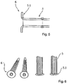
- Figures 5 and 6 show an embodiment according to the invention of the axial lock 6 of the shaft 5.
- this axial lock is provided in one piece with the shaft 5.
- the axial lock has been produced from the shaft 5 by forming it.
- the axial securing is preferably a so-called flattened area 5.1, ie in this area the shaft 5, which has been designed here as a tube, is set up here by 90°.
- This embodiment of the present invention has the advantage that it is very space-saving and weight-minimizing.
- this embodiment is very easy to assemble, because there is no need to machine the shaft, at least on one side, after it has been assembled.
Landscapes
- Engineering & Computer Science (AREA)
- Aviation & Aerospace Engineering (AREA)
- Transportation (AREA)
- Mechanical Engineering (AREA)
- Seats For Vehicles (AREA)
- Chairs For Special Purposes, Such As Reclining Chairs (AREA)
Description
- Die vorliegende Erfindung betrifft einen Fahrzeugsitz mit einem Rückenlehnenteil, das mittels eines Lehnenverstellers drehbar an einem Sitzteil vorgesehen ist, wobei der Lehnenversteller eine Welle aufweist, die vorzugsweise ein Drehmoment auf den Lehnenversteller überträgt.
An Fahrzeugsitze werden heutzutage sehr hohe Sicherungsanforderungen gestellt. Beispielsweise muss sichergestellt sein, dass bei einem Heckaufprall der Fahrzeugsitz die auftretenden Lasten aufnehmen kann.US6357828B1 offenbart einen gattungsgemässen Fahrzeugsitz. - Es war deshalb die Aufgabe der vorliegenden Erfindung einen derartigen Fahrzeugsitz zur Verfügung zu stellen.
- Gelöst wird die Aufgabe mit einem Fahrzeugsitz nach Anspruch 1.
- Der erfindungsgemäße Fahrzeugsitz hat den Vorteil, dass die bei einem Heckaufprall entstehenden Kräfte in Y-Richtung, d. h. quer zur Fahrtrichtung, die Lastaufnahmefähigkeit des Fahrzeugsitzes, insbesondere des Lehnenverstellers, nicht überschreiten.
Die vorliegende Erfindung betrifft einen Fahrzeugsitz, der aus einem Rückenlehnenteil und einem Sitzteil besteht. Ein derartiger Fahrzeugsitz kann einer oder mehreren Personen Platz bieten. Bei dem erfindungsgemäßen Fahrzeugsitz kann es sich auch um eine Sitzbank handeln.
Die Rückenlehne ist mittels eines Lehnenverstellers drehbar an dem Sitzteil vorgesehen beispielsweise um zu Komfortzwecken die Neigung der Rückenlehne verstellen zu können. Derartige Lehnenversteller sind rechts und links an dem erfindungsgemäßen Fahrzeugsitz vorgesehen. Erfindungsgemäß weist der Fahrzeugsitz eine Welle auf, die ein Drehmoment auf mindestens einen der beiden Lehnenversteller zur Änderung der Winkelstellung der Rückenlehne überträgt. - Erfindungsgemäss ist die Welle rohrförmig ausgestaltet. Vorzugsweise weist die Welle an ihrem Umfang Form- und/oder Kraftschlussmittel auf, um ein Drehmoment auf den Lehnenversteller übertragen zu können. Diese Welle ist nun an beiden Enden mit einer Axialsicherung versehen, mit der verhindert wird, dass sich die Welle beispielsweise bei einem Heckaufprall aus dem jeweiligen Lehnenversteller herauszieht, wodurch zum einen die Stabilität des Lehnenverstellers aber auch insgesamt die Stabilität des Fahrzeugsitzes gefährdet wäre. Vorzugsweise sind die Axialsicherungen an den beiden Enden der Welle gleich, ganz besonders bevorzugt jedoch unterschiedlich.
- Bei einer nicht zur Erfindung gehörenden Ausführung handelt es sich bei der Axialsicherung um ein mit der Welle stoffschlüssig verbundenes Mittel insbesondere eine Scheibe. Der Stoffschluss kann durch Kleben, insbesondere jedoch durch Schweißen erfolgen.
- Weiterhin kann bei einer nicht zur Erfindung gehörenden Ausführung die Axialsicherung als ein Starlock-Washer ausgeführt sein, wobei dieser mit einem Werkzeug auf die Welle aufgeschoben und an der jeweiligen Stelle positioniert wird.
- Weiterhin kann bei einer nicht zur Erfindung gehörenden Ausführung die Axialsicherung als eine gewindeschneidende Mutter ausgeführt sein.
- Erfindungsgemäss ist die Axialsicherung einstückig mit der Welle vorgesehen, vorzugsweise durch Umformen aus dieser hergestellt. Insbesondere ist die Axialsicherung ein geflarter Bereich. Beim Flaren wird das Ende der Welle, die vorzugsweise rohrförmig vorgesehen ist, manuell oder maschinell um einen bestimmten Winkel, vorzugsweise um 80° - 100°, insbesondere 90°, aufgestellt. Dies erfolgt vorzugsweise mit einem Press- oder Taumelprozess. Diese bevorzugte Ausführungsform der vorliegenden Erfindung hat den Vorteil, dass sie eine sehr hohe Belastbarkeit >5 kN aufweist. Der Flareprozess ist sehr kostengünstig. Darüber hinaus weist eine geflarte Welle einen ausgesprochen geringen Bauraum auf.
- Im Folgenden wird die Erfindung anhand der
Figuren 1 ,2 ,5 und 6 erläutert. Diese Erläuterungen sind lediglich beispielhaft und schränken den allgemeinen Erfindungsgedanken nicht ein. -
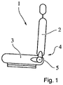
Figur 1 zeigt den erfindungsgemäßen Fahrzeugsitz. -
Figur 2 zeigt den Sitzversteller mit der Welle. -
Figuren 3 bis 6 zeigen Ausführungsformen der Axialsicherung der Welle. -
Figur 3 zeigt eine erste, nicht zur Erfindung gehörende Ausführungsform einer solchen Axialsicherung. In diesem Fall handelt es sich um eine Scheibe, die auf die Welle 5 aufgeschweißt worden ist. -
Figuren 4a - c zeigen eine weitere, nicht zur Erfindung gehörende Ausführungsform der Axialsicherung, die in dem vorliegenden Fall ein sogenannter Starlock-Washer ist. Dieser Starlock-Washer wird mit einem Werkzeug auf die Welle 5 aufgeschoben und an die jeweils gewünschte Position verschoben. -
Figuren 5 und 6 zeigen eine erfindungsgemässe Ausführungsform der Axialsicherung 6 der Welle 5. In dem vorliegenden Fall ist diese Axialsicherung einstückig mit der Welle 5 vorgesehen. Die Axialsicherung ist durch Umformen aus der Welle 5 hergestellt worden. Bei der Axialsicheung handelt es sich vorzugsweise um einen sogenannten geflarten Bereich 5.1, d.h. in diesem Bereich ist die Welle 5, die hier als Rohr ausgeführt worden ist, um hier 90° aufgestellt. Diese Ausführungsform der vorliegenden Erfindung hat den Vorteil, dass sie sehr platzsparend und gewichtsminimierend ist. Darüber hinaus ist diese Ausführungsform sehr leicht zu montieren, weil auf eine Bearbeitung der Welle, nachdem sie montiert worden ist, zumindest einseitig verzichtet werden kann. -
- 1
- Fahrzeugsitz
- 2
- Rückenlehne
- 3
- Sitzteil
- 4
- Lehnenversteller, Recliner
- 5
- Welle, Achse
- 5.1
- getuplter Abschnitt, gekelchter Abschnitt, umgelegter Abschnitt, geflarter Abschnitt
- 6
- Axialsicherung
Claims (3)
- Fahrzeugsitz (1) mit einem Rückenlehnenteil (2), das mittels eines Lehnenverstellers (4) drehbar an einem Sitzteil (3) vorgesehen ist, wobei der Lehnenversteller (4) eine Welle (5) aufweist, die vorzugsweise ein Drehmoment auf den Lehnenversteller (4) überträgt, wobei an der Welle (5) an beiden Enden eine Axialsicherung (6) vorgesehen ist, dadurch gekennzeichnet, dass die Welle (5) als ein Rohr ausgebildet ist, wobei die Axialsicherung (6) einstückig mit der Welle (5) vorgesehen ist und ein geflarter Bereich der Welle (5) ist.
- Fahrzeugsitz nach Anspruch 1, dadurch gekennzeichnet, dass die Axialsicherung (6) durch ein Ziehen des Endes der Welle (5) um einen definierten Winkel geformt worden ist.
- Fahrzeugsitz nach Anspruch 1, dadurch gekennzeichnet, dass die Axialsicherungen gleich oder unterschiedlich sind.
Applications Claiming Priority (3)
| Application Number | Priority Date | Filing Date | Title |
|---|---|---|---|
| DE102010044947A DE102010044947A1 (de) | 2010-09-10 | 2010-09-10 | Fahrzeugsitz mit einer axial gesicherten Welle |
| PCT/EP2011/004533 WO2012031764A1 (de) | 2010-09-10 | 2011-09-08 | Fahrzeugsitz mit einer axial gesicherten welle |
| EP11761003.0A EP2613964B1 (de) | 2010-09-10 | 2011-09-08 | Fahrzeugsitz mit einer axial gesicherten welle |
Related Parent Applications (1)
| Application Number | Title | Priority Date | Filing Date |
|---|---|---|---|
| EP11761003.0A Division EP2613964B1 (de) | 2010-09-10 | 2011-09-08 | Fahrzeugsitz mit einer axial gesicherten welle |
Publications (3)
| Publication Number | Publication Date |
|---|---|
| EP2913221A1 EP2913221A1 (de) | 2015-09-02 |
| EP2913221B1 EP2913221B1 (de) | 2018-11-14 |
| EP2913221B2 true EP2913221B2 (de) | 2022-09-28 |
Family
ID=44677836
Family Applications (2)
| Application Number | Title | Priority Date | Filing Date |
|---|---|---|---|
| EP15160561.5A Active EP2913221B2 (de) | 2010-09-10 | 2011-09-08 | Fahrzeugsitz mit einer axial gesicherten welle |
| EP11761003.0A Active EP2613964B1 (de) | 2010-09-10 | 2011-09-08 | Fahrzeugsitz mit einer axial gesicherten welle |
Family Applications After (1)
| Application Number | Title | Priority Date | Filing Date |
|---|---|---|---|
| EP11761003.0A Active EP2613964B1 (de) | 2010-09-10 | 2011-09-08 | Fahrzeugsitz mit einer axial gesicherten welle |
Country Status (7)
| Country | Link |
|---|---|
| US (1) | US9446688B2 (de) |
| EP (2) | EP2913221B2 (de) |
| JP (1) | JP5642284B2 (de) |
| KR (1) | KR101432225B1 (de) |
| CN (1) | CN103108772B (de) |
| DE (1) | DE102010044947A1 (de) |
| WO (1) | WO2012031764A1 (de) |
Families Citing this family (2)
| Publication number | Priority date | Publication date | Assignee | Title |
|---|---|---|---|---|
| JP2014227026A (ja) * | 2013-05-22 | 2014-12-08 | ナミテイ株式会社 | 駆動シャフト及びこの駆動シャフトを有する電動シート |
| DE102016201483B4 (de) * | 2015-10-28 | 2023-05-04 | Keiper Seating Mechanisms Co., Ltd. | Beschlagsystem für einen Fahrzeugsitz, sowie Fahrzeugsitz |
Citations (3)
| Publication number | Priority date | Publication date | Assignee | Title |
|---|---|---|---|---|
| DE19724554A1 (de) † | 1997-06-11 | 1998-12-24 | Faure Bertrand Sitztech Gmbh | Kraftfahrzeugsitz mit neigungsverstellbarer Rückenlehne |
| DE10352630A1 (de) † | 2003-11-11 | 2005-06-30 | Faurecia Autositze Gmbh & Co. Kg | Kraftfahrzeugsitz mit neigungsverstellbarer Rückenlehne |
| US20100219319A1 (en) † | 2009-02-20 | 2010-09-02 | Faurecia Sieges D'automobile | Vehicle Seat, Manufacturing Process for Such a Vehicle Seat, and Machine for Implementing the Manufacturing Process |
Family Cites Families (25)
| Publication number | Priority date | Publication date | Assignee | Title |
|---|---|---|---|---|
| US1122040A (en) * | 1914-04-17 | 1914-12-22 | George W Springsteen | Folding back for saddles. |
| US2969705A (en) * | 1956-03-22 | 1961-01-31 | United Carr Fastener Corp | Self-threading sheet metal nut |
| US2986059A (en) * | 1957-11-18 | 1961-05-30 | Palnut Company | Self threading sheet metal nut |
| US3395602A (en) * | 1965-07-05 | 1968-08-06 | Tinnerman Products Inc | Self-threading nut |
| US3426386A (en) * | 1967-01-05 | 1969-02-11 | Vernon Duke | Locking device for pivoted members |
| US3501995A (en) * | 1968-12-02 | 1970-03-24 | Illinois Tool Works | Thread-cutting nut |
| US3557655A (en) * | 1969-07-03 | 1971-01-26 | Keystone Consolidated Ind Inc | Extruded thread-cutting nut |
| US4448381A (en) * | 1980-01-14 | 1984-05-15 | International Telephone And Telegraph Corporation | Motor mount structure for vehicle seat adjustment apparatus |
| US4865385A (en) * | 1988-07-07 | 1989-09-12 | Hiroshi Suzuki | Reclining device for bucket seat |
| JP2672360B2 (ja) * | 1989-01-23 | 1997-11-05 | シロキ工業株式会社 | 両側リクライニング装置の連動機構 |
| JPH04111915U (ja) | 1991-03-19 | 1992-09-29 | カヤバ工業株式会社 | ローラ取付装置 |
| JP3653818B2 (ja) * | 1995-09-22 | 2005-06-02 | アイシン精機株式会社 | 駆動装置 |
| JP2000027102A (ja) | 1998-07-10 | 2000-01-25 | Kmf:Kk | レール締結ショルダー固定装置 |
| JP3578925B2 (ja) * | 1998-11-30 | 2004-10-20 | 富士機工株式会社 | シートリクライニング装置における振動音防止構造 |
| DE19921810B4 (de) * | 1999-05-11 | 2004-11-18 | Keiper Gmbh & Co. Kg | Rastbeschlag für einen Fahrzeugsitz |
| DE10008204C2 (de) | 2000-02-23 | 2002-06-27 | Faurecia Autositze Gmbh & Co | Bauteilverbindung zwischen zwei Bauteilen eines Kraftfahrzeugsitzes |
| DE10037190C2 (de) * | 2000-07-31 | 2003-09-25 | Faurecia Autositze Gmbh & Co | Kraftfahrzeugsitz mit neigungseinstellbarer Rückenlehne |
| JP4670134B2 (ja) | 2000-09-28 | 2011-04-13 | アイシン精機株式会社 | シートリクライニング装置 |
| CN2732537Y (zh) | 2004-10-10 | 2005-10-12 | 江苏省溧阳市汽车座椅调角器总厂 | 内藏式双齿板汽车座椅调角器 |
| CN101252856B (zh) * | 2005-08-30 | 2012-04-04 | 丰田纺织株式会社 | 座椅倾斜装置 |
| US7513573B2 (en) | 2006-09-12 | 2009-04-07 | Lear Corporation | Continuous recliner |
| JP5055926B2 (ja) | 2006-09-29 | 2012-10-24 | アイシン精機株式会社 | 車両用シート装置 |
| US7703852B2 (en) | 2007-12-03 | 2010-04-27 | Lear Corporation | Heavy duty reclining mechanism for vehicle seats |
| JP2009299824A (ja) | 2008-06-16 | 2009-12-24 | Hochiki Corp | 銘板取付構造 |
| EP2347929B1 (de) | 2008-10-20 | 2016-04-13 | NHK Spring Co., Ltd. | Sitzlehnenrahmenstruktur eines Sitzes für Fahrzeug und Sitz für Fahrzeug mit Sitzlehnenrahmenstruktur |
-
2010
- 2010-09-10 DE DE102010044947A patent/DE102010044947A1/de active Pending
-
2011
- 2011-09-08 EP EP15160561.5A patent/EP2913221B2/de active Active
- 2011-09-08 WO PCT/EP2011/004533 patent/WO2012031764A1/de not_active Ceased
- 2011-09-08 US US13/820,062 patent/US9446688B2/en active Active
- 2011-09-08 CN CN201180043383.5A patent/CN103108772B/zh active Active
- 2011-09-08 JP JP2013527495A patent/JP5642284B2/ja not_active Expired - Fee Related
- 2011-09-08 EP EP11761003.0A patent/EP2613964B1/de active Active
- 2011-09-08 KR KR1020137008773A patent/KR101432225B1/ko not_active Expired - Fee Related
Patent Citations (3)
| Publication number | Priority date | Publication date | Assignee | Title |
|---|---|---|---|---|
| DE19724554A1 (de) † | 1997-06-11 | 1998-12-24 | Faure Bertrand Sitztech Gmbh | Kraftfahrzeugsitz mit neigungsverstellbarer Rückenlehne |
| DE10352630A1 (de) † | 2003-11-11 | 2005-06-30 | Faurecia Autositze Gmbh & Co. Kg | Kraftfahrzeugsitz mit neigungsverstellbarer Rückenlehne |
| US20100219319A1 (en) † | 2009-02-20 | 2010-09-02 | Faurecia Sieges D'automobile | Vehicle Seat, Manufacturing Process for Such a Vehicle Seat, and Machine for Implementing the Manufacturing Process |
Also Published As
| Publication number | Publication date |
|---|---|
| EP2613964B1 (de) | 2015-03-25 |
| CN103108772B (zh) | 2017-03-01 |
| DE102010044947A1 (de) | 2012-03-15 |
| EP2913221B1 (de) | 2018-11-14 |
| JP5642284B2 (ja) | 2014-12-17 |
| WO2012031764A1 (de) | 2012-03-15 |
| CN103108772A (zh) | 2013-05-15 |
| JP2013537128A (ja) | 2013-09-30 |
| KR20130052682A (ko) | 2013-05-22 |
| EP2613964A1 (de) | 2013-07-17 |
| US20130221721A1 (en) | 2013-08-29 |
| KR101432225B1 (ko) | 2014-08-26 |
| EP2913221A1 (de) | 2015-09-02 |
| US9446688B2 (en) | 2016-09-20 |
Similar Documents
| Publication | Publication Date | Title |
|---|---|---|
| DE112010005253B4 (de) | Verstellvorrichtung mit einem an einer Führungsschiene angeordneten Verstellgetriebe und Verfahren zur Montage einer Verstellvorrichtung | |
| EP2736764B1 (de) | Sitzgestell eines kraftfahrzeugsitzes mit zwei seitenteilen und einem querrohr | |
| EP1970260B1 (de) | Crashbox und Kraftfahrzeug-Stoßfängeranordnung | |
| DE102014202086B3 (de) | Höheneinsteller für einen Fahrzeugsitz und Fahrzeugsitz | |
| EP2125423B1 (de) | Sitzversteller, insbesondere rückenlehnenneigungsversteller | |
| EP2450224A1 (de) | Getriebebaueinheit einer Verstelleinrichtung eines Kraftfahrzeugs | |
| DE102014208852C5 (de) | Doppelbeschlag für einen Fahrzeugsitz und Fahrzeugsitz | |
| EP4334168A1 (de) | Höhenverstelleinrichtung eines fahrzeugsitzes | |
| DE102010005471A1 (de) | Beschlagsystem für einen Fahrzeugsitz | |
| EP1513717B1 (de) | Sicherheitsvorrichtung zum arretieren eines verstellbaren anschlussteils | |
| EP2913221B2 (de) | Fahrzeugsitz mit einer axial gesicherten welle | |
| DE112012004351B4 (de) | Sitz mit verschweißter Querwelle | |
| DE102006033990A1 (de) | Kraftfahrzeug mit einer Längs- und Querträger aufweisenden Tragstruktur | |
| DE102012107036B4 (de) | Kraftfahrzeugsitz | |
| EP4100279A1 (de) | Längseinsteller und fahrzeugsitz | |
| EP2993076B1 (de) | Beschlag und fahrzeugsitz | |
| DE102009022935A1 (de) | Vorrichtung zum gezielten Verformen von Längsträgern von Kraftfahrzeugen | |
| DE102004027550B4 (de) | Lehnenmittellager | |
| DE102014220131B4 (de) | Verstellvorrichtung und Fahrzeugsitz mit Verstellvorrichtung | |
| DE10053048B4 (de) | Fahrzeugsitz | |
| WO2023104756A1 (de) | Baugruppe eines fahrzeugs mit einer eine verbindungsbaugruppe aufweisenden führungsschiene | |
| DE102016212514A1 (de) | Beschlagteil für einen Beschlag eines Fahrzeugsitzes, Beschlag für einen Fahrzeugsitz und Fahrzeugsitz | |
| WO2024208703A1 (de) | Aus zumindest zwei komponenten zusammengesetzter quertraeger fuer ein fahrzeug | |
| EP4051530A1 (de) | Beschlag für einen fahrzeugsitz | |
| WO2007118547A1 (de) | Kraftfahrzeugsitz mit einem recliner |
Legal Events
| Date | Code | Title | Description |
|---|---|---|---|
| PUAI | Public reference made under article 153(3) epc to a published international application that has entered the european phase |
Free format text: ORIGINAL CODE: 0009012 |
|
| AC | Divisional application: reference to earlier application |
Ref document number: 2613964 Country of ref document: EP Kind code of ref document: P |
|
| AK | Designated contracting states |
Kind code of ref document: A1 Designated state(s): AL AT BE BG CH CY CZ DE DK EE ES FI FR GB GR HR HU IE IS IT LI LT LU LV MC MK MT NL NO PL PT RO RS SE SI SK SM TR |
|
| 17P | Request for examination filed |
Effective date: 20160302 |
|
| RBV | Designated contracting states (corrected) |
Designated state(s): AL AT BE BG CH CY CZ DE DK EE ES FI FR GB GR HR HU IE IS IT LI LT LU LV MC MK MT NL NO PL PT RO RS SE SI SK SM TR |
|
| RAP1 | Party data changed (applicant data changed or rights of an application transferred) |
Owner name: ADIENT LUXEMBOURG HOLDING S.A R.L. |
|
| RAP1 | Party data changed (applicant data changed or rights of an application transferred) |
Owner name: ADIENT LUXEMBOURG HOLDING S.A R.L. |
|
| GRAP | Despatch of communication of intention to grant a patent |
Free format text: ORIGINAL CODE: EPIDOSNIGR1 |
|
| STAA | Information on the status of an ep patent application or granted ep patent |
Free format text: STATUS: GRANT OF PATENT IS INTENDED |
|
| INTG | Intention to grant announced |
Effective date: 20180619 |
|
| GRAS | Grant fee paid |
Free format text: ORIGINAL CODE: EPIDOSNIGR3 |
|
| GRAA | (expected) grant |
Free format text: ORIGINAL CODE: 0009210 |
|
| STAA | Information on the status of an ep patent application or granted ep patent |
Free format text: STATUS: THE PATENT HAS BEEN GRANTED |
|
| AC | Divisional application: reference to earlier application |
Ref document number: 2613964 Country of ref document: EP Kind code of ref document: P |
|
| AK | Designated contracting states |
Kind code of ref document: B1 Designated state(s): AL AT BE BG CH CY CZ DE DK EE ES FI FR GB GR HR HU IE IS IT LI LT LU LV MC MK MT NL NO PL PT RO RS SE SI SK SM TR |
|
| REG | Reference to a national code |
Ref country code: CH Ref legal event code: EP Ref country code: AT Ref legal event code: REF Ref document number: 1064399 Country of ref document: AT Kind code of ref document: T Effective date: 20181115 |
|
| REG | Reference to a national code |
Ref country code: DE Ref legal event code: R096 Ref document number: 502011015018 Country of ref document: DE |
|
| REG | Reference to a national code |
Ref country code: IE Ref legal event code: FG4D Free format text: LANGUAGE OF EP DOCUMENT: GERMAN |
|
| REG | Reference to a national code |
Ref country code: NL Ref legal event code: MP Effective date: 20181114 |
|
| REG | Reference to a national code |
Ref country code: LT Ref legal event code: MG4D |
|
| PG25 | Lapsed in a contracting state [announced via postgrant information from national office to epo] |
Ref country code: ES Free format text: LAPSE BECAUSE OF FAILURE TO SUBMIT A TRANSLATION OF THE DESCRIPTION OR TO PAY THE FEE WITHIN THE PRESCRIBED TIME-LIMIT Effective date: 20181114 Ref country code: IS Free format text: LAPSE BECAUSE OF FAILURE TO SUBMIT A TRANSLATION OF THE DESCRIPTION OR TO PAY THE FEE WITHIN THE PRESCRIBED TIME-LIMIT Effective date: 20190314 Ref country code: NO Free format text: LAPSE BECAUSE OF FAILURE TO SUBMIT A TRANSLATION OF THE DESCRIPTION OR TO PAY THE FEE WITHIN THE PRESCRIBED TIME-LIMIT Effective date: 20190214 Ref country code: HR Free format text: LAPSE BECAUSE OF FAILURE TO SUBMIT A TRANSLATION OF THE DESCRIPTION OR TO PAY THE FEE WITHIN THE PRESCRIBED TIME-LIMIT Effective date: 20181114 Ref country code: BG Free format text: LAPSE BECAUSE OF FAILURE TO SUBMIT A TRANSLATION OF THE DESCRIPTION OR TO PAY THE FEE WITHIN THE PRESCRIBED TIME-LIMIT Effective date: 20190214 Ref country code: LT Free format text: LAPSE BECAUSE OF FAILURE TO SUBMIT A TRANSLATION OF THE DESCRIPTION OR TO PAY THE FEE WITHIN THE PRESCRIBED TIME-LIMIT Effective date: 20181114 Ref country code: FI Free format text: LAPSE BECAUSE OF FAILURE TO SUBMIT A TRANSLATION OF THE DESCRIPTION OR TO PAY THE FEE WITHIN THE PRESCRIBED TIME-LIMIT Effective date: 20181114 Ref country code: LV Free format text: LAPSE BECAUSE OF FAILURE TO SUBMIT A TRANSLATION OF THE DESCRIPTION OR TO PAY THE FEE WITHIN THE PRESCRIBED TIME-LIMIT Effective date: 20181114 |
|
| PG25 | Lapsed in a contracting state [announced via postgrant information from national office to epo] |
Ref country code: AL Free format text: LAPSE BECAUSE OF FAILURE TO SUBMIT A TRANSLATION OF THE DESCRIPTION OR TO PAY THE FEE WITHIN THE PRESCRIBED TIME-LIMIT Effective date: 20181114 Ref country code: SE Free format text: LAPSE BECAUSE OF FAILURE TO SUBMIT A TRANSLATION OF THE DESCRIPTION OR TO PAY THE FEE WITHIN THE PRESCRIBED TIME-LIMIT Effective date: 20181114 Ref country code: RS Free format text: LAPSE BECAUSE OF FAILURE TO SUBMIT A TRANSLATION OF THE DESCRIPTION OR TO PAY THE FEE WITHIN THE PRESCRIBED TIME-LIMIT Effective date: 20181114 Ref country code: NL Free format text: LAPSE BECAUSE OF FAILURE TO SUBMIT A TRANSLATION OF THE DESCRIPTION OR TO PAY THE FEE WITHIN THE PRESCRIBED TIME-LIMIT Effective date: 20181114 Ref country code: PT Free format text: LAPSE BECAUSE OF FAILURE TO SUBMIT A TRANSLATION OF THE DESCRIPTION OR TO PAY THE FEE WITHIN THE PRESCRIBED TIME-LIMIT Effective date: 20190314 Ref country code: GR Free format text: LAPSE BECAUSE OF FAILURE TO SUBMIT A TRANSLATION OF THE DESCRIPTION OR TO PAY THE FEE WITHIN THE PRESCRIBED TIME-LIMIT Effective date: 20190215 |
|
| PG25 | Lapsed in a contracting state [announced via postgrant information from national office to epo] |
Ref country code: CZ Free format text: LAPSE BECAUSE OF FAILURE TO SUBMIT A TRANSLATION OF THE DESCRIPTION OR TO PAY THE FEE WITHIN THE PRESCRIBED TIME-LIMIT Effective date: 20181114 Ref country code: PL Free format text: LAPSE BECAUSE OF FAILURE TO SUBMIT A TRANSLATION OF THE DESCRIPTION OR TO PAY THE FEE WITHIN THE PRESCRIBED TIME-LIMIT Effective date: 20181114 Ref country code: DK Free format text: LAPSE BECAUSE OF FAILURE TO SUBMIT A TRANSLATION OF THE DESCRIPTION OR TO PAY THE FEE WITHIN THE PRESCRIBED TIME-LIMIT Effective date: 20181114 Ref country code: IT Free format text: LAPSE BECAUSE OF FAILURE TO SUBMIT A TRANSLATION OF THE DESCRIPTION OR TO PAY THE FEE WITHIN THE PRESCRIBED TIME-LIMIT Effective date: 20181114 |
|
| REG | Reference to a national code |
Ref country code: DE Ref legal event code: R026 Ref document number: 502011015018 Country of ref document: DE |
|
| PLBI | Opposition filed |
Free format text: ORIGINAL CODE: 0009260 |
|
| PG25 | Lapsed in a contracting state [announced via postgrant information from national office to epo] |
Ref country code: SM Free format text: LAPSE BECAUSE OF FAILURE TO SUBMIT A TRANSLATION OF THE DESCRIPTION OR TO PAY THE FEE WITHIN THE PRESCRIBED TIME-LIMIT Effective date: 20181114 Ref country code: EE Free format text: LAPSE BECAUSE OF FAILURE TO SUBMIT A TRANSLATION OF THE DESCRIPTION OR TO PAY THE FEE WITHIN THE PRESCRIBED TIME-LIMIT Effective date: 20181114 Ref country code: RO Free format text: LAPSE BECAUSE OF FAILURE TO SUBMIT A TRANSLATION OF THE DESCRIPTION OR TO PAY THE FEE WITHIN THE PRESCRIBED TIME-LIMIT Effective date: 20181114 Ref country code: SK Free format text: LAPSE BECAUSE OF FAILURE TO SUBMIT A TRANSLATION OF THE DESCRIPTION OR TO PAY THE FEE WITHIN THE PRESCRIBED TIME-LIMIT Effective date: 20181114 |
|
| PLAX | Notice of opposition and request to file observation + time limit sent |
Free format text: ORIGINAL CODE: EPIDOSNOBS2 |
|
| 26 | Opposition filed |
Opponent name: BROSE FAHRZEUGTEILE GMBH & CO. KG, COBURG Effective date: 20190813 |
|
| PG25 | Lapsed in a contracting state [announced via postgrant information from national office to epo] |
Ref country code: SI Free format text: LAPSE BECAUSE OF FAILURE TO SUBMIT A TRANSLATION OF THE DESCRIPTION OR TO PAY THE FEE WITHIN THE PRESCRIBED TIME-LIMIT Effective date: 20181114 |
|
| PLBB | Reply of patent proprietor to notice(s) of opposition received |
Free format text: ORIGINAL CODE: EPIDOSNOBS3 |
|
| PG25 | Lapsed in a contracting state [announced via postgrant information from national office to epo] |
Ref country code: TR Free format text: LAPSE BECAUSE OF FAILURE TO SUBMIT A TRANSLATION OF THE DESCRIPTION OR TO PAY THE FEE WITHIN THE PRESCRIBED TIME-LIMIT Effective date: 20181114 |
|
| PG25 | Lapsed in a contracting state [announced via postgrant information from national office to epo] |
Ref country code: MC Free format text: LAPSE BECAUSE OF FAILURE TO SUBMIT A TRANSLATION OF THE DESCRIPTION OR TO PAY THE FEE WITHIN THE PRESCRIBED TIME-LIMIT Effective date: 20181114 |
|
| REG | Reference to a national code |
Ref country code: CH Ref legal event code: PL |
|
| PG25 | Lapsed in a contracting state [announced via postgrant information from national office to epo] |
Ref country code: LI Free format text: LAPSE BECAUSE OF NON-PAYMENT OF DUE FEES Effective date: 20190930 Ref country code: IE Free format text: LAPSE BECAUSE OF NON-PAYMENT OF DUE FEES Effective date: 20190908 Ref country code: CH Free format text: LAPSE BECAUSE OF NON-PAYMENT OF DUE FEES Effective date: 20190930 Ref country code: LU Free format text: LAPSE BECAUSE OF NON-PAYMENT OF DUE FEES Effective date: 20190908 |
|
| REG | Reference to a national code |
Ref country code: BE Ref legal event code: MM Effective date: 20190930 |
|
| PG25 | Lapsed in a contracting state [announced via postgrant information from national office to epo] |
Ref country code: BE Free format text: LAPSE BECAUSE OF NON-PAYMENT OF DUE FEES Effective date: 20190930 |
|
| GBPC | Gb: european patent ceased through non-payment of renewal fee |
Effective date: 20190908 |
|
| PG25 | Lapsed in a contracting state [announced via postgrant information from national office to epo] |
Ref country code: GB Free format text: LAPSE BECAUSE OF NON-PAYMENT OF DUE FEES Effective date: 20190908 |
|
| REG | Reference to a national code |
Ref country code: AT Ref legal event code: MM01 Ref document number: 1064399 Country of ref document: AT Kind code of ref document: T Effective date: 20190908 |
|
| PG25 | Lapsed in a contracting state [announced via postgrant information from national office to epo] |
Ref country code: AT Free format text: LAPSE BECAUSE OF NON-PAYMENT OF DUE FEES Effective date: 20190908 |
|
| PG25 | Lapsed in a contracting state [announced via postgrant information from national office to epo] |
Ref country code: CY Free format text: LAPSE BECAUSE OF FAILURE TO SUBMIT A TRANSLATION OF THE DESCRIPTION OR TO PAY THE FEE WITHIN THE PRESCRIBED TIME-LIMIT Effective date: 20181114 |
|
| REG | Reference to a national code |
Ref country code: DE Ref legal event code: R082 Ref document number: 502011015018 Country of ref document: DE Representative=s name: KUTZENBERGER WOLFF & PARTNER PATENTANWALTSPART, DE Ref country code: DE Ref legal event code: R082 Ref document number: 502011015018 Country of ref document: DE Representative=s name: LIEDTKE & PARTNER PATENTANWAELTE, DE Ref country code: DE Ref legal event code: R081 Ref document number: 502011015018 Country of ref document: DE Owner name: KEIPER SEATING MECHANISMS CO., LTD., CN Free format text: FORMER OWNER: ADIENT LUXEMBOURG HOLDING S.A R.L., LUXEMBOURG, LU Ref country code: DE Ref legal event code: R081 Ref document number: 502011015018 Country of ref document: DE Owner name: KEIPER SEATING MECHANISMS CO., LTD., CN Free format text: FORMER OWNER: ADIENT YANFENG SEATING MECHANISM CO., LTD, SHANGHAI, CN |
|
| PG25 | Lapsed in a contracting state [announced via postgrant information from national office to epo] |
Ref country code: HU Free format text: LAPSE BECAUSE OF FAILURE TO SUBMIT A TRANSLATION OF THE DESCRIPTION OR TO PAY THE FEE WITHIN THE PRESCRIBED TIME-LIMIT; INVALID AB INITIO Effective date: 20110908 Ref country code: MT Free format text: LAPSE BECAUSE OF FAILURE TO SUBMIT A TRANSLATION OF THE DESCRIPTION OR TO PAY THE FEE WITHIN THE PRESCRIBED TIME-LIMIT Effective date: 20181114 |
|
| PG25 | Lapsed in a contracting state [announced via postgrant information from national office to epo] |
Ref country code: MK Free format text: LAPSE BECAUSE OF FAILURE TO SUBMIT A TRANSLATION OF THE DESCRIPTION OR TO PAY THE FEE WITHIN THE PRESCRIBED TIME-LIMIT Effective date: 20181114 |
|
| PUAH | Patent maintained in amended form |
Free format text: ORIGINAL CODE: 0009272 |
|
| STAA | Information on the status of an ep patent application or granted ep patent |
Free format text: STATUS: PATENT MAINTAINED AS AMENDED |
|
| 27A | Patent maintained in amended form |
Effective date: 20220928 |
|
| AK | Designated contracting states |
Kind code of ref document: B2 Designated state(s): AL AT BE BG CH CY CZ DE DK EE ES FI FR GB GR HR HU IE IS IT LI LT LU LV MC MK MT NL NO PL PT RO RS SE SI SK SM TR |
|
| REG | Reference to a national code |
Ref country code: DE Ref legal event code: R102 Ref document number: 502011015018 Country of ref document: DE |
|
| REG | Reference to a national code |
Ref country code: DE Ref legal event code: R082 Ref document number: 502011015018 Country of ref document: DE Representative=s name: KUTZENBERGER WOLFF & PARTNER PATENTANWALTSPART, DE |
|
| PGFP | Annual fee paid to national office [announced via postgrant information from national office to epo] |
Ref country code: DE Payment date: 20250702 Year of fee payment: 15 |
|
| PGFP | Annual fee paid to national office [announced via postgrant information from national office to epo] |
Ref country code: FR Payment date: 20250703 Year of fee payment: 15 |