EP2913009B1 - Retraktor - Google Patents
Retraktor Download PDFInfo
- Publication number
- EP2913009B1 EP2913009B1 EP15163758.4A EP15163758A EP2913009B1 EP 2913009 B1 EP2913009 B1 EP 2913009B1 EP 15163758 A EP15163758 A EP 15163758A EP 2913009 B1 EP2913009 B1 EP 2913009B1
- Authority
- EP
- European Patent Office
- Prior art keywords
- retractor
- surgical
- light source
- component
- neck
- Prior art date
- Legal status (The legal status is an assumption and is not a legal conclusion. Google has not performed a legal analysis and makes no representation as to the accuracy of the status listed.)
- Active
Links
Images




Classifications
-
- A—HUMAN NECESSITIES
- A61—MEDICAL OR VETERINARY SCIENCE; HYGIENE
- A61B—DIAGNOSIS; SURGERY; IDENTIFICATION
- A61B1/00—Instruments for performing medical examinations of the interior of cavities or tubes of the body by visual or photographical inspection, e.g. endoscopes; Illuminating arrangements therefor
- A61B1/32—Devices for opening or enlarging the visual field, e.g. of a tube of the body
-
- A—HUMAN NECESSITIES
- A61—MEDICAL OR VETERINARY SCIENCE; HYGIENE
- A61B—DIAGNOSIS; SURGERY; IDENTIFICATION
- A61B17/00—Surgical instruments, devices or methods
- A61B17/02—Surgical instruments, devices or methods for holding wounds open, e.g. retractors; Tractors
- A61B17/0218—Surgical instruments, devices or methods for holding wounds open, e.g. retractors; Tractors for minimally invasive surgery
-
- A—HUMAN NECESSITIES
- A61—MEDICAL OR VETERINARY SCIENCE; HYGIENE
- A61B—DIAGNOSIS; SURGERY; IDENTIFICATION
- A61B90/00—Instruments, implements or accessories specially adapted for surgery or diagnosis and not covered by any of the groups A61B1/00 - A61B50/00, e.g. for luxation treatment or for protecting wound edges
- A61B90/30—Devices for illuminating a surgical field, the devices having an interrelation with other surgical devices or with a surgical procedure
-
- A—HUMAN NECESSITIES
- A61—MEDICAL OR VETERINARY SCIENCE; HYGIENE
- A61B—DIAGNOSIS; SURGERY; IDENTIFICATION
- A61B90/00—Instruments, implements or accessories specially adapted for surgery or diagnosis and not covered by any of the groups A61B1/00 - A61B50/00, e.g. for luxation treatment or for protecting wound edges
- A61B90/30—Devices for illuminating a surgical field, the devices having an interrelation with other surgical devices or with a surgical procedure
- A61B90/35—Supports therefor
-
- A—HUMAN NECESSITIES
- A61—MEDICAL OR VETERINARY SCIENCE; HYGIENE
- A61B—DIAGNOSIS; SURGERY; IDENTIFICATION
- A61B90/00—Instruments, implements or accessories specially adapted for surgery or diagnosis and not covered by any of the groups A61B1/00 - A61B50/00, e.g. for luxation treatment or for protecting wound edges
- A61B90/36—Image-producing devices or illumination devices not otherwise provided for
-
- A—HUMAN NECESSITIES
- A61—MEDICAL OR VETERINARY SCIENCE; HYGIENE
- A61B—DIAGNOSIS; SURGERY; IDENTIFICATION
- A61B90/00—Instruments, implements or accessories specially adapted for surgery or diagnosis and not covered by any of the groups A61B1/00 - A61B50/00, e.g. for luxation treatment or for protecting wound edges
- A61B90/36—Image-producing devices or illumination devices not otherwise provided for
- A61B90/361—Image-producing devices, e.g. surgical cameras
-
- A—HUMAN NECESSITIES
- A61—MEDICAL OR VETERINARY SCIENCE; HYGIENE
- A61B—DIAGNOSIS; SURGERY; IDENTIFICATION
- A61B90/00—Instruments, implements or accessories specially adapted for surgery or diagnosis and not covered by any of the groups A61B1/00 - A61B50/00, e.g. for luxation treatment or for protecting wound edges
- A61B90/50—Supports for surgical instruments, e.g. articulated arms
-
- A—HUMAN NECESSITIES
- A61—MEDICAL OR VETERINARY SCIENCE; HYGIENE
- A61B—DIAGNOSIS; SURGERY; IDENTIFICATION
- A61B17/00—Surgical instruments, devices or methods
- A61B17/02—Surgical instruments, devices or methods for holding wounds open, e.g. retractors; Tractors
- A61B17/0281—Abdominal wall lifters
-
- A—HUMAN NECESSITIES
- A61—MEDICAL OR VETERINARY SCIENCE; HYGIENE
- A61B—DIAGNOSIS; SURGERY; IDENTIFICATION
- A61B17/00—Surgical instruments, devices or methods
- A61B2017/00017—Electrical control of surgical instruments
-
- A—HUMAN NECESSITIES
- A61—MEDICAL OR VETERINARY SCIENCE; HYGIENE
- A61B—DIAGNOSIS; SURGERY; IDENTIFICATION
- A61B17/00—Surgical instruments, devices or methods
- A61B17/02—Surgical instruments, devices or methods for holding wounds open, e.g. retractors; Tractors
- A61B2017/0237—Surgical instruments, devices or methods for holding wounds open, e.g. retractors; Tractors for heart surgery
-
- A—HUMAN NECESSITIES
- A61—MEDICAL OR VETERINARY SCIENCE; HYGIENE
- A61B—DIAGNOSIS; SURGERY; IDENTIFICATION
- A61B90/00—Instruments, implements or accessories specially adapted for surgery or diagnosis and not covered by any of the groups A61B1/00 - A61B50/00, e.g. for luxation treatment or for protecting wound edges
- A61B90/30—Devices for illuminating a surgical field, the devices having an interrelation with other surgical devices or with a surgical procedure
- A61B2090/306—Devices for illuminating a surgical field, the devices having an interrelation with other surgical devices or with a surgical procedure using optical fibres
-
- A—HUMAN NECESSITIES
- A61—MEDICAL OR VETERINARY SCIENCE; HYGIENE
- A61B—DIAGNOSIS; SURGERY; IDENTIFICATION
- A61B90/00—Instruments, implements or accessories specially adapted for surgery or diagnosis and not covered by any of the groups A61B1/00 - A61B50/00, e.g. for luxation treatment or for protecting wound edges
- A61B90/30—Devices for illuminating a surgical field, the devices having an interrelation with other surgical devices or with a surgical procedure
- A61B2090/309—Devices for illuminating a surgical field, the devices having an interrelation with other surgical devices or with a surgical procedure using white LEDs
-
- A—HUMAN NECESSITIES
- A61—MEDICAL OR VETERINARY SCIENCE; HYGIENE
- A61B—DIAGNOSIS; SURGERY; IDENTIFICATION
- A61B90/00—Instruments, implements or accessories specially adapted for surgery or diagnosis and not covered by any of the groups A61B1/00 - A61B50/00, e.g. for luxation treatment or for protecting wound edges
- A61B90/36—Image-producing devices or illumination devices not otherwise provided for
- A61B90/37—Surgical systems with images on a monitor during operation
- A61B2090/372—Details of monitor hardware
Definitions
- the present invention relates to surgical instruments, especially to a device for facilitating minimally invasive cardiovascular or thoracic surgery.
- the invention relates to a device for expanding the thoracic basket to within its natural limits of expansion, directionally illuminating the chest cavity and providing surgical instrumentation to the surgical field.
- thoracic surgery including cardiovascular surgery
- the operation necessitates the surgical division of the patient's sternum, such that the thoracic basket, or rib cage, can be prised apart.
- the division of the rib cage allows the surgeon access to the patient's thoracic cavity.
- the patient's sternum is split by the use of a chest saw, and the two halves held apart using a retractor.
- the manubrium supports the clavicles, and the peripheries of the manubrium and body support the first seven pairs of ribs.
- Heat loss from wet surfaces is significant from open sternal wounds.
- Chest incisions made through splitting the sternum only heal as fast as the fracture in the breastbone can heal. It typically takes several months for the bone to unite fully.
- the division of the chest can also lead to patients suffering from neurological disorders following open chest surgery, such as numbness in the hands.
- Heat loss from wet surfaces is much less from a small neck incision than an extensive open sternal wound.
- Blood loss will be minimal through a small neck incision in comparison to open sternal incisions. Because no bone is divided and bone marrow is not exposed.
- Neck incisions heal more quickly than conventional open-chest incisions. This is because they are smaller and the skin and soft tissues of the neck have a much better blood supply than those over the chest. The latter also reduces potential infections.
- the present invention obviates or mitigates the foregoing deficiencies of the prior art devices and methods.
- a retractor instrument for use in a minimally invasive cardiovascular or thoracic surgical procedure forms the subject matter of claim 1.
- Various embodiments are the subject matter of the dependent claims..
- the disclosed retractor blade incorporates a plurality of lights, which are independently controllable, and arranged to provide illumination to selected zones, e.g. to facilitate procedures within the surgical field.
- the light configuration may be selectively operated according to (a) a predetermined sequence programme, or (b) a sequence determined by a user of the retractor, in order to provide illumination at the most suitable place at any appropriate stage of the procedure.
- the retractor may be provided with switches, or connected to a microprocessor for controlling and actuating a pre-determined timed sequence of light operation.
- a disposable medical instrument and light pipe assembly is disclosed in US 4 562 832 .
- the instrument may be a retractor of the abdominal type or speculum for parting tissue.
- the light pipe assembly has bendable light director neck parts which in the course of an open surgical procedure can be manually bent by a surgeon to re-direct light on a particular region of a surgical site.
- the instrument When the instrument is a retractor it has a rectangular form blade with rounded corners, and apertures for receiving soft tissue to inhibit slippage or displacement of the blade.
- a standard non-disposable retractor may be used within a slot of a strip of resilient plastic material adapted to contact tissue in a surgical site, and that the slotted strip has a keyhole for receiving a part of a light pipe in a snap fit.
- Known illuminated retractors may generate glare through reflection of light from body tissues at some stage of the procedure e.g. during insertion of the instrument, and any such impediment to the vision of a surgeon as user of the instrument causes delay in the procedure and increases risk to the patient undergoing the procedure.
- Known retractors equipped with lighting may be designed to deliver light only in one direction, whereas in fact it is desirable to view more than one anatomical structure during a procedure, and an instrument of the known type generally cannot appropriately achieve this objective.
- suitable light sources include LEDs, and use of optical fibres in conjunction with an appropriate light source, the latter permitting any external light source to be adopted with use of suitable optics in the instrument to direct the light as required.
- halogen or xenon light sources can be adopted. In some instances, such sources are preferable due to the ability to reduce and intensify the light output at will using known dimmer technology.
- optical fibre bundles can be used to bring light directly into an intracorporeal operating field from suitably positioned light ports in the retractor.
- LEDs offer known advantages as light sources, such as negligible heat output, small size and light weight, which enables them to be locally mounted upon the retractor and thereby directly within the intracorporeal operating field, and also offer directed light in a generally narrow beam spread. Thus these are efficient enough to selectively direct sufficient light using a portable power source, e.g. button cells, or batteries concealed within the instrument.
- a portable power source e.g. button cells, or batteries concealed within the instrument.
- Avoidance of undue glare or stray light may be achieved by appropriate switching of lights, or use of anti-glare shielding in appropriate positions e.g. behind a light source from the point of view of a user.
- Switching of the light sources can be manually controlled using switches upon the instrument, or controlled according to a predetermined timed sequence, e.g. using a microprocessor. Alternatively light output control is achievable by use of shuttering devices.
- the direction and or breadth of light cast by the lighting devices may be controlled by use of prisms or lenses at the light ports.
- Combinations of different lighting devices are contemplated to provide widespread lighting as in a floodlight, or localised lighting as in a spotlight, as may be required by the surgeon at a particular stage of the surgical procedure.
- Optical components required for the lighting devices may be concealed or recessed within the retractor body parts, or may be mounted upon or project from the retractor body parts.
- a retractor instrument contemplated for the purposes of this invention may be of generally hook or L-shaped configuration, wherein a first component is attachable to a hoist or lifting frame, and a second component which is generally referred to as a blade, projects therefrom to provide a surface adapted to contact a part of the body and move it in response to a lifting force being applied to said first component.
- Such a retractor may comprise a first component configured for hand grip by a user so as to facilitate manipulation by a user, and a second component configured as a blade for insertion through an incision.
- the first component adapted as a hand grip, also can be usefully employed to house stored power units, controllers for light sources, optics components, etc.
- the second component configured as a blade part, can be usefully employed to carry a viewing device.
- the viewing device may be mounted upon a swivel or ball.
- the viewing device can be in the nature of a telescope, a camera or an imaging device to transfer real time images to an external monitor.
- a retractor instrument may be configured to support and introduce imaging or viewing devices to the surgical field.
- Fibre optics are useful in this respect in conjunction with cameras, prisms, lens devices or telescopes.
- CCD charge coupled
- CMOS complementary metal-oxide-semiconductor
- the blade is formed from a tubular frame and the space between a pair of opposed limbs of the frame can be utilised to house devices such as reusable camera modules.
- a cover plate over the frame provides strength to the blade to support weight and also to distribute loadings across the frame. The need to spread the load in the same way that a normal blade does arises from the fact that were only a frame structure to be introduced to the thoracic cavity, the limbs would contact costal cartilages on either side of the sternum. Costal cartilages are much weaker than bone, and at risk of breakage with resultant painful injury to the patient.
- a push- or snap-fit clip may be used to attach such a camera module or the like device to the tubular elements of the blade.
- the camera module may be mounted upon a ball or swivel housed within a two piece housing that defines a socket therebetween.
- the two piece housing may have front and rear portions formed to cooperate by an interference fit to form a socket mounting.
- the said portions are conveniently formed in plastics and fastened together by a staking technique, preferably by heat staking.
- the portions may have shape-retaining flexible side elements including curved parts adapted to conform to a tubular frame element and serve as respective push-fit clamp elements allowing re-positioning along the tubular frame element at will.
- a ball member is disposed in the socket and depending upon the design of the housing portions, may be centred or offset.
- Locking means to hold the ball in a predetermined position may be provided.
- Such locking means may be mechanical (e.g. a set or "grub” screw) or electromagnetic (e.g. a solenoid).
- the camera may be intended for intracorporeal use and is preferably removable for cleaning if it is of a reusable type, or for disposal if of the disposable type.
- the camera may be integral with the retractor, and adapted for reuse as a whole unit, or the whole unit may be disposable.
- the camera may be an extracorporeal camera to be used in conjunction with a telescope integrated with or adapted to fit within the retractor.
- the retractor may comprise a first elongate component having at one end means for attachment or engagement with a lifting device and at the other end there is a second elongate component projecting therefrom at an angle in the range of 30 to 120 degrees, to facilitate lifting of a body part.
- the components may be adjustably connected to permit a user to actuate and determine a suitable internal angle between the first elongate component and the second elongate component.
- a retractor instrument as disclosed herein is of a generally hook or L-shaped configuration, and comprises a first component that is removably attachable to a novel lifting frame that includes an arm extending from an upstanding pivotal mounting whereby in use in association with an operating table, the arm may be moved from an overhanging position over the operating table to a position to one side of the operating table.
- An advantage of this lifting frame design is that in the event that a complication arises during the surgical procedure, the retractor can be released and the frame can be quickly moved to facilitate access by operating theatre staff to allow emergency procedures or the like interventions to be conducted swiftly.
- hoists in association with operating tables are not unknown in operating theatres, they normally comprise an operating table-fixed frame or "bridge-frame" consisting of a pair of opposed upright supports and a crossbar upon which lifting tackle is carried.
- the supports are normally clamped to the operating table, and require disassembly and removal by operating department assistants (ODAs) who have to be summoned to the operating theatre to remove the known type of bridge frame.
- ODAs operating department assistants
- pivotal support arm e.g. mounted upon a single upright support post
- a pivotal support arm offers numerous advantages in terms of ease of access, and saving of time which can prove critical to the well-being of a patient who develops complications during a surgical procedure.
- the support post may be ground-supported by insertion into a floor socket for the purpose, or into a weighted base unit, or preferably mounted upon one of the long edges of the operating table.
- the support post provides a pivotal mounting for the overhanging support arm in one embodiment by provision of a free-running bearing within its assembled length, preferably a thrust bearing.
- the support post for the pivotally mounted lifting arm is attached by a frame that passes under the operating table and is fastened in a manner spreading the load across the underside of the operating table.
- the fastening means for the under table frame may comprise quick-release clamps.
- the under table frame may comprise a plurality of struts connecting between clamps for fastening the frame to the operating table.
- a three-point connection offers some advantages in use with respect to stability of the upright support post, and consequential fixing of the overhanging arm in a stable position over the operating table.
- Clamps may be adjustable on threaded members with engaging parts adapted to fit onto rails, or into channels provided on the longitudinal sides of the operating table, or optionally adapted to fit around or under longitudinal edges thereof.
- the upright support post may be fastenable to the surgical table by a frame assembly (14) including a plurality of connected load-bearing frame members (52) configured to pass underneath the surgical table and be fastened at both longitudinal sides thereof and also be connected to the upright support post (18).
- a frame assembly (14) including a plurality of connected load-bearing frame members (52) configured to pass underneath the surgical table and be fastened at both longitudinal sides thereof and also be connected to the upright support post (18).
- the load-bearing struts may form a three point linked framework, wherein the upright support post is positioned at an apex of the framework and is connected by frame members to at least first and second fastening joints (51) arranged transversely with respect to the surgical table.
- the fastening joints may include clamps that are adjustably fastenable to the surgical table to allow re-location or removal of the framework.
- An advantage of mounting the frame from underneath the operating table is that there is a clear unobstructed path for surgical instruments to be passed between an instrument table and the surgeon.
- the support post may incorporate within its length a mechanical or electromechanical actuator such as a threaded rod movable within the support to serve as a "screw-jack" to elevate the arm without any discernible change in the angle of its overhang over the operating table. This is desirable to avoid changing the orientation or position of the retractor or other instrument supported with the arm when inserted into a body part which could be harmful to the patient undergoing the surgical procedure.
- a mechanical or electromechanical actuator such as a threaded rod movable within the support to serve as a "screw-jack” to elevate the arm without any discernible change in the angle of its overhang over the operating table.
- the jack may be operated by means of a hand crank, or hydraulically, or by means of electromotive power.
- the jack incorporates a safety retention device to avoid slippage of the jack from a desired setting, i.e. to prevent the jack from lowering under load, especially to avoid drop-back after lifting of a patient.
- a mechanical system for converting rotational motion into linear motion may comprise a crank operatively associated with bevel gears mounted upon a rotatable shaft connected to or forming part of the screw jack, the gears being concealed within a shroud cover to prevent cross-contamination between gear lubricant and the external sterile field.
- Other gearing arrangements are possible e.g. worm gears.
- a hand crank with appropriate gearing may be preferred by some users due to the "hands-on" direct control perception derived from use of same. Minor adjustments may be achievable more easily with such a simple device in the hands of a skilled operator. Others may prefer to use a control system using electric motors or servo motors to smoothly elevate the arm by an appropriate amount within predetermined limits. In the case of an electric motor or hydraulic system, the controlling mechanism (a push button, say) can be kept within the sterile field.
- the pivotally mounted arm has a free end adapted to receive a retractor or other surgical tool.
- the retractor or tool may be cradled in a suitably configured end part of the arm.
- a retractor may be adapted to be suspended from the arm by provision of opposed pins adapted to seat in corresponding recesses in a cradle, whereby the retractor is free to pivot to allow forward and reverse motion for the blade of the retractor.
- the arm may incorporate a swivel mounting to support the retractor directly or the cradle from which it depends in order to allow additional freedom of movement laterally in respect of turning capability during manipulation of the retractor by a user.
- the first and second components of the retractor are disposed at an angle of from 30 to 120 degrees.
- the said angle is selected by the user to provide a user-actuated functional angle.
- the retractor may be configured to be reversibly but securely coupled with the posterior of the sternum of a patient undergoing a surgical procedure.
- the retractor may be configured to be reversibly but securely coupled with the interior face of the patient's sternum.
- the retractor is configured to be reversibly but securely connected to pulling means in the nature of a hoist, crane or winch adapted to permit controlled lifting of a body part.
- the retractor is configured to include channels through which instrumentation can be passed and affixed.
- the retractor may be configured to introduce or provide tools or instruments for use in surgical manipulation.
- the retractor may be adapted to draw or cut sutures.
- the second component is configured to be inserted beneath the suprasternal notch of the sternum of a substantially supine patient.
- the second component is configured to be inserted beneath the Xiphoid process of the sternum of a substantially supine patient.
- the second component is configured to be inserted into the body of a substantially supine patient to facilitate access to the interior of said body by a surgeon.
- the said second component is configured to reversibly but securely couple with the underside of the sternum manubrium of a substantially supine patient.
- the first component may be configured to comprise a sprung clip at the distal end.
- the retractor may be configured to confer a substantially vertical pulling force from a lifting device e.g. a winch, to a patient's sternum causing the patient's ribcage to expand optimally.
- a lifting device e.g. a winch
- the retractor is configured to confer a substantially vertical pulling force from the winch to patient's sternum causing the patient's rib cage to expand to its natural limits.
- the retractor comprises surgical instrumentation for use in a procedure to be conducted within a body cavity.
- the said surgical instrumentation includes means for use in suturing.
- the said surgical instrumentation includes a means of grasping sutures.
- the said surgical instrumentation includes a means of grasping tissue.
- the said surgical instrumentation is operable manually by the surgeon.
- the said surgical instrumentation is operable manually by an assistant.
- the said surgical instrumentation is operable by an automated system.
- the retractor is adapted to illuminate a body cavity by provision of at least two light sources, specifically, a first light source to provide widespread illumination to illuminate a body cavity within which a procedure is to be carried out, and at least one directed light source to permit a user to have a particular part within the cavity illuminated to facilitate the procedure.
- a first light source to provide widespread illumination to illuminate a body cavity within which a procedure is to be carried out
- at least one directed light source to permit a user to have a particular part within the cavity illuminated to facilitate the procedure.
- the retractor comprises a fibre optic cable system connected to a low or substantially zero heat output light source, to illuminate the intended operative field within a body cavity, which is adapted to be inserted through a cannula to facilitate viewing of the operative field.
- the low or substantially zero heat light source may be a halogen or xenon light source.
- filters are employed with the light source to reduce the transmission of excessive heat to the operating site.
- the low or substantially zero heat light produced is substantially the same or similar in electromagnetic spectrum to natural light.
- the retractor comprises at least one telescopic lens connected to a video camera for observing the interior of a body cavity.
- the said body cavity is the thoracic cavity, and the retractor is configured for insertion therein.
- the retractor comprises an adaptor for receiving electrical power.
- the retractor comprises a stored electrical power source.
- the retractor may comprise at least first and second components adjustably connected to include an angle of from 30° to 120°, and at least one of said components comprises a housing having an upper light occlusive part, and a lower light transmissive part, said housing incorporating internal mounting means for at least first light source, and external mounting means for a further light source, and the other component being adapted to be releasably attached to a lifting device.
- the retractor includes a means to connect to an external power source when an alternative energy source is needed.
- Said first and second sections may be permanently connected at a predetermined angle in respect of one another.
- the angle at which said first section is connected to said second section is adjustable.
- a retractor comprises mutually spaced tubular elements paired to form an upstanding component of the retractor, wherein upper ends of the tubular elements engage with a cradle adapted for pendular mounting of the retractor upon an arm of a support frame, and at the end of the tubular elements remote from the cradle, curved tubular elements form a "heel" portion of the retractor, and further mutually spaced tubular elements extend laterally therefrom at an inclined angle to form the basis for a blade component of the retractor, and a cover plate overlies these inclined tubular elements to form a load distribution surface for contacting a body part, and a toe cap piece forms the tip of the blade component of the retractor, and wherein a first lighting device is positioned in a downwardly directed light port within a tubular part at the heel portion of the retractor, a second lighting device is positioned within a forwardly directed light port in ahead of the heel portion, and a third lighting device is positioned in a downwardly directed light port in
- One or more or the said lighting devices may be spotlights to provide localised lighting when required, and one or more may provide a wider beam of light in the manner of a floodlight to illuminate a larger field.
- the first and second lighting devices are designed to serve as spotlights, and the third is designed to act as a floodlight.
- the blade portion of the retractor may comprise spaced tubular parts and a viewing device may be mounted in a removable pod comprising a two-part plastics housing within which a ball mounting is captive, said housing having shape-retaining flexible wing elements for removably attaching the housing to the tubular parts by press-fitting between the spaced tubular parts, and the ball has a throughbore to allow insertion of the viewing device.
- the viewing device may be movable with respect to the blade portion.
- the viewing device may comprise an optical fibre bundle cable coupled to a camera or other image capture device whereby the viewed operating field can be transferred to an image display or storage device.
- a minimally invasive procedure such as chest surgery to replace a heart valve, comprises the steps of providing a retractor of the type disclosed herein and as discussed above
- the invention as referred to in its various aspects hereinbefore is intended for use in an operating theatre where space around an operating table is limited in view of the persons in attendance and the associated equipment required to support the patient.
- a plan view of an operating table 16 with floorspace "footprints" occupied by medical staff and apparatus is shown in Figure 1 .
- surgeon 1 who intends to conduct the operational procedure stands at head of the operating table 16 to provide best position for access to the patient for the purposes of an aortic valve replacement procedure.
- the assistant surgeon 2 stands to the left of the surgeon 1.
- An anaesthetic machine 3 that is required to provide an accurate and continuous supply of medical gases (such as oxygen and nitrous oxide), mixed with an accurate concentration of anaesthetic vapour (such as isoflurane), for delivery to the patient at a safe pressure and flow is adjacent the head of the operating table, between the assistant surgeon 2 and the anaesthetist 4.
- Such a machine 3 may incorporate a ventilator, suction unit, and patient-monitoring devices.
- a perfusionist 5 operates a cardiopulmonary bypass machine 6 positioned to the side of the operating table 16.
- a circulating nurse 7 ("runner") at the outset is stationed at the foot of the operating table 16.
- the instrument table 8 is located to one side at the foot of the operating table 16, and attended by one or more scrub nurses 9 .
- a patient lies upon an operating table 16.
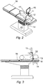
- Apparatus for supporting the surgical procedure includes a retractor 11 that is held above the patient by a lifting frame 12 with a pivotal arm 17 which overhangs the operating table 16 in an operational position, and that arm in turn is height-adjustably supported upon an upright support post 18 provided with a manually cranked winch 13.
- the support post is fixed to the operating table by means of a mounting frame 14 that is adapted to engage side rails on the operating table by clamps (not shown) that are adjustable upon threaded members to lock and secure the apparatus in position, but which allow its removal when required.
- An advantage of having a pivotal support arm is that if a complication develops during the procedure, it is possible to quickly swing the support arm away from above the patient, enabling the surgeon to move to the right of the operating table and revert to an emergent open sternum approach.
- the mounting frame 14 approximates to a right angled triangle when viewed in plan, and comprises a plurality of struts 52 ( Figure 5a ), linking connecting posts 51 at apexes of the triangular configuration.
- These posts 51 may incorporate the adjustable clamps, and one of these posts also serves as the primary mounting for the support post 18 that conceals within it a lifting jack 54 forming part of the winch 13 that is operated by hand crank 55 through bevel gear system 56 upon thrust bearing 57.
- a monitor 15 is also adjustably supported upon the arm 17 so as to be readily within the surgeon's field of view. This is especially advantageous to thereby allow the surgeon to view the procedure without shifting body position by turning to the side for example which would have the critical drawback of consequentially causing the loss of precise control of surgical instruments in the operating field.
- a parallel linkage enables the monitor to be lowered in front of the retractor to allow the surgeon to look down upon the displayed image, which allows alignment of the visual with the motor axes of the operator. Use of such a parallel linkage allows the monitor to be moved (translated in a plane) without altering the viewing angle.
- the retractor 11 comprises mutually spaced tubular elements 25 paired to form an upstanding component of the retractor 11.
- the upper ends of the tubular elements engage with a cradle 24 forming the principal means of suspending the retractor from the end of arm 17.
- Fibre optic bundles 22 are passed through the cradle 24 into the tubular elements 25, and light cable connectors 23 are operatively connected to the fibre optic bundles and located in housing 29 seated in the cradle 24.
- tubular elements At the lower end of the tubular elements 25, curved tubular elements form a "heel" portion of the retractor 11, and further mutually spaced tubular elements extend laterally therefrom at an inclined angle to form the basis for a blade component of the retractor.
- a cover plate 26 is applied over these inclined tubular elements to form a load distribution surface for contacting a body part.
- a "toe" cap piece 27 forms the leading edge of the blade component of the retractor 11.
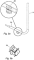
- the removable pod consists of a plastics housing in two parts forming a front part 94 and a rear part 95 configured to define therebetween a socket within which a ball or swivel is captive when assembled.
- the two piece housing front and rear portions are formed to receive deformable pins 92 to lock them together e.g. by use of a heat staking method.
- the portions may have shape-retaining flexible wing elements 91 including curved parts adapted to conform with a tubular frame element and serve as respective push-fit clamp elements.
- a ball member 93 is captive in the socket such that it can pivot and swivel and has a central throughbore for receiving a viewing or imaging device, such as a camera or telescope.
- a camera 84 and camera cable 82 are fixed to the pod 28 with considerable freedom of movements under the retractor blade by virtue of the ball mount in the pod 28.
- the pod 28 is also slidable along the tubular elements making up the retractor blade.
- the cone representation in these figures illustrates the field of view available to the surgeon in use of the device.
- FIG. 7a - 7d an embodiment of the unique lighting system is illustrated.
- Discretely controllable lighting is positioned within light ports 71 , 72 , and 73 .
- the cone representations in Figures 7a - 7c depict a field of illumination available selectively by appropriate switching means (not shown).
- a retractor of this type is shown in an operative position depending from lifting frame 12 (depicted in isolation from the operating table) at the end of overhanging arm 17 in Figures 5a and 5b .
- Housing 29 is provided with pivot pins 64 that seat in corresponding recesses in the cradle 24.
- Light cables 63 are connected to the connectors 23 and tidied against the arm 17 of lifting frame 12 by cable holder 65.
- AVR Trans cervical aortic valve replacement
- the retractor is configured to comprise a telescope connected to a video camera for observing the interior of the patient's thoracic cavity.
- Said telescope may be positioned by the surgeon, and the video camera is able to project pictures to a screen in the operating theatre. The surgeon is able to observe and magnify the area of interest within the patient's thoracic cavity.
- the telescopic video camera is equipped with a low or non-heat light source, such as an LED.
- the light is directed together with the video camera to illuminate the area observed by the video camera.
- the telescopic camera is configured to be manually aimed by the user in an appropriate direction.
- the telescopic video camera and lighting of the previous embodiment is configured to be directed or guided by the user in an appropriate direction using a signal from a remote control module.
- the means of communicating a signal between said remote control module and said telescopic camera is a means of wireless communication, such as radio frequency (RF) communication, microwave communication, or infrared (IR) short-range communication.
- RF radio frequency
- Suitable radio control systems include pulse width modulation (PWM), pulse position modulation (PPM) and spread spectrum technology, which will actuate the various control surfaces within the structure of the retractor and telescopic camera using servomechanisms.
- the RF device includes a microchip comprising an integrated circuit for storing and processing information, modulating and demodulating a (RF) signal, and an antenna. Power for the device is both from a stored charge device such as a button cell, coin cell or battery, and mains electricity.
- a videoscopic camera that is positioned on the sternal portion of the retractor is controllable by voice activated positioning.
- a videoscopic camera which is positioned on the sternal portion of the retractor is controllable by a system comprising a sensor placed on the surgeon's head configured to track the surgeon's head positioning.
- the telescopic camera and lighting of the previous embodiment is guided by a hard wired remote control mechanism.
- a fibre optic is utilised in lieu of or together with the adjustable light source of the previous embodiment.
- the fibre optic is able to relay the image of the interior of the patient's thoracic cavity to a camera outside of the cavity. The images are then fed through a conventional digital image processor and relayed onto monitors in the theatre.
Landscapes
- Health & Medical Sciences (AREA)
- Life Sciences & Earth Sciences (AREA)
- Surgery (AREA)
- General Health & Medical Sciences (AREA)
- Veterinary Medicine (AREA)
- Biomedical Technology (AREA)
- Heart & Thoracic Surgery (AREA)
- Medical Informatics (AREA)
- Molecular Biology (AREA)
- Animal Behavior & Ethology (AREA)
- Nuclear Medicine, Radiotherapy & Molecular Imaging (AREA)
- Public Health (AREA)
- Engineering & Computer Science (AREA)
- Pathology (AREA)
- Oral & Maxillofacial Surgery (AREA)
- Physics & Mathematics (AREA)
- Biophysics (AREA)
- Optics & Photonics (AREA)
- Radiology & Medical Imaging (AREA)
- Surgical Instruments (AREA)
Claims (14)
- Ein Retraktor (11), der eine erste Komponente und eine zweite Komponente beinhaltet, wobei sich die zweite Komponente in einem Winkel von der ersten Komponente erstreckt, wobei die zweite Komponente eine Breite aufweist, die einen Klingenabschnitt bildet, und wobei eine Oberfläche eine Vielzahl von Beleuchtungsvorrichtungen (71, 72, 73) beinhaltet; dadurch gekennzeichnet, dass der Retraktor (11) ein Thorax-Brustbein-Retraktor (11) ist, der entfernbar an einem Hebearm (17) angebracht ist, welcher drehbar montiert ist, um einen Operationstisch (16) zu überhängen,
zur Verwendung bei einem minimalinvasiven chirurgischen Eingriff am Thorax, bei dem der Zugang zum Thoraxhohlraum über einen Einschnitt im Hals erfolgt,
wobei die erste Komponente einen Halsabschnitt (25) aufweist, der von dem Klingenabschnitt aufrecht steht, sodass sich der Klingenabschnitt von einem Ende des Halsabschnitts (25) erstreckt und das andere Ende des Halsabschnitts (25) an dem Ende des Hebearms (17) aufgehängt ist,
und der Klingenabschnitt der zweiten Komponente eine erste Oberfläche (26) aufweist, die so konfiguriert ist, dass sie reversibel, aber sicher mit der hinteren Seite des Brustbeins eines Patienten, der einem minimalinvasiven chirurgischen Eingriff am Thorax unterzogen wird, verbunden ist, wobei der Zugang zum Thoraxhohlraum über einen Einschnitt im Hals erfolgt, wobei der Klingenabschnitt eine sich verjüngende Spitze (27) beinhaltet, die das Einführen des Klingenabschnitts durch den Einschnitt im Hals eines Patienten, der dem minimalinvasiven chirurgischen Eingriff am Thorax unterzogen wird, erleichtert, und eine zweite Oberfläche, die die Vielzahl von Beleuchtungsvorrichtungen (71, 72, 73) beinhaltet, wobei die Vielzahl von Beleuchtungsvorrichtungen (71, 72, 73) selektiv und unabhängig steuerbar sind, um ausgewählte Zonen innerhalb eines chirurgischen Felds zu beleuchten. - Retraktor gemäß Anspruch 1, wobei mindestens zwei Lichtquellen bereitgestellt sind.
- Retraktor gemäß Anspruch 1, wobei die Vielzahl von selektiv steuerbaren unabhängigen Beleuchtungsvorrichtungen Folgendes beinhaltet:eine erste nach unten gerichtete Lichtquelle (71), die sich an dem Halsabschnitt befindet;eine zweite nach unten gerichtete Lichtquelle (73), die sich auf der zweiten Oberfläche befindet; undeine dritte nach vorne gerichtete Lichtquelle (72), die sich auf der zweiten Oberfläche befindet.
- Retraktor gemäß Anspruch 1 oder Anspruch 3, wobei die Vielzahl von unabhängigen Beleuchtungsvorrichtungen so konfiguriert ist, dass sie Zonen selektiv innerhalb des chirurgischen Felds gemäß einem vorher festgelegten Sequenzprogramm getrennte Beleuchtung bereitstellt.
- Retraktor gemäß Anspruch 4, wobei im Einsatz die vorher festgelegte Sequenz derart ist, dass die erste Lichtquelle (71), die sich am Hals des Retraktors befindet, betätigbar und nach unten gerichtet ist, um die Mobilisierung von Gewebe am Eingang zu dem Einschnitt zu erleichtern, und anschließend diese erste Lichtquelle ausgeschaltet wird und die zweite Lichtquelle (73), die sich an der Unterseite der Klinge des Retraktors befindet und nach unten gerichtet ist und zur allgemeinen Beleuchtung des Körperhohlraums konfiguriert ist, aktiviert wird und anschließend die dritte Lichtquelle (72), die sich an der Unterseite der Klinge des Retraktors befindet, nach vorne gerichtet und zum Leiten von Licht spezifisch auf ein Zielgewebe konfiguriert ist, betätigt wird.
- Retraktor gemäß einem der vorhergehenden Ansprüche, wobei die Beleuchtungsvorrichtungen aus der Gruppe ausgewählt sind, die aus Vorrichtungen besteht, die als Scheinwerfer und Flutlichter konfiguriert sind.
- Retraktor gemäß Anspruch 6, wobei mindestens eine Beleuchtungsvorrichtung als ein Scheinwerfer konfiguriert ist und mindestens eine Beleuchtungsvorrichtung als ein Flutlicht konfiguriert ist.
- Retraktor gemäß einem der vorhergehenden Ansprüche, wobei eine Beobachtungsvorrichtung auf dem Retraktor unter dessen Klingenabschnitt montiert ist.
- Retraktor gemäß Anspruch 8, wobei die Beobachtungsvorrichtung ein Teleskop, eine Kamera, eine Videokamera oder eine andere Bilderfassungsvorrichtung beinhaltet, wodurch das beobachtete Operationsfeld an eine Bildanzeige- oder -speichervorrichtung übertragen werden kann.
- Retraktor gemäß einem der vorhergehenden Ansprüche, wobei der Retraktor so konfiguriert ist, dass er Kanäle umfasst, durch die Instrumente hindurchgeführt und befestigt werden können.
- Retraktor gemäß einem der Ansprüche 1 bis 10, der einen Adapter zum Aufnehmen elektrischer Energie oder eine gespeicherte elektrische Energiequelle beinhaltet.
- Ein Gerät zur Verwendung in einem mit einem Operationstisch (16) ausgestatteten Operationssaal, das Folgendes beinhaltet:
den Retraktor (11) und den beweglichen Arm (17) gemäß einem der Ansprüche 1-11, eine Hebeeinrichtung (12), die im Einsatz mit dem Operationstisch (16) verbunden ist und zum Anheben eines Brustbeins eines sich einer Operation unterziehenden Individuums auf dem Operationstisch (16) angepasst ist, wobei die Hebeeinrichtung (12) einen aufrecht stehenden Stützpfosten (18) beinhaltet und der bewegliche Arm (17) drehbar auf dem aufrecht stehenden Stützpfosten (18) montiert ist, wodurch der bewegliche Arm (17) um den aufrecht stehenden Stützpfosten (18) geschwenkt werden kann, sodass der bewegliche Arm (17) den Operationstisch (16) in einer Position überhängt und in einer anderen Position der bewegliche Arm (17) weggedreht ist, um Zugang zum Operationstisch (16) zu gewähren. - Gerät gemäß Anspruch 12, wobei die drehbare Lagerung für den überhängenden beweglichen Arm (17) ein Axiallager (57) beinhaltet.
- Gerät gemäß einem der Ansprüche 12 oder 13, wobei ein Monitor (15) so auf dem Arm (17) der Hebeeinrichtung (12) montiert ist, dass er sich in der Nähe des Operationsfeldes einer Person befindet, die an einem Individuum auf dem Operationstisch einen Vorgang ausführt.
Applications Claiming Priority (3)
| Application Number | Priority Date | Filing Date | Title |
|---|---|---|---|
| GBGB0800835.1A GB0800835D0 (en) | 2008-01-17 | 2008-01-17 | Retractor |
| EP09701500.2A EP2242429B1 (de) | 2008-01-17 | 2009-01-15 | Retraktor |
| PCT/GB2009/000097 WO2009090383A2 (en) | 2008-01-17 | 2009-01-15 | Retractor |
Related Parent Applications (2)
| Application Number | Title | Priority Date | Filing Date |
|---|---|---|---|
| EP09701500.2A Division EP2242429B1 (de) | 2008-01-17 | 2009-01-15 | Retraktor |
| EP09701500.2A Division-Into EP2242429B1 (de) | 2008-01-17 | 2009-01-15 | Retraktor |
Publications (3)
| Publication Number | Publication Date |
|---|---|
| EP2913009A2 EP2913009A2 (de) | 2015-09-02 |
| EP2913009A3 EP2913009A3 (de) | 2015-09-09 |
| EP2913009B1 true EP2913009B1 (de) | 2019-06-19 |
Family
ID=39165912
Family Applications (2)
| Application Number | Title | Priority Date | Filing Date |
|---|---|---|---|
| EP15163758.4A Active EP2913009B1 (de) | 2008-01-17 | 2009-01-15 | Retraktor |
| EP09701500.2A Active EP2242429B1 (de) | 2008-01-17 | 2009-01-15 | Retraktor |
Family Applications After (1)
| Application Number | Title | Priority Date | Filing Date |
|---|---|---|---|
| EP09701500.2A Active EP2242429B1 (de) | 2008-01-17 | 2009-01-15 | Retraktor |
Country Status (14)
| Country | Link |
|---|---|
| US (2) | US9232886B2 (de) |
| EP (2) | EP2913009B1 (de) |
| JP (2) | JP5462187B2 (de) |
| KR (1) | KR101637558B1 (de) |
| CN (1) | CN101917913B (de) |
| AU (1) | AU2009204732B2 (de) |
| BR (1) | BRPI0906844B1 (de) |
| CA (1) | CA2712110C (de) |
| ES (1) | ES2736473T3 (de) |
| GB (1) | GB0800835D0 (de) |
| MX (1) | MX2010007802A (de) |
| RU (1) | RU2497460C9 (de) |
| TW (1) | TWI481379B (de) |
| WO (1) | WO2009090383A2 (de) |
Families Citing this family (67)
| Publication number | Priority date | Publication date | Assignee | Title |
|---|---|---|---|---|
| GB0800835D0 (en) | 2008-01-17 | 2008-02-27 | Cardioprec Ltd | Retractor |
| AU2011268433A1 (en) * | 2010-06-14 | 2013-01-10 | Maquet Cardiovascular Llc | Surgical instruments, systems and methods of use |
| GB201015746D0 (en) | 2010-09-21 | 2010-10-27 | Cardioprec Ltd | Optical switch |
| US9757109B2 (en) | 2010-12-10 | 2017-09-12 | Illumix Surgical Canada Inc. | Organic light emitting diode illuminated surgical retractor |
| US9622779B2 (en) | 2011-10-27 | 2017-04-18 | DePuy Synthes Products, Inc. | Method and devices for a sub-splenius / supra-levator scapulae surgical access technique |
| US20130197313A1 (en) * | 2012-01-31 | 2013-08-01 | Shaw P. Wan | Surgical retractor with light |
| CN102525578A (zh) * | 2012-03-06 | 2012-07-04 | 赵璧 | 口腔颌面深部组织led照明拉钩 |
| US9357905B2 (en) | 2012-06-01 | 2016-06-07 | Robert Molnar | Airway device, airway assist device and the method of using same |
| US9642606B2 (en) * | 2012-06-27 | 2017-05-09 | Camplex, Inc. | Surgical visualization system |
| US9629523B2 (en) * | 2012-06-27 | 2017-04-25 | Camplex, Inc. | Binocular viewing assembly for a surgical visualization system |
| KR20140016465A (ko) * | 2012-07-30 | 2014-02-10 | 가톨릭대학교 산학협력단 | 기도관리를 위한 자세유지 장치 |
| KR20140016464A (ko) * | 2012-07-30 | 2014-02-10 | 가톨릭대학교 산학협력단 | 기도관리를 위한 자세유지 장치를 포함하는 환자용 침대 |
| EP2887890A4 (de) | 2012-08-23 | 2016-05-18 | Minimally Invasive Surgical Access Ltd | System für direkten aorta-zugang für aortenklappen-transkatheterverfahren |
| DE102013104300A1 (de) * | 2013-04-26 | 2014-11-13 | Aesculap Ag | Teleskopierbare Retraktorhalterung |
| US20140323811A1 (en) * | 2013-04-30 | 2014-10-30 | Invuity, Inc. | Methods and apparatus for retracting tissue |
| WO2014189969A1 (en) * | 2013-05-21 | 2014-11-27 | Camplex, Inc. | Surgical visualization systems |
| WO2015042460A1 (en) | 2013-09-20 | 2015-03-26 | Camplex, Inc. | Surgical visualization systems and displays |
| US10881286B2 (en) | 2013-09-20 | 2021-01-05 | Camplex, Inc. | Medical apparatus for use with a surgical tubular retractor |
| US11147442B2 (en) | 2014-08-08 | 2021-10-19 | Wm & Dg, Inc. | Medical devices and methods of placement |
| US10722110B2 (en) | 2014-08-08 | 2020-07-28 | Wm & Dg, Inc. | Medical devices and methods of placement |
| US11633093B2 (en) | 2014-08-08 | 2023-04-25 | Wm & Dg, Inc. | Medical devices and methods of placement |
| US9918618B2 (en) * | 2014-08-08 | 2018-03-20 | Wm & Dg, Inc. | Medical devices and methods of placement |
| CN104287796B (zh) * | 2014-11-04 | 2016-11-23 | 王刚 | 一种可照明手术扩张器 |
| WO2016090336A1 (en) * | 2014-12-05 | 2016-06-09 | Camplex, Inc. | Surgical visualization systems and displays |
| US20180014914A1 (en) * | 2015-01-20 | 2018-01-18 | Sreevatsan Raghavan | Self-illuminating cheek retractor |
| US10420538B2 (en) | 2015-02-05 | 2019-09-24 | Obp Medical Corporation | Illuminated surgical retractor |
| US9867602B2 (en) | 2015-02-05 | 2018-01-16 | Obp Medical Corporation | Illuminated surgical retractor |
| HK1250471A1 (zh) | 2015-03-25 | 2018-12-21 | 卡姆普勒克斯公司 | 手术可视化系统和显示器 |
| US10433960B1 (en) | 2015-05-07 | 2019-10-08 | Cardioprecision Limited | Method and system for transcatheter intervention |
| US10881387B2 (en) | 2015-06-03 | 2021-01-05 | Obp Medical Corporation | Retractor |
| US10939899B2 (en) | 2015-06-03 | 2021-03-09 | Obp Medical Corporation | End cap assembly for retractor and other medical devices |
| WO2017091704A1 (en) | 2015-11-25 | 2017-06-01 | Camplex, Inc. | Surgical visualization systems and displays |
| JP6944939B2 (ja) | 2015-12-31 | 2021-10-06 | ストライカー・コーポレイション | 仮想オブジェクトにより規定される患者の標的部位に対して外科手術を行うシステムおよび方法 |
| WO2017151734A1 (en) * | 2016-03-01 | 2017-09-08 | Mirus Llc | Systems and methods for position and orientation tracking of anatomy and surgical instruments |
| CN105769266A (zh) * | 2016-04-16 | 2016-07-20 | 梁爱华 | 一种妇科用牵开器 |
| CN114305313B (zh) * | 2017-03-29 | 2025-07-04 | 波士顿科学国际有限公司 | 用于组织牵开的装置和方法 |
| US10918455B2 (en) | 2017-05-08 | 2021-02-16 | Camplex, Inc. | Variable light source |
| EP3654859A4 (de) | 2017-07-18 | 2020-12-02 | Obp Medical Corporation | Minimal-invasives kontaktloses (mint) verfahren zur entnahme der vena saphena magna (vsm) und venöser hydrodissektor und retraktor zur verwendung während des mint-verfahrens |
| US11051682B2 (en) | 2017-08-31 | 2021-07-06 | Wm & Dg, Inc. | Medical devices with camera and methods of placement |
| US10278572B1 (en) | 2017-10-19 | 2019-05-07 | Obp Medical Corporation | Speculum |
| EP3735184A4 (de) | 2018-01-05 | 2022-02-23 | MITRX, Inc. | Retraktor einer tabaksbeutelnaht und verfahren zur verwendung |
| WO2019152523A1 (en) * | 2018-01-30 | 2019-08-08 | Rebound Therapeutics Corporation | Devices and method for access and visualization for lumbar interbody fusion (lif) |
| US10799229B2 (en) | 2018-02-20 | 2020-10-13 | Obp Medical Corporation | Illuminated medical devices |
| RU2691839C1 (ru) * | 2018-09-10 | 2019-06-18 | Вадим Вадимович Далинин | Способ фиксации сердца при операциях аортокоронарного шунтирования. |
| US12257387B2 (en) | 2018-10-10 | 2025-03-25 | Wm & Dg, Inc. | Medical devices for airway management and methods of placement |
| US10653307B2 (en) | 2018-10-10 | 2020-05-19 | Wm & Dg, Inc. | Medical devices for airway management and methods of placement |
| CN114630629A (zh) * | 2019-06-22 | 2022-06-14 | 泰利福生命科学有限公司 | 骨穿透骨内进入装置 |
| EP3993725A1 (de) | 2019-07-03 | 2022-05-11 | Stryker Corporation | Verfahren zur vermeidung von hindernissen für die chirurgische navigation |
| US12458336B2 (en) | 2019-08-21 | 2025-11-04 | Lsi Solutions, Inc. | Sternal ascender apparatus |
| EP4647033A3 (de) * | 2019-08-21 | 2026-01-21 | LSI Solutions, Inc. | Sternumklettervorrichtung |
| US10959609B1 (en) | 2020-01-31 | 2021-03-30 | Obp Medical Corporation | Illuminated suction device |
| US10966702B1 (en) | 2020-02-25 | 2021-04-06 | Obp Medical Corporation | Illuminated dual-blade retractor |
| KR102572893B1 (ko) * | 2020-09-03 | 2023-08-30 | 고려대학교 산학협력단 | 탈부착 암을 구비하는 다목적 외과용 수술 견인기 |
| US11523846B2 (en) * | 2020-10-09 | 2022-12-13 | Viseon, Inc. | Retractor, distractor, and camera system for cervical procedures |
| US11497394B2 (en) | 2020-10-12 | 2022-11-15 | Wm & Dg, Inc. | Laryngoscope and intubation methods |
| AU2021368523A1 (en) * | 2020-10-28 | 2023-05-18 | Alcon Inc. | Imaging tool to support eye surgery |
| CN112353613A (zh) * | 2020-11-30 | 2021-02-12 | 鲁朝康 | 一种医疗手术观察设备 |
| CN112515717B (zh) * | 2020-12-14 | 2023-10-13 | 中国人民解放军联勤保障部队第九六七医院 | 一种用于腰椎骨折手术用半自动控制型手术拉钩 |
| US11484300B2 (en) | 2021-03-30 | 2022-11-01 | Jgmg Bengochea, Llc | Tubular retractor securement frame |
| CN113693651B (zh) * | 2021-09-06 | 2023-01-31 | 宁德市闽东医院 | 一种适用于脑外科手术的自动牵开系统 |
| CN114699181B (zh) * | 2022-04-14 | 2025-12-23 | 春风化雨(苏州)智能医疗科技有限公司 | 外科手术植入成像方法及成像系统 |
| CN115171499B (zh) * | 2022-08-08 | 2023-07-25 | 桂林市人民医院 | 一种骨科手术室护理教学演示装置 |
| KR20240142082A (ko) * | 2023-03-21 | 2024-09-30 | 주식회사 코렌텍 | 리트랙터 홀더 |
| US12318080B2 (en) | 2023-07-21 | 2025-06-03 | Coopersurgical, Inc. | Illuminated surgical retractor capable of hand-held operation and of being mounted to a fixed frame |
| IT202300024408A1 (it) | 2023-11-17 | 2025-05-17 | Marco Ceccarelli | Dispositivo di monitoraggio di divaricazione chirurgica costale |
| CN118370564B (zh) * | 2024-03-19 | 2024-10-29 | 中国人民解放军总医院第一医学中心 | 一种微创扩张通道下led冷光源系统 |
| CN118236104B (zh) * | 2024-05-27 | 2024-08-13 | 深圳大学总医院 | 一种腹主动脉旁淋巴结清扫的手术拉钩控制装置 |
Family Cites Families (76)
| Publication number | Priority date | Publication date | Assignee | Title |
|---|---|---|---|---|
| GB1510744A (en) | 1975-09-11 | 1978-05-17 | Diehl | Electro-mechanical adjustment means for adjusting an electronic digital indicator |
| USD248870S (en) | 1977-04-18 | 1978-08-08 | Hass Martin A | Dental locator for positioning denture |
| EP0101781B1 (de) | 1982-07-30 | 1986-11-20 | W.C. Heraeus GmbH | Wundhaken für chirurgische Zwecke |
| DE3301890C2 (de) | 1983-01-21 | 1986-04-10 | W.C. Heraeus Gmbh, 6450 Hanau | Wundhaken |
| US4562832A (en) | 1984-01-21 | 1986-01-07 | Wilder Joseph R | Medical instrument and light pipe illumination assembly |
| US4616633A (en) | 1985-03-07 | 1986-10-14 | Commonwealth Of Puerto Rico | Retractor for use in oral and maxillofacial surgery |
| US4702230A (en) | 1986-12-08 | 1987-10-27 | Pilling Co. | Adapter for surgical retractor |
| SU1482675A1 (ru) | 1987-03-27 | 1989-05-30 | Хабаровский государственный медицинский институт | Подъемник дл медицинских операций |
| JPH01159615A (ja) | 1987-12-16 | 1989-06-22 | Nippon Telegr & Teleph Corp <Ntt> | 光切替えスイッチ |
| WO1990001768A1 (en) | 1988-08-05 | 1990-02-22 | Matsushita Electric Industrial Co., Ltd. | Optical head |
| JPH04268528A (ja) | 1991-02-22 | 1992-09-24 | Fujikura Ltd | 光ファイバスイッチ |
| JPH04277423A (ja) | 1991-03-05 | 1992-10-02 | Shigeo Nakagawa | ダイヤルスイッチ |
| US5370134A (en) * | 1991-05-29 | 1994-12-06 | Orgin Medsystems, Inc. | Method and apparatus for body structure manipulation and dissection |
| US5676636A (en) | 1994-07-22 | 1997-10-14 | Origin Medsystems, Inc. | Method for creating a mediastinal working space |
| JPH05273476A (ja) | 1992-03-26 | 1993-10-22 | Fujikura Ltd | 光スイッチ |
| JP3476878B2 (ja) * | 1993-11-15 | 2003-12-10 | オリンパス株式会社 | 手術用マニピュレータ |
| EP0788296B1 (de) | 1994-04-07 | 2005-03-23 | Matsushita Electric Industrial Co., Ltd. | Hochfrequenz-heizeinrichtung |
| JP3657293B2 (ja) | 1994-09-09 | 2005-06-08 | テルモ株式会社 | 腹壁吊り上げ装置 |
| US5544268A (en) | 1994-09-09 | 1996-08-06 | Deacon Research | Display panel with electrically-controlled waveguide-routing |
| US20020058931A1 (en) | 1995-06-27 | 2002-05-16 | Jeffrey R. Parker | Light delivery system and applications thereof |
| US5836311A (en) * | 1995-09-20 | 1998-11-17 | Medtronic, Inc. | Method and apparatus for temporarily immobilizing a local area of tissue |
| US6182664B1 (en) | 1996-02-19 | 2001-02-06 | Edwards Lifesciences Corporation | Minimally invasive cardiac valve surgery procedure |
| CA2198036C (en) * | 1996-02-20 | 2000-12-05 | Charles S. Taylor | Access platform for internal mammary dissection |
| US5967973A (en) | 1996-04-26 | 1999-10-19 | United States Surgical | Surgical retractor and method of surgery |
| DE19629304C2 (de) | 1996-07-20 | 2000-12-14 | Aesculap Ag & Co Kg | Chirurgische Vorrichtung zur mechanischen Erweiterung einer Körperhöhle |
| JPH10108824A (ja) * | 1996-10-08 | 1998-04-28 | Shimadzu Corp | 手術用照明装置 |
| US6106497A (en) | 1997-01-31 | 2000-08-22 | Medical Instrument Development Laboratories | System and method for preventing an air embolism in a surgical procedure |
| FR2758969B1 (fr) | 1997-02-04 | 1999-04-30 | Jean Paul Couetil | Ecarteur sternal ou ecarteur thoracique |
| JPH10277043A (ja) | 1997-04-08 | 1998-10-20 | Okada Izai Kk | リトラクター |
| US6196968B1 (en) | 1997-06-02 | 2001-03-06 | General Surgical Innovations, Inc. | Direct vision subcutaneous tissue retractor and method for use |
| US6033361A (en) | 1997-06-02 | 2000-03-07 | General Surgical Innovations, Inc. | Vascular retractor |
| US6591049B2 (en) * | 1997-07-02 | 2003-07-08 | Lumitex, Inc. | Light delivery systems and applications thereof |
| US7306559B2 (en) * | 1997-07-02 | 2007-12-11 | Lumitex, Inc. | Illuminated surgical retractor |
| JP3056375U (ja) | 1997-10-30 | 1999-02-16 | 八重洲無線株式会社 | ノブの位置ぎめ機構 |
| US6033425A (en) | 1997-11-12 | 2000-03-07 | Genzyme Corporation | Lifting rib retractor |
| US5967971A (en) * | 1998-04-14 | 1999-10-19 | Bolser; Jeffrey William | Surgical instrument |
| JP2000007291A (ja) | 1998-06-17 | 2000-01-11 | Araco Corp | スクリュジャッキ |
| US6355030B1 (en) | 1998-09-25 | 2002-03-12 | Cardiothoracic Systems, Inc. | Instruments and methods employing thermal energy for the repair and replacement of cardiac valves |
| JP2000166930A (ja) | 1998-12-09 | 2000-06-20 | Hama Ika Kogyo Kk | 医療用腹壁吊り上げ器具 |
| JP3425878B2 (ja) | 1999-01-28 | 2003-07-14 | 日本電気株式会社 | 光スイッチ、および該光スイッチを有する光スイッチシステム |
| USD433134S (en) | 1999-05-04 | 2000-10-31 | Isadore Pitesky | Tongue retractor |
| JP3968766B2 (ja) | 1999-07-29 | 2007-08-29 | 富士フイルム株式会社 | 電子機器のダイヤルスイッチ |
| GB0120410D0 (en) * | 2001-08-23 | 2001-10-17 | Hussien Maged | Retractor apparatus |
| US6965710B2 (en) | 2001-09-18 | 2005-11-15 | Hitachi Metals, Ltd. | Optical switch and its production method, and optical path-switching apparatus comprising optical switch |
| SE522697C2 (sv) | 2001-11-14 | 2004-03-02 | Spectracure Ab | Terapi- och diagnossystem med fördelare för distribution av strålning |
| DE60334313D1 (de) | 2002-11-19 | 2010-11-04 | J Donald Hill | System und vorrichtung zum durchführen von minimal invasiver koronarer arterienbypassimplantation |
| US6893394B2 (en) | 2002-12-19 | 2005-05-17 | Ethicon, Inc. | Illuminated and vacuum assisted retractor |
| US8377082B2 (en) | 2003-01-14 | 2013-02-19 | Medtronic, Inc. | Methods and apparatus for making precise incisions in body vessels |
| JP2004305525A (ja) * | 2003-04-09 | 2004-11-04 | Sharp Corp | 内視鏡付き腹壁吊り上げ装置 |
| WO2004104673A1 (ja) | 2003-05-26 | 2004-12-02 | Nidec Sankyo Corporation | 光スイッチ装置 |
| JP2005099678A (ja) | 2003-08-20 | 2005-04-14 | Olympus Corp | 光遮断装置および光スイッチ装置 |
| AU2004303424C1 (en) * | 2003-12-18 | 2009-11-05 | Depuy Spine, Inc. | Surgical retractor systems, illuminated cannulae, and methods of use |
| DE202004000501U1 (de) | 2004-01-08 | 2004-04-08 | Hidde, Gregor | Wundhaken mit Beleuchtung und Lichtleiter |
| EP1614394A3 (de) * | 2004-07-02 | 2006-11-02 | Discus Dental Impressions Inc. | Ständersystem für die Zahnheilkunde |
| DE102004050651A1 (de) * | 2004-08-06 | 2006-03-16 | Carl Zeiss Surgical Gmbh | Beleuchtungseinrichtung sowie Beobachtungseinrichtung |
| JP4508849B2 (ja) | 2004-11-30 | 2010-07-21 | 株式会社ケンウッド | 回転つまみのストッパー構造 |
| US20060217597A1 (en) | 2005-02-18 | 2006-09-28 | Spotlight Surgical, Inc. | Surgical illumination system |
| USD523142S1 (en) | 2005-04-13 | 2006-06-13 | Nemcomed | Orthopaedic retractor |
| USD522140S1 (en) | 2005-04-14 | 2006-05-30 | Nemcomed | Orthopaedic retractor |
| US7346245B2 (en) | 2005-11-16 | 2008-03-18 | National University Corporation, Hamamatsu University School Of Medicine | Switch-type imaging fiber apparatus and branch-type imaging fiber apparatus |
| US8480576B2 (en) | 2005-12-07 | 2013-07-09 | Faheem A. Sandhu | Access system for minimally invasive spinal surgery |
| US8409088B2 (en) | 2006-01-18 | 2013-04-02 | Invuity, Inc. | Retractor illumination system |
| US8876687B2 (en) * | 2006-03-08 | 2014-11-04 | Zimmer Spine, Inc. | Surgical retractor and retractor assembly |
| US7686492B2 (en) * | 2006-06-13 | 2010-03-30 | Invuity, Inc. | Film illumination system |
| USD589145S1 (en) | 2006-07-21 | 2009-03-24 | North American Rescue Products, Inc. | Tracheal retractor hook |
| US7597554B2 (en) | 2006-11-14 | 2009-10-06 | Enrique Fernandez Del Busto Ortega | Device for unilateral or bilateral illumination of oral cavity |
| WO2008072577A1 (ja) | 2006-12-11 | 2008-06-19 | Alps Electric Co., Ltd. | 照光装置及びこれを備えた照光機能付き入力装置 |
| USD568471S1 (en) | 2007-07-06 | 2008-05-06 | Engler Alan M | Implant retractor |
| GB0800835D0 (en) | 2008-01-17 | 2008-02-27 | Cardioprec Ltd | Retractor |
| USD586914S1 (en) | 2008-04-25 | 2009-02-17 | Dasilva Manuel | Surgical retractor |
| US7850171B2 (en) | 2008-10-23 | 2010-12-14 | Igt | Gaming system, device and method involving a plurality of rotors interchangeably operable in a decoupled mode and a coupled mode |
| US8905610B2 (en) | 2009-01-26 | 2014-12-09 | Flex Lighting Ii, Llc | Light emitting device comprising a lightguide film |
| USD669171S1 (en) | 2010-08-06 | 2012-10-16 | Board Of Regents Of The University Of Nebraska | Tongue retractor |
| GB201015746D0 (en) | 2010-09-21 | 2010-10-27 | Cardioprec Ltd | Optical switch |
| JP5725841B2 (ja) | 2010-12-20 | 2015-05-27 | キヤノン株式会社 | 補正光学装置 |
| USD658286S1 (en) | 2011-07-29 | 2012-04-24 | Greatbatch Ltd. | Double ended retractor |
-
2008
- 2008-01-17 GB GBGB0800835.1A patent/GB0800835D0/en not_active Ceased
-
2009
- 2009-01-15 US US12/863,091 patent/US9232886B2/en active Active
- 2009-01-15 ES ES15163758T patent/ES2736473T3/es active Active
- 2009-01-15 CN CN2009801025037A patent/CN101917913B/zh active Active
- 2009-01-15 EP EP15163758.4A patent/EP2913009B1/de active Active
- 2009-01-15 RU RU2010133170/14A patent/RU2497460C9/ru active
- 2009-01-15 KR KR1020107017601A patent/KR101637558B1/ko active Active
- 2009-01-15 AU AU2009204732A patent/AU2009204732B2/en active Active
- 2009-01-15 WO PCT/GB2009/000097 patent/WO2009090383A2/en not_active Ceased
- 2009-01-15 MX MX2010007802A patent/MX2010007802A/es active IP Right Grant
- 2009-01-15 BR BRPI0906844-9A patent/BRPI0906844B1/pt active IP Right Grant
- 2009-01-15 EP EP09701500.2A patent/EP2242429B1/de active Active
- 2009-01-15 JP JP2010542676A patent/JP5462187B2/ja active Active
- 2009-01-15 CA CA2712110A patent/CA2712110C/en active Active
- 2009-01-17 TW TW098101747A patent/TWI481379B/zh active
-
2013
- 2013-03-14 US US13/826,750 patent/US9420944B2/en active Active
- 2013-11-27 JP JP2013245459A patent/JP5756161B2/ja active Active
Non-Patent Citations (1)
| Title |
|---|
| None * |
Also Published As
| Publication number | Publication date |
|---|---|
| CA2712110C (en) | 2016-01-05 |
| AU2009204732A1 (en) | 2009-07-23 |
| EP2242429A2 (de) | 2010-10-27 |
| EP2913009A2 (de) | 2015-09-02 |
| KR101637558B1 (ko) | 2016-07-20 |
| WO2009090383A3 (en) | 2009-11-12 |
| CA2712110A1 (en) | 2009-07-23 |
| BRPI0906844A2 (pt) | 2020-09-01 |
| JP5756161B2 (ja) | 2015-07-29 |
| RU2010133170A (ru) | 2012-02-27 |
| KR20100102702A (ko) | 2010-09-24 |
| CN101917913B (zh) | 2013-10-23 |
| US9232886B2 (en) | 2016-01-12 |
| US20130267785A1 (en) | 2013-10-10 |
| JP2014138725A (ja) | 2014-07-31 |
| CN101917913A (zh) | 2010-12-15 |
| EP2242429B1 (de) | 2015-10-28 |
| WO2009090383A2 (en) | 2009-07-23 |
| RU2497460C9 (ru) | 2014-08-27 |
| JP2011509729A (ja) | 2011-03-31 |
| TW200938153A (en) | 2009-09-16 |
| JP5462187B2 (ja) | 2014-04-02 |
| EP2913009A3 (de) | 2015-09-09 |
| ES2736473T3 (es) | 2020-01-02 |
| RU2497460C2 (ru) | 2013-11-10 |
| GB0800835D0 (en) | 2008-02-27 |
| AU2009204732B2 (en) | 2014-06-26 |
| TWI481379B (zh) | 2015-04-21 |
| US9420944B2 (en) | 2016-08-23 |
| US20100312069A1 (en) | 2010-12-09 |
| MX2010007802A (es) | 2010-09-30 |
| BRPI0906844B1 (pt) | 2021-04-20 |
| HK1151959A1 (en) | 2012-02-17 |
Similar Documents
| Publication | Publication Date | Title |
|---|---|---|
| EP2913009B1 (de) | Retraktor | |
| US6656109B2 (en) | Suction retractor for attaching to an organ within a body | |
| JP6518249B2 (ja) | 開胸手術を伴わない胸部内アクセス装置及び関連方法 | |
| Fox | Atlas of neurosurgical anatomy: the pterional perspective | |
| Jako et al. | Preliminary report: endoscopic laser-microsurgical removal of human gallbladder | |
| WO2017213300A1 (ko) | 가슴 성형을 위한 내시경술 견인기 | |
| AU2014233580A1 (en) | Method of Performing a Minimally Invasive Intervention | |
| EP4271318B1 (de) | Vorrichtung und verfahren zur verwendung für endoskopische leitungsentnahme | |
| HK1151959B (en) | Retractor | |
| CN213525293U (zh) | 一种胸外科手术胸腔撑开装置 | |
| US20240215808A1 (en) | Devices and methods for use in performing arthroscopic total shoulder replacement | |
| Izzat et al. | Video-assisted internal mammary artery mobilization for minimally invasive direct coronary artery bypass | |
| CN205831871U (zh) | 喉用手术器械 | |
| WO2022110883A1 (zh) | 一种一体化多功能腔镜设备 | |
| CN115363886A (zh) | 一种多功能手术操作平台 |
Legal Events
| Date | Code | Title | Description |
|---|---|---|---|
| PUAL | Search report despatched |
Free format text: ORIGINAL CODE: 0009013 |
|
| PUAI | Public reference made under article 153(3) epc to a published international application that has entered the european phase |
Free format text: ORIGINAL CODE: 0009012 |
|
| 17P | Request for examination filed |
Effective date: 20150415 |
|
| AC | Divisional application: reference to earlier application |
Ref document number: 2242429 Country of ref document: EP Kind code of ref document: P |
|
| AK | Designated contracting states |
Kind code of ref document: A2 Designated state(s): AT BE BG CH CY CZ DE DK EE ES FI FR GB GR HR HU IE IS IT LI LT LU LV MC MK MT NL NO PL PT RO SE SI SK TR |
|
| AK | Designated contracting states |
Kind code of ref document: A3 Designated state(s): AT BE BG CH CY CZ DE DK EE ES FI FR GB GR HR HU IE IS IT LI LT LU LV MC MK MT NL NO PL PT RO SE SI SK TR |
|
| RIC1 | Information provided on ipc code assigned before grant |
Ipc: A61B 17/02 20060101AFI20150803BHEP Ipc: A61B 17/00 20060101ALN20150803BHEP Ipc: A61B 19/00 20060101ALN20150803BHEP |
|
| 17Q | First examination report despatched |
Effective date: 20160202 |
|
| STAA | Information on the status of an ep patent application or granted ep patent |
Free format text: STATUS: EXAMINATION IS IN PROGRESS |
|
| RIC1 | Information provided on ipc code assigned before grant |
Ipc: A61B 90/00 20160101ALN20181127BHEP Ipc: A61B 17/00 20060101ALN20181127BHEP Ipc: A61B 17/02 20060101AFI20181127BHEP |
|
| GRAP | Despatch of communication of intention to grant a patent |
Free format text: ORIGINAL CODE: EPIDOSNIGR1 |
|
| STAA | Information on the status of an ep patent application or granted ep patent |
Free format text: STATUS: GRANT OF PATENT IS INTENDED |
|
| INTG | Intention to grant announced |
Effective date: 20190107 |
|
| RIC1 | Information provided on ipc code assigned before grant |
Ipc: A61B 90/00 20160101ALN20181127BHEP Ipc: A61B 17/02 20060101AFI20181127BHEP Ipc: A61B 17/00 20060101ALN20181127BHEP |
|
| GRAS | Grant fee paid |
Free format text: ORIGINAL CODE: EPIDOSNIGR3 |
|
| GRAA | (expected) grant |
Free format text: ORIGINAL CODE: 0009210 |
|
| STAA | Information on the status of an ep patent application or granted ep patent |
Free format text: STATUS: THE PATENT HAS BEEN GRANTED |
|
| RAP1 | Party data changed (applicant data changed or rights of an application transferred) |
Owner name: CARDIOPRECISION LIMITED |
|
| AC | Divisional application: reference to earlier application |
Ref document number: 2242429 Country of ref document: EP Kind code of ref document: P |
|
| AK | Designated contracting states |
Kind code of ref document: B1 Designated state(s): AT BE BG CH CY CZ DE DK EE ES FI FR GB GR HR HU IE IS IT LI LT LU LV MC MK MT NL NO PL PT RO SE SI SK TR |
|
| REG | Reference to a national code |
Ref country code: GB Ref legal event code: FG4D |
|
| REG | Reference to a national code |
Ref country code: CH Ref legal event code: EP |
|
| REG | Reference to a national code |
Ref country code: IE Ref legal event code: FG4D |
|
| REG | Reference to a national code |
Ref country code: DE Ref legal event code: R096 Ref document number: 602009058840 Country of ref document: DE |
|
| REG | Reference to a national code |
Ref country code: AT Ref legal event code: REF Ref document number: 1144480 Country of ref document: AT Kind code of ref document: T Effective date: 20190715 |
|
| REG | Reference to a national code |
Ref country code: NL Ref legal event code: MP Effective date: 20190619 |
|
| PG25 | Lapsed in a contracting state [announced via postgrant information from national office to epo] |
Ref country code: NO Free format text: LAPSE BECAUSE OF FAILURE TO SUBMIT A TRANSLATION OF THE DESCRIPTION OR TO PAY THE FEE WITHIN THE PRESCRIBED TIME-LIMIT Effective date: 20190919 Ref country code: HR Free format text: LAPSE BECAUSE OF FAILURE TO SUBMIT A TRANSLATION OF THE DESCRIPTION OR TO PAY THE FEE WITHIN THE PRESCRIBED TIME-LIMIT Effective date: 20190619 Ref country code: SE Free format text: LAPSE BECAUSE OF FAILURE TO SUBMIT A TRANSLATION OF THE DESCRIPTION OR TO PAY THE FEE WITHIN THE PRESCRIBED TIME-LIMIT Effective date: 20190619 Ref country code: FI Free format text: LAPSE BECAUSE OF FAILURE TO SUBMIT A TRANSLATION OF THE DESCRIPTION OR TO PAY THE FEE WITHIN THE PRESCRIBED TIME-LIMIT Effective date: 20190619 Ref country code: LT Free format text: LAPSE BECAUSE OF FAILURE TO SUBMIT A TRANSLATION OF THE DESCRIPTION OR TO PAY THE FEE WITHIN THE PRESCRIBED TIME-LIMIT Effective date: 20190619 |
|
| REG | Reference to a national code |
Ref country code: LT Ref legal event code: MG4D |
|
| PG25 | Lapsed in a contracting state [announced via postgrant information from national office to epo] |
Ref country code: BG Free format text: LAPSE BECAUSE OF FAILURE TO SUBMIT A TRANSLATION OF THE DESCRIPTION OR TO PAY THE FEE WITHIN THE PRESCRIBED TIME-LIMIT Effective date: 20190919 Ref country code: GR Free format text: LAPSE BECAUSE OF FAILURE TO SUBMIT A TRANSLATION OF THE DESCRIPTION OR TO PAY THE FEE WITHIN THE PRESCRIBED TIME-LIMIT Effective date: 20190920 Ref country code: LV Free format text: LAPSE BECAUSE OF FAILURE TO SUBMIT A TRANSLATION OF THE DESCRIPTION OR TO PAY THE FEE WITHIN THE PRESCRIBED TIME-LIMIT Effective date: 20190619 |
|
| REG | Reference to a national code |
Ref country code: ES Ref legal event code: FG2A Ref document number: 2736473 Country of ref document: ES Kind code of ref document: T3 Effective date: 20200102 |
|
| REG | Reference to a national code |
Ref country code: AT Ref legal event code: MK05 Ref document number: 1144480 Country of ref document: AT Kind code of ref document: T Effective date: 20190619 |
|
| PG25 | Lapsed in a contracting state [announced via postgrant information from national office to epo] |
Ref country code: RO Free format text: LAPSE BECAUSE OF FAILURE TO SUBMIT A TRANSLATION OF THE DESCRIPTION OR TO PAY THE FEE WITHIN THE PRESCRIBED TIME-LIMIT Effective date: 20190619 Ref country code: SK Free format text: LAPSE BECAUSE OF FAILURE TO SUBMIT A TRANSLATION OF THE DESCRIPTION OR TO PAY THE FEE WITHIN THE PRESCRIBED TIME-LIMIT Effective date: 20190619 Ref country code: AT Free format text: LAPSE BECAUSE OF FAILURE TO SUBMIT A TRANSLATION OF THE DESCRIPTION OR TO PAY THE FEE WITHIN THE PRESCRIBED TIME-LIMIT Effective date: 20190619 Ref country code: EE Free format text: LAPSE BECAUSE OF FAILURE TO SUBMIT A TRANSLATION OF THE DESCRIPTION OR TO PAY THE FEE WITHIN THE PRESCRIBED TIME-LIMIT Effective date: 20190619 Ref country code: PT Free format text: LAPSE BECAUSE OF FAILURE TO SUBMIT A TRANSLATION OF THE DESCRIPTION OR TO PAY THE FEE WITHIN THE PRESCRIBED TIME-LIMIT Effective date: 20191021 Ref country code: NL Free format text: LAPSE BECAUSE OF FAILURE TO SUBMIT A TRANSLATION OF THE DESCRIPTION OR TO PAY THE FEE WITHIN THE PRESCRIBED TIME-LIMIT Effective date: 20190619 Ref country code: CZ Free format text: LAPSE BECAUSE OF FAILURE TO SUBMIT A TRANSLATION OF THE DESCRIPTION OR TO PAY THE FEE WITHIN THE PRESCRIBED TIME-LIMIT Effective date: 20190619 |
|
| PG25 | Lapsed in a contracting state [announced via postgrant information from national office to epo] |
Ref country code: IS Free format text: LAPSE BECAUSE OF FAILURE TO SUBMIT A TRANSLATION OF THE DESCRIPTION OR TO PAY THE FEE WITHIN THE PRESCRIBED TIME-LIMIT Effective date: 20191019 |
|
| PG25 | Lapsed in a contracting state [announced via postgrant information from national office to epo] |
Ref country code: TR Free format text: LAPSE BECAUSE OF FAILURE TO SUBMIT A TRANSLATION OF THE DESCRIPTION OR TO PAY THE FEE WITHIN THE PRESCRIBED TIME-LIMIT Effective date: 20190619 |
|
| PG25 | Lapsed in a contracting state [announced via postgrant information from national office to epo] |
Ref country code: PL Free format text: LAPSE BECAUSE OF FAILURE TO SUBMIT A TRANSLATION OF THE DESCRIPTION OR TO PAY THE FEE WITHIN THE PRESCRIBED TIME-LIMIT Effective date: 20190619 Ref country code: DK Free format text: LAPSE BECAUSE OF FAILURE TO SUBMIT A TRANSLATION OF THE DESCRIPTION OR TO PAY THE FEE WITHIN THE PRESCRIBED TIME-LIMIT Effective date: 20190619 |
|
| PG25 | Lapsed in a contracting state [announced via postgrant information from national office to epo] |
Ref country code: IS Free format text: LAPSE BECAUSE OF FAILURE TO SUBMIT A TRANSLATION OF THE DESCRIPTION OR TO PAY THE FEE WITHIN THE PRESCRIBED TIME-LIMIT Effective date: 20200224 |
|
| REG | Reference to a national code |
Ref country code: DE Ref legal event code: R097 Ref document number: 602009058840 Country of ref document: DE |
|
| PLBE | No opposition filed within time limit |
Free format text: ORIGINAL CODE: 0009261 |
|
| STAA | Information on the status of an ep patent application or granted ep patent |
Free format text: STATUS: NO OPPOSITION FILED WITHIN TIME LIMIT |
|
| PG2D | Information on lapse in contracting state deleted |
Ref country code: IS |
|
| 26N | No opposition filed |
Effective date: 20200603 |
|
| PG25 | Lapsed in a contracting state [announced via postgrant information from national office to epo] |
Ref country code: SI Free format text: LAPSE BECAUSE OF FAILURE TO SUBMIT A TRANSLATION OF THE DESCRIPTION OR TO PAY THE FEE WITHIN THE PRESCRIBED TIME-LIMIT Effective date: 20190619 Ref country code: MC Free format text: LAPSE BECAUSE OF FAILURE TO SUBMIT A TRANSLATION OF THE DESCRIPTION OR TO PAY THE FEE WITHIN THE PRESCRIBED TIME-LIMIT Effective date: 20190619 |
|
| REG | Reference to a national code |
Ref country code: CH Ref legal event code: PL |
|
| REG | Reference to a national code |
Ref country code: BE Ref legal event code: MM Effective date: 20200131 |
|
| PG25 | Lapsed in a contracting state [announced via postgrant information from national office to epo] |
Ref country code: LU Free format text: LAPSE BECAUSE OF NON-PAYMENT OF DUE FEES Effective date: 20200115 |
|
| PG25 | Lapsed in a contracting state [announced via postgrant information from national office to epo] |
Ref country code: CH Free format text: LAPSE BECAUSE OF NON-PAYMENT OF DUE FEES Effective date: 20200131 Ref country code: BE Free format text: LAPSE BECAUSE OF NON-PAYMENT OF DUE FEES Effective date: 20200131 Ref country code: LI Free format text: LAPSE BECAUSE OF NON-PAYMENT OF DUE FEES Effective date: 20200131 |
|
| PG25 | Lapsed in a contracting state [announced via postgrant information from national office to epo] |
Ref country code: IE Free format text: LAPSE BECAUSE OF NON-PAYMENT OF DUE FEES Effective date: 20200115 |
|
| PG25 | Lapsed in a contracting state [announced via postgrant information from national office to epo] |
Ref country code: MT Free format text: LAPSE BECAUSE OF FAILURE TO SUBMIT A TRANSLATION OF THE DESCRIPTION OR TO PAY THE FEE WITHIN THE PRESCRIBED TIME-LIMIT Effective date: 20190619 Ref country code: CY Free format text: LAPSE BECAUSE OF FAILURE TO SUBMIT A TRANSLATION OF THE DESCRIPTION OR TO PAY THE FEE WITHIN THE PRESCRIBED TIME-LIMIT Effective date: 20190619 |
|
| PG25 | Lapsed in a contracting state [announced via postgrant information from national office to epo] |
Ref country code: MK Free format text: LAPSE BECAUSE OF FAILURE TO SUBMIT A TRANSLATION OF THE DESCRIPTION OR TO PAY THE FEE WITHIN THE PRESCRIBED TIME-LIMIT Effective date: 20190619 |
|
| P01 | Opt-out of the competence of the unified patent court (upc) registered |
Effective date: 20230524 |
|
| PGFP | Annual fee paid to national office [announced via postgrant information from national office to epo] |
Ref country code: GB Payment date: 20260129 Year of fee payment: 18 |
|
| PGFP | Annual fee paid to national office [announced via postgrant information from national office to epo] |
Ref country code: ES Payment date: 20260210 Year of fee payment: 18 |
|
| PGFP | Annual fee paid to national office [announced via postgrant information from national office to epo] |
Ref country code: DE Payment date: 20260129 Year of fee payment: 18 |
|
| PGFP | Annual fee paid to national office [announced via postgrant information from national office to epo] |
Ref country code: IT Payment date: 20260128 Year of fee payment: 18 |
|
| PGFP | Annual fee paid to national office [announced via postgrant information from national office to epo] |
Ref country code: FR Payment date: 20260127 Year of fee payment: 18 |