EP2908971B1 - Écoulements de moulage par injection d'alliage métallique - Google Patents
Écoulements de moulage par injection d'alliage métallique Download PDFInfo
- Publication number
- EP2908971B1 EP2908971B1 EP12886709.0A EP12886709A EP2908971B1 EP 2908971 B1 EP2908971 B1 EP 2908971B1 EP 12886709 A EP12886709 A EP 12886709A EP 2908971 B1 EP2908971 B1 EP 2908971B1
- Authority
- EP
- European Patent Office
- Prior art keywords
- cavity
- metal alloy
- article
- overflows
- mold
- Prior art date
- Legal status (The legal status is an assumption and is not a legal conclusion. Google has not performed a legal analysis and makes no representation as to the accuracy of the status listed.)
- Active
Links
- 229910001092 metal group alloy Inorganic materials 0.000 title claims description 115
- 238000001746 injection moulding Methods 0.000 title claims description 18
- 238000000034 method Methods 0.000 claims description 50
- 238000002347 injection Methods 0.000 claims description 34
- 239000007924 injection Substances 0.000 claims description 34
- 238000000465 moulding Methods 0.000 claims description 25
- FYYHWMGAXLPEAU-UHFFFAOYSA-N Magnesium Chemical compound [Mg] FYYHWMGAXLPEAU-UHFFFAOYSA-N 0.000 claims description 8
- 229910052749 magnesium Inorganic materials 0.000 claims description 8
- 239000011777 magnesium Substances 0.000 claims description 8
- 238000007796 conventional method Methods 0.000 description 10
- 230000000694 effects Effects 0.000 description 10
- 238000001816 cooling Methods 0.000 description 9
- 239000000463 material Substances 0.000 description 9
- 230000008602 contraction Effects 0.000 description 7
- 230000015572 biosynthetic process Effects 0.000 description 6
- 238000009826 distribution Methods 0.000 description 6
- 239000004033 plastic Substances 0.000 description 6
- 229920003023 plastic Polymers 0.000 description 6
- 238000010586 diagram Methods 0.000 description 5
- 239000007788 liquid Substances 0.000 description 3
- 235000015895 biscuits Nutrition 0.000 description 2
- 238000010438 heat treatment Methods 0.000 description 2
- 238000003754 machining Methods 0.000 description 2
- 238000004519 manufacturing process Methods 0.000 description 2
- 229910052751 metal Inorganic materials 0.000 description 2
- 239000002184 metal Substances 0.000 description 2
- 230000002411 adverse Effects 0.000 description 1
- 238000005520 cutting process Methods 0.000 description 1
- 230000001737 promoting effect Effects 0.000 description 1
- 238000003860 storage Methods 0.000 description 1
- 229920001169 thermoplastic Polymers 0.000 description 1
- 229920001187 thermosetting polymer Polymers 0.000 description 1
- 239000004416 thermosoftening plastic Substances 0.000 description 1
Images


Classifications
-
- B—PERFORMING OPERATIONS; TRANSPORTING
- B22—CASTING; POWDER METALLURGY
- B22D—CASTING OF METALS; CASTING OF OTHER SUBSTANCES BY THE SAME PROCESSES OR DEVICES
- B22D17/00—Pressure die casting or injection die casting, i.e. casting in which the metal is forced into a mould under high pressure
- B22D17/20—Accessories: Details
-
- B—PERFORMING OPERATIONS; TRANSPORTING
- B22—CASTING; POWDER METALLURGY
- B22D—CASTING OF METALS; CASTING OF OTHER SUBSTANCES BY THE SAME PROCESSES OR DEVICES
- B22D17/00—Pressure die casting or injection die casting, i.e. casting in which the metal is forced into a mould under high pressure
-
- B—PERFORMING OPERATIONS; TRANSPORTING
- B22—CASTING; POWDER METALLURGY
- B22D—CASTING OF METALS; CASTING OF OTHER SUBSTANCES BY THE SAME PROCESSES OR DEVICES
- B22D17/00—Pressure die casting or injection die casting, i.e. casting in which the metal is forced into a mould under high pressure
- B22D17/14—Machines with evacuated die cavity
-
- B—PERFORMING OPERATIONS; TRANSPORTING
- B22—CASTING; POWDER METALLURGY
- B22D—CASTING OF METALS; CASTING OF OTHER SUBSTANCES BY THE SAME PROCESSES OR DEVICES
- B22D17/00—Pressure die casting or injection die casting, i.e. casting in which the metal is forced into a mould under high pressure
- B22D17/20—Accessories: Details
- B22D17/22—Dies; Die plates; Die supports; Cooling equipment for dies; Accessories for loosening and ejecting castings from dies
- B22D17/2272—Sprue channels
-
- B—PERFORMING OPERATIONS; TRANSPORTING
- B22—CASTING; POWDER METALLURGY
- B22D—CASTING OF METALS; CASTING OF OTHER SUBSTANCES BY THE SAME PROCESSES OR DEVICES
- B22D17/00—Pressure die casting or injection die casting, i.e. casting in which the metal is forced into a mould under high pressure
- B22D17/20—Accessories: Details
- B22D17/32—Controlling equipment
-
- B—PERFORMING OPERATIONS; TRANSPORTING
- B22—CASTING; POWDER METALLURGY
- B22D—CASTING OF METALS; CASTING OF OTHER SUBSTANCES BY THE SAME PROCESSES OR DEVICES
- B22D17/00—Pressure die casting or injection die casting, i.e. casting in which the metal is forced into a mould under high pressure
- B22D17/08—Cold chamber machines, i.e. with unheated press chamber into which molten metal is ladled
Definitions
- Injection molding is a manufacturing process that is conventionally utilized to form articles from plastic. This may include use of thermoplastic and thermosetting plastic materials to form an article, such as a toy, car parts, and so on.
- US 2009/0194249 discloses a die that is provided with a stationary die and a movable die.
- a movable die When the movable die is combined with the stationary die, a biscuit section, a product section in which a product is to be cast, a main runner configured to guide a molten metal from the biscuit section toward the product section, a main gate provided between the main runner and the product section, a sub-runner diverging from the main runner and extending along a side edge part of the product section, and a sub-gate provided between the sub-runner and the product section are formed between the stationary die and the movable die.
- the sub-gate is connected to the side edge part in an end portion of the product section.
- the sub-runner extends beyond the product section in a direction in which the side edge part extends.
- the invention provides an apparatus and methods as claimed hereinafter, while metal alloy injection molding techniques are described herein that include adjustment of injection pressure, configuration of runners, and/or use of vacuum pressure, and so on to encourage flow of the metal alloy through a mold. Techniques are also described that utilize protrusions to counteract thermal expansion and subsequent contraction of the metal alloy upon cooling. Further, techniques are described in which a radius of edges of a feature is configured to encourage flow and reduce voids. A variety of other techniques are also described herein.
- Metal alloy injection molding techniques are described.
- techniques are described that may be utilized to support injection molding of a metal alloy, such as a metal alloy that is comprised primarily of magnesium. These techniques include configuration of runners used to fill a cavity of a mold such that a rate of flow is not slowed by the runners, such as to match an overall size of branches of a runner to a runner from which they branch.
- injection pressure and vacuum pressure may be arranged to encourage flow through an entirety of a cavity that is used to form an article.
- the vacuum pressure may be used to bias flow toward portions of the cavity that otherwise may be difficult to fill. This biasing may also be performed using overflows to encourage flow toward these areas, such as areas of the cavity that are feature rich and thus may be difficult to fill using conventional techniques.
- Protrusions are formed to counteract effects of thermal expansion on an article to be molded.
- the protrusions are shaped and sized to counteract shrinkage caused by a thickness of a feature after the metal alloy cools in the mold. In this way, the protrusions may be used to form a substantially flat surface even though features may be disposed on an opposing side of the surface.
- a radius may be employed by features to encourage fill and reduce voids in an article.
- a relatively thin article e.g., less than one millimeter
- sharp corners may cause voids at the corners due to turbulence and other factors encountered in the injection of the metal alloy into a mold.
- a radius may be utilized that is based at least in part on a thickness of the article to encourage flow and reduce voids.
- Example procedures are then described which may be performed in the example environment as well as other environments. Consequently, performance of the example procedures is not limited to the example environment and the example environment is not limited to performance of the example procedures.It should be readily apparent that these technique may be combined, separated, and so on.
- FIG. 1 is an illustration of an environment in an example implementation showing a system 100 that is operable to employ injection mold techniques described herein.
- the illustrated environment includes a computing device 102 that is communicatively coupled to an injection device 104 and a molding device 106. Although illustrated separately, the functionality represented by these apparatus may be combined, further divided, and so on.
- the computing device 102 is illustrated as including an injection molding control module 108, which is representative of functionality to control operation of the injection device 104 and molding device 106.
- the injection molding control module 108 may utilize one or more instructions 110 stored on a computer-readable storage media 112. The one or more instructions 110 may then be used to control operation of the injection device 104 and molding device 106 to form an article using injection molding.
- the injection device 104 may include an injection control module 116 to control heating and injection of a metal alloy 118 that is to be injected into a mold 120 of the molding device 106.
- Injection device 104 may include a heating element to heat and liquefy the metal alloy 118, such as to melt a metal alloy comprised primarily of magnesium to approximately six hundred and fifty degrees Celsius.
- the injection device 104 may then employ an injector (e.g., a plunger or screw type injector) to inject the metal alloy 118 in liquid form under pressure into the mold 120 of the molding device, such as at approximately forty mPaalthough other pressures are also contemplated.
- an injector e.g., a plunger or screw type injector
- the molding device 106 is illustrated as including a mold control module 122, which is representative of functionality to control operation of the mold 120.
- the mold 120 may a plurality of mold portions 124, 126.
- the mold portions 124, 126 when disposed proximal to each other form a cavity 128 that defines the article 114 to be molded.
- the mold portions 124, 126 may then be moved apart to remove the article 114 from the mold 120.
- FIG. 2 depicts an example implementation 200 in which features of an article molded using the system 100 of FIG. 1 is shown.
- the article 114 is configured to form part of a housing for a computing device in a hand held form factor, e.g., tablet, mobile phone, game device, music device, and so on.
- a hand held form factor e.g., tablet, mobile phone, game device, music device, and so on.
- the article 114 in this instance includes portions that define a wall 202 of the article 114.
- Features 204, 206 are also included that extend away from the wall 202 and thus have a thickness that is greater than the wall. Additionally, the features 204, 206 may have a width that is considered relatively thin in comparison with this thickness. Accordingly, in form factors in which the wall is also considered thin (e.g., less than one millimeter) it may be difficult to get the metal alloy 118 to flow into these features using conventional techniques.
- a cavity 128 defined by the mold portions 124, 126 may be shaped to form the wall 202 and the features 204, 206.
- a flow of the metal alloy 118 into the cavity 128 at relatively thin thickness may cause the metal alloy 114 to cool before filling the cavity 128 and thus may be leave voids in the cavity 128 between the metal alloy 114 and surfaces of the cavity 128. These voids may consequently have an adverse effect on the article 114 being molded. Accordingly, techniques may be employed to reduce and even eliminate formation of the voids, an example of which is described in the following discussion and corresponding figure.
- FIG. 4 depicts a system 400 in an example implementation in which an injection distribution device 402 is used to physically couple an outflow of the injected metal alloy from the injection device 104 to a mold 120 of the molding device 106.
- Pressure used to inject the metal alloy 118 to form the article 114 may set to encourage a uniform fill of the cavity 128 of the mold 120.
- a pressure may be employed by the injection device 104 that is sufficient to form an alpha layer (e.g., skin) on an outer surface of the metal alloy 118 as it flows through the mold 120.
- the alpha layer may have a higher density at a surface than in the "middle" of the metal alloy 118 when flowing into the mold 120. This may be formed based at least in part using relatively high pressures (such as around 40mega Pascals) such that the skin is pressed against a surface of the mold 120 thereby reducing formation of voids.
- relatively high pressures such as around 40mega Pascals
- an injection distribution device 402 may be configured to encourage this flow from the injection device 104 into the mold 120.
- the injection device 402 in this example includes a runner 404 and a plurality of sub-runners 406, 408, 410.
- the sub-runners 406-410 are used to distribute the metal alloy 118 into different portions of the mold 120 to promote a generally uniform application of the metal alloy 118.
- the injection distribution device 402 may be configured such that a decrease in flow of the metal alloy 118 through the device is not experienced.
- a size of a cross section 412 taken of the runner 404 may be approximated by an overall size of a cross section 414 taken of the plurality of sub-runners 406, 408, 410, which is described further below and shown in relation to a corresponding figure.
- FIG. 5 depicts an example implementation 500 showing comparison of respect cross sections 412, 414 of the runner 404 and the plurality of sub-runners 406-410.
- the cross section 412 of the runner 404 is approximately equal to or less than a cross section 414 overall of the plurality of sub-runners 406-408. This may be performed by varying a diameter (e.g.,including height and/or width) such that flow is not reduced as the metal alloy 118 passes through the injection distribution device 104.
- the runner 404 may be sized to coincide with an injection port of the injection device 104 and the plurality of sub-runners 406-410 may get progressively shorter and wider to coincide with a form factor of the cavity 128 of the mold 120.
- a single runner 404 and three sub-runners 406-410 are shown it should be readily apparent that different numbers and combinations are also contemplated. Additional techniques may also be employed to reduce a likelihood of voids in the article, another example of which is described as follows.
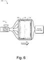
- FIG. 6 depicts a system 600 in an example implementation in which a vacuum device is employed to create negative pressure inside a cavity of the mold 120 to promote flow of the metal alloy 118.
- metal alloys 118 such as one primarily comprised of magnesium may be resistant to flow, especially for thickness that are less than a millimeter. This problem may be exacerbated when confronted with forming an article that is approximately two hundred millimeters long or greater and thus conventional techniques were limited to articles smaller than that.
- a cavity under conventional techniques it may be difficult using conventional techniques to fill a cavity under conventional techniques to form a part of a housing of a computing device that has walls having a thickness of approximately 0.65 millimeters and width and length of greater than 100 millimeters and one hundred and fifty millimeters, respectively (e.g., approximately 190 millimeters by 240 millimeters for a tablet).
- the metal alloy 118 may cool and harden, especially at those thicknesses and lengths due to the large amount of surface area in comparison with thicker and/or shorter articles.
- the techniques described herein may be employed to form such an article.
- a vacuum device 602 is employed to bias a flow of the metal alloy 118 through the cavity 128 to form the article 114.
- the vacuum device 602 may be configured to form negative pressure within the cavity 128 of the mold 120.
- the negative pressure e.g., 0.4 bar
- the negative pressure may include a partial vacuum formed to remove air from the cavity 218, thereby reducing a chance of formation of air pockets as the cavity 128 is filled with the metal alloy 118.
- the vacuum device 602 may be coupled to particular areas of the mold 120 to bias the flow of the metal alloy 118 in desired ways.
- the article 114 may include areas that are feature rich (e.g., as opposed to sections having fewer features, the wall 202, and so on) and thus may restrict flow in those areas. Additionally, particular areas might be further away from an injection port (e.g., at the corners that are located closer to the vacuum device 602 than the injection device 104).
- the vacuum device 602 is coupled to areas that are opposite areas of the mold 120 that receive the metal alloy 118, e.g., from the injection device 104. In this way, the metal alloy 118 is encouraged to flow through the mold 120 and reduce voids formed within the mold 120 due to incomplete flow, air pockets, and so on. Other techniques may also be employed to bias flow of the metal alloy 118, another example of which is described as follows and shown in an associated figure.
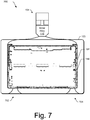
- FIG. 7 depicts a system 700 in an example implementation in which a mold 120 includes one or more overflows 702, 704 to bias a flow of metal alloy 118 through a mold 120.
- characteristics of the article 114 to be molded may cause complications, such as due to relative thinness (e.g., less than one millimeter), length of article (e.g., 100 millimeters or over), shape of article 114 (e.g., to reach corners on the opposing side of the cavity 128 from the injection device 104), features and feature density, and so on. These complications may make it difficult to get the metal alloy 118 to flow to particular portions of the mold 120, such as due to cooling and so forth.
- overflows 702, 704 are utilized to bias flow of the metal alloy 118 towards the overflows 702, 704.
- the overflows 702, 704 are positioned based on feature density of corresponding portions of the cavity 128 of the mold 120.
- the overflows 702, 704, in another example, may bias flow toward the corners of the cavity 128. In this way, a portion of the cavity 128 that may be otherwise difficult to fill may be formed using the metal alloy 118 without introducing voids.
- material e.g., the metal alloy 118
- disposed within the overflows 702, 704 may be removed to form the article 114, such as by a machining operation.
- the overflows 702, 704 may be utilized to counteract a "cold material" condition in which the material (e.g., the metal alloy 118) does not fill the cavity 128 completely, thus forming voids such as pinholes.
- the colder material for instance, may exit the overflows 702, 704 thus promoting contact of hotter material (e.g., metal alloy 118 still in substantially liquid form) to form the article 114. This may also aide a microstructure of the article 114 due to the lack of imperfections as could be encountered otherwise.
- FIG. 8 depicts an example implementation 800 in which a protrusion is utilized to reduce an effect of thermal expansion caused by varying degrees of thickness of an article 114 to be molded.
- injection molding was traditionally utilized to form plastic parts.
- conventional techniques were then expanded to metal alloys, conventional techniques were limited to relatively small sizes (e.g., watch parts) due to thermal expansion of the material, which could cause inconsistencies in articles larger than a relatively small size, e.g., watch parts.
- techniques are described herein which may utilized to counteract differences in thermal expansion, e.g., due to differences in thickness of the article, and as such may be used to support manufacture of larger articles, such as articles over 100 millimeters.
- the example implementation 800 is illustrated using first and second stages 802, 804.
- the mold 120 is shown as forming a cavity 128 to mold an article.
- the cavity 128 is configured to have different thicknesses to mold different parts of the article 114, such as a wall 202 and a feature 206.
- the feature 206 has a thickness that is greater than a thickness of the wall 202. Accordingly, the feature 206 may exhibit a larger amount of contraction than the wall 202 due to thermal expansion of the metal alloy 118.
- this caused a depression in a side of the article that is opposite to the feature 206. This depression made formation of a substantially flat surface on a side of the article that opposed the feature 206 difficult if not impossible using conventional injection molding techniques.
- the cavity 126 of the mold is configured to form a protrusion 806 on an opposing side of the feature.
- the protrusion 806 is shaped and sized based at least in part on thermal expansion (and subsequent contraction) of the metal alloy 118 used to form the article.
- the protrusion 806 may be formed in a variety of ways, such as to have a minimum radius of 0.6 mm, use of angles of thirty degrees or less, and so on.
- the article 114 may form a substantially flat surface that includes an area proximal to an opposing side of the feature as well as the opposing side of the feature 206, e.g., the wall 202 and an opposing side of the feature 206 adjacent to the wall 202.
- the article 114 may be formed to have a substantially flat surface using a mold 120 having a cavity 128 that is not substantially flat at a corresponding portion of the cavity 128 of the mold 120.
- FIG. 9 depicts an example implementation 900 in which a mold is employed that includes edges configured to reduce voids.
- This implementation 900 is also shown using first and second stage 902, 904.
- injection molding was traditionally performed using plastics.
- conventional techniques could be confronted with reduced flow characteristics of the metal alloy 118 in comparison with the plastics, which could cause voids.
- molding portions 124, 126 of the mold 120 are configured to form a cavity 128 as before to mold an article 114.
- the cavity 128 is configured to employ radii and angles that promote flowabilitybetween the surface of the cavity 218 and the metal alloy 118 to form the article 114 without voids.
- the article 114 may be configured to include portions (e.g., a wall) that have a thickness of less than one millimeter, such as approximately 0.65 millimeter. Accordingly, a radius 906 of approximately 0.6 to 1.0 millimeters may be used to form an edge of the article 114. This radius 906 is sufficient to promote flow of a metal alloy 118 comprised primarily of magnesium through the cavity 128 of the mold 120 from the injection device 104 yet still promote contact. Other radii are also contemplated, such as one millimeter, two millimeters, and three millimeters. Additionally, larger radii may be employed with articles having less thickness, such as a radius of approximately twelve millimeters for an article 114 having walls with a thickness of approximately 0.3 millimeters.
- these radii may be employed to follow a likely direction of flow of the metal alloy 118 through the cavity 128 in the mold 120.
- a leading and/or trailing edge of a feature aligned perpendicular to the flow of the metal alloy 118 may employ the radii described above whereas other edges of the feature that run substantially parallel to the flow may employ "sharp" edges that do not employ the radii, e.g., have a radius of less than 0.6 mm for an article 114 having walls with a thickness of approximately 0.65 millimeters.
- the metal alloy 118 may be shaped using the mold 120 as shown in the first stage 902.
- edges of the article 114 may be machined to "sharpen" the edges, e.g., stamping, grinding, cutting, and so on.
- Other examples are also contemplated as further described in the following discussion of the example procedures.
- FIG. 10 depicts a procedure 1000 in an example implementation in which an article is injection molded using a mold that employs overflows.
- An article is injection molded using a metal alloy comprised primarily of magnesium using a molding device having a plurality of molding portions that form a cavity that defines an article to be molded using the metal alloy and one or more overflows that are positioned to bias flow of the metal alloy toward parts of the cavity that correspond to the overflows (block 1002).
- the overflows 702, 704 may be positioned to bias flow towards associated regions of the mold 120.
- the overflows 702, 704 may also be used to remove metal alloy 118 that has cooled during flow through the mold 120 such that subsequent metal alloy that is injected into the mold 120 may remain in a liquid form sufficient to contact the surface of the cavity as opposed to the cooled metal alloy 118 that may cause pin holes and other imperfections.
- the metal alloy collected in the one or more overflows is removed from the metal alloy molded using the cavity to form the article (block 1004). This may be performed using a stamping, machining, or other operation in which the metal alloy 118 disposed in the overflows is separated from the metal alloy 118 in the cavity 128 of the mold 120 that is used to form the article 114, e.g., a housing of a hand-held computing device such as a tablet, phone, and so on.
- FIG. 11 depicts a procedure 1100 in an example implementation in which a mold is formed that employs overflows.
- a mold is formed that includes a plurality of molding portions (block 1102).
- the molding portions may be used to form a cavity that define an article to be molded using a metal alloy (block 1104), such as a metal alloy comprised primarily of magnesium.
- One or more overflows are also formed as part of the molding portions that are positioned to bias flow of the metal alloy injected through the cavity toward parts of the cavity that correspond to the overflows (block 1106). As before, these overflows may be positioned due to feature density of the article, difficult locations of the cavity to fill, located to remove "cooled” metal alloy, and so on.
- FIG. 12 depicts a procedure 1200 in an example implementation in which a protrusion is formed to at least partially counteract thermal expansion of the metal alloy and subsequent contraction caused by cooling of the metal alloy.
- a metal alloy is injected into a mold having a plurality of molding portions that define a cavity that corresponds to an article to be molded.
- the mold defines a portion of the cavity that defines a feature for the article having a thickness that is greater than a thickness of an area of the article defined by the cavity that is proximal to the feature.
- the mold also defines a protrusion for the article aligned as substantially opposing the feature, the protrusion being sized such that upon solidifying of the metal alloy that forms the article, the protrusion reduces an effect of thermal expansion on a portion of the article that is aligned as substantially opposing the feature (block 1202).
- the protrusion for instance, may be formed as an indention in part of the cavity 128 of the mold 120.
- the metal alloy is removed from the cavity of the mold after solidifying of the metal alloy within the mold (block 1204).
- the protrusion may be used to offset an effect of thermal expansion and subsequent contraction of the metal alloy 118, such as to form a substantially flat surface on a side of the article opposite to the feature.
- FIG. 13 depicts a procedure 1300 in an example implementation in which a mold is formed that is configured to form a protrusion on an article to counteract an effect of thermal expansion.
- a mold is formed having a plurality of molding portions to form an article using a metal alloy that is defined in the mold using a cavity (block 1302). This may include forming a portion of the cavity that defines a feature for the article having a thickness that is greater than a thickness of an area of the article defined by the cavity that is proximal to the feature (block 1304).
- the mold may also be configured to form a protrusion for the article aligned on a side of the cavity that is opposite to a side including the feature, the protrusion being sized as being proportional to the thickness of the feature such that upon solidifying of the metal alloy that forms the article, the protrusion reduces an effect of thermal expansion on the side of the article that is opposite to the feature (block 1306). In this way, subsequent cooling of the metal alloy and corresponding contraction may be addressed to reduce the effect of the thermal expansion on the article.
- FIG. 14 depicts a procedure 1400 in an example implementation in which a radius is employed to limit formation of voids of the article.
- a metal alloy is injected into a mold having a plurality of molding portions that define a cavity that corresponds to an article to be molded including walls with a thickness of less than one millimeter with one or more features disposed thereon having edges with a radius of at least 0.6 millimeter (block 1402).
- metal alloys may introduce complications not encountered using plastics, such as quicker cooling and resistance to flow through a mold 120, especially for articles having a thickness of under one millimeter.
- the radius may be employed to reduce voids caused by sharp edges.
- At least a portion of the radius of the edge is machined to define the feature of the article after removal of the metal alloy from the cavity (block 1404). In this way, a sharp edge may be provided on the device yet a likelihood of voids reduced. A variety of other examples are also contemplated as previously described in relation to FIG. 9 .
Landscapes
- Engineering & Computer Science (AREA)
- Mechanical Engineering (AREA)
- Moulds For Moulding Plastics Or The Like (AREA)
- Injection Moulding Of Plastics Or The Like (AREA)
Claims (12)
- Appareil comprenant :un dispositif d'injection (104) configuré pour réaliser un alliage métallique (118) sous pression ; etun dispositif de moulage (106) couplé au dispositif d'injection et ayant une pluralité de portions de moulage (124, 126) qui forment une cavité (128) qui définit un article (114) à mouler en utilisant l'alliage métallique et ayant un élément (206) d'une épaisseur différente d'une paroi (202) de l'article et une saillie (806) faisant face à l'élément, la taille et la forme de la saillie étant basées au moins en partie sur la dilatation thermique de l'alliage métallique pour compenser la contraction de l'article, lors du moulage d'un alliage métallique qui est constitué principalement de magnésium ; etun ou plusieurs trop-pleins (702, 704) qui sont positionnés pour orienter l'écoulement de l'alliage métallique vers une partie de la cavité (128) qui a une plus haute densité d'éléments qu'une autre partie de la cavité.
- Appareil selon la revendication 1, dans lequel au moins un de l'un ou plusieurs trop-pleins (702, 704) est positionné au niveau d'une partie de la cavité (128) qui est plus éloignée d'un point auquel l'alliage métallique (118) est injecté dans la cavité qu'une autre partie de la cavité qui n'est pas disposée de manière proximale par rapport à l'un ou plusieurs trop-pleins.
- Appareil selon la revendication 1, dans lequel au moins l'un de l'un ou plusieurs trop-pleins (702, 704) est positionné au niveau d'une partie de la cavité (128) qui définit des éléments qui provoquent une turbulence accrue dans un écoulement de l'alliage métallique (118) à travers la cavité par rapport à une autre partie de la cavité qui n'est pas disposée de manière proximale par rapport à l'un ou plusieurs trop-pleins.
- Appareil selon la revendication 1, dans lequel l'alliage métallique (118) disposé à l'intérieur du trop-plein (702, 704) dans le dispositif de moulage (106) est configuré pour être retiré pour former l'article (114).
- Procédé comprenant :le moulage par injection (1002) d'un article (114) utilisant un alliage métallique (118) constitué principalement de magnésium en utilisant un dispositif de moulage (106) ayant une pluralité de portions de moulage (124, 126) qui forment :une cavité (128) qui définit l'article à mouler utilisant l'alliage métallique et ayant un élément (206) d'une épaisseur différente d'une paroi (202) de l'article et une saillie (806) faisant face à l'élément, la taille et la forme de la saillie étant basées au moins en partie sur la dilatation thermique de l'alliage métallique pour compenser la contraction de l'article ; etun ou plusieurs trop-pleins (702, 704) qui sont positionnés pour orienter l'écoulement de l'alliage métallique vers une partie de la cavité (128) qui a une plus haute densité d'éléments qu'une autre partie de la cavité ; etle retrait (1004) de l'alliage métallique collecté dans l'un ou plusieurs trop-pleins depuis l'alliage métallique moulé en utilisant la cavité pour former l'article.
- Procédé selon la revendication 5, dans lequel au moins l'un de l'un ou plusieurs trop-pleins (702, 704) est positionné au niveau d'une partie de la cavité (128) qui est plus éloignée d'un point auquel l'alliage métallique (118) est injecté dans la cavité qu'une autre partie de la cavité qui n'est pas disposée de manière proximale par rapport à l'un ou plusieurs trop-pleins.
- Procédé selon la revendication 5, dans lequel au moins l'un de l'un ou plusieurs trop-pleins (702, 704) est positionné au niveau d'une partie de la cavité (128) qui définit des éléments qui provoquent une turbulence accrue dans un écoulement de l'alliage métallique (118) à travers la cavité par rapport à une autre partie de la cavité qui n'est pas disposée de manière proximale par rapport à l'un ou plusieurs trop-pleins.
- Procédé comprenant :la formation (1102) d'un moule (120) comprenant une pluralité de portions de moulage (124, 126), la formation incluant :la formation (1104) d'une cavité (128) en utilisant une ou plusieurs de la pluralité de portions de moulage qui définit un article (114) à mouler en utilisant un alliage métallique (118) et ayant un élément (206) d'une épaisseur différente d'une paroi (202) de l'article et une saillie (806) faisant face à l'élément, la taille et la forme de la saillie étant basées au moins en partie sur la dilatation thermique de l'alliage métallique pour compenser la contraction de l'article ; etla formation (1106) d'un ou plusieurs trop-pleins (702, 704) qui sont positionnés pour orienter l'écoulement de l'alliage métallique injecté à travers la cavité vers une partie de la cavité (128) qui a une plus haute densité d'éléments qu'une autre partie de la cavité.
- Procédé selon la revendication 8, dans lequel au moins l'un de l'un ou plusieurs trop-pleins (702, 704) est positionné au niveau d'une partie de la cavité (128) qui est plus éloignée d'un point auquel l'alliage métallique (118) est injecté dans la cavité qu'une autre partie de la cavité qui n'est pas disposée de manière proximale par rapport à l'un ou plusieurs trop-pleins.
- Procédé selon la revendication 8, dans lequel au moins l'un de l'un ou plusieurs trop-pleins (702, 704) est positionné au niveau d'une partie de la cavité (128) qui définit des éléments qui provoquent une turbulence accrue dans un écoulement de l'alliage métallique à travers la cavité par rapport à une autre partie de la cavité qui n'est pas disposée de manière proximale par rapport à l'un ou plusieurs trop-pleins.
- Procédé selon la revendication 6 ou 8, ou appareil selon la description 1, dans lequel l'article (114) est configuré pour avoir une épaisseur de moins d'un millimètre et pour avoir une longueur d'au moins 100 millimètres.
- Procédé selon la revendication 8, dans lequel l'article (114) est configuré pour avoir des parois ayant une épaisseur d'environ 0,65 millimètre.
Applications Claiming Priority (1)
| Application Number | Priority Date | Filing Date | Title |
|---|---|---|---|
| PCT/CN2012/083085 WO2014059625A1 (fr) | 2012-10-17 | 2012-10-17 | Écoulements de moulage par injection d'alliage métallique |
Publications (3)
| Publication Number | Publication Date |
|---|---|
| EP2908971A1 EP2908971A1 (fr) | 2015-08-26 |
| EP2908971A4 EP2908971A4 (fr) | 2015-11-04 |
| EP2908971B1 true EP2908971B1 (fr) | 2018-01-03 |
Family
ID=50487445
Family Applications (1)
| Application Number | Title | Priority Date | Filing Date |
|---|---|---|---|
| EP12886709.0A Active EP2908971B1 (fr) | 2012-10-17 | 2012-10-17 | Écoulements de moulage par injection d'alliage métallique |
Country Status (4)
| Country | Link |
|---|---|
| US (1) | US9027631B2 (fr) |
| EP (1) | EP2908971B1 (fr) |
| CN (1) | CN104903026B (fr) |
| WO (1) | WO2014059625A1 (fr) |
Families Citing this family (15)
| Publication number | Priority date | Publication date | Assignee | Title |
|---|---|---|---|---|
| US9426905B2 (en) | 2012-03-02 | 2016-08-23 | Microsoft Technology Licensing, Llc | Connection device for computing devices |
| US9158383B2 (en) | 2012-03-02 | 2015-10-13 | Microsoft Technology Licensing, Llc | Force concentrator |
| US9075566B2 (en) | 2012-03-02 | 2015-07-07 | Microsoft Technoogy Licensing, LLC | Flexible hinge spine |
| USRE48963E1 (en) | 2012-03-02 | 2022-03-08 | Microsoft Technology Licensing, Llc | Connection device for computing devices |
| US9360893B2 (en) | 2012-03-02 | 2016-06-07 | Microsoft Technology Licensing, Llc | Input device writing surface |
| US9064654B2 (en) | 2012-03-02 | 2015-06-23 | Microsoft Technology Licensing, Llc | Method of manufacturing an input device |
| US9870066B2 (en) | 2012-03-02 | 2018-01-16 | Microsoft Technology Licensing, Llc | Method of manufacturing an input device |
| US20130300590A1 (en) | 2012-05-14 | 2013-11-14 | Paul Henry Dietz | Audio Feedback |
| US9073123B2 (en) | 2012-06-13 | 2015-07-07 | Microsoft Technology Licensing, Llc | Housing vents |
| US8654030B1 (en) | 2012-10-16 | 2014-02-18 | Microsoft Corporation | Antenna placement |
| EP2908970B1 (fr) | 2012-10-17 | 2018-01-03 | Microsoft Technology Licensing, LLC | Protubérances de moulage par injection d'alliage métallique |
| WO2014059618A1 (fr) | 2012-10-17 | 2014-04-24 | Microsoft Corporation | Formation de graphique par ablation de matériau |
| US9424048B2 (en) | 2014-09-15 | 2016-08-23 | Microsoft Technology Licensing, Llc | Inductive peripheral retention device |
| CN106216628A (zh) * | 2016-08-31 | 2016-12-14 | 天津圣金特汽车配件有限公司 | 一种汽车发动机支架铝合金超低速压铸工艺 |
| ES2631502B1 (es) * | 2016-09-06 | 2018-06-05 | Comercial Nicem-Exinte, S.A - Coniex | Equipo de inyección de metal en molde polimérico, molde polimérico utilizado y procedimiento de funcionamiento del conjunto |
Citations (3)
| Publication number | Priority date | Publication date | Assignee | Title |
|---|---|---|---|---|
| US5340528A (en) * | 1992-02-21 | 1994-08-23 | Sony Corporation | Injection/compression molding method, a die for injection/compression molding and an injection/compression molding machine |
| CN1782112A (zh) * | 2004-10-06 | 2006-06-07 | 国立大学法人东北大学 | 镁合金、成型制品以及镁合金的成型方法 |
| US20080185747A1 (en) * | 2007-02-05 | 2008-08-07 | Canon Kabushiki Kaisha | Injection mold and partial compression molding method |
Family Cites Families (325)
| Publication number | Priority date | Publication date | Assignee | Title |
|---|---|---|---|---|
| GB1100331A (en) | 1964-03-05 | 1968-01-24 | Chloride Overseas Ltd | Improvements relating to moulds for thin castings |
| US3879586A (en) | 1973-10-31 | 1975-04-22 | Essex International Inc | Tactile keyboard switch assembly with metallic or elastomeric type conductive contacts on diaphragm support |
| US4065649A (en) | 1975-06-30 | 1977-12-27 | Lake Center Industries | Pressure sensitive matrix switch having apertured spacer with flexible double sided adhesive intermediate and channels optionally interposed between apertures |
| US4046975A (en) | 1975-09-22 | 1977-09-06 | Chomerics, Inc. | Keyboard switch assembly having internal gas passages preformed in spacer member |
| CA1104182A (fr) | 1977-06-24 | 1981-06-30 | Peter Strandwitz | Interrupteur fonctionnant au toucher |
| JPS54101176A (en) | 1978-01-26 | 1979-08-09 | Shinetsu Polymer Co | Contact member for push switch |
| US4365130A (en) | 1979-10-04 | 1982-12-21 | North American Philips Corporation | Vented membrane switch with contaminant scavenger |
| US4317013A (en) | 1980-04-09 | 1982-02-23 | Oak Industries, Inc. | Membrane switch with universal spacer means |
| JPS56159134U (fr) | 1980-04-23 | 1981-11-27 | ||
| US4559426A (en) | 1980-11-03 | 1985-12-17 | Oak Industries Inc. | Membrane switch and components having means for preventing creep |
| JPS5810335U (ja) | 1981-07-15 | 1983-01-22 | 信越ポリマ−株式会社 | 薄型キ−ボ−ド装置 |
| US4492829A (en) | 1982-02-25 | 1985-01-08 | Rogers Corporation | Tactile membrane keyboard with asymmetrical tactile key elements |
| JPS6098231U (ja) | 1983-12-10 | 1985-07-04 | アルプス電気株式会社 | メンブレンスイツチ |
| US4588187A (en) | 1984-06-27 | 1986-05-13 | Wico Corporation | Port expansion adapter for video game port |
| US4651133A (en) | 1984-12-24 | 1987-03-17 | At&T Technologies, Inc. | Method and apparatus for capacitive keyboard scanning |
| US5021638A (en) | 1987-08-27 | 1991-06-04 | Lucas Duraltih Corporation | Keyboard cover |
| JP2871802B2 (ja) | 1990-04-19 | 1999-03-17 | アルプス電気株式会社 | 照光式キートツプ |
| US6001199A (en) | 1990-10-24 | 1999-12-14 | Hunter Douglas Inc. | Method for manufacturing a fabric light control window covering |
| US5220521A (en) | 1992-01-02 | 1993-06-15 | Cordata Incorporated | Flexible keyboard for computers |
| US6344791B1 (en) | 1998-07-24 | 2002-02-05 | Brad A. Armstrong | Variable sensor with tactile feedback |
| US5331443A (en) | 1992-07-31 | 1994-07-19 | Crown Roll Leaf, Inc. | Laser engraved verification hologram and associated methods |
| US5283559A (en) | 1992-09-21 | 1994-02-01 | International Business Machines Corp. | Automatic calibration of a capacitive touch screen used with a fixed element flat screen display panel |
| US5363075A (en) | 1992-12-03 | 1994-11-08 | Hughes Aircraft Company | Multiple layer microwave integrated circuit module connector assembly |
| WO1995012208A2 (fr) | 1993-10-26 | 1995-05-04 | Marketing Partners, Gesellschaft für Marketing-Projecting und Marketing-Services mbH | Clavier plat de saisie pour appareils de traitement de donnees ou similaires et son procede de fabrication |
| US5681220A (en) | 1994-03-18 | 1997-10-28 | International Business Machines Corporation | Keyboard touchpad combination in a bivalve enclosure |
| JPH07313733A (ja) | 1994-05-25 | 1995-12-05 | Nintendo Co Ltd | 電子ゲーム機およびそれに用いられる本体装置および操作器 |
| US5548477A (en) | 1995-01-27 | 1996-08-20 | Khyber Technologies Corporation | Combination keyboard and cover for a handheld computer |
| US5618232A (en) | 1995-03-23 | 1997-04-08 | Martin; John R. | Dual mode gaming device methods and systems |
| JPH0970644A (ja) | 1995-09-05 | 1997-03-18 | Toyota Motor Corp | 樹脂中子 |
| US5828770A (en) | 1996-02-20 | 1998-10-27 | Northern Digital Inc. | System for determining the spatial position and angular orientation of an object |
| US5781406A (en) | 1996-03-05 | 1998-07-14 | Hunte; Stanley G. | Computer desktop keyboard cover with built-in monitor screen & wrist-support accessory |
| US5940065A (en) | 1996-03-15 | 1999-08-17 | Elo Touchsystems, Inc. | Algorithmic compensation system and method therefor for a touch sensor panel |
| AU2808697A (en) | 1996-04-24 | 1997-11-12 | Logitech, Inc. | Touch and pressure sensing method and apparatus |
| US5745376A (en) | 1996-05-09 | 1998-04-28 | International Business Machines Corporation | Method of detecting excessive keyboard force |
| TW338816B (en) | 1996-08-09 | 1998-08-21 | Sony Co Ltd | Input aparatus |
| US5818361A (en) | 1996-11-07 | 1998-10-06 | Acevedo; Elkin | Display keyboard |
| US6178443B1 (en) | 1996-12-20 | 2001-01-23 | Intel Corporation | Method and apparatus for propagating user preferences across multiple computer environments |
| US5807175A (en) | 1997-01-15 | 1998-09-15 | Microsoft Corporation | Dynamic detection of player actuated digital input devices coupled to a computer port |
| US5874697A (en) | 1997-02-14 | 1999-02-23 | International Business Machines Corporation | Thin keyboard switch assembly with hinged actuator mechanism |
| JPH10326124A (ja) | 1997-05-26 | 1998-12-08 | Hitachi Ltd | 携帯情報端末装置 |
| TW389918B (en) | 1997-08-24 | 2000-05-11 | Sony Computer Entertainment Inc | Game apparatus, game machine manipulation device, game system and interactive communication method for game apparatus |
| TW388894B (en) | 1997-10-09 | 2000-05-01 | Nissha Printing | High strength touch panel and manufacturing method therefor |
| US6005209A (en) | 1997-11-24 | 1999-12-21 | International Business Machines Corporation | Thin keyboard having torsion bar keyswitch hinge members |
| US6040823A (en) | 1997-12-02 | 2000-03-21 | Cts | Computer keyboard having top molded housing with rigid pointing stick integral and normal to front surface of housing as one unit part to be used with strain sensors in navigational control |
| US6061644A (en) | 1997-12-05 | 2000-05-09 | Northern Digital Incorporated | System for determining the spatial position and orientation of a body |
| EP1717684A3 (fr) | 1998-01-26 | 2008-01-23 | Fingerworks, Inc. | Procédé et dispositif d'intégration d'entrée manuelle |
| US6022012A (en) | 1998-03-12 | 2000-02-08 | Hewlett-Packard Company | Modular automatic document feeder for a flat bed input device |
| US6898315B2 (en) | 1998-03-23 | 2005-05-24 | Microsoft Corporation | Feature extraction for real-time pattern recognition using single curve per pattern analysis |
| US5971635A (en) | 1998-05-11 | 1999-10-26 | Music Sales Corporation | Piano-style keyboard attachment for computer keyboard |
| US6603408B1 (en) | 1998-06-01 | 2003-08-05 | Brenda Lewellen Gaba | Flexible membrane keyboard |
| US7268774B2 (en) | 1998-08-18 | 2007-09-11 | Candledragon, Inc. | Tracking motion of a writing instrument |
| US6704864B1 (en) | 1999-08-19 | 2004-03-09 | L.V. Partners, L.P. | Automatic configuration of equipment software |
| US6044717A (en) | 1998-09-28 | 2000-04-04 | Xerox Corporation | Pressure and force profile sensor and method for detecting pressure |
| US6513570B2 (en) * | 1998-10-13 | 2003-02-04 | Water Gremlin Company | Apparatus and method of forming battery parts |
| US6042075A (en) | 1998-11-10 | 2000-03-28 | Burch, Jr.; Warren E. | Computer copy holder for keyboard drawer |
| US6279060B1 (en) | 1998-12-04 | 2001-08-21 | In-System Design, Inc. | Universal serial bus peripheral bridge simulates a device disconnect condition to a host when the device is in a not-ready condition to avoid wasting bus resources |
| US6254105B1 (en) | 1999-04-02 | 2001-07-03 | Elo Touchsystems, Inc. | Sealing system for acoustic wave touchscreens |
| JP2000330096A (ja) | 1999-05-25 | 2000-11-30 | Nec Corp | 液晶表示装置およびその組立方法 |
| JP2001018048A (ja) * | 1999-06-30 | 2001-01-23 | Sony Corp | 低融点金属材料の射出成形方法、射出成形装置及び筐体 |
| US6147859A (en) | 1999-08-18 | 2000-11-14 | Ops, Inc. | Modular external peripheral housing |
| US6532147B1 (en) | 1999-09-24 | 2003-03-11 | International Business Machines Corporation | Flexible monitor/display on mobile device |
| US7123292B1 (en) | 1999-09-29 | 2006-10-17 | Xerox Corporation | Mosaicing images with an offset lens |
| US6725318B1 (en) | 2000-02-29 | 2004-04-20 | Microsoft Corporation | Automated selection between a USB and PS/2 interface for connecting a keyboard to a computer |
| US6543949B1 (en) | 2000-03-23 | 2003-04-08 | Eugene B. Ritchey | Keyboard support apparatus |
| EP1269503A1 (fr) | 2000-03-30 | 2003-01-02 | Eleksen Limited | Dispositif d'entree |
| US6962454B1 (en) | 2000-04-04 | 2005-11-08 | Costello Pamella A | Keyboard protective cover |
| US6313731B1 (en) | 2000-04-20 | 2001-11-06 | Telefonaktiebolaget L.M. Ericsson | Pressure sensitive direction switches |
| US6970957B1 (en) | 2000-04-24 | 2005-11-29 | Microsoft Corporation | Dynamically configuring resources for cycle translation in a computer system |
| US6449147B2 (en) | 2000-05-01 | 2002-09-10 | Patent Category Corp. | Collapsible structures having enhancements |
| LU90578B1 (de) | 2000-05-05 | 2001-11-06 | Iee Sarl | Sensormatte fuer Fahrzeug |
| US6511378B1 (en) | 2000-05-05 | 2003-01-28 | Intel Corporation | Method of identifying game controllers in multi-player game |
| JP2002041231A (ja) | 2000-05-17 | 2002-02-08 | Hitachi Ltd | 画面入力型表示装置 |
| GB2367134B (en) | 2000-05-18 | 2002-09-11 | Electrotextiles Co Ltd | Data input device |
| US6774888B1 (en) | 2000-06-19 | 2004-08-10 | International Business Machines Corporation | Personal digital assistant including a keyboard which also acts as a cover |
| US6329617B1 (en) | 2000-09-19 | 2001-12-11 | Lester E. Burgess | Pressure activated switching device |
| US6784869B1 (en) | 2000-11-15 | 2004-08-31 | The Boeing Company | Cursor and display management system for multi-function control and display system |
| US6600121B1 (en) | 2000-11-21 | 2003-07-29 | Think Outside, Inc. | Membrane switch |
| JP2002160041A (ja) * | 2000-11-24 | 2002-06-04 | Sanyo Electric Co Ltd | 金属薄肉成形体用金型およびそれを用いた金属薄肉成形体の製法 |
| US6617536B2 (en) | 2000-11-29 | 2003-09-09 | Yazaki Corporation | Dome switch |
| US7289083B1 (en) | 2000-11-30 | 2007-10-30 | Palm, Inc. | Multi-sided display for portable computer |
| JP3617958B2 (ja) * | 2001-03-07 | 2005-02-09 | 株式会社東芝 | 表示装置用筐体 |
| US6819316B2 (en) | 2001-04-17 | 2004-11-16 | 3M Innovative Properties Company | Flexible capacitive touch sensor |
| US6894592B2 (en) | 2001-05-18 | 2005-05-17 | Magfusion, Inc. | Micromagnetic latching switch packaging |
| US6585435B2 (en) | 2001-09-05 | 2003-07-01 | Jason Fang | Membrane keyboard |
| KR20040064271A (ko) | 2001-11-09 | 2004-07-16 | 미네베아 가부시키가이샤 | 터치 패널 어셈블리 |
| US7907394B2 (en) | 2001-11-19 | 2011-03-15 | Otter Products, Llc | Protective enclosure for touch screen device |
| US6685369B2 (en) | 2001-12-10 | 2004-02-03 | Andy Lien | Housing assembly for membrane keyboard |
| LU90871B1 (fr) | 2001-12-28 | 2003-06-30 | Iee Sarl | Clavier flexible |
| US6950950B2 (en) | 2001-12-28 | 2005-09-27 | Hewlett-Packard Development Company, L.P. | Technique for conveying overload conditions from an AC adapter to a load powered by the adapter |
| JP2003230951A (ja) * | 2002-02-13 | 2003-08-19 | Olympus Optical Co Ltd | 筒形状部品を成形するための射出成形用金型及び成形品 |
| GB2386346B (en) | 2002-03-12 | 2005-06-15 | Eleksen Ltd | Flexible foldable keyboard |
| US6882337B2 (en) | 2002-04-18 | 2005-04-19 | Microsoft Corporation | Virtual keyboard for touch-typing using audio feedback |
| US7542052B2 (en) | 2002-05-31 | 2009-06-02 | Hewlett-Packard Development Company, L.P. | System and method of switching viewing orientations of a display |
| US6856506B2 (en) | 2002-06-19 | 2005-02-15 | Motion Computing | Tablet computing device with three-dimensional docking support |
| US6776546B2 (en) | 2002-06-21 | 2004-08-17 | Microsoft Corporation | Method and system for using a keyboard overlay with a touch-sensitive display screen |
| JP3476814B1 (ja) * | 2002-06-21 | 2003-12-10 | 宇部興産機械株式会社 | 半溶融金属成形用金型 |
| US7126588B2 (en) | 2002-06-27 | 2006-10-24 | Intel Corporation | Multiple mode display apparatus |
| KR100460956B1 (ko) | 2002-07-03 | 2004-12-09 | 삼성전자주식회사 | 휴대용 정보단말기의 키보드 |
| WO2004008725A1 (fr) | 2002-07-16 | 2004-01-22 | Nokia Corporation | Couverture flexible de telephone mobile |
| US6979799B2 (en) | 2002-07-31 | 2005-12-27 | Illinois Tool Works Inc. | System and method for operating and locking a trigger of a welding gun |
| US7051149B2 (en) | 2002-08-29 | 2006-05-23 | Lite-On Technology Corporation | Method for transceiving non-USB device by an adapter and apparatus using the same |
| US6824321B2 (en) | 2002-09-19 | 2004-11-30 | Siemens Communications, Inc. | Keypad assembly |
| US7253723B2 (en) | 2003-05-19 | 2007-08-07 | Donnelly Corporation | Mirror assembly |
| US6813143B2 (en) | 2002-10-21 | 2004-11-02 | Nokia Corporation | Mobile device featuring 90 degree rotatable front cover for covering or revealing a keyboard |
| US7559834B1 (en) | 2002-12-02 | 2009-07-14 | Microsoft Corporation | Dynamic join/exit of players during play of console-based video game |
| JP4551869B2 (ja) | 2002-12-16 | 2010-09-29 | マイクロソフト コーポレーション | コンピュータ装置とインタフェースをとるシステム及び方法 |
| US7194662B2 (en) | 2003-02-28 | 2007-03-20 | International Business Machines Corporation | Method, apparatus and program storage device for providing data path optimization |
| US8907904B2 (en) | 2010-10-01 | 2014-12-09 | Z124 | Smartpad split screen desktop |
| US6864573B2 (en) | 2003-05-06 | 2005-03-08 | Daimlerchrysler Corporation | Two piece heat sink and device package |
| US7502803B2 (en) | 2003-05-28 | 2009-03-10 | Hewlett-Packard Development Company, L.P. | System and method for generating ACPI machine language tables |
| US7083295B1 (en) | 2003-05-30 | 2006-08-01 | Global Traders And Suppliers, Inc. | Electroluminescent bags |
| DE60335674D1 (de) | 2003-06-12 | 2011-02-17 | Research In Motion Ltd | Mehrelement-Antenne mit schwimmenden parasitären Antennenelement |
| DE10327453A1 (de) | 2003-06-18 | 2005-01-27 | Bayer Materialscience Ag | Verbundsysteme zur Herstellung von dekorierten Kunststoffformteilen und ein Verfahren zur Herstellung der Verbundsysteme |
| US7007125B2 (en) | 2003-06-24 | 2006-02-28 | International Business Machines Corporation | Pass through circuit for reduced memory latency in a multiprocessor system |
| EP1662707B1 (fr) | 2003-07-23 | 2019-10-30 | Sony Interactive Entertainment Inc. | Dispositif de communication, systeme de jeu, procede d'etablissement de liaison, procede de communication, dispositif d'adaptation et systeme de communication |
| US20050059489A1 (en) | 2003-09-12 | 2005-03-17 | Kim Taek Sung | Motion sensing applications |
| US7256768B2 (en) | 2003-09-16 | 2007-08-14 | Microsoft Corporation | Computer keyboard with quantitatively force-sensing keys |
| US7277087B2 (en) | 2003-12-31 | 2007-10-02 | 3M Innovative Properties Company | Touch sensing with touch down and lift off sensitivity |
| US7620244B1 (en) | 2004-01-06 | 2009-11-17 | Motion Computing, Inc. | Methods and systems for slant compensation in handwriting and signature recognition |
| US8117651B2 (en) | 2004-04-27 | 2012-02-14 | Apple Inc. | Method and system for authenticating an accessory |
| WO2005111986A2 (fr) | 2004-05-07 | 2005-11-24 | Infinium Labs, Inc. | Système d’interface utilisateur à niveaux multiples et positions multiples |
| JP4245512B2 (ja) | 2004-05-24 | 2009-03-25 | アルプス電気株式会社 | 入力装置 |
| US7042713B2 (en) | 2004-05-26 | 2006-05-09 | Texas Instruments Incorporated | Slide case with pivotable stand member for handheld computing device |
| US20050264653A1 (en) | 2004-05-27 | 2005-12-01 | Starkweather James A | Portable electronic device with adjustable image capture orientation and method therefore |
| WO2005119404A1 (fr) | 2004-06-01 | 2005-12-15 | Beech Technology Incorporated | Système informatique portable multi-affichage pliant et séparable |
| US7733326B1 (en) | 2004-08-02 | 2010-06-08 | Prakash Adiseshan | Combination mouse, pen-input and pen-computer device |
| US7724242B2 (en) | 2004-08-06 | 2010-05-25 | Touchtable, Inc. | Touch driven method and apparatus to integrate and display multiple image layers forming alternate depictions of same subject matter |
| KR100651938B1 (ko) | 2004-08-16 | 2006-12-06 | 엘지전자 주식회사 | 영상 배향 제어장치, 방법 및 매체 |
| US7667962B2 (en) | 2004-08-20 | 2010-02-23 | Mullen Jeffrey D | Wireless devices with flexible monitors and keyboards |
| US7636921B2 (en) | 2004-09-01 | 2009-12-22 | Ati Technologies Inc. | Software and methods for previewing parameter changes for a graphics display driver |
| TWI265431B (en) | 2004-09-07 | 2006-11-01 | Acer Inc | Notebook computer with antenna array module |
| US7256996B2 (en) | 2004-10-14 | 2007-08-14 | Bountiful Wifi Llc | Wireless router |
| US7392410B2 (en) | 2004-10-15 | 2008-06-24 | Dell Products L.P. | Power adapter having power supply identifier information functionality |
| US7823214B2 (en) | 2005-01-07 | 2010-10-26 | Apple Inc. | Accessory authentication for electronic devices |
| US8369795B2 (en) | 2005-01-12 | 2013-02-05 | Microsoft Corporation | Game console notification system |
| US7639876B2 (en) | 2005-01-14 | 2009-12-29 | Advanced Digital Systems, Inc. | System and method for associating handwritten information with one or more objects |
| GB0503291D0 (en) | 2005-02-17 | 2005-03-23 | Eleksen Ltd | Mobile communication |
| US7499037B2 (en) | 2005-03-29 | 2009-03-03 | Wells Gardner Electronics Corporation | Video display and touchscreen assembly, system and method |
| TW200635474A (en) | 2005-03-30 | 2006-10-01 | Microelectronics Tech Inc | Mold-casting structure and the grounding improvement method thereof |
| US7928964B2 (en) | 2005-04-22 | 2011-04-19 | Microsoft Corporation | Touch input data handling |
| US20070072474A1 (en) | 2005-04-27 | 2007-03-29 | Nigel Beasley | Flexible power adapter systems and methods |
| US7337085B2 (en) | 2005-06-10 | 2008-02-26 | Qsi Corporation | Sensor baseline compensation in a force-based touch device |
| US7447934B2 (en) | 2005-06-27 | 2008-11-04 | International Business Machines Corporation | System and method for using hot plug configuration for PCI error recovery |
| GB0515175D0 (en) | 2005-07-25 | 2005-08-31 | Plastic Logic Ltd | Flexible resistive touch screen |
| US20070062089A1 (en) | 2005-08-31 | 2007-03-22 | Homer Steven S | Display device |
| KR100723903B1 (ko) | 2005-11-11 | 2007-06-04 | 후지쯔 가부시끼가이샤 | 전자기기 |
| JP4694388B2 (ja) | 2006-02-28 | 2011-06-08 | 任天堂株式会社 | タッチパネルを用いた入力装置 |
| US7656392B2 (en) | 2006-03-24 | 2010-02-02 | Synaptics Incorporated | Touch sensor effective area enhancement |
| JP2007272341A (ja) | 2006-03-30 | 2007-10-18 | Toshiba Corp | 演算装置、演算装置システムおよび電力制御方法 |
| US20070260892A1 (en) | 2006-05-08 | 2007-11-08 | Paul Christopher R | System and method for authenticating a power source |
| JP4216865B2 (ja) | 2006-05-29 | 2009-01-28 | 株式会社東芝 | 通信可能な情報機器 |
| US7827426B2 (en) | 2006-06-05 | 2010-11-02 | Tte Technology Inc. | Low power mode override system and method |
| US20080005423A1 (en) | 2006-06-06 | 2008-01-03 | Robert Alan Jacobs | Method and device for acting on stylus removal |
| US7326864B2 (en) | 2006-06-07 | 2008-02-05 | International Business Machines Corporation | Method and apparatus for masking keystroke sounds from computer keyboards |
| US8169421B2 (en) | 2006-06-19 | 2012-05-01 | Cypress Semiconductor Corporation | Apparatus and method for detecting a touch-sensor pad gesture |
| JP2008000807A (ja) * | 2006-06-26 | 2008-01-10 | Fujitsu Ltd | 金型鋳造法に使用する金型、当該金型を使用した制振部材の製造方法 |
| US7944520B2 (en) | 2006-08-11 | 2011-05-17 | Sharp Kabushiki Kaisha | Liquid crystal display device and electronic apparatus provided with same |
| US7813715B2 (en) | 2006-08-30 | 2010-10-12 | Apple Inc. | Automated pairing of wireless accessories with host devices |
| JP2008061342A (ja) | 2006-08-30 | 2008-03-13 | Mitsumi Electric Co Ltd | 電子システム、電子装置および電源装置 |
| US8046619B2 (en) | 2006-10-03 | 2011-10-25 | Avaya Inc. | Apparatus and methods for data distribution devices having selectable power supplies |
| KR101330121B1 (ko) | 2006-10-30 | 2013-11-26 | 삼성전자주식회사 | 컴퓨터시스템 및 그 제어방법 |
| US8781522B2 (en) | 2006-11-02 | 2014-07-15 | Qualcomm Incorporated | Adaptable antenna system |
| US7973771B2 (en) | 2007-04-12 | 2011-07-05 | 3M Innovative Properties Company | Touch sensor with electrode array |
| US20080151478A1 (en) | 2006-12-21 | 2008-06-26 | Jr-Jiun Chern | Hinge for laptop computer |
| US8026904B2 (en) | 2007-01-03 | 2011-09-27 | Apple Inc. | Periodic sensor panel baseline adjustment |
| US8054296B2 (en) | 2007-01-03 | 2011-11-08 | Apple Inc. | Storing baseline information in EEPROM |
| US8130203B2 (en) | 2007-01-03 | 2012-03-06 | Apple Inc. | Multi-touch input discrimination |
| US8462109B2 (en) | 2007-01-05 | 2013-06-11 | Invensense, Inc. | Controlling and accessing content using motion processing on mobile devices |
| KR20080064424A (ko) | 2007-01-05 | 2008-07-09 | 삼성전자주식회사 | 연성 표시부를 구비한 폴딩형 휴대 통신 장치 |
| US20080238884A1 (en) | 2007-03-29 | 2008-10-02 | Divyasimha Harish | Edge sensors forming a touchscreen |
| US7946774B2 (en) | 2007-04-16 | 2011-05-24 | The Matias Corporation | Folding keyboard with numeric keypad |
| WO2008137553A1 (fr) | 2007-05-01 | 2008-11-13 | Hewlett-Packard Development Company, L.P. | Commande bidirectionnelle d'un adaptateur de puissance et d'une charge |
| US7639329B2 (en) | 2007-05-01 | 2009-12-29 | Nitto Denko Corporation | Liquid crystal panel and liquid crystal display apparatus |
| US7884807B2 (en) | 2007-05-15 | 2011-02-08 | Synaptics Incorporated | Proximity sensor and method for indicating a display orientation change |
| JP5218402B2 (ja) | 2007-05-18 | 2013-06-26 | 株式会社セガ | デジタイザ機能付液晶表示装置、情報処理用電子機器及びゲーム装置 |
| US8416197B2 (en) | 2007-06-15 | 2013-04-09 | Ricoh Co., Ltd | Pen tracking and low latency display updates on electronic paper displays |
| US8059101B2 (en) | 2007-06-22 | 2011-11-15 | Apple Inc. | Swipe gestures for touch screen keyboards |
| US8078787B2 (en) | 2007-06-22 | 2011-12-13 | Apple Inc. | Communication between a host device and an accessory via an intermediate device |
| US8086781B2 (en) | 2007-06-22 | 2011-12-27 | Apple Inc. | Serial pass-through device |
| US20080316002A1 (en) | 2007-06-25 | 2008-12-25 | Brunet Peter T | Pre-configuration of user preferences |
| US8065624B2 (en) | 2007-06-28 | 2011-11-22 | Panasonic Corporation | Virtual keypad systems and methods |
| US8014138B2 (en) | 2007-07-05 | 2011-09-06 | Daley Iii Charles A | Bag computer manual character input device and cover |
| KR101354372B1 (ko) | 2007-07-31 | 2014-01-23 | 삼성전자주식회사 | 인쇄회로기판 보강구조물 및 이를 이용한 집적회로 패키지 |
| US8099144B2 (en) | 2007-08-20 | 2012-01-17 | Google Inc. | Electronic device with hinge mechanism |
| US7932890B2 (en) | 2007-08-30 | 2011-04-26 | Citizen Electronics Co., Ltd. | Lightguide plate and electronic device |
| JP4643624B2 (ja) | 2007-09-21 | 2011-03-02 | 株式会社東芝 | アンテナ装置、および電子機器 |
| KR100938684B1 (ko) | 2007-10-16 | 2010-01-25 | 코오롱글로텍주식회사 | 전자 원단 및 이의 제조방법 |
| US9723709B2 (en) | 2007-10-22 | 2017-08-01 | Todd Steigerwald | Method for assigning control channels |
| US20090262492A1 (en) | 2007-10-26 | 2009-10-22 | Seal Shield, Llc | Submersible keyboard |
| US8488306B2 (en) | 2007-11-08 | 2013-07-16 | Sideline, Inc. | Secondary computing device display system |
| US8232977B2 (en) | 2007-11-14 | 2012-07-31 | N-Trig Ltd. | System and method for detection with a digitizer sensor |
| US20120094257A1 (en) | 2007-11-15 | 2012-04-19 | Electronic Brailler | Remote braille education system and device |
| US20090140985A1 (en) | 2007-11-30 | 2009-06-04 | Eric Liu | Computing device that determines and uses applied pressure from user interaction with an input interface |
| JP4292224B2 (ja) * | 2007-12-14 | 2009-07-08 | 株式会社東芝 | 金型、鋳造品の製造方法 |
| WO2009084080A1 (fr) | 2007-12-27 | 2009-07-09 | Panasonic Corporation | Système d'affichage vidéo, dispositif d'affichage, module d'extension et procédé de commande d'alimentation du module d'extension |
| US8154527B2 (en) | 2008-01-04 | 2012-04-10 | Tactus Technology | User interface system |
| US8456438B2 (en) | 2008-01-04 | 2013-06-04 | Tactus Technology, Inc. | User interface system |
| US20090174679A1 (en) | 2008-01-04 | 2009-07-09 | Wayne Carl Westerman | Selective Rejection of Touch Contacts in an Edge Region of a Touch Surface |
| US8403576B2 (en) | 2008-01-07 | 2013-03-26 | Google Inc. | Keyboard for hand held computing device |
| WO2009088245A2 (fr) | 2008-01-11 | 2009-07-16 | Clavier pliable pour ordinateur portable | |
| JP5171282B2 (ja) | 2008-01-21 | 2013-03-27 | キヤノン株式会社 | 像振れ補正装置、撮像装置、光学装置および像振れ補正装置の制御方法 |
| US8464078B2 (en) | 2008-01-22 | 2013-06-11 | Hewlett-Packard Development Company, L.P. | Delay circuit with reset feature |
| US8310444B2 (en) | 2008-01-29 | 2012-11-13 | Pacinian Corporation | Projected field haptic actuation |
| JP4384228B2 (ja) | 2008-01-31 | 2009-12-16 | 株式会社東芝 | 金型、および鋳造品の製造方法 |
| JP2009208085A (ja) * | 2008-02-29 | 2009-09-17 | Toshiba Corp | 金型、および鋳造製品の製造方法 |
| JP2009251895A (ja) | 2008-04-04 | 2009-10-29 | Sony Corp | 電力交換装置、電力交換方法、プログラム、および電力交換システム |
| KR101051311B1 (ko) | 2008-04-22 | 2011-07-22 | 한국과학기술원 | 직물형 입력장치 |
| JP2009296377A (ja) | 2008-06-05 | 2009-12-17 | Toshiba Corp | 電子機器 |
| US8154524B2 (en) | 2008-06-24 | 2012-04-10 | Microsoft Corporation | Physics simulation-based interaction for surface computing |
| US20090321490A1 (en) | 2008-06-27 | 2009-12-31 | Microsoft Corporation | Laptop computer carrier |
| US7975348B2 (en) | 2008-06-27 | 2011-07-12 | Shin Zu Shing Co., Ltd. | Pivoting slide hinge |
| WO2009155951A1 (fr) | 2008-06-27 | 2009-12-30 | Nokia Corporation | Dispositif électronique portable avec une pluralité de configurations articulées et procédé associé |
| US7817428B2 (en) | 2008-06-27 | 2010-10-19 | Greer Jr David Randall | Enclosure with integrated heat wick |
| US20090321034A1 (en) * | 2008-06-30 | 2009-12-31 | Kabushiki Kaisha Toshiba | Die and method of manufacturing cast product |
| US8842076B2 (en) | 2008-07-07 | 2014-09-23 | Rockstar Consortium Us Lp | Multi-touch touchscreen incorporating pen tracking |
| US9335868B2 (en) | 2008-07-31 | 2016-05-10 | Apple Inc. | Capacitive sensor behind black mask |
| US20100038821A1 (en) | 2008-08-18 | 2010-02-18 | Microsoft Corporation | Tactile Enhancement For Input Devices |
| TWI382591B (zh) | 2008-08-20 | 2013-01-11 | Asustek Comp Inc | 平板天線與無線通訊裝置 |
| US20100045609A1 (en) | 2008-08-20 | 2010-02-25 | International Business Machines Corporation | Method for automatically configuring an interactive device based on orientation of a user relative to the device |
| US8536471B2 (en) | 2008-08-25 | 2013-09-17 | N-Trig Ltd. | Pressure sensitive stylus for a digitizer |
| JP5079646B2 (ja) | 2008-08-26 | 2012-11-21 | 新光電気工業株式会社 | 半導体パッケージ及びその製造方法と半導体装置 |
| TWI367442B (en) | 2008-08-27 | 2012-07-01 | Au Optronics Corp | Touch panel |
| US20100051432A1 (en) | 2008-09-04 | 2010-03-04 | Goda Technology Co., Ltd. | Membrane type computer keyboard |
| US8023261B2 (en) | 2008-09-05 | 2011-09-20 | Apple Inc. | Electronic device assembly |
| US8382059B2 (en) | 2008-09-09 | 2013-02-26 | Zero Chroma, LLC | Holder for electronic device with support |
| US7978281B2 (en) | 2008-09-16 | 2011-07-12 | General Dynamics Land Systems | Low stress mounting support for ruggedized displays |
| US8059039B2 (en) | 2008-09-25 | 2011-11-15 | Apple Inc. | Clutch barrel antenna for wireless electronic devices |
| US8688037B2 (en) | 2008-09-26 | 2014-04-01 | Hewlett-Packard Development Company, L.P. | Magnetic latching mechanism for use in mating a mobile computing device to an accessory device |
| US20100085321A1 (en) | 2008-10-03 | 2010-04-08 | Mark Stephen Pundsack | Small touch sensitive interface allowing selection of multiple functions |
| US20100092790A1 (en) * | 2008-10-14 | 2010-04-15 | Gm Global Technology Operations, Inc. | Molded or extruded combinations of light metal alloys and high-temperature polymers |
| EP2187290A1 (fr) | 2008-11-18 | 2010-05-19 | Studer Professional Audio GmbH | Dispositif d'entrée et procédé de détection d'une entrée d'utilisateur avec un dispositif d'entrée |
| WO2010060211A1 (fr) | 2008-11-28 | 2010-06-03 | Nortel Networks Limited | Procédé et appareil de commande d'une vue de caméra dans un environnement virtuel généré par ordinateur en trois dimensions |
| US7945717B2 (en) | 2008-12-09 | 2011-05-17 | Symbol Technologies, Inc. | Method and apparatus for providing USB pass through connectivity |
| US9684375B2 (en) | 2008-12-12 | 2017-06-20 | Immersion Corporation | Systems and methods for stabilizing a haptic touch panel or touch surface |
| US8674941B2 (en) | 2008-12-16 | 2014-03-18 | Dell Products, Lp | Systems and methods for implementing haptics for pressure sensitive keyboards |
| US8250001B2 (en) | 2008-12-18 | 2012-08-21 | Motorola Mobility Llc | Increasing user input accuracy on a multifunctional electronic device |
| US8248371B2 (en) | 2008-12-19 | 2012-08-21 | Verizon Patent And Licensing Inc. | Accelerometer sensitive soft input panel |
| JP2010154205A (ja) | 2008-12-25 | 2010-07-08 | Panasonic Corp | 携帯無線機 |
| CN101465107B (zh) | 2008-12-31 | 2010-12-08 | 华为终端有限公司 | 一种显示装置、使用该显示装置的终端及显示方法 |
| US8441441B2 (en) | 2009-01-06 | 2013-05-14 | Qualcomm Incorporated | User interface for mobile devices |
| US20100188299A1 (en) | 2009-01-07 | 2010-07-29 | Audiovox Corporation | Laptop computer antenna device |
| US8902191B2 (en) | 2009-01-28 | 2014-12-02 | Synaptics Incorporated | Proximity sensing for capacitive touch sensors |
| GB2479312B (en) | 2009-01-30 | 2013-05-29 | Hewlett Packard Development Co | Integrated-circuit attachment structure with solder balls and pins |
| CN101807134B (zh) | 2009-02-13 | 2011-12-07 | 太瀚科技股份有限公司 | 电磁感应系统及单边坐标定位方法 |
| TWI406004B (zh) | 2009-02-19 | 2013-08-21 | Largan Precision Co Ltd | 成像光學透鏡組 |
| US8229509B2 (en) | 2009-02-27 | 2012-07-24 | Microsoft Corporation | Protective shroud for handheld device |
| US8565829B2 (en) | 2009-03-02 | 2013-10-22 | Lg Electronics Inc. | Mobile terminal with detachably coupled sub-device |
| WO2010101961A2 (fr) | 2009-03-02 | 2010-09-10 | Apple Inc. | Techniques de renforcement de protections en verre pour dispositifs électroniques portables |
| NO332210B1 (no) | 2009-03-23 | 2012-07-30 | Cisco Systems Int Sarl | Grensesnittenhet mellom videokonferansekodek og interaktiv whiteboard-tavle |
| US20100231461A1 (en) | 2009-03-13 | 2010-09-16 | Qualcomm Incorporated | Frequency selective multi-band antenna for wireless communication devices |
| GB2487617B (en) | 2009-03-18 | 2014-03-12 | Sierra Wireless Inc | Multiple antenna system for wireless communication |
| JP5493739B2 (ja) | 2009-03-19 | 2014-05-14 | ソニー株式会社 | センサ装置及び情報処理装置 |
| JP2010257325A (ja) | 2009-04-27 | 2010-11-11 | Sony Corp | 制御システム、操作装置および制御方法 |
| US8246467B2 (en) | 2009-04-29 | 2012-08-21 | Apple Inc. | Interactive gaming with co-located, networked direction and location aware devices |
| CN102422504A (zh) | 2009-05-18 | 2012-04-18 | 波士顿电力公司 | 可充电电池的能量效率及快速充电模式 |
| US8861737B2 (en) | 2009-05-28 | 2014-10-14 | Qualcomm Incorporated | Trust establishment from forward link only to non-forward link only devices |
| KR20100128702A (ko) | 2009-05-29 | 2010-12-08 | 삼성전자주식회사 | 두 개의 터치스크린 디스플레이 패널을 구비한 휴대단말기 |
| US9058063B2 (en) | 2009-05-30 | 2015-06-16 | Sony Computer Entertainment Inc. | Tracking system calibration using object position and orientation |
| US9383881B2 (en) | 2009-06-03 | 2016-07-05 | Synaptics Incorporated | Input device and method with pressure-sensitive layer |
| US20100315348A1 (en) | 2009-06-11 | 2010-12-16 | Motorola, Inc. | Data entry-enhancing touch screen surface |
| US20100325155A1 (en) | 2009-06-23 | 2010-12-23 | James Skinner | Systems and Methods for Providing Access to Various Files Across a Network |
| US20100331059A1 (en) | 2009-06-30 | 2010-12-30 | Jeffrey Apgar | Apparatus with swivel hinge and associated method |
| US8568184B2 (en) | 2009-07-15 | 2013-10-29 | Apple Inc. | Display modules |
| US9430078B2 (en) | 2009-08-12 | 2016-08-30 | Google Technology Holdings LLC | Printed force sensor within a touch screen |
| US20110069148A1 (en) | 2009-09-22 | 2011-03-24 | Tenebraex Corporation | Systems and methods for correcting images in a multi-sensor system |
| KR20120098725A (ko) | 2009-10-19 | 2012-09-05 | 바이엘 머티리얼사이언스 아게 | 햅틱 피드백을 위한 굴곡 조립체 및 고정장치 |
| CN102096490A (zh) | 2009-12-09 | 2011-06-15 | 华硕电脑股份有限公司 | 控制触控模块的方法及电子装置 |
| US20120256959A1 (en) | 2009-12-30 | 2012-10-11 | Cywee Group Limited | Method of controlling mobile device with touch-sensitive display and motion sensor, and mobile device |
| US8543745B2 (en) | 2010-01-06 | 2013-09-24 | Apple Inc. | Accessory for a portable computing device |
| US8432368B2 (en) | 2010-01-06 | 2013-04-30 | Qualcomm Incorporated | User interface methods and systems for providing force-sensitive input |
| US8756445B2 (en) | 2010-01-06 | 2014-06-17 | Apple Inc. | Providing power to an accessory during portable computing device hibernation |
| US8213168B2 (en) | 2010-01-06 | 2012-07-03 | Apple Inc. | Assembly of a display module |
| US8069356B2 (en) | 2010-01-06 | 2011-11-29 | Apple Inc. | Accessory power management |
| WO2011088147A2 (fr) | 2010-01-12 | 2011-07-21 | Sensitronics, LLC | Procédé et appareil pour détection tactile multipoint |
| US8396661B2 (en) | 2010-01-26 | 2013-03-12 | Hewlett-Packard Development Company, L.P. | Using relative position data in a mobile computing device |
| US20110179864A1 (en) | 2010-01-27 | 2011-07-28 | Stmicroelectronics, Inc. | Dual accelerometer detector for clamshell devices |
| ITPD20100002U1 (it) | 2010-02-03 | 2011-08-04 | Ursus S P A | Struttura perfezionata di reggiciclo telescopico |
| US20110193787A1 (en) | 2010-02-10 | 2011-08-11 | Kevin Morishige | Input mechanism for providing dynamically protruding surfaces for user interaction |
| US20110205372A1 (en) | 2010-02-25 | 2011-08-25 | Ivan Miramontes | Electronic device and method of use |
| US20110242138A1 (en) | 2010-03-31 | 2011-10-06 | Tribble Guy L | Device, Method, and Graphical User Interface with Concurrent Virtual Keyboards |
| US20110248920A1 (en) | 2010-04-09 | 2011-10-13 | Microsoft Corporation | Keyboard with hinged keys and display functionality |
| US20110261001A1 (en) | 2010-04-23 | 2011-10-27 | Jin Liu | Apparatus and method for impact resistant touchscreen display module |
| US8173893B2 (en) | 2010-05-28 | 2012-05-08 | Yao-Hung Huang | Electronic device case |
| BR112012028204A2 (pt) | 2010-06-07 | 2016-12-06 | Targus Group Internat Inc | acessórios de envoltório de dispositivo eletrônico portátil e sistemas e métodos relacionados |
| US20110304577A1 (en) | 2010-06-11 | 2011-12-15 | Sp Controls, Inc. | Capacitive touch screen stylus |
| US8674959B2 (en) | 2010-06-28 | 2014-03-18 | Intel Corporation | Dynamic bezel for a mobile device |
| USD659139S1 (en) | 2010-07-08 | 2012-05-08 | Zagg Intellectual Property Holding Co., Inc. | Protective cover, including keyboard, for mobile computing device |
| US8754862B2 (en) | 2010-07-11 | 2014-06-17 | Lester F. Ludwig | Sequential classification recognition of gesture primitives and window-based parameter smoothing for high dimensional touchpad (HDTP) user interfaces |
| US8780002B2 (en) | 2010-07-15 | 2014-07-15 | Sony Corporation | Multiple-input multiple-output (MIMO) multi-band antennas with a conductive neutralization line for signal decoupling |
| TW201205626A (en) | 2010-07-30 | 2012-02-01 | Primax Electronics Ltd | Dual force sensing keyboard |
| TW201207698A (en) | 2010-08-05 | 2012-02-16 | Young Lighting Technology Corp | Touch keyboard and electronic device |
| AU2011292026B2 (en) | 2010-08-17 | 2014-08-07 | Google Llc | Touch-based gesture detection for a touch-sensitive device |
| US8561207B2 (en) | 2010-08-20 | 2013-10-15 | Apple Inc. | Authenticating a multiple interface device on an enumerated bus |
| US8638549B2 (en) | 2010-08-24 | 2014-01-28 | Apple Inc. | Electronic device display module |
| US20120092324A1 (en) | 2010-10-18 | 2012-04-19 | Qualcomm Mems Technologies, Inc. | Touch, handwriting and fingerprint sensor with elastomeric spacer layer |
| JP5794809B2 (ja) | 2010-10-29 | 2015-10-14 | ミネベア株式会社 | 入力装置 |
| US9363005B2 (en) | 2010-11-05 | 2016-06-07 | Apple Inc. | Adaptive antenna diversity system |
| KR101777376B1 (ko) | 2010-11-08 | 2017-09-11 | 삼성전자주식회사 | 데이터 저장 장치 및 그것의 구동 방법 |
| US8531418B2 (en) | 2010-11-22 | 2013-09-10 | Integrated Device Technology Inc | Touch sensor having improved edge response |
| US8760349B2 (en) | 2010-11-26 | 2014-06-24 | Intel Corporation | Method and apparatus for in-mold laminate antennas |
| US8467186B2 (en) | 2010-12-07 | 2013-06-18 | Adonit Co. Ltd. | Tablet PC cover with integral keyboard |
| JP5656599B2 (ja) | 2010-12-09 | 2015-01-21 | キヤノン株式会社 | スイッチユニット |
| US8681501B2 (en) | 2010-12-17 | 2014-03-25 | Aruba Networks, Inc. | Heat dissipation unit for a wireless network device |
| JP5310715B2 (ja) | 2010-12-28 | 2013-10-09 | ブラザー工業株式会社 | 画像記録装置及びプログラム |
| USD636397S1 (en) | 2010-12-28 | 2011-04-19 | Andrew Green | Computer stand |
| US8665160B2 (en) | 2011-01-31 | 2014-03-04 | Apple Inc. | Antenna, shielding and grounding |
| US9335793B2 (en) | 2011-01-31 | 2016-05-10 | Apple Inc. | Cover attachment with flexible display |
| WO2012128893A1 (fr) | 2011-02-24 | 2012-09-27 | Cypress Semiconductor Corporation | Capteur tactile monocouche |
| US8896488B2 (en) | 2011-03-01 | 2014-11-25 | Apple Inc. | Multi-element antenna structure with wrapped substrate |
| JP4960515B1 (ja) | 2011-03-18 | 2012-06-27 | 株式会社東芝 | 電子機器 |
| US8521942B2 (en) | 2011-03-21 | 2013-08-27 | Microsoft Corporation | HID over simple peripheral buses |
| US20120274811A1 (en) | 2011-04-28 | 2012-11-01 | Dmitry Bakin | Imaging devices having arrays of image sensors and precision offset lenses |
| WO2012162386A1 (fr) | 2011-05-23 | 2012-11-29 | 360Brandvision, LLC | Accessoire pour réfléchir une image à partir de l'écran d'affichage d'un dispositif électronique portatif |
| US8748767B2 (en) | 2011-05-27 | 2014-06-10 | Dell Products Lp | Sub-membrane keycap indicator |
| CN102955588A (zh) | 2011-08-17 | 2013-03-06 | 天津富纳源创科技有限公司 | 触控式键盘及其制造方法 |
| US8907752B2 (en) | 2011-09-12 | 2014-12-09 | Justin Richard Wodrich | Integrated inductive charging in protective cover |
| US20130076635A1 (en) | 2011-09-26 | 2013-03-28 | Ko Ja (Cayman) Co., Ltd. | Membrane touch keyboard structure for notebook computers |
| US20130229366A1 (en) | 2012-03-02 | 2013-09-05 | Rajesh Manohar Dighde | Support for an Optically Bonded Display Device |
| US9158383B2 (en) | 2012-03-02 | 2015-10-13 | Microsoft Technology Licensing, Llc | Force concentrator |
| US9064654B2 (en) | 2012-03-02 | 2015-06-23 | Microsoft Technology Licensing, Llc | Method of manufacturing an input device |
| US9073123B2 (en) | 2012-06-13 | 2015-07-07 | Microsoft Technology Licensing, Llc | Housing vents |
| US8654030B1 (en) | 2012-10-16 | 2014-02-18 | Microsoft Corporation | Antenna placement |
| WO2014059618A1 (fr) | 2012-10-17 | 2014-04-24 | Microsoft Corporation | Formation de graphique par ablation de matériau |
| EP2908970B1 (fr) | 2012-10-17 | 2018-01-03 | Microsoft Technology Licensing, LLC | Protubérances de moulage par injection d'alliage métallique |
| WO2014059619A1 (fr) | 2012-10-17 | 2014-04-24 | Microsoft Corporation | Profil d'objet pour usinage d'objet |
-
2012
- 2012-10-17 WO PCT/CN2012/083085 patent/WO2014059625A1/fr active Application Filing
- 2012-10-17 EP EP12886709.0A patent/EP2908971B1/fr active Active
- 2012-10-17 CN CN201280076467.3A patent/CN104903026B/zh active Active
- 2012-12-14 US US13/715,229 patent/US9027631B2/en not_active Expired - Fee Related
Patent Citations (3)
| Publication number | Priority date | Publication date | Assignee | Title |
|---|---|---|---|---|
| US5340528A (en) * | 1992-02-21 | 1994-08-23 | Sony Corporation | Injection/compression molding method, a die for injection/compression molding and an injection/compression molding machine |
| CN1782112A (zh) * | 2004-10-06 | 2006-06-07 | 国立大学法人东北大学 | 镁合金、成型制品以及镁合金的成型方法 |
| US20080185747A1 (en) * | 2007-02-05 | 2008-08-07 | Canon Kabushiki Kaisha | Injection mold and partial compression molding method |
Also Published As
| Publication number | Publication date |
|---|---|
| WO2014059625A1 (fr) | 2014-04-24 |
| EP2908971A1 (fr) | 2015-08-26 |
| CN104903026B (zh) | 2017-10-24 |
| CN104903026A (zh) | 2015-09-09 |
| US20140166227A1 (en) | 2014-06-19 |
| EP2908971A4 (fr) | 2015-11-04 |
| US9027631B2 (en) | 2015-05-12 |
Similar Documents
| Publication | Publication Date | Title |
|---|---|---|
| EP2908971B1 (fr) | Écoulements de moulage par injection d'alliage métallique | |
| EP2908970B1 (fr) | Protubérances de moulage par injection d'alliage métallique | |
| EP2908972B1 (fr) | Moulage par injection d'alliage métallique | |
| US20190291322A1 (en) | Reusable mold for injection molding and molding method | |
| CN106976187B (zh) | 一种多曲面闭角结构飞机复合材料零件成型工装 | |
| US8894399B2 (en) | Injection molding tool with integrated gate removal for high-volume manufacturing | |
| US20140150982A1 (en) | Metal Alloy Injection Techniques | |
| WO2014059621A1 (fr) | Techniques d'injection d'alliage métallique | |
| EP3708332B1 (fr) | Dispositif pour démouler des négatifs dans des moules de moulage par injection thermoplastique | |
| CN207014701U (zh) | 一种管夹成型模具 | |
| Hu et al. | Effect of packing parameters and gate size on shrinkage of aspheric lens parts | |
| CN211105349U (zh) | 一种出风口前排叶片的模具 | |
| JP2017217850A (ja) | 厚肉成形品の成形方法 | |
| CN207072091U (zh) | 用于制造管夹的模具 | |
| JPH0586732B2 (fr) | ||
| JPH081722A (ja) | Lim成形方法 | |
| JPH06143352A (ja) | サイドゲートブロック切断式射出成形用金型 | |
| Iwami et al. | An advanced cavity/core system mold for ultra-low pressure injection molding-'ULPAC mold'. | |
| US20110147997A1 (en) | Injection molding device | |
| JP2005238856A (ja) | 射出成形方法 | |
| JPH0715320U (ja) | 射出成形用金型 | |
| JP2006212924A (ja) | 成形型と樹脂成形方法 | |
| JP2002160274A (ja) | プラスチック製眼鏡レンズの射出成形方法 | |
| TH104193A (th) | วิธีการหล่อฉีดและอุปกรณ์การหล่อฉีด |
Legal Events
| Date | Code | Title | Description |
|---|---|---|---|
| PUAI | Public reference made under article 153(3) epc to a published international application that has entered the european phase |
Free format text: ORIGINAL CODE: 0009012 |
|
| 17P | Request for examination filed |
Effective date: 20150416 |
|
| AK | Designated contracting states |
Kind code of ref document: A1 Designated state(s): AL AT BE BG CH CY CZ DE DK EE ES FI FR GB GR HR HU IE IS IT LI LT LU LV MC MK MT NL NO PL PT RO RS SE SI SK SM TR |
|
| AX | Request for extension of the european patent |
Extension state: BA ME |
|
| RA4 | Supplementary search report drawn up and despatched (corrected) |
Effective date: 20151006 |
|
| RIC1 | Information provided on ipc code assigned before grant |
Ipc: B22D 17/20 20060101ALI20150930BHEP Ipc: B22D 17/08 20060101ALI20150930BHEP Ipc: B22D 17/14 20060101AFI20150930BHEP Ipc: B22D 17/22 20060101ALI20150930BHEP Ipc: B22D 17/32 20060101ALI20150930BHEP Ipc: B22D 17/00 20060101ALI20150930BHEP |
|
| 17Q | First examination report despatched |
Effective date: 20151103 |
|
| DAX | Request for extension of the european patent (deleted) | ||
| GRAP | Despatch of communication of intention to grant a patent |
Free format text: ORIGINAL CODE: EPIDOSNIGR1 |
|
| INTG | Intention to grant announced |
Effective date: 20170811 |
|
| GRAS | Grant fee paid |
Free format text: ORIGINAL CODE: EPIDOSNIGR3 |
|
| GRAA | (expected) grant |
Free format text: ORIGINAL CODE: 0009210 |
|
| AK | Designated contracting states |
Kind code of ref document: B1 Designated state(s): AL AT BE BG CH CY CZ DE DK EE ES FI FR GB GR HR HU IE IS IT LI LT LU LV MC MK MT NL NO PL PT RO RS SE SI SK SM TR |
|
| REG | Reference to a national code |
Ref country code: GB Ref legal event code: FG4D |
|
| REG | Reference to a national code |
Ref country code: CH Ref legal event code: EP Ref country code: AT Ref legal event code: REF Ref document number: 959751 Country of ref document: AT Kind code of ref document: T Effective date: 20180115 |
|
| REG | Reference to a national code |
Ref country code: IE Ref legal event code: FG4D |
|
| REG | Reference to a national code |
Ref country code: NL Ref legal event code: FP |
|
| REG | Reference to a national code |
Ref country code: DE Ref legal event code: R096 Ref document number: 602012041728 Country of ref document: DE |
|
| REG | Reference to a national code |
Ref country code: LT Ref legal event code: MG4D |
|
| REG | Reference to a national code |
Ref country code: AT Ref legal event code: MK05 Ref document number: 959751 Country of ref document: AT Kind code of ref document: T Effective date: 20180103 |
|
| PG25 | Lapsed in a contracting state [announced via postgrant information from national office to epo] |
Ref country code: ES Free format text: LAPSE BECAUSE OF FAILURE TO SUBMIT A TRANSLATION OF THE DESCRIPTION OR TO PAY THE FEE WITHIN THE PRESCRIBED TIME-LIMIT Effective date: 20180103 Ref country code: NO Free format text: LAPSE BECAUSE OF FAILURE TO SUBMIT A TRANSLATION OF THE DESCRIPTION OR TO PAY THE FEE WITHIN THE PRESCRIBED TIME-LIMIT Effective date: 20180403 Ref country code: HR Free format text: LAPSE BECAUSE OF FAILURE TO SUBMIT A TRANSLATION OF THE DESCRIPTION OR TO PAY THE FEE WITHIN THE PRESCRIBED TIME-LIMIT Effective date: 20180103 Ref country code: CY Free format text: LAPSE BECAUSE OF FAILURE TO SUBMIT A TRANSLATION OF THE DESCRIPTION OR TO PAY THE FEE WITHIN THE PRESCRIBED TIME-LIMIT Effective date: 20180103 Ref country code: FI Free format text: LAPSE BECAUSE OF FAILURE TO SUBMIT A TRANSLATION OF THE DESCRIPTION OR TO PAY THE FEE WITHIN THE PRESCRIBED TIME-LIMIT Effective date: 20180103 Ref country code: LT Free format text: LAPSE BECAUSE OF FAILURE TO SUBMIT A TRANSLATION OF THE DESCRIPTION OR TO PAY THE FEE WITHIN THE PRESCRIBED TIME-LIMIT Effective date: 20180103 |
|
| PG25 | Lapsed in a contracting state [announced via postgrant information from national office to epo] |
Ref country code: IS Free format text: LAPSE BECAUSE OF FAILURE TO SUBMIT A TRANSLATION OF THE DESCRIPTION OR TO PAY THE FEE WITHIN THE PRESCRIBED TIME-LIMIT Effective date: 20180503 Ref country code: BG Free format text: LAPSE BECAUSE OF FAILURE TO SUBMIT A TRANSLATION OF THE DESCRIPTION OR TO PAY THE FEE WITHIN THE PRESCRIBED TIME-LIMIT Effective date: 20180403 Ref country code: PL Free format text: LAPSE BECAUSE OF FAILURE TO SUBMIT A TRANSLATION OF THE DESCRIPTION OR TO PAY THE FEE WITHIN THE PRESCRIBED TIME-LIMIT Effective date: 20180103 Ref country code: GR Free format text: LAPSE BECAUSE OF FAILURE TO SUBMIT A TRANSLATION OF THE DESCRIPTION OR TO PAY THE FEE WITHIN THE PRESCRIBED TIME-LIMIT Effective date: 20180404 Ref country code: AT Free format text: LAPSE BECAUSE OF FAILURE TO SUBMIT A TRANSLATION OF THE DESCRIPTION OR TO PAY THE FEE WITHIN THE PRESCRIBED TIME-LIMIT Effective date: 20180103 Ref country code: SE Free format text: LAPSE BECAUSE OF FAILURE TO SUBMIT A TRANSLATION OF THE DESCRIPTION OR TO PAY THE FEE WITHIN THE PRESCRIBED TIME-LIMIT Effective date: 20180103 Ref country code: LV Free format text: LAPSE BECAUSE OF FAILURE TO SUBMIT A TRANSLATION OF THE DESCRIPTION OR TO PAY THE FEE WITHIN THE PRESCRIBED TIME-LIMIT Effective date: 20180103 Ref country code: RS Free format text: LAPSE BECAUSE OF FAILURE TO SUBMIT A TRANSLATION OF THE DESCRIPTION OR TO PAY THE FEE WITHIN THE PRESCRIBED TIME-LIMIT Effective date: 20180103 |
|
| REG | Reference to a national code |
Ref country code: FR Ref legal event code: PLFP Year of fee payment: 7 |
|
| REG | Reference to a national code |
Ref country code: DE Ref legal event code: R097 Ref document number: 602012041728 Country of ref document: DE |
|
| PG25 | Lapsed in a contracting state [announced via postgrant information from national office to epo] |
Ref country code: EE Free format text: LAPSE BECAUSE OF FAILURE TO SUBMIT A TRANSLATION OF THE DESCRIPTION OR TO PAY THE FEE WITHIN THE PRESCRIBED TIME-LIMIT Effective date: 20180103 Ref country code: IT Free format text: LAPSE BECAUSE OF FAILURE TO SUBMIT A TRANSLATION OF THE DESCRIPTION OR TO PAY THE FEE WITHIN THE PRESCRIBED TIME-LIMIT Effective date: 20180103 Ref country code: AL Free format text: LAPSE BECAUSE OF FAILURE TO SUBMIT A TRANSLATION OF THE DESCRIPTION OR TO PAY THE FEE WITHIN THE PRESCRIBED TIME-LIMIT Effective date: 20180103 Ref country code: RO Free format text: LAPSE BECAUSE OF FAILURE TO SUBMIT A TRANSLATION OF THE DESCRIPTION OR TO PAY THE FEE WITHIN THE PRESCRIBED TIME-LIMIT Effective date: 20180103 |
|
| PLBE | No opposition filed within time limit |
Free format text: ORIGINAL CODE: 0009261 |
|
| STAA | Information on the status of an ep patent application or granted ep patent |
Free format text: STATUS: NO OPPOSITION FILED WITHIN TIME LIMIT |
|
| PG25 | Lapsed in a contracting state [announced via postgrant information from national office to epo] |
Ref country code: CZ Free format text: LAPSE BECAUSE OF FAILURE TO SUBMIT A TRANSLATION OF THE DESCRIPTION OR TO PAY THE FEE WITHIN THE PRESCRIBED TIME-LIMIT Effective date: 20180103 Ref country code: SK Free format text: LAPSE BECAUSE OF FAILURE TO SUBMIT A TRANSLATION OF THE DESCRIPTION OR TO PAY THE FEE WITHIN THE PRESCRIBED TIME-LIMIT Effective date: 20180103 Ref country code: SM Free format text: LAPSE BECAUSE OF FAILURE TO SUBMIT A TRANSLATION OF THE DESCRIPTION OR TO PAY THE FEE WITHIN THE PRESCRIBED TIME-LIMIT Effective date: 20180103 Ref country code: DK Free format text: LAPSE BECAUSE OF FAILURE TO SUBMIT A TRANSLATION OF THE DESCRIPTION OR TO PAY THE FEE WITHIN THE PRESCRIBED TIME-LIMIT Effective date: 20180103 |
|
| 26N | No opposition filed |
Effective date: 20181005 |
|
| PG25 | Lapsed in a contracting state [announced via postgrant information from national office to epo] |
Ref country code: SI Free format text: LAPSE BECAUSE OF FAILURE TO SUBMIT A TRANSLATION OF THE DESCRIPTION OR TO PAY THE FEE WITHIN THE PRESCRIBED TIME-LIMIT Effective date: 20180103 |
|
| REG | Reference to a national code |
Ref country code: CH Ref legal event code: PL |
|
| REG | Reference to a national code |
Ref country code: BE Ref legal event code: MM Effective date: 20181031 |
|
| PG25 | Lapsed in a contracting state [announced via postgrant information from national office to epo] |
Ref country code: LU Free format text: LAPSE BECAUSE OF NON-PAYMENT OF DUE FEES Effective date: 20181017 Ref country code: MC Free format text: LAPSE BECAUSE OF FAILURE TO SUBMIT A TRANSLATION OF THE DESCRIPTION OR TO PAY THE FEE WITHIN THE PRESCRIBED TIME-LIMIT Effective date: 20180103 |
|
| REG | Reference to a national code |
Ref country code: IE Ref legal event code: MM4A |
|
| PG25 | Lapsed in a contracting state [announced via postgrant information from national office to epo] |
Ref country code: LI Free format text: LAPSE BECAUSE OF NON-PAYMENT OF DUE FEES Effective date: 20181031 Ref country code: BE Free format text: LAPSE BECAUSE OF NON-PAYMENT OF DUE FEES Effective date: 20181031 Ref country code: CH Free format text: LAPSE BECAUSE OF NON-PAYMENT OF DUE FEES Effective date: 20181031 |
|
| PG25 | Lapsed in a contracting state [announced via postgrant information from national office to epo] |
Ref country code: IE Free format text: LAPSE BECAUSE OF NON-PAYMENT OF DUE FEES Effective date: 20181017 |
|
| REG | Reference to a national code |
Ref country code: DE Ref legal event code: R082 Ref document number: 602012041728 Country of ref document: DE |
|
| PG25 | Lapsed in a contracting state [announced via postgrant information from national office to epo] |
Ref country code: MT Free format text: LAPSE BECAUSE OF NON-PAYMENT OF DUE FEES Effective date: 20181017 |
|
| PG25 | Lapsed in a contracting state [announced via postgrant information from national office to epo] |
Ref country code: TR Free format text: LAPSE BECAUSE OF FAILURE TO SUBMIT A TRANSLATION OF THE DESCRIPTION OR TO PAY THE FEE WITHIN THE PRESCRIBED TIME-LIMIT Effective date: 20180103 |
|
| PG25 | Lapsed in a contracting state [announced via postgrant information from national office to epo] |
Ref country code: PT Free format text: LAPSE BECAUSE OF FAILURE TO SUBMIT A TRANSLATION OF THE DESCRIPTION OR TO PAY THE FEE WITHIN THE PRESCRIBED TIME-LIMIT Effective date: 20180103 |
|
| PG25 | Lapsed in a contracting state [announced via postgrant information from national office to epo] |
Ref country code: HU Free format text: LAPSE BECAUSE OF FAILURE TO SUBMIT A TRANSLATION OF THE DESCRIPTION OR TO PAY THE FEE WITHIN THE PRESCRIBED TIME-LIMIT; INVALID AB INITIO Effective date: 20121017 Ref country code: MK Free format text: LAPSE BECAUSE OF NON-PAYMENT OF DUE FEES Effective date: 20180103 |
|
| P01 | Opt-out of the competence of the unified patent court (upc) registered |
Effective date: 20230501 |
|
| PGFP | Annual fee paid to national office [announced via postgrant information from national office to epo] |
Ref country code: NL Payment date: 20230922 Year of fee payment: 12 Ref country code: GB Payment date: 20230920 Year of fee payment: 12 |
|
| PGFP | Annual fee paid to national office [announced via postgrant information from national office to epo] |
Ref country code: FR Payment date: 20230920 Year of fee payment: 12 |
|
| PGFP | Annual fee paid to national office [announced via postgrant information from national office to epo] |
Ref country code: DE Payment date: 20230920 Year of fee payment: 12 |