EP2908320B1 - Transformator mit Isolationsstruktur und Verfahren zur Herstellung eines Transformators mit Isolationsstruktur - Google Patents
Transformator mit Isolationsstruktur und Verfahren zur Herstellung eines Transformators mit Isolationsstruktur Download PDFInfo
- Publication number
- EP2908320B1 EP2908320B1 EP14155017.8A EP14155017A EP2908320B1 EP 2908320 B1 EP2908320 B1 EP 2908320B1 EP 14155017 A EP14155017 A EP 14155017A EP 2908320 B1 EP2908320 B1 EP 2908320B1
- Authority
- EP
- European Patent Office
- Prior art keywords
- transformer
- winding
- insulation structure
- transformer core
- preformed
- Prior art date
- Legal status (The legal status is an assumption and is not a legal conclusion. Google has not performed a legal analysis and makes no representation as to the accuracy of the status listed.)
- Active
Links
- 238000009413 insulation Methods 0.000 title claims description 181
- 238000004519 manufacturing process Methods 0.000 title claims description 11
- 238000004804 winding Methods 0.000 claims description 231
- 238000000034 method Methods 0.000 claims description 24
- 239000000126 substance Substances 0.000 claims description 15
- 150000001875 compounds Chemical class 0.000 claims description 13
- 238000001746 injection moulding Methods 0.000 claims description 6
- 230000004907 flux Effects 0.000 claims description 5
- 238000005266 casting Methods 0.000 claims description 4
- 238000002955 isolation Methods 0.000 description 52
- 238000004382 potting Methods 0.000 description 11
- 238000007373 indentation Methods 0.000 description 10
- 239000000463 material Substances 0.000 description 10
- 238000002347 injection Methods 0.000 description 6
- 239000007924 injection Substances 0.000 description 6
- 230000015572 biosynthetic process Effects 0.000 description 5
- 239000002775 capsule Substances 0.000 description 5
- 230000015556 catabolic process Effects 0.000 description 3
- 238000000465 moulding Methods 0.000 description 3
- 229920001169 thermoplastic Polymers 0.000 description 3
- 239000004416 thermosoftening plastic Substances 0.000 description 3
- 238000013461 design Methods 0.000 description 2
- 238000004512 die casting Methods 0.000 description 2
- 239000011810 insulating material Substances 0.000 description 2
- 239000012774 insulation material Substances 0.000 description 2
- 238000012986 modification Methods 0.000 description 2
- 230000004048 modification Effects 0.000 description 2
- 241000234282 Allium Species 0.000 description 1
- 235000002732 Allium cepa var. cepa Nutrition 0.000 description 1
- 230000002411 adverse Effects 0.000 description 1
- 238000004891 communication Methods 0.000 description 1
- 239000002131 composite material Substances 0.000 description 1
- 238000010276 construction Methods 0.000 description 1
- 230000001419 dependent effect Effects 0.000 description 1
- 239000012530 fluid Substances 0.000 description 1
- 238000003780 insertion Methods 0.000 description 1
- 230000037431 insertion Effects 0.000 description 1
- 230000001788 irregular Effects 0.000 description 1
- 238000005304 joining Methods 0.000 description 1
- 239000007788 liquid Substances 0.000 description 1
- 230000002093 peripheral effect Effects 0.000 description 1
- 239000004033 plastic Substances 0.000 description 1
- 210000002105 tongue Anatomy 0.000 description 1
Images


Classifications
-
- H—ELECTRICITY
- H01—ELECTRIC ELEMENTS
- H01F—MAGNETS; INDUCTANCES; TRANSFORMERS; SELECTION OF MATERIALS FOR THEIR MAGNETIC PROPERTIES
- H01F27/00—Details of transformers or inductances, in general
- H01F27/28—Coils; Windings; Conductive connections
- H01F27/32—Insulating of coils, windings, or parts thereof
- H01F27/324—Insulation between coil and core, between different winding sections, around the coil; Other insulation structures
-
- H—ELECTRICITY
- H01—ELECTRIC ELEMENTS
- H01F—MAGNETS; INDUCTANCES; TRANSFORMERS; SELECTION OF MATERIALS FOR THEIR MAGNETIC PROPERTIES
- H01F17/00—Fixed inductances of the signal type
- H01F17/04—Fixed inductances of the signal type with magnetic core
- H01F17/06—Fixed inductances of the signal type with magnetic core with core substantially closed in itself, e.g. toroid
- H01F17/062—Toroidal core with turns of coil around it
-
- H—ELECTRICITY
- H01—ELECTRIC ELEMENTS
- H01F—MAGNETS; INDUCTANCES; TRANSFORMERS; SELECTION OF MATERIALS FOR THEIR MAGNETIC PROPERTIES
- H01F27/00—Details of transformers or inductances, in general
- H01F27/02—Casings
-
- H—ELECTRICITY
- H01—ELECTRIC ELEMENTS
- H01F—MAGNETS; INDUCTANCES; TRANSFORMERS; SELECTION OF MATERIALS FOR THEIR MAGNETIC PROPERTIES
- H01F27/00—Details of transformers or inductances, in general
- H01F27/28—Coils; Windings; Conductive connections
-
- H—ELECTRICITY
- H01—ELECTRIC ELEMENTS
- H01F—MAGNETS; INDUCTANCES; TRANSFORMERS; SELECTION OF MATERIALS FOR THEIR MAGNETIC PROPERTIES
- H01F27/00—Details of transformers or inductances, in general
- H01F27/28—Coils; Windings; Conductive connections
- H01F27/2823—Wires
-
- H—ELECTRICITY
- H01—ELECTRIC ELEMENTS
- H01F—MAGNETS; INDUCTANCES; TRANSFORMERS; SELECTION OF MATERIALS FOR THEIR MAGNETIC PROPERTIES
- H01F27/00—Details of transformers or inductances, in general
- H01F27/28—Coils; Windings; Conductive connections
- H01F27/2895—Windings disposed upon ring cores
-
- H—ELECTRICITY
- H01—ELECTRIC ELEMENTS
- H01F—MAGNETS; INDUCTANCES; TRANSFORMERS; SELECTION OF MATERIALS FOR THEIR MAGNETIC PROPERTIES
- H01F27/00—Details of transformers or inductances, in general
- H01F27/34—Special means for preventing or reducing unwanted electric or magnetic effects, e.g. no-load losses, reactive currents, harmonics, oscillations, leakage fields
- H01F27/346—Preventing or reducing leakage fields
-
- H—ELECTRICITY
- H01—ELECTRIC ELEMENTS
- H01F—MAGNETS; INDUCTANCES; TRANSFORMERS; SELECTION OF MATERIALS FOR THEIR MAGNETIC PROPERTIES
- H01F30/00—Fixed transformers not covered by group H01F19/00
- H01F30/06—Fixed transformers not covered by group H01F19/00 characterised by the structure
- H01F30/16—Toroidal transformers
-
- H—ELECTRICITY
- H01—ELECTRIC ELEMENTS
- H01F—MAGNETS; INDUCTANCES; TRANSFORMERS; SELECTION OF MATERIALS FOR THEIR MAGNETIC PROPERTIES
- H01F5/00—Coils
- H01F5/02—Coils wound on non-magnetic supports, e.g. formers
Definitions
- the present invention relates to a transformer having a preformed insulation structure and to a method of manufacturing a transformer with a preformed insulation structure.
- Such devices are used, for example, in isolating transformers in which high voltages are applied between a primary winding and a secondary winding.
- Transformers and in particular isolation transformers may comprise a transformer core and at least two windings.
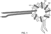
- the windings are wound in a bifilar arrangement.
- An exemplary bifilar array is shown in FIG FIG. 1 shown.
- Two windings 102, 103 formed by wires are wound around an annular transformer core 101 in multiple turns.
- both windings 102, 103 may extend substantially along the entire circumference of the annular transformer core 101 to limit stray inductances.
- the insulation resistance between the first winding 102 and the second winding 103 is determined in this arrangement essentially by the distance and the insulation resistance of the wires forming the windings.
- the two windings of a transformer may each be wound on a different segment along the circumference of an annular transformer core (eg, along a 120 ° segment).
- a distance between the first and second windings can be increased.
- the stray inductance of the windings may increase and also entail an increased dimension of the transformer core and the entire transformer because no windings are wound on a portion of the transformer core.
- the German utility model no. 25 49 379 discloses a transformer using at least one toroidal core provided with a first winding and a second winding separated therefrom by an insulating layer, the toroid wound with the first winding being surrounded by an insulating jacket, leaving the second winding, leaving an opening concentric with the toroidal bore is provided, wherein one of two equal semi-cylindrical shells, which are made via a plane parallel to the core axis separating plane and produced by plastic injection molding, existing capsule for receiving the first winding provided with ring core (t) is provided that each capsule half away from the parting plane, circumferentially directed and towards the apex of a half freely extending with the capsule halves integral resilient tongues for centering the ring core and that the distance of the second winding of the Ringkernbohrungswand only by concentric to the toroidal bore ent symbolize, provided with a reduced clear width circular inner boundary of the capsule faces is set.
- the capsule halves have openings for the introduction of
- the present invention is defined on the one hand by a transformer according to claim 1.
- a compact transformer By using a preformed insulation structure, a compact transformer can be constructed that is easy to manufacture.
- the preformed insulation structure determines by their dimensions a minimum distance between the first and second windings.
- a minimum value for the dielectric strength between the first and the second winding is reliably determined by the insulation structure.
- an arrangement of the first and second windings in two different levels can be achieved. This arrangement can assure a compact construction while keeping the stray inductance of the device low.
- the insulating structure is preformed (that is, it is substantially stable even in an isolated state as it is in the composite transformer), the assembling of the transformer can be facilitated.
- the second winding can be wound directly around the preformed insulation structure.
- the preformed insulation structure remains substantially dimensionally stable when the second wire is wound around it.
- the first and second shells are identically shaped.
- the preformed insulation structure is configured to completely enclose the transformer core or the transformer core with the first winding
- the holes are round, oval, triangular, rectangular or polygonal, or have an irregular shape.
- the preformed insulation structure has more than ten holes.
- the one or more holes cover more than 10% of the surface of the preformed insulation structure.
- a ninth transformer according to any one of the sixth to eighth transformers, those are arranged so that when the transformer core and the first winding are disposed within the preformed insulation structure, the entire space not occupied by the transformer core or the transformer core and the first winding within the preformed insulation structure the outer space is in fluid communication through the holes.
- the transformer further comprises a housing configured to receive the transformer core, the first and second windings, and the preformed isolation structure.
- An eleventh transformer according to the tenth transformer further comprises an insulating substance within the housing enclosing the transformer core and the first and second windings.
- the insulating substance is selected from a potting compound, an oil or a gas.
- the holes in the preformed insulating structure are arranged so that an inside of the housing can be filled with the insulating substance without forming cavities when the transformer core, the first and second windings and the first and second shells are disposed in the housing.
- the housing has one or more protrusions for spacing the preformed insulation structure from one or more outer walls of the housing.
- the preformed insulation structure defines a closed area.
- one or more sides of the closed surface formed by the preformed insulation structure are open to the transformer core and the first winding.
- the preformed insulation structure is in the form of a toroid.
- the preformed insulation structure defines a passage through which the second wire can be wound around the transformer core.
- the first and / or second windings extend at least 300 ° along the transformer core.
- the transformer core is annular.
- the first and / or second windings extend for at most 175 ° along the transformer core.
- a twenty-second transformer according to any one of the preceding transformers comprises a third wire forming a third winding, the third winding being wound around the transformer core.
- the preformed isolation structure is disposed between the transformer core and the third winding.
- a twenty-fourth transformer according to the twenty-second or twenty-third transformer further comprises one or more further wires forming one or more further windings, with one or more windings wound around the transformer core.
- the first winding extends at least 300 ° along the transformer core and the second and one or more further windings each extend across a different segment of the transformer core and are spaced apart from one another.
- the transformer includes another first winding extending over at least 300 ° deg along the transformer core and wound on a plane with the first winding.
- the first winding is a primary winding and the second and further windings are secondary winding.
- the transformer core defines a first plane in or parallel to which the magnetic flux of the transformer core passes during operation of the transformer, and wherein the preformed isolation structure is disposed between the first and second windings, such that the second Winding in a second direction, which is perpendicular to the first plane, is spaced from the first winding and the transformer core.
- the preformed insulation structure is made by an injection molding process.
- the preformed insulation structure comprises a thermoplastic.
- the preformed insulation structure comprises a material having a dielectric constant of 1 to 10 at 0 to 10 MHz.
- a second preformed isolation structure is disposed between the second and third windings, spacing the third winding from the second winding and the first winding and the transformer core.
- the preformed insulation structure comprises one or more wire holders in which the first, the second wire or both, and optionally any other wire can be fixed.
- the preformed isolation structure includes one or more positioning structures configured to position the preformed isolation structure within the housing in one or more directions.
- one or more positioning structures include protrusions disposed on a surface of the preformed insulation structure.
- the protrusions are sized such that a distance of the second winding from one or more side surfaces of the housing is constant.
- the preformed insulation structure and the housing are made of the same material.
- the preformed insulation structure has winding aids for the first wire, the second wire, or both.
- the present invention is defined by a method of manufacturing a transformer according to claim 12.
- a second method according to the first method comprises further arranging the transformer core with the first and second windings and the preformed insulation structure in a housing and pouring the housing with an insulating substance, wherein the preformed insulation structure comprises the holes, so that the insulation substance without the formation of voids the Can fill housing.
- the step of pouring the housing is performed under negative pressure.
- the step of pouring the housing includes a die-casting method.
- the preformed insulation structure comprises one or more wire holders, the method further comprising fixing a first part of the second wire in the wire holder before the step of winding the second wire around the preformed insulation structure and fixing one second part of the second wire in the wire holder after the step of winding the second wire around the preformed insulation structure.
- a sixth method according to the fifth method further comprises inserting the transformer cores having the first winding into a shell of the preformed insulation structure, fixing one or more parts of the first wire, and, after fixing the one or more parts of the first wire, connecting the first shell with the second shell of the preformed insulation structure.
- references to “an embodiment,” “an embodiment,” “example,” or “example” means that a particular feature, structure, or characteristic described in connection with this embodiment, in at least one embodiment of the present invention.
- the phrases “in one embodiment,” “in one embodiment,” “an example,” or “in an example” throughout the specification do not necessarily all refer to the same embodiment or example.
- the particular features, structures, or properties may be combined in any suitable combinations and / or subcombinations in one or more embodiments or examples.
- Particular features, structures, or properties may be included in an integrated circuit, in an electronic circuit, in circuit logic, or in other suitable components that provide the described functionality.
- the drawings are included in the interest of explanation by those skilled in the art and that the drawings are not necessarily drawn to scale.
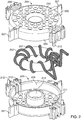
- FIGS. 2 to 4 show various views of a preformed isolation structure configured to complicate a second winding 203 of a first winding 202 and a transformer core 201.
- the first and second windings 202, 203 each include one or more windings.
- the exemplary preformed insulation structure is in two parts and consists of a first shell 204 and a second shell 205.
- the transformer core 201 passes through the first winding 202, which is formed by a first wire.
- the first winding 202 is wound around the transformer core 201.
- the first winding 202 is not necessarily wound directly around the transformer core 201.
- the first and second shells 204, 205 are configured to be assembled to enclose the transformer core 201 and portions of the first winding 202 (in other examples, the first and second shells 204, 205 are configured to support only the first and second windings 202) Enclose transformer core).
- FIG. 3 shows the first and second shells 204, 205 in an assembled state. In this example, the first and second shells 204, 205 form a cylindrical receptacle for the transformer core 201 and parts of the first coil 202.
- the cylindrical shape of the receptacle formed by the first and second shells 204, 205 is not mandatory. So the recording can also have various other forms (for example, it may have the shape of a torus). This applies not only to two-part insulation structures, but also to one-piece insulation structures or insulation structures with more than two parts.
- the first and second shells 204, 205 are further configured to allow a second wire to be wrapped around the first and second shells 204, 205.
- a second winding 203 is formed.
- the first and second shells 204, 205 in the example of FIGS. 2 to 4 an inner wall 214.
- the second wire in these examples is tightly wound between the top 210 and bottom 211 of the insulation structure.
- the second wire 203 is wound between the top 210 and the bottom 211 through a hole formed by the inner wall 214.
- the first and second shells 204, 205, the first and second windings 202, 203, and the transformer core 201 may form an isolation transformer.
- the shells 204, 205 a predetermined Minimum distance of the first winding 202 and the second winding 203 sure. This minimum distance also provides a minimum dielectric strength of the assembly (which is also dictated by the material properties of the material from which the first and second shells 204, 205 are made).
- an insulating layer of the wires may be thinner compared to transformers in which no preformed insulation structure having first and second shells is used (in some examples, even wires with an insulating film may be used).
- the diameter of the wires can be reduced and the flexibility of the wires increased, which can facilitate the winding of the windings.
- the distance of the first and second windings can be precisely predetermined.
- the entire structure can remain compact, since less excess insulation material is introduced.
- the first and second windings are essentially wound around the entire transformer core. By this measure, leakage inductances can be reduced.
- the in the FIGS. 2 to 4 The arrangement shown has a two-part isolation structure.
- the preformed isolation structure may be in one piece.
- the preformed insulation structure may be substantially cylindrical and have an opening for insertion of the transformer core with the first winding. This opening can be arranged in a side wall of the cylindrical insulation structure.
- the one-piece preformed isolation structure may consist of a single shell. The tightly wound with a first winding wrestlers can be inserted into the single shell, so that a sufficient distance between the first winding and the upper edge of the side wall of the shell of the preformed insulation structure results. The second winding is tightly wrapped around the one-piece insulation structure.
- the preformed insulation structure may be multi-part.
- each of the shells can be made from the FIGS. 2 to 4 be composed of two or more parts.
- the first and second shells 204, 205 enclose the transformer core 201 and parts of the first coil 202 completely from all sides.
- preformed insulation structure forms a substantially cylindrical receptacle for the transformer core 201 and parts of the first winding 202.
- the shells 204, 205 each form a circular top or bottom 210, 211 of the cylindrical receptacle and a circumferential side wall 209th
- first and second shells 204, 205 may form a top or bottom side 210, 211 of a cylindrical receptacle.
- the circumferential side wall 209 may be partially omitted. In such a recording would be in a FIGS. 3 and 4 corresponding view of the transformer core (partially) visible. Nevertheless, such a receptacle can ensure that a second winding is reliably spaced from the first winding and from the transformer core.
- a second wire may be wrapped sufficiently taut over the top and bottom of the cylindrical receptacle, respectively, so as to maintain a predetermined distance from portions of the first winding surrounding the transformer core (which in turn may be tightly wrapped around the transformer core), although the preformed insulation structure does not completely surround the transformer core.
- the arrangement just described is not limited to cylindrical recordings.
- top and / or bottom 210, 211 of a cylindrical receptacle may be partially omitted.
- a recording would be in a FIGS. 3 and 4 corresponding view also the transformer core (partially) visible.
- a receptacle can ensure that a second winding is reliably spaced from the first winding and from the transformer core.
- the second wire may be wound around the circumferential side wall 209, the inner wall 214, and around the top and bottom 210, 211 in such an isolation structure.
- the arrangement just described is not limited to cylindrical recordings.
- FIGS. 2 to 4 Although shown trays form a top 210 and a bottom 211 of a recording. However, these top 210 and bottom 211 are interspersed with a plurality of holes 206 (the holes will be described in detail below). Thus, also in the FIGS. 2 to 4 shown shells in the region of the holes 206, the second winding are stretched over the holes, that a predetermined distance to possibly below the holes 206 wound first winding 202 is observed.
- isolation structure has a plurality of optional connectors, each comprising a pin 212 and a corresponding recess 213 to receive a pin.
- a pin 212 is disposed on one of the shells 204, 205 and the corresponding recess 213 on the other shell 204, 205.
- the first and second Shells 204, 205 interconnects.
- structures may be provided that snap into one another or a hinge that hingedly connects the first and second shells.
- the arrangement of the connecting elements may be chosen so that the two or more parts of the insulating structure can be connected only in one way or in several equivalent ways.
- FIGS. 2 to 4 In the example of FIGS. 2 to 4 is ensured by the arrangement of two pins / depressions at two opposite points of the shells 204, 205 and only one pin / a recess at two other points that the shells 204, 205 can be assembled only in two ways. This can be avoided that the shells (or other multi-part Isolation structures) are incorrectly assembled and under certain circumstances, the second winding must be removed again to correct the error.
- FIGS. 2 to 4 it has been explained how a preformed insulation structure can accommodate a transformer core and object to a second winding from a first winding and the transformer core.
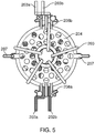
- FIG. 5 will be further optional features in the FIGS. 2 to 4 shown shells 204, 205 explained.
- these features are not limited to two-piece isolation structures with trays. Rather, they can also be used in other isolation structures.
- the isolation structure may include one or more wire retainers 208a, 208b.
- two wire holders 208a, 208b are disposed on opposite sides of the first and second shells 204, 205.
- a first wire holder 208a is configured to fix the first and second ends 202a, 202b of the first coil 202.
- the first and second ends 202a, 202b of the first coil 202 may each be clamped in a channel of the first wire holder 208a and thus fixed.
- the preformed insulation structure includes feedthroughs (not in FIG. 5 to guide the first and second ends 202a, 202b of the first winding 202 outwardly from the interior of the preformed insulation structure.
- first and second ends 203a, 203b of the second winding 203 may each be clamped in a channel of the second wire holder 208b and thus fixed.
- the ends of the first and second windings 202, 203 they can be prevented from changing their position after winding the first and second windings.
- this can facilitate the winding process.
- a first end 203a of the second winding 203 can be fixed in the wire holder 208b.
- the remaining wire of the second winding 203 is wound, and finally, a second end of the second winding 203 is fixed in the wire holder 208b. This prevents the wire from springing back or changing its position during the winding process.
- the wire holders 208 consist of two parts, one of which is attached to the first and second shell 204, 205, respectively.
- the wire holders may also be one-piece and / or arranged only on a part of an insulation structure.
- a wire holder 208 may be configured to fix two ends of a plurality of wires.
- separate wire holders may be provided for each end of the wire.
- each wire can only be fixed in one place or in more than two places. The locations where the wire is fixed need not necessarily be an end of the wire. For example, for the second wire the FIG.
- the holding device may comprise a member which is movable between a first state in which the wire is fixed and a second state in which the wire is free.
- the preformed insulation structure may include wire holders for fixing one or more wires.
- winding aids for example recesses or projections
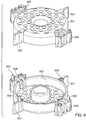
- FIGS. 6 to 8 Now further optional features of the preformed insulation structure and the arrangement of the preformed insulation structure are explained in a housing.
- the preformed insulation structure as well as the first and second windings correspond to those in the FIGS. 2 to 5 shown elements.
- those based on FIGS. 6 to 8 described optional Characteristics are also used with other insulation structures (for example, one-piece or multi-part insulation structures).
- FIG. 6 a preformed insulation structure consisting of two shells 204, 205 is shown, which corresponds to the preformed insulation structure of FIG. 4 equivalent.
- the insulation structure is provided with the first and second windings 202, 203.
- FIG. 6 a corresponding housing 301 configured to receive the first and second windings 202, 203 and the transformer core 201 and the preformed insulation structure from the first and second shells 204, 205.
- the housing forms a sufficiently dimensioned interior.
- the housing 301 has optional brackets 304 to which the ends of the first and second windings 202, 203 are attached and which provide an interface of the transformer to the outside world.
- brackets 304 are disposed on protrusions 303 attached to an outer side 305 of the housing 301.
- FIG. 6 an example in which the brackets 304 and protrusions 303 are disposed at opposite positions on the housing 301.
- the ends of the first and second windings can be led out through passages in the housing 301 from the interior of the housing 301 and fixed there.
- the bare (ie, the insulation sheath of the wire ends removed) wires are wrapped around the brackets 304.
- other forms of brackets 304 are possible.
- the housing may be disposed within a circuit (for example, on a printed circuit board).
- the housing has eyelets 302 for screws or similar fastening means.
- Both the preformed isolation structure and the housing 301 may optionally include other features that facilitate or facilitate the positioning and fixation of the preformed isolation structure in the housing 301. These features are now based on FIG. 7 explained in detail.
- the preformed isolation structures may include one or more protrusions 207 disposed on outer walls of the preformed isolation structure.
- the first and second shells 204, 205 each have two projections 207a, 207b.
- the housing 301 has corresponding indentations 307a, 307b.
- the indentations 307a, 307b are formed by four free-standing wall elements 309a-309d, which extend from the top of the housing 301 into the interior of the housing 301.
- the indentations 307a, 307b and the protrusions 207a, 207b are arranged and dimensioned such that the preformed insulation structure with the first and second windings 202, 203 and the transformer core 201 can be inserted into the housing 301 such that the protrusions 207a, 207b in FIG the indentations 307a, 307b engage.
- the position of the preformed insulation structure - and thus also the first and second windings and the transformer core - in the plane of the FIG. 7 be set within the housing 301.
- the distance of the preformed insulation structure from the circumferential side wall of the housing 301 and a rotation angle of the preformed insulation structure can be determined.
- the former may be advantageous because the distance of the preformed insulation structure and thus also the first and second windings of the circumferential side wall of the housing 301 co-determines the dielectric strength of the transformer to the outside world.
- the projections 207a, 207b and the indentations 307a, 307b it is possible to achieve a substantially equidistant spacing of the preformed insulation structure and thus also of the first and second windings of the circumferential side wall of the housing 301. This can prevent the formation of weak points where dielectric breakdown can occur.
- the transformer can be made more compact since no or less additional insulating material must be provided to prevent dielectric breakdowns.
- the adjustment of the angle of rotation of the preformed insulation structure in the housing 301 may facilitate the assembly of the transformer.
- the wire ends of the first and second windings come to rest where they can be guided through the wall of the housing 301 to the outside world.
- the functions of positioning the preformed isolation structure within the housing 301 may also be used with other positioning structures than those in FIG FIG. 7 shown protrusions 207a, 207b and indentations 307a, 307b can be achieved.
- the distance of the preformed insulation structure from the circumferential side wall of the housing 301 can be adjusted in this example only by projections of the preformed insulation structure, which can contact the peripheral side wall of the housing 301 directly.
- indentations can be introduced directly into the circumferential lateral wall of the housing 301, which act in the same way as the indentations 307a, 307b.
- the design of the projections is variable.
- two opposite projections 207a, 207b are provided.
- the number and / or position of the projections may also be different.
- a projection that may be clamped in a corresponding indentation may be provided for positioning the preformed isolation structure.
- other elements of the preformed insulation structure can also serve for positioning within the housing 301.
- the wire retainers may be configured to define (at least partially) a distance of the preformed insulation structure from the circumferential side wall of the housing 301.
- the projections 207a, 207b and indentations 307a, 307b in FIG. 7 can set the position and angle of rotation of the preformed isolation structure in a first plane.
- the housing 301 has a plurality of protrusions 308. These projections 308 define the spacing of the preformed insulation structure from a bottom surface of the housing 301 (the term "bottom” refers to those in FIG FIG. 7 shown arrangement and is relative, a surface normal of the bottom is perpendicular to the first plane just defined).
- the preformed isolation structure eg, first and / or second shells 204, 205) may include one or more protrusions to space the preformed isolation structure from the underside of the housing.
- FIG. 8 is a perspective view of the in FIGS. 6 and 7 to see parts of a transformer shown in the assembled state.
- the preformed isolation structure 222 is optionally associated with FIG. 7 Positioning aids described - positioned within the housing 301.
- a potting compound can be filled into the housing to increase the dielectric strength of the transformer and to encapsulate the windings and the transformer core from the outside world.
- the preformed insulation structure has a plurality of holes 206. These may be arranged such that the interior formed by the preformed insulation structure 222 can be filled through the holes 206 without formation of voids.
- the holes 206 are also in FIGS. 2 to 7 to see.
- the first and second shells 204, 205 each have a plurality of holes.
- a potting compound is described as an exemplary insulating substance.
- other isolation substances may be used in conjunction with the preformed isolation structures described herein.
- an insulating liquid for example, an insulating oil
- an insulating gas may be used.
- the first and second shells 204, 205 may be sized to provide additional holes when the first and second shells 204, 205 are assembled. For example, in FIG. 10 to see that elongate air gaps 910 are formed when the first and second shells 204, 205 are assembled. Due to the elongated air gaps, a flow behavior of the potting compound during filling of the first and the second shell 204, 205 can be improved.
- holes 206 arranged on top 210 and bottom 211 of first and second shells 204, 205 are round. However, this geometry is not mandatory. Also, the holes need not necessarily be disposed on two opposite sides of the preformed isolation structure (eg, top 210 and bottom 211). Thus, the top and bottom of the preformed insulation structure may comprise only spoke-shaped arranged webs, so that form segment-shaped holes. In other examples, the holes may be rectangular, hexagonal or oval his. It merely has to be ensured that the size, shape and position of the holes are selected such that the potting compound can penetrate through the holes into the interior of the preformed insulation structure.
- the resulting opening may already be sufficient for filling the interior of the preformed insulation structure with potting compound.
- a reliable filling of the interior of the preformed insulation structure with potting compound can be ensured.
- the preformed insulation structures are made by an injection molding process.
- the preformed insulation structures can be made particularly inexpensive.
- the preformed isolation device can only consist of two parts.
- One or more positioning structures for positioning the preformed insulation structure within a housing, wire holders, and connectors for connecting various portions of the preformed insulation structure may be made integral with the portions for spacing the first and second windings.
- a first injection molded part 901 and a second injection molded part 902 include.
- Each of the first and second injection-molded parts 901, 902 has integral positioning structures 907 (also as projections) designated), wire holder 908 and connectors 909 on. Not only the special in FIG.
- the positioning structures 907 for positioning the preformed isolation structure within a housing, the wire retainers, and the connectors for connecting various portions of the isolation structure may be made integral with only one of a plurality of portions of the preformed isolation structure.
- the insulation structure consists of two identically shaped shells. In this way, the production cost of the preformed insulation structure can be further reduced as the number of injection molds required is reduced (or the number of molds for other molding processes).
- the housings for the transformers described herein can be manufactured by the same manufacturing method as the preformed insulation structures.
- the housing and all parts of a one- or multi-piece preformed insulation structure can be manufactured by means of an injection molding process.
- the housing and the parts of the preformed insulation structure may be made of the same material as the housing.
- the production costs for a transformer containing these parts can be further reduced.
- one or more portions of the preformed isolation structure may be connected to the housing. Then, these one or more parts can be produced simultaneously with the case (for example, as an injection molded part).
- the preformed insulation structure exists of two shells and one of the shells is connected to the housing and made with the housing as an injection molded part.
- the second shell may be another injection molded part or also be connected to the housing.
- the parts of the preformed insulation structure eg, the shells FIGS. 2 to 10 ) a thermoplastic (made of a thermoplastic).
- the parts of the preformed insulation structure can also comprise a duroplastic (consist of a duroplastic).
- the housings in which the preformed insulation structures are embedded can be made of the same materials as the preformed insulation structures.
- the preformed insulation structures may comprise (consist of a material) a material having a dielectric constant of 1 to 10 at 0 to 10 MHz.
- the transformer may have a rectangular or oval cross-section.
- a two- or multi-part transformer core structure can also be implemented with a correspondingly shaped insulation structure.
- the geometry of the receptacle formed by the preformed insulation structure may also vary.
- the preformed insulation structure defines a closed, cylindrical surface having a passage for winding the second winding.
- the preformed insulation structure may be different Define closed surfaces.
- the preformed isolation structure defines an annular torus.
- the interior of the preformed isolation structure may also be open to one or more sides.
- the transformer includes a third or third and further windings.
- Figures 11a and 11b show ways of how to further wind in terms of FIGS. 2 to 10 presented devices can be arranged.
- a plurality of windings 1103a, 1103b may be wound along the circumference of a transformer core 1101.
- the in Figures 11a and 11b Windings shown both directly on the transformer core, as well as on the preformed insulation structures of FIGS. 2 to 10 be wrapped.
- FIG. 11a For example, two windings are each wound on only one segment of the transformer core 1101 (for example, such that each winding extends less than 175 ° deg along the transformer core).
- Figures 12a and 12b Another example of such a three winding arrangement is shown. In such an arrangement, the breakdown strength between a first winding wound directly on the transformer core and the further (for example two further) windings wound around a preformed insulation structure may still be determined (co-) by the preformed insulation structure. In contrast, the windings wound around the predetermined insulation structure may be insulated from each other by their spacing along the transformer core.
- FIG. 11b Another arrangement of two windings 1103a, 1103b is shown.
- the two windings are intertwined around the entire transformer core 1101 (they extend more than 300 degrees around the transformer core). This arrangement of turns can reduce stray inductance.
- a third winding or coils may be interlaced around the entire transformer core 1101.
- FIGS. 12a and 12b show another example of a preformed insulation structure and its arrangement with multiple windings in a transformer. As well as in FIGS. 2 to 10 is in Figures 12a and 12b one out see two shells existing preformed insulation structure.
- FIG. 12a FIG. 12 illustrates a schematic plan view of a first shell 1204 of the preformed isolation structure having a plurality of holes.
- additional structures wire holder, connection structures and / or positioning structures
- the upper and lower shells 1204, 1205 have a winding aid 1210, with the aid of which a plurality of windings can be positioned along the circumference of the shells 1204, 1205.
- this winding aid 1210 is designed as two intersecting struts.
- four segments are defined along the perimeter of the first and second shells 1204, 1205.
- FIG. 12b is a partial sectional view (only the upper shell is cut away, the windings and the transformer core is shown in a plan view) to see how different windings around two of the in FIG. 12a shown shells are arranged around.
- two windings 1202a, 1202b are similar to those in FIG FIG. 11b shown wrapped directly around the transformer core 1201.
- the transformer core with the two windings 1202a, 1202b is of the first and second shells 1204, 1205 (the first shell is in FIG FIG. 12b not to be seen) enclosed.
- Each winding 1203a-1203c extends in a segment of the preformed insulation structure that is less than 90 ° deg of the circumference of the preformed insulation structure.
- the winding aid 1210 limits each of the windings 1203a-1203c to a predetermined segment. Although in FIG. 12b If three windings 1203a-1203c are shown, the winding aid can also be used for two or more than three windings.
- the two 1202a, 1202b windings wound directly on the transformer core 1201 may be windings of the transformer, and the three windings 1203a-1203c may be secondary windings of the transformer.
- the segmented winding of the three windings 1203a-1203c can be used to make the three windings with each other have a high dielectric strength - in addition to the high dielectric strength of each of these winding against the wound directly on the transformer core windings 1202a, 1202b.
- the one or more windings wound directly on the transformer core would be primary windings of the transformer and the one or more windings wound on the preformed insulation structure would be secondary windings of the transformer.
- the one or more windings wound directly on the transformer core may be secondary windings of the transformer and the one or more windings wound on the preformed insulation structure may be primary windings of the transformer.
- the three windings may provide windings 1203a-1203c with different voltage levels. This does not just apply to the example of Figures 12a and 12b But in general for discussed herein transformers with three or more windings.
- FIGS. 2 to 12 Several preformed isolation structures have been described in which two shells enclose a transformer core.
- the first shell forms an upper surface of the preformed insulation structure and the second shell forms a lower surface.
- the "top” and “bottom” are herein separated by a plane in which or parallel to which the magnetic flux passes through the transformer core during operation of the transformer core.
- this plane cuts the transformer core to form two parts with annular cut surfaces (see, for example, FIG Figures 11a and 11b where the plane lies in the drawing plane).
- two parts of a preformed insulation structure enclose right and left parts of the transformer core.
- the "right side” and “left side” are herein separated by a second plane perpendicular to which the magnetic flux passes through the transformer core during operation of the transformer core (ie, this plane is perpendicular to the plane defined in the last paragraph).
- this second plane cuts the transformer core so that two parts with two circular cut surfaces arise (or a sectional area with oval cross-section or cross-section in the form of an eight).
- the Figures 13a and 13b show a further non-inventive example of a preformed insulation structure and its arrangement with multiple windings in a transformer.
- the preformed insulation structure shown is in three parts: a transformer core wound with one or more first windings (for example, as in FIG Figures 11a and 11b shown) is enclosed by the two half-shells 1304a, 1304b.
- a tubular center part 1314 is inserted into a through hole of the half shells 1304a, 1304b and the transformer core.
- the transformer core and the windings are thus completely enclosed by the preformed insulation structure.
- Other second windings can now be wound around the shells through the insulation tube. These further second windings are correspondingly spaced apart from the inner first windings by the three-part insulation structure.
- FIG. 12 illustrates a schematic plan view of the two equal-sized shells 1304a, 1304b, which are each configured to have right and left sides of a transformer core (not in FIG. 13b shown).
- this preformed isolation structure of this example may include a tubular centerpiece 1314.
- the assembling of the transformer in this example first comprises placing the transformer core with a first winding in one of the shells 1304a, 1304b. Then, the second shell 1304a, 1304b is connected to the first shell 1304a, 1304b to enclose the transformer core.
- the tubular center part 1314 may be performed before or after joining the shells 1304a, 1304b. Subsequently, a second winding can be wound on the preformed insulation structure.
- FIG. 13b shows a schematic side view of one of the two half-shells 1304a.
- the half-shell 1304a has a plurality of holes 106, through which a casting compound (or other insulating substance) can reach the interior of a receptacle formed by the first half-shell 1304a and the second half-shell 1304b.
- the half-shells 1304a, 1304b may also have other features described herein, such as positioning structures or wire holders and feedthroughs for wires.
- the parts enclose the transformer core symmetrically.
- each part of the preformed isolation structure encloses an equal proportion of the transformer core.
- this arrangement is not mandatory.
- one of two (or more) parts of a two or more part preformed isolation structure may enclose a smaller portion of the transformer core than the others.
- the lower shell 205 include the entire side wall.
- the upper shell 204 is then a lid that can be placed or put on the under shell 205.
- FIG. 14 a further two-piece preformed insulation structure is shown.
- a first part 1404 of this preformed insulation structure covers the top (the definition of the term "top” is found above), a first part of the outside side surface, and a part of the bottom side (the definition of the term “bottom side” is given above) of a cylindrical one Admission.
- a second part 1405 of this preformed insulation structure covers the remaining part of the outer side surface and the remaining part of the lower side.
- both parts 1204, 1205 thus surround the entire surface of the cylindrical receptacle (with the exception of a central recess).
- shells are in FIG. 14 Parts shown not symmetrical (that is, they cover different sized parts of the surface of the cylindrical receptacle).
- a preformed insulation structure having an interior for receiving a transformer core and a portion of a first winding and an outer space in which the second winding is wound defined.
- the transformer structures described herein are not limited thereto.
- a second preformed isolation structure may enclose a first preformed isolation structure.
- the first isolation structure in this example encloses a transformer core having one or more first windings.
- One or more second windings are wound around the first insulation structure.
- the one or more second windings wound around the first insulation structure are in turn of the second preformed one Enclosed isolation structure. These are wound one or more third windings.
- the two preformed insulation structures are thus arranged like the shells of an onion. In this arrangement with two preformed insulation structures, the above-described two or more part preformed insulation structures can be used.
- the transformer core may be enclosed by a preformed isolation structure.
- One or more first windings may be wound on this first preformed insulation structure.
- the core with the first insulation structure and the one or more first windings may in turn be enclosed by a second insulation structure, on which one or more second windings are wound.
- Another exemplary method includes the steps of providing a transformer core, wrapping a first wire around a transformer core to form a first winding, disposing a preformed insulation structure such that the preformed insulation structure encloses and winds at least a portion of the first winding and the transformer core a second wire around the preformed insulation structure to form a second winding. Then the arrangement of windings, transformer core and preformed insulation structure can be introduced into a housing.
- the housing can be filled with a potting compound.
- the pouring of the housing can be performed by a die-casting method.
- the pouring of the housing under vacuum at a residual pressure of 500 mbar or less
- the formation of air or gas bubbles in the potting compound can be suppressed.
- the preformed insulation structure comprises wire holders
- the first and second wires may be fixed at a location in one of the wire holders.
- the winding process (whether by hand or by machine) can be simplified because resetting movements of the wires can be reduced.
Landscapes
- Engineering & Computer Science (AREA)
- Power Engineering (AREA)
- Microelectronics & Electronic Packaging (AREA)
- Insulating Of Coils (AREA)
- Manufacturing Cores, Coils, And Magnets (AREA)
- Coils Of Transformers For General Uses (AREA)
- Coils Or Transformers For Communication (AREA)
Priority Applications (4)
| Application Number | Priority Date | Filing Date | Title |
|---|---|---|---|
| EP14155017.8A EP2908320B1 (de) | 2014-02-13 | 2014-02-13 | Transformator mit Isolationsstruktur und Verfahren zur Herstellung eines Transformators mit Isolationsstruktur |
| US14/616,411 US9773608B2 (en) | 2014-02-13 | 2015-02-06 | Insulation structure for transformer, method for insulating a transformer, and transformer comprising insulation structure |
| JP2015024838A JP6606330B2 (ja) | 2014-02-13 | 2015-02-11 | 変圧器のための絶縁構造体、変圧器の絶縁方法及び絶縁構造体を備える変圧器 |
| CN201510079842.5A CN104851572B (zh) | 2014-02-13 | 2015-02-13 | 用于变压器的隔离结构、隔离变压器的方法、以及包括隔离结构的变压器 |
Applications Claiming Priority (1)
| Application Number | Priority Date | Filing Date | Title |
|---|---|---|---|
| EP14155017.8A EP2908320B1 (de) | 2014-02-13 | 2014-02-13 | Transformator mit Isolationsstruktur und Verfahren zur Herstellung eines Transformators mit Isolationsstruktur |
Publications (2)
| Publication Number | Publication Date |
|---|---|
| EP2908320A1 EP2908320A1 (de) | 2015-08-19 |
| EP2908320B1 true EP2908320B1 (de) | 2019-04-10 |
Family
ID=50073059
Family Applications (1)
| Application Number | Title | Priority Date | Filing Date |
|---|---|---|---|
| EP14155017.8A Active EP2908320B1 (de) | 2014-02-13 | 2014-02-13 | Transformator mit Isolationsstruktur und Verfahren zur Herstellung eines Transformators mit Isolationsstruktur |
Country Status (4)
| Country | Link |
|---|---|
| US (1) | US9773608B2 (enExample) |
| EP (1) | EP2908320B1 (enExample) |
| JP (1) | JP6606330B2 (enExample) |
| CN (1) | CN104851572B (enExample) |
Families Citing this family (27)
| Publication number | Priority date | Publication date | Assignee | Title |
|---|---|---|---|---|
| JP6525676B2 (ja) * | 2015-03-31 | 2019-06-05 | ヴィオニア日信ブレーキシステムジャパン株式会社 | ブレーキ制御装置用チョークコイル |
| US10056184B2 (en) * | 2015-10-20 | 2018-08-21 | Madison Daily | Segmented core cap system for toroidal transformers |
| US20190057807A1 (en) * | 2016-02-29 | 2019-02-21 | Bolymedia Holdings Co. Ltd. | Electromagnetic induction device and method for manufacturing same |
| DE102016209613A1 (de) * | 2016-06-01 | 2017-12-07 | Würth Elektronik eiSos Gmbh & Co. KG | Montagesatz für eine Drossel und Drossel |
| DE102016110579A1 (de) | 2016-06-08 | 2017-12-14 | Epcos Ag | Induktives Bauteil |
| CN109417849B (zh) * | 2016-07-12 | 2021-08-17 | Abb电网瑞士股份公司 | 电流分离装置 |
| WO2018126223A1 (en) * | 2016-12-30 | 2018-07-05 | Eagle Harbor Technologies, Inc. | High voltage inductive adder |
| US10504647B2 (en) * | 2017-04-03 | 2019-12-10 | Bel Fuse (Macao Commercial Off | Magnetic transformer having increased bandwidth for high speed data communications |
| US10892082B2 (en) * | 2017-12-12 | 2021-01-12 | Hamilton Sundstrand Corporation | Systems and methods for cooling toroidal magnetics |
| JP6936130B2 (ja) * | 2017-12-13 | 2021-09-15 | 株式会社タムラ製作所 | コイル部品 |
| DE112019001341T5 (de) * | 2018-03-15 | 2020-11-26 | Mitsubishi Electric Corporation | Drosselspule |
| DE102018106449A1 (de) * | 2018-03-20 | 2019-09-26 | Vacuumschmelze Gmbh & Co. Kg | Magnetische Baugruppe |
| US11605496B2 (en) | 2018-04-09 | 2023-03-14 | Abb Schweiz Ag | Foil wound magnetic assemblies with thermally conductive tape and methods of assembling same |
| DE102018111468A1 (de) * | 2018-05-14 | 2019-11-14 | Schaffner International AG | Drossel mit Stromschienenwindungen |
| EP3803921B1 (en) | 2018-05-31 | 2025-02-26 | Power Integrations, Inc. | Housing for ferrite beads and other pass-through electrical filter components |
| GB2576316B (en) * | 2018-08-13 | 2021-03-03 | Murata Manufacturing Co | Isolation core for power converter |
| JP6823627B2 (ja) | 2018-09-05 | 2021-02-03 | 矢崎総業株式会社 | 電線の配索構造およびワイヤハーネス |
| CN110060846A (zh) * | 2019-06-03 | 2019-07-26 | 南通国轩新能源科技有限公司 | 一种新型变压器铁芯 |
| CN112309694A (zh) * | 2019-07-31 | 2021-02-02 | 台达电子企业管理(上海)有限公司 | 变压器及其制造方法 |
| CN112309677B (zh) * | 2019-07-31 | 2023-06-06 | 台达电子企业管理(上海)有限公司 | 变压器结构及其制造方法 |
| WO2021257360A1 (en) * | 2020-06-19 | 2021-12-23 | Murata Manufacturing Co., Ltd. | Enclosure for isolating transformer core from windings |
| CN111785483B (zh) * | 2020-08-10 | 2024-08-30 | 江苏瑞恩电气有限公司 | 高绝缘耐热等级高过载的节能变压器 |
| CN112863832B (zh) * | 2021-01-23 | 2023-03-24 | 上海硕大电子科技有限公司 | 一种电磁阀用电磁线圈及制造工艺 |
| DE102021205047A1 (de) * | 2021-05-18 | 2022-11-24 | Robert Bosch Gesellschaft mit beschränkter Haftung | Elektrische Anordnung mit Drosselspule |
| WO2024020351A1 (en) * | 2022-07-19 | 2024-01-25 | CorePower Magnetics, Inc. | Inductor for low and medium voltage application |
| CN115116739B (zh) * | 2022-08-12 | 2023-06-16 | 杭州裕正电子有限公司 | 一种新能源汽车变压器组件及扩展方法 |
| CN116246869A (zh) * | 2023-03-14 | 2023-06-09 | 上海纳宇电气有限公司 | 一种电流互感器一次多圈引线新结构及其生产工艺 |
Family Cites Families (22)
| Publication number | Priority date | Publication date | Assignee | Title |
|---|---|---|---|---|
| US3480897A (en) * | 1967-09-05 | 1969-11-25 | Gen Electric | Adjustable sliding brush transformer and method of producing same |
| DE2549379C2 (de) * | 1975-11-04 | 1977-10-27 | Siemens AG, 1000 Berlin und 8000 München | Ringkern-Transformator |
| DE3110427A1 (de) * | 1981-03-18 | 1982-11-25 | Sachße, Brigitte, 8500 Nürnberg | Ringkern-transformator-uebertrager-drossel |
| US4779812A (en) * | 1982-01-06 | 1988-10-25 | Kuhlman Corporation | Toroidal electrical transformer and method of producing same |
| JPH0521850Y2 (enExample) * | 1987-06-16 | 1993-06-04 | ||
| JPH01140809U (enExample) * | 1988-03-22 | 1989-09-27 | ||
| JPH028108U (enExample) * | 1988-06-28 | 1990-01-19 | ||
| JPH0729813U (ja) * | 1993-10-29 | 1995-06-02 | 松下電工株式会社 | トロイダル状トランス |
| CN2195789Y (zh) * | 1994-05-06 | 1995-04-26 | 特电电子工业股份有限公司 | 具有真空冲压成型式绝缘层结构的电源变压器 |
| JPH1174135A (ja) * | 1997-08-27 | 1999-03-16 | Hitachi Ferrite Electronics Ltd | 高圧トランス |
| JPH11312611A (ja) * | 1998-04-27 | 1999-11-09 | Mankun O | トロイダルトランス |
| JP3239214B2 (ja) * | 1999-08-09 | 2001-12-17 | 株式会社エス・エッチ・ティ | コイル装置 |
| US6753749B1 (en) * | 2003-06-05 | 2004-06-22 | Artesyn Technologies, Inc. | Toroidal transformer enclosure |
| JP2007142341A (ja) * | 2005-11-22 | 2007-06-07 | Otowa Denki Kogyo Kk | 耐雷強化型低圧用絶縁変圧器の放熱構造 |
| JP4794999B2 (ja) * | 2005-11-22 | 2011-10-19 | 音羽電機工業株式会社 | 耐雷強化型低圧用絶縁変圧器 |
| CN102013308A (zh) * | 2009-09-04 | 2011-04-13 | 奥斯兰姆有限公司 | 电子变压器 |
| JP2011119605A (ja) * | 2009-12-07 | 2011-06-16 | Kyocera Chemical Corp | 大型モールドコイル含浸用樹脂組成物、及びそれを用いた大型モールドコイル |
| CN201918248U (zh) * | 2011-01-10 | 2011-08-03 | 宁夏银利电器制造有限公司 | 漏感值可控的环形变压器 |
| US8299879B2 (en) * | 2011-02-10 | 2012-10-30 | Leco Corporation | Transformer assembly using an internal load and method for forming same |
| CN102522191A (zh) * | 2011-12-30 | 2012-06-27 | 江苏利通电子有限公司 | 一种环形隔离变压器 |
| CN102969135B (zh) * | 2012-11-21 | 2016-01-20 | 王奉瑾 | 环形变压器 |
| CN203312012U (zh) * | 2013-06-13 | 2013-11-27 | 重庆正博仪器工业有限公司 | 内外绕组式隔离变压器 |
-
2014
- 2014-02-13 EP EP14155017.8A patent/EP2908320B1/de active Active
-
2015
- 2015-02-06 US US14/616,411 patent/US9773608B2/en active Active
- 2015-02-11 JP JP2015024838A patent/JP6606330B2/ja active Active
- 2015-02-13 CN CN201510079842.5A patent/CN104851572B/zh active Active
Non-Patent Citations (1)
| Title |
|---|
| None * |
Also Published As
| Publication number | Publication date |
|---|---|
| JP6606330B2 (ja) | 2019-11-13 |
| US20150228401A1 (en) | 2015-08-13 |
| EP2908320A1 (de) | 2015-08-19 |
| CN104851572A (zh) | 2015-08-19 |
| JP2015154081A (ja) | 2015-08-24 |
| US9773608B2 (en) | 2017-09-26 |
| CN104851572B (zh) | 2018-12-07 |
Similar Documents
| Publication | Publication Date | Title |
|---|---|---|
| EP2908320B1 (de) | Transformator mit Isolationsstruktur und Verfahren zur Herstellung eines Transformators mit Isolationsstruktur | |
| DE69904045T2 (de) | Spulenkörper für transformator | |
| DE2632886A1 (de) | Vorrichtung zum befestigen von zuleitungen an einer elektrischen einrichtung, wie transformatoren | |
| DE112007002320T5 (de) | Transformator des Blechtyps und Entladungsleuchtenbeleuchtungsvorrichtung | |
| DE102015106186A1 (de) | Elektromotor | |
| DE102018113899B4 (de) | Drossel mit Eisenkernen und Spulen | |
| EP0175069B1 (de) | Verfahren zur Herstellung eines induktiven Bauelements mit einem bewickelten Ringbandkern | |
| EP1774545B1 (de) | Halterung für eine elektrische komponente | |
| WO2016071098A2 (de) | Induktives bauelement | |
| DE102013001916A1 (de) | Elektromotor | |
| DE3324078C2 (enExample) | ||
| EP2395518B1 (de) | Gehäuse zum Aufbau von Luftspalt-getrennten magnetischen Kernsäulen für induktive Bauteile | |
| WO2017036715A1 (de) | Felgenelektrode und wicklungsanordnung eines messwandlers | |
| EP2248139B1 (de) | Drosselanordnung mit einer eine erste und eine zweite teilwicklung aufweisenden spule | |
| EP2523198B1 (de) | Transformator mit geblechter Wicklung | |
| DE4239818C2 (de) | Bewickelter Ringkern | |
| DE102004008961B4 (de) | Spulenkörper für geschlossenen magnetischen Kern und daraus hergestellte Entstördrossel | |
| DE10005029A1 (de) | Drossel | |
| DE3113743C2 (enExample) | ||
| DE602004012416T2 (de) | Isolieranordnung für elektrische Bauelemente | |
| DE2651734A1 (de) | Spulenkoerper | |
| DE102011005165B4 (de) | Spule mit einer Wicklung, die eine Durchmesserreduzierung aufweist, Stromsensor mit einer solchen Spule und Verfahren zur Herstellung einer solchen Spule und eines solchen Stromsensors | |
| DE112023005882T5 (de) | Neue Wicklungsstruktur und Herstellungsverfahren hierfür | |
| DE3022070A1 (de) | Schirmkoerper fuer bewickelte kernschenkel von transformatoren, drosselspulen u.dgl. | |
| DE2624819A1 (de) | Wicklungstraeger fuer einen uebertragerspulenkoerper |
Legal Events
| Date | Code | Title | Description |
|---|---|---|---|
| PUAI | Public reference made under article 153(3) epc to a published international application that has entered the european phase |
Free format text: ORIGINAL CODE: 0009012 |
|
| 17P | Request for examination filed |
Effective date: 20140213 |
|
| AK | Designated contracting states |
Kind code of ref document: A1 Designated state(s): AL AT BE BG CH CY CZ DE DK EE ES FI FR GB GR HR HU IE IS IT LI LT LU LV MC MK MT NL NO PL PT RO RS SE SI SK SM TR |
|
| AX | Request for extension of the european patent |
Extension state: BA ME |
|
| GRAP | Despatch of communication of intention to grant a patent |
Free format text: ORIGINAL CODE: EPIDOSNIGR1 |
|
| STAA | Information on the status of an ep patent application or granted ep patent |
Free format text: STATUS: GRANT OF PATENT IS INTENDED |
|
| INTG | Intention to grant announced |
Effective date: 20180926 |
|
| GRAS | Grant fee paid |
Free format text: ORIGINAL CODE: EPIDOSNIGR3 |
|
| RAP1 | Party data changed (applicant data changed or rights of an application transferred) |
Owner name: POWER INTEGRATIONS SWITZERLAND GMBH |
|
| GRAA | (expected) grant |
Free format text: ORIGINAL CODE: 0009210 |
|
| STAA | Information on the status of an ep patent application or granted ep patent |
Free format text: STATUS: THE PATENT HAS BEEN GRANTED |
|
| AK | Designated contracting states |
Kind code of ref document: B1 Designated state(s): AL AT BE BG CH CY CZ DE DK EE ES FI FR GB GR HR HU IE IS IT LI LT LU LV MC MK MT NL NO PL PT RO RS SE SI SK SM TR |
|
| REG | Reference to a national code |
Ref country code: GB Ref legal event code: FG4D Free format text: NOT ENGLISH |
|
| REG | Reference to a national code |
Ref country code: CH Ref legal event code: EP Ref country code: AT Ref legal event code: REF Ref document number: 1119791 Country of ref document: AT Kind code of ref document: T Effective date: 20190415 |
|
| REG | Reference to a national code |
Ref country code: IE Ref legal event code: FG4D Free format text: LANGUAGE OF EP DOCUMENT: GERMAN |
|
| REG | Reference to a national code |
Ref country code: DE Ref legal event code: R096 Ref document number: 502014011353 Country of ref document: DE |
|
| REG | Reference to a national code |
Ref country code: NL Ref legal event code: MP Effective date: 20190410 |
|
| REG | Reference to a national code |
Ref country code: LT Ref legal event code: MG4D |
|
| PG25 | Lapsed in a contracting state [announced via postgrant information from national office to epo] |
Ref country code: NL Free format text: LAPSE BECAUSE OF FAILURE TO SUBMIT A TRANSLATION OF THE DESCRIPTION OR TO PAY THE FEE WITHIN THE PRESCRIBED TIME-LIMIT Effective date: 20190410 |
|
| PG25 | Lapsed in a contracting state [announced via postgrant information from national office to epo] |
Ref country code: AL Free format text: LAPSE BECAUSE OF FAILURE TO SUBMIT A TRANSLATION OF THE DESCRIPTION OR TO PAY THE FEE WITHIN THE PRESCRIBED TIME-LIMIT Effective date: 20190410 Ref country code: ES Free format text: LAPSE BECAUSE OF FAILURE TO SUBMIT A TRANSLATION OF THE DESCRIPTION OR TO PAY THE FEE WITHIN THE PRESCRIBED TIME-LIMIT Effective date: 20190410 Ref country code: LT Free format text: LAPSE BECAUSE OF FAILURE TO SUBMIT A TRANSLATION OF THE DESCRIPTION OR TO PAY THE FEE WITHIN THE PRESCRIBED TIME-LIMIT Effective date: 20190410 Ref country code: HR Free format text: LAPSE BECAUSE OF FAILURE TO SUBMIT A TRANSLATION OF THE DESCRIPTION OR TO PAY THE FEE WITHIN THE PRESCRIBED TIME-LIMIT Effective date: 20190410 Ref country code: SE Free format text: LAPSE BECAUSE OF FAILURE TO SUBMIT A TRANSLATION OF THE DESCRIPTION OR TO PAY THE FEE WITHIN THE PRESCRIBED TIME-LIMIT Effective date: 20190410 Ref country code: PT Free format text: LAPSE BECAUSE OF FAILURE TO SUBMIT A TRANSLATION OF THE DESCRIPTION OR TO PAY THE FEE WITHIN THE PRESCRIBED TIME-LIMIT Effective date: 20190910 Ref country code: NO Free format text: LAPSE BECAUSE OF FAILURE TO SUBMIT A TRANSLATION OF THE DESCRIPTION OR TO PAY THE FEE WITHIN THE PRESCRIBED TIME-LIMIT Effective date: 20190710 Ref country code: FI Free format text: LAPSE BECAUSE OF FAILURE TO SUBMIT A TRANSLATION OF THE DESCRIPTION OR TO PAY THE FEE WITHIN THE PRESCRIBED TIME-LIMIT Effective date: 20190410 |
|
| PG25 | Lapsed in a contracting state [announced via postgrant information from national office to epo] |
Ref country code: LV Free format text: LAPSE BECAUSE OF FAILURE TO SUBMIT A TRANSLATION OF THE DESCRIPTION OR TO PAY THE FEE WITHIN THE PRESCRIBED TIME-LIMIT Effective date: 20190410 Ref country code: RS Free format text: LAPSE BECAUSE OF FAILURE TO SUBMIT A TRANSLATION OF THE DESCRIPTION OR TO PAY THE FEE WITHIN THE PRESCRIBED TIME-LIMIT Effective date: 20190410 Ref country code: PL Free format text: LAPSE BECAUSE OF FAILURE TO SUBMIT A TRANSLATION OF THE DESCRIPTION OR TO PAY THE FEE WITHIN THE PRESCRIBED TIME-LIMIT Effective date: 20190410 Ref country code: GR Free format text: LAPSE BECAUSE OF FAILURE TO SUBMIT A TRANSLATION OF THE DESCRIPTION OR TO PAY THE FEE WITHIN THE PRESCRIBED TIME-LIMIT Effective date: 20190711 Ref country code: BG Free format text: LAPSE BECAUSE OF FAILURE TO SUBMIT A TRANSLATION OF THE DESCRIPTION OR TO PAY THE FEE WITHIN THE PRESCRIBED TIME-LIMIT Effective date: 20190710 |
|
| PG25 | Lapsed in a contracting state [announced via postgrant information from national office to epo] |
Ref country code: IS Free format text: LAPSE BECAUSE OF FAILURE TO SUBMIT A TRANSLATION OF THE DESCRIPTION OR TO PAY THE FEE WITHIN THE PRESCRIBED TIME-LIMIT Effective date: 20190810 |
|
| REG | Reference to a national code |
Ref country code: DE Ref legal event code: R097 Ref document number: 502014011353 Country of ref document: DE |
|
| PG25 | Lapsed in a contracting state [announced via postgrant information from national office to epo] |
Ref country code: CZ Free format text: LAPSE BECAUSE OF FAILURE TO SUBMIT A TRANSLATION OF THE DESCRIPTION OR TO PAY THE FEE WITHIN THE PRESCRIBED TIME-LIMIT Effective date: 20190410 Ref country code: SK Free format text: LAPSE BECAUSE OF FAILURE TO SUBMIT A TRANSLATION OF THE DESCRIPTION OR TO PAY THE FEE WITHIN THE PRESCRIBED TIME-LIMIT Effective date: 20190410 Ref country code: RO Free format text: LAPSE BECAUSE OF FAILURE TO SUBMIT A TRANSLATION OF THE DESCRIPTION OR TO PAY THE FEE WITHIN THE PRESCRIBED TIME-LIMIT Effective date: 20190410 Ref country code: DK Free format text: LAPSE BECAUSE OF FAILURE TO SUBMIT A TRANSLATION OF THE DESCRIPTION OR TO PAY THE FEE WITHIN THE PRESCRIBED TIME-LIMIT Effective date: 20190410 Ref country code: EE Free format text: LAPSE BECAUSE OF FAILURE TO SUBMIT A TRANSLATION OF THE DESCRIPTION OR TO PAY THE FEE WITHIN THE PRESCRIBED TIME-LIMIT Effective date: 20190410 |
|
| PLBE | No opposition filed within time limit |
Free format text: ORIGINAL CODE: 0009261 |
|
| STAA | Information on the status of an ep patent application or granted ep patent |
Free format text: STATUS: NO OPPOSITION FILED WITHIN TIME LIMIT |
|
| PG25 | Lapsed in a contracting state [announced via postgrant information from national office to epo] |
Ref country code: SM Free format text: LAPSE BECAUSE OF FAILURE TO SUBMIT A TRANSLATION OF THE DESCRIPTION OR TO PAY THE FEE WITHIN THE PRESCRIBED TIME-LIMIT Effective date: 20190410 Ref country code: IT Free format text: LAPSE BECAUSE OF FAILURE TO SUBMIT A TRANSLATION OF THE DESCRIPTION OR TO PAY THE FEE WITHIN THE PRESCRIBED TIME-LIMIT Effective date: 20190410 |
|
| 26N | No opposition filed |
Effective date: 20200113 |
|
| PG25 | Lapsed in a contracting state [announced via postgrant information from national office to epo] |
Ref country code: TR Free format text: LAPSE BECAUSE OF FAILURE TO SUBMIT A TRANSLATION OF THE DESCRIPTION OR TO PAY THE FEE WITHIN THE PRESCRIBED TIME-LIMIT Effective date: 20190410 |
|
| PG25 | Lapsed in a contracting state [announced via postgrant information from national office to epo] |
Ref country code: SI Free format text: LAPSE BECAUSE OF FAILURE TO SUBMIT A TRANSLATION OF THE DESCRIPTION OR TO PAY THE FEE WITHIN THE PRESCRIBED TIME-LIMIT Effective date: 20190410 |
|
| GBPC | Gb: european patent ceased through non-payment of renewal fee |
Effective date: 20200213 |
|
| REG | Reference to a national code |
Ref country code: BE Ref legal event code: MM Effective date: 20200229 |
|
| PG25 | Lapsed in a contracting state [announced via postgrant information from national office to epo] |
Ref country code: MC Free format text: LAPSE BECAUSE OF FAILURE TO SUBMIT A TRANSLATION OF THE DESCRIPTION OR TO PAY THE FEE WITHIN THE PRESCRIBED TIME-LIMIT Effective date: 20190410 Ref country code: LU Free format text: LAPSE BECAUSE OF NON-PAYMENT OF DUE FEES Effective date: 20200213 |
|
| PG25 | Lapsed in a contracting state [announced via postgrant information from national office to epo] |
Ref country code: GB Free format text: LAPSE BECAUSE OF NON-PAYMENT OF DUE FEES Effective date: 20200213 Ref country code: IE Free format text: LAPSE BECAUSE OF NON-PAYMENT OF DUE FEES Effective date: 20200213 |
|
| PG25 | Lapsed in a contracting state [announced via postgrant information from national office to epo] |
Ref country code: BE Free format text: LAPSE BECAUSE OF NON-PAYMENT OF DUE FEES Effective date: 20200229 |
|
| REG | Reference to a national code |
Ref country code: AT Ref legal event code: MM01 Ref document number: 1119791 Country of ref document: AT Kind code of ref document: T Effective date: 20200213 |
|
| PG25 | Lapsed in a contracting state [announced via postgrant information from national office to epo] |
Ref country code: AT Free format text: LAPSE BECAUSE OF NON-PAYMENT OF DUE FEES Effective date: 20200213 |
|
| PG25 | Lapsed in a contracting state [announced via postgrant information from national office to epo] |
Ref country code: FR Free format text: LAPSE BECAUSE OF NON-PAYMENT OF DUE FEES Effective date: 20200302 |
|
| PG25 | Lapsed in a contracting state [announced via postgrant information from national office to epo] |
Ref country code: MT Free format text: LAPSE BECAUSE OF FAILURE TO SUBMIT A TRANSLATION OF THE DESCRIPTION OR TO PAY THE FEE WITHIN THE PRESCRIBED TIME-LIMIT Effective date: 20190410 Ref country code: CY Free format text: LAPSE BECAUSE OF FAILURE TO SUBMIT A TRANSLATION OF THE DESCRIPTION OR TO PAY THE FEE WITHIN THE PRESCRIBED TIME-LIMIT Effective date: 20190410 |
|
| PG25 | Lapsed in a contracting state [announced via postgrant information from national office to epo] |
Ref country code: MK Free format text: LAPSE BECAUSE OF FAILURE TO SUBMIT A TRANSLATION OF THE DESCRIPTION OR TO PAY THE FEE WITHIN THE PRESCRIBED TIME-LIMIT Effective date: 20190410 |
|
| P01 | Opt-out of the competence of the unified patent court (upc) registered |
Effective date: 20230502 |
|
| PGFP | Annual fee paid to national office [announced via postgrant information from national office to epo] |
Ref country code: DE Payment date: 20250227 Year of fee payment: 12 |
|
| PGFP | Annual fee paid to national office [announced via postgrant information from national office to epo] |
Ref country code: CH Payment date: 20250304 Year of fee payment: 12 |