EP2898997A2 - Robotersystem, Saughand mit Zuschneider und Verfahren zur Herstellung eines Produkts mit einem Werkstück - Google Patents
Robotersystem, Saughand mit Zuschneider und Verfahren zur Herstellung eines Produkts mit einem Werkstück Download PDFInfo
- Publication number
- EP2898997A2 EP2898997A2 EP15150749.8A EP15150749A EP2898997A2 EP 2898997 A2 EP2898997 A2 EP 2898997A2 EP 15150749 A EP15150749 A EP 15150749A EP 2898997 A2 EP2898997 A2 EP 2898997A2
- Authority
- EP
- European Patent Office
- Prior art keywords
- workpiece
- cutter
- targeted
- suction
- suction hand
- Prior art date
- Legal status (The legal status is an assumption and is not a legal conclusion. Google has not performed a legal analysis and makes no representation as to the accuracy of the status listed.)
- Withdrawn
Links
Images



Classifications
-
- B—PERFORMING OPERATIONS; TRANSPORTING
- B25—HAND TOOLS; PORTABLE POWER-DRIVEN TOOLS; MANIPULATORS
- B25J—MANIPULATORS; CHAMBERS PROVIDED WITH MANIPULATION DEVICES
- B25J11/00—Manipulators not otherwise provided for
- B25J11/005—Manipulators for mechanical processing tasks
- B25J11/0055—Cutting
-
- G—PHYSICS
- G05—CONTROLLING; REGULATING
- G05B—CONTROL OR REGULATING SYSTEMS IN GENERAL; FUNCTIONAL ELEMENTS OF SUCH SYSTEMS; MONITORING OR TESTING ARRANGEMENTS FOR SUCH SYSTEMS OR ELEMENTS
- G05B19/00—Program-control systems
- G05B19/02—Program-control systems electric
- G05B19/18—Numerical control [NC], i.e. automatically operating machines, in particular machine tools, e.g. in a manufacturing environment, so as to execute positioning, movement or co-ordinated operations by means of program data in numerical form
- G05B19/182—Numerical control [NC], i.e. automatically operating machines, in particular machine tools, e.g. in a manufacturing environment, so as to execute positioning, movement or co-ordinated operations by means of program data in numerical form characterised by the machine tool function, e.g. thread cutting, cam making, tool direction control
-
- B—PERFORMING OPERATIONS; TRANSPORTING
- B25—HAND TOOLS; PORTABLE POWER-DRIVEN TOOLS; MANIPULATORS
- B25J—MANIPULATORS; CHAMBERS PROVIDED WITH MANIPULATION DEVICES
- B25J15/00—Gripping heads and other end effectors
- B25J15/0019—End effectors other than grippers
-
- B—PERFORMING OPERATIONS; TRANSPORTING
- B25—HAND TOOLS; PORTABLE POWER-DRIVEN TOOLS; MANIPULATORS
- B25J—MANIPULATORS; CHAMBERS PROVIDED WITH MANIPULATION DEVICES
- B25J15/00—Gripping heads and other end effectors
- B25J15/0052—Gripping heads and other end effectors multiple gripper units or multiple end effectors
- B25J15/0066—Gripping heads and other end effectors multiple gripper units or multiple end effectors with different types of end effectors, e.g. gripper and welding gun
-
- B—PERFORMING OPERATIONS; TRANSPORTING
- B25—HAND TOOLS; PORTABLE POWER-DRIVEN TOOLS; MANIPULATORS
- B25J—MANIPULATORS; CHAMBERS PROVIDED WITH MANIPULATION DEVICES
- B25J15/00—Gripping heads and other end effectors
- B25J15/06—Gripping heads and other end effectors with vacuum or magnetic holding means
- B25J15/0616—Gripping heads and other end effectors with vacuum or magnetic holding means with vacuum
-
- B—PERFORMING OPERATIONS; TRANSPORTING
- B25—HAND TOOLS; PORTABLE POWER-DRIVEN TOOLS; MANIPULATORS
- B25J—MANIPULATORS; CHAMBERS PROVIDED WITH MANIPULATION DEVICES
- B25J9/00—Program-controlled manipulators
- B25J9/16—Program controls
-
- B—PERFORMING OPERATIONS; TRANSPORTING
- B26—HAND CUTTING TOOLS; CUTTING; SEVERING
- B26D—CUTTING; DETAILS COMMON TO MACHINES FOR PERFORATING, PUNCHING, CUTTING-OUT, STAMPING-OUT OR SEVERING
- B26D1/00—Cutting through work characterised by the nature or movement of the cutting member or particular materials not otherwise provided for; Apparatus or machines therefor; Cutting members therefor
- B26D1/01—Cutting through work characterised by the nature or movement of the cutting member or particular materials not otherwise provided for; Apparatus or machines therefor; Cutting members therefor involving a cutting member which does not travel with the work
- B26D1/44—Cutting through work characterised by the nature or movement of the cutting member or particular materials not otherwise provided for; Apparatus or machines therefor; Cutting members therefor involving a cutting member which does not travel with the work having a cup or like cutting member
-
- B—PERFORMING OPERATIONS; TRANSPORTING
- B26—HAND CUTTING TOOLS; CUTTING; SEVERING
- B26D—CUTTING; DETAILS COMMON TO MACHINES FOR PERFORATING, PUNCHING, CUTTING-OUT, STAMPING-OUT OR SEVERING
- B26D1/00—Cutting through work characterised by the nature or movement of the cutting member or particular materials not otherwise provided for; Apparatus or machines therefor; Cutting members therefor
- B26D1/01—Cutting through work characterised by the nature or movement of the cutting member or particular materials not otherwise provided for; Apparatus or machines therefor; Cutting members therefor involving a cutting member which does not travel with the work
- B26D1/45—Cutting through work characterised by the nature or movement of the cutting member or particular materials not otherwise provided for; Apparatus or machines therefor; Cutting members therefor involving a cutting member which does not travel with the work having a cutting member the movement of which is not covered by any preceding group
-
- B—PERFORMING OPERATIONS; TRANSPORTING
- B26—HAND CUTTING TOOLS; CUTTING; SEVERING
- B26D—CUTTING; DETAILS COMMON TO MACHINES FOR PERFORATING, PUNCHING, CUTTING-OUT, STAMPING-OUT OR SEVERING
- B26D7/00—Details of apparatus for cutting, cutting-out, stamping-out, punching, perforating, or severing by means other than cutting
- B26D7/01—Means for holding or positioning work
- B26D7/018—Holding the work by suction
-
- B—PERFORMING OPERATIONS; TRANSPORTING
- B26—HAND CUTTING TOOLS; CUTTING; SEVERING
- B26F—PERFORATING; PUNCHING; CUTTING-OUT; STAMPING-OUT; SEVERING BY MEANS OTHER THAN CUTTING
- B26F1/00—Perforating; Punching; Cutting-out; Stamping-out; Apparatus therefor
- B26F1/38—Cutting-out; Stamping-out
-
- B—PERFORMING OPERATIONS; TRANSPORTING
- B26—HAND CUTTING TOOLS; CUTTING; SEVERING
- B26F—PERFORATING; PUNCHING; CUTTING-OUT; STAMPING-OUT; SEVERING BY MEANS OTHER THAN CUTTING
- B26F1/00—Perforating; Punching; Cutting-out; Stamping-out; Apparatus therefor
- B26F1/38—Cutting-out; Stamping-out
- B26F1/44—Cutters therefor; Dies therefor
-
- B—PERFORMING OPERATIONS; TRANSPORTING
- B26—HAND CUTTING TOOLS; CUTTING; SEVERING
- B26F—PERFORATING; PUNCHING; CUTTING-OUT; STAMPING-OUT; SEVERING BY MEANS OTHER THAN CUTTING
- B26F3/00—Severing by means other than cutting; Apparatus therefor
- B26F3/002—Precutting and tensioning or breaking
-
- B—PERFORMING OPERATIONS; TRANSPORTING
- B26—HAND CUTTING TOOLS; CUTTING; SEVERING
- B26D—CUTTING; DETAILS COMMON TO MACHINES FOR PERFORATING, PUNCHING, CUTTING-OUT, STAMPING-OUT OR SEVERING
- B26D1/00—Cutting through work characterised by the nature or movement of the cutting member or particular materials not otherwise provided for; Apparatus or machines therefor; Cutting members therefor
- B26D1/0006—Cutting members therefor
- B26D2001/006—Cutting members therefor the cutting blade having a special shape, e.g. a special outline, serrations
-
- B—PERFORMING OPERATIONS; TRANSPORTING
- B26—HAND CUTTING TOOLS; CUTTING; SEVERING
- B26F—PERFORATING; PUNCHING; CUTTING-OUT; STAMPING-OUT; SEVERING BY MEANS OTHER THAN CUTTING
- B26F1/00—Perforating; Punching; Cutting-out; Stamping-out; Apparatus therefor
- B26F1/38—Cutting-out; Stamping-out
- B26F1/44—Cutters therefor; Dies therefor
- B26F2001/4481—Cutters therefor; Dies therefor having special lateral or edge outlines or special surface shapes, e.g. apertures
-
- G—PHYSICS
- G05—CONTROLLING; REGULATING
- G05B—CONTROL OR REGULATING SYSTEMS IN GENERAL; FUNCTIONAL ELEMENTS OF SUCH SYSTEMS; MONITORING OR TESTING ARRANGEMENTS FOR SUCH SYSTEMS OR ELEMENTS
- G05B2219/00—Program-control systems
- G05B2219/30—Nc systems
- G05B2219/35—Nc in input of data, input till input file format
- G05B2219/35165—Automatic cutter selection
-
- G—PHYSICS
- G05—CONTROLLING; REGULATING
- G05B—CONTROL OR REGULATING SYSTEMS IN GENERAL; FUNCTIONAL ELEMENTS OF SUCH SYSTEMS; MONITORING OR TESTING ARRANGEMENTS FOR SUCH SYSTEMS OR ELEMENTS
- G05B2219/00—Program-control systems
- G05B2219/30—Nc systems
- G05B2219/45—Nc applications
- G05B2219/45068—Cutting robot
-
- Y—GENERAL TAGGING OF NEW TECHNOLOGICAL DEVELOPMENTS; GENERAL TAGGING OF CROSS-SECTIONAL TECHNOLOGIES SPANNING OVER SEVERAL SECTIONS OF THE IPC; TECHNICAL SUBJECTS COVERED BY FORMER USPC CROSS-REFERENCE ART COLLECTIONS [XRACs] AND DIGESTS
- Y10—TECHNICAL SUBJECTS COVERED BY FORMER USPC
- Y10S—TECHNICAL SUBJECTS COVERED BY FORMER USPC CROSS-REFERENCE ART COLLECTIONS [XRACs] AND DIGESTS
- Y10S901/00—Robots
- Y10S901/30—End effector
- Y10S901/40—Vacuum or mangetic
Definitions
- the present invention relates to a robot system, a suction hand, and a method for producing a product including a workpiece.
- Japanese Unexamined Patent Application Publication No. 2011-177848 discloses a transfer robot with a robot hand to which a suction hand is mounted so as to suck a to-be-transferred object. From above the to-be-transferred object, the transfer robot moves the suction hand of the robot hand close to the to-be-transferred object, causes the suction hand to suck the to-be-transferred object, and moves the robot hand upward. In this manner, the transfer robot transfers the to-be-transferred object.
- the to-be-transferred object (also referred to as workpiece) may have a flexible sheet shape.
- the transfer robot as recited in Japanese Unexamined Patent Application Publication No. 2011-177848 uses the suction hand to suck a targeted to-be-transferred object from among the to-be-transferred objects, the suction hand may suck the to-be-transferred object with an untargeted to-be-transferred object attached to the targeted to-be-transferred object.
- the present disclosure has been made in view of the above-described circumstances, and it is an object of the present disclosure to provide a robot system, a suction hand, and a method for producing a product including a workpiece that eliminate or minimize the attachment of an untargeted workpiece to a targeted workpiece when the targeted workpiece is held by the suction hand.
- a robot system includes a suction hand, a robot, and a cutter.
- the suction hand includes a holder configured to hold a flexible sheet-shaped workpiece.
- the suction hand is mountable to the robot.
- the cutter is disposed in a vicinity of a circumferential edge portion of the holder so as to separate a targeted workpiece from an untargeted workpiece.
- the robot system includes a cutter in the vicinity of a circumferential edge portion of the holder of the suction hand.
- the cutter separates a targeted workpiece from an untargeted workpiece. Since the cutter separates the targeted workpiece from the untargeted workpiece, the attachment of the untargeted workpiece to the targeted workpiece when the targeted workpiece is held by the suction hand is eliminated or minimized.
- a suction hand is applicable to a robot system.
- the robot system includes the suction hand, a robot, and a cutter.
- the suction hand includes a holder configured to hold a flexible sheet-shaped workpiece.
- the suction hand is mountable to the robot.
- the cutter is disposed in a vicinity of a circumferential edge portion of the holder so as to separate a targeted workpiece from an untargeted workpiece.
- the suction hand includes a cutter in the vicinity of a circumferential edge portion of the holder of the suction hand.
- the cutter separates a targeted workpiece from an untargeted workpiece. Since the cutter separates the targeted workpiece from the untargeted workpiece, the suction hand eliminates or minimizes the attachment of the untargeted workpiece to the targeted workpiece when the targeted workpiece is held by the suction hand.
- a method for producing a product including a workpiece.
- the method includes pressing a cutter against a targeted flexible sheet-shaped workpiece so as to separate the targeted flexible sheet-shaped workpiece from an untargeted flexible sheet-shaped workpiece.
- the cutter is disposed in a vicinity of a circumferential edge portion of a holder of a suction hand.
- the holder is configured to hold the targeted flexible sheet-shaped workpiece.
- the separated targeted workpiece is held using the holder.
- the method for producing a product including a workpiece includes pressing a cutter against a targeted flexible sheet-shaped workpiece so as to separate the targeted flexible sheet-shaped workpiece from an untargeted flexible sheet-shaped workpiece, the cutter being disposed in the vicinity of a circumferential edge portion of the holder of the suction hand, the holder being configured to hold the targeted flexible sheet-shaped workpiece. Since the cutter separates the targeted workpiece from the untargeted workpiece, the method for producing a product including a workpiece eliminates or minimizes the attachment of the untargeted workpiece to the targeted workpiece when the targeted workpiece is held by the suction hand.
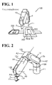
- the robot system 100 includes a robot 1 and a suction hand 2.
- the robot 1 is a vertical multi-articular robot, and the suction hand 2 is mounted to the robot 1 to hold a flexible sheet-shaped workpiece 200.
- a cutter 24, described later, of the suction hand 2 cuts a largest workpiece 201 to separate an individual workpiece 200 (that is, a targeted workpiece 200 is separated from the largest workpiece 201). Then, the separated workpiece 200 is placed on (attached to) a product 203, which is disposed in the vicinity of a workpiece support 202.
- the robot 1 includes a base 11 and an arm 12.
- the arm 12 is mounted on the base 11, and has six degrees of freedom.
- the arm 12 has a plurality of arm structures.
- An arm structure 12a is coupled to the base 11 in a rotatable manner about a rotation axis A1, which is perpendicular to the installation surface of the robot 1.
- An arm structure 12b is coupled to the arm structure 12a in a rotatable manner about a rotation axis A2, which is perpendicular to the rotation axis A1.
- An arm structure 12c is coupled to the arm structure 12b in a rotatable manner about a rotation axis A3, which is parallel to the rotation axis A2.
- An arm structure 12d is coupled to the arm structure 12c in a rotatable manner about a rotation axis A4, which is perpendicular to the rotation axis A3.
- An arm structure 12e is coupled to the arm structure 12d in a rotatable manner about a rotation axis A5, which is perpendicular to the rotation axis A4.
- An arm structure 12f is coupled to the arm structure 12e in a rotatable manner about a rotation axis A6, which is perpendicular to the rotation axis A5.
- "parallel” and “perpendicular”, as used herein, are not only intended to mean precisely “parallel” and “perpendicular”, respectively, but also intended more broadly to encompass slight differences from being “parallel” or “perpendicular”.
- Each of the rotation axes A1 to A6 is equipped with a servo motor (joint).
- Each servo motor includes an encoder to detect the rotation position of the servo motor.
- each servo motor is coupled to a robot controller 3 (see FIG. 6 ) so that each servo motor operates based on a command from the robot controller 3.
- the suction hand 2 includes a mounting portion 21.
- the mounting portion 21 is mounted to the arm structure 12f of the robot 1.
- the mounting portion 21 has an approximately U shape.
- the suction hand 2 includes a box-shaped suction device 22.
- the suction device 22 is mounted to the mounting portion 21, and includes a hollow space 22a (see FIG. 5 ).
- a pipe 23 (see FIG. 3 ) is coupled in the hollow space 22a of the suction device 22 to take in or discharge air.
- the suction device 22 of the suction hand 2 includes a suction surface 22b.
- the suction surface 22b faces downward (in the Z2 direction) for the workpiece 200 to be sucked onto the suction surface 22b.
- the suction surface 22b has a flat shape.
- a cutter 24 is disposed to separate the targeted workpiece 200 from the remaining workpiece (the largest workpiece 201, see FIG. 1 ). Specifically, the cutter 24 cuts the targeted workpiece 200 from the largest workpiece 201 (see FIG. 1 ), thus separating the targeted workpiece 200 from the largest workpiece 201.
- the cutter 24 is made of aluminum, SUS (Stainless steel), or another material. It is noted that the suction surface 22b is an example of the "holder” and the "holding surface”.
- the cutter 24 protrudes from the suction surface 22b of the suction device 22 toward the workpiece 200 (in the Z2 direction). Specifically, the cutter 24 extends in a direction (Z direction) perpendicular to the suction surface 22b, and protrudes from a vicinity of the circumferential edge portion of the suction surface 22b toward the workpiece 200.
- the length, L, by which the cutter 24 protrudes from the suction surface 22b is approximately equal to the thickness, t1 , of the workpiece 200.
- the length L (height by which the cutter 24 protrudes) by which the cutter 24 protrudes from the suction surface 22b is approximately constant throughout the entire area of the cutter 24.
- the suction surface 22b has an approximately rectangular shape in a plan view, and the cutter 24 is disposed along at least two intersecting sides of the approximately rectangular shape of the suction surface 22b.
- the suction surface 22b has an approximately square shape in a plan view
- the cutter 24 has a frame shape (walled shape) along the four sides (sides 221, 222, 223, and 224) of the approximately square shape of the suction surface 22b.
- the frame shape of the cutter 24 is disposed in the vicinity of the circumferential edge portion of the suction surface 22b, and has an approximately identical shape to the outer shape of the separated workpiece 200 in a plan view. In other words, the workpiece 200 is cut off with an approximately square shape that approximately matches the inner circumference surface of the frame shape of the cutter 24 in a plan view.
- the cutter 24 includes a surface (inner side surface) 24a at the side of the suction surface 22b.
- the surface 24a has a flat shape perpendicular to a placement surface 202a, on which the workpiece 200 is placed.
- the surface 24a of the cutter 24, which is at the side of the suction surface 22b extends in the direction (Z direction) perpendicular to the suction surface 22b.
- the cutter 24 also has an outer surface 24b. At the side of the suction surface 22b (Z1 direction side), the outer surface 24b extends in the direction (Z direction) perpendicular to the placement surface 202a.
- the outer surface 24b is inclined relative to the direction (Z direction) perpendicular to the placement surface 202a.
- the distal end side of the cutter 24 has such a tapered shape that the thickness, t 2, of the cutter 24 gradually decreases toward the distal end (Z2 direction side) of the cutter 24.
- holes 22c are disposed on the suction surface 22b of the suction hand 2.
- the workpiece 200 is sucked onto the suction surface 22b.
- the workpiece 200 is released off the suction surface 22b.
- a plurality of holes 22c (nine holes 22c in the first embodiment) are disposed.
- the plurality of holes 22c are arranged in a matrix.
- each hole 22c is a through hole communicating with the hollow space 22a of the suction device 22. As illustrated in FIGs.
- the suction surface 22b with the holes 22c is arranged in a space 25, which is defined by the frame shape of the cutter 24.
- the robot system 100 includes the robot 1 and a robot controller 3.
- the robot controller 3 controls the overall operations of the robot system 100.
- the robot controller 3 includes a control section 31 and a memory 32.
- the workpiece 200 one largest workpiece 201 is placed on the placement surface 202a in advance.
- the control section 31 moves the arm 12 while turning the suction hand 2 relative to the placement surface 202a so as to press the cutter 24 of the suction hand 2 against the workpiece 200 and cut off the workpiece 200 (separate the targeted workpiece 200 from the largest workpiece 201), and controls the suction hand 2 to suck and hold the workpiece 200.
- the cutter 24 of the suction hand 2 is moved to a vicinity of the workpiece 200 (workpiece 201).
- the cutter 24 of the suction hand 2 is pressed against the workpiece 200.
- the cutter 24 (axis line C of the cutter 24) is inclined toward the end side (X2 direction side) of the workpiece 200 by a predetermined angle ⁇ relative to a direction perpendicular to the surface of the workpiece 200 (workpiece 201).
- the edge of the cutter 24 at the X2 direction side contacts the end of the workpiece 200 at the X2 direction side.
- the suction hand 2 is rotated in the R direction relative to the placement surface 202a, on which the workpiece 200 (the largest workpiece 201) is placed in advance.
- the cutter 24 axis line C of the cutter 24
- the targeted workpiece 200 is cut off the largest workpiece 201.
- the targeted workpiece 200 is separated from the largest workpiece 201. While in FIGs. 7 to 10 a corner of the largest workpiece 201 is cut to obtain the workpiece 200, any other portion of the largest workpiece 201 may be cut to obtain the workpiece 201. For example, it is possible to cut the workpiece 200 off the center portion of the largest workpiece 201.
- the cutter 24 is provided in a vicinity of the circumferential edge portion of the suction surface 22b of the suction hand 2 to separate the targeted workpiece 200 from the other workpieces 200, as described above.
- the targeted workpiece 200 is separated by the cutter 24 from the other workpieces 200. This eliminates or minimizes the attachment of the other workpieces 200 to the targeted workpiece 200 while the targeted workpiece 200 is being held by the suction hand 2.
- the cutter 24 protrudes from the suction surface 22b toward the workpiece 200, as described above. This ensures that the workpiece 200 held by the suction surface 22b is more easily separated from the other workpieces 200 using the cutter 24.
- the cutter 24 has a frame shape along the four sides (sides 221, 222, 223, and 224) of the approximately rectangular shape of the suction surface 22b, as described above. This ensures that the targeted workpiece 200 is cut off the largest workpiece 201 with a shape matching the approximately rectangular shape of the suction surface 22b.
- the holes 22c are provided on the suction surface 22b to take in air so as to suck the workpiece 200, and the suction surface 22b with the holes 22c is disposed in the space defined by the frame shape of the cutter 24, as described above. This ensures that the suction surface 22b and the workpiece 200 are surrounded by the frame shape of the cutter 24. This, in turn, eliminates or minimizes removal of excessive air from the gap between the suction surface 22b and the workpiece 200 (the sucked surface of the workpiece 200). This, as a result, increases the suction force for the workpiece 200.
- the frame shape of the cutter 24 is disposed in a vicinity of the circumferential edge portion of the suction surface 22b and, the cutter 24 has an approximately identical shape to the outer shape of the separated workpiece 200, as described above. This ensures that the workpiece 200 is readily cut off in a desired shape.
- the length L by which the cutter 24 protrudes from the suction surface 22b is approximately equal to the thickness t1 of the workpiece 200, as described above. If the length L by which the cutter 24 protrudes from the suction surface 22b is smaller than the thickness of the workpiece 200 ( L ⁇ t1 ), the lower end of the cutter 24 fails to reach the placement surface 202a, on which the workpiece 200 is placed. This may make it difficult to cut the targeted workpiece 200 off the largest workpiece 201.
- the length L by which the cutter 24 protrudes from the suction surface 22b is larger than the thickness of the workpiece 200 ( L > t1 ), even though the lower end of the cutter 24 reaches the placement surface 202a, on which the workpiece 200 is placed, a gap occurs between the upper surface of the workpiece 200 and the suction surface 22b. This may make it difficult to suck the workpiece 200 onto the suction surface 22b.
- the length L by which the cutter 24 protrudes from the suction surface 22b is approximately equal to the thickness t1 of the workpiece 200. This ensures reliability in cutting off the workpiece 200 and reliability in holding the workpiece 200.
- the surface 24a of the cutter 24 at the side of the suction surface 22b has a flat shape perpendicular to the placement surface 202a, on which the workpiece 200 is placed, as described above. This makes it easier to make the side surfaces of the targeted workpiece 200 perpendicular to the placement surface 202a.
- the holes 22c are provided on the suction surface 22b of the suction hand 2, as described above. Through the holes 22c, air is taken in so as to suck the workpiece 200, and the air is discharged so as to release the workpiece 200 off the suction surface 22b. By taking in (discharging) air, the workpiece 200 is readily sucked (released).
- the control section 31 is provided to control the robot 1. Specifically, the control section 31 moves the arm 12 of the robot 1 while turning the suction hand 2 relative to the placement surface 202a, on which the workpiece 200 is placed in advance, so as to press the cutter 24 of the suction hand 2 against the workpiece 200 and separate the workpiece 200, and controls the suction hand 2 to suck and hold the separated workpiece 200, as described above.
- the suction hand 2 (cutter 24) makes a vertically downward movement to cut off the workpiece 200, the cutter 24 may crush the workpiece 200 (the cutter 24 may deform the workpiece 200).
- the arm 12 of the robot 1 moves while the suction hand 2 (cutter 24) is turned relative to the placement surface 202a, on which the workpiece 200 is placed in advance, so as to press the cutter 24 of the suction hand 2 against the workpiece 200 and separate the workpiece 200.
- This ensures that the workpiece 200 is gradually cut off in such a manner that the cutting starts from a corner of the workpiece 200.
- This ensures effectiveness in cutting the workpiece 200 in a desired shape while eliminating or minimizing deformation of the workpiece 200.
- the cutter has a frame shape along the four sides of the approximately square shape of the suction surface.
- the cutter is along two intersecting sides among the four sides of the approximately square shape of the suction surface.
- a cutter 41 of the suction hand 4 is disposed along two sides (sides 221 and 222) among the four sides (sides 221, 222, 223, and 224) of the approximately square shape of the suction surface 22b.
- the suction hand 4 according to the second embodiment is otherwise similar to the suction hand 4 according to the first embodiment.
- the targeted workpiece 200 is indicated by dotted lines in FIG. 14 . That is, in the second embodiment, the workpiece 200 is cut off a corner (at the X2 direction side and at the Y2 direction side) of a largest workpiece 201. This ensures that the workpiece 200 is cut in an approximately square shape, even though the cutter 41 of the suction hand 4 is disposed along two sides (sides 221 and 222) of the approximately square shape of the suction surface 22b.
- the cutter 41 includes a portion 41a at the Y1 direction side and a portion 41b at the X1 direction side.
- the targeted workpiece 200 includes a side 200a at the Y1 direction side and a side 200b at the X1 direction side.
- the portion 41a of the cutter 41 is positioned along the side 200a of the targeted workpiece 200, and the portion 41b of the cutter 41 is positioned along the side 200b of the targeted workpiece 200.
- the cutter 41 is turned in the R direction to cut off the workpiece 200.
- the operations in the second embodiment are otherwise similar to the operations in the first embodiment.
- the suction surface 22b has an approximately square shape (approximately rectangular shape) in a plan view, and the cutter 41 is disposed along two intersecting sides of the approximately square shape of the suction surface 22b, as described above. This simplifies the configuration of the suction hand 4, as compared with an exemplary case where the cutter 41 is disposed along the four sides of the approximately square shape of the suction surface 22b.
- the arm of the robot may have other than six degrees of freedom (equal to or less than five degrees of freedom, or equal to or more than seven degrees of freedom).
- the cutter of the suction hand has been described as being disposed along the four sides (or two sides) of the suction surface, the cutter of the suction hand may be disposed outside (or inside) the sides of the suction surface insofar as the cutter of the suction hand is disposed in a vicinity of the suction surface.
- the suction surface of the suction hand has been described as being flat, the suction surface may have any other shape insofar as the shape of the suction surface matches the surface shape of the targeted workpiece.
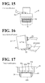
- a suction surface 51 of a suction hand 5 may have other than an approximately square shape (examples including, but not limited to, an approximately rectangular shape) as illustrated in a first modification of FIG. 15 .
- a frame shaped cutter 52 also has an approximately rectangular shape in a plan view.
- the suction surface 51 is an example of the "holder” and the "holding surface”.
- the suction hand moves upward after the targeted workpiece has been cut off. In this manner, the targeted workpiece is held (moved) (see FIG. 11 ). In this respect, as illustrated in FIG. 16 , the remaining untargeted workpiece 201 may be sucked to the outer surface of the cutter even though the targeted workpiece is cut off and separated from the remaining untargeted workpiece 201. In this case, in a second modification illustrated in FIG. 16 , after the targeted workpiece has been cut off, the suction hand 5 may be turned in the S direction, which is opposite to the R direction, to remove the remaining untargeted workpiece 201 sucked to the outer side of the cutter 52 from the cutter 52. Then, the targeted workpiece may be moved.
- the targeted workpiece has been described as being directly sucked to the suction surface of the suction hand.
- a reticulated member 61 may be disposed on the suction surface 22b of a suction hand 6. This reduces the force of taking in air through the holes 22c and eliminates or minimizes damage to the targeted workpiece 200 associated with contact with the holes 22c.
- a plurality of holes have been illustrated as being provided on the suction surface of the suction hand.
- a single comparatively large hole 72 may be provided on a suction surface 71 of a suction hand 7, and a porous film 73 may be provided on the surface of the hole 72. This ensures that the targeted workpiece (not illustrated in FIG. 18 ) is held using air taken in through the porous film 73.
- the porous film 73 has fine holes, and this eliminates or minimizes damage to the targeted workpiece caused by the holes of the porous film 73.
- the suction surface 71 is an example of the "holder” and the "holding surface”.
- a partition wall 82 may be provided in a space 81 of a suction hand 8 to take in (or discharge) air separately through a hole 83a and through a hole 83b.
- the hole 83b alone to take in air in the suction of a workpiece 204, which has a surface area smaller than the surface area of a suction surface 83c. That is, when the hole 83a is not involved in the suction of the workpiece 204, no air is taken in through the hole 83a. This eliminates or minimizes an increase in the amount of air to be taken in.
- the suction surface 83c is an example of the "holder" and the "holding surface”.
- the cutter has been described as being disposed along two sides or four sides of the approximately rectangular shape of the holding surface, the cutter may be disposed along one side or three sides of the approximately rectangular shape of the holding surface.
- the length L by which the cutter protrudes from the suction surface has been described as being approximately constant throughout the entire area of the cutter, the length L by which the cutter protrudes from the suction surface may vary depending on the parts of the area of the cutter.
- the cutter may have a cutter blade shape with a varying length L protruding from the suction surface.
- the inner side surface of the cutter has been described as being perpendicular to the placement surface on which the workpiece is placed, and the outer surface of the cutter has been described as being inclined relative to the placement surface on which the workpiece is placed (see FIG. 3 ).
- both the inner side surface and the outer surface of the cutter may be inclined relative to the placement surface.
- the cutter may have such a tapered shape that the inner side and the outer side of the cutter gradually come close to each other so as to implement a gradually decreasing thickness.
- both the inner side surface and the outer surface of the cutter may be perpendicular to the placement surface.
- the cutter may have a rectangular parallelepiped shape.
- the workpiece has been described as being sucked onto the suction surface by taking in air.
- the workpiece is made of a magnetic material, for example, it is possible to use magnetic force to attract the workpiece to the suction surface so as to hold the workpiece on the suction surface.
- the workpiece has been described as being sucked (or released) by air taken in (or discharged) through the holes.
- the workpiece is of a type that can be held (or released) without taking in (or discharging) air, no holes may be provided on the suction surface.
- the suction hand has been described as being turned relative to the placement surface on which the workpiece is placed so as to cut off (separate) the workpiece using the cutter. It is also possible to move the cutter vertically downward so as to cut off (separate) the workpiece using the cutter.
- one largest workpiece has been described as being cut by the cutter. It is also possible to cut the largest workpiece in advance into intermediate workpieces each having smallest workpieces attached to each other, and place the intermediate workpieces. Then, one of the intermediate workpieces may be cut with the cutter to separate one of the smallest workpieces from the rest of the smallest workpieces and hold the separated smallest workpiece.
- a cutter 91 of a suction hand 9 may have four parts 91a, 91b, 91c, and 91d mutually arranged at predetermined intervals in a plan view.
Landscapes
- Engineering & Computer Science (AREA)
- Mechanical Engineering (AREA)
- Life Sciences & Earth Sciences (AREA)
- Forests & Forestry (AREA)
- Robotics (AREA)
- Manufacturing & Machinery (AREA)
- Human Computer Interaction (AREA)
- Physics & Mathematics (AREA)
- General Physics & Mathematics (AREA)
- Automation & Control Theory (AREA)
- Manipulator (AREA)
- Details Of Cutting Devices (AREA)
- Control Of Cutting Processes (AREA)
Applications Claiming Priority (1)
| Application Number | Priority Date | Filing Date | Title |
|---|---|---|---|
| JP2014012685A JP2015139835A (ja) | 2014-01-27 | 2014-01-27 | ロボットシステム、吸着ハンドおよびワークを含む製品の製造方法 |
Publications (2)
| Publication Number | Publication Date |
|---|---|
| EP2898997A2 true EP2898997A2 (de) | 2015-07-29 |
| EP2898997A3 EP2898997A3 (de) | 2016-03-02 |
Family
ID=52396433
Family Applications (1)
| Application Number | Title | Priority Date | Filing Date |
|---|---|---|---|
| EP15150749.8A Withdrawn EP2898997A3 (de) | 2014-01-27 | 2015-01-12 | Robotersystem, Saughand mit Zuschneider und Verfahren zur Herstellung eines Produkts mit einem Werkstück |
Country Status (4)
| Country | Link |
|---|---|
| US (1) | US20150212508A1 (de) |
| EP (1) | EP2898997A3 (de) |
| JP (1) | JP2015139835A (de) |
| CN (1) | CN104802153A (de) |
Cited By (1)
| Publication number | Priority date | Publication date | Assignee | Title |
|---|---|---|---|---|
| WO2022223186A1 (en) * | 2021-04-19 | 2022-10-27 | Pip Innovations Bv | Tube-shaped knife |
Families Citing this family (8)
| Publication number | Priority date | Publication date | Assignee | Title |
|---|---|---|---|---|
| CN112352476A (zh) * | 2018-07-12 | 2021-02-09 | 迪睿合株式会社 | 拾取装置、安装装置、拾取方法、安装方法 |
| WO2020013333A1 (ja) * | 2018-07-12 | 2020-01-16 | デクセリアルズ株式会社 | ピックアップ装置、実装装置、ピックアップ方法、実装方法 |
| JP2020189341A (ja) * | 2019-05-17 | 2020-11-26 | 株式会社イシダ | 吸着搬送装置 |
| JP7279567B2 (ja) | 2019-07-30 | 2023-05-23 | 株式会社デンソーウェーブ | ロボット用吸着ハンド |
| CN110561458A (zh) * | 2019-09-27 | 2019-12-13 | 青岛新松机器人自动化有限公司 | 一种医用橡胶塞裁切系统 |
| EP4001137B1 (de) * | 2020-11-16 | 2025-03-19 | Uhlmann Pac-Systeme GmbH & Co. KG | Verfahren zum handhaben von bahnförmigem verpackungsmaterial |
| JP7773198B2 (ja) * | 2022-02-01 | 2025-11-19 | 株式会社片岡製作所 | 加工機 |
| CN114670219A (zh) * | 2022-04-26 | 2022-06-28 | 中国铁建高新装备股份有限公司 | 一种多功能机械臂式作业装置 |
Citations (1)
| Publication number | Priority date | Publication date | Assignee | Title |
|---|---|---|---|---|
| JP2011177848A (ja) | 2010-03-02 | 2011-09-15 | Ihi Corp | ロボットハンド及び搬送ロボット |
Family Cites Families (20)
| Publication number | Priority date | Publication date | Assignee | Title |
|---|---|---|---|---|
| JPH0715753Y2 (ja) * | 1989-02-23 | 1995-04-12 | 株式会社島津製作所 | 試験片作成装置 |
| JP2871119B2 (ja) * | 1991-01-30 | 1999-03-17 | 株式会社村田製作所 | セラミックグリーンシートの取扱方法および装置 |
| AT405497B (de) * | 1996-04-02 | 1999-08-25 | Gfm Gmbh | Verfahren zum ausschneiden von zuschnitten aus flachen, unregelmässigen werkstücken, insbesondere lederstücken |
| JP3584153B2 (ja) * | 1996-12-05 | 2004-11-04 | キヤノン株式会社 | 軟質部品の切断方法及び実装方法、軟質部品の切断装置及び実装装置 |
| JPH10209211A (ja) * | 1997-01-21 | 1998-08-07 | Sony Corp | フイルム供給装置及びその方法並びに実装装置及びその方法 |
| TW411309B (en) * | 1997-05-13 | 2000-11-11 | Taltec Systems Inc | Apparatus and method for automatically separating a silicon chip from a film strip, and apparatus and method of separating chip scale packages from a multi-layered film strip. |
| ITVI980185A1 (it) * | 1998-09-29 | 2000-03-29 | Antonio Riglietti | Macchina fustellatrice |
| JP2001089019A (ja) * | 1999-09-20 | 2001-04-03 | Canon Inc | シート部材の受け渡し方法及び装置及びシート置き台 |
| EP1162162B1 (de) * | 1999-12-16 | 2006-11-22 | Zuiko Corporation | Verfahren und vorrichtung zum fördern |
| US7011004B2 (en) * | 2001-07-06 | 2006-03-14 | Honda Giken Kogyo Kabushiki Kaisha | Trimming apparatus and method for fuel cell membrane/electrode coupling and transporting apparatus |
| JP2005507562A (ja) * | 2001-10-31 | 2005-03-17 | コーニンクレッカ フィリップス エレクトロニクス エヌ ヴィ | 有機集積回路を有するモジュールを製造する方法 |
| NL1019933C2 (nl) * | 2002-02-08 | 2003-08-11 | Fountain Tech Bv | Transportstans. |
| JP2004265495A (ja) * | 2003-02-28 | 2004-09-24 | Tdk Corp | 光記録媒体製造装置 |
| NZ571053A (en) * | 2006-03-21 | 2010-06-25 | Paul Robert Mccleary | Cutting apparatus such as an X-Y torch cutter inclined at an acute angle so as to take up less floor space |
| DE102007041423A1 (de) * | 2007-08-31 | 2009-03-05 | Abb Technology Ab | Roboterwerkzeug, Robotersystem und Verfahren zum Bearbeiten von Werkstücken |
| JP5492628B2 (ja) * | 2010-03-26 | 2014-05-14 | ユニ・チャーム株式会社 | 受け渡し装置 |
| CN201776797U (zh) * | 2010-08-09 | 2011-03-30 | 无锡吉兴汽车声学部件科技有限公司 | 一种用于聚氨酯硬泡材料取样的旋转刀具 |
| JP4927979B2 (ja) * | 2010-09-28 | 2012-05-09 | 株式会社新川 | 半導体ダイのピックアップ装置及びその装置を用いた半導体ダイのピックアップ方法 |
| TWM461531U (zh) * | 2013-05-03 | 2013-09-11 | Wei Kuang Automation Co Ltd | 膠膜裁切機之餘料去除裝置 |
| DE102013109857A1 (de) * | 2013-09-09 | 2015-03-12 | Dieffenbacher GmbH Maschinen- und Anlagenbau | Vorrichtung und Verfahren zum Zuschneiden und Handhaben eines flächenhaften Zuschnittes, insbesondere zur Herstellung von Bauteilen aus Faserverbundwerkstoff |
-
2014
- 2014-01-27 JP JP2014012685A patent/JP2015139835A/ja active Pending
- 2014-12-05 CN CN201410739986.4A patent/CN104802153A/zh active Pending
-
2015
- 2015-01-12 EP EP15150749.8A patent/EP2898997A3/de not_active Withdrawn
- 2015-01-26 US US14/604,755 patent/US20150212508A1/en not_active Abandoned
Patent Citations (1)
| Publication number | Priority date | Publication date | Assignee | Title |
|---|---|---|---|---|
| JP2011177848A (ja) | 2010-03-02 | 2011-09-15 | Ihi Corp | ロボットハンド及び搬送ロボット |
Cited By (1)
| Publication number | Priority date | Publication date | Assignee | Title |
|---|---|---|---|---|
| WO2022223186A1 (en) * | 2021-04-19 | 2022-10-27 | Pip Innovations Bv | Tube-shaped knife |
Also Published As
| Publication number | Publication date |
|---|---|
| US20150212508A1 (en) | 2015-07-30 |
| CN104802153A (zh) | 2015-07-29 |
| EP2898997A3 (de) | 2016-03-02 |
| JP2015139835A (ja) | 2015-08-03 |
Similar Documents
| Publication | Publication Date | Title |
|---|---|---|
| EP2898997A2 (de) | Robotersystem, Saughand mit Zuschneider und Verfahren zur Herstellung eines Produkts mit einem Werkstück | |
| EP2735407A2 (de) | Robotersystem, Saughand, und Verfahren zur Herstellung eines Produkts mit einem Werkstück | |
| USD946068S1 (en) | Robot arm apparatus | |
| US10286549B2 (en) | Adaptable end effector and method | |
| EP1535312B1 (de) | Verfahren und vorrichtung zum aufnehmen von halbleiterchips sowie dazu verwendbares saugung ablöswerkzeug | |
| KR101897583B1 (ko) | 3d 프린팅 시스템 | |
| JP5989416B2 (ja) | ロボットハンド | |
| JP6332464B2 (ja) | シート材分離方法及びその装置 | |
| JP2002103295A5 (de) | ||
| CN102870204B (zh) | 板状构件的移送装置及吸附垫 | |
| WO2015109169A1 (en) | Three dimensional printing method | |
| JP2019115945A (ja) | ピペットにチップを装着する方法 | |
| JP5971749B2 (ja) | 果実集積装置 | |
| JP6425802B2 (ja) | 切断システム | |
| JP5871418B2 (ja) | マガジンアタッチメント及び固定システム | |
| CN105313227B (zh) | 脆性材料基板的端材分离方法及端材分离装置 | |
| JP2020082286A (ja) | 把持機構及び組み立て装置 | |
| CN107429985B (zh) | 构造体 | |
| CN111410037A (zh) | 一种柔性工件的自动抓取装置 | |
| JP2017013201A (ja) | 位置決め装置および位置決め方法 | |
| EP4299258A1 (de) | Greifvorrichtung und vorrichtung zur handhabung von produkten | |
| JP2007149928A (ja) | 搬送装置 | |
| KR101740608B1 (ko) | 삽입재와, 이의 제조방법 및 이를 제조하는 제조장치 | |
| JP2009222634A (ja) | マイクロプレートの処理装置 | |
| JP5596475B2 (ja) | 支持装置 |
Legal Events
| Date | Code | Title | Description |
|---|---|---|---|
| PUAI | Public reference made under article 153(3) epc to a published international application that has entered the european phase |
Free format text: ORIGINAL CODE: 0009012 |
|
| 17P | Request for examination filed |
Effective date: 20150112 |
|
| AK | Designated contracting states |
Kind code of ref document: A2 Designated state(s): AL AT BE BG CH CY CZ DE DK EE ES FI FR GB GR HR HU IE IS IT LI LT LU LV MC MK MT NL NO PL PT RO RS SE SI SK SM TR |
|
| AX | Request for extension of the european patent |
Extension state: BA ME |
|
| PUAL | Search report despatched |
Free format text: ORIGINAL CODE: 0009013 |
|
| AK | Designated contracting states |
Kind code of ref document: A3 Designated state(s): AL AT BE BG CH CY CZ DE DK EE ES FI FR GB GR HR HU IE IS IT LI LT LU LV MC MK MT NL NO PL PT RO RS SE SI SK SM TR |
|
| AX | Request for extension of the european patent |
Extension state: BA ME |
|
| RIC1 | Information provided on ipc code assigned before grant |
Ipc: B26D 7/18 20060101ALI20160125BHEP Ipc: B26F 1/44 20060101ALI20160125BHEP Ipc: B26F 1/38 20060101ALI20160125BHEP Ipc: B25J 15/06 20060101ALI20160125BHEP Ipc: B25J 11/00 20060101AFI20160125BHEP Ipc: B25J 15/00 20060101ALI20160125BHEP |
|
| STAA | Information on the status of an ep patent application or granted ep patent |
Free format text: STATUS: THE APPLICATION IS DEEMED TO BE WITHDRAWN |
|
| 18D | Application deemed to be withdrawn |
Effective date: 20160903 |