EP2885115B1 - Dispositif et méthode pour la découpe de produits alimentaires - Google Patents
Dispositif et méthode pour la découpe de produits alimentaires Download PDFInfo
- Publication number
- EP2885115B1 EP2885115B1 EP13745627.3A EP13745627A EP2885115B1 EP 2885115 B1 EP2885115 B1 EP 2885115B1 EP 13745627 A EP13745627 A EP 13745627A EP 2885115 B1 EP2885115 B1 EP 2885115B1
- Authority
- EP
- European Patent Office
- Prior art keywords
- product
- work unit
- conveying direction
- movement
- blocking position
- Prior art date
- Legal status (The legal status is an assumption and is not a legal conclusion. Google has not performed a legal analysis and makes no representation as to the accuracy of the status listed.)
- Active
Links
- 235000013305 food Nutrition 0.000 title claims description 25
- 238000000034 method Methods 0.000 title claims description 15
- 230000000903 blocking effect Effects 0.000 claims description 70
- 238000005520 cutting process Methods 0.000 claims description 66
- 238000003825 pressing Methods 0.000 claims description 53
- 230000009471 action Effects 0.000 claims description 4
- 238000013461 design Methods 0.000 claims description 4
- 239000000463 material Substances 0.000 description 6
- 230000008569 process Effects 0.000 description 6
- 238000009434 installation Methods 0.000 description 4
- 238000002360 preparation method Methods 0.000 description 4
- 238000011161 development Methods 0.000 description 3
- 230000018109 developmental process Effects 0.000 description 3
- 230000002411 adverse Effects 0.000 description 2
- 230000008859 change Effects 0.000 description 2
- 210000000078 claw Anatomy 0.000 description 2
- 230000006835 compression Effects 0.000 description 2
- 238000007906 compression Methods 0.000 description 2
- 230000001419 dependent effect Effects 0.000 description 2
- 230000009977 dual effect Effects 0.000 description 2
- 238000005516 engineering process Methods 0.000 description 2
- 239000002184 metal Substances 0.000 description 2
- 239000004033 plastic Substances 0.000 description 2
- 238000000926 separation method Methods 0.000 description 2
- 230000000087 stabilizing effect Effects 0.000 description 2
- 230000003068 static effect Effects 0.000 description 2
- 238000012546 transfer Methods 0.000 description 2
- 230000007704 transition Effects 0.000 description 2
- 230000006978 adaptation Effects 0.000 description 1
- 230000004888 barrier function Effects 0.000 description 1
- 238000005452 bending Methods 0.000 description 1
- 230000015572 biosynthetic process Effects 0.000 description 1
- 235000013351 cheese Nutrition 0.000 description 1
- 238000010276 construction Methods 0.000 description 1
- 230000006735 deficit Effects 0.000 description 1
- 230000008030 elimination Effects 0.000 description 1
- 238000003379 elimination reaction Methods 0.000 description 1
- 230000005284 excitation Effects 0.000 description 1
- 239000012535 impurity Substances 0.000 description 1
- 230000000977 initiatory effect Effects 0.000 description 1
- 238000012423 maintenance Methods 0.000 description 1
- 238000004519 manufacturing process Methods 0.000 description 1
- 230000001737 promoting effect Effects 0.000 description 1
- 230000009467 reduction Effects 0.000 description 1
- 235000013580 sausages Nutrition 0.000 description 1
- 230000008093 supporting effect Effects 0.000 description 1
Images

Classifications
-
- B—PERFORMING OPERATIONS; TRANSPORTING
- B26—HAND CUTTING TOOLS; CUTTING; SEVERING
- B26D—CUTTING; DETAILS COMMON TO MACHINES FOR PERFORATING, PUNCHING, CUTTING-OUT, STAMPING-OUT OR SEVERING
- B26D7/00—Details of apparatus for cutting, cutting-out, stamping-out, punching, perforating, or severing by means other than cutting
- B26D7/06—Arrangements for feeding or delivering work of other than sheet, web, or filamentary form
- B26D7/0625—Arrangements for feeding or delivering work of other than sheet, web, or filamentary form by endless conveyors, e.g. belts
-
- B—PERFORMING OPERATIONS; TRANSPORTING
- B26—HAND CUTTING TOOLS; CUTTING; SEVERING
- B26D—CUTTING; DETAILS COMMON TO MACHINES FOR PERFORATING, PUNCHING, CUTTING-OUT, STAMPING-OUT OR SEVERING
- B26D7/00—Details of apparatus for cutting, cutting-out, stamping-out, punching, perforating, or severing by means other than cutting
- B26D7/01—Means for holding or positioning work
- B26D7/02—Means for holding or positioning work with clamping means
-
- B—PERFORMING OPERATIONS; TRANSPORTING
- B26—HAND CUTTING TOOLS; CUTTING; SEVERING
- B26D—CUTTING; DETAILS COMMON TO MACHINES FOR PERFORATING, PUNCHING, CUTTING-OUT, STAMPING-OUT OR SEVERING
- B26D7/00—Details of apparatus for cutting, cutting-out, stamping-out, punching, perforating, or severing by means other than cutting
- B26D7/06—Arrangements for feeding or delivering work of other than sheet, web, or filamentary form
- B26D7/0683—Arrangements for feeding or delivering work of other than sheet, web, or filamentary form specially adapted for elongated articles
-
- B—PERFORMING OPERATIONS; TRANSPORTING
- B26—HAND CUTTING TOOLS; CUTTING; SEVERING
- B26D—CUTTING; DETAILS COMMON TO MACHINES FOR PERFORATING, PUNCHING, CUTTING-OUT, STAMPING-OUT OR SEVERING
- B26D2210/00—Machines or methods used for cutting special materials
- B26D2210/02—Machines or methods used for cutting special materials for cutting food products, e.g. food slicers
-
- Y—GENERAL TAGGING OF NEW TECHNOLOGICAL DEVELOPMENTS; GENERAL TAGGING OF CROSS-SECTIONAL TECHNOLOGIES SPANNING OVER SEVERAL SECTIONS OF THE IPC; TECHNICAL SUBJECTS COVERED BY FORMER USPC CROSS-REFERENCE ART COLLECTIONS [XRACs] AND DIGESTS
- Y10—TECHNICAL SUBJECTS COVERED BY FORMER USPC
- Y10T—TECHNICAL SUBJECTS COVERED BY FORMER US CLASSIFICATION
- Y10T83/00—Cutting
- Y10T83/04—Processes
-
- Y—GENERAL TAGGING OF NEW TECHNOLOGICAL DEVELOPMENTS; GENERAL TAGGING OF CROSS-SECTIONAL TECHNOLOGIES SPANNING OVER SEVERAL SECTIONS OF THE IPC; TECHNICAL SUBJECTS COVERED BY FORMER USPC CROSS-REFERENCE ART COLLECTIONS [XRACs] AND DIGESTS
- Y10—TECHNICAL SUBJECTS COVERED BY FORMER USPC
- Y10T—TECHNICAL SUBJECTS COVERED BY FORMER US CLASSIFICATION
- Y10T83/00—Cutting
- Y10T83/647—With means to convey work relative to tool station
- Y10T83/6572—With additional mans to engage work and orient it relative to tool station
Definitions
- the invention relates to a device for slicing food products, in particular high-performance slicers, with a product feed comprising at least one conveying device, with which at least one product can be fed to a cutting plane, in which at least one cutting blade, in particular rotating and / or circulating, moving.
- the cutting knife may be, for example, a sickle knife, an orbital knife or a circular knife.
- a food product having a defined velocity profile is conveyed to a rotating knife.
- the knife cuts slices off the food product.
- the slice thickness is defined by the feed rate of the food product relative to the speed of the cutting knife, which can be several hundred to several thousand revolutions per minute.
- traction systems are used, for example, ie the product is conveyed by one or more driven rollers or belts.
- a product can thus ideally be transported without slippage.
- two parallel conveyor belts in particular below and above the product, can be provided for each product, between which the product is guided.
- an upper hold-down system can be provided which presses the product onto the lower conveyor belt.
- the hold-down system has the particular task of stabilizing the product when entering and leaving the cutting blade.
- the product supply can be controlled, for example track individual.
- a common conveyor for all tracks can be provided.
- Several juxtaposed products are fed to the cutting plane by means of a common product feed.
- all product holders are only moved together, ie all product holders engaging each at the rear end of the product are always in the same position with respect to the conveying direction.
- the products are moved in all tracks together using the endless belt conveyor and / or the product holder.
- the end of the food product located on the product holder must be eliminated.
- the product feed and thus also the product holder is usually tilted in practice, in particular at a feed angle of 30 ° to 80 ° relative to the horizontal.
- a slider may be provided, which prevents the tail from reaching the cutting plane.
- a hold-down device for the food product and, on the other hand, a slide which, on the one hand, prevents a product end piece from entering the cutting plane are therefore necessary on the one hand for an optimum cutting result.
- Such a slide can also act as a stop when a new product is inserted manually or automatically into the slicing device.
- the slider prevents movement of the product to the cutting plane when the product holder engages the rear end of the product during the preparation of the cutting operation.
- a slider is particularly advantageous if several food products to be cut, because then the slide can serve as a stop for all products at the same time. If, however, what happens regularly in practice, the products have a different length and be acted upon at their rear ends by a product feeder, which moves only as a whole, ie can not be operated track individual, then products of different lengths are clamped between the slide and eg individual product holders of the product feeder. A longer food product is more compressed than a shorter food product. This can lead to undesirable deformations or even inevitable damage to the products.
- Such product impairments can occur not only on multi-lane but also on slitters that cut only one product at a time, for example, because of product consistency in the preparation of the cutting operation, a product holder must apply a relatively high force to the rear end of the product to provide sufficient to ensure firm hold.
- the product holders In order for the products to relax before the actual cutting process begins, the product holders, once engaged with the products, are usually withdrawn before the pusher is opened. This movement of the product feed counter to the conveying direction slows down the cutting process and thus reduces overall the achievable product throughput.
- a hold-down which presses the product against a lower product support
- a pressing device which presses the product against a lateral product system
- a slicing apparatus must have a plurality of partially independent ones and partially perform interrelated functions, so that an optimal cutting result and the highest possible cutting performance can be achieved.
- Such requirements are placed on both devices that can only cut a product at a time, as well as on devices that are capable of a multi-lane operation.
- the product supply may, for example, have one or more product holders which are designed, for example, as product claws provided with claws or as pure slides.
- the product feeder to engage the rear end of the product.
- the product feeder can also attack, for example, laterally or from the side at the rear of the product.
- the slicing device comprises at least one multifunctional working unit for at least temporary handling of the product, the working unit being adjustable into a pressing position in which the working unit presses the product movable in the conveying direction against a lower product support and / or a lateral product contact, and into a blocking position is, wherein the working unit, starting from the blocking position with a component in the conveying direction in a path for the product releasing position is pivotable.
- the working unit can act as a hold-down for the product in the pressing position.
- the product can be clamped between the lower product support, in particular a conveyor belt, a roller conveyor or an immovable surface with a low static friction coefficient, and the working unit.
- the product in the pressing position, can also be pressed against a lateral product installation, for example a side wall, in particular a conveyor belt, a roller conveyor or an immovable surface with a low static friction coefficient.
- a lateral product installation for example a side wall, in particular a conveyor belt, a roller conveyor or an immovable surface with a low static friction coefficient.
- the product is thereby stabilized, in particular during the entry and exit of the cutting blade.
- the product is thereby stabilized, in particular during the entry and exit of the cutting blade.
- e.g. allows slicing the products into even slices.
- the working unit counteracts a movement of the product in the conveying direction, ie in particular the path to the cutting blade is blocked for the product.
- the working unit according to the invention thus fulfills a dual function and can thus assume those functions which are fulfilled in known slicers by two structurally separate and separately operated devices, namely a product holder on the one hand and a slider on the other hand.
- the work unit may be passive or active.
- a passive unit of work may e.g. a sheet metal bending part or a non-driven roller conveyor include.
- an active working unit for example, a belt or driven rollers may be provided.
- the conveying of the product along and / or against the conveying direction in the pressing position of the working unit can be supported.
- the blocking position e.g. the termination of an end piece is actively supported.
- the pressing position can simultaneously be a traction or conveying position, since the working unit at least supports the conveying of the product.
- the working unit located in the blocking position is effective as a stop for the front end of the product or as a deflector for a product end to be rejected, depending on the operating situation.
- the working unit in the blocking position can also be effective as a deflector for a product end to be rejected.
- the locking position prevents the product end from falling into the cutting plane when it is disengaged from the product holder. Otherwise, this could, for example, lead to unwanted chips and impurities of the slicing device.
- the tail When rejecting, i. Removing the end piece from the product feeder, the tail can be transported, for example, down into a shaft or laterally out of the conveyor.
- the working unit can have a surface running vertically or obliquely to the product support in order to discharge the product end piece. In this way, a targeted slipping or slipping or disposal of the tail is ensured.
- the work unit can passively act as a deflector. It is also conceivable to actively form the working unit, for example by means of a driven belt belt, whereby the separation of the tail is actively supported. This allows a particularly reliable and fast release of the product feeder.
- the working unit located in the blocking position is made yielding with respect to a force applied in the conveying direction.
- the working unit is thus not rigid in particular. This can be achieved, for example, by an elastic and / or flexible material, e.g. a rubber or plastic material can be realized. Alternatively or additionally, for example, spring systems or pneumatic and / or hydraulic systems are conceivable.
- the working unit can yield evenly or in stages - especially in dependence on the applied force - be adjusted in different positions.
- the compliance behavior may in particular be adjustable, e.g. by the choice of material, the choice of the spring used or an adjustment or control or regulation of the pneumatic and / or hydraulic system. This can be used to regulate whether or how much the working unit gives way depending on an acting force.
- the working unit located in the blocking position is movable by a force exceeding a threshold, applied in the conveying direction with a component in the conveying direction, in particular against the action of a holding force. From a certain force thus the way for the product is released at least a little way in the conveying direction.
- a force exceeding a threshold For example, spring systems or pneumatic and / or hydraulic systems are conceivable.
- the work unit can be moved evenly or gradually - in particular depending on the applied force - be adjusted in different positions.
- the threshold value and / or the holding force are in particular adjustable. Thereby, e.g. the resistance to be determined, which is opposed to a product. If the pressure is sufficiently high, the blocking position is at least partially or temporarily released and the working unit at least partially clears the way for the product.
- the movement of the working unit is at least a part of an adjusting movement of the working unit into the pressing position.
- the applied force thus at least partially displaces the working unit into the pressing position.
- the movement due to the threshold crossing thus forms in particular already the beginning of the movement for adjusting the working unit from the blocking position to the pressing position. This saves valuable time.
- the working unit is adjustable from the blocking position directly into the pressing position and vice versa. There are thus, for example, no intermediate positions provided. Alternatively, however, it is also conceivable to first transfer the working unit from the blocking position into an intermediate position. In this intermediate position, for example, another function could be performed. Only after this intermediate position, the working unit would be adjusted in the Andrückwolf. In both cases, the working unit may be permanently in contact with the product during the adjustment movement.
- the working unit is adjustable without a movement component directed counter to the conveying direction and can be pivoted with a component in the conveying direction into a position releasing the path for the product.
- the product does not have to be moved in this way first, for example, by means of the product holder in the opposite direction of the product feed, so that the working unit can be adjusted.
- Such adjustment of the working unit e.g. in the conveying direction or perpendicular from the conveying direction or a lateral movement out of the conveying path is particularly advantageous.
- the speed of operation of the slicing apparatus can be increased in this way, since the product delivery need not be interrupted and it is not necessary to retract the product by means of a product holder before releasing the conveying path, i. to move against the conveying direction.
- an adjusting movement of the working unit comprises a pivoting movement.
- the working unit may comprise at least one joint or hinge.
- the working unit comprises at least one adjustable holding section, which exerts a pressing function in the pressing position and a blocking function for the product in the blocking position.
- the holding section can be used as a passive element, e.g. as a sheet metal bent part or as a non-driven roller conveyor, or as an active conveying element, e.g. be designed as a belt or driven roller conveyor.
- the holding section has, in particular, an at least substantially planar holding surface facing the product, which preferably extends at least approximately parallel to the conveying direction in the pressing position and at least approximately perpendicular to the conveying direction in the blocking position. In this way, the largest possible contact surface with the product can be made available both in the pressing position and in the blocking position.
- the holding portion may also have a different geometric shape.
- the holding surface can press the product from above onto a lower product support or from the side against a product installation.
- the position of the working unit in particular the distance of the working unit from the lower product support and / or from the lateral product installation, can be changed.
- the working unit can be set, for example, to the diameter of the product.
- the position change can be done manually, for example by means of screws, or automatically, for example by means of an electric, electromagnetic, hydraulic and / or pneumatic drive.
- an adjusting movement of the working unit and a movement for changing the position of the working unit independent from each other.
- the height of the working unit and / or the lateral position of the working unit can be changed independently of the adjusting movement between the pressing position and the blocking position.
- a separate drive is provided for each of these two movements.
- the working unit is thus particularly variable and with high precision to the particular circumstances, in particular to be sliced product customizable. Thanks to the independent drives, the product can be handled safely and in a controlled manner, which in particular leads to exact guidance of the product and a good cutting result.
- an adjusting movement of the working unit and a movement for changing the position of the working unit are positively coupled with each other.
- a slotted guide can be provided.
- the adjusting movement may comprise a curved section in order to additionally transfer the working unit from the pressing position into the blocking position and vice versa when the position of the working unit changes. In this way, various movements are performed due to a single exciter movement. Such excitation movement can be realized for example with only a single drive, which costs can be saved.
- the working unit comprises a base and at the base a holding portion for the product, wherein the position of the base is variable and the holding portion is adjustable.
- the holding portion is in particular hingedly connected to the base and can be adjusted in this way from a pressing position into a blocking position, for example by pivoting.
- the height and / or the lateral distance of the base can be adjusted relative to the product.
- the holding section is movable relative to the base.
- the holding portion e.g. be pivoted relative to the base by means of a joint.
- a movement of the base for changing the position and an adjusting movement of the holding portion are independent of each other and in particular effected by means of separate drives.
- the height and / or the lateral distance of the base relative to the product can thus be carried out independently of the adjusting movement of the holding section from the pressing position and the blocking position or vice versa. This ensures a particularly precise adjustment of the working unit to the product.
- a movement for changing the position of the base and an adjusting movement of the holding portion are derivable from a single movement of the working unit, in particular, the movement of the working unit is effected by means of a single drive.
- a single drive for example, a slotted guide.
- the adjusting movement may comprise a curved section. In this way, for example, a single drive for both adjustment movements may be sufficient. This leads to a significant cost reduction.
- the working unit in particular a holding section of the working unit, is designed as an at least temporarily effective drive for the product.
- the working unit may comprise, for example, a belt or driven rollers.
- the working unit may, for example, assist a lower belt conveyor on which the product rests in conveying the product. Even with a tip elimination, a driven and thus active working unit can have a supporting effect.
- the product feed is multi-tracked to cut several products simultaneously.
- the working unit is track-individually operable.
- the particularities, for example the length, width, height, cross-sectional shape, contour, consistency, hardness, density and / or structure, of the respective products can be taken into account individually and independently of each other.
- the working unit for each track comprises an adjustable holding section which exerts a pressing function in a pressing position and a blocking function for the product in a blocking position, the holding sections being operable independently of one another. In this way, all tracks can be blocked independently of each other, for example. Also, the compliance or threshold of the unit of work can be customized for each track and product.
- the holding portions are attached to a common base of the working unit and independently adjustable relative to the base. This allows flexible adaptation. On the common basis all holding sections and thus all tracks are centrally influenced.
- the position of the base in particular its distance from the lower product support and / or from the lateral product installation, can be changed.
- the Height and / or the lateral position of the base for all or at least some tracks are set together, while the adjustment of the holding portions between the Andrückwolf and the locking position can be made track-individual.
- the adjustment of the holding sections can also be dependent on each other. In this case, in particular, a common holding section can be provided for all or at least some tracks.
- a separate drive is provided for the base and for each of the holding sections.
- the base and the holding sections can be operated with a common drive. It is also conceivable to drive at least some holding sections with a common drive.
- a device for slicing food products in particular high-performance slicers, with a product feed comprising at least one conveyor with which at least one product can be fed to a cutting plane in which at least one cutting blade, in particular rotating and / or rotating, moves .
- the slicing device further comprises at least one working unit for at least temporary handling of the product, which is effective in a blocking position as a stop for the front product end, wherein the working unit located in the blocking position is resilient to a force applied in the conveying direction.
- the working unit is thus not rigid in particular.
- This can be realized for example by an elastic and / or flexible material, for example a rubber or plastic material.
- spring systems or pneumatic and / or hydraulic systems are conceivable.
- the work unit can be uniform give way or gradually - in particular depending on the applied force - be adjusted in different positions.
- the compliance behavior may in particular be adjustable, for example by the choice of material, the choice of the spring used or an adjustment or control or regulation of the pneumatic and / or hydraulic system. This can be used to regulate whether or how much the working unit gives way depending on an acting force.
- the working unit located in the blocking position is movable by a force exceeding a threshold, applied in the conveying direction with a component in the conveying direction, in particular against the action of a holding force.
- the work unit can be moved evenly or gradually - in particular depending on the applied force - be adjusted in different positions.
- the threshold value and / or the holding force are in particular adjustable. Thereby, e.g. the resistance to be determined, which is opposed to a product. If the pressure is sufficiently high, the blocking position is at least partially or temporarily released and the working unit at least partially clears the way for the product.
- the product feed is multi-tracked to cut several products simultaneously.
- the working unit is track-individually operable.
- the working unit for each track comprises an adjustable holding section, which in a blocking position has a blocking function for the product, the holding sections being operable independently of one another.
- the threshold value and / or the holding force can be set in a track-specific manner.
- these values are chosen approximately equal.
- the length and / or consistency of the respective products will cause the holding section to yield and thus at least partially clear the way for the product in the direction of the cutting plane.
- the working unit is multifunctional, wherein the working unit in a Andrückwolf, in the working unit presses the product movable in the conveying direction against a lower product support and / or a lateral product support, and is adjustable into the blocking position, in which the working unit counteracts a movement of the product in the conveying direction.
- the invention further relates to a method for slicing food products, in particular by means of a device according to the invention, in which at least one product is fed to a cutting plane by means of a product feed comprising at least one conveyor, in which at least one cutting blade, in particular rotating, and / or circulating, moving.
- at least one multifunctional working unit is moved into a pressing position as a function of the operating situation, in which the working unit presses the product moving in the conveying direction against a lower product support and / or a lateral product contact, or into a blocking position in which the work unit moves Counteracts product in conveying direction.
- the working unit is moved into the blocking position before the start of the slicing, in order to serve as a stop for the front end of the product when the rear end of the product is loaded by means of a product holder of the conveyor.
- the front end of the product strikes, for example, the stop, while the product holder engages the rear end of the product.
- the process unit is moved to the apply position to press the product against the product support and / or the product line during slicing.
- the working unit acts, for example, as a product holder.
- the work unit can be designed, for example, as an active conveyor in order to promote the product to the cutting blade or at least to support the conveying.
- the working unit After cutting, the working unit is moved back to the locking position, in particular to prevent the product end from falling into the cutting plane when the product holder is removed from the rear end of the product.
- the working unit in the blocking position can at least support a leaving of a product end.
- the working unit may, for example, have a vertical or oblique passive surface in order to deflect the product end piece.
- the working unit can be actively driven in the blocking position in order to accelerate the separation of the product end piece.
- the working unit is at least during an adjusting movement from the blocking position to the pressing position and vice versa in, in particular permanent, contact with the product, i.
- the work unit constantly touches the product.
- the movement of the product and the adjustment of the working unit are particularly matched. The product can thus be safely guided at any time.
- the product is fed to the cutting plane during an adjustment movement of the working unit from the blocking position into the pressing position.
- the feeding of the product can take place, for example, with the aid of a conveyor belt, in particular arranged below the product, and / or with the aid of a product holder.
- the force which is exerted on the working unit when the product is conveyed to the cutting plane from the product can thereby at least partially be used to adjust the working unit from the locked position to the Andschreibwolf.
- the product holder remains in its position or is moved in the conveying direction during an adjusting movement of the working unit from the blocking position into the pressing position. Due to the fact that the adjustment movement from the blocking position into the pressing position preferably takes place with a component in the conveying direction, the product and / or the product holder can move permanently in the conveying direction. A movement of the product holder counter to the conveying direction is therefore not necessary. The product therefore does not have to be retracted first in order to move the working unit out of the blocking position into the pressing position. As a result, the product promotion is not interrupted unnecessarily. The product loading time is thereby reduced and the slicing process thus overall faster.
- the product holder is moved counter to the conveying direction during the adjusting movement of the working unit from the pressing position into the blocking position.
- apreservingd Ireland be withdrawn by means of the product holder, so that the working unit adjusted in the blocking position and - seen in the conveying direction - can get in front of the product holder.
- the product holder may then be released and the product end removed by the process cartridge or at least with the assistance of the process cartridge.
- the product support is in two parts and comprises a rear support section, which is pivotable in particular for a loading operation, and a front stationary support section, which reaches as far as the cutting plane.
- both support sections are designed as active conveyor, but also a passive design is possible.
- the working unit interacts in the pressing position.
- the working unit can be designed both as a passive hold-down and as an active conveyor, which cooperates with a passive or actively promoting front support section. If both the working unit and the front support section are active, these together form a traction system for the product, which is thereby guided particularly precisely to the cutting plane.
- the working unit may be provided with guide means for the or each product, which provide, in particular for the front product area during product transport from the blocking position to the pressing position, for safe or punctual delivery of the or each product.
- the guide means may e.g. be provided for each track in the form of a contour adapted to the product cross-section, which is formed on the working unit.
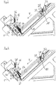
- Fig. 1 shows a device for slicing food products in the form of a multi-lane high-performance slicer with an inclined during cutting continuous belt conveyor 10, which serves as a conveyor and with the same time several food products 12 along a conveying direction F of a cutting plane S supplied and cut.
- the side views in particular the Fig. 1 and 2 not shown multi track formation of Slicers is mainly in the perspective views of the 3 and 4 to recognize.
- the food products 12 may in particular be sausage, ham, cheese or similar products. These may be rod-shaped or bar-shaped and differ in terms of production in length.
- a downwardly angled front part 10 ' is provided, which can be arranged relative to the conveyor 10 pivotable or at a fixed angle to the conveyor 10.
- the Front part 10 ' may also be designed as an active conveyor, but this is not mandatory.
- the conveyor 10 In the conveying direction F, the conveyor 10 is followed by a stationary front conveyor 11 in the form of an endless conveyor belt, which extends to just before the cutting plane S.
- the slicer comprises a working unit 16 with a base 18 and a plurality of holding elements 20 which form holding sections of the working unit 16, wherein a holding element 20 is provided for each track of the slicer.
- the holding elements 20 are in the functional position of Fig. 1 oriented parallel to the conveying direction F and press the products 12 on the product support formed by the stationary front conveyor 11. The holding elements 20 thus form hold-downs for the products 12.
- the holding elements 20 also each comprise a band belt 22, with which the products 12 can be actively moved in the conveying direction F.
- the promotion of the products 12 in the direction of the cutting plane S thus takes place with the aid of the endless conveyor belt 10 and the front conveyor 11, the belt straps 22 and a plurality of product holders designed as grippers 28, which respectively engage in a rear product end 30 of the food products 12.
- the product holders 28 may be passive insofar as they themselves do not serve as a drive for conveying the products 12 in the conveying direction F, but only for stabilizing the products 12 and later (cf. Fig. 2 ) are effective for retracting the product end pieces 30 and are pulled along by the products 12 during the movement in the conveying direction F, for example.
- the products 12 are thus transported by the active holding elements 20 and the stationary front conveyor 11 to the cutting plane.
- the working unit 16 comprises a pneumatic height adjustment drive 24 with which the distance of the base 18 from the front conveyor 11 along a height adjustment direction H can be adjusted.
- the working unit 16 includes pneumatic pivoting drives 26 with which the holding elements 20 relative to the base 18 of the in Fig. 1 shown Andschreibwolf can be pivoted into a locked position.
- Each holding element 20 is associated with its own pivoting drive 26, which comprises a piston / cylinder arrangement which is articulated at one end to the base 18 and at the other end to the respective holding element 20, wherein the holding elements 20 each hinged to the base 18th are connected, on a spaced from the axis of attack of the piston / cylinder arrangement pivot axis, so that a change in length of the piston / cylinder arrangement generates a pivoting movement of the respective holding element 20.
- pivoting drive 26 comprises a piston / cylinder arrangement which is articulated at one end to the base 18 and at the other end to the respective holding element 20, wherein the holding elements 20 each hinged to the base 18th are connected, on a spaced from the axis of attack of the piston / cylinder arrangement pivot axis, so that a change in length of the piston / cylinder arrangement generates a pivoting movement of the respective holding element 20.
- a blocking position of the holding elements 20 is in Fig. 2 shown.
- the holding elements 20 are in this case oriented perpendicular to the front conveyor 11 and form a barrier for the product end pieces 30th
- the holding elements 20 serve as hold-down for the products 12.
- the products 12 are held by the gripper 28 and conveyed to the sickle blade 14 by means of the endless conveyor belt 10, the front conveyor 11 and the belt straps 22 until the products 12 almost completely cut open.
- the gripper 28 against the Conveying direction F withdrawn.
- the height adjustment drive 24 moves the base 18 upwards along the height adjustment direction H, while the pivoting drive 26 pivots the holding elements 20 out of the pressing position into the blocking position.
- Fig. 2 shows remains in this slicer, the product feed is inclined, wherein for loading the product feeder a conveyor 10 comprehensive loading device from a substantially horizontal loading position according to Fig. 2 in which the products 12 to be sliced are brought into the inclined cutting position according to FIG Fig. 1 is pivoted.
- this embodiment is not mandatory and can be modified within the scope of the invention.
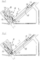
- Fig. 3 is a perspective view of the slicing according to Fig. 1 shown with four newly loaded products 12, which are supplied by the common endless conveyor belt 10 and the front conveyor 11 to the cutting blade 14. Also attached to a common carrier 32 gripper 28 can not track individual, but only together along or against the conveying direction F are moved by the driven carrier 32.
- Each track is assigned its own retaining element 20, which in each case comprises a separate pivoting drive 26.
- the common height adjustment drive 24 is provided which can move the base 18 together with the holding elements 20 along the height adjustment direction H.
- the holding elements 20 are designed to be yielding independently of each other, so that they can yield to the products 12 after a certain force, i. E. a pressed by means of the product holder 28 against its associated holding member 20 product 12, the way in the conveying direction F release a piece as soon as the force exceeds a predetermined amount.
- the products 12 can be individually relieved, if this is necessary due to a different length of the products 12, as will be explained in more detail below.
- FIG. 4 and 5 This situation is in Fig. 4 and 5 shown.
- the holding elements 20, which are associated with longer products 12, are deflected in the conveying direction F and thus already pivoted a little way from the original blocking position in the direction of the pressing position, but without completely clearing the way for the products 12, so that furthermore a holding force is effective with which the deflected holding elements 20 continue to oppose the respective products 12 in order to ensure that the product holders 28 engage as intended.
- the individual compliance of the holding elements 20 is realized by the effective manner of a spring, mutually independent pneumatic devices of the pivoting drives 26.
- the compliance behavior of the holding elements 20 can be adjusted on the pneumatic pivoting drives 26 or in another way.
- the setting is made in such a way that the products 12 on the one hand, a sufficiently large force is opposed, so that the gripper 28 can engage the rear product end 30, while on the other hand give the holding elements 20 before the products 12 are upset too much.
- the holding elements 20 can be further pivoted by means of the pivoting drives 26 from the locking position into the pressing position ( Fig. 6 ).
- the holding elements 20 are in constant contact with the products 12.
- the base 18 is moved by means of the height adjustment drive 24 down.
- the products 12 are conveyed by means of the endless conveyor belt 10, the front conveyor 11 and the gripper 28 in the conveying direction F to the cutting plane S.
- each pivoting drive 26 can be operated separately and independently of the respective other pivoting drives 26, so that the holding elements 20 not only give in individually, but can also be individually adjusted as desired.
- the holding elements 20 are in the pressing position, the products 12 are conveyed further along the conveying direction F until they reach the cutting plane and the slicing operation begins (cf. Fig. 1 ).
- the working unit 16 is thus multifunctional and serves as a product stop in the preparation of the slicing operation, as product hold-down during slicing and End Glaabweiser at the end of the slicing process, and also in the case of an active embodiment, the working unit 16 simultaneously with the hold function also fulfills a promotion function to the or to transport each product 12 to the cutting plane S, together with the active front conveyor 11, which may alternatively also be passive and serve only as a product support.
Claims (15)
- Dispositif de coupe de produits alimentaires (12), en particulier trancheuse à haute performance, comportant
une alimentation en produits qui comprend au moins un moyen de convoyage (10, 11) permettant d'amener au moins un produit (12) à un plan de coupe (S) dans lequel se déplace au moins un couteau de coupe (14) en particulier en rotation et/ou en révolution, et
au moins une unité de travail multifonctionnelle (16) pour manipuler au moins temporairement le produit (12), l'unité de travail (16) pouvant être déplacée jusque dans une position de pressage dans laquelle l'unité de travail (16) presse le produit (12) mobile en direction de convoyage (F) contre un support inférieur (11) du produit et/ou contre un appui latéral du produit, et une position de blocage dans laquelle l'unité de travail (16) vient contrecarrer un mouvement du produit (12) en direction de convoyage (F), dans lequel
l'unité de travail (16) est mobile en pivotement à partir de la position de blocage avec une composante en direction de convoyage (F) jusque dans une position libérant le chemin pour le produit (12). - Dispositif selon la revendication 1,
caractérisé en ce que
l'unité de travail (16) située dans la position de blocage fait office de butée pour l'extrémité avant du produit ou fait office de déflecteur pour un embout de produit (30) à enlever, en fonction de la situation de fonctionnement, et/ou
l'unité de travail (16) située dans la position de blocage est réalisée de manière souple vis-à-vis d'une force exercée en direction de convoyage (F), le comportement de souplesse étant en particulier réglable. - Dispositif selon la revendication 1 ou 2,
caractérisé en ce que
l'unité de travail (16) située dans la position de blocage est mobile par une force, dépassant une valeur seuil et exercée en direction de convoyage (F), avec une composante en direction de convoyage (F), en particulier à l'encontre de l'effet une force de retenue, la valeur seuil et/ou la force de retenue étant en particulier réglables et le mouvement de l'unité de travail (16) étant en particulier une partie d'un mouvement de déplacement de l'unité de travail (16) jusque dans la position de pressage. - Dispositif selon l'une des revendications précédentes,
caractérisé en ce que
l'unité de travail (16) est déplaçable depuis la position de blocage directement jusque dans la position de pressage ou inversement, et/ou en ce que l'unité de travail (16) est déplaçable depuis la position de blocage sans composante de mouvement dirigée en sens opposé à la direction de convoyage (F), et elle est en particulier mobile en pivotement avec une composante en direction de convoyage (F) jusque dans une position libérant le chemin pour le produit (12). - Dispositif selon l'une des revendications précédentes,
caractérisé en ce que
l'unité de travail (16) comprend au moins une portion de retenue déplaçable (20) qui exerce une fonction de pressage dans la position de pressage et une fonction de blocage du produit (12) dans la position de blocage, et la portion de retenue (20) présente une surface de retenue au moins sensiblement plane tournée vers le produit (12), qui s'étend de préférence dans la position de pressage au moins approximativement parallèlement à la direction de convoyage (F) et dans la position de blocage au moins approximativement perpendiculairement à la direction de convoyage (F) et/ou en ce que la position de l'unité de travail (16), en particulier la distance de l'unité de travail (16) vis-à-vis du support inférieur du produit et/ou de l'appui latéral du produit est variable. - Dispositif selon l'une des revendications précédentes,
caractérisé en ce que
un mouvement de déplacement de l'unité de travail (16) et un mouvement de modification de la position de l'unité de travail (16) sont indépendants l'un de l'autre, et pour chacun de ces deux mouvements il est prévu en particulier un entraînement distinct (24, 26), ou
en ce qu'un mouvement de déplacement de l'unité de travail (16) et un mouvement de modification de la position de l'unité de travail (16) sont couplés à force l'un avec l'autre. - Dispositif selon l'une des revendications précédentes,
caractérisé en ce que
l'unité de travail (16) comprend une embase (18) et une portion de retenue (20) pour le produit (12), sur l'embase (18), la position de l'embase (18) étant variable et la portion de retenue (20) étant réglable, en particulier la portion de retenue (20) étant mobile par rapport à l'embase (18). - Dispositif selon la revendication 7,
caractérisé en ce que
un mouvement de l'embase (18) pour modifier la position et un mouvement de déplacement de la portion de retenue (20) sont indépendants l'un de l'autre et peuvent être provoqués en particulier au moyen d'entraînements distincts (24, 26), et/ou
un mouvement de modification de la position de l'embase (18) et un mouvement de déplacement de la portion de retenue (20) peuvent être déviés d'un seul mouvement de l'unité de travail (16), et en particulier le mouvement de l'unité de travail (16) est provoqué au moyen d'un seul entraînement et/ou
en ce que l'unité de travail (16), en particulier une portion de retenue (20) de l'unité de travail (16), est réalisée sous forme d'entraînement au moins temporairement efficace pour le produit. - Dispositif selon l'une des revendications précédentes,
caractérisé en ce que
l'alimentation en produits est réalisée en plusieurs traces afin de couper plusieurs produits (12) simultanément, l'unité de travail (16) pouvant fonctionner individuellement pour chaque trace,
dans lequel en particulier l'unité de travail (16) comprend une portion de retenue (20) déplaçable pour chaque trace, qui exerce une fonction de pressage dans une position de pressage et une fonction de blocage du produit (12) dans une position de blocage, les portions de retenue (20) pouvant fonctionner indépendamment les unes des autres,
dans lequel
les portions de retenue (20) sont montées sur une embase commune (18) de l'unité de travail (16) et sont déplaçables par rapport à l'embase (18) indépendant les unes des autres,
et en particulier la position de l'embase (18), en particulier sa distance du support inférieur (11) du produit et/ou de l'appui latéral du produit, est variable. - Dispositif selon la revendication 9,
caractérisé en ce que
pour l'embase (18) et pour chacune des portions de retenue (20), il est prévu un entraînement respectif propre (24, 26). - Procédé de coupe de produits alimentaires au moyen d'un dispositif selon l'une des revendication précédentes, dans lequel
au moyen d'une alimentation en produits qui comprend au moins un moyen de convoyage (10, 11), au moins un produit est amené à un plan de coupe (S) dans lequel se déplace au moins un couteau de coupe (14) en particulier en rotation et/ou en révolution, et
au moins une unité de travail multifonctionnelle (16) est déplacée, en fonction de la situation de fonctionnement, jusque dans une position de pressage dans laquelle l'unité de travail (16) presse le produit (12), mouvant en direction de convoyage (F), contre un support inférieur (11) du produit et/ou contre un appui latéral du produit, ou jusque dans une position de blocage dans laquelle l'unité de travail (16) vient contrecarrer un mouvement du produit (12) en direction de convoyage (F),
dans lequel
l'unité de travail (16) est pivotée à partir de la position de blocage avec une composante en direction de convoyage (F) jusque dans une position de pressage libérant le chemin pour le produit (12). - Procédé selon la revendication 11,
caractérisé en ce que
avant de commencer à couper, l'unité de travail (16) est déplacée jusque dans la position de blocage afin de servir de butée pour l'extrémité avant du produit lorsque l'extrémité arrière (30) du produit est sollicitée à l'aide d'un porte-produit (28) du moyen de convoyage (10), ensuite elle est déplacée jusque dans la position de pressage pour presser le produit (12) contre le support de produit (11) et/ou contre l'appui de produit, pendant la coupe, et elle est déplacée en retour dans la position de blocage après la coupe pour au moins soutenir un enlèvement d'un embout de produit (30). - Procédé selon la revendication 11 ou 12,
caractérisé en ce que
l'unité de travail (16) est en contact avec le produit (12) au moins pendant un mouvement de déplacement depuis la position de blocage jusque dans la position de pressage. - Procédé selon l'une des revendication 11 à 13,
caractérisé en ce que
pendant un mouvement de déplacement de l'unité de travail (16) depuis la position de blocage jusque dans la position de pressage, le produit (12) est amené au plan de coupe (S). - Procédé selon l'une des revendication 11 à 14,
caractérisé en ce que
pendant un mouvement de déplacement de l'unité de travail (16) depuis la position de blocage jusque dans la position de pressage, le porte-produit (28) demeure dans sa position ou est déplacé en direction de convoyage (F),
et/ou
pendant le mouvement de déplacement de l'unité de travail (16) depuis la position de pressage jusque dans la position de blocage, le porte-produit (28) est déplacé en sens opposé à la direction de convoyage (F).
Priority Applications (2)
| Application Number | Priority Date | Filing Date | Title |
|---|---|---|---|
| EP17206542.7A EP3332928B1 (fr) | 2012-08-20 | 2013-07-30 | Dispositif de découpe de produits alimentaires |
| PL13745627T PL2885115T3 (pl) | 2012-08-20 | 2013-07-30 | Urządzenie i sposób krojenia produktów spożywczych |
Applications Claiming Priority (2)
| Application Number | Priority Date | Filing Date | Title |
|---|---|---|---|
| DE102012214741.1A DE102012214741A1 (de) | 2012-08-20 | 2012-08-20 | Vorrichtung und Verfahren zum Aufschneiden von Lebensmittelprodukten |
| PCT/EP2013/066030 WO2014029590A1 (fr) | 2012-08-20 | 2013-07-30 | Dispositif et procédé de découpe de produits alimentaires |
Related Child Applications (2)
| Application Number | Title | Priority Date | Filing Date |
|---|---|---|---|
| EP17206542.7A Division EP3332928B1 (fr) | 2012-08-20 | 2013-07-30 | Dispositif de découpe de produits alimentaires |
| EP17206542.7A Division-Into EP3332928B1 (fr) | 2012-08-20 | 2013-07-30 | Dispositif de découpe de produits alimentaires |
Publications (2)
| Publication Number | Publication Date |
|---|---|
| EP2885115A1 EP2885115A1 (fr) | 2015-06-24 |
| EP2885115B1 true EP2885115B1 (fr) | 2018-04-18 |
Family
ID=48918387
Family Applications (2)
| Application Number | Title | Priority Date | Filing Date |
|---|---|---|---|
| EP17206542.7A Active EP3332928B1 (fr) | 2012-08-20 | 2013-07-30 | Dispositif de découpe de produits alimentaires |
| EP13745627.3A Active EP2885115B1 (fr) | 2012-08-20 | 2013-07-30 | Dispositif et méthode pour la découpe de produits alimentaires |
Family Applications Before (1)
| Application Number | Title | Priority Date | Filing Date |
|---|---|---|---|
| EP17206542.7A Active EP3332928B1 (fr) | 2012-08-20 | 2013-07-30 | Dispositif de découpe de produits alimentaires |
Country Status (10)
| Country | Link |
|---|---|
| US (2) | US10307927B2 (fr) |
| EP (2) | EP3332928B1 (fr) |
| JP (1) | JP6200504B2 (fr) |
| CN (1) | CN104619470B (fr) |
| BR (1) | BR112015003573B1 (fr) |
| DE (1) | DE102012214741A1 (fr) |
| ES (2) | ES2773792T3 (fr) |
| NZ (1) | NZ705255A (fr) |
| PL (1) | PL2885115T3 (fr) |
| WO (1) | WO2014029590A1 (fr) |
Cited By (1)
| Publication number | Priority date | Publication date | Assignee | Title |
|---|---|---|---|---|
| DE102020122957B3 (de) | 2020-09-02 | 2022-01-13 | Bizerba SE & Co. KG | Scheibenschneidmaschine mit Produkterkennung |
Families Citing this family (24)
| Publication number | Priority date | Publication date | Assignee | Title |
|---|---|---|---|---|
| DE102012214741A1 (de) | 2012-08-20 | 2014-02-20 | Textor Maschinenbau GmbH | Vorrichtung und Verfahren zum Aufschneiden von Lebensmittelprodukten |
| DE102012109247A1 (de) | 2012-09-28 | 2014-04-03 | Gea Food Solutions Germany Gmbh | Vorrichtung und Verfahren zur kontinuierlichen Erzeugung von Portionen |
| DE102014112800A1 (de) * | 2014-09-05 | 2016-03-10 | Weber Maschinenbau Gmbh Breidenbach | Aufschneidevorrichtung |
| CH710403B1 (de) | 2014-11-24 | 2019-06-14 | Multivac Haggenmueller Kg | Aufschnittschneidmaschine. |
| DE102015107716A1 (de) * | 2015-05-18 | 2016-11-24 | Weber Maschinenbau Gmbh Breidenbach | Zuführvorrichtung |
| DE102015110533A1 (de) | 2015-06-30 | 2017-01-05 | Weber Maschinenbau Gmbh Breidenbach | Zuführvorrichtung |
| EP3341168B1 (fr) | 2015-08-27 | 2020-03-18 | GEA Food Solutions Germany GmbH | Dispositif de tranchage doté d'un moyen de butée |
| CN106493776A (zh) * | 2015-09-07 | 2017-03-15 | 申晓丽 | 半手动药材切片机 |
| DE102016101753A1 (de) | 2016-02-01 | 2017-08-03 | Textor Maschinenbau GmbH | Aufschneiden von lebensmittelprodukten |
| WO2017186498A1 (fr) * | 2016-04-29 | 2017-11-02 | Gea Food Solutions Germany Gmbh | Dispositif de tranchage à butée réglable |
| DE102016118707A1 (de) * | 2016-10-04 | 2018-04-05 | Weber Maschinenbau Gmbh Breidenbach | Vorrichtung und Verfahren zum Aufschneiden von Lebensmittelprodukten sowie Verfahren zum Erkennen des Anfangs eines Lebensmittelprodukts |
| US10639798B2 (en) | 2017-01-04 | 2020-05-05 | Provisur Technologies, Inc. | Gripper actuating system in a food processing machine |
| US10160602B2 (en) | 2017-01-04 | 2018-12-25 | Provisur Technologies, Inc. | Configurable in-feed for a food processing machine |
| US9950869B1 (en) | 2017-01-04 | 2018-04-24 | Provisur Technologies, Inc. | Belt tensioner in a food processing machine |
| US10836065B2 (en) | 2017-01-04 | 2020-11-17 | Provisur Technologies, Inc. | Exposed load cell in a food processing machine |
| DE102017123058A1 (de) * | 2017-10-05 | 2019-04-11 | Tpv Gmbh | Verfahren zum Aufschneiden eines Lebensmittelstrangs sowie Schneidvorrichtung |
| US11148313B2 (en) * | 2018-01-26 | 2021-10-19 | Provisur Technologies, Inc. | Food log slicing apparatus for slicing multiple layers of stacked food logs |
| US11198565B2 (en) | 2019-02-19 | 2021-12-14 | Provisur Technologies, Inc. | Multi-presentation slicing conveyor apparatus |
| DE102019109145A1 (de) | 2019-04-08 | 2020-10-08 | Weber Maschinenbau Gmbh Breidenbach | Aufschneiden von lebensmittelprodukten |
| DE102019110026A1 (de) * | 2019-04-16 | 2020-10-22 | Tvi Entwicklung Und Produktion Gmbh | Schneidemaschine sowie Verfahren zum Aufschneiden eines Laibes in Scheiben |
| CN110604329A (zh) * | 2019-09-19 | 2019-12-24 | 邳州中秋食品有限公司 | 一种食品加工设备及生产方法 |
| DE102020110424A1 (de) | 2020-04-16 | 2021-10-21 | Multivac Sepp Haggenmüller Se & Co. Kg | Aufschneide-Maschine |
| DE102020110425A1 (de) | 2020-04-16 | 2021-10-21 | Multivac Sepp Haggenmüller Se & Co. Kg | Aufschneide-Maschine |
| CN114274192B (zh) * | 2021-11-17 | 2024-03-08 | 盒马(中国)有限公司 | 一种切割装置及方法 |
Citations (1)
| Publication number | Priority date | Publication date | Assignee | Title |
|---|---|---|---|---|
| DE102007063112A1 (de) * | 2007-12-23 | 2009-07-23 | Dipl.-Ing. Schindler & Wagner Gmbh & Co. Kg | Schneidmaschine |
Family Cites Families (24)
| Publication number | Priority date | Publication date | Assignee | Title |
|---|---|---|---|---|
| US1976825A (en) * | 1930-01-06 | 1934-10-16 | Us Slicing Machine Co | Bacon slicing machine |
| US2038770A (en) * | 1932-09-29 | 1936-04-28 | Ind Patents Corp | Slicing machine |
| GB538919A (en) * | 1939-03-28 | 1941-08-21 | Berkel & Parnall Mach Mfg Co | Improvements relating to slicing machines |
| US2768666A (en) * | 1953-10-02 | 1956-10-30 | Wilson & Co Inc | Automatic slice thickness control for bacon slicing machine |
| US3354920A (en) * | 1965-08-02 | 1967-11-28 | Swift & Co | Bacon slicing apparatus |
| US4309927A (en) * | 1979-12-05 | 1982-01-12 | Cashin Systems Corporation | Continuous cold cut slicing machine |
| US4329900A (en) * | 1980-01-11 | 1982-05-18 | Cashin Systems Corporation | Bacon slicing machine |
| DE3018446A1 (de) * | 1980-05-14 | 1981-11-19 | Roland 8961 Wiggensbach Glaenzer | Verfahren und vorrichtung zum scheiben-schneiden von lebensmittelwaren |
| US4548108A (en) * | 1983-08-08 | 1985-10-22 | Cashin Systems Corporation | Slicing machine |
| GB8800920D0 (en) * | 1988-01-15 | 1988-02-17 | Thurne Eng Co Ltd | Feeding device for slicing machine |
| US5271304A (en) | 1990-07-03 | 1993-12-21 | Carruthers Equipment Co. | Automatic food slicing machine |
| BR9306279A (pt) * | 1992-04-23 | 1998-06-30 | Townsend Engineering Co | Máquina fatiadora de carne e processo para a sua utilização |
| JP4032146B2 (ja) | 1997-06-04 | 2008-01-16 | 株式会社日本キャリア工業 | ブロック肉スライサー |
| ES2244112T3 (es) * | 1998-01-24 | 2005-12-01 | Magurit Gefrierschneider Gmbh | Dispositivo para el desmenuzamiento de alimentos. |
| JP4145413B2 (ja) | 1999-03-31 | 2008-09-03 | プリマハム株式会社 | スライスハム製品の製造方法及びその装置 |
| CN2559459Y (zh) * | 2002-08-22 | 2003-07-09 | 河南环宇实业投资有限公司 | 自动切菜机 |
| US20050252354A1 (en) * | 2004-05-14 | 2005-11-17 | Tzu-Feng Tseng | Flat media cutting device |
| US7603936B2 (en) * | 2005-03-05 | 2009-10-20 | Formax, Inc. | Loaf seam synchronization device for continuous loaf feed slicing machine |
| JP4190016B2 (ja) * | 2005-11-08 | 2008-12-03 | 株式会社日本キャリア工業 | 丸刃を使用する食肉スライサー |
| GB2436785A (en) * | 2007-02-15 | 2007-10-10 | Aew Delford Systems Ltd | Food slicing machines having moveable gates |
| US20090188355A1 (en) * | 2007-10-22 | 2009-07-30 | Lindee Scott A | Stack Completion and Scrap Discharge System for a Food Article Slicing Machine |
| DE102008019776A1 (de) | 2008-04-18 | 2009-10-22 | CFS Bühl GmbH | Verfahren, Vorrichtung sowie Messer zum Aufschneiden von Lebensmitteln |
| EP2844440B2 (fr) * | 2012-04-30 | 2021-11-03 | GEA Food Solutions Germany GmbH | Dispositif de tranchage doté d'un élément de préhension de produit |
| DE102012214741A1 (de) | 2012-08-20 | 2014-02-20 | Textor Maschinenbau GmbH | Vorrichtung und Verfahren zum Aufschneiden von Lebensmittelprodukten |
-
2012
- 2012-08-20 DE DE102012214741.1A patent/DE102012214741A1/de not_active Withdrawn
-
2013
- 2013-07-30 EP EP17206542.7A patent/EP3332928B1/fr active Active
- 2013-07-30 ES ES17206542T patent/ES2773792T3/es active Active
- 2013-07-30 EP EP13745627.3A patent/EP2885115B1/fr active Active
- 2013-07-30 ES ES13745627.3T patent/ES2673326T3/es active Active
- 2013-07-30 US US14/421,347 patent/US10307927B2/en active Active
- 2013-07-30 NZ NZ705255A patent/NZ705255A/en unknown
- 2013-07-30 WO PCT/EP2013/066030 patent/WO2014029590A1/fr active Application Filing
- 2013-07-30 CN CN201380044347.XA patent/CN104619470B/zh active Active
- 2013-07-30 PL PL13745627T patent/PL2885115T3/pl unknown
- 2013-07-30 JP JP2015527829A patent/JP6200504B2/ja active Active
- 2013-07-30 BR BR112015003573-6A patent/BR112015003573B1/pt active IP Right Grant
-
2019
- 2019-04-16 US US16/385,794 patent/US10836063B2/en active Active
Patent Citations (1)
| Publication number | Priority date | Publication date | Assignee | Title |
|---|---|---|---|---|
| DE102007063112A1 (de) * | 2007-12-23 | 2009-07-23 | Dipl.-Ing. Schindler & Wagner Gmbh & Co. Kg | Schneidmaschine |
Cited By (1)
| Publication number | Priority date | Publication date | Assignee | Title |
|---|---|---|---|---|
| DE102020122957B3 (de) | 2020-09-02 | 2022-01-13 | Bizerba SE & Co. KG | Scheibenschneidmaschine mit Produkterkennung |
Also Published As
| Publication number | Publication date |
|---|---|
| JP2015530932A (ja) | 2015-10-29 |
| EP3332928B1 (fr) | 2020-01-08 |
| US10307927B2 (en) | 2019-06-04 |
| EP3332928A1 (fr) | 2018-06-13 |
| ES2773792T3 (es) | 2020-07-14 |
| CN104619470B (zh) | 2017-07-25 |
| PL2885115T3 (pl) | 2018-09-28 |
| BR112015003573A2 (pt) | 2017-07-04 |
| US10836063B2 (en) | 2020-11-17 |
| DE102012214741A1 (de) | 2014-02-20 |
| CN104619470A (zh) | 2015-05-13 |
| JP6200504B2 (ja) | 2017-09-20 |
| US20190240857A1 (en) | 2019-08-08 |
| WO2014029590A1 (fr) | 2014-02-27 |
| NZ705255A (en) | 2017-07-28 |
| US20150202786A1 (en) | 2015-07-23 |
| ES2673326T3 (es) | 2018-06-21 |
| BR112015003573B1 (pt) | 2022-02-15 |
| EP2885115A1 (fr) | 2015-06-24 |
Similar Documents
| Publication | Publication Date | Title |
|---|---|---|
| EP2885115B1 (fr) | Dispositif et méthode pour la découpe de produits alimentaires | |
| EP3448641B1 (fr) | Trancheuse et procédé pour trancher des boudins élastiques, en particulier des boudins de viande | |
| EP3172020B1 (fr) | Dispositif de coupe | |
| EP2407285B1 (fr) | Dispositif et procédé destinés à la coupe de produits alimentaires | |
| EP2900440B2 (fr) | Dispositif et procédé de production continue de portions | |
| EP2537651A1 (fr) | Procédé et dispositif de coupe d'un tronçon d'aliments en tranches | |
| EP2384867B1 (fr) | Machine de découpage pour blocs de viande congelée | |
| EP3125696B1 (fr) | Dispositif et procédé pour séparer une couche superficielle de filets de poisson incluant la peau | |
| EP1995026B1 (fr) | Procédé pour découper des barres de produits alimentaires | |
| EP2127828B1 (fr) | Dispositif de séparation d'une pile utile d'une pile de sortie par coupe | |
| WO2017186498A1 (fr) | Dispositif de tranchage à butée réglable | |
| EP3341168B1 (fr) | Dispositif de tranchage doté d'un moyen de butée | |
| EP1704973B2 (fr) | Méthode et appareil pour couper des produits alimentaires allongés | |
| EP2543484B1 (fr) | Dispositif de coupe de produit alimentaire | |
| EP3380419B1 (fr) | Procédé et dispositif de mise en portions de tranches d'un produit alimentaire avec modification de forme, notamment pliage, de la portion | |
| EP2417860A1 (fr) | Dispositif et procédé de séparation de parties de balles d'un produit comprimé | |
| DE112015000508T5 (de) | Seitenladependelschneider | |
| DE102013218263A1 (de) | Schneidleiste mit einem integrierten Verschleißteil | |
| EP3645226B1 (fr) | Dispositif de coupe transversale et procédé permettant de stabiliser un bord de coupe lors d'une coupe par écrasement | |
| DE102016108318A1 (de) | Vorrichtung zum Raspeln, Reiben oder Würfeln von Nahrungsmitteln aus einem Produktstrang | |
| EP2436623B1 (fr) | Procédé et dispositif pour enlever une rangée de piles | |
| WO1984000715A1 (fr) | Dispositif de coupe pour couper des planches ou objets similaires | |
| EP3722057A1 (fr) | Découpage de produits alimentaires | |
| DE102020110424A1 (de) | Aufschneide-Maschine | |
| DE102007027531A1 (de) | Materialstrang-Behandlungsvorrichtung und Verfahren zur Behandlung eines Materialstrangs |
Legal Events
| Date | Code | Title | Description |
|---|---|---|---|
| PUAI | Public reference made under article 153(3) epc to a published international application that has entered the european phase |
Free format text: ORIGINAL CODE: 0009012 |
|
| 17P | Request for examination filed |
Effective date: 20150303 |
|
| AK | Designated contracting states |
Kind code of ref document: A1 Designated state(s): AL AT BE BG CH CY CZ DE DK EE ES FI FR GB GR HR HU IE IS IT LI LT LU LV MC MK MT NL NO PL PT RO RS SE SI SK SM TR |
|
| AX | Request for extension of the european patent |
Extension state: BA ME |
|
| DAX | Request for extension of the european patent (deleted) | ||
| 17Q | First examination report despatched |
Effective date: 20160425 |
|
| GRAP | Despatch of communication of intention to grant a patent |
Free format text: ORIGINAL CODE: EPIDOSNIGR1 |
|
| INTG | Intention to grant announced |
Effective date: 20171110 |
|
| GRAS | Grant fee paid |
Free format text: ORIGINAL CODE: EPIDOSNIGR3 |
|
| GRAA | (expected) grant |
Free format text: ORIGINAL CODE: 0009210 |
|
| AK | Designated contracting states |
Kind code of ref document: B1 Designated state(s): AL AT BE BG CH CY CZ DE DK EE ES FI FR GB GR HR HU IE IS IT LI LT LU LV MC MK MT NL NO PL PT RO RS SE SI SK SM TR |
|
| REG | Reference to a national code |
Ref country code: GB Ref legal event code: FG4D Free format text: NOT ENGLISH |
|
| REG | Reference to a national code |
Ref country code: CH Ref legal event code: EP |
|
| REG | Reference to a national code |
Ref country code: AT Ref legal event code: REF Ref document number: 989934 Country of ref document: AT Kind code of ref document: T Effective date: 20180515 |
|
| REG | Reference to a national code |
Ref country code: IE Ref legal event code: FG4D Free format text: LANGUAGE OF EP DOCUMENT: GERMAN |
|
| REG | Reference to a national code |
Ref country code: DE Ref legal event code: R096 Ref document number: 502013009959 Country of ref document: DE |
|
| REG | Reference to a national code |
Ref country code: ES Ref legal event code: FG2A Ref document number: 2673326 Country of ref document: ES Kind code of ref document: T3 Effective date: 20180621 |
|
| REG | Reference to a national code |
Ref country code: NL Ref legal event code: FP |
|
| REG | Reference to a national code |
Ref country code: LT Ref legal event code: MG4D |
|
| PG25 | Lapsed in a contracting state [announced via postgrant information from national office to epo] |
Ref country code: NO Free format text: LAPSE BECAUSE OF FAILURE TO SUBMIT A TRANSLATION OF THE DESCRIPTION OR TO PAY THE FEE WITHIN THE PRESCRIBED TIME-LIMIT Effective date: 20180718 Ref country code: SE Free format text: LAPSE BECAUSE OF FAILURE TO SUBMIT A TRANSLATION OF THE DESCRIPTION OR TO PAY THE FEE WITHIN THE PRESCRIBED TIME-LIMIT Effective date: 20180418 Ref country code: AL Free format text: LAPSE BECAUSE OF FAILURE TO SUBMIT A TRANSLATION OF THE DESCRIPTION OR TO PAY THE FEE WITHIN THE PRESCRIBED TIME-LIMIT Effective date: 20180418 Ref country code: BG Free format text: LAPSE BECAUSE OF FAILURE TO SUBMIT A TRANSLATION OF THE DESCRIPTION OR TO PAY THE FEE WITHIN THE PRESCRIBED TIME-LIMIT Effective date: 20180718 Ref country code: FI Free format text: LAPSE BECAUSE OF FAILURE TO SUBMIT A TRANSLATION OF THE DESCRIPTION OR TO PAY THE FEE WITHIN THE PRESCRIBED TIME-LIMIT Effective date: 20180418 Ref country code: LT Free format text: LAPSE BECAUSE OF FAILURE TO SUBMIT A TRANSLATION OF THE DESCRIPTION OR TO PAY THE FEE WITHIN THE PRESCRIBED TIME-LIMIT Effective date: 20180418 |
|
| PG25 | Lapsed in a contracting state [announced via postgrant information from national office to epo] |
Ref country code: RS Free format text: LAPSE BECAUSE OF FAILURE TO SUBMIT A TRANSLATION OF THE DESCRIPTION OR TO PAY THE FEE WITHIN THE PRESCRIBED TIME-LIMIT Effective date: 20180418 Ref country code: GR Free format text: LAPSE BECAUSE OF FAILURE TO SUBMIT A TRANSLATION OF THE DESCRIPTION OR TO PAY THE FEE WITHIN THE PRESCRIBED TIME-LIMIT Effective date: 20180719 Ref country code: LV Free format text: LAPSE BECAUSE OF FAILURE TO SUBMIT A TRANSLATION OF THE DESCRIPTION OR TO PAY THE FEE WITHIN THE PRESCRIBED TIME-LIMIT Effective date: 20180418 Ref country code: HR Free format text: LAPSE BECAUSE OF FAILURE TO SUBMIT A TRANSLATION OF THE DESCRIPTION OR TO PAY THE FEE WITHIN THE PRESCRIBED TIME-LIMIT Effective date: 20180418 |
|
| PG25 | Lapsed in a contracting state [announced via postgrant information from national office to epo] |
Ref country code: PT Free format text: LAPSE BECAUSE OF FAILURE TO SUBMIT A TRANSLATION OF THE DESCRIPTION OR TO PAY THE FEE WITHIN THE PRESCRIBED TIME-LIMIT Effective date: 20180820 |
|
| REG | Reference to a national code |
Ref country code: DE Ref legal event code: R097 Ref document number: 502013009959 Country of ref document: DE |
|
| PG25 | Lapsed in a contracting state [announced via postgrant information from national office to epo] |
Ref country code: DK Free format text: LAPSE BECAUSE OF FAILURE TO SUBMIT A TRANSLATION OF THE DESCRIPTION OR TO PAY THE FEE WITHIN THE PRESCRIBED TIME-LIMIT Effective date: 20180418 Ref country code: EE Free format text: LAPSE BECAUSE OF FAILURE TO SUBMIT A TRANSLATION OF THE DESCRIPTION OR TO PAY THE FEE WITHIN THE PRESCRIBED TIME-LIMIT Effective date: 20180418 Ref country code: SK Free format text: LAPSE BECAUSE OF FAILURE TO SUBMIT A TRANSLATION OF THE DESCRIPTION OR TO PAY THE FEE WITHIN THE PRESCRIBED TIME-LIMIT Effective date: 20180418 Ref country code: CZ Free format text: LAPSE BECAUSE OF FAILURE TO SUBMIT A TRANSLATION OF THE DESCRIPTION OR TO PAY THE FEE WITHIN THE PRESCRIBED TIME-LIMIT Effective date: 20180418 Ref country code: RO Free format text: LAPSE BECAUSE OF FAILURE TO SUBMIT A TRANSLATION OF THE DESCRIPTION OR TO PAY THE FEE WITHIN THE PRESCRIBED TIME-LIMIT Effective date: 20180418 |
|
| PLBE | No opposition filed within time limit |
Free format text: ORIGINAL CODE: 0009261 |
|
| STAA | Information on the status of an ep patent application or granted ep patent |
Free format text: STATUS: NO OPPOSITION FILED WITHIN TIME LIMIT |
|
| PG25 | Lapsed in a contracting state [announced via postgrant information from national office to epo] |
Ref country code: SM Free format text: LAPSE BECAUSE OF FAILURE TO SUBMIT A TRANSLATION OF THE DESCRIPTION OR TO PAY THE FEE WITHIN THE PRESCRIBED TIME-LIMIT Effective date: 20180418 |
|
| REG | Reference to a national code |
Ref country code: CH Ref legal event code: PL |
|
| 26N | No opposition filed |
Effective date: 20190121 |
|
| PG25 | Lapsed in a contracting state [announced via postgrant information from national office to epo] |
Ref country code: LU Free format text: LAPSE BECAUSE OF NON-PAYMENT OF DUE FEES Effective date: 20180730 Ref country code: MC Free format text: LAPSE BECAUSE OF FAILURE TO SUBMIT A TRANSLATION OF THE DESCRIPTION OR TO PAY THE FEE WITHIN THE PRESCRIBED TIME-LIMIT Effective date: 20180418 |
|
| REG | Reference to a national code |
Ref country code: BE Ref legal event code: MM Effective date: 20180731 |
|
| PG25 | Lapsed in a contracting state [announced via postgrant information from national office to epo] |
Ref country code: CH Free format text: LAPSE BECAUSE OF NON-PAYMENT OF DUE FEES Effective date: 20180731 Ref country code: LI Free format text: LAPSE BECAUSE OF NON-PAYMENT OF DUE FEES Effective date: 20180731 Ref country code: FR Free format text: LAPSE BECAUSE OF NON-PAYMENT OF DUE FEES Effective date: 20180731 |
|
| REG | Reference to a national code |
Ref country code: IE Ref legal event code: MM4A |
|
| PG25 | Lapsed in a contracting state [announced via postgrant information from national office to epo] |
Ref country code: BE Free format text: LAPSE BECAUSE OF NON-PAYMENT OF DUE FEES Effective date: 20180731 Ref country code: SI Free format text: LAPSE BECAUSE OF FAILURE TO SUBMIT A TRANSLATION OF THE DESCRIPTION OR TO PAY THE FEE WITHIN THE PRESCRIBED TIME-LIMIT Effective date: 20180418 |
|
| PG25 | Lapsed in a contracting state [announced via postgrant information from national office to epo] |
Ref country code: IE Free format text: LAPSE BECAUSE OF NON-PAYMENT OF DUE FEES Effective date: 20180730 |
|
| REG | Reference to a national code |
Ref country code: AT Ref legal event code: MM01 Ref document number: 989934 Country of ref document: AT Kind code of ref document: T Effective date: 20180730 |
|
| PG25 | Lapsed in a contracting state [announced via postgrant information from national office to epo] |
Ref country code: AT Free format text: LAPSE BECAUSE OF NON-PAYMENT OF DUE FEES Effective date: 20180730 |
|
| PG25 | Lapsed in a contracting state [announced via postgrant information from national office to epo] |
Ref country code: MT Free format text: LAPSE BECAUSE OF FAILURE TO SUBMIT A TRANSLATION OF THE DESCRIPTION OR TO PAY THE FEE WITHIN THE PRESCRIBED TIME-LIMIT Effective date: 20180418 |
|
| PG25 | Lapsed in a contracting state [announced via postgrant information from national office to epo] |
Ref country code: TR Free format text: LAPSE BECAUSE OF FAILURE TO SUBMIT A TRANSLATION OF THE DESCRIPTION OR TO PAY THE FEE WITHIN THE PRESCRIBED TIME-LIMIT Effective date: 20180418 |
|
| PG25 | Lapsed in a contracting state [announced via postgrant information from national office to epo] |
Ref country code: HU Free format text: LAPSE BECAUSE OF FAILURE TO SUBMIT A TRANSLATION OF THE DESCRIPTION OR TO PAY THE FEE WITHIN THE PRESCRIBED TIME-LIMIT; INVALID AB INITIO Effective date: 20130730 |
|
| PG25 | Lapsed in a contracting state [announced via postgrant information from national office to epo] |
Ref country code: MK Free format text: LAPSE BECAUSE OF NON-PAYMENT OF DUE FEES Effective date: 20180418 Ref country code: CY Free format text: LAPSE BECAUSE OF FAILURE TO SUBMIT A TRANSLATION OF THE DESCRIPTION OR TO PAY THE FEE WITHIN THE PRESCRIBED TIME-LIMIT Effective date: 20180418 |
|
| PG25 | Lapsed in a contracting state [announced via postgrant information from national office to epo] |
Ref country code: IS Free format text: LAPSE BECAUSE OF FAILURE TO SUBMIT A TRANSLATION OF THE DESCRIPTION OR TO PAY THE FEE WITHIN THE PRESCRIBED TIME-LIMIT Effective date: 20180818 |
|
| P01 | Opt-out of the competence of the unified patent court (upc) registered |
Effective date: 20230522 |
|
| PGFP | Annual fee paid to national office [announced via postgrant information from national office to epo] |
Ref country code: NL Payment date: 20230720 Year of fee payment: 11 |
|
| PGFP | Annual fee paid to national office [announced via postgrant information from national office to epo] |
Ref country code: IT Payment date: 20230731 Year of fee payment: 11 Ref country code: GB Payment date: 20230724 Year of fee payment: 11 Ref country code: ES Payment date: 20230821 Year of fee payment: 11 |
|
| PGFP | Annual fee paid to national office [announced via postgrant information from national office to epo] |
Ref country code: PL Payment date: 20230718 Year of fee payment: 11 Ref country code: DE Payment date: 20230720 Year of fee payment: 11 |