EP2877242B1 - Dispositif de transmission auto-résonnant - Google Patents
Dispositif de transmission auto-résonnant Download PDFInfo
- Publication number
- EP2877242B1 EP2877242B1 EP13822480.3A EP13822480A EP2877242B1 EP 2877242 B1 EP2877242 B1 EP 2877242B1 EP 13822480 A EP13822480 A EP 13822480A EP 2877242 B1 EP2877242 B1 EP 2877242B1
- Authority
- EP
- European Patent Office
- Prior art keywords
- antenna
- power
- unit
- implant
- nerve
- Prior art date
- Legal status (The legal status is an assumption and is not a legal conclusion. Google has not performed a legal analysis and makes no representation as to the accuracy of the status listed.)
- Active
Links
- 239000007943 implant Substances 0.000 claims description 187
- 210000005036 nerve Anatomy 0.000 claims description 90
- 238000003860 storage Methods 0.000 claims description 41
- 210000003205 muscle Anatomy 0.000 claims description 19
- 230000010355 oscillation Effects 0.000 claims description 19
- 238000012546 transfer Methods 0.000 claims description 15
- 230000036772 blood pressure Effects 0.000 claims description 14
- 201000002859 sleep apnea Diseases 0.000 claims description 13
- 206010020772 Hypertension Diseases 0.000 claims description 11
- 210000001932 glossopharyngeal nerve Anatomy 0.000 claims description 9
- 108091008698 baroreceptors Proteins 0.000 claims description 8
- 210000001774 pressoreceptor Anatomy 0.000 claims description 8
- 210000001169 hypoglossal nerve Anatomy 0.000 claims description 6
- 238000002560 therapeutic procedure Methods 0.000 claims description 6
- 230000008602 contraction Effects 0.000 claims description 5
- 239000000758 substrate Substances 0.000 claims description 5
- 210000004204 blood vessel Anatomy 0.000 claims 2
- 230000008878 coupling Effects 0.000 description 74
- 238000010168 coupling process Methods 0.000 description 74
- 238000005859 coupling reaction Methods 0.000 description 74
- 239000003990 capacitor Substances 0.000 description 43
- 230000000638 stimulation Effects 0.000 description 29
- 102000004310 Ion Channels Human genes 0.000 description 28
- 230000008859 change Effects 0.000 description 24
- 230000004044 response Effects 0.000 description 23
- 230000005540 biological transmission Effects 0.000 description 19
- 230000001939 inductive effect Effects 0.000 description 19
- 239000010410 layer Substances 0.000 description 17
- 238000002513 implantation Methods 0.000 description 16
- 230000033001 locomotion Effects 0.000 description 16
- 239000000463 material Substances 0.000 description 16
- 208000001797 obstructive sleep apnea Diseases 0.000 description 16
- 238000004891 communication Methods 0.000 description 14
- 230000005684 electric field Effects 0.000 description 13
- 230000001965 increasing effect Effects 0.000 description 13
- 230000001537 neural effect Effects 0.000 description 13
- 210000001519 tissue Anatomy 0.000 description 11
- 230000004913 activation Effects 0.000 description 10
- 230000007423 decrease Effects 0.000 description 10
- 230000000694 effects Effects 0.000 description 10
- 210000002569 neuron Anatomy 0.000 description 10
- 230000003071 parasitic effect Effects 0.000 description 10
- 230000005764 inhibitory process Effects 0.000 description 9
- 239000012528 membrane Substances 0.000 description 9
- 238000000034 method Methods 0.000 description 9
- 208000019695 Migraine disease Diseases 0.000 description 8
- 230000000875 corresponding effect Effects 0.000 description 8
- 230000036982 action potential Effects 0.000 description 7
- 238000006073 displacement reaction Methods 0.000 description 7
- 230000006870 function Effects 0.000 description 7
- 230000004007 neuromodulation Effects 0.000 description 7
- 230000000903 blocking effect Effects 0.000 description 6
- 210000004556 brain Anatomy 0.000 description 6
- 210000000170 cell membrane Anatomy 0.000 description 6
- 239000002243 precursor Substances 0.000 description 6
- 230000029058 respiratory gaseous exchange Effects 0.000 description 6
- 239000000853 adhesive Substances 0.000 description 5
- 230000001070 adhesive effect Effects 0.000 description 5
- 230000004075 alteration Effects 0.000 description 5
- 230000037007 arousal Effects 0.000 description 5
- 239000004020 conductor Substances 0.000 description 5
- 239000000835 fiber Substances 0.000 description 5
- 230000003993 interaction Effects 0.000 description 5
- 238000012544 monitoring process Methods 0.000 description 5
- 230000008058 pain sensation Effects 0.000 description 5
- 210000002254 renal artery Anatomy 0.000 description 5
- 206010021143 Hypoxia Diseases 0.000 description 4
- DGAQECJNVWCQMB-PUAWFVPOSA-M Ilexoside XXIX Chemical compound C[C@@H]1CC[C@@]2(CC[C@@]3(C(=CC[C@H]4[C@]3(CC[C@@H]5[C@@]4(CC[C@@H](C5(C)C)OS(=O)(=O)[O-])C)C)[C@@H]2[C@]1(C)O)C)C(=O)O[C@H]6[C@@H]([C@H]([C@@H]([C@H](O6)CO)O)O)O.[Na+] DGAQECJNVWCQMB-PUAWFVPOSA-M 0.000 description 4
- 239000004642 Polyimide Substances 0.000 description 4
- 206010041235 Snoring Diseases 0.000 description 4
- 238000009825 accumulation Methods 0.000 description 4
- 210000001715 carotid artery Anatomy 0.000 description 4
- 230000007613 environmental effect Effects 0.000 description 4
- 208000018875 hypoxemia Diseases 0.000 description 4
- BASFCYQUMIYNBI-UHFFFAOYSA-N platinum Chemical compound [Pt] BASFCYQUMIYNBI-UHFFFAOYSA-N 0.000 description 4
- 229920001721 polyimide Polymers 0.000 description 4
- 239000011253 protective coating Substances 0.000 description 4
- 239000011734 sodium Substances 0.000 description 4
- 230000002889 sympathetic effect Effects 0.000 description 4
- 210000003901 trigeminal nerve Anatomy 0.000 description 4
- 208000000884 Airway Obstruction Diseases 0.000 description 3
- 206010019233 Headaches Diseases 0.000 description 3
- 206010027603 Migraine headaches Diseases 0.000 description 3
- 208000002193 Pain Diseases 0.000 description 3
- ZLMJMSJWJFRBEC-UHFFFAOYSA-N Potassium Chemical compound [K] ZLMJMSJWJFRBEC-UHFFFAOYSA-N 0.000 description 3
- 230000003321 amplification Effects 0.000 description 3
- 210000003403 autonomic nervous system Anatomy 0.000 description 3
- 238000005452 bending Methods 0.000 description 3
- 239000000560 biocompatible material Substances 0.000 description 3
- 230000033228 biological regulation Effects 0.000 description 3
- 239000008280 blood Substances 0.000 description 3
- 210000004369 blood Anatomy 0.000 description 3
- 230000003247 decreasing effect Effects 0.000 description 3
- 208000037265 diseases, disorders, signs and symptoms Diseases 0.000 description 3
- 238000004519 manufacturing process Methods 0.000 description 3
- 206010027599 migraine Diseases 0.000 description 3
- 210000002161 motor neuron Anatomy 0.000 description 3
- 230000004118 muscle contraction Effects 0.000 description 3
- 230000007383 nerve stimulation Effects 0.000 description 3
- 239000002858 neurotransmitter agent Substances 0.000 description 3
- 238000003199 nucleic acid amplification method Methods 0.000 description 3
- 210000001428 peripheral nervous system Anatomy 0.000 description 3
- 210000001184 pharyngeal muscle Anatomy 0.000 description 3
- 229910052700 potassium Inorganic materials 0.000 description 3
- 239000011591 potassium Substances 0.000 description 3
- 230000035945 sensitivity Effects 0.000 description 3
- 210000001044 sensory neuron Anatomy 0.000 description 3
- 238000000926 separation method Methods 0.000 description 3
- 239000002356 single layer Substances 0.000 description 3
- 229910052708 sodium Inorganic materials 0.000 description 3
- 230000002123 temporal effect Effects 0.000 description 3
- 241001669679 Eleotris Species 0.000 description 2
- 229920000106 Liquid crystal polymer Polymers 0.000 description 2
- 239000004977 Liquid-crystal polymers (LCPs) Substances 0.000 description 2
- 239000004696 Poly ether ether ketone Substances 0.000 description 2
- 230000009471 action Effects 0.000 description 2
- 238000013459 approach Methods 0.000 description 2
- 230000008901 benefit Effects 0.000 description 2
- 210000003169 central nervous system Anatomy 0.000 description 2
- 239000007933 dermal patch Substances 0.000 description 2
- 238000011161 development Methods 0.000 description 2
- 230000003292 diminished effect Effects 0.000 description 2
- 201000010099 disease Diseases 0.000 description 2
- 238000005538 encapsulation Methods 0.000 description 2
- 230000007717 exclusion Effects 0.000 description 2
- PCHJSUWPFVWCPO-UHFFFAOYSA-N gold Chemical compound [Au] PCHJSUWPFVWCPO-UHFFFAOYSA-N 0.000 description 2
- 229910052737 gold Inorganic materials 0.000 description 2
- 239000010931 gold Substances 0.000 description 2
- 230000002401 inhibitory effect Effects 0.000 description 2
- 238000003780 insertion Methods 0.000 description 2
- 230000037431 insertion Effects 0.000 description 2
- 210000003734 kidney Anatomy 0.000 description 2
- 230000004048 modification Effects 0.000 description 2
- 238000012986 modification Methods 0.000 description 2
- 210000005037 parasympathetic nerve Anatomy 0.000 description 2
- 230000036961 partial effect Effects 0.000 description 2
- 230000000737 periodic effect Effects 0.000 description 2
- 230000002093 peripheral effect Effects 0.000 description 2
- 230000004962 physiological condition Effects 0.000 description 2
- 229910052697 platinum Inorganic materials 0.000 description 2
- 229920003229 poly(methyl methacrylate) Polymers 0.000 description 2
- 229920002530 polyetherether ketone Polymers 0.000 description 2
- 239000004926 polymethyl methacrylate Substances 0.000 description 2
- 229920001296 polysiloxane Polymers 0.000 description 2
- 229910001414 potassium ion Inorganic materials 0.000 description 2
- 230000008569 process Effects 0.000 description 2
- 230000001902 propagating effect Effects 0.000 description 2
- 230000001105 regulatory effect Effects 0.000 description 2
- 229910001415 sodium ion Inorganic materials 0.000 description 2
- 210000002784 stomach Anatomy 0.000 description 2
- 238000007920 subcutaneous administration Methods 0.000 description 2
- 239000000126 substance Substances 0.000 description 2
- 230000001225 therapeutic effect Effects 0.000 description 2
- ZNOCGWVLWPVKAO-UHFFFAOYSA-N trimethoxy(phenyl)silane Chemical compound CO[Si](OC)(OC)C1=CC=CC=C1 ZNOCGWVLWPVKAO-UHFFFAOYSA-N 0.000 description 2
- 238000009966 trimming Methods 0.000 description 2
- 238000004804 winding Methods 0.000 description 2
- SFLSHLFXELFNJZ-QMMMGPOBSA-N (-)-norepinephrine Chemical compound NC[C@H](O)C1=CC=C(O)C(O)=C1 SFLSHLFXELFNJZ-QMMMGPOBSA-N 0.000 description 1
- UCTWMZQNUQWSLP-VIFPVBQESA-N (R)-adrenaline Chemical compound CNC[C@H](O)C1=CC=C(O)C(O)=C1 UCTWMZQNUQWSLP-VIFPVBQESA-N 0.000 description 1
- 229930182837 (R)-adrenaline Natural products 0.000 description 1
- VRBFTYUMFJWSJY-UHFFFAOYSA-N 28804-46-8 Chemical compound ClC1CC(C=C2)=CC=C2C(Cl)CC2=CC=C1C=C2 VRBFTYUMFJWSJY-UHFFFAOYSA-N 0.000 description 1
- 102000015427 Angiotensins Human genes 0.000 description 1
- 108010064733 Angiotensins Proteins 0.000 description 1
- 208000008035 Back Pain Diseases 0.000 description 1
- RYGMFSIKBFXOCR-UHFFFAOYSA-N Copper Chemical compound [Cu] RYGMFSIKBFXOCR-UHFFFAOYSA-N 0.000 description 1
- 208000007590 Disorders of Excessive Somnolence Diseases 0.000 description 1
- 208000005171 Dysmenorrhea Diseases 0.000 description 1
- 239000004593 Epoxy Substances 0.000 description 1
- 208000029422 Hypernatremia Diseases 0.000 description 1
- 206010021639 Incontinence Diseases 0.000 description 1
- 208000008589 Obesity Diseases 0.000 description 1
- BQCADISMDOOEFD-UHFFFAOYSA-N Silver Chemical compound [Ag] BQCADISMDOOEFD-UHFFFAOYSA-N 0.000 description 1
- 229920002472 Starch Polymers 0.000 description 1
- RTAQQCXQSZGOHL-UHFFFAOYSA-N Titanium Chemical compound [Ti] RTAQQCXQSZGOHL-UHFFFAOYSA-N 0.000 description 1
- 206010047139 Vasoconstriction Diseases 0.000 description 1
- 210000001015 abdomen Anatomy 0.000 description 1
- 238000002679 ablation Methods 0.000 description 1
- 239000012190 activator Substances 0.000 description 1
- 208000008784 apnea Diseases 0.000 description 1
- 210000001367 artery Anatomy 0.000 description 1
- QVGXLLKOCUKJST-UHFFFAOYSA-N atomic oxygen Chemical compound [O] QVGXLLKOCUKJST-UHFFFAOYSA-N 0.000 description 1
- 230000009286 beneficial effect Effects 0.000 description 1
- 239000003364 biologic glue Substances 0.000 description 1
- 230000008827 biological function Effects 0.000 description 1
- 210000000988 bone and bone Anatomy 0.000 description 1
- 239000002775 capsule Substances 0.000 description 1
- 230000000747 cardiac effect Effects 0.000 description 1
- 210000001011 carotid body Anatomy 0.000 description 1
- 230000003920 cognitive function Effects 0.000 description 1
- 230000003750 conditioning effect Effects 0.000 description 1
- 229920001940 conductive polymer Polymers 0.000 description 1
- 229920001577 copolymer Polymers 0.000 description 1
- 229910052802 copper Inorganic materials 0.000 description 1
- 239000010949 copper Substances 0.000 description 1
- 230000002596 correlated effect Effects 0.000 description 1
- 238000005260 corrosion Methods 0.000 description 1
- 230000007797 corrosion Effects 0.000 description 1
- 230000001419 dependent effect Effects 0.000 description 1
- 238000013461 design Methods 0.000 description 1
- 239000003989 dielectric material Substances 0.000 description 1
- 230000010339 dilation Effects 0.000 description 1
- 208000035475 disorder Diseases 0.000 description 1
- 239000002355 dual-layer Substances 0.000 description 1
- 229920001971 elastomer Polymers 0.000 description 1
- 239000000806 elastomer Substances 0.000 description 1
- 230000005672 electromagnetic field Effects 0.000 description 1
- 239000000839 emulsion Substances 0.000 description 1
- 206010015037 epilepsy Diseases 0.000 description 1
- 229960005139 epinephrine Drugs 0.000 description 1
- 230000008713 feedback mechanism Effects 0.000 description 1
- 239000003292 glue Substances 0.000 description 1
- JUWSSMXCCAMYGX-UHFFFAOYSA-N gold platinum Chemical compound [Pt].[Au] JUWSSMXCCAMYGX-UHFFFAOYSA-N 0.000 description 1
- 229940088597 hormone Drugs 0.000 description 1
- 239000005556 hormone Substances 0.000 description 1
- 230000001976 improved effect Effects 0.000 description 1
- 238000011065 in-situ storage Methods 0.000 description 1
- 230000006698 induction Effects 0.000 description 1
- 230000000977 initiatory effect Effects 0.000 description 1
- 239000011810 insulating material Substances 0.000 description 1
- 150000002500 ions Chemical class 0.000 description 1
- 229910052741 iridium Inorganic materials 0.000 description 1
- GKOZUEZYRPOHIO-UHFFFAOYSA-N iridium atom Chemical compound [Ir] GKOZUEZYRPOHIO-UHFFFAOYSA-N 0.000 description 1
- 230000001788 irregular Effects 0.000 description 1
- 238000012804 iterative process Methods 0.000 description 1
- 210000004731 jugular vein Anatomy 0.000 description 1
- 239000007788 liquid Substances 0.000 description 1
- 230000007774 longterm Effects 0.000 description 1
- 238000007726 management method Methods 0.000 description 1
- 230000007246 mechanism Effects 0.000 description 1
- 210000001640 nerve ending Anatomy 0.000 description 1
- 210000004126 nerve fiber Anatomy 0.000 description 1
- 210000000944 nerve tissue Anatomy 0.000 description 1
- 210000000653 nervous system Anatomy 0.000 description 1
- 230000004751 neurological system process Effects 0.000 description 1
- 230000002232 neuromuscular Effects 0.000 description 1
- 229910000510 noble metal Inorganic materials 0.000 description 1
- 229960002748 norepinephrine Drugs 0.000 description 1
- SFLSHLFXELFNJZ-UHFFFAOYSA-N norepinephrine Natural products NCC(O)C1=CC=C(O)C(O)=C1 SFLSHLFXELFNJZ-UHFFFAOYSA-N 0.000 description 1
- 235000020824 obesity Nutrition 0.000 description 1
- 210000000056 organ Anatomy 0.000 description 1
- 229910052760 oxygen Inorganic materials 0.000 description 1
- 239000001301 oxygen Substances 0.000 description 1
- 230000000661 pacemaking effect Effects 0.000 description 1
- 230000001734 parasympathetic effect Effects 0.000 description 1
- 210000005034 parasympathetic neuron Anatomy 0.000 description 1
- 230000035515 penetration Effects 0.000 description 1
- 239000004033 plastic Substances 0.000 description 1
- 229920003023 plastic Polymers 0.000 description 1
- HWLDNSXPUQTBOD-UHFFFAOYSA-N platinum-iridium alloy Chemical compound [Ir].[Pt] HWLDNSXPUQTBOD-UHFFFAOYSA-N 0.000 description 1
- 229920003223 poly(pyromellitimide-1,4-diphenyl ether) Polymers 0.000 description 1
- 229920000642 polymer Polymers 0.000 description 1
- 238000012545 processing Methods 0.000 description 1
- 230000000644 propagated effect Effects 0.000 description 1
- 238000005086 pumping Methods 0.000 description 1
- 230000000306 recurrent effect Effects 0.000 description 1
- 230000009467 reduction Effects 0.000 description 1
- 230000002829 reductive effect Effects 0.000 description 1
- 230000036279 refractory period Effects 0.000 description 1
- 230000001172 regenerating effect Effects 0.000 description 1
- 210000002796 renal vein Anatomy 0.000 description 1
- 208000023504 respiratory system disease Diseases 0.000 description 1
- 230000000630 rising effect Effects 0.000 description 1
- 230000001953 sensory effect Effects 0.000 description 1
- 230000008054 signal transmission Effects 0.000 description 1
- 230000011664 signaling Effects 0.000 description 1
- 229910052709 silver Inorganic materials 0.000 description 1
- 239000004332 silver Substances 0.000 description 1
- 238000004088 simulation Methods 0.000 description 1
- 230000008667 sleep stage Effects 0.000 description 1
- 210000001584 soft palate Anatomy 0.000 description 1
- 230000000087 stabilizing effect Effects 0.000 description 1
- 235000019698 starch Nutrition 0.000 description 1
- 210000004243 sweat Anatomy 0.000 description 1
- 229920001169 thermoplastic Polymers 0.000 description 1
- 239000004416 thermosoftening plastic Substances 0.000 description 1
- 239000010409 thin film Substances 0.000 description 1
- 229910052719 titanium Inorganic materials 0.000 description 1
- 239000010936 titanium Substances 0.000 description 1
- 210000001186 vagus nerve Anatomy 0.000 description 1
- 230000025033 vasoconstriction Effects 0.000 description 1
- 230000024883 vasodilation Effects 0.000 description 1
Images


Classifications
-
- A—HUMAN NECESSITIES
- A61—MEDICAL OR VETERINARY SCIENCE; HYGIENE
- A61B—DIAGNOSIS; SURGERY; IDENTIFICATION
- A61B17/00—Surgical instruments, devices or methods, e.g. tourniquets
- A61B17/04—Surgical instruments, devices or methods, e.g. tourniquets for suturing wounds; Holders or packages for needles or suture materials
- A61B17/0482—Needle or suture guides
-
- A—HUMAN NECESSITIES
- A61—MEDICAL OR VETERINARY SCIENCE; HYGIENE
- A61N—ELECTROTHERAPY; MAGNETOTHERAPY; RADIATION THERAPY; ULTRASOUND THERAPY
- A61N1/00—Electrotherapy; Circuits therefor
- A61N1/02—Details
- A61N1/04—Electrodes
- A61N1/05—Electrodes for implantation or insertion into the body, e.g. heart electrode
- A61N1/0526—Head electrodes
- A61N1/0548—Oral electrodes
-
- A—HUMAN NECESSITIES
- A61—MEDICAL OR VETERINARY SCIENCE; HYGIENE
- A61N—ELECTROTHERAPY; MAGNETOTHERAPY; RADIATION THERAPY; ULTRASOUND THERAPY
- A61N1/00—Electrotherapy; Circuits therefor
- A61N1/02—Details
- A61N1/04—Electrodes
- A61N1/05—Electrodes for implantation or insertion into the body, e.g. heart electrode
- A61N1/0551—Spinal or peripheral nerve electrodes
- A61N1/0558—Anchoring or fixation means therefor
-
- A—HUMAN NECESSITIES
- A61—MEDICAL OR VETERINARY SCIENCE; HYGIENE
- A61N—ELECTROTHERAPY; MAGNETOTHERAPY; RADIATION THERAPY; ULTRASOUND THERAPY
- A61N1/00—Electrotherapy; Circuits therefor
- A61N1/18—Applying electric currents by contact electrodes
- A61N1/32—Applying electric currents by contact electrodes alternating or intermittent currents
- A61N1/36—Applying electric currents by contact electrodes alternating or intermittent currents for stimulation
- A61N1/36003—Applying electric currents by contact electrodes alternating or intermittent currents for stimulation of motor muscles, e.g. for walking assistance
-
- A—HUMAN NECESSITIES
- A61—MEDICAL OR VETERINARY SCIENCE; HYGIENE
- A61N—ELECTROTHERAPY; MAGNETOTHERAPY; RADIATION THERAPY; ULTRASOUND THERAPY
- A61N1/00—Electrotherapy; Circuits therefor
- A61N1/18—Applying electric currents by contact electrodes
- A61N1/32—Applying electric currents by contact electrodes alternating or intermittent currents
- A61N1/36—Applying electric currents by contact electrodes alternating or intermittent currents for stimulation
- A61N1/3601—Applying electric currents by contact electrodes alternating or intermittent currents for stimulation of respiratory organs
-
- A—HUMAN NECESSITIES
- A61—MEDICAL OR VETERINARY SCIENCE; HYGIENE
- A61N—ELECTROTHERAPY; MAGNETOTHERAPY; RADIATION THERAPY; ULTRASOUND THERAPY
- A61N1/00—Electrotherapy; Circuits therefor
- A61N1/18—Applying electric currents by contact electrodes
- A61N1/32—Applying electric currents by contact electrodes alternating or intermittent currents
- A61N1/36—Applying electric currents by contact electrodes alternating or intermittent currents for stimulation
- A61N1/3605—Implantable neurostimulators for stimulating central or peripheral nerve system
- A61N1/3606—Implantable neurostimulators for stimulating central or peripheral nerve system adapted for a particular treatment
- A61N1/36071—Pain
- A61N1/36075—Headache or migraine
-
- A—HUMAN NECESSITIES
- A61—MEDICAL OR VETERINARY SCIENCE; HYGIENE
- A61N—ELECTROTHERAPY; MAGNETOTHERAPY; RADIATION THERAPY; ULTRASOUND THERAPY
- A61N1/00—Electrotherapy; Circuits therefor
- A61N1/18—Applying electric currents by contact electrodes
- A61N1/32—Applying electric currents by contact electrodes alternating or intermittent currents
- A61N1/36—Applying electric currents by contact electrodes alternating or intermittent currents for stimulation
- A61N1/3605—Implantable neurostimulators for stimulating central or peripheral nerve system
- A61N1/3606—Implantable neurostimulators for stimulating central or peripheral nerve system adapted for a particular treatment
- A61N1/3611—Respiration control
-
- A—HUMAN NECESSITIES
- A61—MEDICAL OR VETERINARY SCIENCE; HYGIENE
- A61N—ELECTROTHERAPY; MAGNETOTHERAPY; RADIATION THERAPY; ULTRASOUND THERAPY
- A61N1/00—Electrotherapy; Circuits therefor
- A61N1/18—Applying electric currents by contact electrodes
- A61N1/32—Applying electric currents by contact electrodes alternating or intermittent currents
- A61N1/36—Applying electric currents by contact electrodes alternating or intermittent currents for stimulation
- A61N1/3605—Implantable neurostimulators for stimulating central or peripheral nerve system
- A61N1/3606—Implantable neurostimulators for stimulating central or peripheral nerve system adapted for a particular treatment
- A61N1/36114—Cardiac control, e.g. by vagal stimulation
- A61N1/36117—Cardiac control, e.g. by vagal stimulation for treating hypertension
-
- A—HUMAN NECESSITIES
- A61—MEDICAL OR VETERINARY SCIENCE; HYGIENE
- A61N—ELECTROTHERAPY; MAGNETOTHERAPY; RADIATION THERAPY; ULTRASOUND THERAPY
- A61N1/00—Electrotherapy; Circuits therefor
- A61N1/18—Applying electric currents by contact electrodes
- A61N1/32—Applying electric currents by contact electrodes alternating or intermittent currents
- A61N1/36—Applying electric currents by contact electrodes alternating or intermittent currents for stimulation
- A61N1/3605—Implantable neurostimulators for stimulating central or peripheral nerve system
- A61N1/36125—Details of circuitry or electric components
-
- A—HUMAN NECESSITIES
- A61—MEDICAL OR VETERINARY SCIENCE; HYGIENE
- A61N—ELECTROTHERAPY; MAGNETOTHERAPY; RADIATION THERAPY; ULTRASOUND THERAPY
- A61N1/00—Electrotherapy; Circuits therefor
- A61N1/18—Applying electric currents by contact electrodes
- A61N1/32—Applying electric currents by contact electrodes alternating or intermittent currents
- A61N1/36—Applying electric currents by contact electrodes alternating or intermittent currents for stimulation
- A61N1/3605—Implantable neurostimulators for stimulating central or peripheral nerve system
- A61N1/36128—Control systems
- A61N1/36132—Control systems using patient feedback
-
- A—HUMAN NECESSITIES
- A61—MEDICAL OR VETERINARY SCIENCE; HYGIENE
- A61N—ELECTROTHERAPY; MAGNETOTHERAPY; RADIATION THERAPY; ULTRASOUND THERAPY
- A61N1/00—Electrotherapy; Circuits therefor
- A61N1/18—Applying electric currents by contact electrodes
- A61N1/32—Applying electric currents by contact electrodes alternating or intermittent currents
- A61N1/36—Applying electric currents by contact electrodes alternating or intermittent currents for stimulation
- A61N1/3605—Implantable neurostimulators for stimulating central or peripheral nerve system
- A61N1/36128—Control systems
- A61N1/36189—Control systems using modulation techniques
-
- A—HUMAN NECESSITIES
- A61—MEDICAL OR VETERINARY SCIENCE; HYGIENE
- A61N—ELECTROTHERAPY; MAGNETOTHERAPY; RADIATION THERAPY; ULTRASOUND THERAPY
- A61N1/00—Electrotherapy; Circuits therefor
- A61N1/18—Applying electric currents by contact electrodes
- A61N1/32—Applying electric currents by contact electrodes alternating or intermittent currents
- A61N1/36—Applying electric currents by contact electrodes alternating or intermittent currents for stimulation
- A61N1/372—Arrangements in connection with the implantation of stimulators
- A61N1/37211—Means for communicating with stimulators
- A61N1/37217—Means for communicating with stimulators characterised by the communication link, e.g. acoustic or tactile
- A61N1/37223—Circuits for electromagnetic coupling
- A61N1/37229—Shape or location of the implanted or external antenna
-
- A—HUMAN NECESSITIES
- A61—MEDICAL OR VETERINARY SCIENCE; HYGIENE
- A61N—ELECTROTHERAPY; MAGNETOTHERAPY; RADIATION THERAPY; ULTRASOUND THERAPY
- A61N1/00—Electrotherapy; Circuits therefor
- A61N1/18—Applying electric currents by contact electrodes
- A61N1/32—Applying electric currents by contact electrodes alternating or intermittent currents
- A61N1/36—Applying electric currents by contact electrodes alternating or intermittent currents for stimulation
- A61N1/372—Arrangements in connection with the implantation of stimulators
- A61N1/375—Constructional arrangements, e.g. casings
-
- A—HUMAN NECESSITIES
- A61—MEDICAL OR VETERINARY SCIENCE; HYGIENE
- A61N—ELECTROTHERAPY; MAGNETOTHERAPY; RADIATION THERAPY; ULTRASOUND THERAPY
- A61N1/00—Electrotherapy; Circuits therefor
- A61N1/18—Applying electric currents by contact electrodes
- A61N1/32—Applying electric currents by contact electrodes alternating or intermittent currents
- A61N1/36—Applying electric currents by contact electrodes alternating or intermittent currents for stimulation
- A61N1/372—Arrangements in connection with the implantation of stimulators
- A61N1/378—Electrical supply
- A61N1/3787—Electrical supply from an external energy source
-
- H—ELECTRICITY
- H02—GENERATION; CONVERSION OR DISTRIBUTION OF ELECTRIC POWER
- H02J—CIRCUIT ARRANGEMENTS OR SYSTEMS FOR SUPPLYING OR DISTRIBUTING ELECTRIC POWER; SYSTEMS FOR STORING ELECTRIC ENERGY
- H02J50/00—Circuit arrangements or systems for wireless supply or distribution of electric power
- H02J50/10—Circuit arrangements or systems for wireless supply or distribution of electric power using inductive coupling
- H02J50/12—Circuit arrangements or systems for wireless supply or distribution of electric power using inductive coupling of the resonant type
-
- H02J7/025—
-
- H04B5/26—
-
- H04B5/266—
-
- H04B5/72—
-
- H04B5/79—
-
- H—ELECTRICITY
- H02—GENERATION; CONVERSION OR DISTRIBUTION OF ELECTRIC POWER
- H02J—CIRCUIT ARRANGEMENTS OR SYSTEMS FOR SUPPLYING OR DISTRIBUTING ELECTRIC POWER; SYSTEMS FOR STORING ELECTRIC ENERGY
- H02J50/00—Circuit arrangements or systems for wireless supply or distribution of electric power
- H02J50/05—Circuit arrangements or systems for wireless supply or distribution of electric power using capacitive coupling
-
- Y—GENERAL TAGGING OF NEW TECHNOLOGICAL DEVELOPMENTS; GENERAL TAGGING OF CROSS-SECTIONAL TECHNOLOGIES SPANNING OVER SEVERAL SECTIONS OF THE IPC; TECHNICAL SUBJECTS COVERED BY FORMER USPC CROSS-REFERENCE ART COLLECTIONS [XRACs] AND DIGESTS
- Y10—TECHNICAL SUBJECTS COVERED BY FORMER USPC
- Y10T—TECHNICAL SUBJECTS COVERED BY FORMER US CLASSIFICATION
- Y10T29/00—Metal working
- Y10T29/49—Method of mechanical manufacture
- Y10T29/49002—Electrical device making
- Y10T29/49016—Antenna or wave energy "plumbing" making
- Y10T29/49018—Antenna or wave energy "plumbing" making with other electrical component
Definitions
- Examples of the present disclosure generally relate to devices and methods for conveying power from a location external to a subject to a location-within the subject. More particularly, examples of the present disclosure relate to devices and methods for transcutaneously conveying power to an implanted neuromodulation device.
- Neural modulation presents the opportunity to treat many physiological conditions and disorders by interacting with the body's own natural neural processes.
- Neural modulation includes inhibition (e.g. blockage), stimulation, modification, regulation, or therapeutic alteration of activity, electrical or chemical, in the central, peripheral, or autonomic nervous system.
- By modulating the activity of the nervous system for example through the stimulation of nerves or the blockage of nerve signals, several different goals may be achieved.
- Motor neurons may be stimulated at appropriate times to cause muscle contractions.
- Sensory neurons may be blocked, for instance to relieve pain, or stimulated, for instance to provide a signal to a subject.
- modulation of the autonomic nervous system may be used to adjust various involuntary physiological parameters, such as heart rate and blood pressure.
- Neural modulation may provide the opportunity to treat several diseases or physiological conditions, a few examples of which are described in detail below.
- OSA obstructive sleep apnea
- snoring examples of which include obstructive sleep apnea (OSA) and snoring.
- OSA is a respiratory disorder characterized by recurrent episodes of partial or complete obstruction of the upper airway during sleep.
- the pharyngeal muscles relax during sleep and gradually collapse, narrowing the airway.
- the airway narrowing limits the effectiveness of the sleeper's breathing, causing a rise in CO 2 levels in the blood.
- the increase in CO 2 results in the pharyngeal muscles contracting to open the airway to restore proper breathing.
- the largest of the pharyngeal muscles responsible for upper airway dilation is the genioglossus muscle, which is one of several different muscles in the tongue.
- the genioglossus muscle is responsible for forward tongue movement and the stiffening of the anterior pharyngeal wall.
- the neuromuscular activity of the genioglossus muscle is decreased compared to normal individuals, accounting for insufficient response and contraction to open the airway as compared to a normal individual. This lack of response contributes to a partial or total airway obstruction, which significantly limits the effectiveness of the sleeper's breathing. In OSA patients, there are often several airway obstruction events during the night.
- hypoxemia Because of the obstruction, there is a gradual decrease of oxygen levels in the blood (hypoxemia). Hypoxemia leads to night time arousals, which may be registered by EEG, showing that the brain awakes from any stage of sleep to a short arousal. During the arousal, there is a conscious breath or gasp, which resolves the airway obstruction.
- An increase in sympathetic tone activity rate through the release of hormones such as epinephrine and noradrenaline also often occurs as a response to hypoxemia.
- the heart enlarges in an attempt to pump more blood and increase the blood pressure and heart rate, further arousing the patient. After the resolution of the apnea event, as the patient returns to sleep, the airway collapses again, leading to further arousals.
- Efforts for treating OSA include Continuous Positive Airway Pressure (CPAP) treatment, which requires the patient to wear a mask through which air is blown into the nostrils to keep the airway open.
- CPAP Continuous Positive Airway Pressure
- Other treatment options include the implantation of rigid inserts in the soft palate to provide structural support, tracheotomies, or tissue ablation.
- Another condition to which neural modulation may be applied is the occurrence of migraine headaches. Pain sensation in the head is transmitted to the brain via the occipital nerve, specifically the greater occipital nerve, and the trigeminal nerve. When a subject experiences head pain , such as during a migraine headache, the inhibition of these nerves may serve to decrease or eliminate the sensation of pain.
- Neural modulation may also be applied to hypertension. Blood pressure in the body is controlled via multiple feedback mechanisms.
- baroreceptors in the carotid body in the carotid artery are sensitive to blood pressure changes within the carotid artery. The baroreceptors generate signals that are conducted to the brain via the glossopharyngeal nerve when blood pressure rises, signaling the brain to activate the body's regulation system to lower blood pressure, e.g. through changes to heart rate, and vasodilation/vasoconstriction.
- parasympathetic nerve fibers on and around the renal arteries generate signals that are carried to the kidneys to initiate actions, such as salt retention and the release of angiotensin, which raise blood pressure. Modulating these nerves may provide the ability to exert some external control over blood pressure.
- a device may be configured for powering an implant within a body of a subject from a location external to the subject, wherein the implant requires a threshold rate of power increase in order to operate in at least one mode.
- a device may include an antenna configured to wirelessly transmit energy to the implant, a power storage unit configured to store energy from a power source incapable of delivering the threshold rate of power increase to enable the implant unit to operate in the at least one mode, and a power release unit configured to release a pulse of energy from the power storage unit to the antenna after the power storage unit collects an amount of energy sufficient to enable the implant unit to operate in the at least one mode.
- a device for transmitting power from a location external to a body of a subject to an implant unit internal to the body of the subject may be provided.
- the device may include an external circuit including an antenna and having a resonant frequency that varies temporally based on, e.g., environmental conditions, and a processor configured to cause delivery of an impulse of energy to the external circuit to excite the external circuit and cause oscillations in the external circuit at a current resonant frequency of the external circuit such that power is delivered from the antenna to the implant unit at the current resonant frequency of the external circuit
- a device for transmitting power from a location external to a body of a subject to an implant unit internal to the body of the subject may include an antenna configured to be located external to a subject, a power source, a power storage unit, a power release unit, and at least one processor configured to control the power release unit.
- at least the antenna may be part of an external circuit having a resonance frequency.
- the power release unit may be configured such that, when in an open position, the power storage unit receives power from the primary power source and, when in a closed position, the power release unit releases power to the primary antenna, generating an oscillation in the primary antenna at the resonance frequency.
- Nerve modulation includes inhibition (e.g. blockage), stimulation, modification, regulation, or therapeutic alteration of activity, electrical or chemical, in the central, peripheral, or autonomic nervous system.
- Nerve modulation may take the form of nerve stimulation, which may include providing energy to the nerve to create a voltage change sufficient for the nerve to activate, or propagate an electrical signal of its own.
- Nerve modulation may also take the form of nerve inhibition, which may including providing energy to the nerve sufficient to prevent the nerve from propagating electrical signals. Nerve inhibition may be performed through the constant application of energy, and may also be performed through the application of enough energy to inhibit the function of the nerve for some time after the application.
- modulation of a nerve may include modulation of an entire nerve and/or modulation of a portion of a nerve.
- modulation of a motor neuron may be performed to affect only those portions of the neuron that are distal of the location to which energy is applied.
- a primary target response of nerve stimulation may include contraction of a tongue muscle (e.g., the muscle) in order to move the tongue to a position that does not block the patient's airway.
- nerve inhibition may be used to reduce or eliminate the sensation of pain.
- neural modulation may be used to increase, decrease, eliminate or otherwise modify nerve signals generated by the body to regulate blood pressure.
- embodiments of the present disclosure may be disclosed for use in patients with specific conditions, the embodiments may be used in conjunction with any patient/portion of a body where nerve modulation may be desired. That is, in addition to use in patients with OSA, migraine headaches, or hypertension, embodiments of the present disclosure may be use in many other areas, including, but not limited to: deep brain stimulation (e.g., treatment of epilepsy, Parkinson's, and depression); cardiac pace-making, stomach muscle stimulation (e.g., treatment of obesity), back pain, incontinence, menstrual pain, and/or any other condition that may be affected by neural modulation.
- deep brain stimulation e.g., treatment of epilepsy, Parkinson's, and depression
- cardiac pace-making e.g., treatment of obesity
- stomach muscle stimulation e.g., treatment of obesity
- back pain incontinence
- menstrual pain e.g., back pain, incontinence, menstrual pain, and/or any other condition that may be affected by neural modulation.
- FIG. 1 illustrates an implant unit and external unit, according to an exemplary embodiment of the present disclosure.
- An implant unit 110 may be configured for implantation in a subject, in a location that permits it to modulate a nerve 115.
- the implant unit 110 may be located in a subject such that intervening tissue 111 exists between the implant unit 110 and the nerve 115.
- Intervening tissue may include muscle tissue, connective tissue, organ tissue, or any other type of biological tissue. Thus, location of implant unit 110 does not require contact with nerve 115 for effective neuromodulation.
- the implant unit 110 may also be located directly adjacent to nerve 115, such that no intervening tissue 111 exists.
- implant unit 110 may be located on a genioglossus muscle of a patient. Such a location is suitable for modulation of the hypoglossal nerve, branches of which run inside the genioglossus muscle. Implant unit 110 may also be configured for placement in other locations. For example, migraine treatment may require subcutaneous implantation in the back of the neck, near the hairline of a subject, or behind the ear of a subject, to modulate the greater occipital nerve and/or the trigeminal nerve.
- Treating hypertension may require the implantation of a neuromodulation implant intravascularly inside the renal artery or renal vein (to modulate the parasympathetic renal nerves), either unilaterally or bilaterally, inside the carotid artery or jugular vein (to modulate the glossopharyngeal nerve through the carotid baroreceptors).
- a neuromodulation implant intravascularly inside the renal artery or renal vein (to modulate the parasympathetic renal nerves), either unilaterally or bilaterally, inside the carotid artery or jugular vein (to modulate the glossopharyngeal nerve through the carotid baroreceptors).
- treating hypertension may require the implantation of a neuromodulation implant subcutaneously, behind the ear or in the neck, for example, to directly modulate the glossopharyngeal nerve.
- External unit 120 may be configured for location external to a patient, either directly contacting, or close to the skin 112 of the patient. External unit 120 may be configured to be affixed to the patient, for example, by adhering to the skin 112 of the patient, or through a band or other device configured to hold external unit 120 in place. Adherence to the skin of external unit 120 may occur such that it is in the vicinity of the location of implant unit 110.
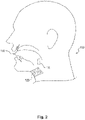
- Figure 2 illustrates an exemplary embodiment of a neuromodulation system for delivering energy in a patient 100 with OSA.
- the system may include an external unit 120 that may be configured for location external to the patient.
- external unit 120 may be configured to be affixed to the patient 100.
- Figure 2 illustrates that in a patient 100 with OSA, the external unit 120 may be configured for placement underneath the patient's chin (e.g., in a location where the external unit in on a side of the patient's skin opposite to a location of terminal fibers of the hypoglossal nerve) and/or on the front of patient's neck.
- the suitability of placement locations may be determined by communication between external unit 120 and implant unit 110, discussed in greater detail below.
- the external unit may be configured to be affixed anywhere suitable on a patient, such as the back of a patient's neck, i.e. for communication with a migraine treatment implant unit, on the outer portion of a patient's abdomen, i.e. for communication with a stomach modulating implant unit, on a patient's back, i.e. for communication with a renal artery modulating implant unit, and/or on any other suitable external location on a patient's skin, depending on the requirements of a particular application.
- a patient such as the back of a patient's neck, i.e. for communication with a migraine treatment implant unit, on the outer portion of a patient's abdomen, i.e. for communication with a stomach modulating implant unit, on a patient's back, i.e. for communication with a renal artery modulating implant unit, and/or on any other suitable external location on a patient's skin, depending on the requirements of a particular application.
- External unit 120 may further be configured to be affixed to an alternative location proximate to the patient.
- the external unit may be configured to fixedly or removably adhere to a strap or a band that may be configured to wrap around a part of a patient's body.
- the external unit may be configured to remain in a desired location external to the patient's body without adhering to that location.
- the external unit 120 may include a housing.
- the housing may include any suitable container configured for retaining components.
- the housing may be any suitable size and/or shape and may be rigid or flexible.
- Non-limiting examples of housings for the external unit 100 include one or more of patches, buttons, or other receptacles having varying shapes and dimensions and constructed of any suitable material.
- the housing may include a flexible material such that the external unit may be configured to conform to a desired location.
- the external unit may include a skin patch, which, in turn, may include a flexible substrate.
- the material of the flexible substrate may include, but is not limited to, plastic, silicone, woven natural fibers, and other suitable polymers, copolymers, and combinations thereof. Any portion of external unit 120 may be flexible or rigid, depending on the requirements of a particular application.
- external unit 120 may be configured to adhere to a desired location.
- at least one side of the housing may include an adhesive material.
- the adhesive material may include a biocompatible material and may allow for a patient to adhere the external unit to the desired location and remove the external unit upon completion of use.
- the adhesive may be configured for single or multiple uses of the external unit. Suitable adhesive materials may include, but are not limited to biocompatible glues, starches, elastomers, thermoplastics, and emulsions.
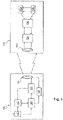
- Figure 3 schematically illustrates a system including external unit 120 and an implant unit 110.
- internal unit 110 may be configured as a unit to be implanted into the body of a patient
- external unit 120 may be configured to send signals to and/or receive signals from implant unit 110.
- various components may be included within a housing of external unit 120 or otherwise associated with external unit 120.
- at least one processor 144 may be associated with external unit 120.
- the at least one processor 144 may be located within the housing of external unit 120.
- the at least one processor may be configured for wired or wireless communication with the external unit from a location external to the housing.
- the at least one processor may include any electric circuit that may be configured to perform a logic operation on at least one input variable.
- the at least one processor may therefore include one or more integrated circuits, microchips, microcontrollers, and microprocessors, which may be all or part of a central processing unit (CPU), a digital signal processor (DSP), a field programmable gate array (FPGA), or any other circuit known to those skilled in the art that may be suitable for executing instructions or performing logic operations.
- CPU central processing unit
- DSP digital signal processor
- FPGA field programmable gate array
- Figure 3 illustrates that the external unit 120 may further be associated with a power source 140.
- the power source may be removably coupled to the external unit at an exterior location relative to external unit.
- power source 140 may be permanently or removably coupled to a location within external unit 120.
- the power source may further include any suitable source of power configured to be in electrical communication with the processor.
- the power source 140 may include a battery.
- the power source may be configured to power various components within the external unit. As illustrated in Figure 3 , power source 140 may be configured to provide power to the processor 144. In addition, the power source 140 may be configured to provide power to a signal source 142.
- the signal source 142 may be in communication with the processor 144 and may include any device configured to generate a signal (e.g., a sinusoidal signal, square wave, triangle wave, microwave, radio-frequency (RF) signal, or any other type of electromagnetic signal).
- Signal source 142 may include, but is not limited to, a waveform generator that may be configured to generate alternating current (AC) signals and/or direct current (DC) signals. In one embodiment, for example, signal source 142 may be configured to generate an AC signal for transmission to one or more other components.
- Signal source 142 may be configured to generate a signal of any suitable frequency. In some embodiments, signal source 142 may be configured to generate a signal having a frequency of from about 6.5 MHz to about 13.6 MHz. In additional embodiments, signal source 142 may be configured to generate a signal having a frequency of from about 7.4 to about 8.8 MHz. In further embodiments, signal source 142 may generate a signal having a frequency as low as 90 kHz or as high as 28 MHz.
- Signal source 142 may be configured for direct or indirect electrical communication with an amplifier 146.
- the amplifier may include any suitable device configured to amplify one or more signals generated from signal source 142.
- Amplifier 146 may include one or more of various types of amplification devices, including, for example, transistor based devices, operational amplifiers, RF amplifiers, power amplifiers, or any other type of device that can increase the gain associated one or more aspects of a signal.
- the amplifier may further be configured to output the amplified signals to one or more components within external unit 120.
- the external unit may additionally include a primary antenna 150.
- the primary antenna may be configured as part of a circuit within external unit 120 and may be coupled either directly or indirectly to various components in external unit 120.
- primary antenna 150 may be configured for communication with the amplifier 146.
- the primary antenna may include any conductive structure that may be configured to create an electromagnetic field.
- the primary antenna may further be of any suitable size, shape, and/or configuration. The size, shape, and/or configuration may be determined by the size of the patient, the placement location of the implant unit, the size and/or shape of the implant unit, the amount of energy required to modulate a nerve, a location of a nerve to be modulated, the type of receiving electronics present on the implant unit, etc.
- the primary antenna may include any suitable antenna known to those skilled in the art that may be configured to send and/or receive signals. Suitable antennas may include, but are not limited to, a long-wire antenna, a patch antenna, a helical antenna, etc.
- primary antenna 150 may include a coil antenna.
- a coil antenna may be made from any suitable conductive material and may be configured to include any suitable arrangement of conductive coils (e.g., diameter, number of coils, layout of coils, etc.).
- a coil antenna suitable for use as primary antenna 150 may have a diameter of between about 1 cm and 10 cm, and may be circular or oval shaped. In some embodiments, a coil antenna may have a diameter between 5 cm and 7 cm, and may be oval shaped.
- a coil antenna suitable for use as primary antenna 150 may have any number of windings, e.g. 4, 8, 12, or more.
- a coil antenna suitable for use as primary antenna 150 may have a wire diameter between about 0.1 mm and 2 mm.
- implant unit 110 may be configured to be implanted in a patient's body (e.g., beneath the patient's skin).
- Figure 2 illustrates that the implant unit 110 may be configured to be implanted for modulation of a nerve associated with a muscle of the subject's tongue 130.
- implant unit 110 may be configured to modulate a hypoglossal nerve of a subject, e.g., through interaction with terminal fibers of the hypoglossal nerve.
- Modulating a nerve associated with a muscle of the subject's tongue 130 may include stimulation to cause a muscle contraction.
- the implant unit may be configured to be placed in conjunction with any nerve that one may desire to modulate.
- modulation of the occipital nerve, the greater occipital nerve, and/or the trigeminal nerve may be useful for treating pain sensation in the head, such as that from migraines.
- Modulation of parasympathetic nerve fibers on and around the renal arteries (i.e.. the renal nerves), the vagus nerve, and /or the glossopharyngeal nerve may be useful for treating hypertension.
- any nerve of the peripheral nervous system both spinal and cranial), including motor neurons, sensory neurons, sympathetic neurons and parasympathetic neurons, may be modulated to achieve a desired effect.
- Implant unit 110 may be formed of any materials suitable for implantation into the body of a patient.
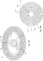
- implant unit 110 may include a flexible carrier 161 ( Figure 4 ) including a flexible, biocompatible material.
- Such materials may include, for example, silicone, polyimides, phenyltrimethoxysilane (PTMS), polymethyl methacrylate (PMMA), Parylene C, polyimide, liquid polyimide, laminated polyimide, black epoxy, polyether ether ketone (PEEK), Liquid Crystal Polymer (LCP), Kapton, etc.
- Implant unit 110 may further include circuitry including conductive materials, such as gold, platinum, titanium, or any other biocompatible conductive material or combination of materials.
- Implant unit 110 and flexible carrier 161 may also be fabricated with a thickness suitable for implantation under a patient's skin. Implant 110 may have thickness of less than about 4 mm or less than about 2 mm.
- implant unit 110 may include a secondary antenna 152 mounted onto or integrated with flexible carrier 161. Similar to the primary antenna, the secondary antenna may include any suitable antenna known to those skilled in the art that may be configured to send and/or receive signals.
- the secondary antenna may include any suitable size, shape, and/or configuration. The size, shape and/or configuration may be determined by the size of the patient, the placement location of the implant unit, the amount of energy required to modulate the nerve, etc. Suitable antennas may include, but are not limited to, a long-wire antenna, a patch antenna, a helical antenna, etc.
- secondary antenna 152 may include a coil antenna having a circular shape (see also Figure 4 ) or oval shape.
- a coil antenna may be made from any suitable conductive material and may be configured to include any suitable arrangement of conductive coils (e.g., diameter, number of coils, layout of coils, etc.).
- a coil antenna suitable for use as secondary antenna 152 may have a diameter of between about 5 mm and 30 mm, and may be circular or oval shaped.
- a coil antenna suitable for use as secondary antenna 152 may have any number of windings, e.g. 4, 15, 20, 30, or 50.
- a coil antenna suitable for use as secondary antenna 152 may have a wire diameter between about 0.01 mm and 1 mm.
- Figs. 10a and 10b illustrate an exemplary double-layer crossover antenna 1101 suitable for use as either primary antenna 150 or secondary antenna 152. While a double-layer crossover antenna is shown and described, other antenna configurations may be suitable for primary antenna 150 and/or secondary antenna 152. For example, single layer antennas may be used where antenna components (e.g., coils) are arranged in a single layer, e.g., either on or within a dielectric or insulating material. Also, while a crossover pattern is shown, other patterns may also be suitable. For example, in some embodiments, a wire associated with primary antenna 150 and/or secondary antenna 152 may include a pattern of traces of progressively decreasing dimension. In the case of traces arranged in coils, for example, each loop could include rings of progressively decreasing diameter to create a pattern that spirals inwardly. A similar approach may be viable using traces of other shapes as well.
- antenna components e.g., coils
- a crossover pattern is shown, other patterns may also be suitable.
- FIG. 10a this figure illustrates a single coil of double-layer crossover antenna 1101, while Figure 10b illustrates two layers of double layer crossover antenna 1101.
- Antenna 1101 may include a first coil of wire 1102 arranged on a first side of a dielectric carrier 1104 and a second coil of wire 1103 on a second side of a dielectric carrier 1104.
- Arranging the antenna coils in a double layer may serve to increase the transmission range of the antenna without increasing the size of the antenna. Such an arrangement, however, may also serve to increase capacitance between the wires of each coil.
- an amount of parasitic capacitance between wires may partially depend on the distance each wire is from its neighbor.
- capacitance may be generated between each loop of the coil and its neighbors to either side. Thus, more compact coils may generate more parasitic capacitance,.
- additional capacitance may then be generated between the wires of the first coil and the wires of the second coil.
- This additional capacitance may be further increased if corresponding loops of the first and second coils have the same or similar diameters, and/or if a dielectric carrier separating the loops is made very thin.
- Increased parasitic capacitance in an antenna may serve to alter characteristics, such as resonant frequency, of the antenna in unpredictable amounts based on manufacturing specifications. Additionally, resonant frequency drift, caused, for example by moisture incursion or antenna flexing, may be increased by the presence of increased parasitic capacitance. Thus, in order to decrease variability in the manufactured product, it may be advantageous to reduce the levels of parasitic capacitance in a dual layer antenna.
- Figure 10b illustrates a double layer crossover antenna 1101 which may serve to reduce the parasitic capacitance in a manufactured antenna.
- a first coil of wire 1102 is concentrically offset from a second coil of wire 1103.
- concentrically offsetting corresponding loops of each wire coil serves to increase the distance between a single loop of the first coil 1102 with a corresponding loop of the second coil 1103. This increased distance, in turn, may decrease the parasitic wire-to-wire capacitance between loops of first coil 1102 and corresponding loops of second coil 1103.
- This configuration may be particularly advantageous in reducing parasitic capacitance in a situation where a dielectric carrier 1104 is thin enough such that the concentric distance by which each coil is offset is relatively large compared to the thickness of the dielectric carrier 1104.
- a concentric offset of 0.5 mm or more may produce a large change in parasitic capacitance.
- a concentric offset of 0.5 mm may produce a smaller change in parasitic capacitance.
- the concentric offset between a first coil 1102 and a second coil 1103 may be achieved, for example, by a plurality of electrical trace steps 1105 that offset each loop of the coils from each preceding loop. Electrical trace steps 1105 on a first side of dielectric carrier 1104 cross over electrical trace steps 1105 on a second side of dielectric carrier 1104, thus providing the crossover feature of double-layer crossover antenna 1101.
- double layer crossover antenna 1101 may include openings 1106 in dielectric carrier 1104 to facilitate the electrical connection of first and second coils 1102, 1103.
- First and second coils 1102, 1103 of double layer crossover antenna 1101 may also include exposed electrical portions 1108 configured to electrically connect with a connector of a device housing that may be coupled to antenna 1101.
- Exposed electrical portions 1108 may be configured so as to maintain electrical contact with the connector of a device housing independent of the axial orientation of the connection. As shown in Figure 10a , for example, exposed electrical portions 1108 may be configured as continuous or discontinuous circles in order to achieve this.
- a first exposed electrical portion 1108 configured as a discontinuous circle may provide a space through which an electrical trace may pass without contacting the first exposed electrical portion, for example to connect with a second exposed electrical portion located inside the first, or to other components located within the circle of the first exposed electrical portion 1108.
- Figure 10a illustrates an antenna having substantially elliptical coils; other shapes, such as circular, triangular, square, etc., may be also be used in different embodiments.
- Elliptical coils may facilitate placement of external unit 120 in certain areas (e.g., under the chin of a subject) while maintaining desirable electrical performance characteristics.
- FIGs 11a and 11 b illustrate an exemplary embodiment of external unit 120, including features that may be found in any combination in other embodiments.
- Figure 11a illustrates a side view of external unit 120, depicting carrier 1201 and electronics housing 1202.
- Carrier 1201 may include a skin patch configured for adherence to the skin of a subject, for example through adhesives of mechanical means.
- Carrier 1201 may be flexible or rigid, or may have flexible portions and rigid portions.
- Carrier 1201 and may include a primary antenna 150, for example, a double-layer crossover antenna 1101 such as that illustrated in Figs. 10a and 10b .
- Carrier 1201 may also include power source 140, such as a paper battery, thin film battery, or other type of substantially flat and/or flexible battery.
- Carrier 1201 may also include any other type of battery or power source.
- Carrier 1201 may also include a connector 1203 configured for selectively or removably connecting carrier 1201 to electronics housing 1202. Connector 1203 may extend or protrude from carrier 1201.
- Connector 1203 may be configured to be received by a recess 1204 of electronics housing 1202
- Connector 1203 may be configured as a non-pouch connector, configured to provide a selective connection to electronics housing 1204 without the substantial use of concave feature .
- Connector 1203 may include, for example a peg, and may have flexible arms.
- Connector 1203 may further include a magnetic connection, a velcro connection, and/or a snap dome connection.
- Connector 1203 may also include a locating feature, configured to locate electronics housing 1202 at a specific height, axial location, and/or axial orientation with respect to carrier 1201.
- a locating feature of connector 1203 may further include pegs, rings, boxes, ellipses, bumps, etc.
- Connector 1203 may be centered on carrier 1201, may be offset from the center by a predetermined amount, or may be provided at any other suitable location of carrier 1201. Multiple connectors 1203 may be provided on carrier 1201. Connector 1203 may be configured such that removal from electronics housing 1202 causes breakage of connector 1203. Such a feature may be desirable to prevent reuse of carrier 1201, which may lose some efficacy through continued use.
- Electronics housing 1202 is illustrated in side view in Figure 11a and in a bottom view in Figure 11b .
- Electronics housing 1202 may include electronics portion 1205, which may be arranged inside electronics housing 1202 in any manner that is suitable.
- Electronics portion 1205 may include various components, further discussed below, of external unit 120.
- electronics portion 1205 may include any combination of at least one processor 144 associated with external unit 120, a power source 140, such as a battery, a primary antenna 152, and an electrical circuit 170.
- Electronics portion 1205 may also include any other component described herein as associated with external unit 120. Additional components may also be recognized by those of skill in the art.
- Electronics housing 1202 may include a recess 1204 configured to receive connector 1203.
- Electronics housing 1202 may include at least one electrical connector 1210, 1211, 1212.
- Electrical connectors 1210, 1211, 1212 may be arranged with pairs of electrical contacts, as shown in Figure 11b , or with any other number of electrical contacts.
- the pair of electrical contacts of each electrical connector 1210, 1211, 1212 may be continuously electrically connected with each other inside of housing 1202, such that the pair of electrical contacts represents a single connection point to a circuit. In such a configuration, it is only necessary that one of the electrical contacts within a pair be connected.
- Electrical connectors 1210, 1211, and 1212 may thus include redundant electrical contacts.
- each electrical connector 1210, 1211, 1212 may also represent opposite ends of a circuit, for example, the positive and negative ends of a battery charging circuit.
- electrical connectors 1210, 1211, and 1212 are configured so as to maintain electrical contact with an exposed electrical portion 1108 independent of an axial orientation of electronics housing 1202. Connection between any or all of electrical connectors 1210, 1211, 1212 and exposed electrical portions 1108 may thus be established and maintained irrespective of relative axial positions of carrier 1201 and housing 1202. Thus, when connector 1203 is received by recess 1204, housing 1202 may rotate with respect to carrier 1201 without interrupting electrical contact between at least one of electrical connectors 1210, 1211, 1212 and exposed electrical portions 1108.
- Axial orientation independence may be achieved, for example, through the use of circular exposed electrical portions 1108 and each of a pair of contacts of electrical connectors 1210, 1211, 1212 disposed equidistant from a center of recess 1204 at a radius approximately equal to that of a corresponding exposed electrical portion 1108.
- exposed electrical portion 1108 includes a discontinuous circle, at least one electrical contact of electrical connectors 1210, 1211, and 1212 may make contact.
- electrical connectors 1210, 1211, 1212 are illustrated as pairs of rectangular electrical contacts. Electrical connectors 1210, 1211, 1212, however, may include any number of contacts, be configured as continuous or discontinuous circles, or have any other suitable shape or configuration.
- electronics housing 1202 may include more electrical connectors 1210, 1211, 1212, than a carrier 1201 includes exposed electrical portions 1108.
- electronics housing 1202 includes three electrical connectors 1210, 1211, and 1212, while a double-layer crossover antenna 1101 includes two exposed electrical portions 1108.
- two electrical connectors 1211 and 1212 may be configured with continuously electrically connected electrical contacts, such that each connector makes contact with a different exposed electrical portion 1108, where the exposed electrical portions 1108 represent opposite ends of double layer crossover antenna 1101.
- antenna 1101 may be electrically connected to the electrical components contained in electronics portion 1205.
- electrical connectors 1210 may not make contact with any electrodes.
- electrical connectors 1210 may be reserved to function as opposite ends of a battery charging circuit, in order to charge a battery contained in electronics portion 1205 when electronics housing 1202 is not being used for therapy.
- a battery charger unit may be provided with a non-breakable connector similar to that of non-pouch connector 1203, and configured to engage with recess 1204. Upon engaging with recess 1204, electrode contacts of the battery charger unit may contact electrical connectors 1210 to charge a battery contained within electronics portion 1205.
- an activator chip may include electronics housing 1202.
- Processor 144 may be configured to activate when at least one of electrical connectors 1210, 1211, 1212 contact exposed electrical portions 1108 included in carrier 1201. In this manner, an electronics housing 1202 may be charged and left dormant for many days prior to activation. Simply connecting electronics housing 1202 to carrier 1201 (and inducing contact between an electrical connector 1210, 1211, 1212 and an electrode portion 1108) may cause the processor to activate.
- processor 144 may be configured to enter a specific mode of operation, such as a calibration mode (for calibrating the processor after placement of the carrier on the skin), a placement mode (for assisting a user to properly place the carrier on the skin), and/or a therapy mode (to begin a therapy session).
- the various modes of processor 144 may include waiting periods at the beginning, end, or at any time during.
- a placement mode may include a waiting period at the end of the mode to provide a period during which a subject may fall asleep.
- a therapy mode may include a similar waiting period at the beginning of the mode.
- processor 144 may be configured to provide waiting periods separate from the described modes, in order to provide a desired temporal spacing between system activities.
- Implant unit 110 may additionally include a plurality of field-generating implant electrodes 158a, 158b.
- the electrodes may include any suitable shape and/or orientation on the implant unit so long as the electrodes may be configured to generate an electric field in the body of a patient.
- Implant electrodes 158a and 158b may also include any suitable conductive material (e.g., copper, silver, gold, platinum, iridium, platinum-iridium, platinum-gold, conductive polymers, etc.) or combinations of conductive (and/or noble metals) materials.
- the electrodes may include short line electrodes, circular electrodes, and/or circular pairs of electrodes.
- electrodes 158a and 158b may be located on an end of a first extension 162a of an elongate arm 162.
- the electrodes may be located on any portion of implant unit 110.
- implant unit 110 may include electrodes located at a plurality of locations, for example on an end of both a first extension 162a and a second extension 162b of elongate arm 162, as illustrated, for example, in Figure 5 .
- Implant electrodes may have a thickness between about 200 nanometers and 1 millimeter.
- Anode and cathode electrode pairs may be spaced apart by about a distance of about 0.2 mm to 25 mm.
- anode and cathode electrode pairs may be spaced apart by a distance of about 1 mm to 10 mm, or between 4 mm and 7 mm.
- Adjacent anodes or adjacent cathodes may be spaced apart by distances as small as 0.001 mm or less, or as great as 25 mm or more. In some embodiments, adjacent anodes or adjacent cathodes may be spaced apart by a distance between about 0.2 mm and 1 mm.
- Figure 4 provides a schematic representation of an exemplary configuration of implant unit 110.
- the field-generating electrodes 158a and 158b may include two sets of four circular electrodes, provided on flexible carrier 161, with one set of electrodes providing an anode and the other set of electrodes providing a cathode.
- Implant unit 110 may include one or more structural elements to facilitate implantation of implant unit 110 into the body of a patient. Such elements may include, for example, elongated arms, suture holes, polymeric surgical mesh, biological glue, spikes of flexible carrier protruding to anchor to the tissue, spikes of additional biocompatible material for the same purpose, etc.
- implant unit 110 may include an elongate arm 162 having a first extension 162a and, optionally, a second extension 162b. Extensions 162a and 162b may aid in orienting implant unit 110 with respect to a particular muscle (e.g., the genioglossus muscle), a nerve within a patients body, or a surface within a body above a nerve.
- a particular muscle e.g., the genioglossus muscle
- first and second extensions 162a, 162b may be configured to enable the implant unit to conform at least partially around soft or hard tissue (e.g., nerve, bone, or muscle, etc.) beneath a patient's skin.
- implant unit 110 may also include one or more suture holes 160 located anywhere on flexible carrier 161.
- suture holes 160 may be placed on second extension 162b of elongate arm 162 and/or on first extension 162a of elongate arm 162.
- Implant unit 110 may be constructed in various shapes. Additionally, or alternatively, implant unit 110 may include surgical mesh 1050 or other perforatable material. In some embodiments, implant unit may appear substantially as illustrated in Figure 4 .
- implant unit 110 may lack illustrated structures such as second extension 162b, or may have additional or different structures in different orientations. Additionally, implant unit 110 may be formed with a generally triangular, circular, or rectangular shape, as an alternative to the winged shape shown in Figure 4 . In some embodiments, the shape of implant unit 110 (e.g., as shown in Figure 4 ) may facilitate orientation of implant unit 110 with respect to a particular nerve to be modulated. Thus, other regular or irregular shapes may be adopted in order to facilitate implantation in differing parts of the body.
- implant unit 110 may include a protective coating that encapsulates implant unit 110.
- the protective coating may be made from a flexible material to enable bending along with flexible carrier 161.
- the encapsulation material of the protective coating may also resist humidity penetration and protect against corrosion.
- the protective coating may include a plurality of layers, including different materials or combinations of materials in different layers
- FIG. 5 is a perspective view of an alternate embodiment of an implant unit 110, according to an exemplary embodiment of the present disclosure.
- implant unit 110 may include a plurality of electrodes, located, for example, at the ends of first extension 162a and second extension 162b.
- Figure 5 illustrates an embodiment wherein implant electrodes 158a and 158b include short line electrodes.
- external unit 120 may be configured to communicate with implant unit 110.
- a primary signal may be generated on primary antenna 150, using, e.g., processor 144, signal source 142, and amplifier 146.
- power source 140 may be configured to provide power to one or both of the processor 144 and the signal source 142.
- the processor 144 may be configured to cause signal source 142 to generate a signal (e.g., an RF energy signal).
- Signal source 142 may be configured to output the generated signal to amplifier 146, which may amplify the signal generated by signal source 142. The amount of amplification and, therefore, the amplitude of the signal may be controlled, for example, by processor 144.
- the amount of gain or amplification that processor 144 causes amplifier 146 to apply to the signal may depend on a variety of factors, including, but not limited to, the shape, size, and/or configuration of primary antenna 150, the size of the patient, the location of implant unit 110 in the patient, the shape, size, and/or configuration of secondary antenna 152, a degree of coupling between primary antenna 150 and secondary antenna 152 (discussed further below), a desired magnitude of electric field to be generated by implant electrodes 158a, 158b, etc.
- Amplifier 146 may output the amplified signal to primary antenna 150.
- External unit 120 may communicate a primary signal on primary antenna to the secondary antenna 152 of implant unit 110. This communication may result from coupling between primary antenna 150 and secondary antenna 152. Such coupling of the primary antenna and the secondary antenna may include any interaction between the primary antenna and the secondary antenna that causes a signal on the secondary antenna in response to a signal applied to the primary antenna. In some embodiments, coupling between the primary and secondary antennas may include capacitive coupling, inductive coupling, radiofrequency coupling, etc. and any combinations thereof.
- Coupling between primary antenna 150 and secondary antenna 152 may depend on the proximity of the primary antenna relative to the secondary antenna. That is, in some embodiments, an efficiency or degree of coupling between primary antenna 150 and secondary antenna 152 may depend on the proximity of the primary antenna to the secondary antenna.
- the proximity of the primary and secondary antennas may be expressed in terms of a coaxial offset (e.g., a distance between the primary and secondary antennas when central axes of the primary and secondary antennas are co-aligned), a lateral offset (e.g., a distance between a central axis of the primary antenna and a central axis of the secondary antenna), and/or an angular offset (e.g., an angular difference between the central axes of the primary and secondary antennas).
- a coaxial offset e.g., a distance between the primary and secondary antennas when central axes of the primary and secondary antennas are co-aligned
- lateral offset e.g., a distance between a central axis
- a theoretical maximum efficiency of coupling may exist between primary antenna 150 and secondary antenna 152 when both the coaxial offset, the lateral offset, and the angular offset are zero. Increasing any of the coaxial offset, the lateral offset, and the angular offset may have the effect of reducing the efficiency or degree of coupling between primary antenna 150 and secondary antenna 152.
- a secondary signal may arise on secondary antenna 152 when the primary signal is present on the primary antenna 150.
- Such coupling may include inductive/magnetic coupling, RF coupling/transmission, capacitive coupling, or any other mechanism where a secondary signal may be generated on secondary antenna 152 in response to a primary signal generated on primary antenna 150.
- Coupling may refer to any interaction between the primary and secondary antennas.
- circuit components associated with implant unit 110 may also affect the secondary signal on secondary antenna 152.
- the secondary signal on secondary antenna 152 may refer to any and all signals and signal components present on secondary antenna 152 regardless of the source.
- a signal on primary antenna 150 induced by a secondary signal on secondary antenna 152 may be referred to as a primary coupled signal component.
- the primary signal may refer to any and all signals or signal components present on primary antenna 150, regardless of source, and the primary coupled signal component may refer to any signal or signal component arising on the primary antenna as a result of coupling with signals present on secondary antenna 152.
- the primary coupled signal component may contribute to the primary signal on primary antenna 150.
- Implant unit 110 may be configured to respond to external unit 120.
- a primary signal generated on primary coil 150 may cause a secondary signal on secondary antenna 152, which in turn, may cause one or more responses by implant unit 110.
- the response of implant unit 110 may include the generation of an electric field between implant electrodes 158a and 158b.
- Figure 6 illustrates circuitry 170 that may be included in external unit 120 and circuitry 180 that may be included in implant unit 110. Additional, different, or fewer circuit components may be included in either or both of circuitry 170 and circuitry 180.
- secondary antenna 152 may be arranged in electrical communication with implant electrodes 158a, 158b.
- circuitry connecting secondary antenna 152 with implant electrodes 158a and 158b may cause a voltage potential across implant electrodes 158a and 158b in the presence of a secondary signal on secondary antenna 152.
- This voltage potential may be referred to as a field inducing signal, as this voltage potential may generate an electric field between implant electrodes 158a and 158b.
- the field inducing signal may include any signal (e.g., voltage potential) applied to electrodes associated with the implant unit that may result in an electric field being generated between the electrodes.
- Energy transfer between primary antenna 150 and secondary antenna 152 via the primary signal may be improved when a resonant frequency of primary antenna 150 and its associated circuitry 170 matches that of secondary antenna 152 and its associated circuitry 180.
- a resonant frequency match between two antennas may be characterized by the proximity of two resonant frequencies to one another. For example, a resonant frequency match may be considered to occur when two resonant frequencies are within 30%, 20%, 10%, 5%, 3%, 1%, 0.5%, 0.1%, or less of each other. Accordingly, a resonant frequency mismatch may be considered to occur when two resonant frequencies do not match.
- a resonant frequency match between two antennas may also be characterized by the efficiency of energy transfer between the antennas.
- the efficiency of energy transfer between two antennas may depend on several factors, one of which may be the degree to which the resonant frequencies of the antennas match. Thus, if all other factors are held constant, changing the resonant frequency of one antenna with respect to the other will alter the efficiency of energy transfer.
- a resonant frequency match between two antennas may be considered to occur when the efficiency of energy transfer is within 50% or greater of a maximum energy transfer when all other factors remain constant.
- a resonant frequency match may require energy transfer efficiencies of 60%, 70%, 80%, 90%, 95% or greater.
- a resonant frequency of the implant unit 110 may drift after implantation. Other factors present during implantation may also influence the frequency drift of implant unit 110 after implantation. This drifting of the resonant frequency may last for several days to several months after implantation before stabilizing. For example, the resonant frequency of an implant unit 110 may drift from 8.1 kHz to 7.9 kHz.
- an implant unit 110 may be manufactured with a resonant frequency value of 8.1 kHz prior to implantation.
- Resonant frequency values of manufactured implant units 110 may be adjusted during the manufacturing process through the use of at least one trimming capacitor.
- a carrier 161 may be manufactured with all or some of the components of the final implant unit, including, for example, secondary antenna 152, implant circuitry 180, modulation electrodes 158a, 158b. The resonant frequency of this assembly may then be measured or otherwise determined. Due to variations in manufacturing processes and materials, the resonant frequency of each manufactured unit may differ. Thus, in order to meet a specific resonance frequency, each implant unit may be adjusted through the addition of one or more trimming capacitors to the implant circuitry 180 prior to encapsulation. In one embodiment, a capacitor may be laser trimmed to a predetermined capacitance value before insertion into implant circuitry 180.
- a stock capacitor of known value may be inserted into implant circuitry 180.
- a plurality of capacitors may be inserted into implanted circuitry 180 to appropriately adjust the resonant frequency of implant unit 110.
- Such a plurality of capacitors may include a series of capacitors having progressively smaller capacitance values, and a resonant frequency of the assembly may be measured after the insertion of each capacitor prior to choosing and inserting the next.
- implantable circuit 180 may include at least one capacitor configured to create a predetermined mismatch between a resonant frequency of implantable circuit 180 and external circuit 170.
- a resonant frequency of primary antenna 152 may vary temporally due, for example, to changing environmental conditions.
- the application of the antenna 152 to the skin of a subject may cause bending of the primary antenna 152 to conform to the skin of a subject. Such bending may cause a shift in the spatial relationship among coils within primary antenna 152, which may lead to a change in resonant frequency.
- Other factors associated, e.g., with the condition of the subject's skin e.g., moisture, sweat, oil, hair, etc.
- the temporal variance in resonant frequency of primary antenna may be between 0-5%, up to 10%, or up to 20% or more.
- a current resonant frequency of the primary antenna 152 e.g., a resonant frequency exhibited by the primary antenna or a circuit including the primary antenna at a particular point in time or over a time duration
- Processor 144 of the external unit may be configured to determine a resonant frequency mismatch between an external circuit 170 associated with primary antenna 152 and an implantable circuit 180 associated with secondary antenna 150 and adjust a resonant frequency of the external circuit 170 associated with primary antenna 152 in order to reduce or eliminate the resonant frequency mismatch.
- processor 144 may be configured to determine a resonant frequency mismatch based on a primary coupled signal component present on the primary antenna due coupling between primary antenna 152 and secondary antenna 150.
- Monitoring a primary coupled signal component by the processor 144 may provide an indication of transmission efficiency, which may in turn be an indication of resonant frequency mismatch.
- the primary coupled signal component and the interaction between primary antenna 152 and secondary antenna 150 are explained in greater detail below.
- processor 144 may adjust the resonant frequency of the external circuit 170 to reduce the mismatch.
- a resonance matching unit 190 may be in electrical communication with the external circuit 170 to facilitate the alteration of the resonant frequency of the external circuit 170.
- the circuit formed between the external circuit 170 and the resonance matching unit 190 may include an adjustable resonance circuit 191. Such alteration may be performed, for example, through the selective inclusion or exclusion of at least one capacitor into or out of the adjustable resonance circuit 191 formed between the external circuit 170 and the resonance matching unit 190.
- Resonance matching unit 190 may cause a change in the resonant frequency of the adjustable resonance circuit 191.
- Resonance matching unit 190 may be provided with one or more trim capacitors configured, through processor 144 controlled switches, for selective inclusion and exclusion.
- the switches may include, for example, transistors or relays.
- processor 144 may include or exclude a capacitor adjustable resonance circuit 191 by opening or closing a switch associated with the respective capacitor. Providing a single capacitor, therefore, permits processor 144 to switch the resonant frequency of the adjustable resonance circuit 191 between two different values.
- a bank of six capacitors may be provided, permitting processor 144 to switch the resonant frequency of the adjustable resonance circuit 191 between 64 (i.e., 2 6 ) different values.
- 64 i.e., 2 6
- more or fewer capacitors may be provided for adjusting the resonant frequency of the adjustable resonance circuit 191 to reduce the mismatch.
- processor 144 may be configured to switch capacitors from a capacitor bank into and out of the adjustable resonance circuit 191 during transmission of a primary signal to determine a capacitor combination that changes (e.g., increases) transmission efficiency and resonant frequency match. In some embodiments, processor 144 may be configured to select an optimal combination of capacitors to provide a best resonant frequency match. In some embodiments, processor 144 may be configured to select an optimal combination of capacitors, based on a detected magnitude of the power transmitted to the implant unit. In alternative embodiments, processor 144 may be configured to select a combination of capacitors that provides a resonant frequency match surpassing a predetermined threshold, regardless of whether such combination produces an optimal resonant frequency match.
- Resonant frequency matching between a primary antenna 150 and a secondary antenna 152 may increase the efficiency of energy transfer between the antennas.
- external unit 120 may be provided with features that may facilitate development of a match between a frequency of a primary signal and a resonant frequency of the external circuit 170 associated with primary antenna 150. Development of such a match may further increase the efficiency of external unit 120.
- Some conventional amplifiers may be configured to generate a signal at a single frequency. Using such an amplifier may create a mismatch between the signal generated by the amplifier and the resonant frequency of the adjustable resonance circuit 191 when the adjustable resonance circuit 191 is adjusted to match frequencies with an implant unit 110.
- self-resonant circuits may be provided for use with a resonance matching unit 190, as further described below with respect to Figures 7 and 8 .
- Figure 7 depicts an embodiment illustrating a self-resonant transmitter circuit employing a modified class D amplifier for use with resonant frequency matching methods.
- Modified class D amplifier 1600 may be used in place of, or in addition to, any or all of the elements of external unit 120 depicted in Figure 3 .
- modified class D amplifier 1600 may replace signal source 142 and amplifier 146.
- processor 144 may be configured to adjust the operation of a class D amplifier to provide a frequency match between a generated signal and a resonant frequency of an adjustable resonance circuit 191.
- Modified class D amplifier 1600 may be used to provide such an adjustment as follows.
- Modified class D amplifier 1600 includes an H bridge 1601 including switches (such as MOSFETs) 1620. Between the switches, an adjustable resonance transmitter circuit 1610 may be provided. Power to the modified class D amplifier may be provided by supply 1650, which may include a battery, for example.
- Adjustable resonance transmitter circuit 1610 may include adjustable resonance circuit 191.
- adjustable resonance transmitter circuit 1610 may include at least a primary antenna 150 and a resonance matching unit 190.
- Figure 7 illustrates an exemplary self-resonant transmitter circuit 1610, depicting multiple capacitances 1640 and inductances 1660.
- resonance matching unit 190 may take the place of some or all of capicitances 1640.
- adjustable resonance transmitter circuit 1610 may include a primary antenna 150, and thus inductance 1660 may include the inductance of antenna 150.
- Capacitances 1640 may include multiple capacitors, combinations of which may be chosen from among trim capacitors as described above, in order to selectively provide an appropriate value of capacitance 1640. The value of capacitance 1640 may be selected for resonant frequency matching to adjustable resonance circuit 191.
- Inductances 1660 may be provided at least partially by primary antenna 150.
- Processor 144 may also adjust a driving frequency of the H bridge switches 1620 in order to generate a signal of a frequency that matches the resonant frequency of self-resonant circuit 1610.
- a driving frequency of the H bridge switches 1620 By selectively opening and closing switches 1620 appropriately, the DC voltage signal of supply 1650 may be converted into a square wave of a selected frequency. This frequency may be selected to match the resonant frequency of adjustable resonance circuit 1610 in order to change (e.g., increase) the efficiency of the circuit.
- FIG 8 depicts an additional embodiment illustrating a pulsed mode self-resonant transmitter 1700 for use with resonant frequency matching methods.
- Pulsed mode self-resonant transmitter 1700 may be used in place of, or in addition to, any or all of the elements of external unit 120 depicted in Figure 3 .
- pulsed mode self-resonant transmitter 1700 may replace signal source 142 and amplifier 146.
- processor 144 may be configured to control the circuit through a power release unit, depicted in the present embodiment as switch 1730.
- a power release unit may include a transistor, relay, or similar switching device.
- Pulsed mode self-resonant transmitter 1700 may include a primary power source 1780, for example, a battery or alternative source of power.
- Transmitter 1700 may include a power storage unit, such as storage capacitor 1750. Other suitable power storage units may also be utilized, such as an inductor and/or battery, as well as combinations of these storage elements. Transmitter 1700 may also include a self-resonant transmitter circuit 1710, including resonance capacitance 1720 and a resonance inductance 1760. Resonance inductance 1760 may be provided at least partially by primary antenna 150.
- a power storage unit such as storage capacitor 1750.
- Other suitable power storage units may also be utilized, such as an inductor and/or battery, as well as combinations of these storage elements.
- Transmitter 1700 may also include a self-resonant transmitter circuit 1710, including resonance capacitance 1720 and a resonance inductance 1760. Resonance inductance 1760 may be provided at least partially by primary antenna 150.
- Transmitter 1700 may operate in the following manner, among others.
- Processor 144 may be configured to control the power release unit, illustrated in Figure 8 as switch 1730.
- Processor 144 may be configured to control a mode of operation of the power release unit such that in a first mode of operation the power storage unit receives power from the power source, and in a second mode of operation, the power storage unit releases power to the antenna to cause an oscillation in the primary antenna at a resonance frequency.
- the power storage unit for example, storage capacitor 1750
- the power storage unit may be configured to store energy from power source 1780.
- switch 1730 When switch 1730 is maintained in an open position, or a first state, current from power source 1780 may flow into storage capacitor 1750 which thereby stores energy by accumulating electrical charge.
- the power release unit may be configured to cause the release a pulse of energy from the power storage unit to primary antenna 150 after the power storage unit has accumulated certain amount electrical charge.
- a second mode of operation when switch 1730 is closed, or moved to a second state, charged storage in capacitor 1750 drives current into the self-resonant circuit 1710 during a current loading period, where energy is stored in inductance 1760. Due to the operation of diode 1770, current flow into circuit 1710 will be cut off after a period of energy accumulation. The current transferred to circuit 1710 will then oscillate freely within circuit 1710 at the resonant frequency of circuit 1710 and thus generate a signal for transmission to the implant through primary antenna 150 (which is included in the circuit and creates at least a portion of inductance 1760).
- the amplitude of the oscillations may diminish at a rate determined by the components of circuit 1710.
- switch 1730 may be closed again to permit storage capacitor 1750 to enter a current loading period again.
- oscillation amplitude may be measured, for example, by processor 144 to determine the appropriate operation of switch 1730.
- a current loading period may be between 0.5 and 10 ⁇ s, or between 2 and 5 ⁇ s.
- a free oscillation period may be between 10 and 30 ⁇ s.
- Switch 1730 may be opened and closed several times in order to maintain a desired level of current flow in circuit 1710 for a desired period of time by assembling a series of current loading period and free oscillation periods.
- the desired period of time may correspond to a sub-pulse of a stimulation control signal, discussed in greater detail below.
- the operation of switch 1730 may be adjusted by processor 144 to increase the efficacy of modulation signals generated in implant unit 110. Such adjustments may be based, for example, on feedback received from implant unit 110, as discussed herein.
- Storage capacitor 1750 may be selected to store enough energy for a complete stimulation sub-pulse, which may be, for example, between 50 and 250 ⁇ s, or between 1 ⁇ s and 2 ms. After delivery of a stimulation sub-pulse, switch 1730 may be closed again in order to permit storage capacitor 1750 to accumulate energy from power source 1780. Such accumulation may occur, for example, over a time period of between 5 and 50 milliseconds. Energy accumulated over this accumulation period may be, for example, between 1 microjoule and 10 millijoules.
- Storage capacitor 1750 may be selected so as to have characteristics permitting the current in circuit 1710 to rise to a desired level at a desired rate.
- the capacitor 1750 may be selected such that the current in circuit 1710 may change rapidly to permit a corresponding rapid increase in transmission power.
- capacitor 1750 may be selected so as to permit the current in circuit 1710 to rise to a desired value, (e.g. between 100 mAmps and 1 Amp) during the current loading period.
- capacitor 1750 may be selected such that a maximum value of current in circuit 1710 is higher than may be possible using power source 1780 alone.
- capacitor 1750 may be selected so as to drive a current in circuit 1710 that is 5, 10, 20, or 100 times greater than may be permitted through the use of power source 1780 alone.
- a battery having a voltage between 3 and 6 volts used as power source 1780 may yield a voltage in circuit 1710 of between 300 and 600 volts.
- Suitable capacitors may be chosen in the range of 1 microfarad to 100 microfarads.
- Circuit 1710 may be configured so as to permit a power storage unit to release a desired portion of its stored energy in a desired time period - i.e. the current loading period as described above.
- circuit 1710 may be configured to permit a power storage unit, such as storage capacitor 1750 to release between 1% and 10% of its accumulated charge in a time period between 1 and 10 microseconds.
- the signal for transmission is generated by the self resonance of circuit 1710, it has a frequency dictated by the resonant frequency of circuit 1710.
- Such an arrangement may offer more efficient transmission than configurations that drive a transmission circuit with a signal that does not match the resonant frequency of the transmission circuit.
- Generating a transmission signal in the manner described may minimize the risk of reductions in energy transfer efficiency caused by changes in resonance of the transmission circuit. As discussed above, such temporal resonance changes in the transmission circuit may range between 0-5%, up to 10%, up to 20% or more.
- Components of transmitter 1700 may be chosen such that the current loading period is approximately two microseconds, and a period of free oscillation in circuit 1710 is between 10 and 20 microseconds. Other components may be selected, however, to provide any desired current loading period or free oscillation period.
- stimulation pulses of varying lengths may be desired. Stimulation pulses of longer than a single period of free oscillation may be constructed by multiple cycles of loading and releasing energy from storage capacitor 1750 into circuit 1710.
- Storage capacitor 1750 may itself be chosen to store enough charge to drive a large number of oscillation cycles (e.g. between 10 and 100) in order to construct entire stimulation pulses without requiring recharging from power source 1780.
- transmitter 1700 may be used in conjunction with resonance matching unit 190.
- a resonant frequency of circuit 1710 may vary.
- Processor 144 may be configured to cause delivery of an impulse of energy to circuit 1710, for example, via operation of a power release unit such as switch 1730. This impulse of energy may excite circuit 1710 and cause oscillations in circuit 1710 at the current resonant frequency of the external circuit such that power is delivered from primary antenna 150 to implant unit 110 at the current resonant frequency of the circuit 1710.
- Resonance matching unit 190 may be in electrical communication (e.g., direct or indirect electrical connection) with circuit 1710, and may be configured, under control of processor 144, to alter the current resonant frequency of the circuit formed by circuit 1710 and matching unit 190. Such alterations of the current resonant frequency may be performed, for example, to optimize transmission efficiency with implant unit 121.
- Pulsed mode self-resonant transmitter 1700 may provide several advantages. As described above, because the transmission signal is generated by the self-resonance of circuit 1710, it likely will match the resonant frequency of circuit 1710, obviating a need to match the frequency of the generated signal with the circuit resonance frequency. Further, because energy is stored in capacitor 1750 prior to discharge into circuit 1710, a greater flexibility in choice of power source 1780 may be provided. Effective neural modulation by an implant unit may depend on current levels that rise rapidly.
- Naturally functioning neurons function by transmitting action potentials along their length.
- neurons include multiple ion channels along their length that serve to maintain a voltage potential gradient across a plasma membrane between the interior and exterior of the neuron.
- Ion channels operate by maintaining an appropriate balance between positively charged sodium ions on one side of the plasma membrane and negatively charged potassium ions on the other side of the plasma membrane.
- a sufficiently high voltage potential difference created near an ion channel may exceed a membrane threshold potential of the ion channel.
- the ion channel may then be induced to activate, pumping the sodium and potassium ions across the plasma membrane to switch places in the vicinity of the activated ion channel. This, in turn, further alters the potential difference in the vicinity of the ion channel, which may serve to activate a neighboring ion channel.
- the cascading activation of adjacent ion channels may serve to propagate an action potential along the length of the neuron. Further, the activation of an ion channel in an individual neuron may induce the activation of ion channels in neighboring neurons that, bundled together, form nerve tissue. The activation of a single ion channel in a single neuron, however, may not be sufficient to induce the cascading activation of neighboring ion channels necessary to permit the propagation of an action potential. Thus, the more ion channels in a locality that may be recruited by an initial potential difference, caused through natural means such as the action of nerve endings or through artificial means, such as the application of electric fields, the more likely the propagation of an action potential may be. The process of artificially inducing the propagation of action potentials along the length of a nerve may be referred to as stimulation, or up modulation.
- Neurons may also be prevented from functioning naturally through constant or substantially constant application of a voltage potential difference.
- each ion channel experiences a refractory period, during which it "resets” the sodium and potassium concentrations across the plasma membrane back to an initial state. Resetting the sodium and potassium concentrations causes the membrane threshold potential to return to an initial state. Until the ion channel restores an appropriate concentration of sodium and potassium across the plasma membrane, the membrane threshold potential will remain elevated, thus requiring a higher voltage potential to cause activation of the ion channel. If the membrane threshold potential is maintained at a high enough level, action potentials propagated by neighboring ion channels may not create a large enough voltage potential difference to surpass the membrane threshold potential and activate the ion channel. Thus, by maintaining a sufficient voltage potential difference in the vicinity of a particular ion channel, that ion channel may serve to block further signal transmission.
- the membrane threshold potential may also be raised without eliciting an initial activation of the ion channel. If an ion channel (or a plurality of ion channels) are subjected to an elevated voltage potential difference that is not high enough to surpass the membrane threshold potential, it may serve to raise the membrane threshold potential over time, thus having a similar effect to an ion channel that has not been permitted to properly restore ion concentrations. Thus, an ion channel may be recruited as a block without actually causing an initial action potential to propagate. This method may be valuable, for example, in pain management, where the propagation of pain signals is undesired.
- Slowly rising current levels in a modulation signal may affect a nerve in a similar fashion. That is, a current level (and thus voltage potential difference) that increases slowly may serve to raise the membrane threshold potential during the application of the modulation signal, thus causing the nerve to require a higher ultimate current level to achieve modulation, which may result in diminished or absent modulation.
- Applying a modulation signal such that the current level (or power level) of the signal increases rapidly or greater than a threshold rate may not give the nerve time to react, and thus may ultimately produce more effective modulation at lower current levels.
- using a slow current ramp or a rate lower than a threshold rate may ultimately require higher levels of current to achieve effective neuromodulation.
- the power transferred to implant unit 110 may be required to increase at a rate that surpasses a power increase threshold rate.
- a battery alone may require a high-voltage and/or high-current battery.
- Such a battery may be expensive and/or difficult to design.
- transmitter 1700 which permits the delivery of a rapidly changing current levels and high peak current levels through the use of a power source incapable of delivering the threshold rate of power increase, such as a relatively low voltage / low current battery.
- a threshold rate of power increase in the implant may include an increase in current flow through the implant from substantially zero current to a current level sufficient for effective modulation (e.g., a current between 200 ⁇ Amps and 3 mAmps) in less than 20 microseconds, less than 10 microseconds, or less than 5 microseconds.
- a threshold rate of power increase may include a current increase between 0.01 - 0.6 milliamps per microsecond.
- a threshold rate of power increase may include a current increase between 0.05 - 0.2 milliamps per microsecond.
- Transmitter 1700 may also offer enhanced efficiency. Transmitter 1700 also may use fewer switches (e.g. transistors) than does a conventional amplifying circuit. Each switch may be a source of energy loss, contributing to an overall less efficient circuit. The presence of a single switch 1730 in transmitter 1700 may increase the efficiency of the circuit as a whole.
- switches e.g. transistors
- the field inducing signal may be generated as a result of conditioning of the secondary signal by circuitry 180.
- circuitry 170 of external unit 120 may be configured to generate an AC primary signal on primary antenna 150 that may cause an AC secondary signal on secondary antenna 152.
- it may be advantageous e.g., in order to generate a unidirectional electric field for modulation of a nerve
- circuitry 180 in implant unit 110 may include an AC-DC converter.
- the AC to DC converter may include any suitable converter known to those skilled in the art.
- the AC-DC converter may include rectification circuit components including, for example, diode 156 and appropriate capacitors and resistors.
- implant unit 110 may include an AC-AC converter, or no converter, in order to provide an AC field inducing signal at implant electrodes 158a and 158b.
- the field inducing signal may be configured to generate an electric field between implant electrodes 158a and 158b.
- the magnitude and/or duration of the generated electric field resulting from the field inducing signal may be sufficient to modulate one or more nerves in the vicinity of electrodes 158a and 158b.
- the field inducing signal may be referred to as a modulation signal.
- the magnitude and/or duration of the field inducing signal may generate an electric field that does not result in nerve modulation. In such cases, the field inducing signal may be referred to as a sub-modulation signal.
- a modulation signal may include a moderate amplitude and moderate duration, while in other embodiments, a modulation signal may include a higher amplitude and a shorter duration.
- Various amplitudes and/or durations of field-inducing signals across electrodes 158a, 158b may result in modulation signals, and whether a field-inducing signal rises to the level of a modulation signal can depend on many factors (e.g., distance from a particular nerve to be stimulated; whether the nerve is branched; orientation of the induced electric field with respect to the nerve; type of tissue present between the electrodes and the nerve; etc.).
- a field inducing signal constitutes a modulation signal (resulting in an electric field that may cause nerve modulation) or a sub-modulation signal (resulting in an electric field not intended to cause nerve modulation) may ultimately be controlled by processor 144 of external unit 120. For example, in certain situations, processor 144 may determine that nerve modulation is appropriate. Under these conditions, processor 144 may cause signal source 144 and amplifier 146 to generate a modulation control signal on primary antenna 150 (i.e., a signal having a magnitude and/or duration selected such that a resulting secondary signal on secondary antenna 152 will provide a modulation signal at implant electrodes 158a and 158b).
- a modulation control signal on primary antenna 150 i.e., a signal having a magnitude and/or duration selected such that a resulting secondary signal on secondary antenna 152 will provide a modulation signal at implant electrodes 158a and 158b.
- Processor 144 may be configured to limit an amount of energy transferred from external unit 120 to implant unit 110.
- implant unit 110 may be associated with a threshold energy limit that may take into account multiple factors associated with the patient and/or the implant. For example, in some cases, certain nerves of a patient should receive no more than a predetermined maximum amount of energy to minimize the risk of damaging the nerves and/or surrounding tissue.
- circuitry 180 of implant unit 110 may include components having a maximum operating voltage or power level that may contribute to a practical threshold energy limit of implant unit 110. Processor 144 may be configured to account for such limitations when setting the magnitude and/or duration of a primary signal to be applied to primary antenna 150.
- processor 144 may also determine a lower power threshold based, at least in part, on an efficacy of the delivered power.
- the lower power threshold may be computed based on a minimum amount of power that enables nerve modulation (e.g., signals having power levels above the lower power threshold may constitute modulation signals while signals having power levels below the lower power threshold may constitute sub-modulation signals).
- a lower power threshold may also be measured or provided in alternative ways.
- appropriate circuitry or sensors in the implant unit 110 may measure a lower power threshold.
- a lower power threshold may be computed or sensed by an additional external device, and subsequently programmed into processor 144, or programmed into implant unit 110.
- implant unit 110 may be constructed with circuitry 180 specifically chosen to generate signals at the electrodes of at least the lower power threshold.
- an antenna of external unit 120 may be adjusted to accommodate or produce a signal corresponding to a specific lower power threshold.
- the lower power threshold may vary from patient to patient, and may take into account multiple factors, such as, for example, modulation characteristics of a particular patient's nerve fibers, a distance between implant unit 110 and external unit 120 after implantation, and the size and configuration of implant unit components (e.g., antenna and implant electrodes), etc.
- Processor 144 may also be configured to cause application of sub-modulation control signals to primary antenna 150.
- Such sub-modulation control signals may include an amplitude and/or duration that result in a sub-modulation signal at electrodes 158a, 158b. While such sub-modulation control signals may not result in nerve modulation, such sub-modulation control signals may enable feedback-based control of the nerve modulation system. That is, in some embodiments, processor 144 may be configured to cause application of a sub-modulation control signal to primary antenna 150. This signal may induce a secondary signal on secondary antenna 152, which, in turn, induces a primary coupled signal component on primary antenna 150.
- external unit 120 may include a feedback circuit 148 (e.g., a signal analyzer or detector, etc.), which may be placed in direct or indirect communication with primary antenna 150 and processor 144.
- Sub-modulation control signals may be applied to primary antenna 150 at any desired periodicity. In some embodiments, the sub-modulation control signals may be applied to primary antenna 150 at a rate of one every five seconds (or longer). In other embodiments, the sub-modulation control signals may be applied more frequently (e.g., once every two seconds, once per second, once per millisecond, once per nanosecond, or multiple times per second). Further, it should be noted that feedback may also be received upon application of modulation control signals to primary antenna 150 (i.e., those that result in nerve modulation), as such modulation control signals may also result in generation of a primary coupled signal component on primary antenna 150.
- the primary coupled signal component may be fed to processor 144 by feedback circuit 148 and may be used as a basis for determining a degree of coupling between primary antenna 150 and secondary antenna 152.
- the degree of coupling may enable determination of the efficacy of the energy transfer between two antennas.
- Processor 144 may also use the determined degree of coupling in regulating delivery of power to implant unit 110.
- Processor 144 may be configured with any suitable logic for determining how to regulate power transfer to implant unit 110 based on the determined degree of coupling. For example, where the primary coupled signal component indicates that a degree of coupling has changed from a baseline coupling level, processor 144 may determine that secondary antenna 152 has moved with respect to primary antenna 150 (either in coaxial offset, lateral offset, or angular offset, or any combination). Such movement, for example, may be associated with a movement of the implant unit 110, and the tissue that it is associated with based on its implant location. Thus, in such situations, processor 144 may determine that modulation of a nerve in the patient's body is appropriate.
- processor 144 in response to an indication of a change in coupling, may cause application of a modulation control signal to primary antenna 150 in order to generate a modulation signal at implant electrodes 158a, 158b, e.g., to cause modulation of a nerve of the patient.
- movement of an implant unit 110 may be associated with movement of the tongue, which may indicate the onset of a sleep apnea event or a sleep apnea precursor.
- the onset of a sleep apnea event of sleep apnea precursor may require the stimulation of the genioglossus muscle of the patient to relieve or avert the event. Such stimulation may result in contraction of the muscle and movement of the patient's tongue away from the patient's airway.
- processor 144 may be configured to generate a modulation control signal based on a signal from a user, for example, or a detected level of neural activity in a sensory neuron (e.g. the greater occipital nerve or trigeminal nerve) associated with head pain.
- a modulation control signal generated by the processor and applied to the primary antenna 150 may generate a modulation signal at implant electrodes 158a, 158b, e.g., to cause inhibition or blocking of a sensory nerve of the patient. Such inhibition or blocking may decrease or eliminate the sensation of pain for the patient.
- processor 144 may be configured to generate a modulation control signal based on, for example, preprogrammed instructions and/or signals from an implant indicative of blood pressure.
- a modulation control signal generated by the processor and applied to the primary antenna 150 may generate a modulation signal at implant electrodes 158a, 158b, e.g., to cause either inhibition or stimulation of nerve of a patient, depending on the requirements.
- a neuromodulator placed in a carotid artery or jugular artery i.e.
- a modulation control signal tailored to induce a stimulation signal at the electrodes may receive a modulation control signal tailored to induce a stimulation signal at the electrodes, thereby causing the glossopharyngeal nerve associated with the carotid baroreceptors to fire at an increased rate in order to signal the brain to lower blood pressure.
- Similar modulation of the glossopharyngeal nerve may be achieved with a neuromodulator implanted in a subcutaneous location in a patient's neck or behind a patient's ear.
- a neuromodulator place in a renal artery may receive a modulation control signal tailored to cause an inhibiting or blocking signal at the electrodes, thereby inhibiting a signal to raise blood pressure carried from the renal nerves to the kidneys.
- Modulation control signals may include stimulation control signals, and sub-modulation control signals may include sub-stimulation control signals.
- Stimulation control signals may have any amplitude, pulse duration, or frequency combination that results in a stimulation signal at electrodes 158a, 158b. In some embodiments (e.g., at a frequency of between about 6.5-13.6 MHz), stimulation control signals may include a pulse duration of greater than about 50 microseconds and/or an amplitude of approximately .5 amps, or between 0.1 amps and 1 amp, or between 0.05 amps and 3 amps.
- Sub-stimulation control signals may have a pulse duration less than about 500, or less than about 200 nanoseconds and/or an amplitude less than about 1 amp, 0.5 amps, 0.1 amps, 0.05 amps, or 0.01 amps.
- pulse duration less than about 500, or less than about 200 nanoseconds and/or an amplitude less than about 1 amp, 0.5 amps, 0.1 amps, 0.05 amps, or 0.01 amps.
- these values are meant to provide a general reference only, as various combinations of values higher than or lower than the exemplary guidelines provided may or may not result in nerve stimulation.
- stimulation control signals may include a pulse train, wherein each pulse includes a plurality of sub-pulses.
- An alternating current signal (e.g., at a frequency of between about 6.5-13.6 MHz) may be used to generate the pulse train, as follows.
- a sub-pulse may have a duration of between 50-250 microseconds, or a duration of between 1 microsecond and 2 milliseconds, during which an alternating current signal is turned on. For example, a 200 microsecond sub-pulse of a 10 MHz alternating current signal will include approximately 2000 periods.
- Each pulse may, in turn, have a duration of between 100 and 500 milliseconds, during which sub-pulses occur at a frequency of between 25 and 100 Hz.
- a 200 millisecond pulse of 50 Hz sub-pulses will include approximately 10 sub-pulses.
- each pulse may be separated from the next by a duration of between 0.2 and 2 seconds.
- a pulse train of 200 millisecond pulses each separated by 1.3 seconds from the next, a new pulse will occur every 1.5 seconds.
- a pulse train of this embodiment may be utilized, for example, to provide ongoing stimulation during a treatment session.
- a treatment session may be a period of time during which a subject is asleep and in need of treatment to prevent OSA. Such a treatment session may last anywhere from about three to ten hours.
- a treatment session may be of varying length according to the duration of the treated condition.
- a pulse train may be generated by a pulsed mode self-resonant transmitter as described herein.
- each sub-pulse may be generated by assembling multiple current loading periods and free oscillation periods.
- a period between sub-pulses may include an energy accumulation period, after which another sub-pulse comprising multiple current loading periods and free oscillation periods may be generated.
- a pulse train having any or all of the parameters as described above may be generated utilizing a pulsed mode self-resonant transmitter.
- Processor 144 may be configured to determine a degree of coupling between primary antenna 150 and secondary antenna 152 by monitoring one or more aspects of the primary coupled signal component received through feedback circuit 148. In some embodiments, processor 144 may determine a degree of coupling between primary antenna 150 and secondary antenna 152 by monitoring a voltage level associated with the primary coupled signal component, a current level, or any other attribute that may depend on the degree of coupling between primary antenna 150 and secondary antenna 152. For example, in response to periodic sub-modulation signals applied to primary antenna 150, processor 144 may determine a baseline voltage level or current level associated with the primary coupled signal component.
- This baseline voltage level may be associated with a range of movement of the patient's tongue when a sleep apnea event or its precursor is not occurring, e.g. during normal breathing.
- the coaxial, lateral, or angular offset between primary antenna 150 and secondary antenna 152 may change.
- the degree of coupling between primary antenna 150 and secondary antenna 152 may change, and the voltage level or current level of the primary coupled signal component on primary antenna 150 may also change.
- Processor 144 may be configured to recognize a sleep apnea event or its precursor when a voltage level, current level, or other electrical characteristic associated with the primary coupled signal component changes by a predetermined amount or reaches a predetermined absolute value.
- Figure 9 provides a graph that illustrates this principle in more detail.
- graph 200 plots a rate of change in induced current in the receiving coil as a function of coaxial distance between the coils.
- graph 200 illustrates the sensitivity of the induced current to further displacement between the coils, moving them either closer together or further apart. It also indicates that, overall, the induced current in the secondary coil will decrease as the secondary coil is moved away from the primary, drive coil, i.e. the rate of change of induced current, in mA/mm, is consistently negative.
- the sensitivity of the induced current to further displacement between the coils varies with distance.
- the rate of change in current as a function of additional displacement in a 14 mm coil is approximately -6 mA/mm. If the displacement of the coils is approximately 22 mm, the rate of change in the induced current in response to additional displacement is approximately -11 mA/mm, which corresponds to a local maximum in the rate of change of the induced current. Increasing the separation distance beyond 22 mm continues to result in a decline in the induced current in the secondary coil, but the rate of change decreases. For example, at a separation distance of about 30 mm, the 14 mm coil experiences a rate of change in the induced current in response to additional displacement of about -8 mA/mm.
- processor 144 may be able to determine a particular degree of coupling between primary antenna 150 and secondary antenna 152, at any given time, by observing the magnitude and/or rate of change in the magnitude of the current associated with the primary coupled signal component on primary antenna 150.
- an initially detected coupling degree may establish a baseline range when the patient attaches external unit 120 to the skin. Presumably, while the patient is awake, the tongue is not blocking the patient's airway and moves with the patients breathing in a natural range, where coupling between primary antenna 150 and secondary antenna 152 may be within a baseline range.
- a baseline coupling range may encompass a maximum coupling between primary antenna 150 and secondary antenna 152.
- a baseline coupling range may also encompass a range that does not include a maximum coupling level between primary antenna 150 and secondary antenna 152.
- the initially determined coupling may be fairly representative of a non-sleep apnea condition and may be used by processor 144 as a baseline in determining a degree of coupling between primary antenna 150 and secondary antenna 152.
- processor 144 may periodically scan over a range of primary signal amplitudes to determine current values of coupling. If a periodic scan results in determination of a degree of coupling different from the baseline coupling, processor 144 may determine that there has been a change from the baseline initial conditions.
- processor 144 may be configured to determine, in situ, appropriate parameter values for the modulation control signal that will ultimately result in nerve modulation. For example, by determining the degree of coupling between primary antenna 150 and secondary antenna 152, processor 144 may be configured to select characteristics of the modulation control signal (e.g., amplitude, pulse duration, frequency, etc.) that may provide a modulation signal at electrodes 158a, 158b in proportion to or otherwise related to the determined degree of coupling. In some embodiments, processor 144 may access a lookup table or other data stored in a memory correlating modulation control signal parameter values with degree of coupling. In this way, processor 144 may adjust the applied modulation control signal in response to an observed degree of coupling.
- characteristics of the modulation control signal e.g., amplitude, pulse duration, frequency, etc.
- processor 144 may access a lookup table or other data stored in a memory correlating modulation control signal parameter values with degree of coupling. In this way, processor 144 may adjust the applied modulation control signal in
- processor 144 may be configured to determine the degree of coupling between primary antenna 150 and secondary antenna 152 during modulation.
- the tongue, or other structure on or near which the implant is located, and thus implant unit 110, may move as a result of modulation.
- the degree of coupling may change during modulation.
- Processor 144 may be configured to determine the degree of coupling as it changes during modulation, in order to dynamically adjust characteristics of the modulation control signal according to the changing degree of coupling. This adjustment may permit processor 144 to cause implant unit 110 to provide an appropriate modulation signal at electrodes 158a, 158b throughout a modulation event.
- processor 144 may alter the primary signal in accordance with the changing degree of coupling in order to maintain a constant modulation signal, or to cause the modulation signal to be reduced in a controlled manner according to patient needs.
- the response of processor 144 may be correlated to the determined degree of coupling.
- processor 144 may determine that only a small response is necessary.
- processor 144 may select modulation control signal parameters that will result in a relatively small response (e.g., a short stimulation of a nerve, small muscle contraction, etc.).
- processor 144 may determine that a larger response is required. As a result, processor 144 may select modulation control signal parameters that will result in a larger response. In some embodiments, only enough power may be transmitted to implant unit 110 to cause the desired level of response. In other words, processor 144 may be configured to cause a metered response based on the determined degree of coupling between primary antenna 150 and secondary antenna 152. As the determined degree of coupling decreases, processor 144 may cause transfer of power in increasing amounts.
- the predetermined coupling threshold e.g., where the tongue has moved enough to cause a sleep apnea event
- Such an approach may preserve battery life in the external unit 120, may protect circuitry 170 and circuitry 180, may increase effectiveness in addressing the type of detected condition (e.g., sleep apnea, snoring, tongue movement, etc.), and may be more comfortable for the patient.
- type of detected condition e.g., sleep apnea, snoring, tongue movement, etc.
- processor 144 may employ an iterative process in order to select modulation control signal parameters that result in a desired response level. For example, upon determining that a modulation control signal should be generated, processor 144 may cause generation of an initial modulation control signal based on a set of predetermined parameter values. If feedback from feedback circuit 148 indicates that a nerve has been modulated (e.g, if an increase in a degree of coupling is observed), then processor 144 may return to a monitoring mode by issuing sub-modulation control signals.
- processor 144 may change one or more parameter values associated with the modulation control signal (e.g., the amplitude, pulse duration, etc.).
- processor 144 may increase one or more parameters of the modulation control signal periodically until the feedback indicates that nerve modulation has occurred. Where nerve modulation occurred, but did not produce the desired result, processor 144 may re-evaluate the degree of coupling between primary antenna 150 and secondary antenna 152 and select new parameters for the modulation control signal targeted toward achieving a desired result. For example, where stimulation of a nerve causes the tongue to move only partially away from the patient's airway, additional stimulation may be desired. Because the tongue has moved away from the airway, however, implant unit 110 may be closer to external unit 120 and, therefore, the degree of coupling may have increased.
- processor 144 can select new parameters for the stimulation control signal aimed at moving the tongue the remaining distance to the desired location.
- processor 144 may be configured to sweep over a range of parameter values until nerve modulation is achieved. For example, in circumstances where an applied sub-modulation control signal results in feedback indicating that nerve modulation is appropriate, processor 144 may use the last applied sub-modulation control signal as a starting point for generation of the modulation control signal.
- the amplitude and/or pulse duration (or other parameters) associated with the signal applied to primary antenna 150 may be iteratively increased by predetermined amounts and at a predetermined rate until the feedback indicates that nerve modulation has occurred.
- Processor 144 may be configured to determine or derive various physiologic data based on the determined degree of coupling between primary antenna 150 and secondary antenna 152.
- the degree of coupling may indicate a distance between external unit 120 and implant unit 110, which processor 144 may use to determine a position of external unit 120 or a relative position of a patient's tongue.
- Monitoring the degree of coupling can also provide such physiologic data as whether a patient's tongue is moving or vibrating (e.g, whether the patient is snoring), by how much the tongue is moving or vibrating, the direction of motion of the tongue, the rate of motion of the tongue, etc.
- processor 144 may regulate delivery of power to implant unit 110 based on the determined physiologic data. For example, processor 144 may select parameters for a particular modulation control signal or series of modulation control signals for addressing a specific condition relating to the determined physiologic data. If the physiologic data indicates that the tongue is vibrating, for example, processor 144 may determine that a sleep apnea event is likely to occur and may issue a response by delivering power to implant unit 110 in an amount selected to address the particular situation.
- processor 144 may opt to not deliver power and wait to determine if the tongue clears on its own. Alternatively, processor 144 may deliver a small amount of power to implant unit 110 (e.g., especially where a determined rate of movement indicates that the tongue is moving slowly away from the patient's airway) to encourage the tongue to continue moving away from the patient's airway or to speed its progression away from the airway.
- processor 144 may be configured with software and/or logic enabling it to address a variety of different physiologic scenarios with particularity. In each case, processor 144 may be configured to use the physiologic data to determine an amount of power to be delivered to implant unit 110 in order to modulate nerves associated with the tongue with the appropriate amount of energy.
- the disclosed embodiments may be used in conjunction with a method for regulating delivery of power to an implant unit.
- the method may include determining a degree of coupling between primary antenna 150 associated with external unit 120 and secondary antenna 152 associated with implant unit 110, implanted in the body of a patient. Determining the degree of coupling may be accomplished by processor 144 located external to implant unit 110 and that may be associated with external unit 120. Processor 144 may be configured to regulate delivery of power from the external unit to the implant unit based on the determined degree of coupling.
- the degree of coupling determination may enable the processor to further determine a location of the implant unit.
- the motion of the implant unit may correspond to motion of the body part where the implant unit may be attached. This may be considered physiologic data received by the processor.
- the processor may, accordingly, be configured to regulate delivery of power from the power source to the implant unit based on the physiologic data.
- the degree of coupling determination may enable the processor to determine information pertaining to a condition of the implant unit. Such a condition may include location as well as information pertaining to an internal state of the implant unit.
- the processor may, according to the condition of the implant unit, be configured to regulate delivery of power from the power source to the implant unit based on the condition data.
- implant unit 110 may include a processor located on the implant.
- a processor located on implant unit 110 may perform all or some of the processes described with respect to the at least one processor associated with an external unit.
- a processor associated with implant unit 110 may be configured to receive a control signal prompting the implant controller to turn on and cause a modulation signal to be applied to the implant electrodes for modulating a nerve.
- Such a processor may also be configured to monitor various sensors associated with the implant unit and to transmit this information back to and external unit.
- Power for the processor unit may be supplied by an onboard power source or received via transmissions from an external unit.
- implant unit 110 may be self-sufficient, including its own power source and a processor configured to operate the implant unit 110 with no external interaction.
- the processor of implant unit 110 could be configured to monitor conditions in the body of a subject (via one or more sensors or other means), determining when those conditions warrant modulation of a nerve, and generate a signal to the electrodes to modulate a nerve.
- the power source could be regenerative based on movement or biological function; or the power sources could be periodically rechargeable from an external location, such as, for example, through induction.
Claims (8)
- Dispositif (1700) pour traiter l'apnée du sommeil en alimentant un implant (110) à l'intérieur du corps d'un sujet à partir d'un emplacement externe au sujet, dans lequel l'implant (100) nécessite un taux de seuil d'augmentation de puissance afin de fonctionner dans au moins un mode pour stimuler un nerf hypoglosse et provoquer ainsi la contraction d'un muscle génioglosse, le dispositif comprenant :une antenne (150) configurée pour être placée entre un cou et un menton du sujet et pour transmettre sans fil de l'énergie à l'implant (110) ;une unité de stockage d'énergie (1750) ;une unité de libération d'énergie (1730) ;une source d'énergie (140, 1780) ;caractérisé en ce que l'unité de stockage d'énergie est configurée pour stocker l'énergie provenant de la source d'énergie (140, 1780) pour permettre à l'unité d'implant (110) de fonctionner dans le au moins un mode ;dans lequel le dispositif comprend en outre au moins un processeur configuré pour commander un mode de fonctionnement de l'unité de libération d'énergie (1730) de sorte que dans un premier mode de fonctionnement, l'unité de stockage d'énergie (1750) reçoit de l'énergie de la source d'énergie (140, 1780), et dans un second mode de fonctionnement, l'unité de stockage d'énergie (140, 1780) libère de l'énergie vers l'antenne (150) pour provoquer une oscillation dans l'antenne primaire (150) à une fréquence de résonance,dans lequel l'unité de libération d'énergie (1730) est configurée pour libérer une impulsion d'énergie depuis l'unité de stockage d'énergie (1750) vers l'antenne (150) après que l'unité de stockage d'énergie (1750) ait collecté une quantité d'énergie suffisante pour permettre à l'unité d'implant (110) de stimuler le nerf hypoglosse pour provoquer une contraction du muscle génioglosse,et dans lequel le taux de seuil d'augmentation de la puissance comprend une augmentation de courant comprise entre 0,01 et 0,6 milliampère par microseconde.
- Dispositif (1700) de la revendication 1, comprenant en outre un substrat, dans lequel l'antenne (150) est associée au substrat.
- Dispositif (1700) de la revendication 2, dans lequel le substrat et l'antenne (150) sont flexibles.
- Dispositif (1700) de la revendication 1, dans lequel l'antenne (150) est configurée pour être située à l'extérieur du corps d'un sujet.
- Dispositif (1700) de la revendication 1, dans lequel la source d'alimentation (140, 1780) est configurée pour générer de l'énergie électrique.
- Dispositif (1700) de la revendication 1, dans lequel l'unité de stockage d'énergie (1750) est configurée pour stocker l'énergie électrique générée par la source d'énergie (140, 1780).
- Dispositif (1700) de la revendication 1, dans lequel l'unité de libération d'énergie (1730) est configurée pour commander le transfert d'énergie électrique entre la source d'énergie (140, 1780) et l'unité de stockage d'énergie (1750) et entre l'unité de stockage d'énergie (1750) et l'antenne (150), dans lequel au moins l'antenne (150) fait partie d'un circuit électrique ayant une fréquence de résonance.
- Dispositif de thérapie de l'hypertension (1700) pour affecter la pression sanguine, le dispositif de thérapie de l'hypertension (1700) étant configuré pour alimenter un implant (110) à l'intérieur d'un vaisseau sanguin d'un sujet à partir d'un emplacement externe au sujet, dans lequel l'implant (110) nécessite un taux de seuil d'augmentation de puissance afin de moduler au moins un parmi un nerf rénal, un barorécepteur et un nerf glossopharyngien, le dispositif (1700) comprenant :une antenne (150) configurée pour transmettre sans fil de l'énergie à l'implant (110) à l'intérieur du vaisseau sanguin ;une unité de stockage d'énergie (1750) ;une unité de libération d'énergie (1730) ;une source d'énergie (140, 1780) ; etcaractérisé en ce quel'unité de stockage d'énergie (1750) est configurée pour stocker de l'énergie provenant d'une source d'énergie (140, 1780) pour permettre à l'unité d'implantation (110) de moduler au moins l'un du nerf rénal, du barorécepteur et du nerf glossopharyngien ;le dispositif comprend en outre au moins un processeur configuré pour commander un mode de fonctionnement de l'unité de libération d'énergie de sorte que dans un premier mode de fonctionnement, l'unité de stockage d'énergie reçoit de l'énergie de la source d'énergie, et dans un deuxième mode de fonctionnement, l'unité de stockage d'énergie libère de l'énergie vers l'antenne pour provoquer une oscillation dans l'antenne primaire à une fréquence de résonance,dans lequel l'unité de libération d'énergie (1730) est configurée pour libérer une impulsion d'énergie depuis l'unité de stockage d'énergie (1750) vers l'antenne (150) après que l'unité de stockage d'énergie (1750) ait collecté une quantité d'énergie suffisante pour permettre à l'unité d'implantation (110) de moduler au moins l'un du nerf rénal, du barorécepteur et du nerf glossopharyngien,et dans lequel le taux de seuil d'augmentation de la puissance comprend une augmentation de courant comprise entre 0,01 et 0,6 milliampère par microseconde.
Applications Claiming Priority (2)
| Application Number | Priority Date | Filing Date | Title |
|---|---|---|---|
| US201261676327P | 2012-07-26 | 2012-07-26 | |
| PCT/IB2013/002127 WO2014016697A2 (fr) | 2012-07-26 | 2013-07-26 | Dispositif de transmission auto-résonnant |
Publications (3)
| Publication Number | Publication Date |
|---|---|
| EP2877242A2 EP2877242A2 (fr) | 2015-06-03 |
| EP2877242A4 EP2877242A4 (fr) | 2016-07-20 |
| EP2877242B1 true EP2877242B1 (fr) | 2022-09-07 |
Family
ID=49995572
Family Applications (11)
| Application Number | Title | Priority Date | Filing Date |
|---|---|---|---|
| EP13822575.0A Active EP2877232B1 (fr) | 2012-07-26 | 2013-07-26 | Outil d'insertion pour alimenter sélectivement une unité d'implant |
| EP20171134.8A Active EP3705159B1 (fr) | 2012-07-26 | 2013-07-26 | Outil d'insertion pour alimenter sélectivement une unité d'implant |
| EP13822480.3A Active EP2877242B1 (fr) | 2012-07-26 | 2013-07-26 | Dispositif de transmission auto-résonnant |
| EP13823698.9A Active EP2877234B1 (fr) | 2012-07-26 | 2013-07-26 | Dispositif de traitement de l'apnée du sommeil du type implant comprenant une antenne |
| EP13823037.0A Active EP2877233B1 (fr) | 2012-07-26 | 2013-07-26 | Adaptation de résonance externe entre un dispositif implanté et un dispositif externe |
| EP13822313.6A Active EP2877239B1 (fr) | 2012-07-26 | 2013-07-26 | Contacts électriques sur un patch de dispositif médical |
| EP13840982.6A Active EP2877235B1 (fr) | 2012-07-26 | 2013-07-26 | Encapsulation d'implant |
| EP19170617.5A Pending EP3539612A1 (fr) | 2012-07-26 | 2013-07-26 | Encapsulation d'implant |
| EP13823270.7A Active EP2877090B1 (fr) | 2012-07-26 | 2013-07-26 | Adaptation de résonance interne entre un dispositif implanté et un dispositif externe |
| EP17187150.2A Active EP3300766B1 (fr) | 2012-07-26 | 2013-07-26 | Encapsulation d'implant |
| EP18214223.2A Withdrawn EP3533490A1 (fr) | 2012-07-26 | 2013-07-26 | Adaptation de résonance externe entre un dispositif implanté et un dispositif externe |
Family Applications Before (2)
| Application Number | Title | Priority Date | Filing Date |
|---|---|---|---|
| EP13822575.0A Active EP2877232B1 (fr) | 2012-07-26 | 2013-07-26 | Outil d'insertion pour alimenter sélectivement une unité d'implant |
| EP20171134.8A Active EP3705159B1 (fr) | 2012-07-26 | 2013-07-26 | Outil d'insertion pour alimenter sélectivement une unité d'implant |
Family Applications After (8)
| Application Number | Title | Priority Date | Filing Date |
|---|---|---|---|
| EP13823698.9A Active EP2877234B1 (fr) | 2012-07-26 | 2013-07-26 | Dispositif de traitement de l'apnée du sommeil du type implant comprenant une antenne |
| EP13823037.0A Active EP2877233B1 (fr) | 2012-07-26 | 2013-07-26 | Adaptation de résonance externe entre un dispositif implanté et un dispositif externe |
| EP13822313.6A Active EP2877239B1 (fr) | 2012-07-26 | 2013-07-26 | Contacts électriques sur un patch de dispositif médical |
| EP13840982.6A Active EP2877235B1 (fr) | 2012-07-26 | 2013-07-26 | Encapsulation d'implant |
| EP19170617.5A Pending EP3539612A1 (fr) | 2012-07-26 | 2013-07-26 | Encapsulation d'implant |
| EP13823270.7A Active EP2877090B1 (fr) | 2012-07-26 | 2013-07-26 | Adaptation de résonance interne entre un dispositif implanté et un dispositif externe |
| EP17187150.2A Active EP3300766B1 (fr) | 2012-07-26 | 2013-07-26 | Encapsulation d'implant |
| EP18214223.2A Withdrawn EP3533490A1 (fr) | 2012-07-26 | 2013-07-26 | Adaptation de résonance externe entre un dispositif implanté et un dispositif externe |
Country Status (10)
| Country | Link |
|---|---|
| US (23) | US9555257B2 (fr) |
| EP (11) | EP2877232B1 (fr) |
| JP (6) | JP6529179B2 (fr) |
| KR (1) | KR20150112923A (fr) |
| CN (2) | CN104736053B (fr) |
| AU (5) | AU2013294692B2 (fr) |
| BR (1) | BR112015001743A2 (fr) |
| CA (3) | CA2879967C (fr) |
| IL (6) | IL236916B (fr) |
| WO (13) | WO2014016701A2 (fr) |
Cited By (1)
| Publication number | Priority date | Publication date | Assignee | Title |
|---|---|---|---|---|
| US20220043407A1 (en) * | 2020-08-06 | 2022-02-10 | Johnson Controls Tyco IP Holdings LLP | Field controller for a building management system |
Families Citing this family (101)
| Publication number | Priority date | Publication date | Assignee | Title |
|---|---|---|---|---|
| US9950166B2 (en) * | 2009-10-20 | 2018-04-24 | Nyxoah SA | Acred implant unit for modulation of nerves |
| US20150018728A1 (en) | 2012-01-26 | 2015-01-15 | Bluewind Medical Ltd. | Wireless neurostimulators |
| AU2013294692B2 (en) * | 2012-07-26 | 2017-09-14 | Nyxoah SA | Insert tool for selectively powering an implant unit |
| US9504828B2 (en) * | 2012-07-26 | 2016-11-29 | Nyxoah SA | Electrical contacts on a medical device patch |
| US10052097B2 (en) | 2012-07-26 | 2018-08-21 | Nyxoah SA | Implant unit delivery tool |
| US9861812B2 (en) | 2012-12-06 | 2018-01-09 | Blue Wind Medical Ltd. | Delivery of implantable neurostimulators |
| US9174053B2 (en) * | 2013-03-08 | 2015-11-03 | Boston Scientific Neuromodulation Corporation | Neuromodulation using modulated pulse train |
| KR20160100900A (ko) | 2013-06-17 | 2016-08-24 | 아디 매쉬아취 | 임플란트 유닛 이송 도구 |
| US9687664B2 (en) | 2013-09-16 | 2017-06-27 | The Board Of Trustees Of The Leland Stanford Junior University | Multi-element coupler for generation of electromagnetic energy |
| ES2702906T3 (es) | 2013-11-19 | 2019-03-06 | Cleveland Clinic Found | Sistema para tratar la apnea obstructiva del sueño utilizando un estimulador neuromuscula |
| JP6088419B2 (ja) * | 2013-12-24 | 2017-03-01 | 三菱重工業株式会社 | 海水の前処理装置 |
| US10090712B2 (en) * | 2014-01-30 | 2018-10-02 | Hewlett-Packard Development Company, L.P. | Wireless power alignment |
| US20160336813A1 (en) | 2015-05-15 | 2016-11-17 | NeuSpera Medical Inc. | Midfield coupler |
| EP4074273A1 (fr) | 2014-05-18 | 2022-10-19 | NeuSpera Medical Inc. | Coupleur de champ intermédiaire |
| US10149933B2 (en) | 2014-07-25 | 2018-12-11 | Minnetronix, Inc. | Coil parameters and control |
| DE102015112097A1 (de) | 2014-07-25 | 2016-01-28 | Minnetronix, Inc. | Leistungsskalierung |
| KR101654801B1 (ko) * | 2014-08-08 | 2016-09-07 | 서울대학교산학협력단 | 액정 폴리머 기반의 신경 임플란트용 전극 어레이와 패키지 및 그 제조 방법 |
| WO2016061673A1 (fr) * | 2014-10-21 | 2016-04-28 | Medella Health Inc. | Micro-récepteur multi-couche pour système de communication sans fil |
| US10177401B2 (en) | 2014-11-20 | 2019-01-08 | Qualcomm Incorporated | Method of establishing physical and electrical connections between a battery and a circuit |
| CN104888346B (zh) * | 2014-12-21 | 2020-10-13 | 徐志强 | 对昏迷大脑进行神经刺激的方法及装置 |
| KR102273285B1 (ko) * | 2014-12-26 | 2021-07-06 | 삼성전자주식회사 | 냉장고 및 이에 구비되는 진공 단열재 |
| US10056688B2 (en) | 2014-12-31 | 2018-08-21 | Micron Devices Llc | Patch antenna assembly |
| ES2729702T3 (es) | 2015-01-09 | 2019-11-05 | Axonics Modulation Tech Inc | Antena mejorada y procedimientos de uso para un estimulador nervioso implantable |
| DE102016100476A1 (de) | 2015-01-14 | 2016-07-14 | Minnetronix, Inc. | Dezentraler Transformator |
| DE102016100534A1 (de) | 2015-01-16 | 2016-07-21 | Vlad BLUVSHTEIN | Datenübertragung in einem transkutanen Energieübertragungssystem |
| DE102016106657A1 (de) | 2015-04-14 | 2016-10-20 | Minnetronix, Inc. | Repeater-resonanzkreis |
| WO2016168798A1 (fr) * | 2015-04-17 | 2016-10-20 | Micron Devices Llc | Circuit flexible destiné à un dispositif implantable |
| US10547189B2 (en) | 2015-04-29 | 2020-01-28 | Zpower, Llc | Temperature dependent charge algorithm |
| CN107921261B (zh) | 2015-05-28 | 2022-01-14 | 波士顿科学神经调制公司 | 使用随机调节的刺激参数的神经调节 |
| US10195428B2 (en) | 2015-09-29 | 2019-02-05 | Medtronic, Inc. | Neural stimulation to treat sleep apnea |
| US10105540B2 (en) | 2015-11-09 | 2018-10-23 | Bluewind Medical Ltd. | Optimization of application of current |
| EP3402567B1 (fr) | 2016-01-15 | 2022-03-09 | Stimwave Technologies Incorporated | Module relais implantable |
| JP6876363B2 (ja) | 2016-01-29 | 2021-05-26 | アクソニクス モジュレーション テクノロジーズ インコーポレイテッド | 埋込可能な神経刺激器の充電を最適化する周波数調製のための方法およびシステム |
| US9672393B1 (en) * | 2016-02-01 | 2017-06-06 | Verily Life Sciences, LLC | Phase controlled array for wirelessly powering implantable devices |
| US11298544B2 (en) * | 2016-02-17 | 2022-04-12 | Galvani Bioelectronics Limited | Nerve stimulation systems and methods using an external wireless power source |
| CN105656217A (zh) * | 2016-03-10 | 2016-06-08 | 武汉大学 | 协议自适应电动汽车快速无线充电系统 |
| US11043988B2 (en) | 2016-03-15 | 2021-06-22 | Verily Life Sciences LLP | Systems for providing wireless power to deep implanted devices |
| EP3432975B1 (fr) | 2016-03-21 | 2024-02-14 | Nalu Medical, Inc. | Dispositifs de positionnement de dispositifs externes par rapport à des dispositifs implantés |
| US10172559B2 (en) * | 2016-05-13 | 2019-01-08 | Pacesetter, Inc. | Implantable device header with embedded sensor and antenna |
| US10603501B2 (en) | 2016-06-15 | 2020-03-31 | Boston Scientific Neuromodulation Corporation | External charger for an implantable medical device having at least one sense coil concentric with a charging coil for determining position |
| US10226637B2 (en) | 2016-06-15 | 2019-03-12 | Boston Scientific Neuromodulation Corporation | External charger for an implantable medical device having alignment and centering capabilities |
| US11471692B2 (en) | 2016-06-15 | 2022-10-18 | Boston Scientific Neuromodulation Corporation | External charger for an implantable medical device for adjusting charging power based on determined position using at least one sense coil |
| US10363426B2 (en) | 2016-06-15 | 2019-07-30 | Boston Scientific Neuromodulation Corporation | External charger for an implantable medical device for determining position using phase angle or a plurality of parameters as determined from at least one sense coil |
| US10342984B2 (en) | 2016-06-15 | 2019-07-09 | Boston Scientific Neuromodulation Corporation | Split coil for uniform magnetic field generation from an external charger for an implantable medical device |
| US11129996B2 (en) | 2016-06-15 | 2021-09-28 | Boston Scientific Neuromodulation Corporation | External charger for an implantable medical device for determining position and optimizing power transmission using resonant frequency as determined from at least one sense coil |
| WO2018017463A1 (fr) | 2016-07-18 | 2018-01-25 | Nalu Medical, Inc. | Procédés et systèmes de traitement de troubles pelviens et d'affections douloureuses |
| USD876628S1 (en) | 2016-07-20 | 2020-02-25 | Nyxoah S.A. | Medical implant |
| US11309744B2 (en) | 2016-09-11 | 2022-04-19 | Verily Life Sciences Llc | Systems and methods for providing wireless power to deep implanted devices |
| USD988519S1 (en) | 2016-09-12 | 2023-06-06 | Nyxoah S.A. | Patch |
| WO2018089450A1 (fr) * | 2016-11-08 | 2018-05-17 | Massachusetts Institute Of Technology | Systèmes et procédés de traitement facial et de détection de contrainte |
| US10124178B2 (en) | 2016-11-23 | 2018-11-13 | Bluewind Medical Ltd. | Implant and delivery tool therefor |
| US11123567B2 (en) | 2017-02-07 | 2021-09-21 | Advanced Bionics Ag | Antenna apparatus for use with medical implants |
| US10576289B2 (en) | 2017-02-17 | 2020-03-03 | Qualcomm Incorporated | Power and communication of neurocell clusters |
| WO2018156953A1 (fr) | 2017-02-24 | 2018-08-30 | Nalu Medical, Inc. | Appareil avec stimulateurs implantés séquentiellement |
| EP3589358A1 (fr) * | 2017-02-28 | 2020-01-08 | Nyxoah SA | Système d'implant chirurgical |
| KR102398291B1 (ko) * | 2017-03-27 | 2022-05-16 | 삼성전자 주식회사 | 생체 정보를 측정하기 위한 전자 장치 및 방법 |
| EP3385762A1 (fr) * | 2017-04-03 | 2018-10-10 | Indigo Diabetes N.V. | Ensemble optique ayant un capot de protection scellé hermétiquement |
| US20180353764A1 (en) * | 2017-06-13 | 2018-12-13 | Bluewind Medical Ltd. | Antenna configuration |
| US20190015662A1 (en) * | 2017-07-12 | 2019-01-17 | Milind Chandrakant Raje | Monolithic component for an implantable medical device |
| US11617891B2 (en) | 2017-07-21 | 2023-04-04 | Shenzhen Cas-Envision Medical Technology Co., Ltd | Implantable medical device having package and method for packaging implantable medical device |
| WO2019051022A1 (fr) * | 2017-09-06 | 2019-03-14 | Zpower, Llc | Système et procédé de charge sans fil |
| KR102071060B1 (ko) * | 2017-09-18 | 2020-01-29 | 서울대학교산학협력단 | 구개 임플란트 및 이를 이용한 전기 자극 시스템 |
| WO2019060298A1 (fr) | 2017-09-19 | 2019-03-28 | Neuroenhancement Lab, LLC | Procédé et appareil de neuro-activation |
| US11717686B2 (en) | 2017-12-04 | 2023-08-08 | Neuroenhancement Lab, LLC | Method and apparatus for neuroenhancement to facilitate learning and performance |
| US11596794B2 (en) | 2017-12-14 | 2023-03-07 | NeuSpera Medical Inc. | Enhanced wireless communication and power transfer between external and implanted devices |
| US10561842B2 (en) * | 2017-12-14 | 2020-02-18 | NeuSpera Medical Inc. | Layered midfield transmitter with dielectric tuning |
| EP3731749A4 (fr) | 2017-12-31 | 2022-07-27 | Neuroenhancement Lab, LLC | Système et procédé de neuro-activation pour améliorer la réponse émotionnelle |
| US11504543B2 (en) | 2018-01-14 | 2022-11-22 | Stimaire, Inc. | Wireless neural stimulator with injectable |
| US11110289B2 (en) * | 2018-03-15 | 2021-09-07 | Palo Alto Research Center Incorporated | Micro coils suitable for magnetic neural stimulation |
| US11364361B2 (en) | 2018-04-20 | 2022-06-21 | Neuroenhancement Lab, LLC | System and method for inducing sleep by transplanting mental states |
| CN112203716A (zh) | 2018-06-01 | 2021-01-08 | 静纳技术股份有限公司 | 用于治疗睡眠相关呼吸障碍的方法和装置 |
| GB2575851B (en) * | 2018-07-26 | 2023-05-10 | Medication Support Ltd | Medical monitoring system |
| CN113039724B (zh) * | 2018-09-06 | 2023-01-06 | 奥克兰联合服务有限公司 | 无线电力传输拾取器及控制方法、系统及操作方法 |
| CA3112564A1 (fr) | 2018-09-14 | 2020-03-19 | Neuroenhancement Lab, LLC | Systeme et procede d'amelioration du sommeil |
| US20200237459A1 (en) * | 2019-01-25 | 2020-07-30 | Biosense Webster (Israel) Ltd. | Flexible multi-coil tracking sensor |
| WO2020179941A1 (fr) * | 2019-03-05 | 2020-09-10 | 서울대학교산학협력단 | Implant palatin et système de stimulation électrique l'utilisant |
| US20200282215A1 (en) | 2019-03-06 | 2020-09-10 | Medtronic Xomed, LLC | Evaluating stimulation eficacy for treating sleep apnea and lingual muscle tone sensing system for improved osa therapy |
| WO2020185902A1 (fr) | 2019-03-11 | 2020-09-17 | Axonics Modulation Technologies, Inc. | Dispositif de charge doté de bobine décentrée |
| CN117122791A (zh) | 2019-05-02 | 2023-11-28 | 十二医药股份有限公司 | 用于改善睡眠障碍性呼吸的系统和方法 |
| USD934172S1 (en) * | 2019-05-24 | 2021-10-26 | Gogoro Inc. | Charging stand |
| US11786694B2 (en) | 2019-05-24 | 2023-10-17 | NeuroLight, Inc. | Device, method, and app for facilitating sleep |
| KR20220075193A (ko) * | 2019-05-31 | 2022-06-07 | 레스메드 피티와이 엘티디 | 외부 디바이스를 갖는 이식가능 자극기 |
| CN112399868A (zh) | 2019-06-20 | 2021-02-23 | 上海联影医疗科技股份有限公司 | 放射治疗的系统和方法 |
| US11065461B2 (en) | 2019-07-08 | 2021-07-20 | Bioness Inc. | Implantable power adapter |
| JP6723622B1 (ja) * | 2019-08-01 | 2020-07-15 | エーエムイー株式会社 | 無呼吸状態検出装置、無呼吸状態回避システム、無呼吸状態検出方法及び無呼吸状態検出装置の作動方法 |
| CN110390494B (zh) * | 2019-08-13 | 2022-04-26 | 成都理工大学 | 农业区生活垃圾填埋场地下水中“三氮”的溯源方法 |
| IL268936A (en) | 2019-08-26 | 2021-03-01 | Nyxoah SA | Method and process for placing and fixing a surgical implant |
| US11420061B2 (en) | 2019-10-15 | 2022-08-23 | Xii Medical, Inc. | Biased neuromodulation lead and method of using same |
| US11318319B2 (en) * | 2019-12-04 | 2022-05-03 | Salvia Bioelectronics B.V. | Implantable stimulator with a conformable foil-like electrode array |
| US11198002B2 (en) | 2020-01-24 | 2021-12-14 | Medtronic Xomed, Inc. | Needle and introducer used in lead placement for obstructive sleep apnea treatment |
| US11666751B2 (en) | 2020-01-24 | 2023-06-06 | Medtronic Xomed, Inc. | Combination obstructive sleep apnea trialing lead and chronic lead |
| US11273305B2 (en) | 2020-01-24 | 2022-03-15 | Medtronic Xomed, Inc. | Medical lead for treating obstructive sleep apnea (OSA) with electrical stimulation |
| US11819233B2 (en) | 2020-01-24 | 2023-11-21 | Medtronic Xomed, Inc. | Devices and techniques for separating tissue |
| US11426201B2 (en) | 2020-01-24 | 2022-08-30 | Medtronic Xomed, Inc. | Treatment of obstructive sleep apnea (OSA) |
| CN111298292B (zh) * | 2020-03-20 | 2022-03-25 | 北京航空航天大学 | 一种植入式膈肌起搏器 |
| JP2023548970A (ja) | 2020-11-04 | 2023-11-21 | インヴィクタ メディカル インコーポレイテッド | 睡眠時無呼吸を治療するための遠隔給電式植え込み型電極並びに関連システム及び方法 |
| US11691010B2 (en) | 2021-01-13 | 2023-07-04 | Xii Medical, Inc. | Systems and methods for improving sleep disordered breathing |
| WO2022261211A1 (fr) * | 2021-06-08 | 2022-12-15 | Georgia Tech Research Corporation | Dispositifs photodurcissables et leurs procédés de fabrication additive |
| US11400299B1 (en) | 2021-09-14 | 2022-08-02 | Rainbow Medical Ltd. | Flexible antenna for stimulator |
| WO2024059580A1 (fr) * | 2022-09-12 | 2024-03-21 | Cvrx, Inc. | Programmateur et antenne pour dispositif médical |
| CN116440408B (zh) * | 2023-03-17 | 2024-01-09 | 上海杉翎医疗科技有限公司 | 植入式刺激系统、方法、植入式设备、设备和存储介质 |
Citations (1)
| Publication number | Priority date | Publication date | Assignee | Title |
|---|---|---|---|---|
| US20140358196A1 (en) * | 2009-10-20 | 2014-12-04 | Adi Mashiach | Implant Unit for Modulation of Small Diameter Nerves |
Family Cites Families (608)
| Publication number | Priority date | Publication date | Assignee | Title |
|---|---|---|---|---|
| US2504202A (en) * | 1948-12-14 | 1950-04-18 | Godfrey J Kadavy | Thumb forcep and needle holder |
| US2665692A (en) | 1951-12-10 | 1954-01-12 | Esperance Francis A L | Suturing forceps |
| US3606881A (en) * | 1970-02-20 | 1971-09-21 | Riley D Woodson | Conductive rubber electrode |
| US3901244A (en) | 1973-05-07 | 1975-08-26 | Edward E Schweizer | Suture cartridge |
| US4103690A (en) * | 1977-03-21 | 1978-08-01 | Cordis Corporation | Self-suturing cardiac pacer lead |
| DE3012447C2 (de) | 1980-03-31 | 1982-04-01 | Harald 7200 Tuttlingen Maslanka | Chirurgisches Greiferinstrument |
| US4312337A (en) * | 1980-09-08 | 1982-01-26 | Donohue Brian T | Cannula and drill guide apparatus |
| US4944295A (en) | 1981-10-21 | 1990-07-31 | Owen Gwathmay | Suturing assembly |
| US4495917A (en) * | 1982-03-26 | 1985-01-29 | The Regents Of The University Of California | Surgically implantable disconnect device |
| US4441498A (en) * | 1982-05-10 | 1984-04-10 | Cardio-Pace Medical, Inc. | Planar receiver antenna coil for programmable electromedical pulse generator |
| IT1194556B (it) | 1983-03-11 | 1988-09-22 | Carlo Rebuffat | Enterostato a branche curve per l'esecuzione automatica delle suture a borsa di tabacco su visceri cavi |
| US4655219A (en) | 1983-07-22 | 1987-04-07 | American Hospital Supply Corporation | Multicomponent flexible grasping device |
| IL74460A (en) | 1983-09-02 | 1990-01-18 | Istec Ind & Technologies Ltd | Surgical implement particularly useful for suturing prosthetic valves |
| US4541431A (en) * | 1984-09-20 | 1985-09-17 | Telectronics Pty. Ltd. | Use of telemetry coil to replace magnetically activated reed switch in implantable devices |
| US4655223A (en) | 1985-08-05 | 1987-04-07 | Kim Daniel S Y | Frenotomy method and apparatus |
| US4724838A (en) * | 1986-10-01 | 1988-02-16 | Hasson Harrith M | Footed forceps-type surgical instrument |
| US4905011A (en) * | 1987-07-20 | 1990-02-27 | E-Systems, Inc. | Concentric ring antenna |
| JPH067724Y2 (ja) * | 1988-08-05 | 1994-03-02 | 日本精線株式会社 | 生体用導線 |
| US5307818A (en) * | 1989-02-15 | 1994-05-03 | Jacob Segalowitz | Wireless electrocardiographic and monitoring system and wireless electrode assemblies for same |
| US4944739A (en) * | 1989-03-24 | 1990-07-31 | Torre Randall J | Bone gripping fixation clamp |
| US5443493A (en) | 1989-09-22 | 1995-08-22 | Alfred E. Mann Foundation For Scientific Research | Cochlea stimulating electrode assembly, insertion tool, holder and method of implantation |
| GB9011036D0 (en) * | 1990-05-16 | 1990-07-04 | Veeder Root Ltd | Bayonet connector |
| US5350413B1 (en) | 1990-06-21 | 1999-09-07 | Heart Inst Research Corp | Transcutaneous energy transfer device |
| US5160316A (en) * | 1990-09-10 | 1992-11-03 | Henley Julian L | Iontophoretic drug delivery apparatus |
| US5105826A (en) * | 1990-10-26 | 1992-04-21 | Medtronic, Inc. | Implantable defibrillation electrode and method of manufacture |
| US5524338A (en) * | 1991-10-22 | 1996-06-11 | Pi Medical Corporation | Method of making implantable microelectrode |
| US5314457A (en) | 1993-04-08 | 1994-05-24 | Jeutter Dean C | Regenerative electrical |
| US5477855A (en) | 1993-07-16 | 1995-12-26 | Alfred E. Mann Foundation For Scientific Research | Shield for conductors of an implantable device |
| US5472438A (en) * | 1993-07-22 | 1995-12-05 | Case Western Reserve University | Laproscopic vacuum delivery apparatus for a diaphragm daper |
| DK0732959T3 (da) | 1993-12-07 | 1999-06-07 | Svedman Paul | Indretning til brug ved transdermale perfusionsprocedurer |
| US5463285A (en) * | 1994-03-14 | 1995-10-31 | General Electric Company | Variable capacitor with very fine resolution |
| US5484404A (en) | 1994-05-06 | 1996-01-16 | Alfred E. Mann Foundation For Scientific Research | Replaceable catheter system for physiological sensors, tissue stimulating electrodes and/or implantable fluid delivery systems |
| US5571148A (en) | 1994-08-10 | 1996-11-05 | Loeb; Gerald E. | Implantable multichannel stimulator |
| US5549655A (en) | 1994-09-21 | 1996-08-27 | Medtronic, Inc. | Method and apparatus for synchronized treatment of obstructive sleep apnea |
| US5540732A (en) | 1994-09-21 | 1996-07-30 | Medtronic, Inc. | Method and apparatus for impedance detecting and treating obstructive airway disorders |
| US5546952A (en) | 1994-09-21 | 1996-08-20 | Medtronic, Inc. | Method and apparatus for detection of a respiratory waveform |
| US5540733A (en) | 1994-09-21 | 1996-07-30 | Medtronic, Inc. | Method and apparatus for detecting and treating obstructive sleep apnea |
| US5591216A (en) | 1995-05-19 | 1997-01-07 | Medtronic, Inc. | Method for treatment of sleep apnea by electrical stimulation |
| US5702431A (en) | 1995-06-07 | 1997-12-30 | Sulzer Intermedics Inc. | Enhanced transcutaneous recharging system for battery powered implantable medical device |
| US5690693A (en) * | 1995-06-07 | 1997-11-25 | Sulzer Intermedics Inc. | Transcutaneous energy transmission circuit for implantable medical device |
| US5725564A (en) | 1995-10-27 | 1998-03-10 | Esd Limited Liability Company | Method and apparatus for treating dysphagia with electrical stimulation |
| US5891185A (en) | 1995-10-27 | 1999-04-06 | Esd Limited Liability Company | Method and apparatus for treating oropharyngeal disorders with electrical stimulation |
| US7039468B2 (en) | 1995-10-27 | 2006-05-02 | Esd Limited Liability Company | Method and apparatus for treating oropharyngeal disorders with electrical stimulation |
| US6198970B1 (en) | 1995-10-27 | 2001-03-06 | Esd Limited Liability Company | Method and apparatus for treating oropharyngeal respiratory and oral motor neuromuscular disorders with electrical stimulation |
| US7280873B2 (en) | 1995-10-27 | 2007-10-09 | Esd, Llc | Treatment of oropharyngeal disorders by application of neuromuscular electrical stimulation |
| US5746757A (en) | 1996-01-17 | 1998-05-05 | Mcguire; David A. | Suturing jig and method for using same |
| US6051017A (en) | 1996-02-20 | 2000-04-18 | Advanced Bionics Corporation | Implantable microstimulator and systems employing the same |
| DE69722782T2 (de) | 1996-04-04 | 2004-02-12 | Medtronic, Inc., Minneapolis | Vorrichtung zur stimulation von lebendem gewebe und entsprechende aufzeichnung |
| WO1997037720A1 (fr) | 1996-04-04 | 1997-10-16 | Medtronic, Inc. | Technique de stimulation et d'enregistrement pour tissus vivants |
| FR2796562B1 (fr) | 1996-04-04 | 2005-06-24 | Medtronic Inc | Techniques de stimulation d'un tissu vivant et d'enregistrement avec commande locale de sites actifs |
| AU729219B2 (en) * | 1996-06-04 | 2001-01-25 | Med-El Elektromedizinische Gerate Gmbh | A device for transferring electromagnetic energy between primary and secondary coils |
| US6132384A (en) | 1996-06-26 | 2000-10-17 | Medtronic, Inc. | Sensor, method of sensor implant and system for treatment of respiratory disorders |
| EP0944414B1 (fr) | 1996-07-11 | 2005-11-09 | Medtronic, Inc. | Dispositif implantable peu invasif permettant de surveiller des evenements physiologiques |
| US5741316A (en) | 1996-12-02 | 1998-04-21 | Light Sciences Limited Partnership | Electromagnetic coil configurations for power transmission through tissue |
| US6415170B1 (en) | 1996-12-09 | 2002-07-02 | 3M Innovative Properties Company | Biomedical electrode and method for its manufacture |
| US5873898A (en) | 1997-04-29 | 1999-02-23 | Medtronic, Inc. | Microprocessor capture detection circuit and method |
| US5895395A (en) * | 1997-07-17 | 1999-04-20 | Yeung; Teresa T. | Partial to full thickness suture device & method for endoscopic surgeries |
| US5843150A (en) | 1997-10-08 | 1998-12-01 | Medtronic, Inc. | System and method for providing electrical and/or fluid treatment within a patient's brain |
| WO1999020339A1 (fr) | 1997-10-17 | 1999-04-29 | Respironics, Inc. | Dispositif et procede de stimulation musculaire pour le diagnostic et le traitement de troubles respiratoires |
| US6647296B2 (en) | 1997-10-27 | 2003-11-11 | Neuropace, Inc. | Implantable apparatus for treating neurological disorders |
| JPH11195921A (ja) * | 1997-12-26 | 1999-07-21 | Kokusai Electric Co Ltd | カード状アンテナ |
| US6305381B1 (en) | 1998-02-02 | 2001-10-23 | Medtronic Inc. | System for locating implantable medical device |
| US6009878A (en) | 1998-02-02 | 2000-01-04 | Medtronic, Inc. | System for locating implantable medical device |
| US6331744B1 (en) | 1998-02-10 | 2001-12-18 | Light Sciences Corporation | Contactless energy transfer apparatus |
| US20030030342A1 (en) | 1998-02-10 | 2003-02-13 | Chen James C. | Contactless energy transfer apparatus |
| US6281611B1 (en) | 1998-02-10 | 2001-08-28 | Light Sciences Corporation | Use of moving element to produce heat |
| US5945762A (en) | 1998-02-10 | 1999-08-31 | Light Sciences Limited Partnership | Movable magnet transmitter for inducing electrical current in an implanted coil |
| US6058330A (en) | 1998-03-06 | 2000-05-02 | Dew Engineering And Development Limited | Transcutaneous energy transfer device |
| US6269269B1 (en) | 1998-04-23 | 2001-07-31 | Medtronic Inc. | Method and apparatus for synchronized treatment of obstructive sleep apnea |
| US6251126B1 (en) | 1998-04-23 | 2001-06-26 | Medtronic Inc | Method and apparatus for synchronized treatment of obstructive sleep apnea |
| WO1999062594A1 (fr) | 1998-06-03 | 1999-12-09 | Neurocontrol Corporation | Systeme de stimulation intramusculaire percutane |
| US6845271B2 (en) | 1998-06-03 | 2005-01-18 | Neurocontrol Corporation | Treatment of shoulder dysfunction using a percutaneous intramuscular stimulation system |
| US8626302B2 (en) | 1998-06-03 | 2014-01-07 | Spr Therapeutics, Llc | Systems and methods to place one or more leads in muscle for providing electrical stimulation to treat pain |
| US6704602B2 (en) | 1998-07-02 | 2004-03-09 | Medtronic, Inc. | Implanted medical device/external medical instrument communication utilizing surface electrodes |
| US6324430B1 (en) | 1998-07-06 | 2001-11-27 | Abiomed, Inc. | Magnetic shield for primary coil of transcutaneous energy transfer device |
| US8489200B2 (en) | 1998-07-06 | 2013-07-16 | Abiomed, Inc. | Transcutaneous energy transfer module with integrated conversion circuitry |
| US6389318B1 (en) | 1998-07-06 | 2002-05-14 | Abiomed, Inc. | Magnetic shield for primary coil of transcutaneous energy transfer device |
| FR2780654B1 (fr) | 1998-07-06 | 2000-12-01 | Ela Medical Sa | Dispositif medical implantable actif permettant le traitement par electrostimulation du syndrome de l'apnee du sommeil |
| US6324431B1 (en) | 1998-07-06 | 2001-11-27 | Abiomed, Inc. | Transcutaneous energy transfer device with magnetic field protected components in secondary coil |
| AU5130199A (en) | 1998-07-27 | 2000-02-21 | Case Western Reserve University | Method and apparatus for closed-loop stimulation of the hypoglossal nerve in human patients to treat obstructive sleep apnea |
| US7209787B2 (en) | 1998-08-05 | 2007-04-24 | Bioneuronics Corporation | Apparatus and method for closed-loop intracranial stimulation for optimal control of neurological disease |
| US6240316B1 (en) | 1998-08-14 | 2001-05-29 | Advanced Bionics Corporation | Implantable microstimulation system for treatment of sleep apnea |
| US6212431B1 (en) | 1998-09-08 | 2001-04-03 | Advanced Bionics Corporation | Power transfer circuit for implanted devices |
| US6163724A (en) | 1998-09-18 | 2000-12-19 | Medtronic, Inc. | Microprocessor capture detection circuit and method |
| US5948006A (en) * | 1998-10-14 | 1999-09-07 | Advanced Bionics Corporation | Transcutaneous transmission patch |
| US6275737B1 (en) | 1998-10-14 | 2001-08-14 | Advanced Bionics Corporation | Transcutaneous transmission pouch |
| US6505074B2 (en) | 1998-10-26 | 2003-01-07 | Birinder R. Boveja | Method and apparatus for electrical stimulation adjunct (add-on) treatment of urinary incontinence and urological disorders using an external stimulator |
| EP1131133A4 (fr) | 1998-10-27 | 2004-07-28 | Richard P Phillips | Systeme transcutane de transmission d'energie comprenant un redresseur de classe e a double alternance |
| US7945322B2 (en) | 2005-11-11 | 2011-05-17 | Greatbatch Ltd. | Tank filters placed in series with the lead wires or circuits of active medical devices to enhance MRI compatibility |
| US6212435B1 (en) | 1998-11-13 | 2001-04-03 | Respironics, Inc. | Intraoral electromuscular stimulation device and method |
| US6273904B1 (en) * | 1999-03-02 | 2001-08-14 | Light Sciences Corporation | Polymer battery for internal light device |
| US6200265B1 (en) | 1999-04-16 | 2001-03-13 | Medtronic, Inc. | Peripheral memory patch and access method for use with an implantable medical device |
| US20010025192A1 (en) | 1999-04-29 | 2001-09-27 | Medtronic, Inc. | Single and multi-polar implantable lead for sacral nerve electrical stimulation |
| GB9910323D0 (en) * | 1999-05-06 | 1999-06-30 | Univ Ulster | Cardiac defibrillation |
| US6505075B1 (en) * | 1999-05-29 | 2003-01-07 | Richard L. Weiner | Peripheral nerve stimulation method |
| US6398796B2 (en) | 1999-07-13 | 2002-06-04 | Scion Cardio-Vascular, Inc. | Suture with toggle and delivery system |
| US6516227B1 (en) | 1999-07-27 | 2003-02-04 | Advanced Bionics Corporation | Rechargeable spinal cord stimulator system |
| US6553263B1 (en) | 1999-07-30 | 2003-04-22 | Advanced Bionics Corporation | Implantable pulse generators using rechargeable zero-volt technology lithium-ion batteries |
| US6636767B1 (en) | 1999-09-29 | 2003-10-21 | Restore Medical, Inc. | Implanatable stimulation device for snoring treatment |
| US6358281B1 (en) | 1999-11-29 | 2002-03-19 | Epic Biosonics Inc. | Totally implantable cochlear prosthesis |
| US7887551B2 (en) | 1999-12-02 | 2011-02-15 | Smith & Nephew, Inc. | Soft tissue attachment and repair |
| CA2392188A1 (fr) * | 1999-12-02 | 2001-06-07 | Steven Ek | Dispositif de fermeture de plaie et techniques |
| US6480086B1 (en) * | 1999-12-20 | 2002-11-12 | Advanced Micro Devices, Inc. | Inductor and transformer formed with multi-layer coil turns fabricated on an integrated circuit substrate |
| US6477425B1 (en) | 1999-12-23 | 2002-11-05 | Mmc/Gatx Partnership No. 1 | External transmitter for implanted medical device |
| US6582441B1 (en) | 2000-02-24 | 2003-06-24 | Advanced Bionics Corporation | Surgical insertion tool |
| US7993368B2 (en) | 2003-03-13 | 2011-08-09 | C.R. Bard, Inc. | Suture clips, delivery devices and methods |
| US6344021B1 (en) | 2000-03-03 | 2002-02-05 | Robert W. Juster | Magnetic therapy patch |
| US8155752B2 (en) * | 2000-03-17 | 2012-04-10 | Boston Scientific Neuromodulation Corporation | Implantable medical device with single coil for charging and communicating |
| US6530876B1 (en) * | 2000-04-25 | 2003-03-11 | Paul A. Spence | Supplemental heart pump methods and systems for supplementing blood through the heart |
| US6850803B1 (en) | 2000-06-16 | 2005-02-01 | Medtronic, Inc. | Implantable medical device with a recharging coil magnetic shield |
| US20050152958A1 (en) * | 2000-07-05 | 2005-07-14 | Gunter Cordes | Ketoprofen patch delivery system |
| US20040176831A1 (en) | 2000-07-13 | 2004-09-09 | Gliner Bradford Evan | Apparatuses and systems for applying electrical stimulation to a patient |
| US6453196B1 (en) | 2000-08-07 | 2002-09-17 | Cardiac Pacemakers, Inc. | High frequency oscillator for implantable medical devices |
| US20020035381A1 (en) | 2000-09-18 | 2002-03-21 | Cameron Health, Inc. | Subcutaneous electrode with improved contact shape for transthoracic conduction |
| US6628989B1 (en) | 2000-10-16 | 2003-09-30 | Remon Medical Technologies, Ltd. | Acoustic switch and apparatus and methods for using acoustic switches within a body |
| US7273457B2 (en) | 2000-10-16 | 2007-09-25 | Remon Medical Technologies, Ltd. | Barometric pressure correction based on remote sources of information |
| US6622049B2 (en) | 2000-10-16 | 2003-09-16 | Remon Medical Technologies Ltd. | Miniature implantable illuminator for photodynamic therapy |
| US6764446B2 (en) | 2000-10-16 | 2004-07-20 | Remon Medical Technologies Ltd | Implantable pressure sensors and methods for making and using them |
| US7283874B2 (en) | 2000-10-16 | 2007-10-16 | Remon Medical Technologies Ltd. | Acoustically powered implantable stimulating device |
| US7198603B2 (en) | 2003-04-14 | 2007-04-03 | Remon Medical Technologies, Inc. | Apparatus and methods using acoustic telemetry for intrabody communications |
| US7024248B2 (en) | 2000-10-16 | 2006-04-04 | Remon Medical Technologies Ltd | Systems and methods for communicating with implantable devices |
| US20070173893A1 (en) * | 2000-10-20 | 2007-07-26 | Pitts Walter C | Method and apparatus for preventing obstructive sleep apnea |
| US6738671B2 (en) | 2000-10-26 | 2004-05-18 | Medtronic, Inc. | Externally worn transceiver for use with an implantable medical device |
| US6456887B1 (en) * | 2000-12-14 | 2002-09-24 | Medtronic, Inc. | Low energy consumption RF telemetry control for an implantable medical device |
| US6934589B2 (en) | 2000-12-29 | 2005-08-23 | Medtronic, Inc. | System and method for placing endocardial leads |
| US20020087204A1 (en) * | 2001-01-04 | 2002-07-04 | Kung Robert T. V. | Flexible transcutaneous energy transfer (TET) primary coil |
| US7519421B2 (en) * | 2001-01-16 | 2009-04-14 | Kenergy, Inc. | Vagal nerve stimulation using vascular implanted devices for treatment of atrial fibrillation |
| US6735475B1 (en) | 2001-01-30 | 2004-05-11 | Advanced Bionics Corporation | Fully implantable miniature neurostimulator for stimulation as a therapy for headache and/or facial pain |
| US7493172B2 (en) | 2001-01-30 | 2009-02-17 | Boston Scientific Neuromodulation Corp. | Methods and systems for stimulating a nerve originating in an upper cervical spine area to treat a medical condition |
| US20060064140A1 (en) | 2001-01-30 | 2006-03-23 | Whitehurst Todd K | Methods and systems for stimulating a trigeminal nerve to treat a psychiatric disorder |
| US6788975B1 (en) | 2001-01-30 | 2004-09-07 | Advanced Bionics Corporation | Fully implantable miniature neurostimulator for stimulation as a therapy for epilepsy |
| US7181287B2 (en) | 2001-02-13 | 2007-02-20 | Second Sight Medical Products, Inc. | Implantable drug delivery device |
| US7149586B2 (en) | 2002-03-28 | 2006-12-12 | Second Sight Medical Products, Inc. | Variable pitch electrode array |
| US8060211B2 (en) | 2001-02-13 | 2011-11-15 | Second Sight Medical Products, Inc. | Method of reducing retinal stress caused by an implantable retinal electrode array |
| US7338522B2 (en) | 2001-02-13 | 2008-03-04 | Second Sight Medical Products, Inc. | Implantable retinal electrode array configuration for minimal retinal damage and method of reducing retinal stress |
| US6587728B2 (en) * | 2001-03-30 | 2003-07-01 | Neurocontrol Corporation | Systems and methods for performing prosthetic or therapeutic neuromuscular stimulation using an external, battery powered controller with power conservation features |
| US6907295B2 (en) | 2001-08-31 | 2005-06-14 | Biocontrol Medical Ltd. | Electrode assembly for nerve control |
| US6892098B2 (en) | 2001-04-26 | 2005-05-10 | Biocontrol Medical Ltd. | Nerve stimulation for treating spasticity, tremor, muscle weakness, and other motor disorders |
| US6839594B2 (en) | 2001-04-26 | 2005-01-04 | Biocontrol Medical Ltd | Actuation and control of limbs through motor nerve stimulation |
| US6684105B2 (en) | 2001-08-31 | 2004-01-27 | Biocontrol Medical, Ltd. | Treatment of disorders by unidirectional nerve stimulation |
| KR100606307B1 (ko) | 2001-05-23 | 2006-07-28 | 안태영 | 인체 이식 기구용 무접촉식 동력 전달 장치 |
| US7209792B1 (en) | 2001-05-24 | 2007-04-24 | Advanced Bionics Corporation | RF-energy modulation system through dynamic coil detuning |
| EP1401513A4 (fr) | 2001-05-30 | 2007-09-12 | Innersea Technology | Appareils implantables dotes d'un substrat en polymere cristaux liquides |
| DE60209278T2 (de) | 2001-06-25 | 2006-10-12 | The Furukawa Electric Co., Ltd. | Chip-Antenne und Herstellungsverfahren einer solchen Antenne |
| DE60236359D1 (de) | 2001-07-26 | 2010-06-24 | Datascope Investment Corp | Mobiler patientenmonitor |
| US7257438B2 (en) | 2002-07-23 | 2007-08-14 | Datascope Investment Corp. | Patient-worn medical monitoring device |
| US20060241717A1 (en) | 2001-08-30 | 2006-10-26 | Whitehurst Todd K | Treatment of movement disorders by extra dural motor cortex stimulation |
| US7778703B2 (en) | 2001-08-31 | 2010-08-17 | Bio Control Medical (B.C.M.) Ltd. | Selective nerve fiber stimulation for treating heart conditions |
| US7778711B2 (en) | 2001-08-31 | 2010-08-17 | Bio Control Medical (B.C.M.) Ltd. | Reduction of heart rate variability by parasympathetic stimulation |
| US8615294B2 (en) | 2008-08-13 | 2013-12-24 | Bio Control Medical (B.C.M.) Ltd. | Electrode devices for nerve stimulation and cardiac sensing |
| US7974693B2 (en) | 2001-08-31 | 2011-07-05 | Bio Control Medical (B.C.M.) Ltd. | Techniques for applying, configuring, and coordinating nerve fiber stimulation |
| US7885709B2 (en) | 2001-08-31 | 2011-02-08 | Bio Control Medical (B.C.M.) Ltd. | Nerve stimulation for treating disorders |
| US7904176B2 (en) | 2006-09-07 | 2011-03-08 | Bio Control Medical (B.C.M.) Ltd. | Techniques for reducing pain associated with nerve stimulation |
| US8565896B2 (en) | 2010-11-22 | 2013-10-22 | Bio Control Medical (B.C.M.) Ltd. | Electrode cuff with recesses |
| US20090005845A1 (en) | 2007-06-26 | 2009-01-01 | Tamir Ben David | Intra-Atrial parasympathetic stimulation |
| US7734355B2 (en) | 2001-08-31 | 2010-06-08 | Bio Control Medical (B.C.M.) Ltd. | Treatment of disorders by unidirectional nerve stimulation |
| US20080119898A1 (en) | 2005-09-22 | 2008-05-22 | Biocontrol Medical Ltd. | Nitric oxide synthase-affecting parasympathetic stimulation |
| US8571653B2 (en) | 2001-08-31 | 2013-10-29 | Bio Control Medical (B.C.M.) Ltd. | Nerve stimulation techniques |
| US20140046407A1 (en) | 2001-08-31 | 2014-02-13 | Bio Control Medical (B.C.M.) Ltd. | Nerve stimulation techniques |
| GB2380677B (en) * | 2001-09-07 | 2006-02-01 | Desmond Bryan Mills | Contact electrode |
| US6662035B2 (en) * | 2001-09-13 | 2003-12-09 | Neuropace, Inc. | Implantable lead connector assembly for implantable devices and methods of using it |
| US7146221B2 (en) | 2001-11-16 | 2006-12-05 | The Regents Of The University Of California | Flexible electrode array for artifical vision |
| US6643541B2 (en) * | 2001-12-07 | 2003-11-04 | Motorola, Inc | Wireless electromyography sensor and system |
| US20030109903A1 (en) * | 2001-12-12 | 2003-06-12 | Epic Biosonics Inc. | Low profile subcutaneous enclosure |
| US6736771B2 (en) | 2002-01-02 | 2004-05-18 | Advanced Bionics Corporation | Wideband low-noise implantable microphone assembly |
| US7096068B2 (en) | 2002-01-17 | 2006-08-22 | Cardiac Pacemakers, Inc. | User-attachable or detachable telemetry module for medical devices |
| US7231252B2 (en) * | 2002-01-21 | 2007-06-12 | Neopraxis Pty Ltd. | FES stimulator having multiple bundled leads |
| US20080147137A1 (en) | 2002-01-23 | 2008-06-19 | Biocontrol Medical Ltd. | Inhibition of sympathetic nerves |
| CA2474926A1 (fr) | 2002-02-01 | 2003-08-14 | Ali Rezai | Dispositif de stimulation neurale possedant des structures d'application a mobilite independante |
| US6928324B2 (en) | 2002-02-14 | 2005-08-09 | Pacesetter, Inc. | Stimulation device for sleep apnea prevention, detection and treatment |
| WO2003070133A1 (fr) | 2002-02-22 | 2003-08-28 | Cochlear Limited | Dispositif permettant d'insérer un réseau d'électrodes |
| US8660645B2 (en) | 2002-02-28 | 2014-02-25 | Greatbatch Ltd. | Electronic network components utilizing biocompatible conductive adhesives for direct body fluid exposure |
| CA2446476A1 (fr) | 2002-02-28 | 2003-09-04 | Greatbatch-Sierra, Inc. | Ensemble borne de filtrage de passage anti-interference electromagnetique pour fixation electrique entre fils de sortie et condensateur |
| WO2003076012A1 (fr) | 2002-03-08 | 2003-09-18 | Cochlear Limited | Implant cochleaire |
| WO2003101507A2 (fr) | 2002-03-11 | 2003-12-11 | Altea Therapeutics Corporation | Dispositif d'administration de medicaments par voie cutanee, et procede de fabrication et d'utilisation du dispositif |
| US20030180448A1 (en) * | 2002-03-21 | 2003-09-25 | T.L.M. Advanced Laser Technology Ltd. | Method for fabrication of printed circuit boards |
| US7221981B2 (en) * | 2002-03-28 | 2007-05-22 | Northstar Neuroscience, Inc. | Electrode geometries for efficient neural stimulation |
| US20030195571A1 (en) | 2002-04-12 | 2003-10-16 | Burnes John E. | Method and apparatus for the treatment of central sleep apnea using biventricular pacing |
| WO2003089043A2 (fr) * | 2002-04-19 | 2003-10-30 | Transpharma Medical Ltd. | Administration de medicaments et extraction d'analyte par voie transdermique a l'aide d'un appareil tenu a la main |
| US6937891B2 (en) | 2002-04-26 | 2005-08-30 | Medtronic, Inc. | Independent therapy programs in an implantable medical device |
| US7844346B2 (en) | 2002-05-23 | 2010-11-30 | Biocontrol Medical Ltd. | Electrode assembly for nerve control |
| US20060116739A1 (en) | 2002-05-23 | 2006-06-01 | Nir Betser | Electrode assembly for nerve control |
| US20140214135A1 (en) | 2002-05-23 | 2014-07-31 | Bio Control Medical (B.C.M.) Ltd. | Dissolvable electrode device |
| US7561922B2 (en) | 2004-12-22 | 2009-07-14 | Biocontrol Medical Ltd. | Construction of electrode assembly for nerve control |
| US7321793B2 (en) | 2003-06-13 | 2008-01-22 | Biocontrol Medical Ltd. | Vagal stimulation for atrial fibrillation therapy |
| US20120303080A1 (en) | 2003-06-13 | 2012-11-29 | Bio Control Medical (B.C.M.) Ltd. | Parasympathetic nerve stimulation |
| US8036745B2 (en) | 2004-06-10 | 2011-10-11 | Bio Control Medical (B.C.M.) Ltd. | Parasympathetic pacing therapy during and following a medical procedure, clinical trauma or pathology |
| US8204591B2 (en) | 2002-05-23 | 2012-06-19 | Bio Control Medical (B.C.M.) Ltd. | Techniques for prevention of atrial fibrillation |
| US7015769B2 (en) | 2002-06-20 | 2006-03-21 | Alfred E. Mann Foundation For Scientific Research | System and method for automatic tuning of a magnetic field generator |
| US7515012B2 (en) * | 2002-06-20 | 2009-04-07 | Alfred E. Mann Foundation For Scientific Research | System and method for automatic tuning of a magnetic field generator |
| US7437193B2 (en) | 2002-06-28 | 2008-10-14 | Boston Scientific Neuromodulation Corporation | Microstimulator employing improved recharging reporting and telemetry techniques |
| US7428438B2 (en) | 2002-06-28 | 2008-09-23 | Boston Scientific Neuromodulation Corporation | Systems and methods for providing power to a battery in an implantable stimulator |
| US8386048B2 (en) | 2002-06-28 | 2013-02-26 | Boston Scientific Neuromodulation Corporation | Systems and methods for communicating with or providing power to an implantable stimulator |
| US7822480B2 (en) | 2002-06-28 | 2010-10-26 | Boston Scientific Neuromodulation Corporation | Systems and methods for communicating with an implantable stimulator |
| US7103413B2 (en) * | 2002-07-12 | 2006-09-05 | Cardiac Pacemakers, Inc. | Ferrite core telemetry coil for implantable medical device |
| WO2004008954A1 (fr) | 2002-07-23 | 2004-01-29 | Datascope Investment Corp. | Appareil de surveillance medicale porte par le patient |
| US7904151B2 (en) | 2002-07-24 | 2011-03-08 | Bio Control Medical (B.C.M.) Ltd. | Parasympathetic stimulation for treating ventricular arrhythmia |
| US7016738B1 (en) | 2002-07-31 | 2006-03-21 | Advanced Bionics Corporation | Digitally controlled RF amplifier with wide dynamic range output |
| US7027860B2 (en) | 2002-08-29 | 2006-04-11 | Department Of Veterans Affairs | Microstimulator neural prosthesis |
| JP2004095861A (ja) * | 2002-08-30 | 2004-03-25 | Fujitsu Ltd | 半導体装置及びその製造方法 |
| US20040064166A1 (en) | 2002-09-30 | 2004-04-01 | Thompson David L. | Multi-mode programmer for medical device communication |
| US7209790B2 (en) * | 2002-09-30 | 2007-04-24 | Medtronic, Inc. | Multi-mode programmer for medical device communication |
| AU2002952146A0 (en) * | 2002-10-17 | 2002-10-31 | Cochlear Limited | Stretchable conducting lead |
| US8574204B2 (en) * | 2002-10-21 | 2013-11-05 | Angiodynamics, Inc. | Implantable medical device for improved placement and adherence in the body |
| EP1578493A1 (fr) | 2002-12-09 | 2005-09-28 | Medtronic, Inc. | Dispositif medical implantable modulaire |
| TR200202651A2 (tr) | 2002-12-12 | 2004-07-21 | Met�N�Tulgar | VücutÁdışındanÁdirekÁtedaviÁsinyaliÁtransferliÁÁbeyinÁpili |
| US7452334B2 (en) | 2002-12-16 | 2008-11-18 | The Regents Of The University Of Michigan | Antenna stent device for wireless, intraluminal monitoring |
| EP1578485A4 (fr) | 2002-12-16 | 2006-04-05 | Meagan Medical Inc | Appareils et procedes permettant de coupler des dispositifs percutanes a un patient, et procedes de fabrication associes |
| TWI235523B (en) | 2002-12-31 | 2005-07-01 | Ind Tech Res Inst | A radio transmitter and receiver of an implantable medical device |
| EP1596805A2 (fr) * | 2003-01-15 | 2005-11-23 | Alfred E. Mann Institute for Biomedical Engineering at the University of Southern California | Traitements contre le ronflement faisant appel a des stimulateurs neuromusculaires injectables |
| US7085605B2 (en) | 2003-01-23 | 2006-08-01 | Epic Biosonics Inc. | Implantable medical assembly |
| US8131375B2 (en) | 2003-03-21 | 2012-03-06 | Second Sight Medical Products, Inc. | Trans-retinal flexible circuit electrode array |
| US8014878B2 (en) | 2005-04-28 | 2011-09-06 | Second Sight Medical Products, Inc. | Flexible circuit electrode array |
| US7483750B2 (en) | 2003-03-21 | 2009-01-27 | Second Sight Medical Products, Inc. | Transretinal implant and method of implantation |
| US20040199212A1 (en) * | 2003-04-01 | 2004-10-07 | Fischell David R. | External patient alerting system for implantable devices |
| CA2519771C (fr) | 2003-04-02 | 2011-11-29 | Neurostream Technologies Inc. | Dispositif implantable de detection et de stimulation de signaux nerveux, pour le traitement du pied tombant ainsi que d'autres troubles neurologiques |
| US7155278B2 (en) | 2003-04-21 | 2006-12-26 | Medtronic, Inc. | Neurostimulation to treat effects of sleep apnea |
| US7065412B2 (en) | 2003-04-25 | 2006-06-20 | Medtronic, Inc. | Implantable trial neurostimulation device |
| US7444184B2 (en) * | 2003-05-11 | 2008-10-28 | Neuro And Cardial Technologies, Llc | Method and system for providing therapy for bulimia/eating disorders by providing electrical pulses to vagus nerve(s) |
| US7317947B2 (en) | 2003-05-16 | 2008-01-08 | Medtronic, Inc. | Headset recharger for cranially implantable medical devices |
| US20080046016A1 (en) | 2003-05-23 | 2008-02-21 | Biocontrol Medical Ltd. | Intravascular parasympatheticstimulation for atrial cardioversion |
| US8718791B2 (en) | 2003-05-23 | 2014-05-06 | Bio Control Medical (B.C.M.) Ltd. | Electrode cuffs |
| US8060197B2 (en) | 2003-05-23 | 2011-11-15 | Bio Control Medical (B.C.M.) Ltd. | Parasympathetic stimulation for termination of non-sinus atrial tachycardia |
| US20100010603A1 (en) | 2008-07-09 | 2010-01-14 | Tamir Ben-David | Electrode cuffs |
| US7107104B2 (en) | 2003-05-30 | 2006-09-12 | Medtronic, Inc. | Implantable cortical neural lead and method |
| EP1648560A4 (fr) | 2003-06-13 | 2015-10-28 | Biocontrol Medical Ltd | Vagotonie pour traitement anti-embolie |
| EP1648558A4 (fr) | 2003-06-13 | 2015-05-27 | Biocontrol Medical B C M Ltd | Applications de la stimulation vagale |
| EP1646332B1 (fr) * | 2003-07-18 | 2015-06-17 | Edwards Lifesciences AG | Système d'annuloplastie mitrale activé à distance |
| US7761130B2 (en) | 2003-07-25 | 2010-07-20 | Dexcom, Inc. | Dual electrode system for a continuous analyte sensor |
| AU2004261290A1 (en) | 2003-08-01 | 2005-02-10 | Northstar Neuroscience, Inc. | Apparatus and methods for applying neural stimulation to a patient |
| US7887493B2 (en) | 2003-09-18 | 2011-02-15 | Cardiac Pacemakers, Inc. | Implantable device employing movement sensing for detecting sleep-related disorders |
| US6917833B2 (en) | 2003-09-16 | 2005-07-12 | Kenergy, Inc. | Omnidirectional antenna for wireless communication with implanted medical devices |
| US6899105B2 (en) | 2003-09-19 | 2005-05-31 | Restore Medical, Inc. | Airway implant cartridge and kit |
| US7789891B2 (en) | 2003-09-23 | 2010-09-07 | Boston Scientific Scimed, Inc. | External activation of vaso-occlusive implants |
| US20050102006A1 (en) | 2003-09-25 | 2005-05-12 | Whitehurst Todd K. | Skull-mounted electrical stimulation system |
| US8140168B2 (en) * | 2003-10-02 | 2012-03-20 | Medtronic, Inc. | External power source for an implantable medical device having an adjustable carrier frequency and system and method related therefore |
| US20050075696A1 (en) * | 2003-10-02 | 2005-04-07 | Medtronic, Inc. | Inductively rechargeable external energy source, charger, system and method for a transcutaneous inductive charger for an implantable medical device |
| US7561921B2 (en) | 2003-10-02 | 2009-07-14 | Medtronic, Inc. | Neurostimulator programmer with internal antenna |
| WO2005032658A1 (fr) | 2003-10-02 | 2005-04-14 | Medtronic, Inc. | Interface utilisateur pour chargeur conçu pour un dispositif medical implantable |
| US7308316B2 (en) | 2003-10-02 | 2007-12-11 | Medtronic, Inc. | Storable implantable medical device assembly allowing in package charging |
| US7225032B2 (en) | 2003-10-02 | 2007-05-29 | Medtronic Inc. | External power source, charger and system for an implantable medical device having thermal characteristics and method therefore |
| US7286881B2 (en) | 2003-10-02 | 2007-10-23 | Medtronic, Inc. | External power source having an adjustable magnetic core and method of use |
| US8265770B2 (en) | 2003-10-02 | 2012-09-11 | Medtronic, Inc. | Driver circuitry switchable between energy transfer and telemetry for an implantable medical device |
| US7286880B2 (en) | 2003-10-02 | 2007-10-23 | Medtronic, Inc. | System and method for transcutaneous energy transfer achieving high efficiency |
| US7515967B2 (en) | 2003-10-02 | 2009-04-07 | Medtronic, Inc. | Ambulatory energy transfer system for an implantable medical device and method therefore |
| US7979128B2 (en) | 2003-10-15 | 2011-07-12 | Rmx, Llc | Device and method for gradually controlling breathing |
| US20050085874A1 (en) | 2003-10-17 | 2005-04-21 | Ross Davis | Method and system for treating sleep apnea |
| US7970479B2 (en) | 2003-10-20 | 2011-06-28 | Teodor Goroszeniuk | Peripheral neurostimulation |
| KR20060099520A (ko) | 2003-10-21 | 2006-09-19 | 노보 노르디스크 에이/에스 | 의료용 피부 장착 장치 |
| WO2005039696A1 (fr) | 2003-10-21 | 2005-05-06 | The Regents Of The University Of Michigan | Systeme d'interface neuronal intracranien |
| WO2005051478A2 (fr) * | 2003-11-12 | 2005-06-09 | Tyco Healthcare Group Lp | Electrode de contact |
| WO2005055363A1 (fr) | 2003-12-08 | 2005-06-16 | Cochlear Limited | Ensemble implant cochleaire |
| US7084728B2 (en) * | 2003-12-15 | 2006-08-01 | Nokia Corporation | Electrically decoupled integrated transformer having at least one grounded electric shield |
| WO2005062829A2 (fr) | 2003-12-19 | 2005-07-14 | Advanced Bionics Corporation | Systeme de stimulation electrique monte sur le crane et methode de traitement de patients |
| US7647097B2 (en) * | 2003-12-29 | 2010-01-12 | Braingate Co., Llc | Transcutaneous implant |
| US20080195178A1 (en) * | 2003-12-30 | 2008-08-14 | Kuzma Janusz A | Fixation methods and systems for cochlear implant component or other implantable devices |
| US7392091B2 (en) | 2003-12-30 | 2008-06-24 | Cochlear Limited | Implanted antenna and radio communications link |
| US20090306728A1 (en) | 2004-01-12 | 2009-12-10 | Calypso Medical Technologies, Inc. | Methods and apparatus for stimulating and/or sensing neurons in a patient |
| EP1555505A1 (fr) * | 2004-01-16 | 2005-07-20 | Nomics, société anonyme | Dispositif de mesure de distance |
| US20100016929A1 (en) | 2004-01-22 | 2010-01-21 | Arthur Prochazka | Method and system for controlled nerve ablation |
| WO2005070494A1 (fr) | 2004-01-22 | 2005-08-04 | Rehabtronics Inc. | Procede d'acheminement de courant electrique a des tissus corporels via des conducteurs passifs implantes |
| US7647112B2 (en) | 2004-02-11 | 2010-01-12 | Ethicon, Inc. | System and method for selectively stimulating different body parts |
| US8165695B2 (en) | 2004-02-11 | 2012-04-24 | Ethicon, Inc. | System and method for selectively stimulating different body parts |
| US8751003B2 (en) | 2004-02-11 | 2014-06-10 | Ethicon, Inc. | Conductive mesh for neurostimulation |
| US7979137B2 (en) | 2004-02-11 | 2011-07-12 | Ethicon, Inc. | System and method for nerve stimulation |
| EP1715790A2 (fr) | 2004-02-11 | 2006-11-02 | Ethicon, Inc. | Systeme et procede d'evaluation urodynamique mettant en oeuvre un systeme mecanique micro-electronique |
| US20080161874A1 (en) | 2004-02-12 | 2008-07-03 | Ndi Medical, Inc. | Systems and methods for a trial stage and/or long-term treatment of disorders of the body using neurostimulation |
| US8086318B2 (en) * | 2004-02-12 | 2011-12-27 | Ndi Medical, Llc | Portable assemblies, systems, and methods for providing functional or therapeutic neurostimulation |
| US7435229B2 (en) | 2004-02-25 | 2008-10-14 | Wolf Erich W | System for transcutaneous monitoring of intracranial pressure (ICP) using near infrared (NIR) telemetry |
| US10524954B2 (en) | 2004-02-26 | 2020-01-07 | Linguaflex, Inc. | Methods and devices for treating sleep apnea and snoring |
| US8074655B2 (en) | 2004-02-26 | 2011-12-13 | Linguaflex, Inc. | Methods and devices for treating sleep apnea and snoring |
| EP2617457A3 (fr) | 2004-02-26 | 2013-11-20 | Linguaflex, Inc. | Procédé et dispositif pour le traitement de l'apnée obstructive du sommeil et du ronflement |
| US7720549B2 (en) | 2004-04-06 | 2010-05-18 | Oncostim, Inc. | Partially implantable system for the electrical treatment of abnormal tissue growth |
| US7512443B2 (en) | 2004-04-30 | 2009-03-31 | Medtronic, Inc. | Spacers for use with transcutaneous energy transfer system |
| US8078284B2 (en) | 2004-05-25 | 2011-12-13 | Second Sight Medical Products, Inc. | Retinal prosthesis with a new configuration |
| US7263403B2 (en) | 2004-05-25 | 2007-08-28 | Second Sight Medical Products, Inc. | Retinal prosthesis |
| US7289855B2 (en) | 2004-06-09 | 2007-10-30 | Medtronic, Inc. | Implantable medical device package antenna |
| US8116881B2 (en) | 2004-06-10 | 2012-02-14 | Bio Control Medical (B.C.M.) Ltd | Electrode assembly for nerve control |
| US20050283202A1 (en) | 2004-06-22 | 2005-12-22 | Gellman Barry N | Neuromodulation system |
| US7599744B2 (en) | 2004-06-24 | 2009-10-06 | Ethicon Endo-Surgery, Inc. | Transcutaneous energy transfer primary coil with a high aspect ferrite core |
| US20050288739A1 (en) * | 2004-06-24 | 2005-12-29 | Ethicon, Inc. | Medical implant having closed loop transcutaneous energy transfer (TET) power transfer regulation circuitry |
| US7057564B2 (en) * | 2004-08-31 | 2006-06-06 | Freescale Semiconductor, Inc. | Multilayer cavity slot antenna |
| US7641688B2 (en) | 2004-09-16 | 2010-01-05 | Evera Medical, Inc. | Tissue augmentation device |
| US8578937B2 (en) | 2004-09-21 | 2013-11-12 | Medtronic Xomed, Inc. | Smart mandibular repositioning system |
| US7836888B2 (en) | 2004-09-21 | 2010-11-23 | Pavad Medical, Incorporated | Airway implant and methods of making and using |
| US20090078275A1 (en) | 2004-09-21 | 2009-03-26 | Pavad Medical, Inc. | Palatal Implant Fixation Devices and Methods |
| US20070144535A1 (en) | 2004-09-21 | 2007-06-28 | Hegde Anant V | Implant for treatment of sleep disorders |
| US7882842B2 (en) | 2004-09-21 | 2011-02-08 | Pavad Medical, Inc. | Airway implant sensors and methods of making and using the same |
| US20090069866A1 (en) | 2004-09-21 | 2009-03-12 | Pavad Medical, Inc. | Implant tester |
| US8336553B2 (en) | 2004-09-21 | 2012-12-25 | Medtronic Xomed, Inc. | Auto-titration of positive airway pressure machine with feedback from implantable sensor |
| US20090038623A1 (en) | 2004-09-21 | 2009-02-12 | Pavad Medical, Inc. | Inductive power transfer system for palatal implant |
| US7980248B2 (en) | 2004-09-21 | 2011-07-19 | Hegde Anant V | Delivery tools for sleep disorders treatment implant and methods of implantation |
| US8813753B2 (en) | 2004-09-21 | 2014-08-26 | Medtronic Xomed, Inc. | Implantable obstructive sleep apnea sensor |
| EP1797617A4 (fr) * | 2004-10-01 | 2009-08-12 | Rochemont L Pierre De | Module d'antenne en ceramique et ses procedes de fabrication |
| US20060122473A1 (en) * | 2004-10-13 | 2006-06-08 | Kill Robert A | Wireless patch temperature sensor system |
| JP5243034B2 (ja) | 2004-10-15 | 2013-07-24 | バクサノ,インク. | 組織除去のための装置 |
| WO2006045075A1 (fr) | 2004-10-20 | 2006-04-27 | Boston Scientific Limited | Systemes de stimulation cardiaque sans fil |
| US7544187B2 (en) * | 2005-08-05 | 2009-06-09 | Merit Medical Systems, Inc. | Self-suturing anchor device |
| EP1819394A1 (fr) | 2004-11-08 | 2007-08-22 | Continence Control Systems International PTY Ltd. | Dispositif a electrode implantable pour controler l'incontinence |
| US7214107B2 (en) | 2004-11-22 | 2007-05-08 | Cardiodynamics International Corporation | Electrical connector apparatus and methods |
| US7341562B2 (en) | 2004-12-15 | 2008-03-11 | Neuropace, Inc. | Modulation and analysis of cerebral perfusion in epilepsy and other neurological disorders |
| US20080255647A1 (en) * | 2004-12-22 | 2008-10-16 | Marc Jensen | Implantable Addressable Segmented Electrodes |
| TWI246914B (en) | 2004-12-30 | 2006-01-11 | Ind Tech Res Inst | Flexible implantable electrical stimulator array |
| US7167737B2 (en) | 2005-01-03 | 2007-01-23 | Shimano Inc. | Heart rate monitoring unit |
| US7496410B2 (en) * | 2005-01-10 | 2009-02-24 | Cardiac Pacemakers, Inc. | Spring fixation mechanism for epicardial leads |
| US8280526B2 (en) | 2005-02-01 | 2012-10-02 | Medtronic, Inc. | Extensible implantable medical lead |
| DE102005005812A1 (de) * | 2005-02-09 | 2006-08-17 | Atmel Germany Gmbh | Schaltungsanordnung und Verfahren zur Spannungsversorgung eines Transponders |
| US8224444B2 (en) | 2005-02-18 | 2012-07-17 | Bio Control Medical (B.C.M.) Ltd. | Intermittent electrical stimulation |
| US7610065B2 (en) | 2005-02-28 | 2009-10-27 | Cardiac Pacemakers, Inc. | Method and apparatus for antenna selection in a diversity antenna system for communicating with implantable medical device |
| WO2006093964A1 (fr) | 2005-02-28 | 2006-09-08 | Cardiac Pacemakers, Inc. | Commande d'antenne a reception simultanee pour telemetrie de dispositifs medicaux implantables |
| US7291907B2 (en) | 2005-02-28 | 2007-11-06 | Infineon Technologies, Ag | Chip stack employing a flex circuit |
| US7392092B2 (en) | 2005-02-28 | 2008-06-24 | Cardiac Pacemakers, Inc. | Method and apparatus for operating a diversity antenna system for communicating with implantable medical device |
| JP5086235B2 (ja) | 2005-03-09 | 2012-11-28 | クティセンセ アクティーゼルスカブ | マイクロ電子システムを内部に埋め込んだ三次元接着デバイス |
| US7231256B2 (en) | 2005-03-11 | 2007-06-12 | Medtronic, Inc. | Neurostimulation site screening |
| US7555345B2 (en) | 2005-03-11 | 2009-06-30 | Medtronic, Inc. | Implantable neurostimulator device |
| WO2006099425A1 (fr) | 2005-03-11 | 2006-09-21 | The Johns Hopkins University | Dispositifs et methodes de traitement de troubles gastro-intestinaux |
| US7155287B2 (en) | 2005-03-14 | 2006-12-26 | Stas Gavronsky | Device for percutaneous nerve stimulation |
| US20060217589A1 (en) | 2005-03-22 | 2006-09-28 | Wan Shaw P | Pubovaginal sling implanter and procedure for the usage |
| US7680538B2 (en) | 2005-03-31 | 2010-03-16 | Case Western Reserve University | Method of treating obstructive sleep apnea using electrical nerve stimulation |
| ES2599064T3 (es) * | 2005-04-19 | 2017-01-31 | Compex Technologies, Inc. | Dispositivo de estimulación eléctrica |
| DE102005019306B4 (de) * | 2005-04-26 | 2011-09-01 | Disetronic Licensing Ag | Energieoptimierte Datenübertragung eines medizinischen Geräts |
| US8025668B2 (en) | 2005-04-28 | 2011-09-27 | C. R. Bard, Inc. | Medical device removal system |
| US7467014B2 (en) | 2005-04-28 | 2008-12-16 | Medtronic, Inc. | Compact and conformal telemetry antennas for implantable medical devices |
| EP2932998B1 (fr) | 2005-04-28 | 2019-12-25 | Second Sight Medical Products, Inc. | Réseau d'électrodes de circuit flexible |
| US7991478B2 (en) | 2005-04-28 | 2011-08-02 | Second Sight Medical Products, Inc. | Flexible circuit electrode array with at least one tack opening |
| US7774069B2 (en) | 2005-04-29 | 2010-08-10 | Medtronic, Inc. | Alignment indication for transcutaneous energy transfer |
| AU2006243786B2 (en) | 2005-05-04 | 2011-12-22 | Doheny Eye Institute | Retinal prosthesis with separate central electrode array and peripheral electrode array |
| US8688189B2 (en) | 2005-05-17 | 2014-04-01 | Adnan Shennib | Programmable ECG sensor patch |
| US7967439B2 (en) | 2005-05-19 | 2011-06-28 | The Johns Hopkins University | Wireless scleral search coil including systems for measuring eye movement and methods related thereto |
| US8588930B2 (en) | 2005-06-07 | 2013-11-19 | Ethicon, Inc. | Piezoelectric stimulation device |
| JP4414942B2 (ja) * | 2005-06-30 | 2010-02-17 | ソニーケミカル&インフォメーションデバイス株式会社 | アンテナ装置 |
| US7780613B2 (en) * | 2005-06-30 | 2010-08-24 | Depuy Products, Inc. | Apparatus, system, and method for transcutaneously transferring energy |
| ES2525582T3 (es) | 2005-07-06 | 2014-12-26 | Credent Medical Limited | Aparato y método para la medición de las concentraciones de los constituyentes de una estructura tisular biológica |
| US8175717B2 (en) | 2005-09-06 | 2012-05-08 | Boston Scientific Neuromodulation Corporation | Ultracapacitor powered implantable pulse generator with dedicated power supply |
| US7648599B2 (en) | 2005-09-13 | 2010-01-19 | Sportswire, LLC | Method of preparing nickel titanium alloy for use in manufacturing instruments with improved fatigue resistance |
| EP1926527B1 (fr) | 2005-09-19 | 2013-11-13 | Second Sight Medical Products, Inc. | Reseau d'electrodes a circuit souple transretinien |
| AU2006292220B2 (en) | 2005-09-19 | 2011-07-14 | Second Sight Medical Products, Inc. | Retinal prosthesis with a new configuration |
| JP4664176B2 (ja) | 2005-09-30 | 2011-04-06 | 理研ビタミン株式会社 | 可塑性油脂組成物 |
| US7979940B1 (en) * | 2006-05-11 | 2011-07-19 | Wilkins Larry C | Fluid-powered liquid-dispenser apparatus |
| US7668580B2 (en) * | 2005-10-20 | 2010-02-23 | Samsung Electronics Co., Ltd. | Electrode for living body and device for detecting living signal |
| US7877866B1 (en) | 2005-10-26 | 2011-02-01 | Second Sight Medical Products, Inc. | Flexible circuit electrode array and method of manufacturing the same |
| US8233985B2 (en) | 2005-11-04 | 2012-07-31 | Kenergy, Inc. | MRI compatible implanted electronic medical device with power and data communication capability |
| US20110125203A1 (en) | 2009-03-20 | 2011-05-26 | ElectroCore, LLC. | Magnetic Stimulation Devices and Methods of Therapy |
| US20070123963A1 (en) | 2005-11-29 | 2007-05-31 | Peter Krulevitch | Method for producing flexible, stretchable, and implantable high-density microelectrode arrays |
| WO2007063436A1 (fr) * | 2005-11-30 | 2007-06-07 | Koninklijke Philips Electronics N.V. | Connecteur electromecanique pour timbre de surveillance medicale mince |
| US7610103B2 (en) | 2005-12-19 | 2009-10-27 | Boston Scientific Neuromodulation Corporation | Electrode arrangement for nerve stimulation and methods of treating disorders |
| US7672728B2 (en) | 2005-12-28 | 2010-03-02 | Cardiac Pacemakers, Inc. | Neural stimulator to treat sleep disordered breathing |
| US7720547B2 (en) | 2006-01-04 | 2010-05-18 | Kenergy, Inc. | Extracorporeal power supply with a wireless feedback system for an implanted medical device |
| US8078278B2 (en) | 2006-01-10 | 2011-12-13 | Remon Medical Technologies Ltd. | Body attachable unit in wireless communication with implantable devices |
| AU2007207297B2 (en) | 2006-01-23 | 2011-12-22 | 2249020 Alberta Ltd. | Method of routing electrical current to bodily tissues via implanted passive conductors |
| US7763034B2 (en) * | 2006-01-24 | 2010-07-27 | Medtronic, Inc. | Transobturator lead implantation for pelvic floor stimulation |
| US7513896B2 (en) | 2006-01-24 | 2009-04-07 | Covidien Ag | Dual synchro-resonant electrosurgical apparatus with bi-directional magnetic coupling |
| US8169185B2 (en) | 2006-01-31 | 2012-05-01 | Mojo Mobility, Inc. | System and method for inductive charging of portable devices |
| CA2641600C (fr) | 2006-02-06 | 2015-09-29 | Linguaflex, Llc | Methode et dispositif pour le traitement de l'apnee du sommeil et des ronflements |
| US8591531B2 (en) | 2006-02-08 | 2013-11-26 | Tyrx, Inc. | Mesh pouches for implantable medical devices |
| EP1984066B1 (fr) | 2006-02-16 | 2020-05-06 | Imthera Medical, Inc. | Système rfid de traitement thérapeutique d'un patient |
| GB0604613D0 (en) | 2006-03-07 | 2006-04-19 | Simpson Brian A | Electrostimulation device |
| WO2007106692A2 (fr) | 2006-03-15 | 2007-09-20 | University Of Pittsbugh Of The Commonwealth System Of Higher Education | Appareil de stimulation du nerf vague et procédés associés |
| US20070219582A1 (en) * | 2006-03-17 | 2007-09-20 | Pegasus Biologics, Inc. | Device for manipulation and placement of flexible implants |
| US7648499B2 (en) | 2006-03-21 | 2010-01-19 | Covidien Ag | System and method for generating radio frequency energy |
| US9037257B2 (en) | 2006-04-07 | 2015-05-19 | Medtronic, Inc. | Resonance tuning module for implantable devices and leads |
| EP2067501A3 (fr) | 2006-04-07 | 2011-12-21 | Medtronic, Inc. | Circuit de résonance pour dispositifs et sondes implantables |
| US7835804B2 (en) * | 2006-04-18 | 2010-11-16 | Advanced Bionics, Llc | Removing artifact in evoked compound action potential recordings in neural stimulators |
| US8256425B2 (en) | 2006-04-20 | 2012-09-04 | Medtronic Xomed, Inc. | Methods and devices for removal of a tongue stabilization device |
| US7909038B2 (en) | 2006-04-20 | 2011-03-22 | Pavad Medical, Inc. | Tongue stabilization device and methods of using the same |
| US20090173351A1 (en) | 2006-04-20 | 2009-07-09 | Pavad Medical, Inc. | Control system for a tongue stabilization device |
| US7909037B2 (en) | 2006-04-20 | 2011-03-22 | Pavad Medical | Tethered airway implants and methods of using the same |
| US7766922B1 (en) | 2006-04-21 | 2010-08-03 | Advanced Neuromodulation Systems, Inc. | Burr hole caps and methods of use |
| US7764988B2 (en) | 2006-04-27 | 2010-07-27 | Medtronic, Inc. | Flexible memory management scheme for loop recording in an implantable device |
| US7962211B2 (en) * | 2006-04-28 | 2011-06-14 | Medtronic, Inc. | Antenna for an external power source for an implantable medical device, system and method |
| US20080021506A1 (en) * | 2006-05-09 | 2008-01-24 | Massachusetts General Hospital | Method and device for the electrical treatment of sleep apnea and snoring |
| US8838244B2 (en) * | 2006-06-02 | 2014-09-16 | Semiconductor Energy Laboratory Co., Ltd. | Cardiac pacemaker device with circuits for monitoring residual capacity of battery |
| US8116862B2 (en) | 2006-06-08 | 2012-02-14 | Greatbatch Ltd. | Tank filters placed in series with the lead wires or circuits of active medical devices to enhance MRI compatibility |
| US8116875B2 (en) * | 2006-06-16 | 2012-02-14 | Neuropoint Medical, Inc. | Implantable neurostimulation systems |
| US8892200B2 (en) | 2006-06-19 | 2014-11-18 | Highland Instruments, Inc. | Systems and methods for stimulating tissue using focused energy |
| CN101500644A (zh) | 2006-06-19 | 2009-08-05 | 高地仪器公司 | 用于刺激生物组织的设备和方法 |
| US9913976B2 (en) | 2006-06-19 | 2018-03-13 | Highland Instruments, Inc. | Systems and methods for stimulating and monitoring biological tissue |
| US9623241B2 (en) | 2006-06-19 | 2017-04-18 | Highland Instruments | Treatment methods |
| US20120109020A1 (en) | 2006-06-19 | 2012-05-03 | Highland Instruments, Inc. | Methods for modifying neural transmission patterns |
| WO2007149572A2 (fr) | 2006-06-22 | 2007-12-27 | Futurelogic, Inc. | Came rotative pour commande de positionnement dans une imprimante |
| US7466063B2 (en) | 2006-06-27 | 2008-12-16 | Korea Institute Of Science And Technology | Micro manipulator for movement of electrode, driving method thereof, and measuring device of brain signal using the same |
| US7660632B2 (en) | 2006-06-30 | 2010-02-09 | Ric Investments, Llc | Method and apparatus for hypoglossal nerve stimulation |
| EP2068710A4 (fr) | 2006-09-27 | 2009-10-21 | Huntington Medical Res Inst | Appareil et procédé de traitement d'une apnée du sommeil obstruante |
| US8548597B2 (en) * | 2006-09-29 | 2013-10-01 | Second Sight Medical Products, Inc. | External coil assembly for implantable medical prostheses |
| US20080078411A1 (en) | 2006-10-03 | 2008-04-03 | Restore Medical, Inc. | Tongue implant for sleep apnea |
| US20080078412A1 (en) | 2006-10-03 | 2008-04-03 | Restore Medical, Inc. | Tongue implant |
| US7797041B2 (en) | 2006-10-11 | 2010-09-14 | Cardiac Pacemakers, Inc. | Transcutaneous neurostimulator for modulating cardiovascular function |
| US9744354B2 (en) | 2008-12-31 | 2017-08-29 | Cyberonics, Inc. | Obstructive sleep apnea treatment devices, systems and methods |
| EP3527255B1 (fr) | 2006-10-13 | 2020-08-05 | Cyberonics, Inc. | Dispositifs et systèmes pour le traitement du syndrome d'apnée obstructive du sommeil |
| US9186511B2 (en) | 2006-10-13 | 2015-11-17 | Cyberonics, Inc. | Obstructive sleep apnea treatment devices, systems and methods |
| US9205262B2 (en) | 2011-05-12 | 2015-12-08 | Cyberonics, Inc. | Devices and methods for sleep apnea treatment |
| US8855771B2 (en) | 2011-01-28 | 2014-10-07 | Cyberonics, Inc. | Screening devices and methods for obstructive sleep apnea therapy |
| US9913982B2 (en) | 2011-01-28 | 2018-03-13 | Cyberonics, Inc. | Obstructive sleep apnea treatment devices, systems and methods |
| US7644225B2 (en) | 2006-10-17 | 2010-01-05 | Intel Corporation | Performance or power-optimized code/data storage for nonvolatile memories |
| US7979126B2 (en) | 2006-10-18 | 2011-07-12 | Boston Scientific Neuromodulation Corporation | Orientation-independent implantable pulse generator |
| WO2008063626A2 (fr) | 2006-11-20 | 2008-05-29 | Proteus Biomedical, Inc. | Récepteurs de signaux de santé personnelle à traitement actif du signal |
| US8080593B2 (en) | 2006-11-29 | 2011-12-20 | University Of Southern California | Reversible thermoresponsive adhesives for implants |
| US9314618B2 (en) | 2006-12-06 | 2016-04-19 | Spinal Modulation, Inc. | Implantable flexible circuit leads and methods of use |
| US7890178B2 (en) | 2006-12-15 | 2011-02-15 | Medtronic Xomed, Inc. | Method and apparatus for assisting deglutition |
| US8175718B2 (en) * | 2006-12-19 | 2012-05-08 | Ethicon, Inc. | Electrode patch and method for neurostimulation |
| US8010205B2 (en) | 2007-01-11 | 2011-08-30 | Boston Scientific Neuromodulation Corporation | Multiple telemetry and/or charging coil configurations for an implantable medical device system |
| US8005545B2 (en) | 2007-01-24 | 2011-08-23 | Bio Control Medical (B.C.M.) Ltd. | Parasympathetic stimulation for prevention and treatment of atrial fibrillation |
| US7409245B1 (en) | 2007-01-30 | 2008-08-05 | Cardiac Pacemakers, Inc. | Variable antenna matching network for an implantable antenna |
| SG178740A1 (en) | 2007-02-01 | 2012-03-29 | Proteus Biomedical Inc | Ingestible event marker systems |
| EP2705874B1 (fr) | 2007-03-19 | 2016-09-28 | Boston Scientific Neuromodulation Corporation | Fils compatibles IRM et RF |
| WO2008115383A2 (fr) | 2007-03-19 | 2008-09-25 | Boston Scientific Neuromodulation Corporation | Procédés et appareil de fabrication de fils à partir de conducteurs et configurations de fil souple concernées |
| US20090012612A1 (en) | 2007-04-10 | 2009-01-08 | David White | Devices and methods for push-delivery of implants |
| US8954162B2 (en) * | 2007-04-25 | 2015-02-10 | Medtronic, Inc. | Medical device implantation |
| US8540632B2 (en) | 2007-05-24 | 2013-09-24 | Proteus Digital Health, Inc. | Low profile antenna for in body device |
| US8214031B1 (en) | 2007-05-31 | 2012-07-03 | Purdue Pharma L.P. | Switch for transdermal patch |
| US8095213B1 (en) | 2007-05-31 | 2012-01-10 | Purdue Pharma L.P. | Transdermal patch |
| US8532787B2 (en) | 2007-05-31 | 2013-09-10 | Enteromedics Inc. | Implantable therapy system having multiple operating modes |
| US20090131995A1 (en) | 2007-06-14 | 2009-05-21 | Northstar Neuroscience, Inc. | Microdevice-based electrode assemblies and associated neural stimulation systems, devices, and methods |
| US20090044814A1 (en) * | 2007-06-18 | 2009-02-19 | Koninklijke Philips Electronics N.V. | Implantable devices, systems, and methods for maintaining desired orientations in targeted tissue regions |
| JP5371971B2 (ja) * | 2007-06-18 | 2013-12-18 | コーニンクレッカ フィリップス エヌ ヴェ | 目標組織領域における所望方向性を維持するための移植可能型デバイス、システム及び方法 |
| US7630771B2 (en) | 2007-06-25 | 2009-12-08 | Microtransponder, Inc. | Grooved electrode and wireless microtransponder system |
| US9861354B2 (en) | 2011-05-06 | 2018-01-09 | Ceterix Orthopaedics, Inc. | Meniscus repair |
| JP5457346B2 (ja) * | 2007-07-26 | 2014-04-02 | アルファ サイエンティフィック コーポレイション | 外科用縫合糸装置、方法、およびそれと共に用いるツール |
| US8267708B1 (en) | 2007-08-09 | 2012-09-18 | Jerzy Roman Sochor | Implantable feedthrough-based connector |
| US7890193B2 (en) | 2007-08-15 | 2011-02-15 | Tingey Terrell F | Oral device |
| US8366652B2 (en) | 2007-08-17 | 2013-02-05 | The Invention Science Fund I, Llc | Systems, devices, and methods including infection-fighting and monitoring shunts |
| US8738137B2 (en) | 2007-08-23 | 2014-05-27 | Bioness Inc. | System for transmitting electrical current to a bodily tissue |
| WO2009026588A2 (fr) | 2007-08-23 | 2009-02-26 | Bioness Inc. | Système pour transmettre un courant électrique à un tissu corporel |
| US7973722B1 (en) | 2007-08-28 | 2011-07-05 | Apple Inc. | Electronic device with conductive housing and near field antenna |
| WO2009029977A1 (fr) * | 2007-09-03 | 2009-03-12 | Ventrassist Pty Ltd | Ensemble bobine pour transfert transcutané d'énergie |
| JP4953996B2 (ja) * | 2007-09-13 | 2012-06-13 | アルプス電気株式会社 | 平面アンテナ |
| EP2200692B1 (fr) | 2007-09-26 | 2016-11-09 | Medtronic, Inc. | Surveillance sélective en fréquence de signaux physiologiques |
| US8352026B2 (en) | 2007-10-03 | 2013-01-08 | Ethicon, Inc. | Implantable pulse generators and methods for selective nerve stimulation |
| BRPI0817852A2 (pt) * | 2007-10-09 | 2015-04-07 | Imthera Medical Inc | Sistema e método de estimulação neural |
| EP2209524A4 (fr) | 2007-10-16 | 2015-08-19 | Kirk Promotion Ltd | Procédé et appareil d'alimentation d'un dispositif médical en énergie |
| EP2214778B1 (fr) | 2007-10-16 | 2021-09-15 | Implantica Patent Ltd. | Procédé permettant de commander la fourniture d'énergie à un dispositif médical implantable |
| WO2009051538A1 (fr) | 2007-10-16 | 2009-04-23 | Milux Holding Sa | Procédé et appareil permettant de fournir de l'énergie à un dispositif médical |
| US8241950B2 (en) | 2007-10-17 | 2012-08-14 | Neuronexus Technologies, Inc. | System and method to manufacture an implantable electrode |
| US8498716B2 (en) | 2007-11-05 | 2013-07-30 | Boston Scientific Neuromodulation Corporation | External controller for an implantable medical device system with coupleable external charging coil assembly |
| US8260439B2 (en) | 2007-11-16 | 2012-09-04 | Ethicon, Inc. | Nerve stimulation patches and methods for stimulating selected nerves |
| US8457757B2 (en) * | 2007-11-26 | 2013-06-04 | Micro Transponder, Inc. | Implantable transponder systems and methods |
| JP5794782B2 (ja) | 2007-11-27 | 2015-10-14 | プロテウス デジタル ヘルス, インコーポレイテッド | 通信チャネルを採用するトランスボディ通信システム |
| WO2009070086A1 (fr) | 2007-11-27 | 2009-06-04 | Milux Holding Sa | Regulation de transfert d'energie pour systeme de dispositif medical |
| US7976489B2 (en) | 2007-12-04 | 2011-07-12 | Orapharma, Inc. | Device for delivering medicinal implants |
| CA2645885A1 (fr) | 2007-12-06 | 2009-06-06 | Emma Mixed Signal C.V. | Antenne miniature pour telecommunications sans fil |
| US8452409B2 (en) * | 2008-01-07 | 2013-05-28 | Empi Inc. | Systems and methods for therapeutic electrical stimulation |
| US20090179716A1 (en) * | 2008-01-09 | 2009-07-16 | Anaren, Inc. | RF Filter Device |
| NZ565234A (en) * | 2008-01-18 | 2010-11-26 | Telemetry Res Ltd | Selectable resonant frequency transcutaneous energy transfer system |
| US8491629B2 (en) * | 2008-02-15 | 2013-07-23 | Rex Medical | Vascular hole closure delivery device |
| US20090210035A1 (en) * | 2008-02-20 | 2009-08-20 | Daniel Gelbart | System for powering medical implants |
| US8588924B2 (en) | 2008-03-04 | 2013-11-19 | Cardiac Pacemakers, Inc. | Loaded RF antenna for implantable device |
| JP5054205B2 (ja) | 2008-03-04 | 2012-10-24 | カーディアック ペースメイカーズ, インコーポレイテッド | 移植式の多重長rfアンテナ |
| US8972021B2 (en) | 2008-03-04 | 2015-03-03 | Cardiac Pacemakers, Inc. | Detachable helical antenna for implantable medical device |
| CA2717057A1 (fr) | 2008-03-06 | 2009-09-11 | Stryker Corporation | Ensemble de reseau d'electrodes implantable, pliable et outil pour implanter celui-ci |
| US7798864B2 (en) | 2008-03-12 | 2010-09-21 | Boston Scientific Neuromodulation Corporation | Low-profile connector for a neurostimulation lead |
| US20090240314A1 (en) | 2008-03-24 | 2009-09-24 | Kong K C | Implantable electrode lead system with a three dimensional arrangement and method of making the same |
| US9289142B2 (en) | 2008-03-24 | 2016-03-22 | Neuronexus Technologies, Inc. | Implantable electrode lead system with a three dimensional arrangement and method of making the same |
| US8027735B1 (en) | 2008-04-01 | 2011-09-27 | Advanced Bionics, Llc | Atraumatic high-retention headpiece |
| US8509909B2 (en) | 2008-04-10 | 2013-08-13 | Medtronic, Inc. | Using telemetry coupling as a surrogate for recharger coupling |
| US8229567B2 (en) | 2008-04-30 | 2012-07-24 | Medtronic, Inc. | Concentric primary coils for inductively charging an implantable medical device, external power source and method |
| US8214045B2 (en) | 2008-04-30 | 2012-07-03 | Medtronic, Inc. | Lead implant system |
| JP5518053B2 (ja) | 2008-05-15 | 2014-06-11 | インスパイア・メディカル・システムズ・インコーポレイテッド | 移植可能な刺激システムにおいて呼吸圧力を検出する方法および装置 |
| JP2011521729A (ja) | 2008-05-30 | 2011-07-28 | ストライカー・コーポレイション | 塑性変形可能なキャリアを備える電極アレイを作製する方法 |
| US8207473B2 (en) * | 2008-06-24 | 2012-06-26 | Imec | Method for manufacturing a stretchable electronic device |
| US9014778B2 (en) * | 2008-06-24 | 2015-04-21 | Biosense Webster, Inc. | Disposable patch and reusable sensor assembly for use in medical device localization and mapping systems |
| US20090326602A1 (en) * | 2008-06-27 | 2009-12-31 | Arkady Glukhovsky | Treatment of indications using electrical stimulation |
| US8892210B2 (en) | 2008-07-02 | 2014-11-18 | Niveus Medical, Inc. | Devices, systems, and methods for automated optimization of energy delivery |
| US8285381B2 (en) | 2008-07-02 | 2012-10-09 | Niveus Medical, Inc. | Systems and methods for automated muscle stimulation |
| WO2010006218A2 (fr) | 2008-07-11 | 2010-01-14 | Don Headley | Dispositif contre l'apnée du sommeil et procédé |
| US8282674B2 (en) * | 2008-07-18 | 2012-10-09 | Suspension Orthopaedic Solutions, Inc. | Clavicle fixation |
| US8700177B2 (en) | 2008-08-01 | 2014-04-15 | Ndi Medical, Llc | Systems and methods for providing percutaneous electrical stimulation |
| US20100152809A1 (en) | 2008-12-05 | 2010-06-17 | Ndi Medical, Llc | Systems and methods to place one or more leads in tissue for providing functional and/or therapeutic stimulation |
| WO2010014259A1 (fr) | 2008-08-01 | 2010-02-04 | Ndi Medical, Llc | Ensembles et systèmes portatifs permettant d'apporter une neurostimulation fonctionnelle ou thérapeutique et procédés associés |
| WO2010017392A2 (fr) | 2008-08-07 | 2010-02-11 | Highland Instruments, Inc. | Appareil d’interface pour la stimulation d’un tissu biologique |
| US20100039234A1 (en) | 2008-08-15 | 2010-02-18 | Ivi Smart Technologies, Inc. | Rf power conversion circuits & methods, both for use in mobile devices |
| US9149386B2 (en) | 2008-08-19 | 2015-10-06 | Niveus Medical, Inc. | Devices and systems for stimulation of tissues |
| WO2010027874A2 (fr) | 2008-08-26 | 2010-03-11 | Niveus Medical, Inc. | Dispositif, système et procédé d'amélioration des performances de stimulation musculaire assistée en présence d'un œdème tissulaire |
| US20100056858A1 (en) | 2008-09-02 | 2010-03-04 | Mokelke Eric A | Pacing system for use during cardiac catheterization or surgery |
| US20100063568A1 (en) * | 2008-09-11 | 2010-03-11 | Staunton Douglas A | Implantable electrode array assembly with extraction sleeve/tether |
| EP2326944B1 (fr) * | 2008-09-19 | 2020-08-19 | Dexcom, Inc. | Membrane contenant des particules et électrode particulaire pour capteurs d analytes |
| US8251736B2 (en) * | 2008-09-23 | 2012-08-28 | Tyco Electronics Corporation | Connector assembly for connecting an electrical lead to an electrode |
| US8928276B2 (en) * | 2008-09-27 | 2015-01-06 | Witricity Corporation | Integrated repeaters for cell phone applications |
| US9106203B2 (en) | 2008-09-27 | 2015-08-11 | Witricity Corporation | Secure wireless energy transfer in medical applications |
| US8476788B2 (en) | 2008-09-27 | 2013-07-02 | Witricity Corporation | Wireless energy transfer with high-Q resonators using field shaping to improve K |
| US8901778B2 (en) | 2008-09-27 | 2014-12-02 | Witricity Corporation | Wireless energy transfer with variable size resonators for implanted medical devices |
| AU2009296413A1 (en) | 2008-09-27 | 2010-04-01 | Witricity Corporation | Wireless energy transfer systems |
| US20120235502A1 (en) | 2008-09-27 | 2012-09-20 | Kesler Morris P | Multi-resonator wireless energy transfer for implanted medical devices |
| US8907531B2 (en) | 2008-09-27 | 2014-12-09 | Witricity Corporation | Wireless energy transfer with variable size resonators for medical applications |
| US8686598B2 (en) * | 2008-09-27 | 2014-04-01 | Witricity Corporation | Wireless energy transfer for supplying power and heat to a device |
| EP2331201B1 (fr) | 2008-10-01 | 2020-04-29 | Inspire Medical Systems, Inc. | Systeme de traitement transveineux de l'apnée du sommeil |
| WO2010040142A1 (fr) | 2008-10-03 | 2010-04-08 | Lockheed Martin Corporation | Stimulateur nerveux et procédé utilisant des signaux électriques et optiques simultanés |
| US8428725B2 (en) | 2008-10-09 | 2013-04-23 | Imthera Medical, Inc. | Method of stimulating a Hypoglossal nerve for controlling the position of a patient's tongue |
| US11123171B2 (en) | 2008-10-10 | 2021-09-21 | Peter Forsell | Fastening means for implantable medical control assembly |
| WO2010042020A1 (fr) | 2008-10-10 | 2010-04-15 | Milux Holding Sa | Procédé et appareil permettant de fournir de l'énergie à un implant |
| US8056819B2 (en) * | 2008-10-14 | 2011-11-15 | Hong Kong Applied Science And Technology Research Institute Co., Ltd. | Miniature and multi-band RF coil design |
| US8195305B2 (en) | 2008-10-16 | 2012-06-05 | Cardiac Pacemakers, Inc. | Impedance-controlled implantable telemetry antenna |
| US9399143B2 (en) * | 2008-10-31 | 2016-07-26 | Medtronic, Inc. | Antenna for implantable medical devices formed on extension of RF circuit substrate and method for forming the same |
| US7818060B2 (en) | 2008-10-31 | 2010-10-19 | Medtronic, Inc. | Determination of stimulation output capabilities throughout power source voltage range |
| US8260412B2 (en) | 2008-10-31 | 2012-09-04 | Medtronic, Inc. | Implantable medical device crosstalk evaluation and mitigation |
| WO2010055421A1 (fr) * | 2008-11-12 | 2010-05-20 | Aleva Neurotherapeutics, S.A. | Dispositif de neurostimulation microfabriqué |
| US8561292B2 (en) * | 2008-11-14 | 2013-10-22 | The Regents Of The University Of Michigan | Method for manufacturing an implantable electronic device |
| US8644939B2 (en) | 2008-11-18 | 2014-02-04 | Neurostream Technologies General Partnership | Method and device for the detection, identification and treatment of sleep apnea/hypopnea |
| EP2385805A4 (fr) | 2008-11-21 | 2012-10-17 | Milux Holding Sa | Système de fourniture d'énergie |
| US10668285B2 (en) | 2008-12-05 | 2020-06-02 | Spr Therapeutics, Inc. | Systems and methods to place one or more leads in tissue to electrically stimulate nerves to treat pain |
| US9895530B2 (en) | 2008-12-05 | 2018-02-20 | Spr Therapeutics, Inc. | Systems and methods to place one or more leads in tissue to electrically stimulate nerves of passage to treat pain |
| US20150105840A1 (en) | 2008-12-05 | 2015-04-16 | Spr Therapeutics, Llc | Systems and methods to place one or more leads in tissue for providing functional and/or therapeutic stimulation |
| TWI424832B (zh) * | 2008-12-15 | 2014-02-01 | Proteus Digital Health Inc | 與身體有關的接收器及其方法 |
| EP2361033A4 (fr) | 2008-12-22 | 2012-09-12 | Integrated Sensing Systems Inc | Commande de puissance dynamique sans fil d'un dispositif capteur implantable et ses procédés |
| KR101088806B1 (ko) | 2009-01-07 | 2011-12-01 | 주식회사 뉴로바이오시스 | 액정 폴리머를 이용한 미세 전극 어레이 패키지 및 그의 제조 방법 |
| US20130110195A1 (en) | 2009-01-15 | 2013-05-02 | Autonomic Technologies, Inc. | Neurostimulator system, apparatus, and method |
| US20130116745A1 (en) | 2009-01-15 | 2013-05-09 | Autonomic Technologies, Inc. | Neurostimulator system, apparatus, and method |
| US8494641B2 (en) | 2009-04-22 | 2013-07-23 | Autonomic Technologies, Inc. | Implantable neurostimulator with integral hermetic electronic enclosure, circuit substrate, monolithic feed-through, lead assembly and anchoring mechanism |
| US9320908B2 (en) | 2009-01-15 | 2016-04-26 | Autonomic Technologies, Inc. | Approval per use implanted neurostimulator |
| CN102355854B (zh) | 2009-01-21 | 2015-04-01 | 加州理工学院 | 可植入装置的袋功能芯片组件 |
| WO2010085838A1 (fr) | 2009-01-27 | 2010-08-05 | Neurostimulation Devices And Technology Pty Ltd | Ensemble neurostimulateur électrique |
| US8996126B2 (en) | 2009-02-04 | 2015-03-31 | Greatbatch Ltd. | Composite RF current attenuator for a medical lead |
| US8335569B2 (en) | 2009-02-10 | 2012-12-18 | Boston Scientific Neuromodulation Corporation | External device for communicating with an implantable medical device having data telemetry and charging integrated in a single housing |
| WO2010096776A2 (fr) | 2009-02-20 | 2010-08-26 | Niveus Medical, Inc. | Systèmes et procédés de stimulation musculaire électrique à l'aide d'un champ de guidage d'énergie |
| US8855786B2 (en) | 2009-03-09 | 2014-10-07 | Nucurrent, Inc. | System and method for wireless power transfer in implantable medical devices |
| US8307831B2 (en) | 2009-03-16 | 2012-11-13 | Ethicon, Inc. | Implant systems and methods for treating obstructive sleep apnea |
| ES2761999T3 (es) * | 2009-03-23 | 2020-05-21 | Linvatec Corp | Aparato de paso de hilo de sutura |
| US20100280568A1 (en) * | 2009-04-30 | 2010-11-04 | Cherik Bulkes | Implantable High Efficiency Energy Transfer Module With Near-Field Inductive Coupling |
| US20100280531A1 (en) | 2009-04-30 | 2010-11-04 | Medtronic, Inc. | Snap-on suture ring for implantable medical device |
| US8214042B2 (en) | 2009-05-26 | 2012-07-03 | Boston Scientific Neuromodulation Corporation | Techniques for controlling charging of batteries in an external charger and an implantable medical device |
| US8224449B2 (en) | 2009-06-29 | 2012-07-17 | Boston Scientific Neuromodulation Corporation | Microstimulator with flap electrodes |
| US8260432B2 (en) | 2009-06-30 | 2012-09-04 | Boston Scientific Neuromodulation Corporation | Moldable charger with shape-sensing means for an implantable pulse generator |
| US8996121B2 (en) * | 2009-07-10 | 2015-03-31 | Cochlear Limited | Varying the effective coil area for an inductive transcutaneous power link |
| US8428744B2 (en) | 2009-07-23 | 2013-04-23 | Medtronic, Inc. | Implantable medical device with inductive antenna filter |
| US9681813B2 (en) | 2009-07-29 | 2017-06-20 | Dinnos Technology | Neurophysiological stimulation system and methods with wireless communication |
| US9061134B2 (en) | 2009-09-23 | 2015-06-23 | Ripple Llc | Systems and methods for flexible electrodes |
| US9067055B2 (en) | 2009-09-28 | 2015-06-30 | Koninklijke Philips N.V. | Defibrillator with pre-connected electrode pads with reduced susceptibility to false asystole indications |
| US20110077708A1 (en) * | 2009-09-28 | 2011-03-31 | Alan Ostroff | MRI Compatible Leadless Cardiac Pacemaker |
| WO2011039329A1 (fr) | 2009-09-30 | 2011-04-07 | Acarix A/S | Pièce adhésive pour la surveillance de signaux acoustiques |
| US8579922B2 (en) | 2009-10-05 | 2013-11-12 | Covidien Lp | Method of suture identification and mesh marking for orienting and locating a mesh during hernia repair |
| US8655455B2 (en) * | 2009-10-13 | 2014-02-18 | Incumed, Llc | Neural stimulator with percutaneous connectivity |
| US8311638B2 (en) | 2009-10-15 | 2012-11-13 | Boston Scientific Neuromodulation Corporation | External charger for a medical implantable device using field inducing coils to improve coupling |
| US8332046B2 (en) * | 2009-10-16 | 2012-12-11 | Neuronexus Technologies, Inc. | Neural interface system |
| US8260422B2 (en) | 2009-10-19 | 2012-09-04 | Medtronic, Inc. | Implantable medical device with selectively configurable exposure operating mode programming options |
| US8577464B2 (en) * | 2009-10-20 | 2013-11-05 | Nyxoah SA | Apparatus and methods for feedback-based nerve modulation |
| US10806926B2 (en) * | 2009-10-20 | 2020-10-20 | Man & Science Sa | Implantable electrical stimulator |
| KR101602450B1 (ko) * | 2009-10-21 | 2016-03-28 | 삼성전자주식회사 | 활성 영역 구조체의 형성방법 |
| WO2011059531A1 (fr) | 2009-11-10 | 2011-05-19 | Imthera Medical, Inc. | Système de stimulation d'un nerf hypoglosse pour commande de la position de la langue d'un patient |
| US8588901B2 (en) | 2009-11-11 | 2013-11-19 | Niveus Medical, Inc. | Synergistic muscle activation device |
| US8577474B2 (en) | 2009-11-11 | 2013-11-05 | Boston Scientific Neuromodulation Corporation | Minimizing interference between charging and telemetry coils in an implantable medical device |
| US20110288388A1 (en) * | 2009-11-20 | 2011-11-24 | Medtronic Minimed, Inc. | Multi-conductor lead configurations useful with medical device systems and methods for making and using them |
| TW201117849A (en) | 2009-11-30 | 2011-06-01 | Unimed Invest Inc | Implantable pulsed-radiofrequency micro-stimulation system |
| CA3026948C (fr) | 2009-12-01 | 2022-07-12 | Ecole Polytechnique Federale De Lausanne | Dispositif de neurostimulation microfabrique et ses procedes de fabrication et d'utilisation |
| WO2011072128A1 (fr) | 2009-12-11 | 2011-06-16 | Stryker Corporation | Ensemble réseau d'électrodes implantable avec des électrodes qui sont intégrées avec les circuits intégrés spécifiques qui fournissent du courant aux électrodes/puisent du courant des électrodes |
| WO2011115643A1 (fr) * | 2010-03-17 | 2011-09-22 | The Board Of Trustees Of The University Of Illinois | Dispositifs biomédicaux implantables sur substrats biorésorbables |
| EP2515745B1 (fr) * | 2009-12-23 | 2016-07-20 | DELTA, Dansk Elektronik, Lys & Akustik | Dispositif de surveillance destiné à être fixé à la surface de la peau |
| AU2010336337B2 (en) | 2009-12-23 | 2016-02-04 | Setpoint Medical Corporation | Neural stimulation devices and systems for treatment of chronic inflammation |
| US9302092B2 (en) * | 2009-12-30 | 2016-04-05 | Cardiac Pacemakers, Inc. | Multi-function lead implant tool |
| US8942818B2 (en) * | 2009-12-30 | 2015-01-27 | Medtronic, Inc. | Communication with an implantable medical device during implantation |
| GB201001631D0 (en) | 2010-02-01 | 2010-03-17 | Eumedic Ltd | Treatment patch electrode for applying electrical impulses to the body of a patient |
| US20110218418A1 (en) * | 2010-03-02 | 2011-09-08 | Medtronic, Inc. | Identification patch for a medical system |
| EP3622883B1 (fr) | 2010-03-24 | 2021-06-30 | Abbott Diabetes Care, Inc. | Dispositifs d'insertion de dispositif médical et procédés d'insertion et d'utilisation de dispositifs médicaux |
| US9216297B2 (en) * | 2010-04-05 | 2015-12-22 | Medtronic, Inc. | Flexible recharge coil techniques |
| JP5804609B2 (ja) * | 2010-04-13 | 2015-11-04 | エンフェイズ エナジー インコーポレイテッド | 改良型変成器 |
| EP2558160B1 (fr) | 2010-04-15 | 2021-11-17 | Cardiac Pacemakers, Inc. | Modulation autonome utilisant une réponse transitoire avec stimulation neurale intermittente |
| BRPI1106096A2 (pt) * | 2010-04-16 | 2016-05-10 | Abbott Diabetes Care Inc | dispositivo de monitoramento de material analítico e métodos. |
| WO2011139777A2 (fr) | 2010-04-27 | 2011-11-10 | Microtransponder, Inc. | Systèmes thérapeutiques implantables comprenant des circuits de neurostimulation, dispositifs, systèmes et procédés associés |
| CN102946939A (zh) | 2010-04-27 | 2013-02-27 | Ndi医药有限公司 | 用于经皮电刺激的系统和方法 |
| US20110270340A1 (en) * | 2010-04-30 | 2011-11-03 | Medtronic Vascular,Inc. | Two-Stage Delivery Systems and Methods for Fixing a Leadless Implant to Tissue |
| DE102010019597B4 (de) | 2010-05-05 | 2014-05-28 | Cortec Gmbh | Verfahren zum Herstellen einer Elektrodenstruktur sowie Elektrodenstruktur für eine neuronale Schnittstelle |
| EP4104752A1 (fr) | 2010-05-12 | 2022-12-21 | Irhythm Technologies, Inc. | Caractéristiques de dispositif et éléments de conception pour une adhésion à long terme |
| US8473067B2 (en) | 2010-06-11 | 2013-06-25 | Boston Scientific Scimed, Inc. | Renal denervation and stimulation employing wireless vascular energy transfer arrangement |
| US9974944B2 (en) * | 2010-07-29 | 2018-05-22 | Cameron Health, Inc. | Subcutaneous leads and methods of implant and explant |
| US20120026009A1 (en) * | 2010-07-30 | 2012-02-02 | Yanzhu Zhao | Medical device having a multi-element antenna |
| US9750945B2 (en) | 2010-08-02 | 2017-09-05 | St. Jude Medical Luxembourg Holdings SMI S.A.R.L. | Neurostimulation programmers with improved RF antenna radiation patterns |
| US9381364B2 (en) | 2010-10-18 | 2016-07-05 | Boston Scientific Neuromodulation Corporation | Telemetry optimization in an implantable medical device system to achieve equal and maximal distances in bidirectional communications |
| US20120109261A1 (en) | 2010-10-29 | 2012-05-03 | Medtronic, Inc. | Protecting an implantable medical device from effects caused by an interfering radiation field |
| US8475372B2 (en) | 2010-10-29 | 2013-07-02 | Medtronic Vascular, Inc. | Implantable medical sensor and fixation system |
| US20120104103A1 (en) * | 2010-10-29 | 2012-05-03 | Nxp B.V. | Integrated pcb uhf rfid matching network/antenna |
| DE102010049895B4 (de) | 2010-10-29 | 2016-02-11 | Primed Halberstadt Medizintechnik Gmbh | Halspflaster für Trachealkanülen oder künstliche Nasen mit Sprechventil |
| US8788048B2 (en) | 2010-11-11 | 2014-07-22 | Spr Therapeutics, Llc | Systems and methods for the treatment of pain through neural fiber stimulation |
| US8788046B2 (en) | 2010-11-11 | 2014-07-22 | Spr Therapeutics, Llc | Systems and methods for the treatment of pain through neural fiber stimulation |
| US8788047B2 (en) | 2010-11-11 | 2014-07-22 | Spr Therapeutics, Llc | Systems and methods for the treatment of pain through neural fiber stimulation |
| US20120123498A1 (en) | 2010-11-15 | 2012-05-17 | Rainbow Medical Ltd. | Sleep apnea treatment system |
| US9821159B2 (en) | 2010-11-16 | 2017-11-21 | The Board Of Trustees Of The Leland Stanford Junior University | Stimulation devices and methods |
| AU2011331939B2 (en) | 2010-11-23 | 2015-01-22 | Cardiac Pacemakers, Inc. | Modular antenna for implantable medical device |
| CA2819614C (fr) | 2010-12-03 | 2019-12-24 | Spr Therapeutics, Llc | Systemes et methodes de traitement des douleurs de l'epaule associees au syndrome de butee sous-acromiale |
| US10566133B2 (en) * | 2011-01-14 | 2020-02-18 | City University Of Hong Kong | Apparatus and method for wireless power transfer |
| CN106902457B (zh) | 2011-01-28 | 2022-10-21 | 斯蒂维科技公司 | 神经刺激器系统 |
| WO2012154256A1 (fr) | 2011-02-17 | 2012-11-15 | Advanced Bionics Ag | Construction de fils |
| WO2012141752A2 (fr) | 2011-04-14 | 2012-10-18 | Abiomed Inc. | Bobine de transfert d'énergie transcutané à antenne radiofréquence intégrée |
| US9623257B2 (en) * | 2011-04-18 | 2017-04-18 | Medtronic, Inc. | Recharge tuning techniques for an implantable device |
| US9339657B2 (en) | 2011-05-05 | 2016-05-17 | Medtronic, Inc. | Selectively enabling a passive recharge cycle for an implantable cardiac stimulation device |
| KR101813131B1 (ko) | 2011-05-11 | 2017-12-28 | 삼성전자주식회사 | 무선 전력 전송 시스템, 무선 전력 전송 시스템의 공진 임피던스 및 공진 주파수의 제어 방법 |
| WO2012158748A1 (fr) | 2011-05-17 | 2012-11-22 | Landy Aaron Toth | Dispositifs, systèmes et procédés pour évaluer des implants, des organes, des transplants, des tissus, des constructions synthétiques, des greffes vasculaires, et analogues |
| US8663202B2 (en) | 2011-05-20 | 2014-03-04 | Advastim, Inc. | Wireless remote neurostimulator |
| TWM421612U (en) | 2011-06-14 | 2012-01-21 | Unictron Technologies Corp | Curly broadband antenna apparatus |
| WO2012174330A1 (fr) | 2011-06-16 | 2012-12-20 | Advanced Uro-Solutions, Llc | Neurostimulateur tibial percutané |
| US9402994B2 (en) * | 2011-07-14 | 2016-08-02 | Cyberonics, Inc. | Powering of an implantable medical therapy delivery device using far field radiative powering at multiple frequencies |
| US8700175B2 (en) * | 2011-07-19 | 2014-04-15 | Greatbatch Ltd. | Devices and methods for visually indicating the alignment of a transcutaneous energy transfer device over an implanted medical device |
| US8983611B2 (en) | 2011-09-27 | 2015-03-17 | Cardiac Pacemakers, Inc. | Neural control of central sleep apnea |
| US10743794B2 (en) * | 2011-10-04 | 2020-08-18 | Nuvasive Specialized Orthopedics, Inc. | Devices and methods for non-invasive implant length sensing |
| WO2013067538A1 (fr) | 2011-11-04 | 2013-05-10 | Nevro Corporation | Ensembles de charge et de communication pour dispositif médical à utiliser avec des générateurs de signal implantables |
| US9079043B2 (en) | 2011-11-21 | 2015-07-14 | Thoratec Corporation | Transcutaneous power transmission utilizing non-planar resonators |
| EP2788081A4 (fr) | 2011-12-07 | 2015-06-10 | Otologics Llc | Dispositif de régulation de l'apnée du sommeil |
| US9393428B2 (en) | 2012-03-29 | 2016-07-19 | Advanced Bionics Ag | Implantable antenna assemblies |
| US20130316180A1 (en) * | 2012-05-07 | 2013-11-28 | Case Western Reserve University | Biocompatible Packaging Suitable for Long-term Implantation and Method of Formation |
| WO2013173214A1 (fr) | 2012-05-15 | 2013-11-21 | Imthera Medical, Inc. | Stimulation d'un nerf hypoglosse pour contrôler la position de la langue d'un patient |
| WO2013177006A2 (fr) | 2012-05-21 | 2013-11-28 | Stimwave Technologies, Incorporated | Méthodes et dispositifs de modulation de tissu excitable des nerfs rachidiens sortants |
| US20120234332A1 (en) | 2012-06-01 | 2012-09-20 | Shantha Totada R | Snoring and obstructive sleep apnea prevention and treatment device |
| US9272081B2 (en) | 2012-06-11 | 2016-03-01 | Heartware, Inc. | Self-adhesive TET coil holder with alignment feature |
| CA2877125C (fr) | 2012-06-25 | 2022-08-02 | Niveus Medical, Inc. | Dispositifs et systemes de stimulation des tissus |
| AU2013294692B2 (en) | 2012-07-26 | 2017-09-14 | Nyxoah SA | Insert tool for selectively powering an implant unit |
| WO2014179685A1 (fr) | 2013-05-03 | 2014-11-06 | Nevro Corporation | Embases moulées pour générateurs de signaux implantables, et systèmes et procédés associés |
| US9042991B2 (en) | 2013-08-14 | 2015-05-26 | Syntilla Medical LLC | Implantable head mounted neurostimulation system for head pain |
| US9427566B2 (en) | 2013-08-14 | 2016-08-30 | Syntilla Medical LLC | Implantable neurostimulation lead for head pain |
| US9498635B2 (en) | 2013-10-16 | 2016-11-22 | Syntilla Medical LLC | Implantable head located radiofrequency coupled neurostimulation system for head pain |
| US9205258B2 (en) | 2013-11-04 | 2015-12-08 | ElectroCore, LLC | Nerve stimulator system |
| ES2702906T3 (es) | 2013-11-19 | 2019-03-06 | Cleveland Clinic Found | Sistema para tratar la apnea obstructiva del sueño utilizando un estimulador neuromuscula |
-
2013
- 2013-07-26 AU AU2013294692A patent/AU2013294692B2/en active Active
- 2013-07-26 WO PCT/IB2013/002155 patent/WO2014016701A2/fr active Application Filing
- 2013-07-26 CN CN201380048628.2A patent/CN104736053B/zh active Active
- 2013-07-26 US US13/952,015 patent/US9555257B2/en active Active
- 2013-07-26 EP EP13822575.0A patent/EP2877232B1/fr active Active
- 2013-07-26 EP EP20171134.8A patent/EP3705159B1/fr active Active
- 2013-07-26 BR BR112015001743A patent/BR112015001743A2/pt not_active IP Right Cessation
- 2013-07-26 US US13/952,031 patent/US8897880B2/en active Active
- 2013-07-26 EP EP13822480.3A patent/EP2877242B1/fr active Active
- 2013-07-26 US US13/952,082 patent/US9511238B2/en active Active
- 2013-07-26 CA CA2879967A patent/CA2879967C/fr active Active
- 2013-07-26 US US13/952,027 patent/US8948871B2/en active Active
- 2013-07-26 EP EP13823698.9A patent/EP2877234B1/fr active Active
- 2013-07-26 AU AU2013294699A patent/AU2013294699A1/en not_active Abandoned
- 2013-07-26 WO PCT/IB2013/002127 patent/WO2014016697A2/fr active Application Filing
- 2013-07-26 EP EP13823037.0A patent/EP2877233B1/fr active Active
- 2013-07-26 CA CA2879940A patent/CA2879940C/fr active Active
- 2013-07-26 US US13/952,143 patent/US8958893B2/en active Active
- 2013-07-26 EP EP13822313.6A patent/EP2877239B1/fr active Active
- 2013-07-26 WO PCT/IB2013/002076 patent/WO2014016688A2/fr active Application Filing
- 2013-07-26 EP EP13840982.6A patent/EP2877235B1/fr active Active
- 2013-07-26 US US13/951,606 patent/US8812135B2/en active Active
- 2013-07-26 AU AU2013294705A patent/AU2013294705B2/en active Active
- 2013-07-26 CN CN201380048534.5A patent/CN104736194B/zh active Active
- 2013-07-26 WO PCT/IB2013/002915 patent/WO2014049448A2/fr active Application Filing
- 2013-07-26 JP JP2015523625A patent/JP6529179B2/ja active Active
- 2013-07-26 US US13/952,150 patent/US10918376B2/en active Active
- 2013-07-26 US US13/951,590 patent/US9031653B2/en active Active
- 2013-07-26 KR KR1020157004680A patent/KR20150112923A/ko not_active Application Discontinuation
- 2013-07-26 US US13/952,152 patent/US9095725B2/en active Active
- 2013-07-26 WO PCT/IB2013/002101 patent/WO2014016692A2/fr active Application Filing
- 2013-07-26 EP EP19170617.5A patent/EP3539612A1/fr active Pending
- 2013-07-26 WO PCT/IB2013/002073 patent/WO2014016687A2/fr active Application Filing
- 2013-07-26 WO PCT/IB2013/002147 patent/WO2014016700A2/fr active Application Filing
- 2013-07-26 US US13/952,106 patent/US8838256B2/en active Active
- 2013-07-26 CA CA2879955A patent/CA2879955C/fr active Active
- 2013-07-26 US US13/952,063 patent/US9526906B2/en active Active
- 2013-07-26 WO PCT/IB2013/002063 patent/WO2014016684A2/fr active Application Filing
- 2013-07-26 US US13/951,856 patent/US8903515B2/en active Active
- 2013-07-26 EP EP13823270.7A patent/EP2877090B1/fr active Active
- 2013-07-26 EP EP17187150.2A patent/EP3300766B1/fr active Active
- 2013-07-26 WO PCT/IB2013/002969 patent/WO2014057361A2/fr active Application Filing
- 2013-07-26 EP EP18214223.2A patent/EP3533490A1/fr not_active Withdrawn
- 2013-07-26 WO PCT/IB2013/002105 patent/WO2014016694A2/fr active Application Filing
- 2013-07-26 WO PCT/IB2013/002087 patent/WO2014016691A2/fr active Application Filing
- 2013-07-26 WO PCT/IB2013/002068 patent/WO2014016686A2/fr active Application Filing
- 2013-07-26 WO PCT/IB2013/002104 patent/WO2014016693A2/fr active Application Filing
- 2013-07-26 AU AU2013296158A patent/AU2013296158B2/en active Active
- 2013-10-22 US US14/059,643 patent/US8831730B2/en active Active
- 2013-10-22 US US14/059,632 patent/US9855032B2/en active Active
-
2014
- 2014-07-02 US US14/322,877 patent/US9327132B2/en active Active
- 2014-07-30 US US14/446,909 patent/US9101774B2/en active Active
- 2014-09-03 US US14/476,715 patent/US9220907B2/en active Active
- 2014-09-25 US US14/496,212 patent/US9220908B2/en active Active
- 2014-10-21 US US14/519,663 patent/US9393435B2/en active Active
-
2015
- 2015-01-20 US US14/600,352 patent/US9403025B2/en active Active
- 2015-01-25 IL IL236916A patent/IL236916B/en active IP Right Grant
- 2015-01-25 IL IL236914A patent/IL236914B/en active IP Right Grant
- 2015-01-25 IL IL236915A patent/IL236915B/en active IP Right Grant
-
2016
- 2016-11-15 US US15/351,951 patent/US10258325B2/en active Active
- 2016-12-20 US US15/385,254 patent/US20170100600A1/en not_active Abandoned
-
2017
- 2017-11-21 AU AU2017265025A patent/AU2017265025B2/en active Active
-
2018
- 2018-05-31 JP JP2018104575A patent/JP2018149361A/ja active Pending
-
2019
- 2019-03-11 US US16/297,974 patent/US11478240B2/en active Active
- 2019-03-12 JP JP2019044568A patent/JP7433772B2/ja active Active
-
2020
- 2020-03-17 JP JP2020046254A patent/JP2020099738A/ja active Pending
- 2020-05-12 IL IL274620A patent/IL274620B/en active IP Right Grant
- 2020-05-12 IL IL274619A patent/IL274619B/en active IP Right Grant
- 2020-05-12 IL IL274618A patent/IL274618B/en active IP Right Grant
-
2022
- 2022-02-10 JP JP2022019314A patent/JP2022058959A/ja active Pending
-
2023
- 2023-10-05 JP JP2023173599A patent/JP2023175934A/ja active Pending
Patent Citations (1)
| Publication number | Priority date | Publication date | Assignee | Title |
|---|---|---|---|---|
| US20140358196A1 (en) * | 2009-10-20 | 2014-12-04 | Adi Mashiach | Implant Unit for Modulation of Small Diameter Nerves |
Cited By (2)
| Publication number | Priority date | Publication date | Assignee | Title |
|---|---|---|---|---|
| US20220043407A1 (en) * | 2020-08-06 | 2022-02-10 | Johnson Controls Tyco IP Holdings LLP | Field controller for a building management system |
| US11774929B2 (en) * | 2020-08-06 | 2023-10-03 | Johnson Controls Tyco IP Holdings LLP | Field controller for a building management system |
Also Published As
Similar Documents
| Publication | Publication Date | Title |
|---|---|---|
| US9101774B2 (en) | Self resonant transmitting device | |
| US11191970B2 (en) | Electrical contacts on a medical device patch | |
| US10814137B2 (en) | Transcutaneous power conveyance device |
Legal Events
| Date | Code | Title | Description |
|---|---|---|---|
| PUAI | Public reference made under article 153(3) epc to a published international application that has entered the european phase |
Free format text: ORIGINAL CODE: 0009012 |
|
| 17P | Request for examination filed |
Effective date: 20150216 |
|
| AK | Designated contracting states |
Kind code of ref document: A2 Designated state(s): AL AT BE BG CH CY CZ DE DK EE ES FI FR GB GR HR HU IE IS IT LI LT LU LV MC MK MT NL NO PL PT RO RS SE SI SK SM TR |
|
| AX | Request for extension of the european patent |
Extension state: BA ME |
|
| DAX | Request for extension of the european patent (deleted) | ||
| RIC1 | Information provided on ipc code assigned before grant |
Ipc: H04B 5/00 20060101ALI20160218BHEP Ipc: A61N 1/375 20060101ALI20160218BHEP Ipc: H02J 7/02 20060101ALI20160218BHEP Ipc: A61N 1/372 20060101ALI20160218BHEP Ipc: A61N 1/40 20060101AFI20160218BHEP Ipc: A61N 1/36 20060101ALI20160218BHEP Ipc: A61B 17/04 20060101ALI20160218BHEP Ipc: A61N 1/378 20060101ALI20160218BHEP Ipc: A61N 1/05 20060101ALI20160218BHEP |
|
| A4 | Supplementary search report drawn up and despatched |
Effective date: 20160621 |
|
| RIC1 | Information provided on ipc code assigned before grant |
Ipc: A61N 1/372 20060101ALI20160615BHEP Ipc: A61N 1/40 20060101AFI20160615BHEP Ipc: A61N 1/36 20060101ALI20160615BHEP Ipc: H02J 7/02 20060101ALI20160615BHEP Ipc: A61N 1/375 20060101ALI20160615BHEP Ipc: A61B 17/04 20060101ALI20160615BHEP Ipc: A61N 1/05 20060101ALI20160615BHEP Ipc: H04B 5/00 20060101ALI20160615BHEP Ipc: A61N 1/378 20060101ALI20160615BHEP |
|
| RAP1 | Party data changed (applicant data changed or rights of an application transferred) |
Owner name: NYXOAH SA |
|
| RIN1 | Information on inventor provided before grant (corrected) |
Inventor name: MASHIACH, ADI Inventor name: MUELLER, CARSTEN |
|
| STAA | Information on the status of an ep patent application or granted ep patent |
Free format text: STATUS: EXAMINATION IS IN PROGRESS |
|
| 17Q | First examination report despatched |
Effective date: 20191127 |
|
| STAA | Information on the status of an ep patent application or granted ep patent |
Free format text: STATUS: EXAMINATION IS IN PROGRESS |
|
| GRAP | Despatch of communication of intention to grant a patent |
Free format text: ORIGINAL CODE: EPIDOSNIGR1 |
|
| STAA | Information on the status of an ep patent application or granted ep patent |
Free format text: STATUS: GRANT OF PATENT IS INTENDED |
|
| INTG | Intention to grant announced |
Effective date: 20220401 |
|
| GRAS | Grant fee paid |
Free format text: ORIGINAL CODE: EPIDOSNIGR3 |
|
| GRAA | (expected) grant |
Free format text: ORIGINAL CODE: 0009210 |
|
| STAA | Information on the status of an ep patent application or granted ep patent |
Free format text: STATUS: THE PATENT HAS BEEN GRANTED |
|
| AK | Designated contracting states |
Kind code of ref document: B1 Designated state(s): AL AT BE BG CH CY CZ DE DK EE ES FI FR GB GR HR HU IE IS IT LI LT LU LV MC MK MT NL NO PL PT RO RS SE SI SK SM TR |
|
| REG | Reference to a national code |
Ref country code: GB Ref legal event code: FG4D |
|
| REG | Reference to a national code |
Ref country code: CH Ref legal event code: EP Ref country code: AT Ref legal event code: REF Ref document number: 1516543 Country of ref document: AT Kind code of ref document: T Effective date: 20220915 |
|
| REG | Reference to a national code |
Ref country code: DE Ref legal event code: R096 Ref document number: 602013082481 Country of ref document: DE |
|
| REG | Reference to a national code |
Ref country code: IE Ref legal event code: FG4D |
|
| REG | Reference to a national code |
Ref country code: NL Ref legal event code: FP |
|
| REG | Reference to a national code |
Ref country code: LT Ref legal event code: MG9D |
|
| PG25 | Lapsed in a contracting state [announced via postgrant information from national office to epo] |
Ref country code: SE Free format text: LAPSE BECAUSE OF FAILURE TO SUBMIT A TRANSLATION OF THE DESCRIPTION OR TO PAY THE FEE WITHIN THE PRESCRIBED TIME-LIMIT Effective date: 20220907 Ref country code: RS Free format text: LAPSE BECAUSE OF FAILURE TO SUBMIT A TRANSLATION OF THE DESCRIPTION OR TO PAY THE FEE WITHIN THE PRESCRIBED TIME-LIMIT Effective date: 20220907 Ref country code: NO Free format text: LAPSE BECAUSE OF FAILURE TO SUBMIT A TRANSLATION OF THE DESCRIPTION OR TO PAY THE FEE WITHIN THE PRESCRIBED TIME-LIMIT Effective date: 20221207 Ref country code: LV Free format text: LAPSE BECAUSE OF FAILURE TO SUBMIT A TRANSLATION OF THE DESCRIPTION OR TO PAY THE FEE WITHIN THE PRESCRIBED TIME-LIMIT Effective date: 20220907 Ref country code: LT Free format text: LAPSE BECAUSE OF FAILURE TO SUBMIT A TRANSLATION OF THE DESCRIPTION OR TO PAY THE FEE WITHIN THE PRESCRIBED TIME-LIMIT Effective date: 20220907 Ref country code: FI Free format text: LAPSE BECAUSE OF FAILURE TO SUBMIT A TRANSLATION OF THE DESCRIPTION OR TO PAY THE FEE WITHIN THE PRESCRIBED TIME-LIMIT Effective date: 20220907 Ref country code: ES Free format text: LAPSE BECAUSE OF FAILURE TO SUBMIT A TRANSLATION OF THE DESCRIPTION OR TO PAY THE FEE WITHIN THE PRESCRIBED TIME-LIMIT Effective date: 20220907 |
|
| REG | Reference to a national code |
Ref country code: AT Ref legal event code: MK05 Ref document number: 1516543 Country of ref document: AT Kind code of ref document: T Effective date: 20220907 |
|
| PG25 | Lapsed in a contracting state [announced via postgrant information from national office to epo] |
Ref country code: HR Free format text: LAPSE BECAUSE OF FAILURE TO SUBMIT A TRANSLATION OF THE DESCRIPTION OR TO PAY THE FEE WITHIN THE PRESCRIBED TIME-LIMIT Effective date: 20220907 Ref country code: GR Free format text: LAPSE BECAUSE OF FAILURE TO SUBMIT A TRANSLATION OF THE DESCRIPTION OR TO PAY THE FEE WITHIN THE PRESCRIBED TIME-LIMIT Effective date: 20221208 |
|
| PG25 | Lapsed in a contracting state [announced via postgrant information from national office to epo] |
Ref country code: SM Free format text: LAPSE BECAUSE OF FAILURE TO SUBMIT A TRANSLATION OF THE DESCRIPTION OR TO PAY THE FEE WITHIN THE PRESCRIBED TIME-LIMIT Effective date: 20220907 Ref country code: RO Free format text: LAPSE BECAUSE OF FAILURE TO SUBMIT A TRANSLATION OF THE DESCRIPTION OR TO PAY THE FEE WITHIN THE PRESCRIBED TIME-LIMIT Effective date: 20220907 Ref country code: PT Free format text: LAPSE BECAUSE OF FAILURE TO SUBMIT A TRANSLATION OF THE DESCRIPTION OR TO PAY THE FEE WITHIN THE PRESCRIBED TIME-LIMIT Effective date: 20230109 Ref country code: CZ Free format text: LAPSE BECAUSE OF FAILURE TO SUBMIT A TRANSLATION OF THE DESCRIPTION OR TO PAY THE FEE WITHIN THE PRESCRIBED TIME-LIMIT Effective date: 20220907 Ref country code: AT Free format text: LAPSE BECAUSE OF FAILURE TO SUBMIT A TRANSLATION OF THE DESCRIPTION OR TO PAY THE FEE WITHIN THE PRESCRIBED TIME-LIMIT Effective date: 20220907 |
|
| PG25 | Lapsed in a contracting state [announced via postgrant information from national office to epo] |
Ref country code: SK Free format text: LAPSE BECAUSE OF FAILURE TO SUBMIT A TRANSLATION OF THE DESCRIPTION OR TO PAY THE FEE WITHIN THE PRESCRIBED TIME-LIMIT Effective date: 20220907 Ref country code: PL Free format text: LAPSE BECAUSE OF FAILURE TO SUBMIT A TRANSLATION OF THE DESCRIPTION OR TO PAY THE FEE WITHIN THE PRESCRIBED TIME-LIMIT Effective date: 20220907 Ref country code: IS Free format text: LAPSE BECAUSE OF FAILURE TO SUBMIT A TRANSLATION OF THE DESCRIPTION OR TO PAY THE FEE WITHIN THE PRESCRIBED TIME-LIMIT Effective date: 20230107 Ref country code: EE Free format text: LAPSE BECAUSE OF FAILURE TO SUBMIT A TRANSLATION OF THE DESCRIPTION OR TO PAY THE FEE WITHIN THE PRESCRIBED TIME-LIMIT Effective date: 20220907 |
|
| REG | Reference to a national code |
Ref country code: DE Ref legal event code: R097 Ref document number: 602013082481 Country of ref document: DE |
|
| PG25 | Lapsed in a contracting state [announced via postgrant information from national office to epo] |
Ref country code: AL Free format text: LAPSE BECAUSE OF FAILURE TO SUBMIT A TRANSLATION OF THE DESCRIPTION OR TO PAY THE FEE WITHIN THE PRESCRIBED TIME-LIMIT Effective date: 20220907 |
|
| PLBE | No opposition filed within time limit |
Free format text: ORIGINAL CODE: 0009261 |
|
| STAA | Information on the status of an ep patent application or granted ep patent |
Free format text: STATUS: NO OPPOSITION FILED WITHIN TIME LIMIT |
|
| PG25 | Lapsed in a contracting state [announced via postgrant information from national office to epo] |
Ref country code: DK Free format text: LAPSE BECAUSE OF FAILURE TO SUBMIT A TRANSLATION OF THE DESCRIPTION OR TO PAY THE FEE WITHIN THE PRESCRIBED TIME-LIMIT Effective date: 20220907 |
|
| 26N | No opposition filed |
Effective date: 20230608 |
|
| PG25 | Lapsed in a contracting state [announced via postgrant information from national office to epo] |
Ref country code: SI Free format text: LAPSE BECAUSE OF FAILURE TO SUBMIT A TRANSLATION OF THE DESCRIPTION OR TO PAY THE FEE WITHIN THE PRESCRIBED TIME-LIMIT Effective date: 20220907 |
|
| PGFP | Annual fee paid to national office [announced via postgrant information from national office to epo] |
Ref country code: NL Payment date: 20230719 Year of fee payment: 11 |
|
| PGFP | Annual fee paid to national office [announced via postgrant information from national office to epo] |
Ref country code: GB Payment date: 20230720 Year of fee payment: 11 Ref country code: CH Payment date: 20230801 Year of fee payment: 11 |
|
| PGFP | Annual fee paid to national office [announced via postgrant information from national office to epo] |
Ref country code: FR Payment date: 20230725 Year of fee payment: 11 Ref country code: DE Payment date: 20230731 Year of fee payment: 11 Ref country code: BE Payment date: 20230719 Year of fee payment: 11 |
|
| PG25 | Lapsed in a contracting state [announced via postgrant information from national office to epo] |
Ref country code: MC Free format text: LAPSE BECAUSE OF FAILURE TO SUBMIT A TRANSLATION OF THE DESCRIPTION OR TO PAY THE FEE WITHIN THE PRESCRIBED TIME-LIMIT Effective date: 20220907 |
|
| PG25 | Lapsed in a contracting state [announced via postgrant information from national office to epo] |
Ref country code: MC Free format text: LAPSE BECAUSE OF FAILURE TO SUBMIT A TRANSLATION OF THE DESCRIPTION OR TO PAY THE FEE WITHIN THE PRESCRIBED TIME-LIMIT Effective date: 20220907 |
|
| PG25 | Lapsed in a contracting state [announced via postgrant information from national office to epo] |
Ref country code: LU Free format text: LAPSE BECAUSE OF NON-PAYMENT OF DUE FEES Effective date: 20230726 |
|
| PG25 | Lapsed in a contracting state [announced via postgrant information from national office to epo] |
Ref country code: LU Free format text: LAPSE BECAUSE OF NON-PAYMENT OF DUE FEES Effective date: 20230726 |