US9681813B2 - Neurophysiological stimulation system and methods with wireless communication - Google Patents
Neurophysiological stimulation system and methods with wireless communication Download PDFInfo
- Publication number
- US9681813B2 US9681813B2 US13/461,291 US201213461291A US9681813B2 US 9681813 B2 US9681813 B2 US 9681813B2 US 201213461291 A US201213461291 A US 201213461291A US 9681813 B2 US9681813 B2 US 9681813B2
- Authority
- US
- United States
- Prior art keywords
- conductive
- glove
- electrically
- electrical
- electrically conductive
- Prior art date
- Legal status (The legal status is an assumption and is not a legal conclusion. Google has not performed a legal analysis and makes no representation as to the accuracy of the status listed.)
- Active, expires
Links
Images


Classifications
-
- A—HUMAN NECESSITIES
- A61—MEDICAL OR VETERINARY SCIENCE; HYGIENE
- A61B—DIAGNOSIS; SURGERY; IDENTIFICATION
- A61B5/00—Measuring for diagnostic purposes; Identification of persons
- A61B5/24—Detecting, measuring or recording bioelectric or biomagnetic signals of the body or parts thereof
-
- A61B5/04001—
-
- A—HUMAN NECESSITIES
- A61—MEDICAL OR VETERINARY SCIENCE; HYGIENE
- A61B—DIAGNOSIS; SURGERY; IDENTIFICATION
- A61B5/00—Measuring for diagnostic purposes; Identification of persons
- A61B5/41—Detecting, measuring or recording for evaluating the immune or lymphatic systems
- A61B5/411—Detecting or monitoring allergy or intolerance reactions to an allergenic agent or substance
-
- A—HUMAN NECESSITIES
- A61—MEDICAL OR VETERINARY SCIENCE; HYGIENE
- A61B—DIAGNOSIS; SURGERY; IDENTIFICATION
- A61B5/00—Measuring for diagnostic purposes; Identification of persons
- A61B5/48—Other medical applications
- A61B5/4887—Locating particular structures in or on the body
- A61B5/4893—Nerves
-
- A—HUMAN NECESSITIES
- A61—MEDICAL OR VETERINARY SCIENCE; HYGIENE
- A61B—DIAGNOSIS; SURGERY; IDENTIFICATION
- A61B5/00—Measuring for diagnostic purposes; Identification of persons
- A61B5/68—Arrangements of detecting, measuring or recording means, e.g. sensors, in relation to patient
- A61B5/6801—Arrangements of detecting, measuring or recording means, e.g. sensors, in relation to patient specially adapted to be attached to or worn on the body surface
- A61B5/6802—Sensor mounted on worn items
- A61B5/6804—Garments; Clothes
- A61B5/6806—Gloves
-
- A61B5/0488—
-
- A—HUMAN NECESSITIES
- A61—MEDICAL OR VETERINARY SCIENCE; HYGIENE
- A61B—DIAGNOSIS; SURGERY; IDENTIFICATION
- A61B5/00—Measuring for diagnostic purposes; Identification of persons
- A61B5/24—Detecting, measuring or recording bioelectric or biomagnetic signals of the body or parts thereof
- A61B5/316—Modalities, i.e. specific diagnostic methods
- A61B5/389—Electromyography [EMG]
Definitions
- the present invention relates to a neuromonitoring system and surgical instrumentation combined with an improved technique for applying electrical stimuli on nerves or living tissues during a surgical intervention for the purpose of monitoring the status and location of nerves during surgery.
- Nerve injury is a major risk during a surgery.
- Minimally invasive surgical procedures with small incisions limit direct visualization of the targeted site and therefore reinforce the need of improved techniques for neurostimulation and neuromonitoring.
- Intra-operative neuromonitoring has been performed for a long time by the neurophysiologist practitioners and well known techniques like motor evoked potentials (MEP), transcranial motor evoked potentials (TcMEP), train of four (TOF), somatosensory evoked potentials (SSEP) and free-run electromyography (EMG) have been proven.
- MEP motor evoked potentials
- TcMEP transcranial motor evoked potentials
- TOF train of four
- SSEP somatosensory evoked potentials
- EMG free-run electromyography
- These techniques help the IONM specialist to assess the nervous system of the patient during the surgery and more particularly give information on the health of targeted nerves in the proximity of the surgical site.
- these techniques have limitations and don't offer an immediate feedback on potential nerve damage that may occurred during specific actions performed by the surgeon.
- electrified probes are used by the surgeon to send stimulation current into the patient's tissues.
- the stimulation current flows through the tissues to a reference electrode placed in the near proximity of the surgical site.
- the amplitude of the current sent is set sufficiently high in order to reach and depolarize the nerves running into the stimulated tissues and potentials will be evoked in the related muscles.
- EMG signals or mechanical movements will be recorded on the neuromonitoring system via electrodes placed on or in the patient's muscles.
- the stimulation current is then lower and more probing is done towards the identified nerve until evoked potentials in the muscles are recorded again. This loop may be repeated several times until the stimulation current is down to an amplitude where the nerve depolarizes only when the probe is in contact with it. Since the IONM specialist doesn't have direct access and visualization of the surgical site, it's difficult for him to trigger and set the appropriate nerve stimuli in order to monitor the right parameter.
- Surgical gloves are personal protection equipment designed to provide comfort and tactile sensitivity while protecting clinicians and patients during operating procedures in an operating room environment.
- the primary purpose of surgical gloves is to act as a protective barrier for surgeons and nurses to prevent possible transmission of diseases or pathogens during procedures while working with surgical instruments.
- surgical glove standards are governed by the Food and Drug Administration (FDA) within the United States and other regulated entities around the world. Mechanical and biocompatible properties must follow the minimal requirements published in the applicable standards. Since the majority of surgical gloves are still made from natural rubber, latex allergy awareness has open ways for additional materials to be introduced in the manufacturing of surgical gloves. Many latex-free materials like polychloroprene, nitrile, vinyl or polyisoprene (synthetic rubber) are available.
- All surgical gloves are sterilized and package sealed in pairs for single use.
- the sterilization of surgical gloves is standard as surgical procedures often involve open wound operation.
- surgical gloves are form fitted meaning every pair contains one glove shaped for the left hand and one glove shaped for the right hand. This is to ensure the highest level of comfort, tactile feeling and to help reduce fatigue from long surgical procedures.
- surgical glove are sized in order to provide a better fitting glove which will be available for every surgeon.
- Brenman's glove would need to be connected to a neuromonitoring system that can record electrical responses of the muscles and where stimulation currents can be adjusted in relation to those responses in order to perform nerve health assessment and nerve localization.
- Brenman's invention would not be suitable for surgical glove since the adhesive material used for affixing the electrodes and electrical conductors would affect the mechanical strength and elongation properties of the glove in such a way that it would not pass the required standards for surgical gloves.
- areas that need to be stimulated are not accessible by palpation with fingers.
- Electrocautery or electro-coagulation usually operates at frequencies between 100 KHz and 5 MHz in order to minimize effects of muscle contraction or nerve stimulation. It is well known that it is impossible to perform neuromonitoring during electrosurgery due to the fact that electrosurgery uses high frequencies, including radiofrequencies, and high voltages to cut through and coagulate tissues, and this causes important noise perturbation of the neuromonitoring signals.
- Vise and Zhang need to control the activation of the electrosurgical source of current by the use of a mechanical switch either on the instrument or in between the electrosurgical source and the glove in order to switch off the electrical current that flows through the electrical conductors of the glove and avoid important risks of electrocution or injury to the patient if the surgeon inadvertently touches the body of the patient.
- This is opposite to the present invention where the main advantage is to always send electrical stimulations through instruments without having to manually activate it.
- the Spitznagle discloses, in the U.S. Pat. No. 6,567,990, electromyography (EMG) electrodes mounted on the examination gloves and used for measuring the electrical currents generated by muscles contraction.
- EMG electromyography
- the glove of this invention is only used for sensing EMG signals which resolve from muscle movements and not to stimulate the muscle.
- Berlant disclose a structure and method of manufacturing an electrode glove for applying electro-massage. This method requires the use of two gloves that are partially covered with an electrically conductive layer. To close the electrical circuit, the stimulating current flows from one glove into the patient's skin then back to the second glove.
- This invention is only suitable for stimulating large areas of the skin but cannot be used for intra-operative neurostimulation since the electrical current flows from one glove to the other glove. This would produce a large flow of current circulating through the skin that would not depolarize a nerve or would not be localized enough to give valuable information in order to monitor the nerve location or assess on the nerve health.
- Berlant describes a manufacturing technique to make an electrical layer on a glove by dipping a former in a natural rubber compound and then over-dipping it in a natural rubber loaded with a non-metallic conductive material like carbon black. This technique would work if the thickness of the conductive layer is large enough and the concentration of the non-metallic conductive material dispersed in the natural rubber compound is high enough to reach the percolation point.
- the loading of non-metallic material necessary to make an electrically conductive layer having a resistivity of 2000 Ohms or lower is so high that the mechanical properties of the conductive layer like the elongation and the tensile strength would be weak and the conductivity would be lost when the glove is stretched.
- Motoi discloses stimulation gloves for resolving wrinkling, sagging and such of skin conditions. Similar to the '478 glove of Berlant, two gloves are used to generate a flow of alternative current square-waves through large areas of the skin. Even if this way of stimulation is useful in providing a cosmetic effect on the skin, it would not depolarize nerves and gives valuable information for neuromonitoring purposes.
- Yamazaki et al. disclose a pulse health appliance with a glove that comprises a pair of electrodes in order to electrically stimulate an outside portion of the human body.
- This method uses a glove on which patch electrodes and electrical conductors are made of conductive woven cloth mounted on the external surface of the glove. At least one stimuli electrode and a second reference electrode are placed on the glove.
- This invention is only suitable for stimulating by palpation some localized external region of the body but cannot be used for intra-operative neurostimulation since the electrical current flows from the stimuli electrode on the glove to the reference electrode on the glove. This would produce a large flow of current circulating through the skin that would not depolarize a nerve or would not be localized enough to give valuable information in order to monitor the nerve location or assess on the nerve health.
- Harmon describes a glove that has at least two electrical pads, one being positioned on the fingertip and the other being positioned on the palm portion. Both electrical pads are operatively connected to an output connector. Making a contact between the finger pad and the palm pad generates a signal.
- This invention relates to generating electrical signals for communication purposes using electrical contacts on a non-surgical glove and therefore far away from the surgical glove used for neurostimulation purposes described in the present invention. Further, Harmon's invention requires that at least one electrical pad and a second reference electrical pad are placed on the glove in order for an electrical current to flow through when both electrical pads are in contact.
- Foley et al. disclose a method of adhering a small electrode on the fingertip of a standard surgical glove for locally stimulating tissues during anterior spine surgery and allowing IONM equipment to determine the health status and/or the location of the nerves.
- the lead wire that connects the electrode to the IONM system needs to be adhered or attached along the glove and the arm of the surgeon.
- this electrode can send stimulation current by palpation into the body for IONM purpose, it is not suitable for transmitting stimulation currents to wireless instruments.
- the electrode and the lead wire are add-ons to the surgical glove that affect the tactile feeling of the surgeon at the locations where the electrode and the lead wire are attached.
- a neuromonitoring system that has a glove with a single stimulating electrode and an independent reference electrode in a spaced apart relationship on the glove at a surgical site in such a fashion that the electrical current flows from the glove to the reference electrode through the patient body.
- a neuromonitoring system that has a glove with a single stimulating electrode for rapidly holding and electrically connecting to a wireless surgical instrument.
- a neuromonitoring system that has a glove with a single stimulating electrode for rapidly holding and electrically connecting to a wireless surgical instrument, where the stimulating electrode and its connection path are manufactured thin enough and completely integrated in the glove to not affect the mechanical properties of the glove and not change the tactile feeling of the surgeon.
- a neuromonitoring system that has a glove with a single stimulating electrode for rapidly holding and electrically connecting to a wireless surgical instrument, where the addition of the stimulating electrode, its connection path and the surgical instrument have an electrical resistivity below 2000 Ohms and where the surgical glove has mechanical and biocompatibility properties that meet the required standards for surgical gloves.
- a neuromonitoring system that has a glove for transmitting a low frequency, low voltage electrical stimulation that will not harm the tissue if the glove inadvertently touches the patient.
- End effector portion of the instrument that is used to perform the intended function.
- Wireless means of connection made between the glove and an instrument without the use of a wire or a connector.
- Electrically conductive open surface surface that is electrically conductive and from which an electrical current can be transmitted when contact is made with another electrically conductive object.
- the present invention provides methods and apparatus that allow the surgeon and the IONM specialist to continuously get feedback on the relative proximity of instrumentation to a nerve and the health of this nerve.
- a coupling device that allows every instrument to be electrically stimulated
- the surgeon through the instruments, continuously sends a small electrical input into the patient's body.
- a neuromonitoring modality is recorded through electrodes placed on the patient. This modality is read and analyzed by the IONM specialist. The characteristics of this response allow the IONM specialist to determine the health status and or location of the nerves.
- the surgeon can also directly stimulate with his finger. Instead of using a surgical probe to find a nervous system component, the surgeon can use the tip of his finger to stimulate and determine where those nervous system components are.
- Another novel aspect of this invention is the manner in which the glove is manufactured so that the conductive pathway does not influence the tactile feeling of the surgical glove like wires or patches.
- This novel invention proposes a new coupling method between instruments and an electrically stimulating source in order to insure constant stimulation with low current when performing surgeries.
- FIG. 1 shows a top view of an operating room with an exemplary set-up of the novel neuromonitoring system.
- FIG. 1A shows a top view of an operating room with an alternate embodiment of the set-up of the novel neuromonitoring system.
- FIG. 2 shows a side view of a person wearing a surgical gown and glove of the present invention.
- FIG. 3 shows a top view of the electrical connection between the novel electrifiable surgical glove and the gown.
- FIG. 3A is a cross sectional view of FIG. 3 of the present invention.
- FIG. 3B is an alternate cross sectional view of FIG. 3A of the present invention.
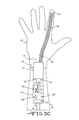
- FIG. 3C shows an alternate embodiment of the electrical connection between the electrifiable surgical glove and the gown with an electronic I/O module that gives direct feedbacks to the surgeon.
- FIG. 4 is a top view of an alternate embodiment of the electrical connection between the surgical glove and the neuromonitoring computer system.
- FIG. 4A is an isometric view of an assembly of the electrode patch and the electrode connector.
- FIG. 4B is a top view of an assembly of the electrode patch and the electrode connector.
- FIG. 5 is a top view of a bipolar electrical connection between the surgical glove and the neuromonitoring system.
- FIG. 5A is a cross section view of the bipolar electrical connector.
- FIG. 6 is a right side view of a hand with the electrifiable surgical glove of the preferred embodiment demonstrating electrical connectivity to a surgical instrument.
- FIG. 6A is a bottom view of a hand with the electrifiable surgical glove of the preferred embodiment demonstrating electrical connectivity to a surgical instrument.
- FIG. 6B is a bottom view of an alternate embodiment of the surgical glove of the present invention.
- FIG. 7 is a top view of a hand with the electrifiable surgical glove of an alternate embodiment demonstrating the detection of the electrical connectivity to a surgical instrument.
- FIG. 7A is a top view of a hand with the electrifiable surgical glove of an alternate embodiment showing the electrical path for detection of the electrical connectivity to a surgical instrument.
- FIG. 8 is a bottom view of another alternate embodiment of the surgical glove of the present invention.
- FIG. 9 is a right side view of another alternate embodiment of the surgical glove of the present invention.
- FIG. 10 is a side view showing the use of the novel surgical glove during a surgical procedure.
- FIG. 10A is a closer view of an alternate embodiment of the surgical glove.
- FIG. 10B is a bottom view of a hand with the electrifiable surgical glove of an alternate embodiment.
- FIG. 10C is a top view of a hand with the electrifiable surgical glove of an alternate embodiment.
- FIG. 11 is an isometric view showing the use of the novel surgical glove during a surgical procedure.
- FIG. 12 is a side view of the electrifiable surgical glove holding an electrifiable wireless retractor to protect a nerve near the vertebrae.
- FIG. 13 is an isometric view of an electrifiable wireless rongeur.
- FIG. 14 is an isometric view of an electrifiable wireless awl.
- FIG. 15 is an isometric view of an electrifiable wireless surgical probe.
- FIG. 16 is an isometric view of an electrifiable wireless bipolar surgical probe.
- FIG. 17 is an isometric view of an electrifiable wireless screw driver handle.
- FIG. 18 is an isometric view of an assembly of electrifiable wireless cannulae retractors.
- FIG. 19 is an isometric view of an electrifiable wireless distractor.
- FIG. 20 is an isometric view of an electrifiable wireless implant trial instrument.
- FIG. 21 is an isometric view of an electrifiable wireless curette.
- FIG. 22 is an isometric view of an electrifiable wireless annulotomy knife.
- FIG. 23 shows a graph of the elongation vs. electrical resistance of the novel electrically conductive compound sprayed on a neoprene film.
- FIG. 24 shows a different graph of the elongation vs. electrical resistance of the novel electrically conductive compound sprayed on a neoprene film.
- FIG. 25 shows a graph of the elongation vs. electrical resistance of the novel electrically conductive compound sprayed on a neoprene film during a cyclic test.
- FIG. 26 shows a graph of the elongation vs. electrical resistance of the novel electrically conductive compound dispensed on a neoprene film.
- FIG. 27 shows a different graph of the elongation vs. electrical resistance of the novel electrically conductive compound dispensed on a neoprene film.
- FIG. 29 shows a picture of the sprayed and dispensed electrically conductive compound on a neoprene film.
- FIG. 30 shows a close-up picture of the sprayed and dispensed electrically conductive compound on a neoprene film.
- FIG. 31 shows the evolution of the electrical resistance of a novel stretchable wire made with a silicone tube having the electrically conductive compound in it during cyclic elongations.
- FIG. 32 shows the evolution of the electrical resistance of a stretchable wire made with a silicone tube having the electrically conductive compound in it during cyclic elongations.
- FIG. 33 shows a graph of the elongation vs. electrical resistance of a stretchable wire made with a silicone tube having the electrically conductive compound in it.
- FIG. 34 shows a graph of the elongation vs. electrical resistance of a stretchable wire made with a neoprene film having the electrically conductive compound on it.
- FIG. 35 shows the bottom half of a stretchable wire.
- FIG. 36 shows the upper half of a stretchable wire.
- FIG. 37 shows a cross section of the bottom half of a stretchable wire.
- FIG. 38 shows a cross section of the upper half of a stretchable wire.
- FIG. 39 shows the assembly of the two halves of a stretchable wire.
- FIG. 40 shows the bottom and upper halves of a different stretchable wire.
- FIG. 41 shows the assembly of the two halves of a different stretchable wire.
- FIG. 42 shows a typical in-line manufacturing process of a stretchable wire.
- FIG. 1 the surgeon 13 is illustrated next, and hopefully performing, to a patient 8 , positioned on a surgical table 9 , undergoing a lower lumbar spine surgery.
- Neuromonitoring and stimulation devices are installed on the patient to provide information to the IONM specialist through the neuromonitoring computer system 1 .
- EMG electrodes 11 are placed on the lower limbs to monitor free-run EMG.
- Stimulating SSEP electrodes 67 are placed on the lower limbs to send an electric signal that will be used to measure the SSEP modality with the SSEP electrode 71 placed on the head of the patient.
- Stimulating TcMEP electrodes 72 are placed on the head of the patient and sent an electrical input that is measured with the TcMEP electrodes 68 placed on the lower limbs of the patient. Train-of-four input electrodes 73 are placed on the arm of the patient and used to measure the affects of the muscle relaxant. Although not all shown, anode electrodes or reference electrodes are present in order to complete the electrical circuits. Neuromonitoring modalities can be adapted, added or relocated depending on the type of surgery. Stimulating electrodes can be needle electrodes inserted into the skin or surface electrodes or alternately stimulation may be done by a wireless instrument 17 . Sensing electrodes can be needle electrodes, surface electrodes or any other kind of mechanical, electrical or optical sensors such as accelerometers, gyros, strain gages, pressure sensors, fiber optics or acoustic sensors.
- connection wires 10 In a lower lumbar spine surgery, lower limb are monitored and neuromonitoring modalities are wired to the main connection box 6 through connection wires 10 . Alternately multiple connection boxes may be used for instance one for the left side of the patient and another for the right side of the patient. Head neuromonitoring modalities are wired to the remote connection box 69 trough connection wires 74 .
- the remote connection box 69 is wired to the main connection box 6 trough wire 70 or alternately wirelessly connected directly to the computer system 1 . In another configuration, the remote connection box 69 may not be used and all the neuromonitoring wires 10 , 74 would be connected to a single connection box 6 .
- the main connection box 6 has a wireless connection 66 to the neuromonitoring computer system 1 through a wireless transmitter 3 .
- the neuromonitoring computer system 1 has wireless connections to the main connection box 6 and the remote screen 4 through a wireless transmitter 64 .
- Connection box 69 and connection box 6 are adapted to be placed under the surgical site preparation to avoid issues of sterilization, however it is contemplated that these boxes would be located within the surgical field. In a traditional set-up these junction boxes 6 , 69 would be hardwired to the computer system 1 . However it is desirable to eliminate wiring from the connection boxes to the computer eliminating electrical cords crossing the sterile field eliminating sources of unwanted noise and simplifying the concerns of signal contamination from electrosurgical devices. Alternately the invention should not be limited to wireless connectivity as wireless connection 65 and wireless connection 66 could both be hardwired should the IONM tech desire.
- the remote screen 4 has a wireless connection 65 to the neuromonitoring computer system 1 through a wireless transmitter 2 .
- the remote screen 4 is a display screen that can be positioned anywhere in the operating room, generally in a line of sight of the surgeon or for visualization by other members of the medical team or by the sales representative who are frequently assisting with surgical protocol information.
- the information displayed on this screen is either a supplementary feedback generated by the IONM specialist or real time information automatically generated by a computer algorithm computerized at the neuromonitoring computer system 1 such as nerve avoidance algorithms with color coded signals allowing the surgeon to see or hear his approach towards a nerve.
- the remote screen may also communicate such information as necessary for the surgeon to understand when he is in electrical contact with the surgical instrument 17 , when he is sending stimulating current into the body and different useful information on status and modes of the neuromonitoring system.
- the surgeon 13 wears an electrifiable surgical glove 14 that includes at least one electrical conductive open contact surface 15 to hold the instrument 17 .
- the electrifiable surgical glove 14 is electrically connected to the gown 20 through an electrical sleeve connection 16 .
- the electrical sleeve connection 16 is electrically connected to the gown electrical path 51 which then connects to the electrical gown connection 21 .
- the main electrical path 5 connects to the gown 20 through the electric gown connection 21 to the main connection box 6 which contains pre-amplifiers for sensing electrodes and stimulators for generating electrical stimulation currents.
- a common electrode is usually placed on the patient's skin to provide a ground reference to the pre-amplifiers of the main connection box 6 .
- the main electrical path 5 has at least one conductor to send an electrical stimulation current to the electrifiable surgical glove 14 .
- reference wire 7 is connected to main connection box 6 and is placed on or into the patient's skin through the reference electrode 12 .
- This reference electrode is also called anode electrode, the cathode being the instrument 17 that sends the stimulations.
- the reference electrode 12 is usually placed in the near proximity of the surgical site, in the opposite side of the opening. Therefore, most of the nerves to monitor are located in between the reference electrode and the source of electrical stimulation in such a way that the current flows through a short portion of the patient's body.
- the reference electrode is placed far away from the ground electrode of the electrosurgical device in order to attenuate potential artifacts.
- the electrical stimulation current flows through the electrified glove 14 via the electrically conductive wireless surgical instrument 17 into the patient's body, to the reference electrode 12 .
- FIG. 1A An alternative glove connection to FIG. 1 is shown in FIG. 1A where the surgeon may wear two electrifiable gloves 14 that are electrically connected via the gown electrical path 51 ′, which goes from one side of the surgeon's electrical sleeve connection 16 to the other side.
- a stimulator 112 having a reference electrode placed on or into the patient's skin and a wireless transmission 115 to the neuromonitoring computer system 1 is located on the patient as shown or alternately carried by the surgeon not shown.
- the stimulator has a wireless transmitter 114 in communication with the neuromonitoring computer system transmitter 64 .
- the surgeon 13 closes the electrical circuit by holding the handle 113 of the remote wire 111 with one hand and the instrument 17 in the other hand.
- the wireless stimulator 112 has a small battery that provides energy to the electronics to generate the electrical stimulations during the surgery and insure wireless communication with the computer system 1 . Further, the wireless stimulator unit may be a single-use sterile device.
- the surgeon 13 uses a wireless electrifiable surgical instrument 17 that has an electrically conductive handle 18 . It is desirable to have a tactile feeling in the handle 18 while making it comfortable for the surgeon 13 to use and may be molded from an electrically conductive silicone or soft electrically conductive material such polyurethane or TPE. Alternatively it could also be made from metal, however to reduce the weight of the instrument it may be preferred to hollow out the metal handle 18 .
- the handle 18 must then be in electrical contact with the instrument's end effector 19 so that an electrical current may be sent through it.
- An electrically insulating over-coating usually covers most of the body of the instrument.
- the end effector 19 is the only electrical conductive open surface of the distal portion of the instrument and has only a few square millimeters. In different embodiments, the instrument may have multiple end effectors.
- the small size of the open conductive surface is very important for getting accurate results on nerve location and nerve health assessment. To large of a surface would spread the stimulation current into wider areas of tissue and body fluids and stimulation current threshold needed for depolarizing a nerve from a certain distance would be affected and therefore wrong indication of safety would be given to the IONM specialist and surgeon. It is important that the currents being sent through these surgical gloves 14 and instrumentation 17 be relatively low, for instance below 200 milliamps of current, in comparison to electrosurgical devices like electrocautery or powered tools which operate at inherently higher more dangerous current levels.
- surgeon 13 will be free to palpate the patient 8 with the glove 14 directly without exposing the patient or the surgical team any risk of being shocked. In this way the surgeon 13 is free to focus on the surgical procedure and to be continually stimulating the surgical site through various tools 17 and end effectors 19 or the glove 14 in order that the IONM or the surgeon may monitor the activity of the nerves to avoid injury and ensure patient safety during the procedure.
- the gown electrical path 51 is isolated along the gown 20 and in a preferred embodiment delivered along with electrical connections 16 and 21 as part of the gown in a single-use sterile condition to the hospital.
- the gown electrical path 51 and the electrical connections 16 and 21 may be delivered as an independent sterile item which is subsequently attached to an existing sterile gown 20 by some known attachment method such as a tape or an adhesive.
- the electrical gown connection 21 can use any electrical connector but preferably a connector that holds well but can be disconnected with a small tug as the surgeon 13 moves away from the surgical table 9 .
- the connection 16 should also easily be connected to the glove 14 while the surgeon 13 is gowning and should also be easily removable should the surgeon decide to change gloves during the procedure.
- the electrical sleeve connection 16 connects the electrifiable surgical glove 14 to the gown 20 .
- Those two glove electrical conductive open contact surfaces 22 , 23 are electrically connected to the gown through electrically conductive adhesive tapes 35 , 76 that connect to the electrical connection patches 24 , 25 mounted on the gown.
- Connection patches 24 , 25 connect to conductors 52 , 53 that compose the gown electrical path 51 .
- Electrically conductive adhesive tapes 35 , 76 are part of the glove and mounted on an isolated strip 34 .
- the pull-protecting tab 33 covers the adhesive portion of the electrically conductive adhesive tapes 35 , 76 as shown in FIG. 3B which is an alternate cross section for FIG. 3A .
- the pull-protecting tab 33 is pulled ( 75 ) to unprotect the adhesive portion of the electrically conductive adhesive tapes 35 , 76 and the electrical connection is made to electrical connection patches 24 , 25 .
- the pull-protecting tab 33 is pulled away ( 56 ), which breaks the adhesion between the conductive adhesive tapes 35 , 76 and the electrical connection patches 24 , 25 .
- the adhesive tapes 35 , 76 could carry wires not shown which would replace the electrical conductivity of the tape. In this case the adhesive would simply act to hold the wires in electrical contact with the glove.
- the location of the electrical connection on the glove is important and placed in such a way that disturbance is minimized. It has been shown that the area of the top of the hand, between the wrist and the first joints of the fingers, is a good location but sometime in the way when the surgeon needs to insert his/her hand deep inside the wound.
- the electrical connection is made on the top of the hand, in the middle of the glove cuff, below the wrist joint. This portion of the glove is usually pulled over the gown cuff and would not affect the tactile feeling or reduce the freedom of movements of the surgeon. A little space between the electrical connection and the far end of the glove cuff is avoided, usually over 25 mm, in order to facilitate handling of the glove during donning. This portion of the glove is also the most stretched part and placing the electrical connection there would increase the risk of damaging them when putting the glove on the hand.
- the sleeve connection 16 is not limited to the described preferred embodiment and could be made of any other mechanical/electrical connection, including electrical conductive hook and loop tape (Velcro®). The sleeve connection 16 could also be placed all around the glove cuff.
- the electronic module 127 gives feedbacks to the surgeon on the status of the nervous system.
- the module includes lights 130 to indicate the proximity of the instrument to a nervous system component and could also, indicates if the electrifiable glove holds a surgical instrument.
- the module also includes a switch 131 that can turn on or off the electrical stimulation that is transmitted to the electrifiable glove.
- the digital screen 129 displays lettered or numbered feedback to the surgeons and the scroll wheel, trackball or joystick 128 is used to control and navigate through the menus and information displayed on the remote screen 4 shown on FIG. 1 .
- the electronic module 127 can be placed on the electrifiable 14 glove, the gown 20 or the isolated strip 34 between the glove and the gown.
- the electronic module may also emit different sounds or vibrations to give feedbacks to the surgeon on the status of the nervous system.
- the electronic module that emits sounds may be placed in the collar of the surgical gown, closer to the surgeon's ears.
- the gown electrical path 51 may include additional electrical conductors that form a data bus, as example similar to the Universal Serial Bus (USB). In reference to the preferred embodiment described above, this data bus is connected and exchanges data with the neuromonitoring computer system 1 through the connection box 6 .
- USB Universal Serial Bus
- Electrode patches 140 are fixed to the surgical glove, creating an electrical contact to the glove electrical conductive open contact surfaces 22 , 23 .
- the electrode patches 140 are made with an electrode male stud 141 that clips into the electrode clip 142 of the electrode connectors 145 .
- the electrical connection is made on the top of the hand, in the middle of the glove cuff, below the wrist joint in order to not affect the tactile feeling or reduce the freedom of movements of the surgeon and avoid excessive stretching of the electrode patches during donning.
- FIG. 4A an assembly of the electrical sleeve connection 16 that comprises at least one electrode patch 140 and the mating electrode connector 145 is shown.
- the electrode male stud 141 clips into the electrode clip 142 .
- the electrode connector 145 has a wire 146 that is connected to the neuromonitoring computer system 1 and transmits the stimulation current to the electrode clip 142 .
- a light 143 and a switch 144 are mounted on the electrode connector 145 .
- the light 143 informs the surgeon on the proximity of a surgical instrument to a nervous structure.
- the switch 144 allows the surgeon to turn on and off the stimulation current and also, to switch from the right side to the left side surgical glove and select which electrical path is stimulating.
- FIG. 4B shows a top view of FIG. 4A .
- a bipolar electrode patch 140 is used to make the electrical connection between the surgical glove 14 and the neuromonitoring computer system 1 .
- only one electrode patch 140 is fixed to the surgical glove, creating both electrical contacts to the glove electrical conductive open contact surfaces 22 and 23 .
- FIG. 5A shows a cross section of the electrode patch 140 .
- the central portion of the male electrode stud 146 ensures the electrical connection with the conductive path 23 .
- the outside portion 148 of the stud ensures the electrical connection with the conductive path 22 .
- An isolative portion 147 in between the two poles ensures electrically independence of the electrical paths.
- An O-ring (not shown in the figure) may be used to seal the electrical connections between the stud and the connector from liquid or blood entering inside the connection and potentially short-cutting the electrical signals.
- the adhesive portion 149 of the electrode patch 140 is firmly attaching the bipolar electrode patch on the surgical glove 14 .
- a bipolar electrode connector is clipped onto the male electrode stud to ensure electrical connections to the neuromonitoring computer system 1 .
- the electrical connection is made on the top of the hand, in the middle of the glove cuff, below the wrist joint in order to not affect the tactile feeling or reduce the freedom of movements of the surgeon and avoid excessive stretching of the connection during donning.
- the electrifiable surgical glove 14 has at least one glove electrical conductive open contact surface 22 on its outside surface.
- the at least one glove stimulating conductive open contact surface 22 is used to transmit the stimulation current in the wireless instrument 26 .
- the stimulation electrical current flows through the electrified glove via an electrically conductive wireless surgical instrument 26 into the patient's body to the reference electrode 12 also shown in FIG. 1 .
- an insulating coating 134 may partially cover the open conductive surface. In this way, the electrical open conductive surfaces 22 ′ are mainly located where the wireless surgical instrument is touching the glove and chance to inadvertently send stimulation current into the patient's body is limited.
- the open conductive surfaces 22 ′ are located on the palm side of the glove, on the internal face of the index and on the internal face of the thumb. All the other areas are over-coated with an isolative layer. It is understood that the disposition and shape of the glove electrical conductive open contact surface 22 is not limited to what is shown. FIG. 6B shows another pattern of the glove electrical conductive open contact surface 22 without any isolative over-coating. It is also understood that the electrifiable surgical glove can have more than one stimulating electrical conductive open contact surface 22 in order to make electrical contact with multiple electrical portions of a wireless instrument.
- the electrifiable surgical glove 14 shown in FIGS. 7 and 7A has a presence conductive open contact surface 158 that is used as an electrical switch that detects the presence of an electrically conductive wireless surgical instrument.
- the glove presence conductive open contact surface 158 is positioned in a way where it should not have contact with the patient while the instrument is in the surgeon's hand.
- the electrical circuit is closed between the two glove electrical conductive open contact surfaces 22 , 158 . So, when the electrical circuit is closed, an electrically conductive surgical instrument is in the hand of the surgeon. This is supplementary information to the IONM specialist who knows when an instrument is connected to the glove and ready to stimulate.
- the closing of the electrical circuit, between the glove stimulating conductive open contact surface 22 , the electrically conductive wireless instrument, the patient's body and the reference electrode 12 is detected by either the neuromonitoring computer system 1 or the main connection box 6 , and the IONM specialist is informed that the instrument is connected to the glove and stimulating into the patient's body.
- the automatic communication of this information to IONM specialist allows them to know if the stimulator is on and working without having to interrupt the surgeon's concentration. It also allows them to be prepared when to monitor nerve location since the instrument is likely in use while in the surgeon's hands.
- the feedback on connectivity to the instrument and the instrument stimulation can also be displayed on the remote screen 4 should the surgeon want to check the connection without having to communicate with the IONM specialist. It is understood that the disposition and shape of the two glove electrical conductive open contact surfaces 22 and 158 are not limited to what is shown. It is also understood that the electrifiable surgical glove can have more than one stimulating electrical conductive open contact surface 22 .
- the electrifiable surgical glove 14 has a full glove electrical conductive open contact surface 28 .
- This full glove electrical conductive open contact surface 28 is used to transmit the stimulation current in the wireless instrument.
- the stimulation electrical current flows through the electrified glove via an electrically conductive wireless surgical instrument into the patient's body to the reference electrode 12 .
- the closing of the electrical circuit, between the glove electrical conductive open contact surface 28 , the electrically conductive wireless instrument, the patient's body and the reference electrode 12 is detected by either the neuromonitoring computer system 1 or the main connection box 6 , and the IONM specialist is informed that the instrument is connected to the glove and stimulating into the patient's body.
- the feedback of the instrument stimulating can also be displayed on the remote screen 4 .
- the electrical conductive path may be mounted on a standard surgical glove that has been taken off its sterile packaging in the operating room and worn by the surgeon.
- the electrical conductive pad is supplied in a sterile condition and ready to be affixed on the surgical glove.
- the electrical conductive path shown in FIG. 9 has an electrically conductive ring 135 which can be placed around a finger. It has been shown that a small ring around the finger would not disturb too much the freedom of movements of the surgeon's finger and not affect his/her tactile feeling. Moreover, the ring would be in most cases in contact with different kind of instruments that the surgeon may hold.
- the electrical conductor 139 has an elongated portion with two ends, one end 138 starts at the cuff side of the glove 14 and the second end 137 is connected to ring.
- An insulated portion 136 may be disposed between the two ends and may be used to affix the electrical conductor on the surface of the glove.
- the insulated portion 136 can be an adhesive tape that is stuck on the glove or any other kind of elements that will help the fixation of the electrical conductor 139 on the surface of the glove.
- This insulated conductor runs on the top or on the side of the finger and on the top of the hand to minimize the effect on the tactile feeling of the surgeon.
- the cuff end 138 is connected to the electrical sleeve connection 16 as described in the other embodiments.
- This electrically conductive ring 135 connected to the electrical conductor 139 and disposed around the finger, on the surface of the glove is used to transmit the stimulation current in the wireless instrument.
- the stimulation electrical current flows through an electrically conductive wireless surgical instrument into the patient's body to the reference electrode 12 .
- the closing of the electrical circuit, between the electrical conductor 139 , the electrically conductive ring 135 , the electrically conductive wireless instrument, the patient's body and the reference electrode 12 is detected by either the neuromonitoring computer system 1 or the main connection box 6 , and the IONM specialist is informed that the instrument is connected to the glove and stimulating into the patient's body.
- the feedback of the instrument stimulating can also be displayed on the remote screen 4 .
- the electrically conductive ring shown on this figure can be made of any other kind of electrically conductive open surface that is mounted somewhere on the surface of the glove in a location that would minimize the impact on the surgeon's tactile feeling.
- the electrical conductive path can be made of any electrically conductive material which can be a silicone based adhesive, a conductive polymer, a conductive fabric, or any other electrically conductive adhesive.
- the electrical conductive path may be a conductive glove as describe in FIG. 6 with the fingers cut off as example. This partial glove can be worn over the standard surgical glove.
- the cuff end is connected to the electrical sleeve connection as described in the other embodiments.
- the partial glove doesn't act as the primarily protective barrier, its thickness can be reduced to a minimum to not affect the tactile feeling.
- at least one finger cot having an electrically conductive open surface could be worn over the standard surgical glove.
- An electrical conductor having an insulated portion is used to connect the finger cot to the cuff end, as described previously. Since the finger cot doesn't act as the primarily protective barrier and limited mechanical strength is required, its thickness can be reduced to a minimum, in instance below 5 mils, and tactile feeling would not be affected too much.
- the electrifiable surgical glove 14 is used to determine the relative proximity and location of a nervous system component 36 by palpating the soft tissues 37 surrounding the vertebrae 30 .
- the glove is inserted through an incision 39 on the skin 38 of the patient.
- the electrical stimulation current is sent from the stimulating electrical conductive open contact surface 133 , usually located on the tip of the finger into the patient's body.
- the stimulation current flows through the tissues to the reference electrode placed in the near proximity of the surgical site.
- the amplitude of the current sent is set sufficiently high in order to reach and depolarize the nerves running into the stimulated tissues and potentials will be evoked in the related muscles.
- EMG signals will be recorded on the neuromonitoring system via electrodes placed on or in the patient's muscles.
- any variation of the neuromonitoring modalities informs the IONM specialist and the surgeon on the relative proximity of the nervous system component 36 .
- the variations of modalities are treated by a computer algorithm in relation with the stimulation current and direct information on relative proximity and location is displayed on the remote screen 4 .
- Pre-defined threshold values can be set in the system and color lights are displayed on the remote screen or sounds can signal to indicate the relative proximity between the glove stimulating electrical conductive open contact surface 133 and the nervous system component.
- FIG. 10A shows a different embodiment of the electrifiable surgical glove 14 that is used to perform the palpating of the soft tissues.
- the electrifiable surgical glove has two electrical paths.
- the first path is the electrical conductive open contact surface 23 that is over-coated with an isolated electrical path 132 to only leave a small spot electrically open 133 .
- the stimulation patch 133 is used to concentrate the electrical stimulation to a small area in order to focus this stimulation be able to determine the proximity of this patch to a nervous system component.
- the second path is the conductive open surface contact 22 described above that is used to connect the electrical stimulation to a surgical instrument. In a still different embodiment, those two paths can be used to perform a bipolar stimulation.
- FIGS. 10B and 10C show the glove electrical conductive open contact surfaces 22 going from the palm side of the hand towards the back of the hand passing along both side of the hand and joining back together on the glove's cuff. This ensures electrical redundancy if one of the two paths along the side of the hand becomes not conductive due to abnormal wear.
- protective electrical insulating over-coating 134 covers areas of the glove that will not be in contact with instruments.
- This protective electrical insulating over-coating may be transparent, but still in a preferred embodiment, color pigments of the same color as the glove material are used in order to hide the electrical non-conductive surfaces. This color differentiation between the conductive surface and the insulated surface gives intuitive indication to the surgeon where and how to hold instruments in order to insure electrical connection.
- Glove electrical conductive open contact surface 23 can also run over the top surface of the index or be on the side of the index.
- a protective electrically insulating over-coating 132 covers most of the conductive path to only leave an electrical conductive open surface 133 of a few square millimeters at the tip of the finger. The small size of the open conductive spot is very important for getting accurate results on nerve location and nerve health assessment.
- both electrical conductive open contact surfaces end on the top side of the hand in a location that does not bother or limit the surgeon's wrist movements. Electrical sleeve connections not shown on these figures are fixed on the ends of the electrical conductive open contact surfaces as described in the FIGS. 3, 4 and 5 . It is understood that the electrical conductive open surface pattern and placement, the protective insulating over-coating pattern and placement could vary from what is shown on the figures and the electrical sleeve connection could be positioned anywhere around the glove's cuff.
- the physical aspect of the glove electrical conductive open contact surfaces 22 , 23 , 28 , 133 and the electrical insulating over-coating 132 and 134 is a novelty of this invention.
- the tactile feeling of the novel electrifiable surgical glove does not modify the actual surgical gloves tactile feeling.
- a natural rubber surgical glove is usually made by dipping a ceramic former into a coagulant bath. This coagulant bath is generally obtained by mixing water with calcium nitrate, calcium carbonate and some dispersants and thickeners.
- the calcium nitrate is used to initiate the coagulation process of the latex and the calcium carbonate is acting as a mold release.
- the former is dipped into the latex compound, which is the base material of the glove.
- This compound is usually a water-based rubber like natural rubber.
- Other glove materials like nitrile, polyisoprene, polychloroprene (also known under DuPont's trade name Neoprene) or vinyl are manufactured with similar concepts.
- the dipping process may be repeated several times in order to build up the appropriate thickness.
- the layer being on the ceramic former is called gel latex.
- multiple dipping in different baths are made for leaching, cleaning and eventually coating the glove.
- a final curing process at an elevated temperature occurs in order to give to the rubber its final mechanical properties.
- the thickness of a surgical glove is usually between 8 and 15 mils (thousandth of an inch) depending on the material used and the level of robustness is wanted. This range of thickness along with the elasticity of the material is important in order to give a maximal tactile sensitivity to the surgeon without compromising the efficiency of the protective barrier and the mechanical properties of the glove. Thicker gloves similar to those used in commercial applications would highly reduce the tactile feeling and therefore compromise the dexterity of the surgeon.
- One of the key aspects of the present invention is to not affect the tactile sensitivity of the glove when creating the electrical conductive pathways. Most surgeons wear two pairs of gloves to increase the protection barrier and reduce the risk of contamination if the outer glove is cut.
- any addition to the surgical glove material needs to be stretchable and have similar mechanical properties like strength, elongation and resilience.
- conductive materials can be used to conduct electricity. Any conductive biocompatible material can be used, like metals, polymers, carbon particles or carbon nanotubes.
- integrating the conductive layer during the glove manufacturing process can be made of two different ways: creating a glove material that is intrinsically conductive or adding a conductive layer within the glove.
- conductive filler has to be integrated into the glove material compound.
- the conductivity of the glove needs to be below 2000 Ohms, so the quantity of conductive filler needs to be relatively important.
- the challenge is that by adding a certain quantity of filler, the glove material loses its mechanical properties. Therefore, only a few fillers can fulfill this function.
- Fillers like polyaniline (PANI) are polymers that are intrinsically conductive and by nature, have some elastic properties that can be similar to a surgical glove.
- the right conductive filler can be added to the glove material compound and the ceramic former is then dipped into the compound to create the fully conductive glove. Then, the glove material without filler can be put over the first layer by ways of airbrushing, spraying, dispensing or partial over-dipping in order to insulate the appropriate locations of the glove.
- Another option is to incorporate the conductive layer as an initial step of the manufacturing process of the surgical glove. Conductive coating can be pre-deposited on the hand former used to manufacture surgical glove prior to over dip it into the glove material. A short drying period may be observed between the dips in order to not contaminate the second compound. By doing so, the conductive coating bonds to the glove material during the final curing process and creates a strong adherence.
- the conductive layer can be added on the glove material, after the initial dipping in the base non-conductive material, when it's still in a gel state. After a short period of drying but still during the gel phase, the conductive layer is added to the gel glove.
- This conductive layer is a compound made of a polymer, a conductive filler, and other additives like dispersant, rheology modifier, surfactant, defoamers and the like.
- the conductive layer can be added in many ways like over-dipping, spraying, airbrushing, dispensing.
- the isolative layer is added over the appropriate areas. This isolative layer can also be sprayed, dispensed, airbrushed, partially over-dipped or other means of adding material on selective areas.
- the conductive material is put on the surgical glove after it has been cured.
- the prior art mentions the potential to coat gloves using vapor deposition processes. We have found that the electrical connection done using these processes only work in an un-stretched state. Once a glove is coated with a physical vapor deposition (PVD) process, the coated particles form miniature islands when stretched and continuous electrical contact is not possible. Therefore when using vapor deposition, we suggest the following process: forming a surgical glove from a base material, expand the surgical glove to a maximum usable size, hold the glove in the expanded state, coat the glove with a second conductive material using vapor deposition process or any other coating process, allow the glove to cure if necessary which depends on the material used to coat, release the glove, sterilize and package.
- PVD physical vapor deposition
- both conductive material and isolative layers are coated on the finished surgical glove, after it has been cured.
- These coatings need to be well bonded and integrated on the surface of the base rubber glove in order to resist to abrasion and contact to fluids and blood that occurs during surgeries. It has been experimented that most of the materials having a good primarily bonding on rubber gloves have tendency to easily delaminate after a stretch of the base rubber. This is mostly due to a difference in the mechanical properties such as elongation, modulus of elasticity and resilience of the rubber and the coatings. In instance, when stretching the base rubber, if the coating deforms differently, a shear stress occurs between the two materials and breaks the bond between the two layers.
- the coatings used electrically conductive or not, have the ability of following the deformations of the base rubber glove without affecting it.
- the ultimate elongation required by the standards for synthetic rubber surgical gloves is 650% before aging. It has been experimented that a surgical glove during the donning process can be stretched up to 300%. In order to fit tightly on the surgeon's hands and insure a good tactile feeling, it has also been experimented that a glove could be stretched up to 50% when worn. Talking more particularly about the electrically conductive layer, these two values mean that the electrically conductive coating needs to still be conductive after a stretch of 300% and has to still be electrically conductive when stretched 50%.
- the conductive coating is made out of a carrier, which is a resin in the families of acrylic, styrene, urethane, silicone, vinyl, chloroprene or the like, a conductive filler such as metals, carbon black, intrinsically conductive polymer, carbon nanotubes and different additives like a dispersant helping the dispersion of the conductive particles into the resin, rheology modifier, surfactants, etc.
- a carrier which is a resin in the families of acrylic, styrene, urethane, silicone, vinyl, chloroprene or the like
- a conductive filler such as metals, carbon black, intrinsically conductive polymer, carbon nanotubes and different additives like a dispersant helping the dispersion of the conductive particles into the resin, rheology modifier, surfactants, etc.
- the flat, rough and irregular geometry of the silver flakes allows them to interlace with each other and forms long and more robust electrically conductive chains, even when stretched. This particular geometry also gives them good grip when mixed and dried into elastomeric materials.
- the average size of the flakes plays an important role in the electrical conductivity and optimal results were obtained with average flakes size between 5 and 15 microns.
- the lowest concentration of filler is wanted. This can be achieved by measuring the electrical resistivity of the material at different concentration of filler and reporting the data on a graph. The resulting graph is called the percolation curve.
- Another series of experiments have been made by measuring the tensile strength of the conductive coating at different concentration of filler and reporting the data on a graph.
- the resilience of the different materials may affect the recovery of the conductive coating. If the conductive coating is forced to recover too quickly, the disposition of the flakes changes and the electrical conductivity may be lost. If plastic deformation in one of the materials surrounding the conductive layer or a plastic deformation of the resin occurs, electrical conductivity may be lost too.
- Optimum electrically conductive properties during stretching are obtained when the molecules of the resin holding a silver flake are elastic enough to follow the deformation of the substrate without breaking apart while staying bonded to it. Resins in the styrene family have given the best results and met the requirements previously described.
- the third important element for obtaining good electrically conductive coatings is the dispersion of the conductive filler into the resin.
- the surface tension in the resin forces the flakes to stay on the surface.
- a dispersant agent comprising surfactants is necessary in order to modify the surface tension and improve the dispersion, the separation and the wetting rate of the silver particles when mixed into the resins. Viscosity and pH of the solution need to be precisely controlled in order to obtained good and constant electrical properties.
- a good and homogenous dispersion of the conductive filler into the resin improves the electrical conductivity of the compound for a given concentration of filler.
- the use of a dispersant agent is necessary in the compounding of a stretchable electrically conductive coating. Since metallic fillers have a volumetric mass higher than the resins, the metallic particles once dispersed have tendency to settle down. Active stirring of the compound is important before and during the coating process. Quick drying of the coating also avoids the conductive particles to settle down once applied on the base rubber glove.
- the thickness of the conductive coating plays also a key role in the electrical and mechanical performances of the layer. A thick layer gives a more robust and more conductive coating. Moreover, a thin layer is desirable in order to not affect the tactile feeling of the surgeon.
- Conductive layers having a thickness between 1 and 3 mils (thousandth of an inch) have given the best compromise between mechanical and electrical properties and met the requirements previously described. It has been demonstrated that even with good bonding properties, the electrically conductive coating might present a risk of delaminating off the base glove or wearing out too quickly under aggressive abrasions. It is well known that surgical gloves are exposed to aggressive abrasion when the surgeon uses certain instruments or touches sharp bones. Therefore, a protective coating being thin enough to conduct the electricity through it but strong enough and adhering well to the base glove material has been developed and over-coated on the conductive coating. As discussed before, this protective coating must have similar mechanical properties than the glove material and the conductive coating.
- Polymers in the urethane family have given the best results but may be selected in the families of acrylic, styrene, silicone, vinyl, chloroprene or the like.
- the protective coating has a thickness under 1 mil in order to not affect the tactile feeling of the surgeon and still be electrically conductive through it.
- an electrically non-conductive coating is needed to partially cover and insolate the electrically open conductive path made on the glove.
- Color pigments may be mixed in the isolative coating in order to differentiate electrically conductive and electrically non-conductive areas of the glove. Best results have been obtained by using the same polymer than the protective coating with a higher concentration of solids and by making a layer thickness between 1 and 3 mils.
- the protective layer can be applied on the conductive coating only in the areas that are not insulated. Depending on the manufacturing process used, it could be easier to apply the protective coating over the complete electrically conductive layer and then partially insulate the appropriate areas over the first two layers.
- the electrically conductive layer could be made using both water-based and solvent-based resins and similar electrical and mechanical performances are obtained. Moreover, it has been demonstrated that the best adherence results with the base glove material were obtained with the solvent-based resins.
- the electrically conductive coating and the protective and insolating coatings can be applied on the glove by different manufacturing processes like spraying or airbrushing, paint brushing, sponge brushing, dispensing, etc. Continuous stirring of the conductive coating is important to keep the filler particles dispersed in solution. Drying the coating after each layer is also important to obtain good bonding properties.
- the conductive coating, the protective coating and finally the isolative coating are applied on a cured surgical glove.
- the glove is stretched during the application of at least one coating. This improves the electrical conductivity properties when the glove is stretched beyond the limits previously discussed.
- the electrifiable surgical glove 14 holds an electrically conductive wireless screwdriver 32 to thread a pedicle screw 29 into the pedicle canal 31 of a vertebra 30 .
- a stimulation current flows from the glove electrical conductive open contact surface 22 , through the screwdriver electrical contact 63 , to the isolated portion of the screwdriver 62 , to the end effector 61 , to the pedicle screw 29 , to the vertebrae 30 and finally to the reference electrode 12 .
- the readings from the neuromonitoring modalities can determine in a real time manner when screwing the screw if there is a breach in the pedicle canal of the vertebrae.
- the screwdriver handle can be a modular fixed or ratcheting handle where a screwdriver shaft is affixed into it by a quick coupling mechanism.
- the proximal portion of the screwdriver shaft and the distal portion of the wireless modular handle quick coupling both have electrically open conductive surfaces that are in contact when the shaft is coupled with the modular handle.
- Other instruments like drill bits, taps, scrappers, all having an electrically conductive end effector, an insulated core and a proximal electrically open conductive surface, may be connected to the modular quick coupling handle and electrically stimulated when the surgical glove holds the handle.
- the electrifiable surgical glove 14 holds an electrically conductive wireless surgical retractor 57 that is used to determine the relative proximity and location of a nervous system component 36 and then to retract and protect this nervous system component.
- the retractor avoids any other instruments from coming into contact with it.
- the retractor is inserted through an incision 39 in the skin 38 of the patient and then through the soft-tissues 37 surrounding the vertebrae 30 .
- a stimulating current flows from the glove electrical conductive open contact surface 22 , to the retractor electrical contact 60 , to the isolated portion of the retractor 58 , to the end effector 59 and finally into the nervous system component 36 .
- An electrical stimulation current sent from the retractor into the patient's body affects the readings of the neuromonitoring modalities.
- the variation of those modalities informs the IONM specialist on the relative proximity and health status of the nervous system component 36 .
- the variations of modalities are treated by a computer algorithm in relation with the stimulation current and direct information on relative proximity, location and health status is displayed on the remote screen 4 .
- Pre-defined threshold values can be set in the system and color lights are displayed on the remote screen or sounds can signal to indicate the relative proximity between the retractor end effector 59 and the nervous system component.
- an electrically conductive wireless rongeur 41 is shown.
- the rongeur has an electrically conductive handle 44 that is connected to the end effector 42 of the rongeur via the conductive core 43 that is isolated by the core insulator 54 .
- the conductive core 43 is the structural elongated portion of the rongeur and this portion is coated with a core insulator 54 .
- the end effector 42 of the rongeur is used to send a stimulation current into the patient's body and the readings of the neuromonitoring modalities inform the IONM specialist on the relative proximity of this rongeur to a nervous system component.
- the structural elongated portion of the rongeur is the core insulator 54 in which a conductive core 43 is inserted.
- an electrically conductive wireless awl 45 is shown.
- the awl has a handle where electrically conductive sections 46 are alternated with gripping sections 84 .
- the electrically conductive sections are connected to the end effector 48 of the awl via the conductive core 47 that is isolated by the core insulator 55 .
- the conductive core 47 is the structural elongated portion of the awl and this portion is coated with a core insulator 55 .
- the end effector 48 of the awl is used to send a stimulation current into the patient's body and the readings of the neuromonitoring modalities inform the IONM specialist on the relative proximity of this awl to a nervous system component.
- the structural elongated portion of the awl is the core insulator 55 in which a conductive core 47 is inserted.
- the handle has only one electrically conductive zone.
- All the handles of the surgical instruments described in the present invention can be made out of a non-conductive material like silicone or TPE loaded with an electrically conductive material.
- Silicone handles are particularly well appreciated by the surgeons for its comfortable tactile touch, its anti-slippery properties when hold with bloody gloves and its good resistance to high temperatures during autoclave sterilization.
- Electrically conductive handles are well known and have been made and used for a long time. Electrically conductive materials like silicone or TPE are very often used for electrostatic discharge protection (ESD) in the handles of multiple tools principally used for electronic circuit boards manipulation. However, those ESD materials are not suitable for use in the context of the present invention since their electrical resistivity is usually above 10 Kilo Ohms and would attenuate the stimulation current generated by the neuromonitoring system.
- the electrical resistivity of the surgical handles needs to be below 1000 Ohms in order to not affect the stimulation signal.
- These electrical conductivity properties can be obtained by loading the silicone or TPE with either metallic or non-metallic electrically conductive filler.
- Silver coated glass flakes, silver flakes, silver particles, stainless steel flakes or any other kind of metallic flakes or particles is suitable for making a conductive silicone or TPE.
- Carbon black is used as non-metallic filler.
- the lowest concentration of filler is wanted. This can be achieved by measuring electrical resistivity of the material at different concentration of filler and reporting the data on a graph. The resulting graph is called the percolation curve.
- a physical vapor deposition (PVD) process can be use to coat a layer of electrically conductive material over a non-conductive handle.
- PVD physical vapor deposition
- a thin and flexible electrically conductive sock may be put on a non-conductive handle. The distal portion of the sock electrically contacts the distal end of the handle core in order to conduct the current into the instrument. This electrically conductive sock may be single use and disposed after use. This allows minimal modification of existing instrumentation in order to be used within the present invention.
- an electrically conductive wireless surgical probe 80 is shown.
- the probe has an electrically conductive handle 83 that is connected to the end effector 81 of the probe via the conductive core 85 that is isolated by the core insulator 82 .
- the conductive core 85 is the structural elongated portion of the probe and this portion is coated with a core insulator 82 .
- the end effector 81 of the probe is used to send a stimulation current into the patient's body and the readings of the neuromonitoring modalities inform the IONM specialist on the relative proximity of this probe to a nervous system component.
- the structural elongated portion of the probe is the core insulator 82 in which a conductive core 85 is inserted.
- the electrifiable surgical glove 14 holds a bipolar electrically conductive wireless stimulation probe 150 that is used to locally stimulate tissues.
- the bipolar stimulation probe is very popular in brain surgery when removing a tumor.
- the bipolar probe allows the surgeon to locally stimulate small areas and distinguish the healthy tissues to the unhealthy tissue in order to remove it.
- the stimulating current flows from the glove electrical conductive open contact surface 22 , to the first probe electrical contact 151 , to the first isolated conductor 153 , to the end effector 155 and finally into the tissue.
- the second end effector 156 acts as the reference electrode.
- the current flows back to the second end effector 156 , to the second isolated conductor 154 , to the second probe electrical contact 152 , to the second glove electrical conductive open contact surface 23 and then back to the main connection box 6 and neuromonitoring computer system 1 .
- the reference electrode 12 is deactivated.
- an electrical insulating over-coating may partially cover the electrical open conductive surfaces 22 and 23 to limit the conductive areas.
- the local stimulation current affects the readings of the neuromonitoring modalities. The variation of those modalities informs the IONM specialist on the health of the tissue probed.
- the variations of modalities are treated by a computer algorithm in relation with the stimulation current and direct information on the health status is displayed on the remote screen 4 .
- Pre-defined threshold values can be set in the system and color lights are displayed on the remote screen and on the electronic module 127 . Sounds can also give information on the health of the tissue area probed.
- the stimulations transmitted by the bipolar probe can produce twitches in tissues where nervous structure is present.
- a small portable battery operated single-use or reusable stimulator may be used in this case and directly located on the glove cuff or on the gown cuff. Frequently used during dissection, the surgeon knows which tissues can be cut without damaging nervous elements.
- bipolar wireless probe is used as an example only, without the intention of limiting the present invention. Any other instruments like bipolar scissors, bipolar forceps, bipolar knives, bipolar clamps, bipolar tweezers or the like having two end effectors and where the stimulation current flows from the first electrically conductive open contact surface of the glove to the first electrical contact on the instrument, to the first isolated conductor, to the first end effector, into the patient's body and then back to the second end effector, to the second isolated conductor, to the second electrical contact on the instrument and finally to the second electrically conductive open contact surface of the glove may be used without departing from the scope of the invention.
- an electrically conductive wireless ratcheting handle 92 with quick coupling 94 mounted with a screwdriver shaft 97 is shown.
- the ratchet mechanism is coupled to a handle where electrically conductive sections 91 are alternated with gripping sections 93 .
- the electrically conductive sections 91 are connected to the end effector 96 of the screwdriver via the ratchet conductive core 98 that is isolated by the ratchet's core insulator 99 and the screwdriver shaft conductive core 109 that is isolated by the screwdriver shaft's core insulator 95 .
- the ratchet's conductive core 98 and the screwdriver shaft's conductive core 95 are the structural elongated portion of those instruments and those portions are respectively coated with the ratchet's core insulator 99 and the screwdriver shaft's core insulator 95 .
- the end effector 96 of the screwdriver shaft is used to send a stimulation current into the patient's body and the readings of the neuromonitoring modalities inform the IONM specialist on the relative proximity of this ratchet with quick-coupled screwdriver to a nervous system component.
- the structural elongated portion of the ratchet is the core insulator 99 in which a conductive core 98 is inserted and the structural elongated portion of the screwdriver shaft is the core insulator 95 in which a conductive core 109 is inserted.
- the handle has only one electrically conductive zone.
- the handle is made out of a conductive material. It is understood that the ratchet mechanism and the screwdriver shaft are used as examples only without the intention of limiting the present invention. Any other instruments like torque limiting handle, fixed handle or the like having a quick coupling function and any modular quick coupled shafts having a drilling, tapping, rasping function may be employed without departing from the scope of the invention.
- portions may be insulated by a variety of different methods including using isolative insulating coatings such as nylon, Teflon, silicone or all kind of dielectric coatings on certain parts of the instrument.
- isolative insulating coatings such as nylon, Teflon, silicone or all kind of dielectric coatings on certain parts of the instrument.
- Other materials may include anodizing or placing plastic covers over the component.
- FIG. 18 an assembly of three electrically conductive wireless cannulas 100 is shown.
- the cannulas have an electrically conductive holding tip 104 that are connected to the end effector 101 of the cannulas via the conductive cores 102 that are isolated by the core insulator 103 .
- the conductive cores 102 are the structural elongated portion of the cannulas and are coated with a core insulator 103 .
- the end effector 101 of the cannulas are used to send a stimulation current into the patient's body and the readings of the neuromonitoring modalities inform the IONM specialist on the relative proximity of these cannulas to a nervous system component.
- the end effector 101 covers only a relatively small portion of the circumference of the cannula.
- the cannulas in the assembly are of three different diameters and can all be inserted together or one over the other in order to dilate tissues.
- a wireless K-wire having an electrically conductive holding tip, an electrically conductive core that is insulated and an electrically conductive end effector may be used to create the surgical access to the targeted site while avoiding the nervous structures and further guide the subsequent cannulas.
- the structural elongated portion of the cannula is the core insulator 103 in which a conductive core 102 is inserted.
- the end effector 101 covers the full circumference of the cannula.
- the number of cannulas in the assembly can vary between one and five.
- an electrically conductive wireless distractor 86 has an electrically conductive handle 90 that is connected to the end effector of the distractor 87 via the conductive core 88 that is isolated by the core insulator 89 .
- the conductive core 88 is the structural elongated portion of the distractor and this portion is coated with a core insulator 89 .
- the end effector 87 of the distractor is used to send a stimulation current into the patient's body and the readings of the neuromonitoring modalities inform the IONM specialist on the relative proximity of this distractor to a nervous system component.
- the structural elongated portion of the distractor is the core insulator 89 in which a conductive core 88 is inserted. It is understood that the shape and design of the distractor is not limited to what is shown on the image and that any surgical instrument that is use to enlarge the access to a surgical site can be known as a distractor.
- an electrically conductive wireless implant trial instrument 76 is inserted between the vertebrae 30 .
- the stimulating current flows from glove electrical conductive open contact surface 22 of the glove 14 , to the implant trial instrument electrical contact 77 , to the isolated portion of the implant trial instrument 78 , to the end effector 79 and finally to the nervous system component 36 .
- the end effector 79 of the implant trial instrument is used to send a stimulation current into the patient's body and the readings of the neuromonitoring modalities inform the IONM specialist on the relative proximity of this implant trial instrument to a nervous system component.
- the end effector 79 of the implant instrument trial 76 could be quick-coupled to the isolated portion 78 of the implant trial instrument.
- the electrically conductive portion of end effector 79 may be of different pattern depending on which type of surgeries the instrument is used for. As example, only an edge of the implant trail may be electrically conductive and stimulating if the instrument is passing close to the motor nerve 36 during a posterior extracavitary lumbar interbody fusion approach. Multiple portions of the implant trial may be stimulating depending on the surgical approach and the nerves at risk during the surgery.
- an electrically conductive wireless curette 116 is shown.
- the curette has a handle where electrically conductive sections 117 are alternated with gripping sections 121 .
- the electrically conductive sections are connected to the end effector 120 of the curette via the conductive core 118 that is isolated by the core insulator 119 .
- the conductive core 118 is the structural elongated portion of the curette and this portion is coated with a core insulator 119 .
- the end effector 120 of the curette is used to send stimulation current into the patient's body and the readings of the neuromonitoring modalities inform the IONM specialist on the relative proximity of this curette to a nervous system component.
- the structural elongated portion of the curette is the core insulator 119 in which a conductive core 118 is inserted.
- the handle has only one electrically conductive zone.
- an electrically conductive wireless annulotomy knife 123 is shown.
- the electrically conductive handle 122 is connected to the end effector 126 of the annulotomy knife via the conductive core 124 that is isolated by the core insulator 125 .
- the conductive core 124 is the structural elongated portion of the annulotomy knife and this portion is coated with a core insulator 125 .
- the end effector 126 of the annulotomy knife is used to send stimulation current into the patient's body and the readings of the neuromonitoring modalities inform the IONM specialist on the relative proximity of this annulotomy knife to a nervous system component.
- the structural elongated portion of the annulotomy knife is the core insulator 125 in which a conductive core 124 is inserted.
- the knife may also work as a bipolar instrument in the same manner as described in FIG. 16 . In this way, stimulation of tissues may be performed while cutting.
- Table 1 below shows an example of the electrically conductive compound formulation.
- the first test performed is the measurement of the electrical resistance while stretching the conductive film to double its original length (100% elongation).
- the rate of stretch during the test is 0.1 mm/sec.
- the second test performed is the measurement of the electrical resistance while stretching the conductive film to 3.5 times its original length (250% elongation).
- the rate of stretch during the test is 0.05 mm/sec.
- the third test is performed to demonstrate the recovery of the conductive compound.
- the test is performed for 50 cycles of a 50% stretch of the conductive film.
- the rate of stretch during the test is 0.6 mm/sec.
- FIGS. 23, 24, 25 show the results of the three tests for the spraying configuration.
- the dimensions of path are 0.09 mm thickness ⁇ 6.0 mm width ⁇ 120 mm length.
- FIGS. 26, 27, 28 show the results of the tests for the dispensing configuration.
- the dimensions of path are 0.28 mm thickness ⁇ 2.4 mm width ⁇ 120 mm length.
- the dispensing configuration shows greater and superior electrical properties even after being extensively elongated. That being said, both configurations are substantially superior to conventional conductive glove embodiments that have poor electrical pathways when the glove is elongated 100% as suggested and disclosed in relation to the background of the invention.
- FIG. 29 shows the pictures of the electrical pathways applied on the neoprene film.
- the line on the top of the picture is dispensed; the line on the bottom of the picture is sprayed.
- FIG. 30 shows a close-up of the same lines.
- the graphs shown in FIGS. 23 to 28 demonstrate that the manufacturing process used to deposit the compound on the substrate has a direct influence on the quantity of material that is fixed to the substrate. Moreover, the process also has an effect on the shape of the cross section of the conductive compound. The results show the dispensed line has a better conductivity and the reason is due to its thickness.
- the conductive compound offers the option to be dispensed with a syringe type process or atomized with a spray process. With both processes, the novel electrically conductive compound offers great conductive properties under stretch that has never been created today.
- This section discloses the use of the electrically conductive compound described in the present invention with a novel method of making a stretchable electrically conductive wire.
- the electrically conductive compound is injected into a stretchable tube.
- the tube can be made of materials in the families of silicone, polyurethane, PVC, neoprene, natural or synthetic latex or the like.
- the silicone material is preferred for permanent implantable lead wire for medical applications.
- the liquid compound can be either injected into the tube from one extremity or vacuum into the tube with the source of aspiration being at the opposite end of the entry point of the compound. Both ways must insure an even repartition of the compound inside the tube without any void.
- the liquid compound is then dried in an oven or at room temperature until all the solvent is gone.
- the following experiments have been conducted on a wire made of a silicone tube having an outside diameter of 1 ⁇ 8′′ and an inside diameter of 0.063′′.
- FIG. 31 shows the evolution of the electrical resistance of the wire during cyclic elongation of 50%.
- FIG. 32 shows the same evolution of the electrical resistance of the wire during cyclic elongation of 50% with less measurement points.
- FIG. 33 shows the evolution of the electrical resistance during an elongation of 100% (double of the initial length), using the same sample as the one previously used during the cyclic testing.
- FIG. 34 shows the evolution of the electrical resistance during an elongation of 100%, using a film of neoprene having a line of the electrically conductive compound described in Table 1 applied with a paintbrush. All these experiments show the ability of the compound to remain electrically conductive during and after a high elongation.
- FIG. 39 shows the preferred embodiment of the stretchable electrically conductive wire 303 and the method of making it.
- the bottom half 301 of the stretchable wire has at least one groove 304 going from the first end of the wire up to the second end of the wire along its longitudinal axis.
- One or more groove 305 may be added in order to obtain more than one electrical path.
- the upper half 302 of the stretchable wire as shown in FIG. 36 is then assembled with the bottom half 301 in a subsequent operation, after the liquid electrically conductive compound has been dispensed into the at least one groove 304 and dried.
- FIGS. 37 and 38 show typical dimensions of such a wire.
- the bottom half wire 301 and the upper half wire 302 can be made of materials in the families of silicone, polyurethane, PVC, neoprene, natural or synthetic latex or the like. Similar material is preferred but not limited for making the bottom and upper half wires.
- the silicone material is preferred for permanent implantable lead wire for medical applications.
- the dispensing equipment used to put the liquid compound into the groove must insure an even repartition of it without any void in order to guarantee continuity of the electrical conductor.
- FIG. 40 shows a similar concept where the upper half of the wire 302 has a positive feature 307 that facilitates the positioning of the upper half with the bottom half 301 during assembling.
- FIG. 41 shows a different shape of wire that has only one lumen 309 . It is understood by those skilled in the art that various changes in form, construction, number of conductive pathways, stretchable materials and dimensions maybe made therein without departing from the spirit and scope of the present invention.
- FIG. 42 shows a typical installation that may be use to produce the stretchable electrically conductive wire 331 utilizing an in-line manufacturing process.
- the stretchable material 320 is loaded into an extruding machine and heated.
- the extrusion head 321 forms the bottom half 322 of the stretchable wire.
- At least one groove 326 is made in order to receive the electrically conductive pathway.
- a dispensing station dispenses the electrically compound 324 in a liquid state into the groove 326 .
- a dispensing head 323 controls the flow rate of the liquid compound in relationship to the speed of the bottom half wire exiting the extruding machine.
- At least one needle 325 insures precise dispensing of the compound into the groove.
- a heating station 328 insures the drying of the conductive compound. Once dried, the bottom half wire with the electrically conductive pathway 327 enter into another extruding machine which contains a stretchable material 329 . The extruding head 330 co-extrude the upper half 332 of the wire over the bottom half previously made.
- the electrically conductive compound can be applied on the fingertips of a robotic hand to measure its tactile sensitivity.
- the electrical resistivity of the coating changes and information on the sensitivity can be transmitted to the CPU of the robot.
Abstract
Description
| TABLE 1 | |||
| Proportion | |||
| Material | (%) | ||
| SBR Pressure | 40-50% | ||
| Sensitive Adhesive | |||
| Silver (Ag) Flake, 8-10 · m | 30-40% | ||
| Silver (Ag) Powder, | 5-10% | ||
| 0.1-0.5 · m | |||
| Dispersant | 2-5% | ||
| Toluene | 10-20% | ||
Claims (21)
Priority Applications (1)
| Application Number | Priority Date | Filing Date | Title |
|---|---|---|---|
| US13/461,291 US9681813B2 (en) | 2009-07-29 | 2012-05-01 | Neurophysiological stimulation system and methods with wireless communication |
Applications Claiming Priority (4)
| Application Number | Priority Date | Filing Date | Title |
|---|---|---|---|
| US27301709P | 2009-07-29 | 2009-07-29 | |
| US27699709P | 2009-09-18 | 2009-09-18 | |
| US12/845,784 US20110028860A1 (en) | 2009-07-29 | 2010-07-29 | Neuromonitoring system with wireless instrumentation |
| US13/461,291 US9681813B2 (en) | 2009-07-29 | 2012-05-01 | Neurophysiological stimulation system and methods with wireless communication |
Related Parent Applications (1)
| Application Number | Title | Priority Date | Filing Date |
|---|---|---|---|
| US12/845,784 Continuation-In-Part US20110028860A1 (en) | 2009-07-29 | 2010-07-29 | Neuromonitoring system with wireless instrumentation |
Publications (2)
| Publication Number | Publication Date |
|---|---|
| US20120259239A1 US20120259239A1 (en) | 2012-10-11 |
| US9681813B2 true US9681813B2 (en) | 2017-06-20 |
Family
ID=46966638
Family Applications (1)
| Application Number | Title | Priority Date | Filing Date |
|---|---|---|---|
| US13/461,291 Active 2034-03-21 US9681813B2 (en) | 2009-07-29 | 2012-05-01 | Neurophysiological stimulation system and methods with wireless communication |
Country Status (1)
| Country | Link |
|---|---|
| US (1) | US9681813B2 (en) |
Cited By (1)
| Publication number | Priority date | Publication date | Assignee | Title |
|---|---|---|---|---|
| US9974622B2 (en) * | 2014-07-15 | 2018-05-22 | Synaptive Medical (Barbados) Inc. | Finger controlled medical device interface |
Families Citing this family (16)
| Publication number | Priority date | Publication date | Assignee | Title |
|---|---|---|---|---|
| US9445876B2 (en) * | 2012-02-27 | 2016-09-20 | Covidien Lp | Glove with sensory elements incorporated therein for controlling at least one surgical instrument |
| US9504828B2 (en) | 2012-07-26 | 2016-11-29 | Nyxoah SA | Electrical contacts on a medical device patch |
| WO2014016693A2 (en) | 2012-07-26 | 2014-01-30 | Adi Mashiach | Electrical contacts on a medical device patch |
| US10052097B2 (en) | 2012-07-26 | 2018-08-21 | Nyxoah SA | Implant unit delivery tool |
| WO2015070343A1 (en) * | 2013-11-13 | 2015-05-21 | The University Of Western Ontario | Finger segment tracker and digitizer |
| WO2015153487A1 (en) * | 2014-03-31 | 2015-10-08 | Donald Gordon D Iii | Neuromonitoring probe systems and methods |
| KR20170026335A (en) | 2014-04-25 | 2017-03-08 | 샤프 플루이딕스 엘엘씨 | Systems and methods for increased operating room efficiency |
| JP2015223435A (en) * | 2014-05-29 | 2015-12-14 | 渉 成田 | Tool and system for spinal cord and nerve operation |
| WO2016130835A1 (en) * | 2015-02-12 | 2016-08-18 | Creasey Graham H | Non-invasive selective human and mammalian nerve stimulation apparatus, system and method |
| US20170099888A1 (en) * | 2015-10-12 | 2017-04-13 | Kevin James Flynn | Electrical safety device |
| EP3367833A4 (en) | 2015-10-29 | 2019-07-03 | Sharp Fluidics LLC | Systems and methods for increased operating room efficiency |
| JP6784092B2 (en) * | 2016-08-10 | 2020-11-11 | Smk株式会社 | Biological electrodes and wearing equipment with biological electrodes |
| US10908038B2 (en) * | 2017-01-31 | 2021-02-02 | The Regents Of The University Of California | Stretchable, conductive interconnect and/or sensor and method of making the same |
| US10939867B2 (en) | 2017-03-10 | 2021-03-09 | Robert S. Bray | Paralysis monitoring system |
| EP3685879B1 (en) * | 2017-09-21 | 2022-10-19 | Otsuka Techno Corporation | Electrical stimulation therapy instrument |
| CN109498008A (en) * | 2018-12-26 | 2019-03-22 | 江苏百宁盈创医疗科技有限公司 | A kind of wireless neural monitor system and equipment |
Citations (53)
| Publication number | Priority date | Publication date | Assignee | Title |
|---|---|---|---|---|
| US3435401A (en) * | 1966-10-05 | 1969-03-25 | Texas Instruments Inc | Insulated electrical conductors |
| US3845771A (en) | 1973-04-24 | 1974-11-05 | W Vise | Electrosurgical glove |
| US4144877A (en) | 1976-08-12 | 1979-03-20 | Yeda Research And Development Co. Ltd. | Instrument for viscoelastic measurement |
| US4198985A (en) | 1979-02-12 | 1980-04-22 | Abel Philip C | Amniotomy instrument |
| US4207904A (en) | 1977-01-28 | 1980-06-17 | Greene Ronald W | Constant power density electrode adapted to be useful in bio-medical applications |
| US4250894A (en) | 1978-11-14 | 1981-02-17 | Yeda Research & Development Co., Ltd. | Instrument for viscoelastic measurement |
| US4337496A (en) | 1978-08-10 | 1982-06-29 | Ultradyne, Inc. | Self-defense apparatus |
| US4370696A (en) | 1981-05-26 | 1983-01-25 | Miklos Darrell | Electrified glove |
| US4485426A (en) | 1983-12-29 | 1984-11-27 | Kerls Edward E | Security garment |
| US4488726A (en) | 1982-05-07 | 1984-12-18 | Murray William F | Sports training glove including pressure actuated switches for alarm circuit |
| US4510939A (en) | 1982-12-22 | 1985-04-16 | Biosonics, Inc. | Means for transferring electrical energy to and from living tissue |
| US4542753A (en) | 1982-12-22 | 1985-09-24 | Biosonics, Inc. | Apparatus and method for stimulating penile erectile tissue |
| US4609845A (en) * | 1984-07-06 | 1986-09-02 | Raychem Corporation | Stretched piezoelectric polymer coaxial cable |
| US4620528A (en) | 1984-08-08 | 1986-11-04 | Valentim Arraval | Finger-operated dental care implement |
| US4765343A (en) | 1985-01-29 | 1988-08-23 | Biosonics, Inc. | Apparatus for transferring electrical energy to and from living tissue |
| US5067478A (en) | 1988-06-21 | 1991-11-26 | Berlant Stephen R | Structure and method of manufacturing an electrode glove for applying electro-massage and electro-acupressure to patients |
| US5070862A (en) | 1988-06-21 | 1991-12-10 | Berlant Stephen R | Glove for electro-massage therapy |
| US5242440A (en) | 1991-07-23 | 1993-09-07 | Shippert Ronald D | Finger controlled switching apparatus |
| US5283722A (en) | 1992-08-05 | 1994-02-01 | Koenen Howard P | Surgical-type glove and illuminator assembly |
| US5345612A (en) | 1992-01-21 | 1994-09-13 | Stein Daniel T | Surgical glove |
| US5648003A (en) | 1995-05-01 | 1997-07-15 | Liang; David H. | Surgical glove that protects against infection by providing heat in response to penetration thereof by a medical instrument and method therefor |
| US5673436A (en) | 1996-01-11 | 1997-10-07 | Piper; Stan | Defense glove |
| US5782516A (en) | 1996-12-02 | 1998-07-21 | Partida; Alfonso | Hand-worn apparatus for lifting compact disks and other delicate articles |
| US5816676A (en) | 1992-08-05 | 1998-10-06 | Koenen Myers; Howard P. | Work glove and illuminator assembly |
| US5947922A (en) | 1995-04-28 | 1999-09-07 | Macleod; Cathel | Modified surgical glove and methods of use |
| US6112330A (en) | 1996-09-27 | 2000-09-05 | Bryan; Thomas | Device for attached a bell, a beeper, or a signaling whistle to sport hand protector or the like |
| US6120501A (en) | 1997-05-14 | 2000-09-19 | Ethicon Endo-Surgery, Inc. | Method and apparatus for applying electrical energy to medical instruments |
| US6141643A (en) | 1998-11-25 | 2000-10-31 | Harmon; Steve | Data input glove having conductive finger pads and thumb pad, and uses therefor |
| US6235027B1 (en) | 1999-01-21 | 2001-05-22 | Garrett D. Herzon | Thermal cautery surgical forceps |
| US6409734B1 (en) | 1999-07-09 | 2002-06-25 | Helio Zapata | Amniotomy glove |
| US6466817B1 (en) | 1999-11-24 | 2002-10-15 | Nuvasive, Inc. | Nerve proximity and status detection system and method |
| US6551312B2 (en) | 2001-03-09 | 2003-04-22 | Quantum Cor, Inc. | Wireless electrosurgical device and methods thereof |
| US6569163B2 (en) | 2001-03-09 | 2003-05-27 | Quantumcor, Inc. | Wireless electrosurgical adapter unit and methods thereof |
| US6567990B1 (en) | 2002-02-26 | 2003-05-27 | Richard James Spitznagle | Electromyographic examination glove |
| US6584359B1 (en) | 2000-01-18 | 2003-06-24 | Shingo Motoi | Cosmetic use alternating current wave forms and cosmetic device |
| US6592235B1 (en) | 2002-02-22 | 2003-07-15 | Gary Mayo | Light emitting glove |
| US6646855B2 (en) | 2002-01-18 | 2003-11-11 | Dennis J. Buening | Stun glove |
| US20040154071A1 (en) | 2003-01-29 | 2004-08-12 | Frahm Leslie Alan | Non-lethal exoskeleton weapon |
| US20040260281A1 (en) | 2002-09-19 | 2004-12-23 | Baxter Chester O. | Finger tip electrosurgical medical device |
| US6850162B2 (en) | 2000-04-12 | 2005-02-01 | Ansell Healthcare Products, Inc. | Communicative glove containing embedded microchip |
| US6892397B2 (en) | 2003-01-03 | 2005-05-17 | Anza Sport Group, Inc. | Glove with integrated light |
| US6904614B2 (en) | 2002-04-19 | 2005-06-14 | Ya-Man Ltd. | Glove with electrodes |
| US7012797B1 (en) | 2003-05-23 | 2006-03-14 | Delida Christopher P | Versatile stun glove |
| US7128741B1 (en) | 2003-04-04 | 2006-10-31 | Megadyne Medical Products, Inc. | Methods, systems, and devices for performing electrosurgical procedures |
| US7207949B2 (en) | 2003-09-25 | 2007-04-24 | Nuvasive, Inc. | Surgical access system and related methods |
| US20070118965A1 (en) | 2005-11-09 | 2007-05-31 | Hoffman Kent C | Medical electrode glove with partially insulating layer |
| US20070174947A1 (en) | 2006-01-19 | 2007-08-02 | Andrew Schneider | Surgical glove system |
| US7470236B1 (en) | 1999-11-24 | 2008-12-30 | Nuvasive, Inc. | Electromyography system |
| US20090204176A1 (en) | 2001-10-30 | 2009-08-13 | Nuvasive, Inc. | System and Methods for Performing Percutaneous Pedicle Integrity Assessments |
| US20100010367A1 (en) | 2004-12-30 | 2010-01-14 | Foley Kevin T | System and methods for monitoring during anterior surgery |
| US20100076144A1 (en) * | 2006-10-10 | 2010-03-25 | Robert Moore | Curable Elastomer Compositions |
| US20110088945A1 (en) * | 2008-06-19 | 2011-04-21 | Toyota Jidosha Kabushiki Kaisha | Wire harness and production method therefor |
| US20110301677A1 (en) * | 2010-03-09 | 2011-12-08 | Biotectix, LLC | Electrically conductive and mechanically supportive materials for biomedical leads |
-
2012
- 2012-05-01 US US13/461,291 patent/US9681813B2/en active Active
Patent Citations (53)
| Publication number | Priority date | Publication date | Assignee | Title |
|---|---|---|---|---|
| US3435401A (en) * | 1966-10-05 | 1969-03-25 | Texas Instruments Inc | Insulated electrical conductors |
| US3845771A (en) | 1973-04-24 | 1974-11-05 | W Vise | Electrosurgical glove |
| US4144877A (en) | 1976-08-12 | 1979-03-20 | Yeda Research And Development Co. Ltd. | Instrument for viscoelastic measurement |
| US4207904A (en) | 1977-01-28 | 1980-06-17 | Greene Ronald W | Constant power density electrode adapted to be useful in bio-medical applications |
| US4337496A (en) | 1978-08-10 | 1982-06-29 | Ultradyne, Inc. | Self-defense apparatus |
| US4250894A (en) | 1978-11-14 | 1981-02-17 | Yeda Research & Development Co., Ltd. | Instrument for viscoelastic measurement |
| US4198985A (en) | 1979-02-12 | 1980-04-22 | Abel Philip C | Amniotomy instrument |
| US4370696A (en) | 1981-05-26 | 1983-01-25 | Miklos Darrell | Electrified glove |
| US4488726A (en) | 1982-05-07 | 1984-12-18 | Murray William F | Sports training glove including pressure actuated switches for alarm circuit |
| US4510939A (en) | 1982-12-22 | 1985-04-16 | Biosonics, Inc. | Means for transferring electrical energy to and from living tissue |
| US4542753A (en) | 1982-12-22 | 1985-09-24 | Biosonics, Inc. | Apparatus and method for stimulating penile erectile tissue |
| US4485426A (en) | 1983-12-29 | 1984-11-27 | Kerls Edward E | Security garment |
| US4609845A (en) * | 1984-07-06 | 1986-09-02 | Raychem Corporation | Stretched piezoelectric polymer coaxial cable |
| US4620528A (en) | 1984-08-08 | 1986-11-04 | Valentim Arraval | Finger-operated dental care implement |
| US4765343A (en) | 1985-01-29 | 1988-08-23 | Biosonics, Inc. | Apparatus for transferring electrical energy to and from living tissue |
| US5067478A (en) | 1988-06-21 | 1991-11-26 | Berlant Stephen R | Structure and method of manufacturing an electrode glove for applying electro-massage and electro-acupressure to patients |
| US5070862A (en) | 1988-06-21 | 1991-12-10 | Berlant Stephen R | Glove for electro-massage therapy |
| US5242440A (en) | 1991-07-23 | 1993-09-07 | Shippert Ronald D | Finger controlled switching apparatus |
| US5345612A (en) | 1992-01-21 | 1994-09-13 | Stein Daniel T | Surgical glove |
| US5283722A (en) | 1992-08-05 | 1994-02-01 | Koenen Howard P | Surgical-type glove and illuminator assembly |
| US5816676A (en) | 1992-08-05 | 1998-10-06 | Koenen Myers; Howard P. | Work glove and illuminator assembly |
| US5947922A (en) | 1995-04-28 | 1999-09-07 | Macleod; Cathel | Modified surgical glove and methods of use |
| US5648003A (en) | 1995-05-01 | 1997-07-15 | Liang; David H. | Surgical glove that protects against infection by providing heat in response to penetration thereof by a medical instrument and method therefor |
| US5673436A (en) | 1996-01-11 | 1997-10-07 | Piper; Stan | Defense glove |
| US6112330A (en) | 1996-09-27 | 2000-09-05 | Bryan; Thomas | Device for attached a bell, a beeper, or a signaling whistle to sport hand protector or the like |
| US5782516A (en) | 1996-12-02 | 1998-07-21 | Partida; Alfonso | Hand-worn apparatus for lifting compact disks and other delicate articles |
| US6120501A (en) | 1997-05-14 | 2000-09-19 | Ethicon Endo-Surgery, Inc. | Method and apparatus for applying electrical energy to medical instruments |
| US6141643A (en) | 1998-11-25 | 2000-10-31 | Harmon; Steve | Data input glove having conductive finger pads and thumb pad, and uses therefor |
| US6235027B1 (en) | 1999-01-21 | 2001-05-22 | Garrett D. Herzon | Thermal cautery surgical forceps |
| US6409734B1 (en) | 1999-07-09 | 2002-06-25 | Helio Zapata | Amniotomy glove |
| US6466817B1 (en) | 1999-11-24 | 2002-10-15 | Nuvasive, Inc. | Nerve proximity and status detection system and method |
| US7470236B1 (en) | 1999-11-24 | 2008-12-30 | Nuvasive, Inc. | Electromyography system |
| US6584359B1 (en) | 2000-01-18 | 2003-06-24 | Shingo Motoi | Cosmetic use alternating current wave forms and cosmetic device |
| US6850162B2 (en) | 2000-04-12 | 2005-02-01 | Ansell Healthcare Products, Inc. | Communicative glove containing embedded microchip |
| US6551312B2 (en) | 2001-03-09 | 2003-04-22 | Quantum Cor, Inc. | Wireless electrosurgical device and methods thereof |
| US6569163B2 (en) | 2001-03-09 | 2003-05-27 | Quantumcor, Inc. | Wireless electrosurgical adapter unit and methods thereof |
| US20090204176A1 (en) | 2001-10-30 | 2009-08-13 | Nuvasive, Inc. | System and Methods for Performing Percutaneous Pedicle Integrity Assessments |
| US6646855B2 (en) | 2002-01-18 | 2003-11-11 | Dennis J. Buening | Stun glove |
| US6592235B1 (en) | 2002-02-22 | 2003-07-15 | Gary Mayo | Light emitting glove |
| US6567990B1 (en) | 2002-02-26 | 2003-05-27 | Richard James Spitznagle | Electromyographic examination glove |
| US6904614B2 (en) | 2002-04-19 | 2005-06-14 | Ya-Man Ltd. | Glove with electrodes |
| US20040260281A1 (en) | 2002-09-19 | 2004-12-23 | Baxter Chester O. | Finger tip electrosurgical medical device |
| US6892397B2 (en) | 2003-01-03 | 2005-05-17 | Anza Sport Group, Inc. | Glove with integrated light |
| US20040154071A1 (en) | 2003-01-29 | 2004-08-12 | Frahm Leslie Alan | Non-lethal exoskeleton weapon |
| US7128741B1 (en) | 2003-04-04 | 2006-10-31 | Megadyne Medical Products, Inc. | Methods, systems, and devices for performing electrosurgical procedures |
| US7012797B1 (en) | 2003-05-23 | 2006-03-14 | Delida Christopher P | Versatile stun glove |
| US7207949B2 (en) | 2003-09-25 | 2007-04-24 | Nuvasive, Inc. | Surgical access system and related methods |
| US20100010367A1 (en) | 2004-12-30 | 2010-01-14 | Foley Kevin T | System and methods for monitoring during anterior surgery |
| US20070118965A1 (en) | 2005-11-09 | 2007-05-31 | Hoffman Kent C | Medical electrode glove with partially insulating layer |
| US20070174947A1 (en) | 2006-01-19 | 2007-08-02 | Andrew Schneider | Surgical glove system |
| US20100076144A1 (en) * | 2006-10-10 | 2010-03-25 | Robert Moore | Curable Elastomer Compositions |
| US20110088945A1 (en) * | 2008-06-19 | 2011-04-21 | Toyota Jidosha Kabushiki Kaisha | Wire harness and production method therefor |
| US20110301677A1 (en) * | 2010-03-09 | 2011-12-08 | Biotectix, LLC | Electrically conductive and mechanically supportive materials for biomedical leads |
Cited By (1)
| Publication number | Priority date | Publication date | Assignee | Title |
|---|---|---|---|---|
| US9974622B2 (en) * | 2014-07-15 | 2018-05-22 | Synaptive Medical (Barbados) Inc. | Finger controlled medical device interface |
Also Published As
| Publication number | Publication date |
|---|---|
| US20120259239A1 (en) | 2012-10-11 |
Similar Documents
| Publication | Publication Date | Title |
|---|---|---|
| US9681813B2 (en) | Neurophysiological stimulation system and methods with wireless communication | |
| US20110028860A1 (en) | Neuromonitoring system with wireless instrumentation | |
| US11576599B2 (en) | Stimulation device adapter | |
| JP2019162431A (en) | Surgical retractor | |
| US9084550B1 (en) | Minimally invasive nerve monitoring device and method | |
| US20150342521A1 (en) | Surgical apparatus and system | |
| US20140371622A1 (en) | Systems and methods for intra-operative regional neural stimulation | |
| JP2018501825A (en) | Endoscopic pedicle probe with light source for monitoring nearby (deep needle) | |
| US20110060242A1 (en) | Systems and methods for intra-operative stimulation within a surgical field | |
| CN101594906A (en) | System and method with the Rhizoma Atractylodis Macrocephalae moderate stimulation | |
| JP6190447B2 (en) | Stimulation probe for robotic and laparoscopic surgery | |
| CN206576856U (en) | A kind of adjustable neurostimulation probe in direction | |
| CN111110345B (en) | Stimulation device adapter | |
| CN111032146A (en) | Nerve regeneration system and method | |
| EP3349639A1 (en) | Illuminated endoscopic pedicle probe with dynamic real time monitoring for proximity to nerves | |
| CN110267705A (en) | Delivery system for the stimulation of internal smooth muscle | |
| US20170238788A1 (en) | Illuminated Endoscopic Pedicle Probe With Dynamic Real Time Monitoring For Proximity To Nerves |
Legal Events
| Date | Code | Title | Description |
|---|---|---|---|
| AS | Assignment |
Owner name: NEXPATH MEDICAL SA, SWITZERLAND Free format text: ASSIGNMENT OF ASSIGNORS INTEREST;ASSIGNORS:CHENAUX, FABRICE;MERETTE, JEAN-SEBASTIEN;REEL/FRAME:034545/0891 Effective date: 20141030 Owner name: DINNOS TECHNOLOGY INC., PENNSYLVANIA Free format text: ASSIGNMENT OF ASSIGNORS INTEREST;ASSIGNOR:NEXPATH MEDICAL SA;REEL/FRAME:034545/0893 Effective date: 20141031 |
|
| STCF | Information on status: patent grant |
Free format text: PATENTED CASE |
|
| AS | Assignment |
Owner name: CHENAUX, FABRICE, SWITZERLAND Free format text: ASSIGNMENT OF ASSIGNORS INTEREST;ASSIGNOR:DINNOS TECHNOLOGY INC.;REEL/FRAME:051607/0135 Effective date: 20200122 Owner name: MERRETTE, JEAN-SEBASTIAN, CANADA Free format text: ASSIGNMENT OF ASSIGNORS INTEREST;ASSIGNOR:DINNOS TECHNOLOGY INC.;REEL/FRAME:051607/0135 Effective date: 20200122 |
|
| FEPP | Fee payment procedure |
Free format text: ENTITY STATUS SET TO MICRO (ORIGINAL EVENT CODE: MICR); ENTITY STATUS OF PATENT OWNER: MICROENTITY |
|
| MAFP | Maintenance fee payment |
Free format text: PAYMENT OF MAINTENANCE FEE, 4TH YEAR, MICRO ENTITY (ORIGINAL EVENT CODE: M3551); ENTITY STATUS OF PATENT OWNER: MICROENTITY Year of fee payment: 4 |