EP2864567B1 - Isoliersteg für ein verbundprofil für fenster-, türen- oder fassadenelemente und verfahren zum herstellen eines solchen isolierstegs und verbundprofil mit einem solchen isoliersteg - Google Patents
Isoliersteg für ein verbundprofil für fenster-, türen- oder fassadenelemente und verfahren zum herstellen eines solchen isolierstegs und verbundprofil mit einem solchen isoliersteg Download PDFInfo
- Publication number
- EP2864567B1 EP2864567B1 EP13730811.0A EP13730811A EP2864567B1 EP 2864567 B1 EP2864567 B1 EP 2864567B1 EP 13730811 A EP13730811 A EP 13730811A EP 2864567 B1 EP2864567 B1 EP 2864567B1
- Authority
- EP
- European Patent Office
- Prior art keywords
- insulating strip
- insulating
- foam
- profile
- insulating web
- Prior art date
- Legal status (The legal status is an assumption and is not a legal conclusion. Google has not performed a legal analysis and makes no representation as to the accuracy of the status listed.)
- Active
Links
Images


Classifications
-
- E—FIXED CONSTRUCTIONS
- E06—DOORS, WINDOWS, SHUTTERS, OR ROLLER BLINDS IN GENERAL; LADDERS
- E06B—FIXED OR MOVABLE CLOSURES FOR OPENINGS IN BUILDINGS, VEHICLES, FENCES OR LIKE ENCLOSURES IN GENERAL, e.g. DOORS, WINDOWS, BLINDS, GATES
- E06B3/00—Window sashes, door leaves, or like elements for closing wall or like openings; Layout of fixed or moving closures, e.g. windows in wall or like openings; Features of rigidly-mounted outer frames relating to the mounting of wing frames
- E06B3/04—Wing frames not characterised by the manner of movement
- E06B3/263—Frames with special provision for insulation
- E06B3/26301—Frames with special provision for insulation with prefabricated insulating strips between two metal section members
- E06B3/26303—Frames with special provision for insulation with prefabricated insulating strips between two metal section members with thin strips, e.g. defining a hollow space between the metal section members
-
- E—FIXED CONSTRUCTIONS
- E06—DOORS, WINDOWS, SHUTTERS, OR ROLLER BLINDS IN GENERAL; LADDERS
- E06B—FIXED OR MOVABLE CLOSURES FOR OPENINGS IN BUILDINGS, VEHICLES, FENCES OR LIKE ENCLOSURES IN GENERAL, e.g. DOORS, WINDOWS, BLINDS, GATES
- E06B3/00—Window sashes, door leaves, or like elements for closing wall or like openings; Layout of fixed or moving closures, e.g. windows in wall or like openings; Features of rigidly-mounted outer frames relating to the mounting of wing frames
- E06B3/04—Wing frames not characterised by the manner of movement
- E06B3/263—Frames with special provision for insulation
- E06B3/26301—Frames with special provision for insulation with prefabricated insulating strips between two metal section members
- E06B3/26305—Connection details
-
- E—FIXED CONSTRUCTIONS
- E06—DOORS, WINDOWS, SHUTTERS, OR ROLLER BLINDS IN GENERAL; LADDERS
- E06B—FIXED OR MOVABLE CLOSURES FOR OPENINGS IN BUILDINGS, VEHICLES, FENCES OR LIKE ENCLOSURES IN GENERAL, e.g. DOORS, WINDOWS, BLINDS, GATES
- E06B3/00—Window sashes, door leaves, or like elements for closing wall or like openings; Layout of fixed or moving closures, e.g. windows in wall or like openings; Features of rigidly-mounted outer frames relating to the mounting of wing frames
- E06B3/04—Wing frames not characterised by the manner of movement
- E06B3/263—Frames with special provision for insulation
- E06B2003/26349—Details of insulating strips
- E06B2003/2635—Specific form characteristics
- E06B2003/26352—Specific form characteristics hollow
- E06B2003/26354—Specific form characteristics hollow filled
-
- E—FIXED CONSTRUCTIONS
- E06—DOORS, WINDOWS, SHUTTERS, OR ROLLER BLINDS IN GENERAL; LADDERS
- E06B—FIXED OR MOVABLE CLOSURES FOR OPENINGS IN BUILDINGS, VEHICLES, FENCES OR LIKE ENCLOSURES IN GENERAL, e.g. DOORS, WINDOWS, BLINDS, GATES
- E06B3/00—Window sashes, door leaves, or like elements for closing wall or like openings; Layout of fixed or moving closures, e.g. windows in wall or like openings; Features of rigidly-mounted outer frames relating to the mounting of wing frames
- E06B3/04—Wing frames not characterised by the manner of movement
- E06B3/263—Frames with special provision for insulation
- E06B2003/26349—Details of insulating strips
- E06B2003/26369—Specific material characteristics
- E06B2003/26374—Specific material characteristics with parts of differing nature
-
- E—FIXED CONSTRUCTIONS
- E06—DOORS, WINDOWS, SHUTTERS, OR ROLLER BLINDS IN GENERAL; LADDERS
- E06B—FIXED OR MOVABLE CLOSURES FOR OPENINGS IN BUILDINGS, VEHICLES, FENCES OR LIKE ENCLOSURES IN GENERAL, e.g. DOORS, WINDOWS, BLINDS, GATES
- E06B3/00—Window sashes, door leaves, or like elements for closing wall or like openings; Layout of fixed or moving closures, e.g. windows in wall or like openings; Features of rigidly-mounted outer frames relating to the mounting of wing frames
- E06B3/04—Wing frames not characterised by the manner of movement
- E06B3/263—Frames with special provision for insulation
- E06B2003/26349—Details of insulating strips
- E06B2003/26369—Specific material characteristics
- E06B2003/26378—Specific material characteristics comprising foam
Definitions
- the invention relates to an insulating web for a composite profile for window, door or Fassedenimplantation and to a method for producing such a Isolierstegs and on a composite profile with such a Isoliersteg.
- Insulating webs for thermally insulated composite profiles for window, door or facade elements and composite profiles with such insulating bars are known in the art (eg DE 20 2007 016 649 U1 ).
- the WO 97/09504 A1 discloses such an insulating bridge and composite profile, each extending in a longitudinal direction.
- the insulating bars are designed as hollow chamber webs. In these hollow chamber webs, hollow chambers extend in the longitudinal direction, ie in such a way that in a cross section perpendicular to the longitudinal direction the hollow chambers have a closed cross section.
- the insulating bars are connected to the profile parts by rolling.
- Such hollow chamber webs with one or more hollow chambers are also known from the brochure "Standard Profiles 2010" of the TECHNOFORM BAU-TEC, eg the standard profile with the article number 299000 shows a hollow chamber profile with a hollow chamber and the hollow chamber profile with the article number 384200 shows a hollow chamber profile with three hollow chambers , More insulating bars with hollow profile are from the DE 42 38 75.0 A1 in the WO 97/09504 A1 known as the prior art known. In the DE 42 38 750 A1 the multi-chamber hollow sections are made of two parts with different wall thicknesses and welded, for example.
- Each insulating bars are known with individual hollow chambers, which are assembled from two Isoliersteg.
- the two Isolierstegmaschine are designed so that the respective curl body are formed in two parts for rolling in grooves of the profile parts and can be plugged together. After curling the mating Isolierstegmaschine are held relative to each other in position.
- the recesses and projections for mating lie on a parting plane which runs centrally through the curl body and is located after the mating in the interior of the curl body.
- insulating strips for composite profiles, window, door or facade elements which extend in a longitudinal direction and in which the Isolierstegsammlung by the wall (s) of the Isoliersteg stressess continuous recesses, which are separated from each other by ladder-like webs.
- This ladder-like design allows limited longitudinal displacement of the profile parts.
- the insulating web has a cover which is formed integrally with the Isolierstegsammlung and can be clipped to the Isoliersteg Congress and completely covers the recesses in the clipped state.
- Insulating webs with one or more hollow chambers and method for introducing support foam in the same are from the EP 0 978 619 A2 known.
- the support foam is introduced either the front side or from two lateral sides or via lateral openings of the insulating bar.
- an insulating web and a method for making such an insulating web without volume limitation are known for the foam used.
- insulating bars and composite profiles with foams are from DE 100 35 649 A1 , of the DE 100 39 980 A1 , of the DE 10 2010 049 097 A1 , of the WO 2011/032193 A2 and the WO 2005/008011 A1 known.
- Roller shutter profiles for garages or roller shutters with foam-filled chambers are eg from the EP 0 671 536 A1 , of the DE 35 08 849 A1 and the DE 33 28 357 A1 known.
- the DE 30 33 206 A1 , the FR 2 950 668 A1 and the DE 195 32 125 A1 reveal further composite profiles and insulating bars.
- Said prior art does not make it possible to produce at least partially thin-walled insulating webs for composite profiles made of plastic with a support foam in a simple, cost-effective and secure manner. Problems exist in particular in the powder coating of such webs from the prior art and / or when introducing the foam in hollow chamber webs, in particular with regard to the dimensional accuracy of the resulting insulating webs to be observed. Furthermore, said prior art does not allow to obtain modular insulating bars with easy to produce, different functionalities.
- the object of the invention is to further develop the above-mentioned prior art and to solve the problems mentioned at least partially.
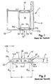
- Fig. 1 is a cross-sectional view of a composite profile shown extending in a longitudinal direction Z.
- the composite profile has two profile parts 31, 32, which are separated by a predetermined distance in a transverse direction X, which is perpendicular to the longitudinal direction Z.
- the profile parts 31, 32 are usually formed as metal profiles and preferably as aluminum profiles.
- the profile parts 31, 32 are by Isolierstege 10 'in Shock-resistant longitudinal direction Z and held in the transverse direction X at a distance and in a vertical direction Y perpendicular to the longitudinal direction Z and the transverse direction X relative to each other in position.
- composite profile 1 is limited by the use of two insulating bars 10 'and the profile parts 31, 32 a cavity 1h. In other composite profiles, not shown, only one insulating web 10 'may be provided for connecting the profile parts 31, 32.
- Fig. 2 is the in Fig. 1 shown conventional insulating bar 10 'shown enlarged.
- the Isoliersteg 10 ' extends in the longitudinal direction Z and in the transverse direction X over a predetermined width B and in the vertical direction Y over a predetermined height H.
- the insulating bar 10' has at its opposite in the transverse direction X outer edges (longitudinal edges) 21, 22 each have a curl body ( often also called rolling head) 25 on.
- the insulating web 25 shown is therefore a 2-head insulating web.
- Such a curl body 25 is formed as a bar complementary to the groove 31g, 32g, which extends in the longitudinal direction Z and has a predetermined cross-section perpendicular to the longitudinal direction Z.
- a recess 25k for an adhesive cord is provided on the respective outer sides.
- Such an adhesive cord recess 25k is optional and may be omitted.
- the insulating web 10 ' has the width B in the width direction X, wherein the curl body 25 each have a dimension b2 in the width direction X. This measure b2 is explained with reference to Fig. 3 will be explained in more detail.
- the insulating bar 10 ' has a height H in the vertical direction Y, wherein the Hohlkammem 10h have a height (inner height) h in the vertical direction Y.
- the height h of small hollow chambers is 10 mm or less.
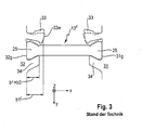
- Fig. 3 the design of the grooves 31 g, 32 g and the curl body 25 and the Anpressologicaln 33 and stop strips 34 shown in more detail.
- a conventional insulating bar 10 "is shown, and the description of the configuration of the grooves 31g, 32g and the rolling body 25 and the curling is the same as that of FIGS Fig. 1 and 2 .
- the groove 31g, 32g has a dimension (groove depth) b1 in the width direction X, which is determined by the height of the lower in the transverse direction X of the two strips 33, 34.
- the lower of the strips 33, 34 is usually the stop bar (often called anvil or shoulder) 34.
- the pressure bar (often called a hammer or roll-in hammer) 33 is from the in Fig. 3 shown in solid lines (with dimension b1 ') by plastic deformation in the in Fig. 3 Deformed with 33e and shown in dashed line position.
- the pressure strip 33 is designed so that the most projecting projection of the hammer 33 in the position 33 e is approximately as far in the transverse direction X from the bottom of the groove 31 g, 32g spaced, as corresponds to the dimension b1.
- the grooves 31g, 32g facing flanks of the Anpressance 33 and the stop bar 34 are usually inclined so that the groove narrows in the transverse direction X away from its bottom.
- the curling body 25 has in cross section XY perpendicular to the longitudinal direction Z a correspondingly adapted cross-section (here trapezoidal shape), so that a kind of dovetail connection is formed.
- a correspondingly adapted cross-section here trapezoidal shape
- sufficient clearance for insertion of the curl body 25 in the longitudinal direction Z is present in the groove.
- After deforming the Anpressance 33 in the designated 33e position of the curl body 25 is pressed between the Anpressance 33 and the stop bar 34 and held so shear resistant.
- This process and this design of the grooves and the rolling body is basically known.
- the Technoform standard groove is eg in the catalog mentioned above " Standard Profiles 2010 "on page 22 shown with dimensions.
- the dimension b1 is there for example 2.5 mm.
- configurations of the groove 31g, 32g the dimension b1 is correspondingly functionally determined so that the relevant for the shear-resistant clamping of the curl body measure is determined.
- the curling body 25 with the complementary dovetail shape usually has a dimension b2 in the transverse direction X which is approximately equal to the dimension b1, preferably slightly larger than the dimension b1.
- the dimension b2 of the curl body 25 may also be greater or smaller than the dimension b1.
- the measure b2 is functionally determined by the fact that it depends on the interaction of the groove and the curl body for shear-resistant holding the insulating web in the groove.
- the dimension b2 of the curl body 25 will usually be 2.5 mm or a little more, e.g. 2.6, 2.7, 2.8, 2.9 or 3.0 mm.
- each wall sections 10-4 delimiting the hollow chambers 10h in the direction of the curl body 25.
- the hollow chambers are each bounded by wall sections 10-2 and 10-3, which adjoin the wall sections 10-4.
- a partition wall 10-1 is provided between the two hollow chambers 10h.
- a 4-head insulating bar is an insulating bar, each with two Einroll stresses (curl heads) 25 on its opposite outer walls.
- the curled state of such a 4-head insulating web the exemplary in Fig. 1 of the EP 0 978 619 A2 is shown in the Fig. 2 of the DE 10 2009 037 851 A1 to see.
- Fig. 4 shows a first embodiment of an insulating web 20.
- the insulating web 20 has a first Isolierstegteil 23 and a second Isolierstegteil 24, which are connected via a hinge 28 which is formed in the present case as a film hinge.
- the first insulating web portion 23 has at its opposite outer edges 21b and 22b each have a curl body (curl head) 25.
- the second Isolierstegteil 24 has at its opposite outer edges 21a, 22a also each have a curl body (curl head) 25, so that the insulating web 20 a total of four curl body (curling heads) 25 has.
- the insulating bar 20 is therefore also referred to as a 4-head insulating bar.
- the walls of the first and second Isolierstegmaschine 23, 24, which connect the outer edges located curl body 25 are formed thin-walled.
- Thin-walled in this application means wall thicknesses in the range of 0.3 to 1.5 mm, preferably 0.5 to 1 mm, for example 0.5 mm, 0.6 mm, 0.7 mm, 0.8 mm, 0.9 mm, 1.0 mm.
- a hook fastener 27 is formed by a projection 27v provided on the first insulating piece part 23 and a hook projection 27h provided on the second insulating piece part 24.
- the hook closure 27 may also be formed by other hooks or by other suitable clip connections, so that it is generally possible to speak of a closure 27.
- a foam can be introduced into the hollow chamber 20h along the arrows K before closing the insulating web 20.
- this is a material which is introduced in liquid form into the hollow chamber 20h substantially in the direction of the arrow F, such as a 2K-PUR foam, which then foams in the hollow chamber and this fills as foam filling S (see Fig. 4b ).
- projections 29 are formed, which form a positive connection with the foam.
- these projections 29 are spherical, as in Fig. 4 , or formed as a barb or the like to form an engagement with the foam.
- this serves as a support foam and therefore allows the thin-walled portions 26 thinner than without the support foam S form.
- the exact dimensions are to be measured depending on the mechanical requirements and the density of the support foam and the material of the insulating bar.
- the width B of the insulating bars is in the range of 23 to 300 mm, preferably 30 to 150 mm, more preferably 40 to 100 mm.
- the height H of the Isolierstege is in the range of 10 to 200 mm, in particular 15 to 100 mm.
- the wall thicknesses of the thin-walled regions 26 are in the above-mentioned range.
- the thermal conductivity ⁇ of the heat-insulating foam material is in the range of 0.020 to 0.060 W / (mK), e.g. 0.025, 0.030, 0.035, 0.040, 0.045, 0.050, 0.055 W / (mK).
- the reaction time can be adapted to the manufacturing requirements, in particular in the 2K foam systems.
- the foams are to be chosen so that the best possible adhesion to the material of the insulating web is given and preferably a suitability for powder coating of the composite profiles provided with such insulating webs is given, i. an at least short-term heat resistance up to approx. 200 ° C.
- the foams are adapted to the fire behavior and have a good capacity to fill the cavity 20h.
- the foam contacting surfaces of the insulating bar may be required to prepare for better adhesion with the foam or adhesive. This can be done by blasting or knurling or applying a primer or the like.
- 1K or 2K adhesives of epoxy or PUR or acrylic or silicone or the like may be used, with 2K PUR.
- Systems preferably with a short-term temperature resistance of at least 180 to 200 ° C, are preferred.
- a double-sided tape can be used.
- Such a double-sided adhesive tape is preferably made of acrylic foam and in turn preferably has an at least short-term temperature resistance of about 180 to 200 ° C.
- the protrusions 29 are preferably arranged on the inner sides of the first and second Isolierstegmaschine 23 and 24 so that they extend substantially in the vertical direction Y, so as to optimize the heat conduction.
- the insulating web 20 may also be designed as a 2-head insulating web.
- the first modification of the first embodiment shown differs from this by the provision of openings O in the first insulating strip portion 23. These openings, which pass through the corresponding wall, in the case of the use of foam have the particular task, a pressure relief of the cavity 20h limiting Effect walls. The possibly excess foam S + can escape through the openings, so that there is no undesirable deformation of the insulating web 20.
- Fig. 6 is a second embodiment; the insulating web 20 shown.
- This is a 2-head insulating web, in the width direction X opposite outer edges only one curl body (curl head) 25 is provided.
- a split curl body 25 consisting of two parts 25a and 25b which are connectable via a closure 27 which is formed as a clip or catch connection 27 with a recess 27a and a projection 27v.
- This connection of the two parts 25a and 25b of the curl body simultaneously causes the closing of the cavity 20L.
- Fig. 4 and 5 shown embodiments may each have only one curl body 25 on the opposite sides in the width direction X. This can also be executed split, as it is in Fig. 6 is shown.
- Fig. 7 is a first modification of the second embodiment Fig. 6 shown. This in turn differs by the provision of passing through the wall of the first Isolierstegteils 23 openings. These have in turn, when using foam support, the task of escaping excess support foam S +. Furthermore are also at in Fig. 7 the modification already described features available and the modifications already described possible.
- a second modification of the second embodiment is shown, which differs from the previous embodiments essentially by the provision of a joint formed as a roller joint 28k.
- the first insulating web portion 23 and the second insulating web portion 24 are thus not integrally connected via a film hinge, but formed as separate parts, which are then connected via a positive roller joint 28k or are.
- the peculiarity of this modification is therefore that the insulating web has a two-parter, which are connected at a lateral in the width direction X side over the roller joint 28k and on the other side via a hook / clip connection 27.
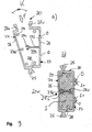
- Fig. 9 shows a third modification of the second embodiment, which is shown as a modification of the first modification.
- This differs essentially in that a support projection 29s is provided with a holding head 29c on the inner wall of the first Isolierstegteils 23 such that the holding head 29c positively engages with its recess and provided on the opposite side projection 29a holds.
- a wall which passes through the cavity 20h and connects the thin-walled portions 26 of the first and second insulating web portions 23 and 24 is thereby formed.
- This wall 29w which is produced by a clip connection of the holding head 29c with the projection 29a, has the particular advantage that at high temperatures, as occur for example in the powder coating, the thin-walled portions 26 are additionally supported and deformation better avoided can.
- Fig. 10 shows a fourth modification of the second embodiment, based on the second modification Fig. 8 based.
- the embodiment with the roller joint 28k with the Projection 29s and the holding head 29c provided.
- the functionality corresponds to that in Fig. 9b ) shown.
- roller joint 28k are positively connected to the insulating web, which is fastened on the laterally other side of the insulating web via a clip or hook connection.
- This can be like in Fig. 6 to 10 shown to be securable by curling.
- the roller joint 28k has an advantage because a large opening angle K or a complete separation of the two web parts, so for example of conductor bar and lid, for punching out openings in the conductor bar can be produced.
- the openings of the conductor bar can serve as discharge openings O when the corresponding cavity 20h is to be filled with foam.
Description
- Die Erfindung bezieht sich auf einen Isoliersteg für ein Verbundprofil für Fenster-, Türen- oder Fassedenelemente und auf ein Verfahren zum Herstellen eines solchen Isolierstegs und auf ein Verbundprofil mit einem solchen Isoliersteg.
- Isolierstege für wärmegedämmte Verbundprofile für Fenster-, Türen- oder Fassadenelemente und Verbundprofile mit solchen Isolierstegen sind im Stand der Technik bekannt (z.B.
DE 20 2007 016 649 U1 ). DieWO 97/09504 A1 DE 42 38 75.0 A1 , die in derWO 97/09504 A1 DE 42 38 750 A1 werden die Mehrkammerhohlprofile aus zwei Teilen mit unterschiedlichen Wandstärken hergestellt und beispielsweise verschweißt. - Aus der
EP 1 580 388 A2 und derDE in 2009 023 883 A1 sind jeweils Isolierstege mit einzelnen Hohlkammern bekannt, die aus jeweils zwei Isolierstegteilen zusammengefügt werden. Die beiden Isolierstegteile sind dabei so gestaltet, dass die jeweiligen Einrollkörper zum Einrollen in Nuten der Profilteile zweiteilig ausgebildet sind und zusammengesteckt werden können. Nach dem Einrollen werden die zusammengesteckten Isolierstegteile relativ zueinander in Position gehalten. Die Ausnehmungen und Vorsprünge zum Zusammenstecken liegen dabei auf einer Trennebene, die mittig durch die Einrollkörper verläuft und nach dem Zusammenstecken im Inneren des Einrollkörpers befindlich ist. - Aus der
EP 0 584 467 A1 sind langgestreckte Hohlprofile bekannt, die aus wenigstens zwei Teilprofilen, die separat extrudiert werden und dann zusammengefügt werden, bestehen. - Aus der
WO 2008/119535 A1 sind Isolierstege für Verbundprofile, Fenster-, Türen- oder Fassadenelemente bekannt, die sich in einer Längsrichtung erstrecken und bei denen der Isolierstegkörper durch die Wandung(en) des Isolierstegkörpers durchgehende Ausnehmungen aufweist, die durch leitersprossenartige Stege voneinander getrennt sind. Diese leiterartige Ausbildung ermöglicht eine begrenzte Längsverschiebbarkeit der Profilteile. Der Isoliersteg weist einen Deckel auf, der einstückig mit dem Isolierstegkörper ausgebildet ist und an dem Isolierstegkörper angeclipst werden kann und im eingeclipsten Zustand die Ausnehmungen vollständig abdeckt. - Isolierstege mit einer oder mehreren Hohlkammern und Verfahren zum Einbringen von Stützschaum in dieselben sind aus der
EP 0 978 619 A2 bekannt. Der Stützschaum wird dabei entweder stirnseitig eingebracht oder von zwei lateralen Seiten oder über laterale Öffnungen des Isolierstegs. Aus derEP 1 347 141 A1 sind ein Isoliersteg und ein Verfahren zur Herstellung eines solchen Isolierstegs ohne Volumenbegrenzung für den verwendeten Schaum bekannt. - Weitere Isolierstege und Verbundprofile mit Schäumen sind aus der
DE 100 35 649 A1 , derDE 100 39 980 A1 , derDE 10 2010 049 097 A1 , derWO 2011/032193 A2 und derWO 2005/008011 A1 bekannt. Rollladenprofile für Garagen oder Rolltore mit schaumgefüllten Kammern sind z.B. aus derEP 0 671 536 A1 , derDE 35 08 849 A1 und derDE 33 28 357 A1 bekannt. DieDE 30 33 206 A1 , dieFR 2 950 668 A1 DE 195 32 125 A1 offenbaren weitere Verbundprofile und Isolierstege. - Der genannte Stand der Technik ermöglicht es nicht, wenigstens teilweise dünnwandige Isolierstege für Verbundprofile aus Kunststoff mit einem Stützschaum in einfacher, kostengünstiger und sicherer Weise herzustellen. Probleme bestehen insbesondere auch bei der Pulverlackierung solcher Stege aus dem Stand der Technik und/oder beim Einbringen vom Schaum in Hohlkammerstege, insbesondere im Hinblick auf die einzuhaltende Maßhaltigkeit der resultierenden Isolierstege. Weiterhin ermöglicht der genannte Stand der Technik nicht, modular aufgebaute Isolierstege mit einfach herstellbaren, unterschiedlichen Funktionalitäten zu erhalten.
- Aufgabe der Erfindung ist es, den oben genannten Stand der Technik weiterzuentwickeln und die genannten Probleme mindestens teilweise zu lösen.
- Diese Aufgabe wird gelöst durch einen Isoliersteg nach Anspruch 1 bzw. ein Verfahren zur Herstellung eines solchen Isolierstegs nach Anspruch 7 bzw. ein Verbundprofil nach Anspruch 8.
- Weiterbildungen sind in den abhängigen Ansprüchen angegeben.
- Weitere Merkmale und Zweckmäßigkeiten ergeben sich aus der Beschreibung von Ausführungsbeispielen anhand der Figuren. Von den Figuren zeigen:
- Fig. 1
- eine Querschnittsansicht eines Verbundprofils mit herkömmlichen Hohlkammerisolierstegen;
- Fig. 2
- eine Querschnittsansicht eines Hohlkammerisolierstegs aus
Fig. 1 ; - Fig. 3
- eine Querschnittsansicht eines Details eines Verbundprofils mit zwei Profilteilen und einem herkömmlichen Isoliersteg, die durch Einrollen verbunden werden;
- Fig. 4
- einen Vier-Kopf-Isoliersteg nach einer ersten Ausführungsform;
- Fig. 5
- eine erste Modifikation der ersten Ausführungsform;
- Fig. 6
- einen Zwei-Kopf-Isoliersteg nach einer zweiten Ausführungsform;
- Fig. 7
- eine erste Modifikation der zweiten Ausführungsform;
- Fig. 8
- eine zweite Modifikation der zweiten Ausführungsform;
- Fig. 9
- eine dritte Modifikation der zweiten Ausführungsform; und
- Fig. 10
- eine vierte Modifikation der zweiten Ausführungsform.
- Es werden zunächst unter Bezugnahme auf die
Fig. 1 bis 3 die Merkmale von Verbundprofilen und Hohlkammerprofilen beschrieben, die im Stand der Technik bekannt und bei den hier beschriebenen Ausführungsformen vorhanden sind. - In
Fig. 1 ist eine Querschnittsansicht eines Verbundprofils dargestellt, das sich in einer Längsrichtung Z erstreckt. Das Verbundprofil weist zwei Profilteile 31, 32 auf, die in einer Querrichtung X, die senkrecht zu der Längsrichtung Z ist, um einen vorbestimmten Abstand voneinander getrennt sind. Die Profilteile 31, 32 sind üblicherweise als Metallprofile und bevorzugt als Aluminiumprofile ausgebildet. Die Profilteile 31, 32 werden durch Isolierstege 10' in Längsrichtung Z schubfest verbunden und in der Querrichtung X auf Abstand und in einer Höhenrichtung Y senkrecht zu der Längsrichtung Z und der Querrichtung X relativ zueinander in Position gehalten. Bei dem inFig. 1 gezeigten Verbundprofil 1 wird durch die Verwendung der zwei Isolierstege 10' und die Profilteile 31, 32 ein Hohlraum 1h begrenzt. Bei anderen, nicht dargestellten, Verbundprofilen kann auch nur ein Isoliersteg 10'zur Verbindung der Profilteile 31,32 vorgesehen sein. - In
Fig. 2 ist der inFig. 1 gezeigte herkömmliche Isoliersteg 10' vergrößert dargestellt. Der Isoliersteg 10' erstreckt sich in Längsrichtung Z und in Querrichtung X über eine vorbestimmte Breite B und in Höhenrichtung Y über eine vorbestimmte Höhe H. Der Isoliersteg 10' weist an seinen in Querrichtung X gegenüberliegenden Außenkanten (Längskanten) 21, 22 jeweils einen Einrollkörper (häufig auch Einrollkopf genannt) 25 auf. Der gezeigte Isoliersteg 25 ist daher ein 2-Kopf-Isoliersteg. Ein solcher Einrollkörper 25 ist als zu der Nut 31 g, 32g komplementäre Leiste, die sich in der Längsrichtung Z erstreckt und im Querschnitt senkrecht zu der Längsrichtung Z einen vorbestimmten Querschnitt aufweist, ausgebildet. Bei der inFig. 2 gezeigten Ausführungsform ist auf den jeweiligen Außenseiten eine Ausnehmung 25k für eine Klebeschnur vorgesehen. Eine solche Ausnehmung 25k für eine Klebeschnur ist optional und kann auch weggelassen werden. - Der Isoliersteg 10' weist die Breite B in Breitenrichtung X auf, wobei die Einrollkörper 25 jeweils ein Maß b2 in Breitenrichtung X aufweisen. Dieses Maß b2 wird unter Bezugnahme auf
Fig. 3 noch näher erläutert werden. Der Isoliersteg 10' weist eine Höhe H in Höhenrichtung Y auf, wobei die Hohlkammem 10h eine Höhe (Innenhöhe) h in Höhenrichtung Y aufweisen. Für Isolierstege 10' der gezeigten Art beträgt die Höhe h von kleinen Hohlkammern 10 mm oder weniger. - In
Fig. 3 ist die Gestaltung der Nuten 31 g, 32g und der Einrollkörper 25 sowie der Anpressleisten 33 und Anschlagsleisten 34 detaillierter dargestellt. Zur Vereinfachung der Erläuterung ist ein herkömmlicher Isoliersteg 10" dargestellt. Die Beschreibung der Gestaltung der Nuten 31g, 32g und Einrollkörper 25 sowie des Einrollens entspricht derjenigen aus denFig. 1 und 2 . Die Nut 31g, 32g, weist ein Maß (Nuttiefe) b1 in Breitenrichtung X auf, das durch die Höhe der in Querrichtung X niedrigeren der beiden Leisten 33, 34 bestimmt wird. Die niedrigere der Leisten 33, 34 ist üblicherweise die Anschlagsleiste (häufig auch Amboss oder Schulter genannt) 34. Die Anpressleiste (häufig auch Hammer oder Einrollhammer genannt) 33 wird aus der inFig. 3 in durchgezogenen Linien dargestellten Stellung (mit Maß b1') durch plastische Verformung in die inFig. 3 mit 33e bezeichnete und gestrichelt dargestellte Position verformt. Die Anpressleiste 33 ist dabei so gestaltet, dass der am weitesten vorstehende Vorsprung des Hammers 33 in der Stellung 33 e ungefähr so weit in Querrichtung X vom Boden der Nut 31 g, 32g beabstandet ist, wie dies dem Maß b1 entspricht. - Die der Nut 31g, 32g zugewandten Flanken der Anpressleiste 33 und der Anschlagsleiste 34 sind üblicherweise so geneigt, dass sich die Nut in Querrichtung X von ihrem Boden weg verengt.
- Der Einrollkörper 25 hat im Querschnitt X-Y senkrecht zu der Längsrichtung Z einen entsprechend angepassten Querschnitt (hier Trapezform), so dass eine Art Schwalbenschwanz-Verbindung gebildet wird. Vor dem Verformen der Anpressleiste 33 ist ein ausreichendes Spiel zum Einschieben der Einrollkörper 25 in Längsrichtung Z in die Nut vorhanden. Nach dem Verformen der Anpressleiste 33 in die mit 33e bezeichnete Stellung wird der Einrollkörper 25 zwischen die Anpressleiste 33 und die Anschlagsleiste 34 gedrückt und so schubfest gehalten. Dieser Vorgang und diese Gestaltung der Nuten und der Einrollkörper ist grundsätzlich bekannt. Die Technoform-Standardnut ist z.B. in dem eingangs genannten Katalog "Standard Profiles 2010" auf Seite 22 mit Bemaßung dargestellt. Das Maß b1 beträgt dort z.B. 2,5 mm. In anderen, hier nicht dargestellten, Gestaltungen der Nut 31g, 32g ist das Maß b1 entsprechend funktional so zu bestimmen, dass das für das schubfeste Festklemmen des Einrollkörpers relevante Maß bestimmt wird.
- Der Einrollkörper 25 mit der komplementären Schwalbenschwanz-Form weist üblicherweise in Querrichtung X ein Maß b2 auf, das ungefähr gleich dem Maß b1, vorzugsweise leicht größer als das Maß b1 ist. Abhängig von der Form der Nut und anderen Begebenheiten kann das Maß b2 des Einrollkörpers 25 auch größer oder kleiner als das Maß b1 sein. Auch hier ist wiederum im Einzelfall das Maß b2 funktional dadurch zu bestimmen, dass es auf das Zusammenwirken der Nut und des Einrollkörpers zum schubfesten Halten des Isolierstegs in der Nut ankommt. Für ein Maß b1 von 2,5 mm wird also das Maß b2 des Einrollkörpers 25 üblicherweise 2,5 mm oder etwas mehr, also z.B. 2,6, 2,7, 2,8, 2,9 oder 3,0 mm, betragen.
- Nochmals auf die
Fig. 1 und 2 und den dort gezeigten herkömmlichen Hohlkammerisoliersteg 10' Bezug nehmend, schließen sich an die Einrollkörper 25 jeweils Wandabschnitte 10-4 an, die die Hohlkammern 10h in Richtung der Einrollkörper 25 begrenzen. In Höhenrichtung Y werden die Hohlkammern jeweils von Wandabschnitten 10-2 und 10-3 begrenzt, die sich an die Wandabschnitte 10-4 anschließen. Bei der inFig. 1, 2 dargestellten Ausführung mit zwei Hohlkammern ist eine Trennwand 10-1 zwischen den beiden Hohlkammern 10h vorgesehen. - Ein 4-Kopf-Isoliersteg ist ein Isoliersteg mit jeweils zwei Einrollkörpern (Einrollköpfen) 25 an seinen gegenüberliegenden Außenwänden. Der eingerollte Zustand eines solchen 4-Kopf-Isolierstegs, der beispielhaft in
Fig. 1 derEP 0 978 619 A2 gezeigt ist, ist in derFig. 2 derDE 10 2009 037 851 A1 zu sehen. - Die oben unter Bezugnahme auf die
Fig. 1 bis 3 beschriebenen Merkmale der Verbundprofile und Isolierstege gelten auch für die nachfolgend beschriebenen Ausführungsformen der Erfindung, mit Ausnahme der beschriebenen Unterschiede der Ausführungsformen. Dieselben Bezugszeichen bezeichnen dabei dieselben Elemente/Merkmale und die Beschreibung wird aus Gründen der Vereinfachung nicht wiederholt. -
Fig. 4 zeigt eine erste Ausführungsform eines Isolierstegs 20. Der Isoliersteg 20 weist ein erstes Isolierstegteil 23 und ein zweites Isolierstegteil 24 auf, die über ein Gelenk 28, das im vorliegenden Fall als Filmscharnier ausgebildet ist, verbunden sind. Das erste Isolierstegteil 23 weist an seinen gegenüberliegenden Außenkanten 21b und 22b jeweils einen Einrollkörper (Einrollkopf) 25 auf. Das zweite Isolierstegteil 24 weist an seinen gegenüberliegenden Außenrändem 21a, 22a ebenfalls jeweils einen Einrollkörper (Einrollkopf) 25 auf, so dass der Isoliersteg 20 insgesamt vier Einrollkörper (Einrollköpfe) 25 aufweist. Der Isoliersteg 20 wird daher auch als 4-Kopf-Isoliersteg bezeichnet. Die Wände der ersten und zweiten Isolierstegteile 23, 24, die an den Außenrändern befindlichen Einrollkörper 25 verbinden, sind dünnwandig ausgebildet. Dünnwandig bedeutet in dieser Anmeldung Wanddicken im Bereich von 0,3 bis 1,5 mm, bevorzugt 0,5 bis 1 mm, z.B. 0,5 mm, 0,6 mm, 0,7 mm, 0,8 mm, 0,9 mm, 1,0 mm. Auf der dem Gelenk 28 in Breitenrichtung X gegenüberliegenden Seite ist ein Hakenverschluss 27 durch einen an dem ersten Isolierstegteil 23 vorgesehenen Vorsprung 27v und einen an dem zweiten Isolierstegteil 24 vorgesehenen Hakenvorsprung 27h ausgebildet. Der Hakenverschluss 27 kann auch durch andere Haken oder durch andere geeignete Clipsverbindungen ausgebildet sein, so dass allgemein von einem Verschluss 27 gesprochen werden kann. Wie aus dem Vergleich derFig. 4a ) und b) gut zu erkennen ist, umschließen die in einem Querschnitt X-Y senkrecht zur Längsrichtung Z im Wesentlichen wannenförmig oder U-förmig ausgebildeten ersten und zweiten Isolierstegteile 23 eine Hohlkammer 20h, die im Querschnitt X-Y im eingeclipsten/eingehakten Zustand des Verschlusses 27 vollständig geschlossen ist. - In dem in
Fig. 4a ) gezeigten, ungeschlossenen Zustand des Verschlusses 27 kann vor dem Zuklappen des Isolierstegs 20 entlang der Pfeile K ein Schaum in die Hohlkammer 20h eingebracht werden. Bevorzugt ist dieses ein Material, das in flüssiger Form in die Hohlkammer 20h im Wesentlichen in Richtung des Pfeiles F eingebracht wird, wie z.B. ein 2K-PUR-Schaum, der dann in der Hohlkammer aufschäumt und diese als Schaumfüllung S ausfüllt (sieheFig. 4b ). An der Innenseite der ersten und zweiten Isolierstegteile 23, 24, die dem Hohlraum zugewandt sind, sind Vorsprünge 29 ausgebildet, die eine formschlüssige Verbindung mit dem Schaum bilden. Vorzugsweise sind diese Vorsprünge 29 kugelförmig, wie inFig. 4 , oder als Widerhaken oder ähnliches unter Ausbildung eines Eingriffs mit dem Schaum ausgebildet. - Bei Füllung des Hohlraums 20h mit einem solchen Schaum, dient dieser als Stützschaum und ermöglicht daher die dünnwandigen Abschnitte 26 dünner als ohne den Stützschaum S auszubilden. Die genauen Abmessungen sind dabei abhängig von den mechanischen Anforderungen und der Dichte des Stützschaums sowie dem Material des Isolierstegs zu bemessen.
- Als Werkstoff für den Isoliersteg kommen Kunststoffe wie Polyamid, insbesondere Polyamid6.6, bevorzugt mit einer Glasfaserbeimischung im Bereich von 10 bis 40 %, bevorzugt 20 bis 30 %, z.B. PA66G25, oder PVC, bevorzugt mit Glasfaserbeimischung, oder ABS, oder Polypropylen (PP), bevorzugt mit einem Zusatz von Mineralpulver, oder PPO-PA, bevorzugt mit 5 bis 20 % Glasfaser (PPO = Polyphenylenoxid) oder PBT oder biobasierte PAs wie PA4.10, PA6.10, PA10.10 oder Blends derselben und andere für die Herstellung von Isolierstegen durch Extrusion geeignete Kunststoffe in Betracht.
- Die Breite B der Isolierstege liegt im Bereich von 23 bis 300 mm, bevorzugt 30 bis 150 mm, bevorzugter 40 bis 100 mm. Die Höhe H der Isolierstege liegt im Bereich von 10 bis 200 mm, insbesondere 15 bis 100 mm.
- Die Wanddicken der dünnwandigen Bereiche 26 liegen im oben genannten Bereich.
- Als Material für den Schaum sind organische wärmedämmende Materialien aus Hartschaum, Hartschäume aus Polystyrol, Phenolharz, PVC, PUR, besonders bevorzugt 2K-PUR (2K = 2 Komponenten), der in flüssiger Form in den Hohlraum 20h eingebracht wird und zu einem stabilen, zur Stützung des Isolierstegs geeigneten Schaum reagiert, andere 2K-Schaumsysteme, die im Verlauf der Reaktion eine Haftung zu dem Material des Isolierstegs entwickeln, das Einbringen von Hartschaumstreifen, die eingeklebt werden, und ähnliches geeignet. Die Wärmeleitfähigkeit λ des wärmedämmenden Schaummaterials liegt im Bereich von 0,020 bis 0,060 W/(mK), wie z.B. 0,025, 0,030, 0,035, 0,040, 0,045, 0,050, 0,055 W/(mK).
- Die Reaktionszeit ist insbesondere bei den 2K-Schaumsystemen an die Herstellungsnotwendigkeiten anpassbar. Die Schäume sind so zu wählen, dass möglichst gute Haftung zum Material des Isolierstegs gegeben ist und bevorzugt eine Eignung zur Pulverbeschichtung der mit solchen Isolierstegen gestellten Verbundprofile gegeben ist, d.h. eine mindestens kurzzeitige Wärmebeständigkeit bis ca. 200 °C. Die Schäume sind bezüglich des Brandverhaltens angepasst und weisen ein gutes Vermögen zum Füllen des Hohlraums 20h auf.
- Die mit dem Schaum in Kontakt kommenden Oberflächen des Isolierstegs sind gegebenenfalls für eine bessere Haftung mit dem Schaum oder einem Klebemittel vorzubereiten. Dieses kann durch Strahlen oder Rändeln oder Aufbringen eines Haftvermittlers oder ähnliches geschehen.
- Im Fall der Verwendung von Klebemitteln zur Herstellung der Verbindung zwischen dem Material des Isolierstegs und dem Schaum, insbesondere bei der Verwendung von Schaumstreifeneinsätzen, sind 1K- oder 2K-Klebstoffe aus Epoxy oder PUR oder Acryl oder Silikon oder ähnliches verwendbar, wobei 2K-PUR-Systeme, bevorzugt mit einer kurzzeitigen Temperaturbeständigkeit von wenigstens 180 bis 200 °C, bevorzugt werden. Alternativ kann auch ein Doppelklebeband verwendet werden. Ein solches Doppelklebeband ist bevorzugt aus Acrylschaum hergestellt und weist wiederum bevorzugt eine wenigstens kurzzeitige Temperaturbeständigkeit von ca. 180 bis 200°C auf.
- Die Vorsprünge 29 sind bevorzugt an den Innenseiten der ersten und zweiten Isolierstegteile 23 und 24 derart angeordnet, dass sie sich im Wesentlichen in Höhenrichtung Y erstrecken, um so die Wärmeleitung zu optimieren.
- Der Isoliersteg 20 kann auch als 2-Kopf-Isoliersteg ausgeführt sein.
- Alle hier genannten Merkmale sind in gleicher Weise auf die nachfolgend beschriebenen Modifikationen und Ausführungsformen anwendbar, außer es wird ausdrücklich etwas anderes erwähnt.
- Die in
Fig. 5 gezeigte erste Modifikation der ersten Ausführungsform unterscheidet sich von dieser durch das Vorsehen von Öffnungen O in dem ersten Isolierstegteil 23. Diese Öffnungen, die durch die entsprechende Wand hindurchgehen, haben im Fall der Verwendung von Schaum insbesondere die Aufgabe, eine Druckentlastung der den Hohlraum 20h begrenzenden Wände zu bewirken. Der eventuell überschüssige Schaum S+ kann durch die Öffnungen austreten, so dass es nicht zu einer unerwünschten Verformung des Isolierstegs 20 kommt. - In
Fig. 6 ist eine zweite Ausführungsform; des Isolierstegs 20 gezeigt. Dieser ist ein 2-Kopf-Isoliersteg, in Breitenrichtung X gegenüberliegenden Außenrändern jeweils nur ein Einrollkörper (Einrollkopf) 25 vorgesehen ist. Bei der gezeigten Ausführungsform ist auf einer Seite ein geteilter Einrollkörper 25, der aus zwei Teilen 25a und 25b besteht, die über einen Verschluss 27, der als eine Clips- oder Rastverbindung 27 mit einer Ausnehmung 27a und einem Vorsprung 27v ausgebildet ist, verbindbar sind. Diese Verbindung der beiden Teile 25a und 25b des Einrollkörpers bewirkt gleichzeitig das Schließen des Hohlraums 20L. Es versteht sich, dass auch die in denFig. 4 und5 gezeigten Ausführungsformen nur jeweils einen Einrollkörper 25 auf den in Breitenrichtung X gegenüberliegenden Seiten aufweisen können. Dieser kann auch geteilt ausgeführt sein, wie es inFig. 6 gezeigt ist. Natürlich ist es auch möglich, einen Haken- oder Clipsverschluss 27, wie er inFig. 5 gezeigt ist, und einen ungeteilten Einrollkörper 25 bei der Ausführungsform ausFig. 6 zu verwenden. Die übrigen Elemente und Merkmale derFig. 6 entsprechen den zu denFig. 4 und5 beschriebenen Merkmalen, so dass deren Beschreibung nicht wiederholt wird. - In
Fig. 7 ist eine erste Modifikation der zweiten Ausführungsform ausFig. 6 gezeigt. Diese unterscheidet sich wiederum durch das Vorsehen von durch die Wandung des ersten Isolierstegteils 23 hindurchgehenden Öffnungen. Diese haben wiederum, bei Verwendung von Stützschaum, die Aufgabe, überschüssigen Stützschaum S+ austreten zu lassen. Im Übrigen sind auch bei inFig. 7 gezeigten Modifikation die bereits beschriebenen Merkmale vorhanden und die bereits beschriebenen Modifikationen möglich. - In
Fig. 8 ist eine zweite Modifikation der zweiten Ausführungsform gezeigt, die sich im Wesentlichen durch das Vorsehen eines als Rollengelenk 28k ausgebildeten Gelenks von den vorherigen Ausführungsformen unterscheidet. Das erste Isolierstegteil 23 und das zweite Isolierstegteil 24 sind hier also nicht einstückig über ein Filmscharnier verbunden, sondern als getrennte Teile ausgebildet, die dann über ein formschlüssiges Rollengelenk 28k verbunden werden bzw. sind. Die Besonderheit dieser Modifikation liegt also darin, dass der Isoliersteg einen Zweiteiler aufweist, die an einer in Breitenrichtung X lateralen Seite über das Rollengelenk 28k und auf der anderen Seite über eine Haken-/Clipsverbindung 27 verbunden sind. Selbstverständlich ist es wie bei allen anderen Ausführungsformen auch möglich, andere Einrollkörper (Einrollköpfe) 25 vorzusehen, andere Clipsverbindungen vorzusehen oder auch eine 4-Kopf-Lösung vorzusehen. -
Fig. 9 zeigt eine dritte Modifikation der zweiten Ausführungsform, die als Modifikation der ersten Modifikation dargestellt ist. Diese unterscheidet sich im Wesentlichen dadurch, dass ein Stützvorsprung 29s mit einem Haltekopf 29c an der Innenwand des ersten Isolierstegteils 23 derart vorgesehen ist, dass der Haltekopf 29c mit seiner Ausnehmung einen an der gegenüberliegenden Seite vorgesehenen Vorsprung 29a formschlüssig ergreift und hält. Wie inFig. 9b gut zu erkennen ist, wird dadurch eine Wand, die den Hohlraum 20h durchquert und die dünnwandigen Abschnitte'26 der ersten und zweiten Isolierstegteile 23 und 24 verbindet, gebildet. Diese Wand 29w, die durch eine Clipsverbindung des Haltekopfs 29c mit dem Vorsprung 29a hergestellt wird, hat insbesondere den Vorteil, dass bei hohen Temperaturen, wie sie zum Beispiel bei der Pulverbeschichtung auftreten, die dünnwandigen Abschnitte 26 zusätzlich gestützt werden und eine Verformung besser vermieden werden kann. - Selbstverständlich sind auch hier wieder alle denkbaren Einrollkörper 25 in Form und Anzahl möglich. Auch alle anderen Merkmale und Modifikationen der zuvor beschriebenen Ausführungsformen sind anwendbar.
-
Fig. 10 zeigt eine vierte Modifikation der zweiten Ausführungsform, die auf der zweiten Modifikation ausFig. 8 basiert. Hier ist die Ausführungsform mit dem Rollengelenk 28k mit dem Vorsprung 29s und dem Haltekopf 29c versehen. Die Funktionsweise entspricht der inFig. 9b ) gezeigten. - Die in den Ausführungsformen gezeigte Technik ist auch auf ändere Isolierstege, die nicht gezeigt sind, anwendbar. Hier kann z.B. für einen schubweichen Isoliersteg, der als Leitersteg oder ähnliches ausgebildet ist, ein Deckel unter Verwendung des in den
Fig. 8 und 10 gezeigten Rollengelenks 28k formschlüssig mit dem Isoliersteg verbunden werden, der auf der lateral anderen Seite des Isolierstegs über eine Clips- oder Hakenverbindung befestigt wird. Diese kann wie inFig. 6 bis 10 gezeigt, durch Einrollen sicherbar sein. Auch und gerade in diesem Zusammenhang hat das Rollengelenk 28k einen Vorteil, da ein großer Öffnungswinkel K oder eine vollständige Trennung der beiden Stegteile, also zum Beispiel von Leitersteg und Deckel, zum Ausstanzen von Öffnungen in dem Leitersteg herstellbar ist. Außerdem können die Öffnungen des Leiterstegs als Entlastungsöffnungen O dienen, wenn der entsprechende Hohlraum 20h mit Schaum zu füllen ist. - Es wird ausdrücklich erklärt, dass alle Merkmale die in der Beschreibung und/oder den Ansprüchen offenbart sind, dazu gedacht sind, getrennt und unabhängig voneinander zum Zwecke der ursprünglichen Offenbarung und ebenso zum Zwecke des Beschränkens der beanspruchten Erfindung, unabhängig von der Zusammenstellung der Merkmale in den Ausführungsformen und/oder den Ansprüchen, offenbart zu werden. Es wird ausdrücklich erklärt, dass alle Wertebereiche oder Angaben von Gruppen von Gesamtheiten jeden möglichen Zwischenwert und jede Zwischengesamtheit zum Zwecke der ursprünglichen Offenbarung und ebenso zum Zwecke des Beschränkens der beanspruchten Erfindung offenbaren.
Claims (8)
- Isoliersteg (20) für ein Verbundprofil für Fenster-, Türen- oder Fassadenelemente, der sich in einer Längsrichtung (Z) erstreckt und zur Verbindung mit wenigstens einem Profilteil (31, 32) des Verbundprofils (1), das sich in der Längsrichtung (Z) erstreckt und wenigstens eine Einrollnut (31g, 32g) aufweist, angepasst ist, mit
einem ersten Isolierstegteil (23) und einem zweiten Isolierstegteil (24), die lateral in einer Breitenrichtung (X), die senkrecht zu der Längsrichtung (Z) ist, über ein Gelenk (28, 28k) verbunden sind, und die lateral auf der anderen Seite in der Breitenrichtung (X) durch einen Clips- oder Hakenverschluss (27) verbindbar sind, so dass im geschlossenen Zustand des Clips- oder Hakenverschlusses (27) eine Hohlkammer (20h), die im Querschnitt (X-Y) senkrecht zu der Längsrichtung (Z) geschlossen ist, gebildet wird, und
mindestens einem Einrollkörper (25) an den lateral in Breitenrichtung (X) gegenüberliegenden Außenrändern (21, 22) für ein Einrollen in die wenigstens eine Nut (31g, 32g) des wenigstens einen Profilteils (31, 32),
bei dem das Gelenk als Rollengelenk (28k) oder als Filmscharnier (28) ausgebildet ist. - Isoliersteg nach Anspruch 1, bei dem die sich in Querrichtung (X) erstreckenden Wände der ersten und zweiten Isolierstegteile wenigstens abschnittsweise dünnwandig ausgebildet sind.
- Isoliersteg nach Anspruch 1 oder 2, bei dem an den der Hohlkammer (20h) zugewandten Innenseiten der ersten und zweiten Isolierstegteile (23, 24) Formschlussvorsprünge (29), die sich in Höhenrichtung (Y) erstrecken, vorgesehen sind.
- Isoliersteg nach einem der Ansprüche 1 bis 3, bei dem wenigstens einer der Einrollkörper (25) als ein geteilter Einrollkörper (25, 25a, 25b) ausgebildet ist, dessen Teile (25a, 25b) durch das Einrollen des Einrollkörpers (25) fest verbunden und gesichert werden.
- Isoliersteg nach einem der Ansprüche 1 bis 4, bei dem die Hohlkammer (20h) wenigstens teilweise mit Schaum (S) gefüllt ist.
- Isoliersteg nach Anspruch 5, bei dem in dem ersten oder zweiten Isolierstegteil (23, 24) durch die Wandung des ersten oder zweiten Isolierstegteils (23, 24) hindurchgehende Öffnungen (O) vorgesehen sind, die den Austritt von überflüssigem Schaum zur Druckentlastung ermöglichen.
- Verfahren zur Herstellung eines Isolierstegs nach einem der Ansprüche 1 bis 6, bei der die Hohlkammer (20h) wenigstens teilweise mit Schaum gefüllt wird, indem eine flüssige aufschäumbare Substanz in die Hohlkammer (20h) bei geöffnetem Clips- oder Hakenverschluss (27) durch denselben hindurch eingebracht wird und der Schaum nach Schließen derselben durch Aufschäumen der flüssigen Substanz erzeugt wird.
- Verbundprofil für Fenster-, Türen- oder Fassadenelemente, das sich in einer Längsrichtung (Z) erstreckt, mit
wenigstens einem Profilteil (31, 32) und wenigstens einem Isoliersteg (20) nach einem der Ansprüche 1 bis 6, der mit dem Profilteil durch Einrollen verbunden ist.
Applications Claiming Priority (2)
| Application Number | Priority Date | Filing Date | Title |
|---|---|---|---|
| DE102012210393 | 2012-06-20 | ||
| PCT/EP2013/001830 WO2013189604A1 (de) | 2012-06-20 | 2013-06-20 | Isoliersteg für ein verbundprofil für fenster-, türen- oder fassadenelemente und verfahren zum herstellen eines solchen isolierstegs und verbundprofil mit einem solchen isoliersteg |
Publications (3)
| Publication Number | Publication Date |
|---|---|
| EP2864567A1 EP2864567A1 (de) | 2015-04-29 |
| EP2864567B1 true EP2864567B1 (de) | 2016-07-27 |
| EP2864567B2 EP2864567B2 (de) | 2019-10-09 |
Family
ID=48672561
Family Applications (1)
| Application Number | Title | Priority Date | Filing Date |
|---|---|---|---|
| EP13730811.0A Active EP2864567B2 (de) | 2012-06-20 | 2013-06-20 | Isoliersteg für ein verbundprofil für fenster-, türen- oder fassadenelemente und verfahren zum herstellen eines solchen isolierstegs und verbundprofil mit einem solchen isoliersteg |
Country Status (6)
| Country | Link |
|---|---|
| EP (1) | EP2864567B2 (de) |
| DE (1) | DE102013010336A1 (de) |
| ES (1) | ES2592861T5 (de) |
| PT (1) | PT2864567T (de) |
| SM (1) | SMT201600373B (de) |
| WO (1) | WO2013189604A1 (de) |
Families Citing this family (5)
| Publication number | Priority date | Publication date | Assignee | Title |
|---|---|---|---|---|
| DE202013010108U1 (de) * | 2013-11-08 | 2015-02-09 | Stefan Günthner | Kraftschlüssige Verbindung von Hartschaumwerkstoffen |
| DE102014108264A1 (de) * | 2014-06-12 | 2015-12-17 | Ensinger Gmbh | Wärmeisolierendes Abstandhalterprofil |
| DE102016113928A1 (de) * | 2016-07-28 | 2018-02-01 | Montag GmbH | Fenster |
| DE102016217622A1 (de) | 2016-09-15 | 2018-03-15 | Peri Gmbh | Kupplung |
| DE102016119580A1 (de) | 2016-10-13 | 2018-04-19 | Ensinger Gmbh | Kunststoffprofil für ein Metall-Kunststoff-Verbundprofil |
Citations (3)
| Publication number | Priority date | Publication date | Assignee | Title |
|---|---|---|---|---|
| WO2008119535A1 (de) | 2007-04-02 | 2008-10-09 | Technoform Caprano Und Brunnhofer Gmbh & Co. Kg | Leiterförmiger isoliersteg für ein verbundprofil für fenster-, türen- und fassadenelemente und verbundprofil für fenster-, türen- und fassadenelemente |
| WO2011012293A1 (de) | 2009-07-28 | 2011-02-03 | Technoform Caprano Und Brunnhofer Gmbh & Co. Kg | Isoliersteg |
| EP2559838A2 (de) | 2011-08-17 | 2013-02-20 | Technoform Bautec Holding GmbH | Lackierfähiger Isoliersteg für ein Verbundprofil für Fenster-, Türen-, oder Fassadenelemente und Verbundprofil mit demselben |
Family Cites Families (20)
| Publication number | Priority date | Publication date | Assignee | Title |
|---|---|---|---|---|
| DE3033206C2 (de) | 1980-09-03 | 1984-07-05 | Josef Gartner & Co, 8883 Gundelfingen | Verbundprofil |
| DE3328357A1 (de) | 1983-08-05 | 1985-02-14 | Kurt K. 7143 Vaihingen Proksch | Rolladenleiste |
| DE3508849A1 (de) | 1985-03-13 | 1986-09-25 | Günter 2800 Bremen Kindervater | Rolladenprofil sowie verfahren und vorrichtung zur herstellung desselben |
| DE4228336C2 (de) | 1992-08-26 | 1996-02-15 | Caprano & Brunnhofer | Langgestrecktes Hohlprofil aus thermoplastischem Kunststoff und Verfahren zur kontinuierlichen Herstellung eines langgestreckten Hohlprofils |
| DE4238750C2 (de) | 1992-11-17 | 1995-09-14 | Wicona Bausysteme Gmbh | Wärmegedämmtes Verbundprofil |
| DE59407341D1 (de) | 1994-03-08 | 1999-01-07 | Grashei F Alukon Kg | Rolladen-Profil, insbesondere für Garagen- oder Rolltore |
| CH690452A5 (de) | 1995-07-05 | 2000-09-15 | Kronenberger Ag | Isolationsvorrichtung zur thermischen Trennung von Leichtmetallprofilen im Fensterbau. |
| ATE232936T1 (de) | 1995-09-05 | 2003-03-15 | Norsk Hydro As | Wärmegedämmtes verbundprofil |
| DE19835439A1 (de) | 1998-08-05 | 2000-02-17 | Pitscheider Ingenieurbuero Dr | Hohldämmleiste |
| DE10035649A1 (de) | 2000-07-20 | 2002-01-31 | Bayer Ag | Fensterprofil mit verbesserter Wärmeisolation und Maßhaltigkeit |
| DE10039980A1 (de) | 2000-08-16 | 2002-02-28 | Harald Schulz | Hohldämmleiste mit geschäumtem Kunststoff |
| DE10212452A1 (de) | 2002-03-20 | 2003-10-02 | Schueco Int Kg | Verfahren zur Herstellung eines wärmedämmenden Isolier- und Verbindungssteges und nach diesem Verfahren hergestellter Isolier- und Verbindungssteg |
| DE10331382A1 (de) | 2003-07-11 | 2005-02-03 | SCHÜCO International KG | Verbundprofil mit Isoliersteg, insbesondere für Fenster, Türen und Fassaden |
| ITMI20040552A1 (it) | 2004-03-23 | 2004-06-23 | Norsk Hydro As | Corpo termoisolante per un profilato a taglio termico per serramenti o simili |
| DE102009023883B4 (de) | 2009-06-04 | 2019-01-24 | Schindler Fenster + Fassaden Gmbh | Fassadenelement |
| DE102009037851A1 (de) | 2009-08-18 | 2011-02-24 | Technoform Caprano Und Brunnhofer Gmbh & Co. Kg | Mehrteiliger Isolierkörper zur thermischen Trennung in Profilen für Fenster-, Türen- und Fassadenelemente, Profil für Fenster-, Türen- und Fassadenelemente sowie Herstellungsverfahren für den Isolierkörper und das Profil |
| AT508870B1 (de) | 2009-09-16 | 2015-11-15 | Alutechnik Matauschek Gmbh | Isolierteil |
| FR2950668B1 (fr) | 2009-09-25 | 2011-12-16 | Sapa Building System | Profile en matiere plastique |
| DE102010049097A1 (de) | 2010-10-21 | 2012-04-26 | Rehau Ag + Co | Verfahren zur Einbringung von Schaummaterial in Hohlkammerprofile sowie Hohlkammerprofil |
| DE202012010135U1 (de) * | 2012-10-23 | 2012-11-22 | Technoform Bautec Holding Gmbh | Isoliersteg für ein Verbundprofil für Fenster-, Türen- oder Fasadenelemente und Verbundprofil für Fenster-, Türen- oder Fassadenelemente mit Isoliersteg |
-
2013
- 2013-06-20 ES ES13730811T patent/ES2592861T5/es active Active
- 2013-06-20 WO PCT/EP2013/001830 patent/WO2013189604A1/de active Application Filing
- 2013-06-20 DE DE102013010336A patent/DE102013010336A1/de not_active Withdrawn
- 2013-06-20 EP EP13730811.0A patent/EP2864567B2/de active Active
- 2013-06-20 PT PT137308110T patent/PT2864567T/pt unknown
-
2016
- 2016-10-14 SM SM201600373T patent/SMT201600373B/it unknown
Patent Citations (3)
| Publication number | Priority date | Publication date | Assignee | Title |
|---|---|---|---|---|
| WO2008119535A1 (de) | 2007-04-02 | 2008-10-09 | Technoform Caprano Und Brunnhofer Gmbh & Co. Kg | Leiterförmiger isoliersteg für ein verbundprofil für fenster-, türen- und fassadenelemente und verbundprofil für fenster-, türen- und fassadenelemente |
| WO2011012293A1 (de) | 2009-07-28 | 2011-02-03 | Technoform Caprano Und Brunnhofer Gmbh & Co. Kg | Isoliersteg |
| EP2559838A2 (de) | 2011-08-17 | 2013-02-20 | Technoform Bautec Holding GmbH | Lackierfähiger Isoliersteg für ein Verbundprofil für Fenster-, Türen-, oder Fassadenelemente und Verbundprofil mit demselben |
Non-Patent Citations (1)
| Title |
|---|
| ANONYMOUS: "Kniegelenk", WIKIPEDIA, 19 May 2018 (2018-05-19), pages 1 - 12, XP055602900, Retrieved from the Internet <URL:https://de.wikipedia.org/w/index.php?title=Kniegelenk&oldid=177556447> [retrieved on 20180927] |
Also Published As
| Publication number | Publication date |
|---|---|
| EP2864567A1 (de) | 2015-04-29 |
| PT2864567T (pt) | 2016-10-26 |
| DE102013010336A1 (de) | 2013-12-24 |
| ES2592861T3 (es) | 2016-12-01 |
| WO2013189604A1 (de) | 2013-12-27 |
| EP2864567B2 (de) | 2019-10-09 |
| SMT201600373B (it) | 2016-11-10 |
| ES2592861T5 (es) | 2020-04-30 |
Similar Documents
| Publication | Publication Date | Title |
|---|---|---|
| EP2106491B2 (de) | Kunststoffprofil für fenster-, türen- und fassadenelemente | |
| EP2864567B1 (de) | Isoliersteg für ein verbundprofil für fenster-, türen- oder fassadenelemente und verfahren zum herstellen eines solchen isolierstegs und verbundprofil mit einem solchen isoliersteg | |
| EP0802300A2 (de) | Rahmenwerk aus Metallprofilen in Brandschutzausführung für Fenster, Türen, Fassaden oder Glasdächer | |
| EP2920392B1 (de) | Isoliersteg für ein verbundprofil für fenster-, türen- oder fassadenelemente und verbundprofil für fenster-, türen- oder fassadenelemente mit isoliersteg | |
| DE102006059854A1 (de) | Armiertes Kunststoffprofil für Fenster-, Türen- und Fassadenelemente | |
| DE102012101668A1 (de) | Verfahren zur Erstellung eines Hohlkammerprofils | |
| EP2576949B1 (de) | Thermisch getrenntes profil | |
| EP2432960B1 (de) | Isoliersteg | |
| DE102013204693A1 (de) | Dämmsteg für wärmegedämmte Metall-Kunststoff-Verbundprofile mit über der Dämmsteglänge veränderlicher Schubtragfähigkeit sowie wärmegedämmtes Verbundprofil | |
| AT9079U1 (de) | Bauelement und verwendung eines trägers sowie verfahren zur herstellung eines fassadenelementes | |
| EP0828052B1 (de) | Hohlprofil, insbesondere aus Kunststoff mit Wärmeisolationsmittel | |
| DE102010064034A1 (de) | Isolierstab für Verbundprofil von Bauelementen | |
| WO2014005717A1 (de) | Isoliersteg für ein verbundprofil für fenster-, türen- oder fassadenelemente und verbundprofil für fenster-, türen- oder fassadenelemente mit isoliersteg | |
| DE102015007611A1 (de) | Isolierelement | |
| EP2406454A1 (de) | Abstandshalter für isolierglasscheiben | |
| DE102008020988A1 (de) | Wärmeisolierendes Rahmenprofil für die Herstellung von Tür- und Fensterrahmen | |
| DE19953133A1 (de) | Rahmen und Verfahren zur Herstellung dieses Rahmens | |
| DE102012010900B4 (de) | Verbundprofil für Fenster-, Türen oder Fassadenelemente und Isoliersteg für ein solches Verbundprofil | |
| EP2573307A1 (de) | Mehrteiliges Profilrahmensytem für Türen, Tore, Wintergärten und Fenster | |
| DE2412317A1 (de) | Verfahren zur herstellung eines verbundprofils, insbesondere fuer fenster- bzw. tuerrahmen oder aehnliche bauteile | |
| EP1837095A2 (de) | Metallprofil für Rahmenkonstruktionen von Fenster-, Tür- oder Fassadenelementen sowie Verfahren zur Herstellung desselben | |
| DE102015112154A1 (de) | Verfahren zur Herstellung eines Dämmelements sowie ein entsprechendes Dämmelement | |
| EP2199518A1 (de) | Wärmegedämmtes Verbundprofiel und Verfahren zu dessen Herstellung | |
| DE202006019361U1 (de) | Kunststoffprofil für Fenster-, Türen- und Fassadenelemente |
Legal Events
| Date | Code | Title | Description |
|---|---|---|---|
| PUAI | Public reference made under article 153(3) epc to a published international application that has entered the european phase |
Free format text: ORIGINAL CODE: 0009012 |
|
| 17P | Request for examination filed |
Effective date: 20150119 |
|
| AK | Designated contracting states |
Kind code of ref document: A1 Designated state(s): AL AT BE BG CH CY CZ DE DK EE ES FI FR GB GR HR HU IE IS IT LI LT LU LV MC MK MT NL NO PL PT RO RS SE SI SK SM TR |
|
| AX | Request for extension of the european patent |
Extension state: BA ME |
|
| DAX | Request for extension of the european patent (deleted) | ||
| GRAP | Despatch of communication of intention to grant a patent |
Free format text: ORIGINAL CODE: EPIDOSNIGR1 |
|
| INTG | Intention to grant announced |
Effective date: 20160203 |
|
| GRAS | Grant fee paid |
Free format text: ORIGINAL CODE: EPIDOSNIGR3 |
|
| GRAR | Information related to intention to grant a patent recorded |
Free format text: ORIGINAL CODE: EPIDOSNIGR71 |
|
| GRAA | (expected) grant |
Free format text: ORIGINAL CODE: 0009210 |
|
| AK | Designated contracting states |
Kind code of ref document: B1 Designated state(s): AL AT BE BG CH CY CZ DE DK EE ES FI FR GB GR HR HU IE IS IT LI LT LU LV MC MK MT NL NO PL PT RO RS SE SI SK SM TR |
|
| INTG | Intention to grant announced |
Effective date: 20160621 |
|
| REG | Reference to a national code |
Ref country code: GB Ref legal event code: FG4D Free format text: NOT ENGLISH |
|
| REG | Reference to a national code |
Ref country code: CH Ref legal event code: EP |
|
| REG | Reference to a national code |
Ref country code: AT Ref legal event code: REF Ref document number: 815954 Country of ref document: AT Kind code of ref document: T Effective date: 20160815 |
|
| REG | Reference to a national code |
Ref country code: IE Ref legal event code: FG4D Free format text: LANGUAGE OF EP DOCUMENT: GERMAN |
|
| REG | Reference to a national code |
Ref country code: DE Ref legal event code: R096 Ref document number: 502013003890 Country of ref document: DE |
|
| REG | Reference to a national code |
Ref country code: CH Ref legal event code: NV Representative=s name: E. BLUM AND CO. AG PATENT- UND MARKENANWAELTE , CH |
|
| REG | Reference to a national code |
Ref country code: PT Ref legal event code: SC4A Ref document number: 2864567 Country of ref document: PT Date of ref document: 20161026 Kind code of ref document: T Free format text: AVAILABILITY OF NATIONAL TRANSLATION Effective date: 20161018 |
|
| REG | Reference to a national code |
Ref country code: LT Ref legal event code: MG4D |
|
| REG | Reference to a national code |
Ref country code: NL Ref legal event code: MP Effective date: 20160727 |
|
| REG | Reference to a national code |
Ref country code: ES Ref legal event code: FG2A Ref document number: 2592861 Country of ref document: ES Kind code of ref document: T3 Effective date: 20161201 |
|
| PG25 | Lapsed in a contracting state [announced via postgrant information from national office to epo] |
Ref country code: NO Free format text: LAPSE BECAUSE OF FAILURE TO SUBMIT A TRANSLATION OF THE DESCRIPTION OR TO PAY THE FEE WITHIN THE PRESCRIBED TIME-LIMIT Effective date: 20161027 Ref country code: FI Free format text: LAPSE BECAUSE OF FAILURE TO SUBMIT A TRANSLATION OF THE DESCRIPTION OR TO PAY THE FEE WITHIN THE PRESCRIBED TIME-LIMIT Effective date: 20160727 Ref country code: NL Free format text: LAPSE BECAUSE OF FAILURE TO SUBMIT A TRANSLATION OF THE DESCRIPTION OR TO PAY THE FEE WITHIN THE PRESCRIBED TIME-LIMIT Effective date: 20160727 Ref country code: RS Free format text: LAPSE BECAUSE OF FAILURE TO SUBMIT A TRANSLATION OF THE DESCRIPTION OR TO PAY THE FEE WITHIN THE PRESCRIBED TIME-LIMIT Effective date: 20160727 Ref country code: LT Free format text: LAPSE BECAUSE OF FAILURE TO SUBMIT A TRANSLATION OF THE DESCRIPTION OR TO PAY THE FEE WITHIN THE PRESCRIBED TIME-LIMIT Effective date: 20160727 Ref country code: HR Free format text: LAPSE BECAUSE OF FAILURE TO SUBMIT A TRANSLATION OF THE DESCRIPTION OR TO PAY THE FEE WITHIN THE PRESCRIBED TIME-LIMIT Effective date: 20160727 Ref country code: IS Free format text: LAPSE BECAUSE OF FAILURE TO SUBMIT A TRANSLATION OF THE DESCRIPTION OR TO PAY THE FEE WITHIN THE PRESCRIBED TIME-LIMIT Effective date: 20161127 |
|
| PG25 | Lapsed in a contracting state [announced via postgrant information from national office to epo] |
Ref country code: GR Free format text: LAPSE BECAUSE OF FAILURE TO SUBMIT A TRANSLATION OF THE DESCRIPTION OR TO PAY THE FEE WITHIN THE PRESCRIBED TIME-LIMIT Effective date: 20161028 Ref country code: LV Free format text: LAPSE BECAUSE OF FAILURE TO SUBMIT A TRANSLATION OF THE DESCRIPTION OR TO PAY THE FEE WITHIN THE PRESCRIBED TIME-LIMIT Effective date: 20160727 Ref country code: PL Free format text: LAPSE BECAUSE OF FAILURE TO SUBMIT A TRANSLATION OF THE DESCRIPTION OR TO PAY THE FEE WITHIN THE PRESCRIBED TIME-LIMIT Effective date: 20160727 Ref country code: SE Free format text: LAPSE BECAUSE OF FAILURE TO SUBMIT A TRANSLATION OF THE DESCRIPTION OR TO PAY THE FEE WITHIN THE PRESCRIBED TIME-LIMIT Effective date: 20160727 |
|
| REG | Reference to a national code |
Ref country code: DE Ref legal event code: R026 Ref document number: 502013003890 Country of ref document: DE |
|
| PG25 | Lapsed in a contracting state [announced via postgrant information from national office to epo] |
Ref country code: EE Free format text: LAPSE BECAUSE OF FAILURE TO SUBMIT A TRANSLATION OF THE DESCRIPTION OR TO PAY THE FEE WITHIN THE PRESCRIBED TIME-LIMIT Effective date: 20160727 Ref country code: RO Free format text: LAPSE BECAUSE OF FAILURE TO SUBMIT A TRANSLATION OF THE DESCRIPTION OR TO PAY THE FEE WITHIN THE PRESCRIBED TIME-LIMIT Effective date: 20160727 |
|
| PG25 | Lapsed in a contracting state [announced via postgrant information from national office to epo] |
Ref country code: SK Free format text: LAPSE BECAUSE OF FAILURE TO SUBMIT A TRANSLATION OF THE DESCRIPTION OR TO PAY THE FEE WITHIN THE PRESCRIBED TIME-LIMIT Effective date: 20160727 Ref country code: CZ Free format text: LAPSE BECAUSE OF FAILURE TO SUBMIT A TRANSLATION OF THE DESCRIPTION OR TO PAY THE FEE WITHIN THE PRESCRIBED TIME-LIMIT Effective date: 20160727 Ref country code: BG Free format text: LAPSE BECAUSE OF FAILURE TO SUBMIT A TRANSLATION OF THE DESCRIPTION OR TO PAY THE FEE WITHIN THE PRESCRIBED TIME-LIMIT Effective date: 20161027 Ref country code: DK Free format text: LAPSE BECAUSE OF FAILURE TO SUBMIT A TRANSLATION OF THE DESCRIPTION OR TO PAY THE FEE WITHIN THE PRESCRIBED TIME-LIMIT Effective date: 20160727 |
|
| PLAX | Notice of opposition and request to file observation + time limit sent |
Free format text: ORIGINAL CODE: EPIDOSNOBS2 |
|
| 26 | Opposition filed |
Opponent name: ENSINGER GMBH Effective date: 20170427 |
|
| PLBI | Opposition filed |
Free format text: ORIGINAL CODE: 0009260 |
|
| REG | Reference to a national code |
Ref country code: FR Ref legal event code: PLFP Year of fee payment: 5 |
|
| PG25 | Lapsed in a contracting state [announced via postgrant information from national office to epo] |
Ref country code: SI Free format text: LAPSE BECAUSE OF FAILURE TO SUBMIT A TRANSLATION OF THE DESCRIPTION OR TO PAY THE FEE WITHIN THE PRESCRIBED TIME-LIMIT Effective date: 20160727 |
|
| PLBB | Reply of patent proprietor to notice(s) of opposition received |
Free format text: ORIGINAL CODE: EPIDOSNOBS3 |
|
| PG25 | Lapsed in a contracting state [announced via postgrant information from national office to epo] |
Ref country code: MC Free format text: LAPSE BECAUSE OF FAILURE TO SUBMIT A TRANSLATION OF THE DESCRIPTION OR TO PAY THE FEE WITHIN THE PRESCRIBED TIME-LIMIT Effective date: 20160727 |
|
| REG | Reference to a national code |
Ref country code: IE Ref legal event code: MM4A |
|
| PG25 | Lapsed in a contracting state [announced via postgrant information from national office to epo] |
Ref country code: IE Free format text: LAPSE BECAUSE OF NON-PAYMENT OF DUE FEES Effective date: 20170620 Ref country code: LU Free format text: LAPSE BECAUSE OF NON-PAYMENT OF DUE FEES Effective date: 20170620 |
|
| REG | Reference to a national code |
Ref country code: FR Ref legal event code: PLFP Year of fee payment: 6 |
|
| PG25 | Lapsed in a contracting state [announced via postgrant information from national office to epo] |
Ref country code: MT Free format text: LAPSE BECAUSE OF FAILURE TO SUBMIT A TRANSLATION OF THE DESCRIPTION OR TO PAY THE FEE WITHIN THE PRESCRIBED TIME-LIMIT Effective date: 20160727 |
|
| PG25 | Lapsed in a contracting state [announced via postgrant information from national office to epo] |
Ref country code: AL Free format text: LAPSE BECAUSE OF FAILURE TO SUBMIT A TRANSLATION OF THE DESCRIPTION OR TO PAY THE FEE WITHIN THE PRESCRIBED TIME-LIMIT Effective date: 20160727 |
|
| PG25 | Lapsed in a contracting state [announced via postgrant information from national office to epo] |
Ref country code: SM Free format text: LAPSE BECAUSE OF NON-PAYMENT OF DUE FEES Effective date: 20190103 |
|
| PG25 | Lapsed in a contracting state [announced via postgrant information from national office to epo] |
Ref country code: HU Free format text: LAPSE BECAUSE OF FAILURE TO SUBMIT A TRANSLATION OF THE DESCRIPTION OR TO PAY THE FEE WITHIN THE PRESCRIBED TIME-LIMIT; INVALID AB INITIO Effective date: 20130620 |
|
| REG | Reference to a national code |
Ref country code: AT Ref legal event code: MM01 Ref document number: 815954 Country of ref document: AT Kind code of ref document: T Effective date: 20180620 |
|
| PUAH | Patent maintained in amended form |
Free format text: ORIGINAL CODE: 0009272 |
|
| STAA | Information on the status of an ep patent application or granted ep patent |
Free format text: STATUS: PATENT MAINTAINED AS AMENDED |
|
| REG | Reference to a national code |
Ref country code: CH Ref legal event code: AELC |
|
| 27A | Patent maintained in amended form |
Effective date: 20191009 |
|
| AK | Designated contracting states |
Kind code of ref document: B2 Designated state(s): AL AT BE BG CH CY CZ DE DK EE ES FI FR GB GR HR HU IE IS IT LI LT LU LV MC MK MT NL NO PL PT RO RS SE SI SK SM TR |
|
| REG | Reference to a national code |
Ref country code: DE Ref legal event code: R102 Ref document number: 502013003890 Country of ref document: DE |
|
| PG25 | Lapsed in a contracting state [announced via postgrant information from national office to epo] |
Ref country code: CY Free format text: LAPSE BECAUSE OF FAILURE TO SUBMIT A TRANSLATION OF THE DESCRIPTION OR TO PAY THE FEE WITHIN THE PRESCRIBED TIME-LIMIT Effective date: 20160727 |
|
| PG25 | Lapsed in a contracting state [announced via postgrant information from national office to epo] |
Ref country code: MK Free format text: LAPSE BECAUSE OF FAILURE TO SUBMIT A TRANSLATION OF THE DESCRIPTION OR TO PAY THE FEE WITHIN THE PRESCRIBED TIME-LIMIT Effective date: 20160727 |
|
| PG25 | Lapsed in a contracting state [announced via postgrant information from national office to epo] |
Ref country code: AT Free format text: LAPSE BECAUSE OF NON-PAYMENT OF DUE FEES Effective date: 20180620 |
|
| PG25 | Lapsed in a contracting state [announced via postgrant information from national office to epo] |
Ref country code: TR Free format text: LAPSE BECAUSE OF FAILURE TO SUBMIT A TRANSLATION OF THE DESCRIPTION OR TO PAY THE FEE WITHIN THE PRESCRIBED TIME-LIMIT Effective date: 20160727 |
|
| REG | Reference to a national code |
Ref country code: ES Ref legal event code: DC2A Ref document number: 2592861 Country of ref document: ES Kind code of ref document: T5 Effective date: 20200430 |
|
| REG | Reference to a national code |
Ref country code: DE Ref legal event code: R081 Ref document number: 502013003890 Country of ref document: DE Owner name: TECHNOFORM BAUTEC HOLDING GMBH, DE Free format text: FORMER OWNER: TECHNOFORM BAUTEC HOLDING GMBH, 34117 KASSEL, DE |
|
| PGFP | Annual fee paid to national office [announced via postgrant information from national office to epo] |
Ref country code: PT Payment date: 20230620 Year of fee payment: 11 Ref country code: FR Payment date: 20230622 Year of fee payment: 11 Ref country code: DE Payment date: 20230602 Year of fee payment: 11 |
|
| PGFP | Annual fee paid to national office [announced via postgrant information from national office to epo] |
Ref country code: BE Payment date: 20230619 Year of fee payment: 11 |
|
| PGFP | Annual fee paid to national office [announced via postgrant information from national office to epo] |
Ref country code: IT Payment date: 20230630 Year of fee payment: 11 Ref country code: GB Payment date: 20230622 Year of fee payment: 11 Ref country code: ES Payment date: 20230719 Year of fee payment: 11 Ref country code: CH Payment date: 20230702 Year of fee payment: 11 |