EP2864125B1 - Walzengeführtes duplex-thermodrucksystem - Google Patents
Walzengeführtes duplex-thermodrucksystem Download PDFInfo
- Publication number
- EP2864125B1 EP2864125B1 EP13732770.6A EP13732770A EP2864125B1 EP 2864125 B1 EP2864125 B1 EP 2864125B1 EP 13732770 A EP13732770 A EP 13732770A EP 2864125 B1 EP2864125 B1 EP 2864125B1
- Authority
- EP
- European Patent Office
- Prior art keywords
- thermal
- receiver
- printing
- donor
- roll
- Prior art date
- Legal status (The legal status is an assumption and is not a legal conclusion. Google has not performed a legal analysis and makes no representation as to the accuracy of the status listed.)
- Active
Links
- 238000007651 thermal printing Methods 0.000 title claims description 42
- 238000007639 printing Methods 0.000 claims description 89
- 238000001931 thermography Methods 0.000 claims description 46
- 238000012546 transfer Methods 0.000 claims description 14
- 239000003086 colorant Substances 0.000 claims description 13
- 239000000463 material Substances 0.000 claims description 13
- 239000000758 substrate Substances 0.000 claims description 9
- 239000011253 protective coating Substances 0.000 claims description 2
- 238000004804 winding Methods 0.000 claims description 2
- 238000010586 diagram Methods 0.000 description 16
- 238000000034 method Methods 0.000 description 14
- 230000007246 mechanism Effects 0.000 description 13
- 238000013459 approach Methods 0.000 description 5
- 238000005520 cutting process Methods 0.000 description 5
- 230000003213 activating effect Effects 0.000 description 4
- 238000004891 communication Methods 0.000 description 4
- 239000000919 ceramic Substances 0.000 description 3
- 239000002699 waste material Substances 0.000 description 3
- 238000013461 design Methods 0.000 description 2
- 238000010438 heat treatment Methods 0.000 description 2
- 230000003287 optical effect Effects 0.000 description 2
- 238000009966 trimming Methods 0.000 description 2
- XAGFODPZIPBFFR-UHFFFAOYSA-N aluminium Chemical class [Al] XAGFODPZIPBFFR-UHFFFAOYSA-N 0.000 description 1
- 229910052782 aluminium Inorganic materials 0.000 description 1
- 239000011248 coating agent Substances 0.000 description 1
- 238000000576 coating method Methods 0.000 description 1
- 238000011109 contamination Methods 0.000 description 1
- 238000013500 data storage Methods 0.000 description 1
- 239000000428 dust Substances 0.000 description 1
- 230000000694 effects Effects 0.000 description 1
- 238000005516 engineering process Methods 0.000 description 1
- 230000007613 environmental effect Effects 0.000 description 1
- 238000003384 imaging method Methods 0.000 description 1
- 230000003993 interaction Effects 0.000 description 1
- 230000005019 pattern of movement Effects 0.000 description 1
- 238000003825 pressing Methods 0.000 description 1
- 230000001681 protective effect Effects 0.000 description 1
- 239000000565 sealant Substances 0.000 description 1
- 239000007787 solid Substances 0.000 description 1
- 230000005236 sound signal Effects 0.000 description 1
- 238000000859 sublimation Methods 0.000 description 1
- 230000008022 sublimation Effects 0.000 description 1
- 230000000007 visual effect Effects 0.000 description 1
Images


Classifications
-
- B—PERFORMING OPERATIONS; TRANSPORTING
- B41—PRINTING; LINING MACHINES; TYPEWRITERS; STAMPS
- B41J—TYPEWRITERS; SELECTIVE PRINTING MECHANISMS, i.e. MECHANISMS PRINTING OTHERWISE THAN FROM A FORME; CORRECTION OF TYPOGRAPHICAL ERRORS
- B41J3/00—Typewriters or selective printing or marking mechanisms characterised by the purpose for which they are constructed
- B41J3/60—Typewriters or selective printing or marking mechanisms characterised by the purpose for which they are constructed for printing on both faces of the printing material
-
- B—PERFORMING OPERATIONS; TRANSPORTING
- B41—PRINTING; LINING MACHINES; TYPEWRITERS; STAMPS
- B41J—TYPEWRITERS; SELECTIVE PRINTING MECHANISMS, i.e. MECHANISMS PRINTING OTHERWISE THAN FROM A FORME; CORRECTION OF TYPOGRAPHICAL ERRORS
- B41J11/00—Devices or arrangements of selective printing mechanisms, e.g. ink-jet printers or thermal printers, for supporting or handling copy material in sheet or web form
- B41J11/66—Applications of cutting devices
- B41J11/663—Controlling cutting, cutting resulting in special shapes of the cutting line, e.g. controlling cutting positions, e.g. for cutting in the immediate vicinity of a printed image
-
- B—PERFORMING OPERATIONS; TRANSPORTING
- B41—PRINTING; LINING MACHINES; TYPEWRITERS; STAMPS
- B41J—TYPEWRITERS; SELECTIVE PRINTING MECHANISMS, i.e. MECHANISMS PRINTING OTHERWISE THAN FROM A FORME; CORRECTION OF TYPOGRAPHICAL ERRORS
- B41J13/00—Devices or arrangements of selective printing mechanisms, e.g. ink-jet printers or thermal printers, specially adapted for supporting or handling copy material in short lengths, e.g. sheets
- B41J13/0009—Devices or arrangements of selective printing mechanisms, e.g. ink-jet printers or thermal printers, specially adapted for supporting or handling copy material in short lengths, e.g. sheets control of the transport of the copy material
- B41J13/0045—Devices or arrangements of selective printing mechanisms, e.g. ink-jet printers or thermal printers, specially adapted for supporting or handling copy material in short lengths, e.g. sheets control of the transport of the copy material concerning sheet refeed sections of automatic paper handling systems, e.g. intermediate stackers
-
- B—PERFORMING OPERATIONS; TRANSPORTING
- B41—PRINTING; LINING MACHINES; TYPEWRITERS; STAMPS
- B41J—TYPEWRITERS; SELECTIVE PRINTING MECHANISMS, i.e. MECHANISMS PRINTING OTHERWISE THAN FROM A FORME; CORRECTION OF TYPOGRAPHICAL ERRORS
- B41J13/00—Devices or arrangements of selective printing mechanisms, e.g. ink-jet printers or thermal printers, specially adapted for supporting or handling copy material in short lengths, e.g. sheets
- B41J13/009—Diverting sheets at a section where at least two sheet conveying paths converge, e.g. by a movable switching guide that blocks access to one conveying path and guides the sheet to another path, e.g. when a sheet conveying direction is reversed after printing on the front of the sheet has been finished and the sheet is guided to a sheet turning path for printing on the back
-
- B—PERFORMING OPERATIONS; TRANSPORTING
- B41—PRINTING; LINING MACHINES; TYPEWRITERS; STAMPS
- B41J—TYPEWRITERS; SELECTIVE PRINTING MECHANISMS, i.e. MECHANISMS PRINTING OTHERWISE THAN FROM A FORME; CORRECTION OF TYPOGRAPHICAL ERRORS
- B41J15/00—Devices or arrangements of selective printing mechanisms, e.g. ink-jet printers or thermal printers, specially adapted for supporting or handling copy material in continuous form, e.g. webs
- B41J15/04—Supporting, feeding, or guiding devices; Mountings for web rolls or spindles
Definitions
- This invention pertains to the field of thermal printing systems, and more particularly to a roll-fed thermal printing system that provides duplex images.
- thermal dye sublimation printing it is generally well known to render images by heating and pressing one or more donor materials such as a colorant (e.g., a dye) or other coating against a receiver medium having a colorant receiving layer.
- the heat is generally supplied by a thermal printhead having an array of heating elements.
- the donor materials are typically provided in sized donor patches on a movable web known as a donor ribbon.
- the donor patches are organized on the ribbon into donor sets; each set containing all of the donor patches that are to be used to record an image on the receiver web.
- multiple color dye patches can be used, such as yellow, magenta, and cyan donor dye patches. Arrangements of other color patches can be used in like fashion within a donor set.
- each donor set can include an overcoat or sealant layer.
- Thermal printers offer a wide range of advantages in photographic printing including the provision of truly continuous tone scale variation and the ability to deposit, as a part of the printing process a protective overcoat layer to protect the images formed thereby from mechanical and environmental damage. Accordingly, many photographic kiosks and home photo printers currently use thermal printing technology.
- thermal printing systems are adapted to print on individual sheets of receiver media.
- Thermal printing systems that are used for large volume applications commonly utilize roll-fed receiver media. This minimizes the amount of interaction required by a human operator and increases system robustness.
- thermal printers have been adapted for producing single-sided images and have used receiver media having a colorant receiving layer coated on only one side of a substrate.
- applications e.g., photo books and photo calendars
- Some prior art approaches have utilized two printing stations, each including its own thermal printhead and donor ribbon, one to print each side of the image, see for instance US2008151035 . This adds significant cost and size to the thermal printer design.
- JP2011093255 which pivots the supply roll between recto and verso printing to use a single printhead.
- JP2009066815 shows a duplex thermal printing system using a single printhead.
- the present invention represents a roll-fed duplex thermal printing system, comprising:
- a second cutter is provided to trim one or more end portions off the cut thermal imaging receiver after the first- and second-side images have been printed.
- This invention has the advantage that it has a reduced cost relative to duplex printing system that use two thermal printheads or a complex turning mechanism for repositioning the supply roll of thermal imaging receiver.
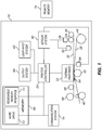
- FIG. 1 shows a system diagram for an exemplary thermal printer 18 in accordance with the present invention.
- thermal printer 18 has a printer controller 20 that causes a thermal printhead 22 to record images onto receiver media 26 by applying heat and pressure to transfer material from a donor ribbon 30 to receiver media 26.
- the receiver media 26 includes a dye receiving layer coated on a substrate.
- the term "receiver media” is used synonymously with the terms “thermal imaging receiver” and “thermal media.”
- the term “donor ribbon” is used synonymously with the terms “thermal donor” and “donor web.”
- Printer controller 20 can include, but is not limited to: a programmable digital computer, a programmable microprocessor, a programmable logic controller, a series of electronic circuits, a series of electronic circuits reduced to the form of an integrated circuit, or a series of discrete components.
- printer controller 20 also controls a receiver drive roller 42, a receiver supply roll 44, a donor ribbon take-up roll 48, and a donor ribbon supply roll 50; which are each motorized for rotation on command of the printer controller 20 to effect movement of receiver media 26 and donor ribbon 30.
- FIG. 2 shows a bottom view of one embodiment of a typical thermal printhead 22 with an array of thermal resistors 43 fabricated in a ceramic substrate 45.
- a heat sink 47 typically in the form of an aluminum backing plate, is fixed to a side of the ceramic substrate 45. Heat sink 47 rapidly dissipates heat generated by the thermal resistors 43 during printing.
- the thermal resistors 43 are arranged in a linear array extending across the width of platen roller 46 (shown in phantom). Such a linear arrangement of thermal resistors 43 is commonly known as a heat line or print line.
- other non-linear arrangements of thermal resistors 43 can be used in various embodiments. Further, it will be appreciated that there are a wide variety of other arrangements of thermal resistors 43 and thermal printheads 22 that can be used in conjunction with the present invention.
- the thermal resistors 43 are adapted to generate heat in proportion to an amount of electrical energy that passes through thermal resistors 43.
- printer controller 20 transmits signals to a circuit board (not shown) to which thermal resistors 43 are connected, causing different amounts of electrical energy to be applied to thermal resistors 43 so as to selectively heat donor ribbon 30 in a manner that is intended to cause donor material to be applied to receiver media 26 in a desired manner.
- donor ribbon 30 comprises a first donor patch set 32.1 having a yellow donor patch 34.1, a magenta donor patch 36.1, a cyan donor patch 38.1 and a clear donor patch 40.1; and a second donor patch set 32.2 having a yellow donor patch 34.2, a magenta donor patch 36.2, a cyan donor patch 38.2 and a clear donor patch 40.2.
- Each donor patch set 32.1 and 32.2 has a patch set leading edge L and a patch set trailing edge T.
- the four patches of a donor patch set are printed, in registration with each other, onto a common image receiving area 52 of receiver media 26 shown in FIG. 3B .
- the printer controller 20 ( FIG. 1 ) provides variable electrical signals in accordance with input image data to the thermal resistors 43 ( FIG. 2 ) in the thermal printhead 22 in order to print an image onto the receiver media 26.
- Each color is successively printed as the receiver media 26 and the donor ribbon move from right to left as seen by the viewer in FIG. 3B .
- leading edge L for first donor patch set 32.1 is the leading edge of yellow donor patch 34.1.
- the position of this leading edge L can be determined by using a position sensor to detect an appropriate marking indicia on donor ribbon 30 that has a known position relative to the leading edge of yellow donor patch 34.1 or by directly detecting the leading edge of yellow donor patch 34.1.
- Printer controller 20 also actuates receiver drive roller 42 ( FIG. 1 ) and receiver supply roll 44 ( FIG. 1 ) so that image receiving area 52 of receiver media 26 is positioned with respect to the thermal printhead 22.
- image receiving area 52 is defined by a receiving area leading edge LER and a receiving area trailing edge TER on receiver media 26.
- Donor ribbon 30 and receiver media 26 are positioned so that donor patch leading edge LED of yellow donor patch 34.1 is registered at thermal printhead 22 with receiving area leading edge LER of image receiving area 52.
- Printer controller 20 then causes a motor or other conventional structure (not shown) to lower thermal printhead 22 so that a lower surface of donor ribbon 30 engages receiver media 26 which is supported by platen roller 46. This creates a pressure holding donor ribbon 30 against receiver media 26.
- Printer controller 20 then actuates receiver drive roller 42 ( FIG. 1 ), receiver supply roll 44 ( FIG. 1 ), donor ribbon take-up roll 48 ( FIG. 1 ), and donor ribbon supply roll 50 ( FIG. 1 ) to move receiver media 26 and donor ribbon 30 together past the thermal printhead 22. Concurrently, printer controller 20 selectively operates thermal resistors 43 ( FIG. 2 ) in thermal printhead 22 to transfer donor material from yellow donor patch 34.1 to receiver media 26.
- a peel member 54 ( FIG. 1 ) separates donor ribbon 30 from receiver media 26.
- Donor ribbon 30 continues over idler roller 56 ( FIG. 1 ) toward the donor ribbon take-up roll 48. As shown in FIG. 3C , printing continues until the receiving area trailing edge TER of image receiving area 52 of receiver media 26 reaches the printing zone between the thermal printhead 22 and the platen roller 46.
- the printer controller 20 then adjusts the position of donor ribbon 30 and receiver media 26 using a predefined pattern of movements so that a leading edge of each of the next donor patches (i.e., magenta donor patch 36.1) in the first donor patch set 32.1 are brought into alignment with receiving area leading edge LER of image receiving area 52 and the printing process is repeated to transfer further material to the image receiving area 52. This process is repeated for each donor patch thereby forming the complete image.
- a leading edge of each of the next donor patches i.e., magenta donor patch 36.1
- magenta donor patch 36.1 in the first donor patch set 32.1 are brought into alignment with receiving area leading edge LER of image receiving area 52 and the printing process is repeated to transfer further material to the image receiving area 52. This process is repeated for each donor patch thereby forming the complete image.
- the printer controller 20 operates the thermal printer 18 based upon input signals from a user input system 62, an output system 64, a memory 68, a communication system 74, and sensor system 80.
- the user input system 62 can comprise any form of transducer or other device capable of receiving an input from a user and converting this input into a form that can be used by printer controller 20.
- user input system 62 can comprise a touch screen input, a touch pad input, a 4-way switch, a 6-way switch, an 8-way switch, a stylus system, a trackball system, a joystick system, a voice recognition system, a gesture recognition system or other such user input systems.
- An output system 64 such as a display or a speaker, is optionally provided and can be used by printer controller 20 to provide human perceptible signals (e.g., visual or audio signals) for feedback, informational or other purposes.
- Memory 68 can take many forms and can include without limitation conventional memory devices including solid state, magnetic, optical or other data storage devices.
- memory 68 is shown having a removable memory interface 71 for communicating with removable memory (not shown) such as a magnetic, optical or magnetic disks.
- the memory 68 is also shown having a hard drive 72 that is fixed with thermal printer 18 and a remote memory 76 that is external to printer controller 20 such as a personal computer, computer network or other imaging system.
- printer controller 20 interfaces with a communication system 74 for communicating external devices such as remote memory 76.
- the communication system 74 can include for example, a wired or wireless network interface that can be used to receive digital image data and other information and instructions from a host computer or network (not shown).
- a sensor system 80 includes circuits and systems that are adapted to detect conditions within thermal printer 18 and, optionally, in the environment surrounding thermal printer 18, and to convert this information into a form that can be used by the printer controller 20 in governing printing operations.
- Sensor system 80 can take a wide variety of forms depending on the type of media therein and the operating environment in which thermal printer 18 is to be used.
- sensor system 80 includes an optional donor position sensor 82 that is adapted to detect the position of donor ribbon 30, and a receiver position sensor 84 that is adapted to detect a position of the receiver media 26.
- the printer controller 20 cooperates with donor position sensor 82 to monitor the donor ribbon 30 during movement thereof so that the printer controller 20 can detect one or more conditions on donor ribbon 30 that indicate a leading edge of a donor patch set.
- the donor ribbon 30 can be provided with markings or other optically, magnetically or electronically sensible indicia between each donor patch set (e.g., donor patch set 32.1) or between donor patches (e.g., donor patches 34.1, 36.1, 38.1, and 40.1).
- donor position sensor 82 is provided to sense these markings or indicia, and to provide signals to controller 20.
- the printer controller 20 can use these markings and indicia to determine when the donor ribbon 30 is positioned with the leading edge of the donor patch set at thermal printhead 22.
- printer controller 20 can use signals from receiver position sensor 84 to monitor the position of the receiver media 26 to align receiver media 26 during printing.
- Receiver position sensor 84 can be adapted to sense markings or other optically, magnetically or electronically sensible indicia between each image receiving area of receiver media 26.
- the printer controller 20 causes donor ribbon 30 to be advanced in a predetermined pattern of distances so as to cause a leading edge of each of the donor patches (e.g., donor patches 34.1, 36.1, 38.1, and 40.1) to be properly positioned relative to the image receiving area 52 at the start each printing process.
- the printer controller 20 can optionally be adapted to achieve such positioning by precise control of the movement of donor ribbon 30 using a stepper type motor for motorizing donor ribbon take-up roll 48 or donor ribbon supply roll 50 or by using a movement sensor 86 that can detect movement of donor ribbon 30.
- a follower wheel 88 is provided that engages donor ribbon 30 and moves therewith.
- Follower wheel 88 can have surface features that are optically, magnetically or electronically sensed by the movement sensor 86.
- the follower wheel 88 that has markings thereon indicative of an extent of movement of donor ribbon 30 and the movement sensor 86 includes a light sensor that can sense light reflected by the markings.
- perforations, cutouts or other routine and detectable indicia can be incorporated onto donor ribbon 30 in a manner that enables the movement sensor 86 to provide an indication of the extent of movement of the donor ribbon 30.
- donor position sensor 82 can be adapted to sense the color of donor patches on donor ribbon 30 and can provide color signals to controller 20.
- the printer controller 20 can be programmed or otherwise adapted to detect a color that is known to be found in the first donor patch in a donor patch set (e.g., yellow donor patch 34.1 in donor patch set 21.1). When the color is detected, the printer controller 20 can determine that the donor ribbon 30 is positioned proximate to the start of the donor patch set.
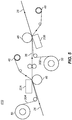
- Donor ribbon supply roll 50 supplies donor ribbon 30.
- Donor ribbon take-up roll 48 receives the used donor ribbon 30.
- a receiver supply roll 44 supplies receiver media 26.
- Receiver media 26 and donor ribbon 30 are merged together between platen roller 46 thermal printhead 22, which includes a heat sink 90 and a peel member 92.
- the peel member 92 separates the donor ribbon 30 from the receiver media 26.
- the donor ribbon 30 continues to travel on to the donor ribbon take-up roll 48, while the receiver media 26 travels between a pinch roller 94 and a micro-grip roller 96 that form a nip.
- the receiver media 26 should have dye receiving layers coated on both sides of a substrate. Various arrangements can then be used to transfer dye onto both sides of the receiver media 26.
- FIG. 5 shows one arrangement that can be used for a duplex thermal printing system 410.
- the main printing components shown in the arrangement of FIG. 4 are duplicated, with one being arranged to print on each side of the receiver media 26.
- a first thermal printhead 22A transfers dye from a first donor ribbon 30A onto a first side of the receiver media 26, and a second thermal printhead 22B transfers dye from a second donor ribbon 30B onto a second side of the receiver media 26.
- This configuration has the advantage that two-sided images can be printed without complex paper handling mechanism.
- the main disadvantage of this approach is that it adds significant cost to the printer since it doubles the number of thermal printheads 22A and 22B and other associated components. It also requires a longer media path, and therefore increases the printer size accordingly.
- Another disadvantage is that two rolls of donor ribbon 30A and 30B must be used, which means that the printer operator will need to stock larger numbers of rolls, and if the donor ribbons 30A and 30B are used at different rates they may need to service the printer more frequently to reload donor ribbon when one of the rolls is used up.
- FIG. 6 shows another arrangement that can be used for a duplex thermal printing system 420.
- the receiver supply roll 44 is provided with a turning mechanism (not shown) that enables it to be pivoted from a first position 422 to a second position 424.
- the printing system configuration is analogous to that shown in FIG. 4 .
- the receiver media 26 is wound back onto the receiver supply roll 44.
- the receiver supply roll 44 is then pivoted into the second position 424 and the receiver media 26 is rethreaded between the thermal printhead 22 and the platen roller 46.
- the opposite side of the receiver media will now be facing the thermal printhead 22 so that the second side of the image can be printed.
- the main disadvantage of this approach is that the turning mechanism for the receiver supply roll 44 adds significant cost to the printer. Since the receiver supply roll 44 is typically quite large relative to the size of the printer, the printer size must also be increased to provide space to position the receiver supply roll 44 into the second position 424.
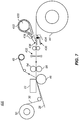
- FIG. 7 shows an embodiment of a duplex thermal printing system 430 that includes a turning mechanism for turning over the receiver media 26.
- a cutter 432 is provided that can be used to cut the receiver media 26 after the first side of the image has been printed.
- a diverter 434 is then repositioned from a first position 435 to a second position 436 in order to feed cut receiver media 433 into the turning mechanism that includes a turn roller 438 and guides 439.
- the cut receiver media 433 is then rethreaded between the thermal printhead 22 and the platen roller 46 where the opposite side of the cut receiver media 433 will now be facing the thermal printhead 22 so that the second side of the image can be printed.
- the turn roller 438 To keep the size of the printer as small as possible, it is desirable for the turn roller 438 to have a relatively small radius. However, if it is made too small it can have the undesirable affect of introducing curl into the cut receiver media 433 and creating scratches and other undesirable markings on the printed surface.
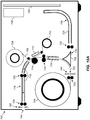
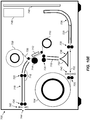
- FIG. 8 shows a diagram illustrating a duplex thermal printer 700 according to a preferred embodiment.
- a receiver media 702 is supplied from a receiver supply roll 704.
- Supply feed rollers 705 are used to feed the receiver media 702 off from the receiver supply roll 704.
- the receiver media 702 is a thermal imaging receiver that has dye receiving layers coated on first and second sides of a substrate in order to enable duplex printing.
- the printing path 716 feeds the receiver media 702 between a thermal printhead 712 and a platen roller 714 in order to print an image by selectively activating thermal resistors 43 ( FIG. 2 ) to transfer dye from a donor ribbon 706 to the receiver media 702.
- the donor ribbon 706 is supplied by a donor ribbon supply roll 708 and the used donor ribbon 706 is wound onto a donor ribbon take-up roll 710.
- the reversing path 726 provides a mechanism to reverse which side of the receiver media 702 that faces the thermal printhead 712.
- the printing path 716 includes printing path guides 718 to guide the path of the receiver media 702, as well as main drive rollers 720, printing path and feed rollers 722.
- the reversing path 726 includes reversing path guides 728 and reversing path feed rollers 730.
- guides and rollers to control the position of receiver media 702 within a printer is well-known in the art and will not be described in further detail here.
- both the printing path 716 and the reversing path 726 include arc-shaped portions 717 and 727, respectively, to provide "J-shaped" paths.
- the use of the arc-shaped portions 717 and 727 enable the printer size to be minimized by keeping the paper paths more compact.
- one or both of the printing path 716 and the reversing path 726 can include a plurality of arc-shaped portions (for example, forming an "S-shaped" path or a "C-shaped” path) to further reduce the printer size, or to control the location where the printed image exits the printer.
- a diverter 732 can be positioned in either a first diverter position 734 or a second diverter position 736.
- the receiver media 702 is directed from the receiver supply roll 704 into the printing path 716. In this position, the receiver media 702 is also directed from the reversing path 726 into the printing path 716.
- the diverter 732 is in the second diverter position 736, the receiver media 702 is directed from the receiver supply roll 704 into the reversing path 726.
- the diverter 732 has a triangular cross-section, where the two top surfaces have a curved profile.
- diverter shapes can alternately be used to appropriately control the path of the receiver media 702.
- a cutter 740 is provided to cut a portion of the receiver media 702 from the receiver supply roll 704.
- a second cutter 742 is provided to trim the ends of the receiver media 702 after an image has been printed.
- the cutters 740 and 742 can use type of media cutting mechanism known in the art.
- the cutters 740 and 742 use a rotary paper cutter mechanism having a wheel-shaped cutting blade which moves along a rail across the width of receiver media 702.
- the cutters 740 and 742 can use other types of media cutting mechanisms, such as guillotine-style cutting blades.
- the printed image can be ejected from the duplex thermal printer 700 through an exit 744 using exit rollers 724.
- exit rollers 724 Commonly an exit tray (not shown) is provided into which the printed image drops as it passes out of the exit 744.
- a printer controller 748 is used to control the operation of the duplex thermal printer 700.
- the printer controller 748 can include, but is not limited to: a programmable digital computer, a programmable microprocessor, a programmable logic controller, a series of electronic circuits, a series of electronic circuits reduced to the form of an integrated circuit, or a series of discrete components.
- the printer controller 748 controls the thermal printhead 712 to record images onto the receiver media 702.
- the printer controller 748 also controls other components such as the various rollers and cutters 740 and 742 shown in FIG. 8 .
- a power supply 746 is used to supply power to the printer controller 748, and to other electrical printer components.
- the duplex thermal printer 700 also includes a variety of other components that are not shown in FIG. 8 , such as the standard components that were described earlier with respect to FIG. 1 .
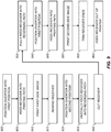
- FIG. 9 shows a flow diagram summarizing the steps involved with operating the components of the duplex thermal printer 700 of FIG. 8 to provide duplex printing according to a preferred embodiment.
- FIGS. 10A-10I show a set of accompanying diagrams illustrating the operation of the duplex thermal printer 700 during the duplex printing process.
- a position diverter into first position step 800 is used to position the diverter 732 into the first diverter position 734.
- a feed receiver into printing path step 805 is then used to feed the receiver media 702 from the receiver supply roll 704 into the printing path 716 by activating appropriate drive rollers as shown in FIG. 10A .
- the receiver media 702 is fed into the printing path 716 to the point where the portion of the receiver media 702 that is to receive the printed image is moved past the thermal printhead 712.
- a print first side image step 810 is then used to print a first side image onto a first side of the receiver media 702. This is accomplished by moving the receiver media 702 past the thermal printhead 712, during which time the thermal printhead 712 applies heat pulses to transfer colorant (e.g., dye) from the donor ribbon 706 onto the first side of the receiver media 702 in accordance with image data for the first side image, thereby printing the first-side image. This is illustrated in FIG. 10B .
- the receiver media 702 is wound back onto the receiver supply roll 704 during the print first side image step 810.
- the receiver media 702 can be moved in the opposite direction during the printing operation.
- the duplex thermal printer 700 is adapted to print color images.
- the donor ribbon 706 typically includes a sequence of donor patches, each having a donor material of a different color as was discussed relative to FIG. 3A .
- the print first side image step 810 will generally involve moving the receiver media 702 past the thermal printhead 712 a plurality of times for a plurality of print passes, each time transferring colorant from a donor patch having a different color. Between each of the print passes, the receiver media 702 is repositioned so that the leading edge of the first side image is aligned with the thermal printhead 712. Likewise, the donor ribbon 706 is positioned so that a leading edge of the appropriate donor patch is properly aligned with respect to the thermal printhead 712.
- a rewind receiver step 815 is used to rewind the receiver media 702 back onto the receiver supply roll 704 as illustrated in FIG. 10C .
- the receiver media 702 is rewound at least to the point where the leading edge of the receiver media 702 is clear of the diverter 732.
- a position diverter into second position step 820 is then used to reposition the diverter 732 into the second diverter position 736 as illustrated in FIG. 10D .
- the receiver media 702 is then partially fed into the reversing path 726 using a partially feed receiver into reversing path step 825 as shown in FIG. 10E .
- the receiver media 702 is advanced to the point where the printed portion of the receiver media 702 is moved past the cutter 740. Since thermal printing systems generally require at least some amount of border be maintained on the leading and trailing edges of the receiver media 702 to adequately hold and control the receiver media 702 during the printing process, the receiver media 702 should be positioned so that the receiver media 702 can be cut with the appropriate border size.
- a cut receiver step 830 is then used to cut the receiver media 702 by activating the cutter 740, thereby severing a cut receiver sheet 750 from the receiver supply roll 704. Generally, the receiver media 702 should be stopped before activating the cutter 740.
- a fully feed receiver into reversing path step 835 is then used to feed the cut receiver sheet 750 fully into the reversing path 726 as shown in FIG. 10F .
- a position diverter into first position step 840 is used to reposition the diverter 732 into the first diverter position 734 as shown in FIG. 10G .
- a feed receiver into printing path step 845 then feeds the cut receiver sheet 750 into the printing path 716.
- the second side of the cut receiver sheet 750 is now oriented to face the thermal printhead 712, thereby enabling a second side image to be printed.
- a print second side image step 850 is then used to print the second side image onto the second side of the cut receiver sheet 750. This is accomplished by moving the cut receiver sheet 750 past the thermal printhead 712, during which time the thermal printhead 712 applies heat pulses to transfer colorant (e.g., dye) from the donor ribbon 706 onto the second side of the cut receiver sheet 750 in accordance with image data for the second side image, thereby printing the second-side image. This is illustrated in FIG. 10H .
- the print second side image step 850 may involve a plurality of print passes to print color images using a plurality of different colorants.
- the cut receiver sheet 750 is moved in a downward direction during the print second side image step 850. In other embodiments the cut receiver sheet 750 can be moved in the opposite direction during the printing operation.
- an optional trim receiver ends step 855 can be used to trim one or more ends off of the cut receiver sheet 750.
- the cut receiver sheet 750 is fed toward the exit 744 until the first end portion to be trimmed off extends beyond the cutter 742 as shown in FIG. 10I .
- the movement of the cut receiver sheet 750 is then paused and the cutter 742 is activated to cut off the first end portion of the cut receiver sheet 750.
- a waste bin (not shown) is provided into which the first end portion will fall when it is cut off. The waste bin can be emptied periodically by an operator.
- the cut receiver sheet 750 is then advanced further until the printed portion of the cut receiver sheet 750 (i.e., the portion of the cut receiver sheet 750 to be kept) extends beyond the cutter 742.
- the movement of the cut receiver sheet 750 is then paused and the cutter 742 is activated to cut off the second end portion of the cut receiver sheet 750.
- the second end portion can then be allowed to fall into the waste bin.
- a feed receiver out of printer step 860 is then used to feed the cut receiver sheet 750 out of the duplex thermal printer 700, where it can be provided to the customer, or can be passed onto other finishing operations (such as a binding operation to form a photo book with including a plurality of printed pages).
- the cut receiver sheet 750 may be extended out of the exit 744 a substantial distance at the time that the trim receiver ends step 855 trims the second end portion of the cut receiver sheet 750. In this case, the cut receiver sheet 750 can simply be allowed to fall into an output tray (not shown). In other cases, the cut receiver sheet 750 may be fed out of the duplex thermal printer 700 using feed rollers.
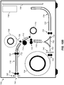
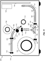
- FIG. 11 shows an alternate embodiment of a duplex thermal printer 900, which is identical to the duplex thermal printer 700 of FIG. 8 except that the cutters 740 and 742 have been replaced with a single cutter 902.
- duplex thermal printer 900 The operation of the duplex thermal printer 900 is analogous to that which was described relative to the flow diagram of FIG. 9 for the duplex thermal printer 700. The main differences relate to the positioning of the receiver media 702 for the cutting operations.
- the receiver media 702 needs to be fed further into the reversing path 726 before it is cut. After the cut receiver sheet 750 has been cut off, the remaining uncut portion of the receiver media 702 should then be wound back onto the receiver supply roll 707 until it clears the diverter 732 before it can be moved back into the first diverter position 734.
- the cutter 902 is also used to perform the trim receiver ends step 855.
- the cut receiver sheet 750 is directed back into the reversing path 726 until the first end portion to be trimmed off extends beyond the cutter 902, at which point the cutter 902 is activated to cut off the first end portion of the cut receiver sheet 750.
- the cut receiver sheet 750 is then advanced further until the printed portion of the cut receiver sheet 750 (i.e., the portion of the cut receiver sheet 750 to be kept) extends beyond the cutter 902, at which point the cutter 902 is activated again to cut off the second end portion of the cut receiver sheet 750.
- the cut receiver sheet 750 can then be fed back through the printing path 716 and out the exit 744.
- the configuration of the duplex thermal printer 900 of FIG. 11 provides a cost advantage relative to the duplex thermal printer 700 of FIG. 8 due to the need for one less cutter mechanism. However, it will generally be slightly disadvantaged for print speed due to the extra distance that the cut receiver sheet 750 must travel during the process of trimming the ends.
- the exit 744 can be repositioned to the end of the reversing path 726 to minimize the distance that the cut receiver sheet must travel after the trimming process is completed.
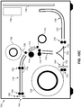
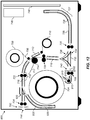
- FIG. 13 shows an embodiment of a duplex thermal printer 905 that includes several optional features.
- One problem that can occur with roll-fed receiver media is curl that is introduced by the media being stored on the receiver supply roll 704.
- the receiver supply roll 704 can be turned so that the receiver media 702 feeds off the receiver supply roll 704 when it is turned in a clockwise direction.
- the receiver media 702 can then be pulled around a receiver decurling roller 910 in an orientation that counteracts the curl that was introduced by the receiver media 702 being wound around the receiver supply roll 704, thereby relieving some or all of the curl.
- Guides 915 can be used to guide the receiver media 702 around the receiver decurling roller 910 and into the supply feed rollers 705.
- an upper diverter 920 can be used to divert the receiver media 702 into an internal path 925 with internal path guides 930.
- the upper diverter 920 is positioned in a first raised position during the printing passes to direct the receiver media 702 into the internal path 925.
- the upper diverter 920 can be repositioned to a second lowered position, direction the receiver media 702 toward the exit 744. In this way, the receiver media 744 never leaves the duplex thermal printer 905 until the printing process is complete.
Claims (13)
- Walzengeführtes Duplex-Thermodrucksystem (700), das aufweist:eine Versorgungswalze (704) eines Thermoabbildungsempfängers mit farbaufnehmenden Schichten auf ersten und zweiten Seiten eines Substrats;einen Druckweg (716);einen Rückwärtsweg (726);ein Umlenkstück (732) mit einer ersten Position (734) und einer zweiten Position (736), wobeiwenn das Umlenkstück in der ersten Position ist, der Thermoabbildungsempfänger von der Versorgungswalze in den Druckweg geleitet wird und der Thermoabbildungsempfänger von dem Rückwärtsweg in den Druckweg geleitet wird, und wenn das Umlenkstück in der zweiten Position ist, der Thermoabbildungsempfänger von der Versorgungswalze in den Rückwärtsweg geleitet wird,einen Thermodruckkopf (712), der entlang des Druckwegs positioniert ist;ein Spenderband (706), das von einer Spenderversorgungswalze (708) an dem Thermodruckkopf vorbei zu einer Spenderaufnahmewalze (710) transportiert wird,wobei das Spenderband ein oder mehrere Spenderflecken hat, von denen jeder ein jeweiliges Spendermaterial hat;eine Schneideinrichtung (740), die zwischen der Versorgungswalze und dem Rückweg positioniert ist; undeine Druckersteuerung (20), die Komponenten des Thermodrucksystems steuert, um die folgende Abfolge von Arbeitsgängen durchzuführen:Positionieren des Umlenkstücks in der ersten Position;Transportieren des Thermoabbildungsempfängers von der Versorgungswalze in den Druckweg, so dass die erste Seite des Thermoabbildungsempfängers derart orientiert ist, dass sie dem Thermodruckkopf zugewandt ist;Bewegen des Thermoabbildungsempfängers und des Spenderbands an dem Thermodruckkopf vorbei, wobei der Thermodruckkopf während dieser Zeit Wärmeimpulse anwendet, um Farbstoff von dem Spenderband auf die erste Seite des Thermoabbildungsempfängers zu übertragen, wodurch ein Bild auf die erste Seite gedruckt wird;Wickeln des Thermoabbildungsempfängers zurück auf die Versorgungswalze;Positionieren des Ablenkstücks in der zweiten Position;teilweises Transportieren des Thermoabbildungsempfängers von der Versorgungswalze in den Rückwärtsweg;Verwenden der Schneideinrichtung, um einen Abschnitt des Thermoabbildungsempfängers mit dem Bild auf der ersten Seite von der Versorgungswalze abzuschneiden;vollständiges Transportieren des geschnittenen Thermoabbildungsempfängers in den Rückwärtsweg;Positionieren des Umlenkstücks in der ersten Position;Transportieren des geschnittenen Thermoabbildungsempfängers in den Druckweg, so dass die zweite Seite des Thermoabbildungsempfängers derart orientiert ist, dass sie dem Thermodruckkopf zugewandt ist;Bewegen des geschnittenen Thermoabbildungsempfängers und des Spenderbands an dem Thermodruckkopf vorbei, wobei während dieser Zeit der Thermodruckkopf Wärmeimpulse anwendet, um Farbstoff von einem Spenderband auf die zweite Seite des Thermoabbildungsempfängers zu übertragen, wodurch ein Bild auf eine zweite Seite gedruckt wird; undTransportieren des geschnittenen Thermoabbildungsempfängers aus dem Drucksystem.
- Walzengeführtes Duplex-Thermodrucksystem nach Anspruch 1, wobei der Druckweg und/oder der Rückwärtsweg einen bogenförmigen Abschnitt umfassen/umfasst.
- Walzengeführtes Duplex-Thermodrucksystem nach Anspruch 1, wobei das Drucksystem ein Farbdrucksystem ist, und wobei der Thermoabbildungsempfänger mehrere Male an dem Thermodruckkopf vorbei bewegt wird, während das Bild auf der ersten Seite und/oder das Bild auf der zweiten Seite gedruckt werden/wird, um mehrere Spendermaterialien von entsprechenden mehreren Spenderflecken, die nacheinander auf dem Spenderband positioniert sind, zu übertragen, wobei die Spendermaterialien entsprechende mehrere verschiedene Farbstoffe umfassen.
- Walzengeführtes Duplex-Thermodrucksystem nach Anspruch 3, wobei die Spenderflecken einen durchsichtigen Spenderflecken zum Anwenden eines Spendermaterials, das eine Schutzbeschichtung über den gedruckten Farbstoffen bereitstellt, umfassen.
- Walzengeführtes Duplex-Thermodrucksystem nach Anspruch 1, wobei die Schneideinrichtung zwischen der Versorgungswalze und dem Umlenkstück positioniert ist.
- Walzengeführtes Duplex-Thermodrucksystem nach Anspruch 1, das ferner eine zweite Schneideinrichtung umfasst, die entlang des Druckwegs positioniert ist, wobei die zweite Schneideinrichtung verwendet wird, um mindestens ein Ende des geschnittenen Thermoabbildungsempfängers zurechtzuschneiden, nachdem das Bild auf die zweite Seite gedruckt wurde.
- Walzengeführtes Duplex-Thermodrucksystem nach Anspruch 1, wobei das Umlenkstück einen dreieckigen Querschnitt mit drei Rändern hat.
- Walzengeführtes Duplex-Thermodrucksystem nach Anspruch 7, wobei ein oder mehrere der Ränder ein gekrümmtes Profil haben.
- Walzengeführtes Duplex-Thermodrucksystem nach Anspruch 1, wobei der Druckweg Führungen zum Führen der Empfängermedien durch den Druckweg und Transportwalzen zum Transportieren der Empfängermedien durch den Druckweg umfasst.
- Walzengeführtes Duplex-Thermodrucksystem nach Anspruch 1, wobei der Rückwärtsweg Führungen zum Führen der Empfängermedien durch den Rückwärtsweg und Transportrollen zum Transportieren der Empfängermedien durch den Rückwärtsweg umfasst.
- Walzengeführtes Duplex-Thermodrucksystem nach Anspruch 1, wobei der geschnittene Thermoabbildungsempfänger durch einen Ausgang am Ende des Druckwegs oder durch einen Ausgang am Ende des Rückwärtswegs aus dem Drucksystem transportiert wird.
- Walzengeführtes Duplex-Thermodrucksystem nach Anspruch 1, das ferner eine Glättwalze umfasst, wobei der Thermoabbildungsempfänger in einer Orientierung um die Empfängerglättwalze gezogen wird, die einer Welle des Thermoabbildungsempfängers, die dadurch eingeschleppt wird, dass der Thermoabbildungsempfänger um die Versorgungswalze gewickelt ist, entgegen wirkt.
- Walzengeführtes Duplex-Thermodrucksystem nach Anspruch 1, das ferner ein zweites Umlenkstück umfasst, das zwischen dem Thermodruckkopf und einem Ausgang am Ende des Druckwegs positioniert ist, wobei das zweite Umlenkstück eine erste Position und eine zweite Position hat, wobei, wenn das zweite Umlenkstück in der ersten Position ist, der Thermoabbildungsempfänger von dem Druckweg in einen internen Medienweg geleitet wird, und wenn das zweite Umlenkstück in der zweiten Position ist, der Thermoabbildungsempfänger durch den Ausgang am Ende des Druckwegs aus dem Drucksystem geleitet wird.
Applications Claiming Priority (2)
| Application Number | Priority Date | Filing Date | Title |
|---|---|---|---|
| US13/532,865 US8599229B1 (en) | 2012-06-26 | 2012-06-26 | Roll-fed duplex thermal printing system |
| PCT/US2013/045767 WO2014004105A1 (en) | 2012-06-26 | 2013-06-14 | Roll-fed duplex thermal printing system |
Publications (2)
| Publication Number | Publication Date |
|---|---|
| EP2864125A1 EP2864125A1 (de) | 2015-04-29 |
| EP2864125B1 true EP2864125B1 (de) | 2017-05-17 |
Family
ID=48703912
Family Applications (1)
| Application Number | Title | Priority Date | Filing Date |
|---|---|---|---|
| EP13732770.6A Active EP2864125B1 (de) | 2012-06-26 | 2013-06-14 | Walzengeführtes duplex-thermodrucksystem |
Country Status (8)
| Country | Link |
|---|---|
| US (2) | US8599229B1 (de) |
| EP (1) | EP2864125B1 (de) |
| JP (1) | JP2015528757A (de) |
| KR (1) | KR20150034189A (de) |
| CN (1) | CN104395090A (de) |
| BR (1) | BR112014032499A2 (de) |
| IN (1) | IN2014DN09964A (de) |
| WO (1) | WO2014004105A1 (de) |
Families Citing this family (11)
| Publication number | Priority date | Publication date | Assignee | Title |
|---|---|---|---|---|
| US8885003B2 (en) * | 2012-06-26 | 2014-11-11 | Kodak Alaris Inc. | Duplex thermal printing system with pivotable diverter |
| US8599229B1 (en) * | 2012-06-26 | 2013-12-03 | Kodak Alaris Inc. | Roll-fed duplex thermal printing system |
| JP6320052B2 (ja) * | 2014-01-20 | 2018-05-09 | 三菱電機株式会社 | サーマルプリンタ |
| TWI508870B (zh) * | 2014-05-26 | 2015-11-21 | Hiti Digital Inc | 具有雙面列印功能之列印裝置 |
| CN105751710A (zh) * | 2016-02-23 | 2016-07-13 | 昇捷丰电子(厦门)有限公司 | 具有手势扫描识别功能的手持喷码机及实现该功能的方法 |
| CN105799328B (zh) * | 2016-03-28 | 2017-11-03 | 昇捷丰电子(厦门)有限公司 | 一种内置读码器的热发泡喷墨手持喷码机 |
| JP6643163B2 (ja) * | 2016-03-30 | 2020-02-12 | シチズン時計株式会社 | プリンタ |
| JP6632451B2 (ja) * | 2016-03-30 | 2020-01-22 | シチズン時計株式会社 | プリンタ |
| JP7368930B2 (ja) * | 2017-08-30 | 2023-10-25 | 株式会社ミマキエンジニアリング | 多層印刷物製造システムおよび多層印刷物製造装置 |
| CN109130471B (zh) * | 2018-04-24 | 2020-11-13 | 杭州护章神网络有限公司 | 数据化的盖印机及盖印方法 |
| JP2021123447A (ja) * | 2020-02-04 | 2021-08-30 | キヤノン株式会社 | シート給送装置及び記録装置 |
Family Cites Families (22)
| Publication number | Priority date | Publication date | Assignee | Title |
|---|---|---|---|---|
| US5284816A (en) * | 1992-11-19 | 1994-02-08 | Eastman Kodak Company | Two-sided thermal printing system |
| KR970058945A (ko) * | 1996-01-17 | 1997-08-12 | 김광호 | 열전사 프린터 |
| JPH09327950A (ja) * | 1996-06-11 | 1997-12-22 | Sony Corp | 両面印刷装置 |
| JP2001310503A (ja) * | 2000-04-28 | 2001-11-06 | Canon Inc | 記録装置 |
| US6705786B2 (en) * | 2002-04-11 | 2004-03-16 | Hewlett-Packard Development Company, L.P. | Duplex printing of print sheets |
| US6715949B1 (en) | 2002-09-20 | 2004-04-06 | Eastman Kodak Company | Medium-handling in printer for donor and receiver mediums |
| KR100636135B1 (ko) * | 2003-12-31 | 2006-10-19 | 삼성전자주식회사 | 양면인쇄장치의 화상정렬 인쇄방법 |
| US7762786B2 (en) * | 2004-01-30 | 2010-07-27 | Hubbell Incorporated | Integrated fire pump controller and automatic transfer switch |
| KR100544207B1 (ko) * | 2004-07-30 | 2006-01-23 | 삼성전자주식회사 | 인쇄장치의 얼라인먼트 조정방법 및 장치 |
| US7295223B2 (en) * | 2004-07-30 | 2007-11-13 | Samsung Electronics Co., Ltd. | Method and apparatus for adjusting an image alignment for an image forming apparatus |
| JP4421984B2 (ja) * | 2004-09-17 | 2010-02-24 | セイコーインスツル株式会社 | シート状記録物の一時保留機構および、これを備えたプリンタ |
| US7675534B2 (en) * | 2006-12-22 | 2010-03-09 | Eastman Kodak Company | Printer with short print-to-print cycle times |
| TWM328379U (en) * | 2007-09-05 | 2008-03-11 | Lite On Technology Corp | Sheet feeding mechanism with duplex print function and printer thereof |
| JP2009066815A (ja) * | 2007-09-11 | 2009-04-02 | Fuji Xerox Co Ltd | 印刷装置及び印刷システム |
| US8029202B2 (en) | 2008-03-14 | 2011-10-04 | Citizen Holdings Co., Ltd. | Printer with recording paper leading edge storage unit |
| JP2011143628A (ja) * | 2010-01-15 | 2011-07-28 | Seiko Epson Corp | 記録紙の印刷方法および両面印刷装置 |
| US8757909B2 (en) * | 2010-06-18 | 2014-06-24 | Canon Kabushiki Kaisha | Image forming apparatus with cutting unit |
| US8749604B2 (en) * | 2012-03-16 | 2014-06-10 | Kodak Alaris Inc. | Printing system for reducing printer artifacts |
| US8743163B2 (en) * | 2012-03-16 | 2014-06-03 | Kodak Alaris Inc. | Printing method for reducing printer artifacts |
| US8599230B1 (en) * | 2012-06-26 | 2013-12-03 | Kodak Alaris Inc. | Roll-fed duplex thermal printer |
| US8885003B2 (en) * | 2012-06-26 | 2014-11-11 | Kodak Alaris Inc. | Duplex thermal printing system with pivotable diverter |
| US8599229B1 (en) * | 2012-06-26 | 2013-12-03 | Kodak Alaris Inc. | Roll-fed duplex thermal printing system |
-
2012
- 2012-06-26 US US13/532,865 patent/US8599229B1/en active Active
-
2013
- 2013-06-14 EP EP13732770.6A patent/EP2864125B1/de active Active
- 2013-06-14 IN IN9964DEN2014 patent/IN2014DN09964A/en unknown
- 2013-06-14 KR KR20157001631A patent/KR20150034189A/ko not_active Application Discontinuation
- 2013-06-14 WO PCT/US2013/045767 patent/WO2014004105A1/en active Application Filing
- 2013-06-14 CN CN201380033341.2A patent/CN104395090A/zh active Pending
- 2013-06-14 BR BR112014032499A patent/BR112014032499A2/pt not_active Application Discontinuation
- 2013-06-14 JP JP2015520262A patent/JP2015528757A/ja active Pending
- 2013-11-02 US US14/070,497 patent/US8907995B2/en active Active
Also Published As
| Publication number | Publication date |
|---|---|
| US8907995B2 (en) | 2014-12-09 |
| WO2014004105A1 (en) | 2014-01-03 |
| IN2014DN09964A (de) | 2015-08-14 |
| US8599229B1 (en) | 2013-12-03 |
| US20140055549A1 (en) | 2014-02-27 |
| KR20150034189A (ko) | 2015-04-02 |
| JP2015528757A (ja) | 2015-10-01 |
| CN104395090A (zh) | 2015-03-04 |
| US20130342626A1 (en) | 2013-12-26 |
| EP2864125A1 (de) | 2015-04-29 |
| BR112014032499A2 (pt) | 2017-06-27 |
Similar Documents
| Publication | Publication Date | Title |
|---|---|---|
| EP3036109B1 (de) | Duplex-thermodrucksystem mit schwenkbarer weiche | |
| EP2864125B1 (de) | Walzengeführtes duplex-thermodrucksystem | |
| US8599230B1 (en) | Roll-fed duplex thermal printer | |
| JP4525212B2 (ja) | 熱転写プリンタ | |
| EP1955857B1 (de) | Drucker und Druckverfahren | |
| JP2007196454A (ja) | サーマルプリンタ及びサーマルプリンタの印画方法 | |
| US7507046B2 (en) | Borderless platen drive printing | |
| JP2007038464A (ja) | 印刷装置、リボン搬送制御装置、リボンフィルム、リボン搬送制御方法及びプログラム | |
| JP4940673B2 (ja) | プリンタ、およびプリント制御方法 | |
| US8585034B1 (en) | Receiver supply using cut sheet media | |
| US8820915B2 (en) | Method for handling cut sheet media | |
| US9434569B2 (en) | Offset print stacking tray with waste area | |
| JP2007038442A (ja) | インクリボン、およびプリンタ | |
| JP2011046157A (ja) | サーマルプリンタ | |
| JP2017007298A (ja) | プリンタ、インクリボン | |
| JP5901274B2 (ja) | 印刷装置およびその制御方法 | |
| JP2005132027A (ja) | 印刷物、印刷装置及び印刷方法 | |
| JP2007076054A (ja) | 通帳類作成装置 | |
| JP2008302522A (ja) | 画像形成装置 | |
| JP2005225168A (ja) | 印刷装置及び印刷方法 | |
| JP2004314569A (ja) | プリンタ | |
| JP2006175751A (ja) | 印刷装置 | |
| JP2013112507A (ja) | 印刷装置、その制御方法およびプログラム | |
| JP2005078355A (ja) | 通帳類印刷装置及び通帳類印刷方法 |
Legal Events
| Date | Code | Title | Description |
|---|---|---|---|
| PUAI | Public reference made under article 153(3) epc to a published international application that has entered the european phase |
Free format text: ORIGINAL CODE: 0009012 |
|
| 17P | Request for examination filed |
Effective date: 20141227 |
|
| AK | Designated contracting states |
Kind code of ref document: A1 Designated state(s): AL AT BE BG CH CY CZ DE DK EE ES FI FR GB GR HR HU IE IS IT LI LT LU LV MC MK MT NL NO PL PT RO RS SE SI SK SM TR |
|
| AX | Request for extension of the european patent |
Extension state: BA ME |
|
| DAX | Request for extension of the european patent (deleted) | ||
| GRAP | Despatch of communication of intention to grant a patent |
Free format text: ORIGINAL CODE: EPIDOSNIGR1 |
|
| RIC1 | Information provided on ipc code assigned before grant |
Ipc: B41J 3/60 20060101AFI20161110BHEP Ipc: B41J 15/04 20060101ALI20161110BHEP Ipc: B41J 13/00 20060101ALI20161110BHEP Ipc: B41J 11/66 20060101ALI20161110BHEP |
|
| INTG | Intention to grant announced |
Effective date: 20161125 |
|
| GRAS | Grant fee paid |
Free format text: ORIGINAL CODE: EPIDOSNIGR3 |
|
| GRAA | (expected) grant |
Free format text: ORIGINAL CODE: 0009210 |
|
| AK | Designated contracting states |
Kind code of ref document: B1 Designated state(s): AL AT BE BG CH CY CZ DE DK EE ES FI FR GB GR HR HU IE IS IT LI LT LU LV MC MK MT NL NO PL PT RO RS SE SI SK SM TR |
|
| REG | Reference to a national code |
Ref country code: GB Ref legal event code: FG4D |
|
| REG | Reference to a national code |
Ref country code: CH Ref legal event code: EP |
|
| REG | Reference to a national code |
Ref country code: FR Ref legal event code: PLFP Year of fee payment: 5 |
|
| REG | Reference to a national code |
Ref country code: IE Ref legal event code: FG4D |
|
| REG | Reference to a national code |
Ref country code: AT Ref legal event code: REF Ref document number: 894099 Country of ref document: AT Kind code of ref document: T Effective date: 20170615 |
|
| REG | Reference to a national code |
Ref country code: DE Ref legal event code: R096 Ref document number: 602013021257 Country of ref document: DE |
|
| REG | Reference to a national code |
Ref country code: NL Ref legal event code: FP |
|
| REG | Reference to a national code |
Ref country code: LT Ref legal event code: MG4D |
|
| REG | Reference to a national code |
Ref country code: AT Ref legal event code: MK05 Ref document number: 894099 Country of ref document: AT Kind code of ref document: T Effective date: 20170517 |
|
| PG25 | Lapsed in a contracting state [announced via postgrant information from national office to epo] |
Ref country code: GR Free format text: LAPSE BECAUSE OF FAILURE TO SUBMIT A TRANSLATION OF THE DESCRIPTION OR TO PAY THE FEE WITHIN THE PRESCRIBED TIME-LIMIT Effective date: 20170818 Ref country code: FI Free format text: LAPSE BECAUSE OF FAILURE TO SUBMIT A TRANSLATION OF THE DESCRIPTION OR TO PAY THE FEE WITHIN THE PRESCRIBED TIME-LIMIT Effective date: 20170517 Ref country code: HR Free format text: LAPSE BECAUSE OF FAILURE TO SUBMIT A TRANSLATION OF THE DESCRIPTION OR TO PAY THE FEE WITHIN THE PRESCRIBED TIME-LIMIT Effective date: 20170517 Ref country code: ES Free format text: LAPSE BECAUSE OF FAILURE TO SUBMIT A TRANSLATION OF THE DESCRIPTION OR TO PAY THE FEE WITHIN THE PRESCRIBED TIME-LIMIT Effective date: 20170517 Ref country code: LT Free format text: LAPSE BECAUSE OF FAILURE TO SUBMIT A TRANSLATION OF THE DESCRIPTION OR TO PAY THE FEE WITHIN THE PRESCRIBED TIME-LIMIT Effective date: 20170517 Ref country code: AT Free format text: LAPSE BECAUSE OF FAILURE TO SUBMIT A TRANSLATION OF THE DESCRIPTION OR TO PAY THE FEE WITHIN THE PRESCRIBED TIME-LIMIT Effective date: 20170517 Ref country code: NO Free format text: LAPSE BECAUSE OF FAILURE TO SUBMIT A TRANSLATION OF THE DESCRIPTION OR TO PAY THE FEE WITHIN THE PRESCRIBED TIME-LIMIT Effective date: 20170817 |
|
| PG25 | Lapsed in a contracting state [announced via postgrant information from national office to epo] |
Ref country code: LV Free format text: LAPSE BECAUSE OF FAILURE TO SUBMIT A TRANSLATION OF THE DESCRIPTION OR TO PAY THE FEE WITHIN THE PRESCRIBED TIME-LIMIT Effective date: 20170517 Ref country code: IS Free format text: LAPSE BECAUSE OF FAILURE TO SUBMIT A TRANSLATION OF THE DESCRIPTION OR TO PAY THE FEE WITHIN THE PRESCRIBED TIME-LIMIT Effective date: 20170917 Ref country code: PL Free format text: LAPSE BECAUSE OF FAILURE TO SUBMIT A TRANSLATION OF THE DESCRIPTION OR TO PAY THE FEE WITHIN THE PRESCRIBED TIME-LIMIT Effective date: 20170517 Ref country code: RS Free format text: LAPSE BECAUSE OF FAILURE TO SUBMIT A TRANSLATION OF THE DESCRIPTION OR TO PAY THE FEE WITHIN THE PRESCRIBED TIME-LIMIT Effective date: 20170517 Ref country code: SE Free format text: LAPSE BECAUSE OF FAILURE TO SUBMIT A TRANSLATION OF THE DESCRIPTION OR TO PAY THE FEE WITHIN THE PRESCRIBED TIME-LIMIT Effective date: 20170517 Ref country code: BG Free format text: LAPSE BECAUSE OF FAILURE TO SUBMIT A TRANSLATION OF THE DESCRIPTION OR TO PAY THE FEE WITHIN THE PRESCRIBED TIME-LIMIT Effective date: 20170817 |
|
| PG25 | Lapsed in a contracting state [announced via postgrant information from national office to epo] |
Ref country code: EE Free format text: LAPSE BECAUSE OF FAILURE TO SUBMIT A TRANSLATION OF THE DESCRIPTION OR TO PAY THE FEE WITHIN THE PRESCRIBED TIME-LIMIT Effective date: 20170517 Ref country code: RO Free format text: LAPSE BECAUSE OF FAILURE TO SUBMIT A TRANSLATION OF THE DESCRIPTION OR TO PAY THE FEE WITHIN THE PRESCRIBED TIME-LIMIT Effective date: 20170517 Ref country code: DK Free format text: LAPSE BECAUSE OF FAILURE TO SUBMIT A TRANSLATION OF THE DESCRIPTION OR TO PAY THE FEE WITHIN THE PRESCRIBED TIME-LIMIT Effective date: 20170517 Ref country code: CZ Free format text: LAPSE BECAUSE OF FAILURE TO SUBMIT A TRANSLATION OF THE DESCRIPTION OR TO PAY THE FEE WITHIN THE PRESCRIBED TIME-LIMIT Effective date: 20170517 Ref country code: SK Free format text: LAPSE BECAUSE OF FAILURE TO SUBMIT A TRANSLATION OF THE DESCRIPTION OR TO PAY THE FEE WITHIN THE PRESCRIBED TIME-LIMIT Effective date: 20170517 |
|
| REG | Reference to a national code |
Ref country code: CH Ref legal event code: PL |
|
| REG | Reference to a national code |
Ref country code: DE Ref legal event code: R097 Ref document number: 602013021257 Country of ref document: DE |
|
| PG25 | Lapsed in a contracting state [announced via postgrant information from national office to epo] |
Ref country code: SM Free format text: LAPSE BECAUSE OF FAILURE TO SUBMIT A TRANSLATION OF THE DESCRIPTION OR TO PAY THE FEE WITHIN THE PRESCRIBED TIME-LIMIT Effective date: 20170517 Ref country code: IT Free format text: LAPSE BECAUSE OF FAILURE TO SUBMIT A TRANSLATION OF THE DESCRIPTION OR TO PAY THE FEE WITHIN THE PRESCRIBED TIME-LIMIT Effective date: 20170517 |
|
| REG | Reference to a national code |
Ref country code: IE Ref legal event code: MM4A |
|
| PLBE | No opposition filed within time limit |
Free format text: ORIGINAL CODE: 0009261 |
|
| STAA | Information on the status of an ep patent application or granted ep patent |
Free format text: STATUS: NO OPPOSITION FILED WITHIN TIME LIMIT |
|
| 26N | No opposition filed |
Effective date: 20180220 |
|
| PG25 | Lapsed in a contracting state [announced via postgrant information from national office to epo] |
Ref country code: LU Free format text: LAPSE BECAUSE OF NON-PAYMENT OF DUE FEES Effective date: 20170614 Ref country code: CH Free format text: LAPSE BECAUSE OF NON-PAYMENT OF DUE FEES Effective date: 20170630 Ref country code: LI Free format text: LAPSE BECAUSE OF NON-PAYMENT OF DUE FEES Effective date: 20170630 Ref country code: IE Free format text: LAPSE BECAUSE OF NON-PAYMENT OF DUE FEES Effective date: 20170614 |
|
| REG | Reference to a national code |
Ref country code: FR Ref legal event code: PLFP Year of fee payment: 6 |
|
| PG25 | Lapsed in a contracting state [announced via postgrant information from national office to epo] |
Ref country code: SI Free format text: LAPSE BECAUSE OF FAILURE TO SUBMIT A TRANSLATION OF THE DESCRIPTION OR TO PAY THE FEE WITHIN THE PRESCRIBED TIME-LIMIT Effective date: 20170517 |
|
| REG | Reference to a national code |
Ref country code: BE Ref legal event code: MM Effective date: 20170630 |
|
| PG25 | Lapsed in a contracting state [announced via postgrant information from national office to epo] |
Ref country code: BE Free format text: LAPSE BECAUSE OF NON-PAYMENT OF DUE FEES Effective date: 20170630 |
|
| PG25 | Lapsed in a contracting state [announced via postgrant information from national office to epo] |
Ref country code: MT Free format text: LAPSE BECAUSE OF NON-PAYMENT OF DUE FEES Effective date: 20170614 |
|
| PG25 | Lapsed in a contracting state [announced via postgrant information from national office to epo] |
Ref country code: MC Free format text: LAPSE BECAUSE OF FAILURE TO SUBMIT A TRANSLATION OF THE DESCRIPTION OR TO PAY THE FEE WITHIN THE PRESCRIBED TIME-LIMIT Effective date: 20170517 Ref country code: HU Free format text: LAPSE BECAUSE OF FAILURE TO SUBMIT A TRANSLATION OF THE DESCRIPTION OR TO PAY THE FEE WITHIN THE PRESCRIBED TIME-LIMIT; INVALID AB INITIO Effective date: 20130614 |
|
| PG25 | Lapsed in a contracting state [announced via postgrant information from national office to epo] |
Ref country code: CY Free format text: LAPSE BECAUSE OF FAILURE TO SUBMIT A TRANSLATION OF THE DESCRIPTION OR TO PAY THE FEE WITHIN THE PRESCRIBED TIME-LIMIT Effective date: 20170517 |
|
| PG25 | Lapsed in a contracting state [announced via postgrant information from national office to epo] |
Ref country code: MK Free format text: LAPSE BECAUSE OF FAILURE TO SUBMIT A TRANSLATION OF THE DESCRIPTION OR TO PAY THE FEE WITHIN THE PRESCRIBED TIME-LIMIT Effective date: 20170517 |
|
| PG25 | Lapsed in a contracting state [announced via postgrant information from national office to epo] |
Ref country code: TR Free format text: LAPSE BECAUSE OF FAILURE TO SUBMIT A TRANSLATION OF THE DESCRIPTION OR TO PAY THE FEE WITHIN THE PRESCRIBED TIME-LIMIT Effective date: 20170517 |
|
| PG25 | Lapsed in a contracting state [announced via postgrant information from national office to epo] |
Ref country code: PT Free format text: LAPSE BECAUSE OF FAILURE TO SUBMIT A TRANSLATION OF THE DESCRIPTION OR TO PAY THE FEE WITHIN THE PRESCRIBED TIME-LIMIT Effective date: 20170517 |
|
| PG25 | Lapsed in a contracting state [announced via postgrant information from national office to epo] |
Ref country code: AL Free format text: LAPSE BECAUSE OF FAILURE TO SUBMIT A TRANSLATION OF THE DESCRIPTION OR TO PAY THE FEE WITHIN THE PRESCRIBED TIME-LIMIT Effective date: 20170517 |
|
| PGFP | Annual fee paid to national office [announced via postgrant information from national office to epo] |
Ref country code: NL Payment date: 20230511 Year of fee payment: 11 Ref country code: FR Payment date: 20230509 Year of fee payment: 11 Ref country code: DE Payment date: 20230509 Year of fee payment: 11 |
|
| PGFP | Annual fee paid to national office [announced via postgrant information from national office to epo] |
Ref country code: GB Payment date: 20230510 Year of fee payment: 11 |