EP2861446B1 - Steuerungsstrategien für ein multimodales antriebssystem - Google Patents
Steuerungsstrategien für ein multimodales antriebssystem Download PDFInfo
- Publication number
- EP2861446B1 EP2861446B1 EP13733141.9A EP13733141A EP2861446B1 EP 2861446 B1 EP2861446 B1 EP 2861446B1 EP 13733141 A EP13733141 A EP 13733141A EP 2861446 B1 EP2861446 B1 EP 2861446B1
- Authority
- EP
- European Patent Office
- Prior art keywords
- shift
- unit
- power take
- drive module
- rear drive
- Prior art date
- Legal status (The legal status is an assumption and is not a legal conclusion. Google has not performed a legal analysis and makes no representation as to the accuracy of the status listed.)
- Active
Links
Images


Classifications
-
- B—PERFORMING OPERATIONS; TRANSPORTING
- B60—VEHICLES IN GENERAL
- B60W—CONJOINT CONTROL OF VEHICLE SUB-UNITS OF DIFFERENT TYPE OR DIFFERENT FUNCTION; CONTROL SYSTEMS SPECIALLY ADAPTED FOR HYBRID VEHICLES; ROAD VEHICLE DRIVE CONTROL SYSTEMS FOR PURPOSES NOT RELATED TO THE CONTROL OF A PARTICULAR SUB-UNIT
- B60W20/00—Control systems specially adapted for hybrid vehicles
- B60W20/30—Control strategies involving selection of transmission gear ratio
-
- F—MECHANICAL ENGINEERING; LIGHTING; HEATING; WEAPONS; BLASTING
- F16—ENGINEERING ELEMENTS AND UNITS; GENERAL MEASURES FOR PRODUCING AND MAINTAINING EFFECTIVE FUNCTIONING OF MACHINES OR INSTALLATIONS; THERMAL INSULATION IN GENERAL
- F16H—GEARING
- F16H61/00—Control functions within control units of change-speed- or reversing-gearings for conveying rotary motion ; Control of exclusively fluid gearing, friction gearing, gearings with endless flexible members or other particular types of gearing
- F16H61/70—Control functions within control units of change-speed- or reversing-gearings for conveying rotary motion ; Control of exclusively fluid gearing, friction gearing, gearings with endless flexible members or other particular types of gearing specially adapted for change-speed gearing in group arrangement, i.e. with separate change-speed gear trains arranged in series, e.g. range or overdrive-type gearing arrangements
-
- B—PERFORMING OPERATIONS; TRANSPORTING
- B60—VEHICLES IN GENERAL
- B60W—CONJOINT CONTROL OF VEHICLE SUB-UNITS OF DIFFERENT TYPE OR DIFFERENT FUNCTION; CONTROL SYSTEMS SPECIALLY ADAPTED FOR HYBRID VEHICLES; ROAD VEHICLE DRIVE CONTROL SYSTEMS FOR PURPOSES NOT RELATED TO THE CONTROL OF A PARTICULAR SUB-UNIT
- B60W10/00—Conjoint control of vehicle sub-units of different type or different function
- B60W10/10—Conjoint control of vehicle sub-units of different type or different function including control of change-speed gearings
- B60W10/11—Stepped gearings
-
- B—PERFORMING OPERATIONS; TRANSPORTING
- B60—VEHICLES IN GENERAL
- B60K—ARRANGEMENT OR MOUNTING OF PROPULSION UNITS OR OF TRANSMISSIONS IN VEHICLES; ARRANGEMENT OR MOUNTING OF PLURAL DIVERSE PRIME-MOVERS IN VEHICLES; AUXILIARY DRIVES FOR VEHICLES; INSTRUMENTATION OR DASHBOARDS FOR VEHICLES; ARRANGEMENTS IN CONNECTION WITH COOLING, AIR INTAKE, GAS EXHAUST OR FUEL SUPPLY OF PROPULSION UNITS IN VEHICLES
- B60K17/00—Arrangement or mounting of transmissions in vehicles
- B60K17/34—Arrangement or mounting of transmissions in vehicles for driving both front and rear wheels, e.g. four wheel drive vehicles
- B60K17/344—Arrangement or mounting of transmissions in vehicles for driving both front and rear wheels, e.g. four wheel drive vehicles having a transfer gear
- B60K17/346—Arrangement or mounting of transmissions in vehicles for driving both front and rear wheels, e.g. four wheel drive vehicles having a transfer gear the transfer gear being a differential gear
- B60K17/3467—Arrangement or mounting of transmissions in vehicles for driving both front and rear wheels, e.g. four wheel drive vehicles having a transfer gear the transfer gear being a differential gear combined with a change speed gearing, e.g. range gear
-
- B—PERFORMING OPERATIONS; TRANSPORTING
- B60—VEHICLES IN GENERAL
- B60W—CONJOINT CONTROL OF VEHICLE SUB-UNITS OF DIFFERENT TYPE OR DIFFERENT FUNCTION; CONTROL SYSTEMS SPECIALLY ADAPTED FOR HYBRID VEHICLES; ROAD VEHICLE DRIVE CONTROL SYSTEMS FOR PURPOSES NOT RELATED TO THE CONTROL OF A PARTICULAR SUB-UNIT
- B60W30/00—Purposes of road vehicle drive control systems not related to the control of a particular sub-unit, e.g. of systems using conjoint control of vehicle sub-units
- B60W30/18—Propelling the vehicle
-
- B—PERFORMING OPERATIONS; TRANSPORTING
- B62—LAND VEHICLES FOR TRAVELLING OTHERWISE THAN ON RAILS
- B62D—MOTOR VEHICLES; TRAILERS
- B62D5/00—Power-assisted or power-driven steering
- B62D5/04—Power-assisted or power-driven steering electrical, e.g. using an electric servo-motor connected to, or forming part of, the steering gear
- B62D5/0457—Power-assisted or power-driven steering electrical, e.g. using an electric servo-motor connected to, or forming part of, the steering gear characterised by control features of the drive means as such
- B62D5/046—Controlling the motor
-
- F—MECHANICAL ENGINEERING; LIGHTING; HEATING; WEAPONS; BLASTING
- F16—ENGINEERING ELEMENTS AND UNITS; GENERAL MEASURES FOR PRODUCING AND MAINTAINING EFFECTIVE FUNCTIONING OF MACHINES OR INSTALLATIONS; THERMAL INSULATION IN GENERAL
- F16H—GEARING
- F16H61/00—Control functions within control units of change-speed- or reversing-gearings for conveying rotary motion ; Control of exclusively fluid gearing, friction gearing, gearings with endless flexible members or other particular types of gearing
- F16H61/04—Smoothing ratio shift
- F16H61/08—Timing control
- F16H2061/085—Timing of auxiliary gear shifts
-
- F—MECHANICAL ENGINEERING; LIGHTING; HEATING; WEAPONS; BLASTING
- F16—ENGINEERING ELEMENTS AND UNITS; GENERAL MEASURES FOR PRODUCING AND MAINTAINING EFFECTIVE FUNCTIONING OF MACHINES OR INSTALLATIONS; THERMAL INSULATION IN GENERAL
- F16H—GEARING
- F16H3/00—Toothed gearings for conveying rotary motion with variable gear ratio or for reversing rotary motion
- F16H3/44—Toothed gearings for conveying rotary motion with variable gear ratio or for reversing rotary motion using gears having orbital motion
- F16H3/46—Gearings having only two central gears, connected by orbital gears
- F16H3/48—Gearings having only two central gears, connected by orbital gears with single orbital gears or pairs of rigidly-connected orbital gears
- F16H3/52—Gearings having only two central gears, connected by orbital gears with single orbital gears or pairs of rigidly-connected orbital gears comprising orbital spur gears
- F16H3/54—Gearings having only two central gears, connected by orbital gears with single orbital gears or pairs of rigidly-connected orbital gears comprising orbital spur gears one of the central gears being internally toothed and the other externally toothed
-
- F—MECHANICAL ENGINEERING; LIGHTING; HEATING; WEAPONS; BLASTING
- F16—ENGINEERING ELEMENTS AND UNITS; GENERAL MEASURES FOR PRODUCING AND MAINTAINING EFFECTIVE FUNCTIONING OF MACHINES OR INSTALLATIONS; THERMAL INSULATION IN GENERAL
- F16H—GEARING
- F16H61/00—Control functions within control units of change-speed- or reversing-gearings for conveying rotary motion ; Control of exclusively fluid gearing, friction gearing, gearings with endless flexible members or other particular types of gearing
- F16H61/12—Detecting malfunction or potential malfunction, e.g. fail safe ; Circumventing or fixing failures
Definitions
- the present disclosure provides a method of shifting a multi-mode drive unit including a transmission, a power take off unit having a first plurality of gear ratios and coupled to the transmission, and a rear drive module having a second plurality of gear ratios and coupled to the power take off unit.
- a shift is initiated in the power take off unit from operation in a first gear ratio of the first plurality of gear ratios to operation in a second gear ratio of the first plurality of gear ratios.
- the progress of the shift of the power take off unit is monitored.
- the shift request is rejected if the power take off unit is unable to successfully shift from operation in the first gear ratio of the first plurality of gear ratios to operation in the second gear ratio of the first plurality of gear ratios.
- the rear drive module is shifted from operation in a first gear ratio of the second plurality of gear ratios to operation in a second gear ratio of the second plurality of gear ratios if the shift of the power take off unit is successfully completed.
- the RDM selector sleeve spline set 62 is not meshed with either of the RDM spline set 53 or the RDM spline set 54.
- the RDM input shaft 51 is free to rotate independently of the RDM selector sleeve 61 and RDM main shaft 60.
- 0% torque is transmitted if the RDM selector sleeve spline set 62 is 0% engaged with one of the RDM spline sets 52, 53, 54 and 100% torque is transmitted if the RDM selector sleeve spline set 62 is 100% engaged with one of the RDM spline sets 52, 53, 54.
- the relationship between % transmitted torque and % engagement is linear. In one embodiment, the relationship between % transmitted torque and % engagement is linear.
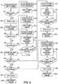
- the position of the RDM shift fork 63 is continuously monitored (S73) and the engine 1 torque output is limited (S72) until the RDM torque lock condition is eliminated and the RDM shift fork 63 reaches its target position (S73). Once the RDM shift fork reaches its target position, the clutch 15 is applied (S74) and the shift is successfully completed (S103).
Landscapes
- Engineering & Computer Science (AREA)
- Mechanical Engineering (AREA)
- General Engineering & Computer Science (AREA)
- Transportation (AREA)
- Automation & Control Theory (AREA)
- Chemical & Material Sciences (AREA)
- Combustion & Propulsion (AREA)
- Control Of Transmission Device (AREA)
- Accessory Devices And Overall Control Thereof (AREA)
- Arrangement And Driving Of Transmission Devices (AREA)
Claims (15)
- Verfahren zum Schalten einer multimodalen Antriebseinheit, umfassend ein Getriebe (2), eine Nebenantriebseinheit (3), die eine erste Vielzahl von Übersetzungsverhältnissen aufweist und mit dem Getriebe (2) verbunden ist, und ein Hinterantriebsmodul (4), das eine zweite Vielzahl von Übersetzungsverhältnissen aufweist und mit der Nebenantriebseinheit (3) verbunden ist, wobei das Verfahren als Reaktion auf eine Schaltanforderung umfasst:Einleiten einer Schaltung in der Nebenantriebseinheit (3) von einem Betrieb in einem ersten Übersetzungsverhältnis der ersten Vielzahl von Übersetzungsverhältnissen in einen Betrieb in einem zweiten Übersetzungsverhältnis der ersten Vielzahl von Übersetzungsverhältnissen; wobei das Verfahren dadurch gekennzeichnet ist, dass es als Reaktion auf die Schaltanforderung des Weiteren umfasst:Überwachen des Fortschritts der Schaltung der Nebenantriebseinheit (3);Zurückweisen der Schaltanforderung, wenn die Nebenantriebseinheit (3) nicht erfolgreich von einem Betrieb in dem ersten Übersetzungsverhältnis der ersten Vielzahl von Übersetzungsverhältnissen in einen Betrieb in dem zweiten Übersetzungsverhältnis der ersten Vielzahl von Übersetzungsverhältnissen schalten kann; undSchalten des Hinterantriebsmoduls (4) von einem Betrieb in einem ersten Übersetzungsverhältnis der zweiten Vielzahl von Übersetzungsverhältnissen in einen Betrieb in einem zweiten Übersetzungsverhältnis der zweiten Vielzahl von Übersetzungsverhältnissen, wenn die Schaltung der Nebenantriebseinheit (3) erfolgreich abgeschlossen ist.
- Verfahren zum Schalten einer multimodalen Antriebseinheit nach Anspruch 1, wobei die zweite Vielzahl von Übersetzungsverhältnissen der ersten Vielzahl von Übersetzungsverhältnissen entspricht und entsprechende Übersetzungsverhältnisse der ersten Vielzahl von Übersetzungsverhältnissen und der zweiten Vielzahl von Übersetzungsverhältnissen gleichzeitig in Eingriff gebracht werden.
- Verfahren zum Schalten einer multimodalen Antriebseinheit nach Anspruch 1, des Weiteren umfassend das Bestimmen, ob mindestens eine Sperrbedingung erfüllt ist vor dem
Einleiten der Schaltung der Nebenantriebseinheit (3) und Zurückweisen der Schaltanforderung, falls die mindestens eine Sperrbedingung nicht erfüllt ist;
wobei die mindestens eine Sperrbedingung aus der einen Zustand des Antiblockiersystems, einen Zustand des Traktionssteuersystems, einen Zustand des elektronischen Stabilitätssteuerprogramms, einen Zustand der Fahrzeugzündung, Fahrzeuggeschwindigkeit, Zustand des Getriebes (2), Anwendung der Fahrzeugbremse und Drehzahl des Motors (1) umfassenden Gruppe ausgewählt ist. - Verfahren zum Schalten einer multimodalen Antriebseinheit nach Anspruch 1, des Weiteren umfassend das Feststellen der vorhandenen Drehmomentblockierung innerhalb der Nebenantriebseinheit (3), nachdem die Schaltung in der Nebenantriebseinheit (3) eingeleitet ist, und Zurückweisen der Schaltanforderung, falls eine Drehmomentblockierung festgestellt wird.
- Verfahren zum Schalten einer multimodalen Antriebseinheit nach Anspruch 1, des Weiteren umfassend:Feststellen einer vorhandenen Zahnhemmung innerhalb der Nebenantriebseinheit (3), nachdem die Schaltung in der Nebenantriebseinheit (3) eingeleitet ist;Begrenzen des auf die Nebenantriebseinheit (3) aufgebrachten Drehmoments, bis die Schaltung der Nebenantriebseinheit abgeschlossen ist, falls eine Drehmomentblockierung festgestellt wird; undAbschließen der Schaltung der Nebenantriebseinheit (3), falls keine Zahnhemmung festgestellt wird.
- Verfahren zum Schalten einer multimodalen Antriebseinheit nach Anspruch 1, des Weiteren umfassend:Feststellen der vorhandenen Drehmomentblockierung innerhalb des Hinterantriebsmoduls (4), nachdem die Schaltung in dem Hinterantriebsmodul (4) eingeleitet ist; undBegrenzen des auf das Hinterantriebsmodul (4) aufgebrachten Drehmoments, bis die Schaltung des Hinterantriebsmoduls (4) abgeschlossen ist, falls eine Drehmomentblockierung festgestellt wird.
- Verfahren zum Schalten einer multimodalen Antriebseinheit nach Anspruch 1, des Weiteren umfassend:Feststellen der vorhandenen Zahnhemmung innerhalb des Hinterantriebsmoduls (4), nachdem die Schaltung in dem Hinterantriebsmodul (4) eingeleitet ist;Begrenzen des auf das Hinterantriebsmodul (4) aufgebrachten Drehmoments, bis die Schaltung des Hinterantriebsmoduls (4) abgeschlossen ist, falls eine Zahnhemmung festgestellt wird; undAbschließen der Schaltung des Hinterantriebsmoduls (4), falls keine Zahnhemmung festgestellt wird.
- Verfahren zum Schalten einer multimodalen Antriebseinheit nach Anspruch 1, wobei die Antriebseinheit des Weiteren eine Kupplung (15) aufweist, die selektiv die Nebenantriebseinheit (3) mit dem Hinterantriebsmodul (4) verbindet, und wobei das Verfahren außerdem das Abschalten der Kupplung (15) vor Einleiten der Schaltung in der Nebenantriebseinheit (3) umfasst; und wobei die Kupplung (15) betätigt wird, nachdem die Schaltung des Hinterantriebsmoduls (4) abgeschlossen ist.
- Verfahren zum Betreiben einer multimodalen Antriebseinheit mit einem Getriebe (2), einer Nebenantriebseinheit (3), die eine erste Vielzahl von Übersetzungsverhältnissen aufweist und mit dem Getriebe (2) verbunden ist, und einem Hinterantriebsmodul (4), das eine zweite Vielzahl von Übersetzungsverhältnissen aufweist und mit der Nebenantriebseinheit (3) verbunden ist, wobei die erste Vielzahl von Übersetzungsverhältnissen die Übersetzungsverhältnisse aufweist, die der zweiten Vielzahl von Übersetzungsverhältnissen entspricht, umfassend:Empfangen einer Schaltanforderung; wobei das Verfahren dadurch gekennzeichnet ist, dass es außerdem umfasst:Bestimmen, ob mindestens eine Sperrbedingung erfüllt ist;Zurückweisen der Schaltanforderung, falls die mindestens eine Sperrbedingung nicht erfüllt ist;Einleiten einer Schaltung in der Nebenantriebseinheit (3) von einem Betrieb in einem ersten Übersetzungsverhältnis der ersten Vielzahl von Übersetzungsverhältnissen zum Betrieb in einem zweiten Übersetzungsverhältnis der ersten Vielzahl von Übersetzungsverhältnissen, falls die mindestens eine Sperrbedingung erfüllt ist;Überwachen des Fortschritts der Schaltung der Nebenantriebseinheit (3);Zurückweisen der Schaltanforderung, wenn die Nebenantriebseinheit (3) nicht erfolgreich schalten kann von einem Betrieb in dem ersten Übersetzungsverhältnis der ersten Vielzahl von Übersetzungsverhältnissen zum Betrieb in das zweite Übersetzungsverhältnis der ersten Vielzahl von Übersetzungsverhältnissen; undSchalten des Hinterantriebsmoduls von einem Betrieb in einem ersten Übersetzungsverhältnis der zweiten Vielzahl von Übersetzungsverhältnissen, das dem ersten Übersetzungsverhältnis der ersten Vielzahl von Übersetzungsverhältnissen entspricht, zum Betrieb in einem zweiten Übersetzungsverhältnis der zweiten Vielzahl von Übersetzungsverhältnissen, das dem zweiten Übersetzungsverhältnis der ersten Vielzahl von Übersetzungsverhältnissen entspricht, wenn die Schaltung der Nebenantriebseinheit (3) erfolgreich abgeschlossen ist.
- Verfahren zum Betreiben einer multimodalen Antriebseinheit nach Anspruch 9, wobei die mindestens eine Sperrbedingung aus der einen Zustand des Antiblockiersystems, einen Zustand des Traktionssteuersystems, einen Zustand des elektronischen Stabilitätssteuerprogramms, einen Zustand der Fahrzeugzündung, Fahrzeuggeschwindigkeit, Zustand des Getriebes (2), Anwendung der Fahrzeugbremse und Drehzahl des Motors (1) umfassenden Gruppe ausgewählt ist.
- Verfahren zum Betreiben einer multimodalen Antriebseinheit nach Anspruch 9, des Weiteren umfassend:Feststellen der vorhandenen Drehmomentblockierung innerhalb der Nebenantriebseinheit (3), nachdem die Schaltung in der Nebenantriebseinheit (3) eingeleitet ist, und Zurückweisen der Schaltanforderung, falls eine Drehmomentblockierung festgestellt wird;wenn keine Drehmomentblockierung festgestellt wird, Feststellen der vorhandenen Zahnhemmung innerhalb der Nebenantriebseinheit (3);Begrenzen des auf die Nebenantriebseinheit (3) aufgebrachten Drehmoments, bis die Schaltung der Nebenantriebseinheit (3) abgeschlossen ist, falls eine Zahnhemmung festgestellt wird; undAbschließen der Schaltung der Nebenantriebseinheit (3), falls keine Zahnhemmung festgestellt wird.
- Verfahren zum Betreiben einer multimodalen Antriebseinheit nach Anspruch 11, des Weiteren umfassend:Feststellen der vorhandenen Drehmomentblockierung innerhalb des Hinterantriebsmoduls (4), nachdem die Schaltung in dem Hinterantriebsmodul (4) eingeleitet ist; undBegrenzen des auf das Hinterantriebsmodul (4) aufgebrachten Drehmoments, bis die Schaltung des Hinterantriebsmoduls (4) abgeschlossen ist, falls eine Drehmomentblockierung festgestellt wird;falls keine Drehmomentblockierung festgestellt wird, Feststellen der vorhandenen Zahnhemmung innerhalb des Hinterantriebsmoduls (4);Begrenzen des auf das Hinterantriebsmodul (4) aufgebrachten Drehmoments, bis die Schaltung des Hinterantriebsmoduls (4) abgeschlossen ist, falls eine Zahnhemmung festgestellt wird; undAbschließen der Schaltung des Hinterantriebsmoduls (4), falls keine Zahnhemmung festgestellt wird.
- Verfahren zum Betreiben einer multimodalen Antriebseinheit nach Anspruch 9, wobei die Antriebseinheit des Weiteren eine Kupplung (15) aufweist, die selektiv die Nebenantriebseinheit (3) mit dem Hinterantriebsmodul (4) verbindet, und wobei das Verfahren außerdem umfasst:Abschalten der Kupplung (15) vor dem Einleiten der Schaltung in der Nebenantriebseinheit (3); undBetätigen der Kupplung (15), nachdem der Schaltung des Hinterantriebsmoduls (4) abgeschlossen ist.
- Verfahren zum Betreiben einer multimodalen Antriebseinheit nach Anspruch 13, des Weiteren umfassend:Feststellen der vorhandenen Drehmomentblockierung innerhalb der Nebenantriebseinheit (3), nachdem die Schaltung in der Nebenantriebseinheit (3) eingeleitet ist;Einleiten der Schaltung in der Nebenantriebseinheit (3) zumindest ein zweites Mal, falls eine Drehmomentblockierung innerhalb der Nebenantriebseinheit (3) festgestellt wird, und Zurückweisen der Schaltanforderung, falls eine Drehmomentblockierung festgestellt wird, nach der zumindest zweiten eingeleiteten Schaltung in der Nebenantriebseinheit (3);falls keine Drehmomentblockierung festgestellt wird, Feststellen der vorhandenen Zahnhemmung innerhalb der Nebenantriebseinheit (3);Begrenzen des auf die Nebenantriebseinheit (3) aufgebrachten Drehmoments, bis die Schaltung der Nebenantriebseinheit (3) abgeschlossen ist, falls eine Zahnhemmung festgestellt wird; undAbschließen der Schaltung der Nebenantriebseinheit (3), falls keine Zahnhemmung festgestellt wird.
- Verfahren zum Betreiben einer multimodalen Antriebseinheit nach Anspruch 14, des Weiteren umfassend:Feststellen der vorhandenen Drehmomentblockierung innerhalb des Hinterantriebsmoduls (4), nachdem die Schaltung in dem Hinterantriebsmodul (4) eingeleitet ist; undBegrenzen des auf das Hinterantriebsmodul (4) aufgebrachten Drehmoments, bis die Schaltung des Hinterantriebsmoduls (4) abgeschlossen ist, falls eine Drehmomentblockierung festgestellt wird;falls keine Drehmomentblockierung festgestellt wird, Feststellen der vorhandenen Zahnhemmung innerhalb des Hinterantriebsmoduls (4);Begrenzen des auf das Hinterantriebsmodul (4) aufgebrachten Drehmoments, bis die Schaltung des Hinterantriebsmoduls (4) abgeschlossen ist, falls eine Zahnhemmung festgestellt wird; undAbschließen der Schaltung, falls keine Zahnhemmung festgestellt wird;wobei die Schaltanforderung zurückgewiesen wird, es sei denn, alle Sperrbedingungen sind erfüllt.
Applications Claiming Priority (2)
| Application Number | Priority Date | Filing Date | Title |
|---|---|---|---|
| US13/525,449 US8712651B2 (en) | 2012-06-18 | 2012-06-18 | Control strategies for a multi-mode drive system |
| PCT/US2013/045138 WO2013191960A1 (en) | 2012-06-18 | 2013-06-11 | Control strategies for a multi-mode drive system |
Publications (2)
| Publication Number | Publication Date |
|---|---|
| EP2861446A1 EP2861446A1 (de) | 2015-04-22 |
| EP2861446B1 true EP2861446B1 (de) | 2018-11-28 |
Family
ID=48741513
Family Applications (1)
| Application Number | Title | Priority Date | Filing Date |
|---|---|---|---|
| EP13733141.9A Active EP2861446B1 (de) | 2012-06-18 | 2013-06-11 | Steuerungsstrategien für ein multimodales antriebssystem |
Country Status (6)
| Country | Link |
|---|---|
| US (1) | US8712651B2 (de) |
| EP (1) | EP2861446B1 (de) |
| CN (1) | CN104781097B (de) |
| BR (1) | BR112014031488A2 (de) |
| MX (1) | MX349352B (de) |
| WO (1) | WO2013191960A1 (de) |
Families Citing this family (5)
| Publication number | Priority date | Publication date | Assignee | Title |
|---|---|---|---|---|
| DE112011105939B4 (de) * | 2011-12-12 | 2018-12-13 | Toyota Jidosha Kabushiki Kaisha | Lenkvorrichtung |
| EP3073224B1 (de) | 2015-03-27 | 2019-05-08 | Panasonic Automotive & Industrial Systems Europe GmbH | Sensordatenfusion basierend auf digitalen kartendaten |
| WO2018156706A1 (en) * | 2017-02-22 | 2018-08-30 | Dana Heavy Vehicle Systems Group, Llc | Commercial vehicle with electric driven axle |
| CN106915315B (zh) * | 2017-03-24 | 2019-03-08 | 潍柴动力股份有限公司 | 一种自动互锁的控制方法及装置 |
| US10902687B2 (en) * | 2018-02-01 | 2021-01-26 | Gkn Automotive Ltd. | Power transfer unit maintenance |
Family Cites Families (18)
| Publication number | Priority date | Publication date | Assignee | Title |
|---|---|---|---|---|
| GB2190049B (en) | 1986-05-02 | 1989-11-29 | Kubota Ltd | Four wheel drive vehicle |
| GB9412805D0 (en) * | 1994-06-25 | 1994-08-17 | Eaton Corp | Engagement fault degraded mode control |
| KR100186857B1 (ko) * | 1995-02-03 | 1999-04-01 | . | 차량 자동 변속기의 변속제어용 마찰결합장치의 동시 해방 및 결합 제어 장치 |
| JP3191631B2 (ja) * | 1995-08-09 | 2001-07-23 | トヨタ自動車株式会社 | 車両用直結クラッチのスリップ制御装置 |
| US5904632A (en) | 1997-03-21 | 1999-05-18 | New Venture Gear, Inc. | Full-time four-wheel drive transmission |
| JP3503411B2 (ja) * | 1997-04-16 | 2004-03-08 | 日産自動車株式会社 | 締結要素の制御装置 |
| JP3495262B2 (ja) | 1998-09-03 | 2004-02-09 | 株式会社クボタ | 作業車の走行用変速操作装置 |
| JP2000127789A (ja) | 1998-10-26 | 2000-05-09 | Toyota Motor Corp | 4輪駆動車 |
| US6223592B1 (en) * | 1998-11-13 | 2001-05-01 | Eaton Corporation | Independent control of transmission-side and engine-side retarding devices during ratio changes |
| JP3552710B2 (ja) * | 2002-09-04 | 2004-08-11 | 日産自動車株式会社 | 車両の駆動力制御装置 |
| JP2004144108A (ja) * | 2002-10-21 | 2004-05-20 | Nissan Diesel Motor Co Ltd | 多段変速機の変速制御装置 |
| US7261673B2 (en) | 2002-10-21 | 2007-08-28 | Nissan Diesel Motor Co., Ltd. | Apparatus for controlling automatic transmission |
| JP2008185168A (ja) * | 2007-01-31 | 2008-08-14 | Toyota Motor Corp | 自動変速機の制御装置 |
| JP2008189110A (ja) | 2007-02-05 | 2008-08-21 | Mazda Motor Corp | 四輪駆動車の動力伝達装置 |
| US8095287B2 (en) | 2007-08-30 | 2012-01-10 | Chrysler Group Llc | Methods and systems for controlling an axle disconnect device for an all-wheel drive vehicle |
| EP2063153B1 (de) * | 2007-11-21 | 2013-01-23 | Honda Motor Co., Ltd. | Kupplungssteuerungssystem für Getriebe |
| JP5285684B2 (ja) * | 2010-12-16 | 2013-09-11 | 富士重工業株式会社 | 無段変速機の制御装置 |
| JP5786648B2 (ja) * | 2011-10-28 | 2015-09-30 | トヨタ自動車株式会社 | 変速制御装置および変速制御方法 |
-
2012
- 2012-06-18 US US13/525,449 patent/US8712651B2/en active Active
-
2013
- 2013-06-11 MX MX2014015907A patent/MX349352B/es active IP Right Grant
- 2013-06-11 BR BR112014031488A patent/BR112014031488A2/pt active Search and Examination
- 2013-06-11 CN CN201380032033.8A patent/CN104781097B/zh active Active
- 2013-06-11 EP EP13733141.9A patent/EP2861446B1/de active Active
- 2013-06-11 WO PCT/US2013/045138 patent/WO2013191960A1/en not_active Ceased
Non-Patent Citations (1)
| Title |
|---|
| None * |
Also Published As
| Publication number | Publication date |
|---|---|
| CN104781097B (zh) | 2017-05-17 |
| MX2014015907A (es) | 2015-03-03 |
| MX349352B (es) | 2017-07-25 |
| CN104781097A (zh) | 2015-07-15 |
| US8712651B2 (en) | 2014-04-29 |
| US20130338887A1 (en) | 2013-12-19 |
| WO2013191960A1 (en) | 2013-12-27 |
| BR112014031488A2 (pt) | 2017-06-27 |
| EP2861446A1 (de) | 2015-04-22 |
Similar Documents
| Publication | Publication Date | Title |
|---|---|---|
| EP2796310B1 (de) | Verteilergetriebe | |
| EP3299235B1 (de) | Steuerungsvorrichtung für ein fahrzeug mit allradantrieb und steuerungsverfahren für ein fahrzeug mit allradantrieb | |
| RU2540197C1 (ru) | Устройство передачи мощности транспортного средства | |
| CN103260928A (zh) | 多模式牵引系统 | |
| US8712651B2 (en) | Control strategies for a multi-mode drive system | |
| US9925869B2 (en) | Two-speed transfer case with non-synchronized range shift mechanism and on-the-move range shift control system | |
| EP3446912A1 (de) | Antriebsmodusumschaltvorrichtung für ein fahrzeug mit allradantrieb | |
| US9470308B2 (en) | Method and apparatus for controlling the engagement of an input gear with an output gear | |
| CN107020951B (zh) | 分动器 | |
| JP4894609B2 (ja) | 車両用駆動力制御装置 | |
| JP2017043247A (ja) | 4wd車用トランスファの制御装置 | |
| JP2010247603A (ja) | 変速機ユニットの制御装置 | |
| JP4496714B2 (ja) | トランスファの駆動モード切替制御装置 | |
| US10781764B2 (en) | Target torque control device and target torque control method | |
| JPH0629091Y2 (ja) | 4輪駆動車の切換制御装置 | |
| JP2006348984A (ja) | 副変速機付き自動変速機の制御装置 | |
| JP2017039340A (ja) | 4wd車用トランスファの制御装置 | |
| JPH01164630A (ja) | 自動変速機を備えた4輪駆動車の制御装置 | |
| JP2007137124A (ja) | 車両の制御装置 | |
| JP2016199088A (ja) | 4輪駆動車両の制御装置 | |
| JPS6328727A (ja) | 四輪駆動装置の制御方法 | |
| JPH0237040A (ja) | 4輪駆動車の前後輪差動制御装置 |
Legal Events
| Date | Code | Title | Description |
|---|---|---|---|
| PUAI | Public reference made under article 153(3) epc to a published international application that has entered the european phase |
Free format text: ORIGINAL CODE: 0009012 |
|
| 17P | Request for examination filed |
Effective date: 20141204 |
|
| AK | Designated contracting states |
Kind code of ref document: A1 Designated state(s): AL AT BE BG CH CY CZ DE DK EE ES FI FR GB GR HR HU IE IS IT LI LT LU LV MC MK MT NL NO PL PT RO RS SE SI SK SM TR |
|
| AX | Request for extension of the european patent |
Extension state: BA ME |
|
| RIN1 | Information on inventor provided before grant (corrected) |
Inventor name: THOMPSON, AARON, E. Inventor name: GAPSKI, MICHAEL, W. Inventor name: SCHMANSKI, DONALD, F. Inventor name: KUBINA, JOSEPH, E. Inventor name: PACHUCKI, KENNETH, M. Inventor name: SILBERT, RICHARD, S. |
|
| DAX | Request for extension of the european patent (deleted) | ||
| RAP1 | Party data changed (applicant data changed or rights of an application transferred) |
Owner name: FCA US LLC |
|
| GRAP | Despatch of communication of intention to grant a patent |
Free format text: ORIGINAL CODE: EPIDOSNIGR1 |
|
| STAA | Information on the status of an ep patent application or granted ep patent |
Free format text: STATUS: GRANT OF PATENT IS INTENDED |
|
| INTG | Intention to grant announced |
Effective date: 20180711 |
|
| GRAS | Grant fee paid |
Free format text: ORIGINAL CODE: EPIDOSNIGR3 |
|
| GRAA | (expected) grant |
Free format text: ORIGINAL CODE: 0009210 |
|
| STAA | Information on the status of an ep patent application or granted ep patent |
Free format text: STATUS: THE PATENT HAS BEEN GRANTED |
|
| AK | Designated contracting states |
Kind code of ref document: B1 Designated state(s): AL AT BE BG CH CY CZ DE DK EE ES FI FR GB GR HR HU IE IS IT LI LT LU LV MC MK MT NL NO PL PT RO RS SE SI SK SM TR |
|
| REG | Reference to a national code |
Ref country code: CH Ref legal event code: EP |
|
| REG | Reference to a national code |
Ref country code: AT Ref legal event code: REF Ref document number: 1069804 Country of ref document: AT Kind code of ref document: T Effective date: 20181215 |
|
| REG | Reference to a national code |
Ref country code: DE Ref legal event code: R096 Ref document number: 602013047437 Country of ref document: DE |
|
| REG | Reference to a national code |
Ref country code: IE Ref legal event code: FG4D |
|
| REG | Reference to a national code |
Ref country code: NL Ref legal event code: MP Effective date: 20181128 |
|
| REG | Reference to a national code |
Ref country code: LT Ref legal event code: MG4D |
|
| REG | Reference to a national code |
Ref country code: AT Ref legal event code: MK05 Ref document number: 1069804 Country of ref document: AT Kind code of ref document: T Effective date: 20181128 |
|
| PG25 | Lapsed in a contracting state [announced via postgrant information from national office to epo] |
Ref country code: ES Free format text: LAPSE BECAUSE OF FAILURE TO SUBMIT A TRANSLATION OF THE DESCRIPTION OR TO PAY THE FEE WITHIN THE PRESCRIBED TIME-LIMIT Effective date: 20181128 Ref country code: LV Free format text: LAPSE BECAUSE OF FAILURE TO SUBMIT A TRANSLATION OF THE DESCRIPTION OR TO PAY THE FEE WITHIN THE PRESCRIBED TIME-LIMIT Effective date: 20181128 Ref country code: AT Free format text: LAPSE BECAUSE OF FAILURE TO SUBMIT A TRANSLATION OF THE DESCRIPTION OR TO PAY THE FEE WITHIN THE PRESCRIBED TIME-LIMIT Effective date: 20181128 Ref country code: FI Free format text: LAPSE BECAUSE OF FAILURE TO SUBMIT A TRANSLATION OF THE DESCRIPTION OR TO PAY THE FEE WITHIN THE PRESCRIBED TIME-LIMIT Effective date: 20181128 Ref country code: IS Free format text: LAPSE BECAUSE OF FAILURE TO SUBMIT A TRANSLATION OF THE DESCRIPTION OR TO PAY THE FEE WITHIN THE PRESCRIBED TIME-LIMIT Effective date: 20190328 Ref country code: NO Free format text: LAPSE BECAUSE OF FAILURE TO SUBMIT A TRANSLATION OF THE DESCRIPTION OR TO PAY THE FEE WITHIN THE PRESCRIBED TIME-LIMIT Effective date: 20190228 Ref country code: LT Free format text: LAPSE BECAUSE OF FAILURE TO SUBMIT A TRANSLATION OF THE DESCRIPTION OR TO PAY THE FEE WITHIN THE PRESCRIBED TIME-LIMIT Effective date: 20181128 Ref country code: HR Free format text: LAPSE BECAUSE OF FAILURE TO SUBMIT A TRANSLATION OF THE DESCRIPTION OR TO PAY THE FEE WITHIN THE PRESCRIBED TIME-LIMIT Effective date: 20181128 Ref country code: BG Free format text: LAPSE BECAUSE OF FAILURE TO SUBMIT A TRANSLATION OF THE DESCRIPTION OR TO PAY THE FEE WITHIN THE PRESCRIBED TIME-LIMIT Effective date: 20190228 |
|
| PG25 | Lapsed in a contracting state [announced via postgrant information from national office to epo] |
Ref country code: SE Free format text: LAPSE BECAUSE OF FAILURE TO SUBMIT A TRANSLATION OF THE DESCRIPTION OR TO PAY THE FEE WITHIN THE PRESCRIBED TIME-LIMIT Effective date: 20181128 Ref country code: PT Free format text: LAPSE BECAUSE OF FAILURE TO SUBMIT A TRANSLATION OF THE DESCRIPTION OR TO PAY THE FEE WITHIN THE PRESCRIBED TIME-LIMIT Effective date: 20190328 Ref country code: AL Free format text: LAPSE BECAUSE OF FAILURE TO SUBMIT A TRANSLATION OF THE DESCRIPTION OR TO PAY THE FEE WITHIN THE PRESCRIBED TIME-LIMIT Effective date: 20181128 Ref country code: GR Free format text: LAPSE BECAUSE OF FAILURE TO SUBMIT A TRANSLATION OF THE DESCRIPTION OR TO PAY THE FEE WITHIN THE PRESCRIBED TIME-LIMIT Effective date: 20190301 Ref country code: RS Free format text: LAPSE BECAUSE OF FAILURE TO SUBMIT A TRANSLATION OF THE DESCRIPTION OR TO PAY THE FEE WITHIN THE PRESCRIBED TIME-LIMIT Effective date: 20181128 |
|
| PG25 | Lapsed in a contracting state [announced via postgrant information from national office to epo] |
Ref country code: NL Free format text: LAPSE BECAUSE OF FAILURE TO SUBMIT A TRANSLATION OF THE DESCRIPTION OR TO PAY THE FEE WITHIN THE PRESCRIBED TIME-LIMIT Effective date: 20181128 |
|
| PG25 | Lapsed in a contracting state [announced via postgrant information from national office to epo] |
Ref country code: PL Free format text: LAPSE BECAUSE OF FAILURE TO SUBMIT A TRANSLATION OF THE DESCRIPTION OR TO PAY THE FEE WITHIN THE PRESCRIBED TIME-LIMIT Effective date: 20181128 Ref country code: CZ Free format text: LAPSE BECAUSE OF FAILURE TO SUBMIT A TRANSLATION OF THE DESCRIPTION OR TO PAY THE FEE WITHIN THE PRESCRIBED TIME-LIMIT Effective date: 20181128 Ref country code: DK Free format text: LAPSE BECAUSE OF FAILURE TO SUBMIT A TRANSLATION OF THE DESCRIPTION OR TO PAY THE FEE WITHIN THE PRESCRIBED TIME-LIMIT Effective date: 20181128 |
|
| REG | Reference to a national code |
Ref country code: DE Ref legal event code: R097 Ref document number: 602013047437 Country of ref document: DE |
|
| PG25 | Lapsed in a contracting state [announced via postgrant information from national office to epo] |
Ref country code: SK Free format text: LAPSE BECAUSE OF FAILURE TO SUBMIT A TRANSLATION OF THE DESCRIPTION OR TO PAY THE FEE WITHIN THE PRESCRIBED TIME-LIMIT Effective date: 20181128 Ref country code: RO Free format text: LAPSE BECAUSE OF FAILURE TO SUBMIT A TRANSLATION OF THE DESCRIPTION OR TO PAY THE FEE WITHIN THE PRESCRIBED TIME-LIMIT Effective date: 20181128 Ref country code: SM Free format text: LAPSE BECAUSE OF FAILURE TO SUBMIT A TRANSLATION OF THE DESCRIPTION OR TO PAY THE FEE WITHIN THE PRESCRIBED TIME-LIMIT Effective date: 20181128 Ref country code: EE Free format text: LAPSE BECAUSE OF FAILURE TO SUBMIT A TRANSLATION OF THE DESCRIPTION OR TO PAY THE FEE WITHIN THE PRESCRIBED TIME-LIMIT Effective date: 20181128 |
|
| PLBE | No opposition filed within time limit |
Free format text: ORIGINAL CODE: 0009261 |
|
| STAA | Information on the status of an ep patent application or granted ep patent |
Free format text: STATUS: NO OPPOSITION FILED WITHIN TIME LIMIT |
|
| PG25 | Lapsed in a contracting state [announced via postgrant information from national office to epo] |
Ref country code: SI Free format text: LAPSE BECAUSE OF FAILURE TO SUBMIT A TRANSLATION OF THE DESCRIPTION OR TO PAY THE FEE WITHIN THE PRESCRIBED TIME-LIMIT Effective date: 20181128 |
|
| 26N | No opposition filed |
Effective date: 20190829 |
|
| PG25 | Lapsed in a contracting state [announced via postgrant information from national office to epo] |
Ref country code: MC Free format text: LAPSE BECAUSE OF FAILURE TO SUBMIT A TRANSLATION OF THE DESCRIPTION OR TO PAY THE FEE WITHIN THE PRESCRIBED TIME-LIMIT Effective date: 20181128 |
|
| REG | Reference to a national code |
Ref country code: CH Ref legal event code: PL |
|
| REG | Reference to a national code |
Ref country code: BE Ref legal event code: MM Effective date: 20190630 |
|
| PG25 | Lapsed in a contracting state [announced via postgrant information from national office to epo] |
Ref country code: TR Free format text: LAPSE BECAUSE OF FAILURE TO SUBMIT A TRANSLATION OF THE DESCRIPTION OR TO PAY THE FEE WITHIN THE PRESCRIBED TIME-LIMIT Effective date: 20181128 |
|
| PG25 | Lapsed in a contracting state [announced via postgrant information from national office to epo] |
Ref country code: IE Free format text: LAPSE BECAUSE OF NON-PAYMENT OF DUE FEES Effective date: 20190611 |
|
| PG25 | Lapsed in a contracting state [announced via postgrant information from national office to epo] |
Ref country code: LI Free format text: LAPSE BECAUSE OF NON-PAYMENT OF DUE FEES Effective date: 20190630 Ref country code: LU Free format text: LAPSE BECAUSE OF NON-PAYMENT OF DUE FEES Effective date: 20190611 Ref country code: CH Free format text: LAPSE BECAUSE OF NON-PAYMENT OF DUE FEES Effective date: 20190630 Ref country code: BE Free format text: LAPSE BECAUSE OF NON-PAYMENT OF DUE FEES Effective date: 20190630 |
|
| PG25 | Lapsed in a contracting state [announced via postgrant information from national office to epo] |
Ref country code: CY Free format text: LAPSE BECAUSE OF FAILURE TO SUBMIT A TRANSLATION OF THE DESCRIPTION OR TO PAY THE FEE WITHIN THE PRESCRIBED TIME-LIMIT Effective date: 20181128 |
|
| PG25 | Lapsed in a contracting state [announced via postgrant information from national office to epo] |
Ref country code: MT Free format text: LAPSE BECAUSE OF FAILURE TO SUBMIT A TRANSLATION OF THE DESCRIPTION OR TO PAY THE FEE WITHIN THE PRESCRIBED TIME-LIMIT Effective date: 20181128 Ref country code: HU Free format text: LAPSE BECAUSE OF FAILURE TO SUBMIT A TRANSLATION OF THE DESCRIPTION OR TO PAY THE FEE WITHIN THE PRESCRIBED TIME-LIMIT; INVALID AB INITIO Effective date: 20130611 |
|
| PG25 | Lapsed in a contracting state [announced via postgrant information from national office to epo] |
Ref country code: MK Free format text: LAPSE BECAUSE OF FAILURE TO SUBMIT A TRANSLATION OF THE DESCRIPTION OR TO PAY THE FEE WITHIN THE PRESCRIBED TIME-LIMIT Effective date: 20181128 |
|
| PGFP | Annual fee paid to national office [announced via postgrant information from national office to epo] |
Ref country code: DE Payment date: 20250627 Year of fee payment: 13 |
|
| PGFP | Annual fee paid to national office [announced via postgrant information from national office to epo] |
Ref country code: GB Payment date: 20250627 Year of fee payment: 13 |
|
| PGFP | Annual fee paid to national office [announced via postgrant information from national office to epo] |
Ref country code: FR Payment date: 20250625 Year of fee payment: 13 |
|
| PGFP | Annual fee paid to national office [announced via postgrant information from national office to epo] |
Ref country code: IT Payment date: 20250619 Year of fee payment: 13 |