EP2850239B1 - Wäschebehandlungsmaschine - Google Patents
Wäschebehandlungsmaschine Download PDFInfo
- Publication number
- EP2850239B1 EP2850239B1 EP13720949.0A EP13720949A EP2850239B1 EP 2850239 B1 EP2850239 B1 EP 2850239B1 EP 13720949 A EP13720949 A EP 13720949A EP 2850239 B1 EP2850239 B1 EP 2850239B1
- Authority
- EP
- European Patent Office
- Prior art keywords
- foam
- laundry
- drum
- treatment machine
- seal
- Prior art date
- Legal status (The legal status is an assumption and is not a legal conclusion. Google has not performed a legal analysis and makes no representation as to the accuracy of the status listed.)
- Active
Links
Images

Classifications
-
- D—TEXTILES; PAPER
- D06—TREATMENT OF TEXTILES OR THE LIKE; LAUNDERING; FLEXIBLE MATERIALS NOT OTHERWISE PROVIDED FOR
- D06F—LAUNDERING, DRYING, IRONING, PRESSING OR FOLDING TEXTILE ARTICLES
- D06F37/00—Details specific to washing machines covered by groups D06F21/00 - D06F25/00
- D06F37/26—Casings; Tubs
- D06F37/266—Gaskets mounted between tub and casing around the loading opening
-
- D—TEXTILES; PAPER
- D06—TREATMENT OF TEXTILES OR THE LIKE; LAUNDERING; FLEXIBLE MATERIALS NOT OTHERWISE PROVIDED FOR
- D06F—LAUNDERING, DRYING, IRONING, PRESSING OR FOLDING TEXTILE ARTICLES
- D06F58/00—Domestic laundry dryers
- D06F58/02—Domestic laundry dryers having dryer drums rotating about a horizontal axis
- D06F58/04—Details
Definitions
- the invention relates to a laundry treatment machine with a laundry drum, which is rotatably mounted in a housing about a drum axis, wherein between a peripheral part of the laundry drum rotating laundry drum and a fixed surface of a component of the housing, an annular foam gasket is arranged on the surface of the Component fixed and sealingly guided on the laundry drum and is provided on at least one of its annular end faces with an air and / or water-impermeable coating.
- the foam gasket has a structure having a layer of a needle punched nonwoven fabric and a layer of closed cell foam, which foam performs the sealing function.
- Laundry treatment machines are generally known as washing machines, as machines for the professional cleaning of textiles or as tumble dryers.
- the laundry drum of such laundry machines designed as washing machines can have an end-side charging opening and in this case is mounted on its front side facing away from the charging opening via a shaft journal in the housing of the laundry treatment machine.
- types of washing machines are known in which the laundry drum rotates about a substantially vertically extending drum axis, wherein the laundry drum is charged from above.
- washing machines which can be loaded from above with laundry items can also have a laundry drum mounted above a horizontal drum axis, which can then be opened and re-closed for loading with laundry items on its outer jacket.
- laundry treatment machines are designed as a tumble dryer, in which the laundry drum heated process air is supplied.
- This can optionally be an exhaust air dryer or a condensation dryer.
- Modern condensation dryers are usually operated with a heat pump.
- tumble dryers the laundry drum is usually arranged in the housing such that it rotates about a horizontally extending drum axis and has a front feed opening.
- Such a laundry drum of a clothes dryer is usually guided at its rear end wall by means of a hinge bearing on the housing and also stored at its front end using a bearing plate by means of rollers in the housing.
- a laundry treatment machine of the type described above is known from the EP 2 072 657 A1 , It is designed as a laundry dryer laundry treatment machine, in which a bearing plate is provided with a groove for receiving a drum seal.
- the groove bottom of this groove should be provided with a wedge-shaped toothing, said toothing should prevent co-rotation of the seal. It is intended to make this seal either foam or a combination of foam and felt.
- From the DE 195 03 367 C2 a likewise designed as a clothes dryer laundry treatment machine, in which a channel for the process air of the clothes dryer is connected via provided in the front-side rear wall of the laundry drum openings with the interior of the laundry drum.
- the heated process air then flows through the interior of the laundry drum, thereby absorbing the moisture of the laundry items present in the laundry drum, whereupon the process air leaves again in the region of a door closing a charging opening of the laundry drum via a channel provided in this area.
- a sealing ring should be provided between a bottom wall of the laundry drum and a cup-shaped flange connected to the housing, which radially surrounds the region of the feed line of the process air into the laundry drum.
- this sealing ring should be formed as a profile ring on which an elastic lip is provided. Both the main body of the profile ring and the elastic lip should be made of rubber. Alternatively, it is also provided to produce a corresponding sealing ring for the supply of process air from a nitrile rubber material and a felt strip attached thereto. The felt strip should lie sealingly against a bead of the laundry drum.
- a clothes dryer with a seal arrangement between the tumble dryer housing and a rear end wall of the laundry drum known in which a felt ring seal is glued into a U-shaped receiving groove made of a rubber or plastic mechanical seal carrier.
- This mechanical seal carrier is formed in a lying S-shape, wherein a foam ring is applied to an underside of the U-shaped receiving groove.
- the foam ring is to transmit the contact forces required to achieve the sealing function on the felt ring seal and is guided for this purpose at an angling of a foot part and at an end portion of a web of the mechanical seal carrier.
- the foam seal should be made of an open-cell foam and abut a sliding surface on a contact surface of the peripheral part of the laundry drum;
- the sliding surface should be made of a teflon-soaked felt.
- the sliding surface is made of a teflon impregnated felt, can be achieved by the advantageous sliding properties between the foam seal and the laundry drum.
- the foam gasket should be arranged in an annular groove of the bearing plate or the housing, so that the foam gasket has sufficient lateral guidance.
- the foam ring according to this publication should not assume any sealing function but only pretension the felt-ring seal in the direction of the sealing surface. Therefore, a sliding surface is not formed directly on the foam ring, which is also to be avoided according to this document.
- the distance to the foam ring extending sliding ring seal carrier is to reduce its thermal load by the dry air flow, which is why a corresponding space is provided between an end face of the foam ring and the web of the mechanical seal carrier.
- the other documents DE 195 03 367 C2 and DE 10 2005 009 230 B4 show seal assemblies in which the respective seal is not made of foam.
- the friction occurring between the foam gasket and the frontal or peripheral rotationally symmetric part of the laundry drum is reduced by the open cell foam having a low compression hardness so that the elastic foam gasket created thereby bears against the rotationally symmetric part of the laundry drum with little biasing force. Furthermore, the friction is reduced by the fact that the voltage applied to the contact surface of the part of the laundry drum surface of the foam seal is formed as a sliding surface.
- the foam seal may also be provided on its radially inner lateral surface with a corresponding coating.
- the open-cell foam of the foam seal should have a foam density defined by a density of 25 to 45 kg / m 3 .
- the compressive strength should be 1.8 to 5 kPa.
- the laundry drum can be rotatably mounted about a substantially horizontal drum axis and have a feed opening on one end face.
- a foam seal between a fixed to a front wall of the laundry treating machine bearing plate and the laundry drum is provided and / or provided a foam seal between a rear edge of the laundry drum and a rear wall of the housing. It depends on the area in which the region or channel connected to the interior of the laundry drum is to be sealed relative to the interior of the housing.
- a corresponding open-cell foam gasket with an air and / or water impermeable coating and a sliding surface for use in a laundry dryer designed as a laundry machine.
- a foam seal between a rear wall of the tumble dryer and the peripheral part of the laundry drum and / or a foam seal between a front edge of the laundry drum and a housing connected to the front wall bearing plate are provided.
- the sealed on its surface foam seal prevents in this case that the entering or leaving the laundry drum process air can get into the housing interior of the clothes dryer. A leak in the area of the entry of the process air Otherwise, this leakage would lead to a deterioration of the dry result.
- the inventively embodied foam gasket ensures that these problems can not occur, in addition to the effective sealing of inlet and outlet of the process air and an operation of the tumble dryer can be achieved with low friction losses.
- the coating should be formed as a film, which is attached in a corresponding manner at least on one of the two end faces of the foam seal. It will preferably be the end face of the foam gasket, which faces the space or channel to be sealed.
- it is possible to produce the coating by melting the annular surface of the foam seal.
- the radially inner surface of the foam seal may be provided by melting with a coating, if this proves to be useful.
- These may be flexible elastomers, e.g. Silicone or neoprene act.
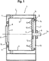
- FIG. 1 1 designates a clothes dryer intended for use in a household, which has a housing 2 and a laundry drum 3 which is rotatably mounted therein about a drum axis 3a.
- the laundry drum 3 is mounted in a front area via a roller bearing 4 in the housing 2 and guided on its rear wall 5 via a spherical plain bearing 6 on the housing 2.
- the laundry drum 3 has a front-side charging opening 7, which is substantially aligned with a charging opening 8 provided in the housing 2.
- the charging opening 8 of the housing 2 can be closed by a door 9, wherein in the region of this door 9 a through the housing 2 and the washing drum 3 limited exhaust duct 10 is provided for emerging from the laundry drum 3 process air.
- the exhaust air duct 10 is sealed radially by a first foam seal 11.
- openings 12 are provided in the rear wall 5 of the laundry drum, is passed through the heated process air into the interior of the laundry drum 3.
- These heated process air is conveyed by means of a process air blower not shown and passes via a rear wall 5 adjacent supply air duct 13 and via the aforementioned openings 12 in the interior of the laundry drum 3, flows through this, wherein it absorbs moisture from the laundry, and then passes through the feed opening 7 in the direction of the exhaust duct 10 from the laundry drum.
- the supply air duct 13 is bounded by the rear wall 5 and the adjacent wall portion of the housing 2, wherein it is radially sealed in this area by a spatially arranged between the housing 2 and the laundry drum 3 second foam seal 14.
- a spatially arranged between the housing 2 and the laundry drum 3 second foam seal 14 For this purpose, from the laundry drum 3 from both axially and radially inwardly facing edge 15 from which cooperates with a provided on the foam seal 14 sliding surface 16, that is guided on this sliding.
- this foam seal 14 With regard to the arrangement and the design of this foam seal 14 is on the FIG. 2 referenced, in which this is shown enlarged.
- the foam seal 11 should be formed in this way and arranged in at least similar form between the laundry drum 3 and the housing. In this case, however, the foam seal 11 may be received by a bearing shield, not shown.
- FIG. 2 shows how the edge 15 abuts the sliding surface formed as a sliding surface 16 of the foam seal 14.
- the foam seal 14 is arranged in a groove 17 of an outgoing from the housing 2 component 18.
- the sliding layer of the sliding surface 16 is made of a Teflon-impregnated felt, whereby optimum sliding properties against the edge 15 of the laundry drum are provided.
- the foam gasket 14 is provided at its annular end faces 19 and 20 each with a coating 21 and 22. Since the foam seal 14 is made of an open-cell foam with a relatively low compression hardness, the sliding surface 15 is located with little radial bias on the edge 15 of the laundry drum 3, whereby the friction is further reduced.
- the open-pored foam for this purpose is permeable to air, so that a use of such after FIG. 1 provided foam seal 11 without the coatings of the invention would cause moist exhaust air from the Exhaust duct 10 passes into the interior of the housing 2, so that moisture could be reflected there.
- the foam gasket 14 were similarly made from an open cell foam and not coated on its surface, some of the supply air could escape through this foam gasket 14, which is not available for laundry drying.
- the solution according to the invention therefore provides, in addition to an increase in the elasticity of the corresponding foam seal 11 or 14, its air and / or water impermeable coating 21 and 22. This can be designed as a film, melting of the foam or applied in the liquid state sealant.
Landscapes
- Engineering & Computer Science (AREA)
- Textile Engineering (AREA)
- Detail Structures Of Washing Machines And Dryers (AREA)
- Treatment Of Fiber Materials (AREA)
Applications Claiming Priority (2)
| Application Number | Priority Date | Filing Date | Title |
|---|---|---|---|
| DE102012207977A DE102012207977A1 (de) | 2012-05-14 | 2012-05-14 | Wäschebehandlungsmaschine |
| PCT/EP2013/059448 WO2013171091A1 (de) | 2012-05-14 | 2013-05-07 | Wäschebehandlungsmaschine |
Publications (2)
| Publication Number | Publication Date |
|---|---|
| EP2850239A1 EP2850239A1 (de) | 2015-03-25 |
| EP2850239B1 true EP2850239B1 (de) | 2016-04-06 |
Family
ID=48325720
Family Applications (1)
| Application Number | Title | Priority Date | Filing Date |
|---|---|---|---|
| EP13720949.0A Active EP2850239B1 (de) | 2012-05-14 | 2013-05-07 | Wäschebehandlungsmaschine |
Country Status (6)
| Country | Link |
|---|---|
| EP (1) | EP2850239B1 (pl) |
| CN (1) | CN104321482B (pl) |
| DE (1) | DE102012207977A1 (pl) |
| PL (1) | PL2850239T3 (pl) |
| RU (1) | RU2597293C2 (pl) |
| WO (1) | WO2013171091A1 (pl) |
Families Citing this family (16)
| Publication number | Priority date | Publication date | Assignee | Title |
|---|---|---|---|---|
| EP2829652A1 (de) * | 2013-07-24 | 2015-01-28 | Vereinigte Filzfabriken AG | Dichtung für einen Wäschetrockner |
| DE102014202237A1 (de) * | 2014-02-07 | 2015-08-13 | BSH Bosch und Siemens Hausgeräte GmbH | Wäschebehandlungsmaschine mit einer Wäschetrommel |
| DE102014205636A1 (de) * | 2014-03-26 | 2015-10-01 | Aktiebolaget Skf | Dichtung |
| WO2016144758A1 (en) * | 2015-03-06 | 2016-09-15 | Hg LAUNDRY SYSTEMS, LLC | Washing machine with positive pressure moisture extraction |
| CN106283561B (zh) * | 2015-05-29 | 2019-12-17 | 无锡小天鹅电器有限公司 | 干衣机 |
| ITUA20161734A1 (it) * | 2016-03-16 | 2017-09-16 | I F T Manifatture S R L | Dispositivo a guarnizione |
| EP3469135B1 (en) | 2016-06-08 | 2020-01-22 | Arçelik Anonim Sirketi | A washer / dryer wherein air and water tightness is provided between the tub and the drum |
| CN106049001B (zh) * | 2016-07-29 | 2020-01-17 | 无锡小天鹅电器有限公司 | 干衣机 |
| CN108729167A (zh) * | 2017-04-20 | 2018-11-02 | 青岛海尔滚筒洗衣机有限公司 | 一种干衣机 |
| US11866881B2 (en) | 2018-07-30 | 2024-01-09 | Lg Electronics Inc. | Clothing treatment apparatus |
| EP3741898B1 (de) * | 2019-05-21 | 2023-08-02 | BSH Hausgeräte GmbH | Vorrichtung zum waschen und trocknen von zu waschenden und zu trocknenden objekten und verfahren zum betreiben einer solchen vorrichtung |
| DE102020205594A1 (de) | 2020-05-04 | 2021-11-04 | BSH Hausgeräte GmbH | Wäschebehandlungsmaschine mit einem gehäuse und einer wärmepumpe |
| CN114438705B (zh) * | 2020-11-04 | 2025-08-26 | 青岛海尔洗涤电器有限公司 | 滚筒洗衣机 |
| US11795601B2 (en) | 2020-11-10 | 2023-10-24 | Whirlpool Corporation | Maximizing the dry rate of clothes tumbling combination washer/dryer with a seal |
| US11846059B2 (en) | 2021-01-04 | 2023-12-19 | Whirlpool Corporation | Controlling process air bypass around the drum in combo wash-dry system |
| KR102561643B1 (ko) * | 2023-03-20 | 2023-07-28 | 박상옥 | 드럼건조기의 회전드럼 단부용 개스킷 |
Family Cites Families (14)
| Publication number | Priority date | Publication date | Assignee | Title |
|---|---|---|---|---|
| US3637224A (en) * | 1969-02-27 | 1972-01-25 | Fedders Corp | Annular sealing ring |
| US3816942A (en) * | 1972-07-24 | 1974-06-18 | Maytag Co | Bulkhead seal for clothes dryer |
| DE8136238U1 (de) * | 1981-12-12 | 1982-05-27 | G. Bauknecht Gmbh, 7000 Stuttgart | Waeschetrockner |
| DE8214637U1 (de) * | 1982-05-19 | 1982-08-05 | Licentia Patent-Verwaltungs-Gmbh, 6000 Frankfurt | Dichtung fuer einen trommeltrockner |
| US5363569A (en) * | 1993-03-11 | 1994-11-15 | White Consolidated Industries, Inc. | Bearing and seal assembly for clothes dryer drum |
| DE19503367C2 (de) | 1995-02-02 | 2002-04-25 | Bsh Bosch Siemens Hausgeraete | Dichtungsanordnung für einen Haushalt-Wäschetrockner |
| US20020004128A1 (en) * | 1998-05-28 | 2002-01-10 | Anthony Forte | Method and system for sealing electrical connection using sealant-impregnated foam |
| JP4912588B2 (ja) * | 2004-12-24 | 2012-04-11 | 日東電工株式会社 | エチレン・プロピレン・ジエンゴム連続気泡発泡体 |
| DE102005009230B4 (de) | 2005-02-25 | 2008-12-24 | Jensen-Senking Gmbh | Trocknungsanlage mit einer Trocknerdichtung und Zentriermitteln |
| US20070044342A1 (en) * | 2005-08-01 | 2007-03-01 | John Burns | Dryer seal |
| JP4857197B2 (ja) * | 2007-06-04 | 2012-01-18 | 日立アプライアンス株式会社 | ドラム式洗濯機 |
| DE102007061983A1 (de) | 2007-12-21 | 2009-06-25 | BSH Bosch und Siemens Hausgeräte GmbH | Lagerschild für einen Wäschetrockner und Wäschetrockner |
| DE102008043348A1 (de) * | 2008-10-31 | 2010-05-06 | BSH Bosch und Siemens Hausgeräte GmbH | Anordnung mit zumindest zwei luftführenden Teilen und einer dazwischen angeordneten Dichtung sowie Hausgerät mit einer derartigen Anordnung |
| CN201546067U (zh) * | 2009-10-30 | 2010-08-11 | 南京乐金熊猫电器有限公司 | 滚筒洗衣机密封圈 |
-
2012
- 2012-05-14 DE DE102012207977A patent/DE102012207977A1/de not_active Withdrawn
-
2013
- 2013-05-07 RU RU2014146259/12A patent/RU2597293C2/ru not_active IP Right Cessation
- 2013-05-07 EP EP13720949.0A patent/EP2850239B1/de active Active
- 2013-05-07 PL PL13720949.0T patent/PL2850239T3/pl unknown
- 2013-05-07 WO PCT/EP2013/059448 patent/WO2013171091A1/de not_active Ceased
- 2013-05-07 CN CN201380025360.0A patent/CN104321482B/zh active Active
Also Published As
| Publication number | Publication date |
|---|---|
| DE102012207977A1 (de) | 2013-11-14 |
| CN104321482A (zh) | 2015-01-28 |
| WO2013171091A1 (de) | 2013-11-21 |
| RU2597293C2 (ru) | 2016-09-10 |
| RU2014146259A (ru) | 2016-07-10 |
| PL2850239T3 (pl) | 2016-10-31 |
| CN104321482B (zh) | 2016-11-16 |
| EP2850239A1 (de) | 2015-03-25 |
Similar Documents
| Publication | Publication Date | Title |
|---|---|---|
| EP2850239B1 (de) | Wäschebehandlungsmaschine | |
| DE2844051C3 (de) | Verfahren zum Kühlen eines Walzenpaars sowie Kalander zur Durchführung des Verfahrens | |
| EP2649230A2 (de) | Dichtungsmanschette für eine waschmaschine | |
| EP2399040A1 (de) | Abdichtung für ein wälzlager | |
| EP3741898B1 (de) | Vorrichtung zum waschen und trocknen von zu waschenden und zu trocknenden objekten und verfahren zum betreiben einer solchen vorrichtung | |
| DE102010029491B4 (de) | Baugruppe und Haushaltswäschetrockner mit dieser Baugruppe | |
| DE102005009230B4 (de) | Trocknungsanlage mit einer Trocknerdichtung und Zentriermitteln | |
| DE102011082849A1 (de) | Walze mit Walzenbezug | |
| DE2462294A1 (de) | Umwaelztrommeltrockner | |
| EP3361000B1 (de) | Vorrichtung zur entfeuchtung, elektrogerät mit einer solchen vorrichtung und verfahren zur entfeuchtung | |
| DE19962257B4 (de) | Wäschebehandlungsmaschine | |
| DE102015007447A1 (de) | Dichtungsanordnung | |
| DE19742787A1 (de) | Haube | |
| DE102009001323A1 (de) | Vorrichtung und Verfahren zum Schleudern von Wäsche | |
| DE102008035315A1 (de) | Dichteinrichtung | |
| WO2023156486A1 (de) | Dichtungsanordnung, insbesondere gleitringdichtung, vorzugsweise für den einsatz in kühlmittelaggregaten | |
| DE102011080728A1 (de) | Pressband für Schuhpressvorrichtung | |
| DE102014202237A1 (de) | Wäschebehandlungsmaschine mit einer Wäschetrommel | |
| EP1541742B1 (de) | Wäschetrockner mit einer Rollenlagerung | |
| AT507389B1 (de) | Metallbandkalander | |
| DE102012205187A1 (de) | Presswalze für eine Maschine zur Herstellung einer Faserstoffbahn | |
| DE202011004475U1 (de) | Anordnung zum Konditionieren eines Gewebes in einer Faserbahnmaschine | |
| EP2123825B1 (de) | Verfahren zum Öffnen eines Langspalts | |
| DE102005007775A1 (de) | Dichtungsvorrichtung | |
| DE102016123030A1 (de) | Waschtrockner |
Legal Events
| Date | Code | Title | Description |
|---|---|---|---|
| PUAI | Public reference made under article 153(3) epc to a published international application that has entered the european phase |
Free format text: ORIGINAL CODE: 0009012 |
|
| 17P | Request for examination filed |
Effective date: 20141215 |
|
| AK | Designated contracting states |
Kind code of ref document: A1 Designated state(s): AL AT BE BG CH CY CZ DE DK EE ES FI FR GB GR HR HU IE IS IT LI LT LU LV MC MK MT NL NO PL PT RO RS SE SI SK SM TR |
|
| AX | Request for extension of the european patent |
Extension state: BA ME |
|
| DAX | Request for extension of the european patent (deleted) | ||
| GRAP | Despatch of communication of intention to grant a patent |
Free format text: ORIGINAL CODE: EPIDOSNIGR1 |
|
| INTG | Intention to grant announced |
Effective date: 20151102 |
|
| GRAS | Grant fee paid |
Free format text: ORIGINAL CODE: EPIDOSNIGR3 |
|
| GRAA | (expected) grant |
Free format text: ORIGINAL CODE: 0009210 |
|
| AK | Designated contracting states |
Kind code of ref document: B1 Designated state(s): AL AT BE BG CH CY CZ DE DK EE ES FI FR GB GR HR HU IE IS IT LI LT LU LV MC MK MT NL NO PL PT RO RS SE SI SK SM TR |
|
| REG | Reference to a national code |
Ref country code: GB Ref legal event code: FG4D Free format text: NOT ENGLISH |
|
| REG | Reference to a national code |
Ref country code: AT Ref legal event code: REF Ref document number: 787959 Country of ref document: AT Kind code of ref document: T Effective date: 20160415 Ref country code: CH Ref legal event code: EP |
|
| REG | Reference to a national code |
Ref country code: IE Ref legal event code: FG4D Free format text: LANGUAGE OF EP DOCUMENT: GERMAN |
|
| REG | Reference to a national code |
Ref country code: DE Ref legal event code: R096 Ref document number: 502013002485 Country of ref document: DE |
|
| REG | Reference to a national code |
Ref country code: LT Ref legal event code: MG4D Ref country code: NL Ref legal event code: MP Effective date: 20160406 |
|
| PG25 | Lapsed in a contracting state [announced via postgrant information from national office to epo] |
Ref country code: BE Free format text: LAPSE BECAUSE OF NON-PAYMENT OF DUE FEES Effective date: 20160531 |
|
| PG25 | Lapsed in a contracting state [announced via postgrant information from national office to epo] |
Ref country code: NL Free format text: LAPSE BECAUSE OF FAILURE TO SUBMIT A TRANSLATION OF THE DESCRIPTION OR TO PAY THE FEE WITHIN THE PRESCRIBED TIME-LIMIT Effective date: 20160406 |
|
| PG25 | Lapsed in a contracting state [announced via postgrant information from national office to epo] |
Ref country code: FI Free format text: LAPSE BECAUSE OF FAILURE TO SUBMIT A TRANSLATION OF THE DESCRIPTION OR TO PAY THE FEE WITHIN THE PRESCRIBED TIME-LIMIT Effective date: 20160406 Ref country code: IS Free format text: LAPSE BECAUSE OF FAILURE TO SUBMIT A TRANSLATION OF THE DESCRIPTION OR TO PAY THE FEE WITHIN THE PRESCRIBED TIME-LIMIT Effective date: 20160806 Ref country code: LT Free format text: LAPSE BECAUSE OF FAILURE TO SUBMIT A TRANSLATION OF THE DESCRIPTION OR TO PAY THE FEE WITHIN THE PRESCRIBED TIME-LIMIT Effective date: 20160406 Ref country code: NO Free format text: LAPSE BECAUSE OF FAILURE TO SUBMIT A TRANSLATION OF THE DESCRIPTION OR TO PAY THE FEE WITHIN THE PRESCRIBED TIME-LIMIT Effective date: 20160706 |
|
| PG25 | Lapsed in a contracting state [announced via postgrant information from national office to epo] |
Ref country code: GR Free format text: LAPSE BECAUSE OF FAILURE TO SUBMIT A TRANSLATION OF THE DESCRIPTION OR TO PAY THE FEE WITHIN THE PRESCRIBED TIME-LIMIT Effective date: 20160707 Ref country code: SE Free format text: LAPSE BECAUSE OF FAILURE TO SUBMIT A TRANSLATION OF THE DESCRIPTION OR TO PAY THE FEE WITHIN THE PRESCRIBED TIME-LIMIT Effective date: 20160406 Ref country code: LV Free format text: LAPSE BECAUSE OF FAILURE TO SUBMIT A TRANSLATION OF THE DESCRIPTION OR TO PAY THE FEE WITHIN THE PRESCRIBED TIME-LIMIT Effective date: 20160406 Ref country code: PT Free format text: LAPSE BECAUSE OF FAILURE TO SUBMIT A TRANSLATION OF THE DESCRIPTION OR TO PAY THE FEE WITHIN THE PRESCRIBED TIME-LIMIT Effective date: 20160808 Ref country code: RS Free format text: LAPSE BECAUSE OF FAILURE TO SUBMIT A TRANSLATION OF THE DESCRIPTION OR TO PAY THE FEE WITHIN THE PRESCRIBED TIME-LIMIT Effective date: 20160406 Ref country code: HR Free format text: LAPSE BECAUSE OF FAILURE TO SUBMIT A TRANSLATION OF THE DESCRIPTION OR TO PAY THE FEE WITHIN THE PRESCRIBED TIME-LIMIT Effective date: 20160406 Ref country code: ES Free format text: LAPSE BECAUSE OF FAILURE TO SUBMIT A TRANSLATION OF THE DESCRIPTION OR TO PAY THE FEE WITHIN THE PRESCRIBED TIME-LIMIT Effective date: 20160406 |
|
| PG25 | Lapsed in a contracting state [announced via postgrant information from national office to epo] |
Ref country code: IT Free format text: LAPSE BECAUSE OF FAILURE TO SUBMIT A TRANSLATION OF THE DESCRIPTION OR TO PAY THE FEE WITHIN THE PRESCRIBED TIME-LIMIT Effective date: 20160406 |
|
| REG | Reference to a national code |
Ref country code: CH Ref legal event code: PL |
|
| REG | Reference to a national code |
Ref country code: DE Ref legal event code: R097 Ref document number: 502013002485 Country of ref document: DE |
|
| PG25 | Lapsed in a contracting state [announced via postgrant information from national office to epo] |
Ref country code: EE Free format text: LAPSE BECAUSE OF FAILURE TO SUBMIT A TRANSLATION OF THE DESCRIPTION OR TO PAY THE FEE WITHIN THE PRESCRIBED TIME-LIMIT Effective date: 20160406 Ref country code: SK Free format text: LAPSE BECAUSE OF FAILURE TO SUBMIT A TRANSLATION OF THE DESCRIPTION OR TO PAY THE FEE WITHIN THE PRESCRIBED TIME-LIMIT Effective date: 20160406 Ref country code: DK Free format text: LAPSE BECAUSE OF FAILURE TO SUBMIT A TRANSLATION OF THE DESCRIPTION OR TO PAY THE FEE WITHIN THE PRESCRIBED TIME-LIMIT Effective date: 20160406 Ref country code: CH Free format text: LAPSE BECAUSE OF NON-PAYMENT OF DUE FEES Effective date: 20160531 Ref country code: CZ Free format text: LAPSE BECAUSE OF FAILURE TO SUBMIT A TRANSLATION OF THE DESCRIPTION OR TO PAY THE FEE WITHIN THE PRESCRIBED TIME-LIMIT Effective date: 20160406 Ref country code: RO Free format text: LAPSE BECAUSE OF FAILURE TO SUBMIT A TRANSLATION OF THE DESCRIPTION OR TO PAY THE FEE WITHIN THE PRESCRIBED TIME-LIMIT Effective date: 20160406 Ref country code: LI Free format text: LAPSE BECAUSE OF NON-PAYMENT OF DUE FEES Effective date: 20160531 Ref country code: MC Free format text: LAPSE BECAUSE OF FAILURE TO SUBMIT A TRANSLATION OF THE DESCRIPTION OR TO PAY THE FEE WITHIN THE PRESCRIBED TIME-LIMIT Effective date: 20160406 |
|
| PLBE | No opposition filed within time limit |
Free format text: ORIGINAL CODE: 0009261 |
|
| STAA | Information on the status of an ep patent application or granted ep patent |
Free format text: STATUS: NO OPPOSITION FILED WITHIN TIME LIMIT |
|
| REG | Reference to a national code |
Ref country code: IE Ref legal event code: MM4A |
|
| PG25 | Lapsed in a contracting state [announced via postgrant information from national office to epo] |
Ref country code: SM Free format text: LAPSE BECAUSE OF FAILURE TO SUBMIT A TRANSLATION OF THE DESCRIPTION OR TO PAY THE FEE WITHIN THE PRESCRIBED TIME-LIMIT Effective date: 20160406 |
|
| REG | Reference to a national code |
Ref country code: FR Ref legal event code: ST Effective date: 20170131 |
|
| 26N | No opposition filed |
Effective date: 20170110 |
|
| PG25 | Lapsed in a contracting state [announced via postgrant information from national office to epo] |
Ref country code: FR Free format text: LAPSE BECAUSE OF NON-PAYMENT OF DUE FEES Effective date: 20160606 |
|
| PG25 | Lapsed in a contracting state [announced via postgrant information from national office to epo] |
Ref country code: SI Free format text: LAPSE BECAUSE OF FAILURE TO SUBMIT A TRANSLATION OF THE DESCRIPTION OR TO PAY THE FEE WITHIN THE PRESCRIBED TIME-LIMIT Effective date: 20160406 Ref country code: IE Free format text: LAPSE BECAUSE OF NON-PAYMENT OF DUE FEES Effective date: 20160507 |
|
| PG25 | Lapsed in a contracting state [announced via postgrant information from national office to epo] |
Ref country code: HU Free format text: LAPSE BECAUSE OF FAILURE TO SUBMIT A TRANSLATION OF THE DESCRIPTION OR TO PAY THE FEE WITHIN THE PRESCRIBED TIME-LIMIT; INVALID AB INITIO Effective date: 20130507 |
|
| PG25 | Lapsed in a contracting state [announced via postgrant information from national office to epo] |
Ref country code: MK Free format text: LAPSE BECAUSE OF FAILURE TO SUBMIT A TRANSLATION OF THE DESCRIPTION OR TO PAY THE FEE WITHIN THE PRESCRIBED TIME-LIMIT Effective date: 20160406 Ref country code: CY Free format text: LAPSE BECAUSE OF FAILURE TO SUBMIT A TRANSLATION OF THE DESCRIPTION OR TO PAY THE FEE WITHIN THE PRESCRIBED TIME-LIMIT Effective date: 20160406 Ref country code: LU Free format text: LAPSE BECAUSE OF NON-PAYMENT OF DUE FEES Effective date: 20160507 Ref country code: MT Free format text: LAPSE BECAUSE OF FAILURE TO SUBMIT A TRANSLATION OF THE DESCRIPTION OR TO PAY THE FEE WITHIN THE PRESCRIBED TIME-LIMIT Effective date: 20160406 |
|
| PG25 | Lapsed in a contracting state [announced via postgrant information from national office to epo] |
Ref country code: BG Free format text: LAPSE BECAUSE OF FAILURE TO SUBMIT A TRANSLATION OF THE DESCRIPTION OR TO PAY THE FEE WITHIN THE PRESCRIBED TIME-LIMIT Effective date: 20160406 |
|
| PG25 | Lapsed in a contracting state [announced via postgrant information from national office to epo] |
Ref country code: TR Free format text: LAPSE BECAUSE OF FAILURE TO SUBMIT A TRANSLATION OF THE DESCRIPTION OR TO PAY THE FEE WITHIN THE PRESCRIBED TIME-LIMIT Effective date: 20160406 Ref country code: AL Free format text: LAPSE BECAUSE OF FAILURE TO SUBMIT A TRANSLATION OF THE DESCRIPTION OR TO PAY THE FEE WITHIN THE PRESCRIBED TIME-LIMIT Effective date: 20160406 |
|
| REG | Reference to a national code |
Ref country code: DE Ref legal event code: R084 Ref document number: 502013002485 Country of ref document: DE |
|
| REG | Reference to a national code |
Ref country code: AT Ref legal event code: MM01 Ref document number: 787959 Country of ref document: AT Kind code of ref document: T Effective date: 20180507 |
|
| PG25 | Lapsed in a contracting state [announced via postgrant information from national office to epo] |
Ref country code: AT Free format text: LAPSE BECAUSE OF NON-PAYMENT OF DUE FEES Effective date: 20180507 |
|
| PGFP | Annual fee paid to national office [announced via postgrant information from national office to epo] |
Ref country code: PL Payment date: 20230421 Year of fee payment: 11 |
|
| PGFP | Annual fee paid to national office [announced via postgrant information from national office to epo] |
Ref country code: GB Payment date: 20230522 Year of fee payment: 11 |
|
| GBPC | Gb: european patent ceased through non-payment of renewal fee |
Effective date: 20240507 |
|
| PG25 | Lapsed in a contracting state [announced via postgrant information from national office to epo] |
Ref country code: GB Free format text: LAPSE BECAUSE OF NON-PAYMENT OF DUE FEES Effective date: 20240507 |
|
| PGFP | Annual fee paid to national office [announced via postgrant information from national office to epo] |
Ref country code: DE Payment date: 20250531 Year of fee payment: 13 |
|
| PG25 | Lapsed in a contracting state [announced via postgrant information from national office to epo] |
Ref country code: PL Free format text: LAPSE BECAUSE OF NON-PAYMENT OF DUE FEES Effective date: 20240507 |