EP2844453B1 - Injection mold having a simplified evaporative cooling system or a simplified cooling system with exotic cooling fluids - Google Patents
Injection mold having a simplified evaporative cooling system or a simplified cooling system with exotic cooling fluids Download PDFInfo
- Publication number
- EP2844453B1 EP2844453B1 EP13723615.4A EP13723615A EP2844453B1 EP 2844453 B1 EP2844453 B1 EP 2844453B1 EP 13723615 A EP13723615 A EP 13723615A EP 2844453 B1 EP2844453 B1 EP 2844453B1
- Authority
- EP
- European Patent Office
- Prior art keywords
- mold
- cooling
- support plate
- assembly
- prior
- Prior art date
- Legal status (The legal status is an assumption and is not a legal conclusion. Google has not performed a legal analysis and makes no representation as to the accuracy of the status listed.)
- Active
Links
Images


Classifications
-
- B—PERFORMING OPERATIONS; TRANSPORTING
- B29—WORKING OF PLASTICS; WORKING OF SUBSTANCES IN A PLASTIC STATE IN GENERAL
- B29C—SHAPING OR JOINING OF PLASTICS; SHAPING OF MATERIAL IN A PLASTIC STATE, NOT OTHERWISE PROVIDED FOR; AFTER-TREATMENT OF THE SHAPED PRODUCTS, e.g. REPAIRING
- B29C33/00—Moulds or cores; Details thereof or accessories therefor
- B29C33/02—Moulds or cores; Details thereof or accessories therefor with incorporated heating or cooling means
- B29C33/04—Moulds or cores; Details thereof or accessories therefor with incorporated heating or cooling means using liquids, gas or steam
- B29C33/046—Moulds or cores; Details thereof or accessories therefor with incorporated heating or cooling means using liquids, gas or steam using gas
-
- B—PERFORMING OPERATIONS; TRANSPORTING
- B29—WORKING OF PLASTICS; WORKING OF SUBSTANCES IN A PLASTIC STATE IN GENERAL
- B29C—SHAPING OR JOINING OF PLASTICS; SHAPING OF MATERIAL IN A PLASTIC STATE, NOT OTHERWISE PROVIDED FOR; AFTER-TREATMENT OF THE SHAPED PRODUCTS, e.g. REPAIRING
- B29C35/00—Heating, cooling or curing, e.g. crosslinking or vulcanising; Apparatus therefor
- B29C35/16—Cooling
-
- B—PERFORMING OPERATIONS; TRANSPORTING
- B29—WORKING OF PLASTICS; WORKING OF SUBSTANCES IN A PLASTIC STATE IN GENERAL
- B29C—SHAPING OR JOINING OF PLASTICS; SHAPING OF MATERIAL IN A PLASTIC STATE, NOT OTHERWISE PROVIDED FOR; AFTER-TREATMENT OF THE SHAPED PRODUCTS, e.g. REPAIRING
- B29C45/00—Injection moulding, i.e. forcing the required volume of moulding material through a nozzle into a closed mould; Apparatus therefor
- B29C45/17—Component parts, details or accessories; Auxiliary operations
- B29C45/72—Heating or cooling
- B29C45/73—Heating or cooling of the mould
- B29C45/7306—Control circuits therefor
-
- B—PERFORMING OPERATIONS; TRANSPORTING
- B29—WORKING OF PLASTICS; WORKING OF SUBSTANCES IN A PLASTIC STATE IN GENERAL
- B29C—SHAPING OR JOINING OF PLASTICS; SHAPING OF MATERIAL IN A PLASTIC STATE, NOT OTHERWISE PROVIDED FOR; AFTER-TREATMENT OF THE SHAPED PRODUCTS, e.g. REPAIRING
- B29C45/00—Injection moulding, i.e. forcing the required volume of moulding material through a nozzle into a closed mould; Apparatus therefor
- B29C45/17—Component parts, details or accessories; Auxiliary operations
- B29C45/72—Heating or cooling
- B29C45/73—Heating or cooling of the mould
- B29C45/7312—Construction of heating or cooling fluid flow channels
-
- B—PERFORMING OPERATIONS; TRANSPORTING
- B29—WORKING OF PLASTICS; WORKING OF SUBSTANCES IN A PLASTIC STATE IN GENERAL
- B29C—SHAPING OR JOINING OF PLASTICS; SHAPING OF MATERIAL IN A PLASTIC STATE, NOT OTHERWISE PROVIDED FOR; AFTER-TREATMENT OF THE SHAPED PRODUCTS, e.g. REPAIRING
- B29C45/00—Injection moulding, i.e. forcing the required volume of moulding material through a nozzle into a closed mould; Apparatus therefor
- B29C45/17—Component parts, details or accessories; Auxiliary operations
- B29C45/72—Heating or cooling
- B29C45/73—Heating or cooling of the mould
- B29C45/7337—Heating or cooling of the mould using gas or steam
-
- B—PERFORMING OPERATIONS; TRANSPORTING
- B29—WORKING OF PLASTICS; WORKING OF SUBSTANCES IN A PLASTIC STATE IN GENERAL
- B29K—INDEXING SCHEME ASSOCIATED WITH SUBCLASSES B29B, B29C OR B29D, RELATING TO MOULDING MATERIALS OR TO MATERIALS FOR MOULDS, REINFORCEMENTS, FILLERS OR PREFORMED PARTS, e.g. INSERTS
- B29K2905/00—Use of metals, their alloys or their compounds, as mould material
- B29K2905/02—Aluminium
-
- B—PERFORMING OPERATIONS; TRANSPORTING
- B29—WORKING OF PLASTICS; WORKING OF SUBSTANCES IN A PLASTIC STATE IN GENERAL
- B29K—INDEXING SCHEME ASSOCIATED WITH SUBCLASSES B29B, B29C OR B29D, RELATING TO MOULDING MATERIALS OR TO MATERIALS FOR MOULDS, REINFORCEMENTS, FILLERS OR PREFORMED PARTS, e.g. INSERTS
- B29K2995/00—Properties of moulding materials, reinforcements, fillers, preformed parts or moulds
- B29K2995/0012—Properties of moulding materials, reinforcements, fillers, preformed parts or moulds having particular thermal properties
- B29K2995/0013—Conductive
-
- B—PERFORMING OPERATIONS; TRANSPORTING
- B29—WORKING OF PLASTICS; WORKING OF SUBSTANCES IN A PLASTIC STATE IN GENERAL
- B29L—INDEXING SCHEME ASSOCIATED WITH SUBCLASS B29C, RELATING TO PARTICULAR ARTICLES
- B29L2031/00—Other particular articles
- B29L2031/757—Moulds, cores, dies
Definitions
- the present invention relates to injection molds, more particularly, to injection molds having a simplified evaporative cooling system.
- Injection molding is a technology commonly used for high-volume manufacturing of parts made of meltable material, most commonly of parts made of thermoplastic polymers.
- a plastic resin most often in the form of small beads or pellets, is introduced to an injection molding machine that melts the resin beads under heat, pressure, and shear.
- the now molten resin is forcefully injected into a mold cavity having a particular cavity shape.
- the injected plastic is held under pressure in the mold cavity, cooled, and then removed as a solidified part having a shape that essentially duplicates the cavity shape of the mold.
- the mold itself may have a single cavity or multiple cavities. Each cavity may be connected to a flow channel by a gate, which directs the flow of the molten resin into the cavity.
- a typical injection molding procedure comprises four basic operations: (1) heating the plastic in the injection molding machine to allow it to flow under pressure; (2) injecting the melted plastic into a mold cavity or cavities defined between two mold halves that have been closed; (3) allowing the plastic to cool and harden in the cavity or cavities while under pressure; and (4) opening the mold halves to allow the part to be ejected from the mold.
- the molten plastic resin is injected into the mold cavity and the plastic resin is forcibly pushed through the cavity by the injection molding machine until the plastic resin reaches the location in the cavity furthest from the gate.
- the resulting length and wall thickness of the part is a result of the shape of the mold cavity.
- the molds used in injection molding machines must be capable of withstanding these high melt pressures. Moreover, the material forming the mold must have a fatigue limit that can withstand the maximum cyclic stress for the total number of cycles a mold is expected to run over the course of its lifetime. As a result, mold manufacturers typically form the mold from materials having high hardness, such as tool steels, having greater than 30 Rc, and more often greater than 50 Rc. These high hardness materials are durable and equipped to withstand the high clamping pressures required to keep mold components pressed against one another during the plastic injection process. Additionally, these high hardness materials are better able to resist wear from the repeated contact between molding surfaces and polymer flow.
- High production injection molding machines i.e., class 101 and class 102 molding machines that produce thinwalled consumer products exclusively use molds having a majority of the mold made from the high hardness materials.
- High production injection molding machines typically produce 500,000 parts or more.
- Industrial quality production molds must be designed to produce at least 500,000 parts, preferably more than 1,000,000 parts, more preferably more than 5,000,000 parts, and even more preferably more than 10,000,000 parts.
- These high production injection molding machines have multi cavity molds and complex cooling systems to increase production rates.
- the high hardness materials described above are more capable of withstanding the repeated high pressure clamping and injection operations than lower hardness materials.
- high hardness materials such as most tool steels, have relatively low thermal conductivities, generally less than 34.6 W/m.K (20 BTU/HR FT °F), which leads to long cooling times as heat is transferred from the molten plastic material through the high hardness material to a cooling fluid.
- typical high production injection molding machines having molds made of high hardness materials include relatively complex internal cooling systems that circulate cooling fluid within the mold. These cooling systems accelerate cooling of the molded parts, thus allowing the machine to complete more cycles in a given amount of time, which increases production rates and thus the total amount of molded parts produced.
- these cooling systems add complexity and cost to the injection molds.
- Class 101 molds that run in 400 ton or larger presses are sometimes referred to as "400 class” molds within the industry.
- High hardness materials are generally fairly difficult to machine.
- known high throughput injection molds require extensive machining time and expensive machining equipment to form, and expensive and time consuming post-machining steps to relieve stresses and optimize material hardness. Milling and/or forming cooling channels within these complex molds adds even more time and costs to the manufacture of typical high throughput injection molds.
- cooling channels should be machined as close to the mold cavity surfaces as possible. Additionally, conformal cooling is desirable and most effective. However, machining conformal cooling channels close to molding surfaces is difficult, time consuming, and expensive. Generally, machining cooling channels within about 5 mm of the mold surfaces is considered to be the practical limit. This practical limit reduces cooling efficiency due to material between the cooling fluid and the hot plastic having low thermal conductivity. Conventional machining techniques, along with conventional mold materials (i.e., high hardness and low thermal conductivity) place a lower limit on cycle time and cooling efficiency for a given mold.
- cooling lines close to the mold surfaces requires precise machining of the cooling lines in the molds. Because the molds are supported by mold support plates when placed in a clamping device of the injection molding machine, fluid seals must be located where the cooling lines transition from the mold support plate to the mold (because the fluid circulating systems (e.g., pumps) must be located outside of the molds). These fluid seals may fail, causing cooling fluid to escape. As a result, parts may be incompletely cooled, which produces an inferior part, or the plastic in the mold may be contaminated with cooling fluid, which is also undesirable.
- fluid circulating systems e.g., pumps
- US6290882 discusses an injection mold for optical lenses with mold cavity support blocks mechanically supported and housed within moldhalves. Heat transfer fluid circulation channels are provided in the mold cavity support blocks.
- Embodiments of the present invention generally relate to mold assemblies for producing products by low constant pressure injection molding.
- melt pressure as used herein with respect to melt pressure of a thermoplastic material, means melt pressures in a vicinity of a nozzle of an injection molding machine of 41.4 MPa (6000 Psi) and lower.
- suitable melt pressures include, for example, less than 5000 psi, less than 4500 psi, less than 4000 psi, and less than 3000 psi.
- the melt pressure can be maintained at a substantially constant pressure within the range of about 1000 psi to less than 6000 psi, about 1500 psi to about 5500 psi, about 2000 psi to about 5000 psi, about 2500 psi to about 4500 psi, about 3000 psi to about 4000 psi, and about 3000 psi to less than 6000 psi.
- substantially constant pressure as used herein with respect to a melt pressure of a thermoplastic material, means that deviations from a baseline melt pressure do not produce meaningful changes in physical properties of the thermoplastic material.
- substantially constant pressure' includes, but is not limited to, pressure variations for which viscosity of the melted thermoplastic material do not meaningfully change.
- substantially constant in this respect includes deviations of approximately 30% from a baseline melt pressure.
- a substantially constant pressure of approximately 4600 psi includes pressure fluctuations within the range of about 6000 psi (30% above 4600 psi) to about 3200 psi (30% below 4600 psi).
- a melt pressure is considered substantially constant as long as the melt pressure fluctuates no more than 30% from the recited pressure.
- the substantially constant pressure can fluctuate (either as an increase or decrease) from the melt pressure about 0% to about 30%, about 2% to about 25%, about 4% to about 20%, about 6% to about 15%, and about 8% to about 10%.
- Other suitable fluctuation amounts includes about 0, 2, 4 ,6, 8, 10, 12, 14, 16, 18, 20, 22, 24, 26, 28, and 30%, or any range formed by any of these values for percentage.
- FIG. 1 illustrates an exemplary low constant pressure injection molding apparatus 10 for producing thin-walled parts in high volumes (e.g., a class 101 or 102 injection mold, or an "ultra high productivity mold”).
- the injection molding apparatus 10 generally includes an injection system 12 and a clamping system 14.
- a thermoplastic material may be introduced to the injection system 12 in the form of thermoplastic pellets 16.
- the thermoplastic pellets 16 may be placed into a hopper 18, which feeds the thermoplastic pellets 16 into a heated barrel 20 of the injection system 12.
- the thermoplastic pellets 16, after being fed into the heated barrel 20, may be driven to the end of the heated barrel 20 by a reciprocating screw 22.
- thermoplastic pellets 16 The heating of the heated barrel 20 and the compression of the thermoplastic pellets 16 by the reciprocating screw 22 causes the thermoplastic pellets 16 to melt, forming a molten thermoplastic material 24.
- the molten thermoplastic material is typically processed at a temperature of about 130°C to about 410°C.
- the reciprocating screw 22 forces the molten thermoplastic material 24, toward a nozzle 26 to form a shot of thermoplastic material, which will be injected into a mold cavity 32 of a mold 28.
- the molten thermoplastic material 24 may be injected through a gate 30, which directs the flow of the molten thermoplastic material 24 to the mold cavity 32.
- the mold cavity 32 is formed between first and second mold parts 25, 27 of the mold 28 and the first and second mold parts 25, 27 are held together under pressure by a press or clamping unit 34.
- the press or clamping unit 34 applies a clamping force in the range of approximately 1000 psi to approximately 6000 psi during the molding process to hold the first and second mold parts 25, 27 together while the molten thermoplastic material 24 is injected into the mold cavity 32.
- the clamping system 14 may include a mold frame and a mold base, the mold frame and the mold base being formed from a material having a surface hardness of more than about 165 BHN and preferably less than 260 BHN, although materials having surface hardness BHN values of greater than 260 may be used as long as the material is easily machineable, as discussed further below.
- the reciprocating screw 22 stops traveling forward.
- the molten thermoplastic material 24 takes the form of the mold cavity 32 and the molten thermoplastic material 24 cools inside the mold 28 until the thermoplastic material 24 solidifies.
- the press 34 releases the first and second mold parts 25, 27, the first and second mold parts 25, 27 are separated from one another, and the finished part may be ejected from the mold 28.
- the mold 28 may include a plurality of mold cavities 32 to increase overall production rates.
- a controller 50 is communicatively connected with a sensor 52 and a screw control 36.
- the controller 50 may include a microprocessor, a memory, and one or more communication links.
- the controller 50 may be connected to the sensor 52 and the screw control 36 via wired connections 54, 56, respectively.
- the controller 50 may be connected to the sensor 52 and screw control 56 via a wireless connection, a mechanical connection, a hydraulic connection, a pneumatic connection, or any other type of communication connection known to those having ordinary skill in the art that will allow the controller 50 to communicate with both the sensor 52 and the screw control 36.
- the sensor 52 is a pressure sensor that measures (directly or indirectly) melt pressure of the molten thermoplastic material 24 in the nozzle 26.
- the sensor 52 generates an electrical signal that is transmitted to the controller 50.
- the controller 50 then commands the screw control 36 to advance the screw 22 at a rate that maintains a substantially constant melt pressure of the molten thermoplastic material 24 in the nozzle 26.
- the sensor 52 may directly measure the melt pressure, the sensor 52 may measure other characteristics of the molten thermoplastic material 24, such as temperature, viscosity, flow rate, etc, that are indicative of melt pressure.
- the senor 52 need not be located directly in the nozzle 26, but rather the sensor 52 may be located at any location within the injection system 12 or mold 28 that is fluidly connected with the nozzle 26. If the sensor 52 is not located within the nozzle 26, appropriate correction factors may be applied to the measured characteristic to calculate the melt pressure in the nozzle 26. In yet other embodiments, the sensor 52 need not be fluidly connected with the nozzle. Rather, the sensor could measure clamping force generated by the clamping system 14 at a mold parting line between the first and second mold parts 25, 27.
- a pressure regulating valve (not shown) or a pressure relief valve (not shown) may replace the controller 50 to regulate the melt pressure of the molten thermoplastic material 24. More specifically, the pressure regulating valve and pressure relief valve can prevent overpressurization of the mold 28. Another alternative mechanism for preventing overpressurization of the mold 28 is an alarm that is activated when an overpressurization condition is detected.
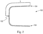
- the molded part 100 is a thin-walled part. Molded parts are generally considered to be thin-walled when a length of a flow channel L divided by a thickness of the flow channel T is greater than 100 (i.e., L/T > 100).
- L/T > 100 The low constant pressure injection molding systems and molds having simplified cooling that are described herein become increasingly advantageous for molding parts as L/T ratios increase, particularly for parts having L/T > 200, or L/T > 250 because the molten thermoplastic material includes a continuous flow front that advances through the mold cavity, which fills the mold cavity with thermoplastic material more consistently than high variable pressure injection molding systems.
- the length of the flow channel L is measured from a gate 102 to a flow channel end 104. Thin-walled parts are especially prevalent in the consumer products industry and healthcare or medical supplies industry.
- Thin-walled parts present certain obstacles in injection molding. For example, the thinness of the flow channel tends to cool the molten thermoplastic material before the material reaches the flow channel end 104. When this happens, the thermoplastic material freezes off and no longer flows, which results in an incomplete part.
- traditional injection molding machines inject the molten thermoplastic material into the mold at very high pressures, typically greater than 103.4 MPa (15,000 Psi) so that the molten thermoplastic material rapidly fills the mold cavity before having a chance to cool and freeze off. This is one reason that manufacturers of the thermoplastic materials teach injecting at very high pressures. Another reason traditional injection molding machines inject molten plastic into the mold at high pressures is the increased shear, which increases flow characteristics, as discussed above. These very high injection pressures require the use of very hard materials to form the mold 28 and the feed system.
- polymers and copolymers comprised of, polyolefins (e.g., polypropylene, polyethylene), thermoplastic elastomers, polyesters (e.g. polyethelyne terephthalate, polybutelene terephthalate), polystyrene, polycarbonate, poly(acrylonitrile-butadiene-styrene), poly(latic acid), polyhydroxyalkanoate, polyamides, polyacetals, ethylene-alpha olefin rubbers, and styrenebutadiene-stryene block copolymers.
- polyolefins e.g., polypropylene, polyethylene
- thermoplastic elastomers e.g. polyethelyne terephthalate, polybutelene terephthalate
- polystyrene polycarbonate
- poly(latic acid) polyhydroxyalkanoate
- thermoplastic material that advances through the mold from a gate to a farthest part of the mold cavity.
- the thermoplastic material remains liquid and flowable at much lower temperatures and pressures than is otherwise believed to be possible in conventional high pressure injection molding systems.
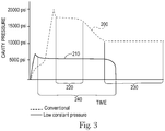
- a typical pressure-time curve for a high pressure injection molding process is illustrated by the dashed line 200.
- a pressure-time curve for the low constant pressure injection molding machine is illustrated by the solid line 210.
- melt pressure is rapidly increased to well over 103.4 MPa (15,000 psi) and then held at a relatively high pressure, more than 15,000 psi, for a first period of time 220.
- the first period of time 220 is the fill time in which molten plastic material flows into the mold cavity.
- the melt pressure is decreased and held at a lower, but still relatively high pressure, 10,000 psi or more, for a second period of time 230.
- the second period of time 230 is a packing time in which the melt pressure is maintained to ensure that all gaps in the mold cavity are back filled.
- the mold cavity in the high pressure injection molding system is filled from the end of the flow channel back to towards the gate.
- plastic in various stages of solidification are packed upon one another, which may cause inconsistencies in the finished product, as discussed above.
- the conventional packing of plastic in various stages of solidification results in some non-ideal material properties, for example, molded-in stresses, sink, and non-optimal optical properties.
- the constant low pressure injection molding system injects the molten plastic material into the mold cavity at a substantially constant low pressure for a single time period 240.
- the injection pressure is less than 41.4 MPa (6000 psi).
- the molten thermoplastic material maintains a continuous melt front that advances through the flow channel from the gate towards the end of the flow channel.
- the plastic material remains relatively uniform at any point along the flow channel, which results in a more uniform and consistent finished product.
- the finished molded parts may form crystalline structures that have better mechanical and/or better optical properties than conventionally molded parts.
- Amorphous polymers may also form structures having superior mechanical and/or optical properties.
- the skin layers of parts molded at low constant pressures exhibit different characteristics than skin layers of conventionally molded parts. As a result, the skin layers of parts molded under low constant pressure can have better optical properties than skin layers of conventionally molded parts.
- the mold 28 illustrated in Fig. 1 may be formed of a material having a milling machining index of greater than 100%, (such as 100-1000%, 100-900%, 100-800%, 100-700%, 100-600%, 100-500%, 100-400%, 100-300%, 100-250%, 100-225%, 100-200%, 100-180%, 100-160%, 100-150%, 100-140%, 100-130%, 100-120%, 100-110%, 120-250%, 120-225%, 120-200%, 120-180%, 120-160%, 120-150%, 120-140%, 120-130%, 140-400%, 150-300%, 160-250%, or 180-225%, or any other range formed by any of these values for percentage), a drilling machining index of greater than 100%, (such as 100-1000%, 100-900%, 100-800%, 100-700%, 100-600%, 100
- the machining indexes are based upon milling, drilling, wire EDM, and sinker EDM tests of various materials. The test methods for determining the machining indices are explained in more detail below. Examples of machining indexes for a sample of materials is compiled below in Table 1.
- easily machineable materials having good thermal conductivity are being applied.
- These materials have thermal conductivities of more than 51 W/m.K (30 BTU/HR FT °F).
- these materials can have thermal conductivities (measured in BTU/HR FT °F ) of 30-200, 30-180, 30-160, 30-140, 30-120, 30-100, 30-80, 30-60, 30-40, 40-200, 60-200, 80-200, 100-200, 120-200, 140-200, 160-200, 180-200, 40-200, 40-180, 40-160, 40-140, 40-120, 40-100, 40-80, 40-60, 50-140, 60-140, 70-140, 80-140, 90-140, 100-140, 110-140, 120-140, 50-130, 50-120, 50-110, 50-100, 50-90, 50-80, 50-70, 50-60, 60-130, 70-130, 80-130, 90-130
- easily machineable materials having good thermal conductivities include, but are not limited to, Alcoa QC-10, Alcan Duramold 500, and Hokotol (available from Aleris). Materials with good thermal conductivity more efficiently transmit heat from the thermoplastic material out of the mold. As a result, more simple cooling systems may be used.
- Multi-cavity molds generally include a feed manifold 60 that directs molten thermoplastic material from the nozzle 26 to the individual mold cavities 32.
- the feed manifold 60 includes a sprue 62, which directs the molten thermoplastic material into one or more runners or feed channels 64.
- Each runner 64 may feed multiple mold cavities 32.
- High productivity molds may include four or more mold cavities 32, sometimes as many as three hundred and eighty four mold cavities 32, and often also may include heated runners 64.
- Some constant low pressure injecting molding machines may include non-naturally balanced feed systems, such as artificially balanced feed systems, or non-balanced feed systems.
- the machineability index for each material was determined by measuring the spindle load needed to drill or mill a piece of the material with all other machine conditions (e.g., machine table feed rate, spindle rpm, etc.) being held constant between the various materials.
- Spindle load is reported as a ratio of the measured spindle load to the maximum spindle torque load of 75 ft-lb at 1400 rpm for the drilling or milling device.
- the index percentage was calculated as a ratio between the spindle load for 1117 steel to the spindle load for the test material.
- test milling or drilling machine was a Haas VF-3 Machining Center.
- the EDM machineability index for the various materials were determined by measuring the time to burn an area (specifics below) into the various test metals.
- the machineability index percentage was calculated as the ratio of the time to burn into 1117 steel to time required to burn the same area into the other test materials.
- the low constant pressure injection molding machines advantageously employ molds constructed from easily machineable materials. As a result, the disclosed low constant pressure injection molds are less expensive and faster to produce. Additionally, the low constant pressure injection molding machines are capable of employing more flexible support structures and more adaptable delivery structures, such as wider platen widths, increased tie bar spacing, elimination of tie bars, lighter weight construction to facilitate faster movements, and non-naturally balanced feed systems. Thus, the low constant pressure injection molding machines may be modified to fit delivery needs and are more easily customizable for particular molded parts.
- the disclosed low constant pressure injection molds may include simplified cooling systems relative to cooling systems found in conventional high pressure injection molds.
- the simplified cooling systems are more economical than conventional cooling systems because the simplified cooling systems are more quickly and easily produced. Additionally, the simplified cooling systems use less coolant, which further reduces cooling costs during molding operations.
- the simplified cooling systems may be located solely in the mold support plates, which allows the mold sides to be changed without the need for changing the cooling system.
- the simplified cooling systems of the disclosed low constant pressure injection molding molds are more economical and more effective than conventional complex cooling systems found in conventional high pressure injection molds.
- a mold support plate physically supports and reinforces a mold side. Two or more mold sides (or mold cores) define a mold cavity.
- a mold support plate may support a mold side by continuous contact along a length and width of a mold side.
- a mold support plate may support a mold side by intermittent or partial physical contact with the mold side. Such intermittent or partial physical contact may be used for a variety of reasons such as (i) to focus the load bearing contact on certain locations (e.g., reinforced locations) of the mold side, (ii) to direct the location of portions of the thermal exchange or heat flow between specific parts of the mold side and the mold support plate, or (iii) to accommodate the special needs for a given apparatus.
- the mold support plate may remain in contact with the mold side throughout the molding process, or the mold support plate may completely separate from the mold side for certain periods of time during the molding process. Moreover, the mold support plate may be formed of two or more separate pieces that are fixed to one another.
- the mold support plate may be made of a material with a high thermal conductivity, e.g. 51 W/m.K 30 (BTU/HR FT °F). In some embodiments, the mold support plate may be made of a material having a higher thermal conductivity than the material of the mold side, or vice versa. In yet other embodiments, the mold support plate may have a thermal conductivity that is identical to the thermal conductivity of the mold side.
- the mold support plate may be made of CuBe, or least a portion of the mold support plate may be made of CuBe, which contacts the mold side that may be made of aluminum, such as, for example aluminum alloys 6061 A1 and 7075 Al. While the mold support plates illustrated in the drawings are generally formed from a single piece of material, in other embodiments, the mold support plates may be formed from multiple pieces of similar or different material that are fixed to one another.
- Cooling systems of all sorts may be categorized in a system of cooling complexity levels, with cooling complexity level zero representing the most simple cooling system and higher cooling complexity levels representing progressively more complex cooling systems. This system of cooling system categorization is discussed below in more detail.
- conventional high productivity consumer product injection molding machines e.g., class 101 and 102 molding machines
- high productivity consumer product injection molding machines include complex cooling systems (i.e., cooling systems having a level four cooling system complexity level or higher).
- Level zero to level three cooling complexity level systems generally do not produce cooling capacity that is sufficient for conventional high productivity injection molds, which include molds made of high hardness, low thermal conductivity materials.
- the disclosed low constant pressure injection molds include cooling systems having cooling complexity levels of three or less, preferably cooling complexity level three, two, or one, which lowers production costs and increases efficiency over conventional high pressure injection molding machines.
- a cooling complexity level zero mold assembly is defined as a mold assembly that includes no active cooling system.
- a cooling complexity level zero mold assembly is only passively cooled through the conduction of heat through the mold sides and through the mold support plates, and eventually to the atmosphere surrounding the mold assembly.
- Cooling complexity level zero mold assemblies typically have relatively long cycle times (as it takes a significant amount of time for the plastic within the mold to freeze because of the slow cooling rate).
- high productivity consumer product mold assemblies e.g., mold assemblies used in class 101-102 molding machines
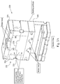
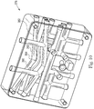
- the mold assembly 328 may include a mold 370 having a first side 372 and a second side 374.
- the first side 372 and the second side 374 form a mold cavity 376 therebetween.
- the first side 372 may be supported by a first mold support plate 378 and the second side 374 may be supported by a second mold support plate 380.
- the first and second mold support plates 378, 380 may be attached to a press (not shown), which actuates to move the first and second sides 372, 374 during the molding process.
- One or more cooling lines 382 may be formed in one or more of the mold support plates 378, 380. Because the first and second sides 372, 374 are made from a highly thermally conductive material, heat flows through the first and second sides 372, 374 to the mold support plates 378, 380 at a rate that is sufficient to cool plastic in the mold cavity 376 in an acceptable amount of time.
- the mold support plates 378, 380 may include posts or other projections 381 that extend outward, away from the mold support plate 378, 380, towards the mold 370.
- the cooling lines 382 may extend into the projections 381.
- the mold 370 may include a complementary feature so that the mold may fit around ( Fig. 5B ), within ( Fig. 5C ), or upon ( Figs. 5D and 5E ) the projections 381. In this way, the cooling lines 382 may be located closer to the mold cavity without extending the cooling lines 382 into the mold 370 or into the first and second mold sides 372, 374.
- the mold support plates 378, 380 may receive molds having a variety of different mold cavity shapes. The molds may thus be formed without cooling lines integrated into the first and/or second sides 372, 374, which reduces manufacturing costs of the molds 370.
- Cooling complexity level one mold assemblies are defined as containing all active cooling lines 382 within the mold support plates 378, 380, even if more than one machining axis is needed to form the cooling lines 382.
- the mold may be a stack mold, a cube mold, a shuttle mold, a helicopter mold, a mold having rotating platens, or other multi-cavity molds to increase productivity if desired.
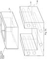
- the cooling complexity level two mold assembly 328 is identical to the cooling complexity level one mold assembly 328 of Figs. 5A-5E , with the exception that the cooling lines 382 in the embodiment of Fig. 6 extend through at least one mold support plate 378, 380 and into at least one mold side 372, 374 (i.e., as opposed to the cooling lines 382 only extending through the mold support plates 378, 380).
- the cooling lines 382 have terminal ends 384. However, each cooling line 382 is machined along an axis that is parallel to a single machining axis.
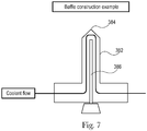
- the cooling lines 382 may include a baffle 386, as shown in more detail in Fig.
- Cooling complexity level two mold assemblies have not been used in high output consumer product injection molding machines (i.e., class 101-102 injection molding machines) because cooling complexity level two mold assemblies do not have enough flexibility to machine cooling lines close to the mold surfaces of the mold cavity and therefore, cooling complexity level two mold assemblies do not provide adequate cooling for conventional high output mold assemblies having high hardness, low thermal conductivity molds.
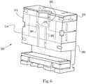
- a cooling complexity level three mold assembly 328 is defined by cooling channels 382 having at least two different machining axes. At least one cooling line 382 may include two different machining axes and a terminal end. More particularly, the cooling line 382 may have a bend or turn. For example, the cooling line 382 may include a first machining axis that is substantially parallel to the opening-closing stroke S of the mold assembly 328 and a second machining axis that is angled with respect to the first machining axis.
- cooling complexity level three mold assemblies have not been used in high output consumer product injection molding machines (e.g., class 101-102 injection molding machines) because level three cooling complexity does not have enough flexibility to machine cooling lines close to the mold surfaces of the mold cavity and therefore, cooling complexity level three mold assemblies do not provide adequate cooling for conventional high output mold assemblies having high hardness, low thermal conductivity molds.
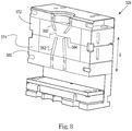
- the cooling complexity level four mold assembly 328 includes a plurality of cooling lines 382, a first cooling line 382a having a terminal end 384 and a second cooling line 382b being a through-bore without a terminal end.
- the first cooling line 382a extends from the mold support plate 378 into the first mold side 372 and the second cooling line 382b extends through the first mold side 372.
- a machining axis for the first cooling line 382a is different from a machining axis for the second cooling line 382b.
- the cooling lines 382 have at least two different machining axes for formation. Cooling complexity level four mold assemblies have been used in some high output consumer product injection molding machines (e.g., class 101-102 injection molding machines) having mold assemblies with very simple mold cavity geometries.
- the cooling complexity level five mold assembly 328 includes a first cooling line 382 that is a through-bore having two different machining axes. As illustrated in Fig. 10 , the first cooling line 382 includes a first section 390 and a second section 392 that are angled with respect to one another and meet at a junction or turn 394. Machining the first cooling line 382 with two different axes that must meet at an internal location in the mold part requires great precision and thus more costly equipment, along with a greater manufacturing time.
- cooling complexity level five mold assemblies 328 have been used in high output consumer product injection molding machines (e.g., class 101-102 injection molding machines) because cooling complexity level five mold assemblies allow for greater customization in cooling line placement.
- cooling lines can be placed closer to the mold cavity than in cooling complexity mold assemblies of lesser complexity.
- the more complex cooling complexity mold assembly can at least partially offset the drawback of lower thermal conductivity found in conventional injection molds made of high hardness, low thermal conductivity materials.
- the cooling complexity level six mold assembly 328 is a cooling complexity level one to five mold assembly that also includes at least one actively cooled dynamic molding part 398. Forming cooling channels in a dynamic molding part 398 requires great precision. Moreover, actively cooled dynamic molding parts 398 require complicated flow mechanisms that move with the dynamic molding part 398 during operation of the mold assembly 328. Cooling complexity level six mold assemblies have been used in high output consumer product injection molding machines (e.g., class 101-102 injection molding machines).
- the cooling complexity level seven mold assembly 328 is a cooling complexity level two through six mold assembly that includes at least one conformal cooling cavity 399.
- the conformal cooling cavity 399 at least partially complements the contours of the mold cavity to provide maximum active cooling.
- the conformal cooling cavity 399 is non-linear, non-coaxial, and/or non-planar. Conformal cooling cavities 399 require complex machinery to form. Additionally, conformal cooling cavities 399 take significant amounts of time to form. As a result, cooling complexity level seven mold assemblies are very expensive and are generally reserved for high output consumer product injection molding machines that have very intricate part geometries.
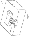
- the simplified cooling systems described herein may be incorporated into virtually any type of conventional injection mold, such as an injection molding machine having a cube mold assembly 428, as illustrated in FIG. 13 .
- a level one cooling complexity level injection mold assembly includes an evaporative cooling system.
- Evaporative cooling systems are more efficient in removing heat than liquid based cooling systems.
- evaporative cooling systems may be 100 times more efficient, or even 500 times more efficient, at removing heat than liquid based cooling systems.
- the injection mold assemblies described herein are made of materials having high thermal conductivity, these mold assemblies may include more simplified cooling systems (by moving cooling lines farther away from the mold cavity) while increasing heat removal by including evaporative cooling systems. Moving cooling lines away from the mold cavity produces more uniform temperature distributions throughout the mold sides.
- level one cooling complexity mold assemblies having evaporative cooling systems do not need complex dynamic seals between the mold support plates and the mold sides because the cooling fluid lines do not extend into the mold sides.
- the evaporative cooling systems in level one cooling complexity level mold assemblies are more robust and less prone to failure than evaporative cooling systems in prior art mold assemblies that required the cooling fluid to extend into the mold sides.
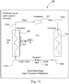
- evaporative cooling systems exploit a phase change in a cooling fluid to extract more heat from the mold assembly than a conventional all liquid cooling system could extract.
- the circulating fluid alternates between a liquid and a gas phase. Transition from a liquid to a gas phase is highly endothermic.
- the liquid cooling fluid passes through a region of elevated temperature (such as the mold support plate, or an evaporator)
- the cooling fluid absorbs heat from the mold support plate and changes phase to a gas.
- the gas then passes to a region of lower temperature, such as a condenser, where heat is transferred from the gas to the environment.
- Evaporative cooling systems may be ten times more effective, 100 times, or even 500 times more effective at removing heat than conventional all liquid cooling systems.
- the elevated temperature cooling fluid enters a heat exchanger or condenser 516.
- the elevated temperature cooling fluid exchanges heat with the atmosphere (or other medium), and the cooling fluid cools below its evaporation temperature, thus condensing into liquid form.
- a mold support plate may comprise the evaporator 522.
- the mold support plate may include one or more cooling channels for moving cooling fluid through the mold support plate to remove heat from the mold support plate.
- the evaporator surfaces are relatively warm, compared to the cooling fluid in the evaporator 522. Thus, heat is transferred from the evaporator (e.g., the mold support plate) to the cooling fluid, which results in vaporization of a majority of the remaining cooling fluid.
- the cooling fluid moves through cooling line 512d to the compressor 510 and the process is repeated.
- the evaporator 522, the compressor 510, the condenser 516, and the expansion valve 520 are all fluidly connected to one another by the cooling lines 512a-d.
- the entire cooling circuit 514 may be located within or on the evaporator 522 or mold support plate.
- the mold support plate may comprise the evaporator 522 (having one or more cooling channels located within the mold support plate), while one or more of the compressor 510, the condenser 516, and the expansion valve 520 may be physically separated from the mold support plate, while being fluidly connected to the mold support plate via the cooling lines 512a-d.
- Fig. 15 illustrates one embodiment of an evaporative cooling system 600 that may be used in an injection molding machine.
- the evaporative cooling system 600 includes the same elements as the evaporative cooling system of Fig. 14 , with respective elements having reference numerals increased by 100.
- the evaporative cooling system 600 includes a compressor 610, a condenser 616, an expansion valve 620 and an injection mold 622, all fluidly connected by a plurality of cooling lines 612a-d to form a closed loop cooling circuit 614.
- the injection mold 622 itself, and more specifically a mold support plate of the injection mold 622, forms the evaporator.
- Cooling fluid flowing through the injection mold 622 removes heat from the injection mold 622, thereby cooling molten plastic within the injection mold 622.
- the increased cooling capacity of the evaporative cooling system 600 reduces cycle time of the injection mold 622 by removing heat more quickly than traditional cooling systems that move cooling liquid only through cooling channels.
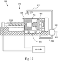
- evaporative cooling system 700 which is located in a mold support plate 478 of an injection mold, is illustrated.
- the evaporative cooling system 700 includes a chamber 710 within the mold support plate 478.
- An evaporative liquid 712 such as water, is disposed within the chamber 710.
- a percolator tube 714 connects a reservoir portion 716 of the chamber 710 to a condensing portion 718 of the chamber 710.
- the percolator tube 714 assists in moving water from the bottom of the chamber 710 to the top of the chamber 710.
- a cooled condenser 720 may be located near the top of the chamber 710. As heat from the mold side (which would be located to the right in Fig.
- a coating may be applied to the side walls that enhances retention of liquid water against the side walls by increasing surface tension between the liquid water and the side walls.
- a controllable heat source 722 may optionally be disposed within the mold support plate 478 (or be attached to the mold support plate 478) to regulate the volume of water returned to the condensing section 718 through the percolator tube 714.
- FIG. 16B illustrates an alternate embodiment of an evaporative cooling system 800.
- Elements of the evaporative cooling system 800 like those of the evaporative cooling system 700 of FIG. 16A have reference numerals that are 100 greater than the elements in FIG. 16A .
- the main difference in the evaporative cooling system 800 of FIG. 16B is that an additional collection portion 830 is located within the chamber 810 vertically between the condensing portion 818 and the reservoir portion 816.
- the collection portion 830 may facilitate collection and re-evaporation of liquid water for larger (or longer) mold support plates.
- the evaporative (and vapor compression) cooling systems 500, 600, 700, and 800 of FIGS. 14 , 15 , 16A , and 16B may include a vacuum system to lower relative pressures of the cooling fluids. Lowering relative pressures of the cooling fluids lowers the evaporation temperature for a given cooling fluid (all other factors being equal).
- the evaporative (and vapor compression) cooling systems 500, 600, 700, and 800 may include a pressurization system to increase relative pressure of the cooling fluid. Raising relative pressure of the cooling fluid raises the evaporation temperature of a given cooling fluid (all other factors being equal). In this way, the evaporation temperature may be tailored to the temperatures typically experienced by a particular mold.
- Evaporative cooling systems may use many different types of cooling fluids, such as refrigerants (e.g., chlorofluorocarbons, chlorofluoroolefins, hydrochlorofluorocarbons, hydrochlorofluoroolefins, hydrofluorocarbons, hydrofluoroolefins, hydrochlorocarbons, hydrochloroolefins, hydrocarbons, hydroolefins, perfluorocarbons, perfluoroolefins, perchlorocarbons, perchloroolefins, and halon/haloalkane, and blends thereof), water, glycol, propylene glycol, alcohol, or mercury.
- refrigerants e.g., chlorofluorocarbons, chlorofluoroolefins, hydrochlorofluorocarbons, hydrochlorofluoroolefins, hydrofluorocarbons, hydrofluoroolefins, hydrochlor
- refrigerants having cooling capacities and/or physical or chemical properties similar to the refrigerants listed above may also be used.
- a surfactant may be added to the cooling fluid.
- Some evaporative cooling systems may utilize a vacuum system to create differential pressure, while other evaporative cooling systems may utilize compressors to create differential pressure.
- the evaporative cooling system may employ atmospheric liquid evaporation to remove heat. Because the disclosed mold assemblies are made of highly thermally conductive materials, in some cooling complexity level zero mold assemblies it is possible to simply spray a cooling liquid on the outer surface of the mold support plates or mold sides, which evaporates as the liquid absorbs heat, thereby cooling the mold support plate or the mold side.
- a cooling liquid that may be advantageously employed in these types of systems is distilled water. Distilled water will completely evaporate without leaving any type of residue on the mold support plate or mold side.
- fins or radiator structures may be used to increase surface area of the mold support plate or mold side to further facilitate evaporation and heat removal.
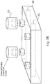
- the mold 910 may include a first mold side 925 and a second mold side 927.
- a first mold support plate 978 and a second mold support plate 980 may be located adjacent the first and second mold sides 925, 927, respectively.
- a spray bar 911 may be positioned near one of the mold support plates 978, 980, and/or near one of the mold sides 925, 927.
- the spray bar 910 is fluidly connected to a pump 912, which pumps liquid (for example water) to the spray bar 910 under pressure.
- the liquid is sprayed out of a nozzle 914 so that the sprayed liquid coats an outer surface of one of the mold support plates 978, 980 and the mold sides 925, 927.
- heat from the mold support plate 978, 980, and/or the mold side 925, 927 causes the liquid to evaporate, thus cooling the mold support plate 978, 980 and/or the mold side 927, 927.
- Liquid that does not evaporate may drip down and collect in a liquid collection area or sump 940.
- the sump 940 is an area or reservoir for collecting liquid that does not evaporate.
- a return line 942 extends from the sump 940 to the pump 912 to channel water from the sump 940 back to the spray bar 911.
- the pump 912 may also be connected to a source of liquid 944 so that a supply of liquid is always available to the spray bar 911, regardless of the level of liquid in the sump 940.
- evaporated liquid simply vents to the atmosphere and fresh liquid is supplied through the source of liquid 944 to make up for the lost evaporated liquid.
- the entire mold 910 may be located in a closed environment and the evaporated liquid may be condensed and returned to the sump 940.
- the disclosed mold assemblies may include cooling systems having cooling channels that are completely confined within a mold support plate. As a result, the disclosed systems do not need any dynamic seals (e.g., seals between moving parts) and the risk of cooling fluid escaping to the atmosphere, or being released into the environment is reduced.
- dynamic seals e.g., seals between moving parts
- the cooling systems disclosed herein for a level one cooling complexity mold, include cooling channels only in one or more of the mold support plates. In other words, there are no cooling channels in either the first mold side or the second mold side. As a result, all seals in the cooling systems are static in nature and very robust. Stated another way, there are no seals between components that move relative to one another in the disclosed cooling systems, which would require softer, dynamic seals. Thus, the disclosed cooling systems may use dangerous, hazardous, or expensive cooling fluids (sometimes referred to as "exotic cooling fluids”) as there is little chance of seal breach, which would result in release of the cooling fluid. Some dangerous, hazardous, or expensive cooling fluids may have superior heat absorption properties when compared to traditional cooling fluids.
- cooling fluids have not been previously used in cooling systems for injection molds for fear of seal breach (especially a breach in dynamic seals between moving parts), which would release these cooling fluids to the atmosphere.
- Particularly useful dangerous, hazardous, or expensive cooling fluids that may now be used in the disclosed cooling systems (due to the very low risk of these cooling fluids escaping to the atmosphere) include heating oil, hydraulic fluid, glycols, cesium, mercury, potassium (which has a thermal conductivity of approximately 42 W/mK at 25°C), lead-bismuth eutectic, sodium potassium alloy, sodium potassium cesium alloy, and lead-bismuth.
- Desirable cooling fluids may have a thermal conductivity of 1 W/mK or more. More desirable cooling fluids may have a thermal conductivity of between about 1 W/mk to about 42 W/mk. Some desirable cooling liquids maintain a flowable viscosity (e.g., a cpi of 100,000 or less) at temperatures between about 5°C and about 100°C.
- non-hazardous cooling fluids that are relatively expensive may also be used in the disclosed cooling systems.
- One such expensive, but useful, cooling fluid is distilled water, which advantageously dose not corrode internal components of the disclosed cooling systems. Distilled water, however, has not been used in conventional high productivity injection molding systems because of the need to constantly replace distilled water lost through seal breaches. These losses generally required a distillation plant on site to produce make up distilled water, which is cost prohibitive in the highly competitive consumer products injection molding industry.
- Nanofluids may be used as cooling fluids.
- Nanofluids include a carrier liquid, such as water, having tiny nano-scale particles known as nanoparticles dispersed throughout the carrier liquid.
- Nanoparticles of solid materials e.g., copper oxide, alumina, titanium dioxide, carbon nanotubes, silica, or metals, including copper, or silver nanorods
- the enhancement can be theoretically as high as 350%.
- nanofluids have been experimentally shown to have thermal conductivities of 50%-100% greater than the thermal conductivity of the carrier liquid alone. Nanofluids also exhibit a significant increase in heat flux when compared to traditional cooling fluids.
- a nanofluid may comprise ethylene glycol and copper nanoparticles, which has a thermal conductivity of approximately 1.4 W/mK at 25°C.
- silver nanorods of 55 ⁇ 12 nm diameter and 12.8 ⁇ m average length at 0.5 viol.% can increase thermal conductivity of water by 68%, and 0.5 vol.% of silver nanorods increased thermal conductivity of ethylene glycol based coolant by 98%.
- Alumina nanoparticles at 0.1% can increase the critical heat flux of water by as much as 70%.
- the disclosed cooling complexity level one molds may use nanofluids to increase heat transfer rates, which results in more efficient cooling.
- Desirable nanofluids may have thermal conductivities of 1 W/mK or more. Examples of nanoparticles that may be added to a carrier fluid include copper oxide, alumina, titanium oxide, boron nitride nanotubes, carbon nanotubes, carbon uranium nano rods, and silver nano rods.
- these nanofluids have a greater heat capacity than traditional cooling fluids.
- fluid circulation rates may be slowed to allow the nanofluid to remove more heat per unit volume than traditional cooling fluids.
- the overall cooling fluid volume needed for such a system may be reduced, causing a corresponding reduction in overall cost and complexity of the cooling system.
- This increase in thermal conductivity and reduction in overall fluid volume may allow some cooling complexity level one molds that use nanofluids to employ a radiant heat type heat exchanger to cool the nanofluid before circulation through the mold support plate, as the nanofluid would linger in the heat exchanger long enough to adequately cool the nanofluid.
- the mold may be cooled completely by convection/conduction of heat to the atmosphere.
- Radiator fins may be formed on the mold support plates or the mold sides to enhance convection of heat to the atmosphere.
- a gas moving device such as a fan, may move atmospheric gases over the molds and/or over the radiator fins to further enhance heat dissipation though conduction.
- the low constant pressure injection molding machines include mold assemblies manufactured from materials having high thermal conductivity, in accordance with the current invention.
- This high thermal conductivity allows the disclosed mold assemblies to cool molded parts using cooling complexity level three mold assemblies or lower for virtually any part geometry.
- a cooling complexity level two mold assembly will be used to cool a molded part.
- a cooling complexity level one mold assembly will be used to cool a molded part.
- a cooling complexity level zero mold assembly may even be used.
- the cooling complexity level three or lower mold assemblies may be used even in ultra high output consumer product injection molding machines (e.g., class 101-102 injection molding machines) where more complex cooling systems were needed for conventional injection molds made from high hardness, low thermal conductivity materials.
- the disclosed low constant pressure injection mold assemblies, and thus the injection molding machines are less costly to manufacture, while decreasing mold cycle times and increasing mold productivity due at least in part to the availability of less complex cooling systems.
- molds made from high thermal conductivity materials are more uniform during the injection molding process than in conventional molds. In other words, there is less temperature variation from point to point within the mold.
- parts manufactured in molds with high thermal conductivity have less internal stress (and a more uniform crystalline structure) than parts manufactured in conventional molds. This lower internal stress and more uniform crystallinity result in lower rates of part warp.
- the mold cavity is often designed to offset part warp due to nonuniform temperature gradients, which adds to the cost and complexity of conventional mold assemblies. Finalizing a particular offset usually requires an iterative and time consuming trial process.
- the mold cavity need not be designed to offset warp because the molded part does not experience a significant amount of warp, as internal stresses are more uniform due to the more uniform cooling.
- the iterative offset process used in the design of conventional molds may be avoided, further reducing manufacturing costs and time.
- the terms “substantially,” “about,” and “approximately,” unless otherwise specified, may be utilized herein to represent the inherent degree of uncertainty that may be attributed to any quantitative comparison, value, measurement, or other representation. These terms are also utilized herein to represent the degree by which a quantitative representation may vary from a stated reference without resulting in a change in the basic function of the subject matter at issue. Unless otherwise defined herein, the terms “substantially,” “about,” and “approximately” mean the quantitative comparison, value, measurement, or other representation may fall within 20% of the stated reference.
Landscapes
- Engineering & Computer Science (AREA)
- Mechanical Engineering (AREA)
- Manufacturing & Machinery (AREA)
- Physics & Mathematics (AREA)
- Fluid Mechanics (AREA)
- Health & Medical Sciences (AREA)
- Oral & Maxillofacial Surgery (AREA)
- Thermal Sciences (AREA)
- Moulds For Moulding Plastics Or The Like (AREA)
- Injection Moulding Of Plastics Or The Like (AREA)
Applications Claiming Priority (4)
| Application Number | Priority Date | Filing Date | Title |
|---|---|---|---|
| US201261641349P | 2012-05-02 | 2012-05-02 | |
| US13/601,359 US20130295219A1 (en) | 2012-05-02 | 2012-08-31 | Injection Mold Having a Simplified Evaporative Cooling System or a Simplified Cooling System with Exotic Cooling Fluids |
| US13/765,428 US8591219B1 (en) | 2012-05-02 | 2013-02-12 | Injection mold having a simplified evaporative cooling system |
| PCT/US2013/039243 WO2013166272A2 (en) | 2012-05-02 | 2013-05-02 | Injection mold having a simplified evaporative cooling system or a simplified cooling system with exotic cooling fluids |
Publications (2)
| Publication Number | Publication Date |
|---|---|
| EP2844453A2 EP2844453A2 (en) | 2015-03-11 |
| EP2844453B1 true EP2844453B1 (en) | 2017-09-27 |
Family
ID=49512707
Family Applications (1)
| Application Number | Title | Priority Date | Filing Date |
|---|---|---|---|
| EP13723615.4A Active EP2844453B1 (en) | 2012-05-02 | 2013-05-02 | Injection mold having a simplified evaporative cooling system or a simplified cooling system with exotic cooling fluids |
Country Status (13)
| Country | Link |
|---|---|
| US (3) | US20130295219A1 (enExample) |
| EP (1) | EP2844453B1 (enExample) |
| JP (1) | JP5973656B2 (enExample) |
| CN (1) | CN104271329A (enExample) |
| AU (1) | AU2013256204A1 (enExample) |
| BR (1) | BR112014027424A2 (enExample) |
| CA (1) | CA2871980C (enExample) |
| IN (1) | IN2014DN08887A (enExample) |
| MX (1) | MX2014012871A (enExample) |
| PH (1) | PH12014502433B1 (enExample) |
| RU (1) | RU2014142162A (enExample) |
| TW (1) | TW201406522A (enExample) |
| WO (1) | WO2013166272A2 (enExample) |
Families Citing this family (30)
| Publication number | Priority date | Publication date | Assignee | Title |
|---|---|---|---|---|
| US20190118442A9 (en) * | 2010-04-20 | 2019-04-25 | Honda Motor Co., Ltd. | Conforming cooling method and mold |
| CN103097104A (zh) * | 2010-09-23 | 2013-05-08 | 赫斯基注塑系统有限公司 | 包括用于歧管组件的恒温加热器组件的模具组件 |
| CA2913161C (en) | 2011-05-20 | 2017-11-14 | Gene Michael Altonen | Method and apparatus for substantially constant pressure injection molding of thinwall parts |
| CN103547427A (zh) | 2011-05-20 | 2014-01-29 | 宝洁公司 | 用于注塑设备的非自然平衡的进料系统 |
| CN103547430A (zh) | 2011-05-20 | 2014-01-29 | 宝洁公司 | 用于在低恒定压力下注塑的设备和方法 |
| PH12013502388A1 (en) | 2011-05-20 | 2014-01-27 | Imflux Inc | Method for injection molding at low, substantially constant pressure |
| BR112013029694A2 (pt) | 2011-05-20 | 2017-01-17 | Procter & Gamble | controle de pressão alternativo para um aparelho de moldagem por injeção a pressão constante baixa |
| WO2013126723A1 (en) | 2012-02-24 | 2013-08-29 | The Procter & Gamble Company | Injection mold having a simplified cooling system |
| US20130295219A1 (en) * | 2012-05-02 | 2013-11-07 | Ralph Edwin Neufarth | Injection Mold Having a Simplified Evaporative Cooling System or a Simplified Cooling System with Exotic Cooling Fluids |
| US9339952B2 (en) * | 2012-06-20 | 2016-05-17 | Magna International, Inc. | Nanofluid mold cooling |
| US9604398B2 (en) | 2012-11-08 | 2017-03-28 | Imflux Inc | Injection mold with fail safe pressure mechanism |
| EP2922680A2 (en) | 2012-11-21 | 2015-09-30 | iMFLUX Inc. | Reduced size runner for an injection mold system |
| JP5726845B2 (ja) * | 2012-12-13 | 2015-06-03 | 本田技研工業株式会社 | 鋳造金型冷却装置及び鋳造金型冷却方法 |
| CN105555439B (zh) * | 2013-04-15 | 2019-02-19 | 麦格纳国际公司 | 具有散热装置的液冷式压铸模具 |
| RU2015145440A (ru) | 2013-05-13 | 2017-06-19 | Дзе Проктер Энд Гэмбл Компани | Система инжекционного формования с низким постоянным давлением, с изменяемым положением полостей пресс-формы |
| BR112016002262A2 (pt) | 2013-08-01 | 2017-08-29 | Imflux Inc | Máquinas de moldagem por injeção e métodos para realizar alterações nas propriedades do material durante operações de moldagem por injeção |
| JP6144840B2 (ja) | 2013-08-01 | 2017-06-07 | アイエムフラックス インコーポレイテッド | 射出成形運転中の材料特性の変化を考慮する射出成形機及び方法 |
| US9216532B2 (en) * | 2014-02-14 | 2015-12-22 | GM Global Technology Operations LLC | Injection mold assembly |
| CA2968089C (en) | 2014-12-22 | 2020-07-07 | The Procter & Gamble Company | Package for consumer care products |
| EP3236798A1 (en) | 2014-12-22 | 2017-11-01 | The Procter and Gamble Company | Package for consumer care products |
| MX380640B (es) | 2014-12-22 | 2025-03-11 | Procter & Gamble | Envase para productos para el cuidado del consumidor. |
| US20160229001A1 (en) * | 2015-02-05 | 2016-08-11 | GM Global Technology Operations LLC | Thermal-management systems for controlling temperature of workpieces being joined by welding |
| DE102016203995A1 (de) * | 2016-03-10 | 2017-09-14 | Otto Männer Innovation GmbH | Heißkanalsystem und damit verbundene Düsenheizeinrichtungen |
| CN107658276B (zh) * | 2017-08-23 | 2019-07-02 | 安徽工程大学 | 一种用于微电子芯片表面的散热结构 |
| JP7221066B2 (ja) * | 2019-01-31 | 2023-02-13 | 住友重機械工業株式会社 | 射出成形機用冷却装置及び成形品取出システム |
| WO2021076720A1 (en) * | 2019-10-15 | 2021-04-22 | Dme Company Llc | Mold plate cooling arrangement |
| JP7581622B2 (ja) | 2020-01-28 | 2024-11-13 | セイコーエプソン株式会社 | 射出成形装置、射出成形装置用冷却プレート、および、カセット型 |
| CN111590809B (zh) * | 2020-05-23 | 2022-11-08 | 芜湖达锦新材料科技有限公司 | 一种可调节式多功能发泡模具装置 |
| CN113276369A (zh) * | 2021-07-12 | 2021-08-20 | 深圳市鸿运沅电子有限公司 | 一种耳机壳体注塑模具及其注塑工艺 |
| CN114603802B (zh) * | 2022-04-15 | 2025-01-24 | 深圳市鸿兴达塑胶制品有限公司 | 一种温控型注塑模具及注塑方法 |
Family Cites Families (81)
| Publication number | Priority date | Publication date | Assignee | Title |
|---|---|---|---|---|
| US2350348A (en) | 1942-12-21 | 1944-06-06 | Gen Motors Corp | Heat transfer device |
| US3127753A (en) | 1960-01-04 | 1964-04-07 | George A Tinnerman | Method of chilling die elements of molding apparatus |
| DE2427969A1 (de) | 1974-06-10 | 1976-01-02 | Reinhard Colortronic | Verfahren und vorrichtung zum spritzgiessen, insbesondere von kunststoffen |
| US4219322A (en) | 1978-12-20 | 1980-08-26 | Owens-Illinois, Inc. | Apparatus for molding plastic articles |
| JPS60127125A (ja) | 1983-12-14 | 1985-07-06 | Chisso Corp | 射出成形方法 |
| GB8424357D0 (en) | 1984-09-26 | 1984-10-31 | British Telecomm | Injection moulding apparatus |
| JPH0222026A (ja) * | 1988-01-04 | 1990-03-28 | Toshiba Corp | ディスク成形用金型 |
| DE3836875A1 (de) * | 1988-04-07 | 1989-10-26 | Erlenbach Gmbh & Co Kg | Verfahren und vorrichtung zum herstellen von formlingen aus expandierbaren kunststoffpartikeln |
| JP2691581B2 (ja) | 1988-10-03 | 1997-12-17 | 東芝機械株式会社 | 射出成形装置およびこれを用いる射出成形方法 |
| JPH0379317A (ja) | 1989-08-23 | 1991-04-04 | Toshiba Corp | プラスチックの成形品 |
| US5478520A (en) | 1989-10-27 | 1995-12-26 | Mitsubishi Jukogyo Kabushiki Kaisha | Process for injection molding and apparatus therefor |
| JPH04126214A (ja) | 1990-09-17 | 1992-04-27 | Fuji Photo Film Co Ltd | 金型 |
| US5260014A (en) * | 1991-06-13 | 1993-11-09 | Automotive Plastic Technologies | Method of making a multilayer injection mold |
| JPH056914A (ja) | 1991-06-27 | 1993-01-14 | Fujitsu Ltd | 半導体装置の樹脂封止装置およびその樹脂封止方法 |
| JPH0577244A (ja) | 1991-09-19 | 1993-03-30 | Sony Corp | 金 型 |
| CA2079390C (en) | 1991-10-16 | 1996-08-27 | Akira Nonomura | Multi-cavity mold, method of fabricating same and molding control method using said mold |
| JPH0753405B2 (ja) | 1991-11-28 | 1995-06-07 | 花王株式会社 | 射出成形機における樹脂流動物性変動制御方法および装置 |
| JP2559651B2 (ja) | 1991-12-26 | 1996-12-04 | 花王株式会社 | 射出成形の制御方法および装置 |
| US6276656B1 (en) | 1992-07-14 | 2001-08-21 | Thermal Wave Molding Corp. | Mold for optimizing cooling time to form molded article |
| JPH072359B2 (ja) | 1992-10-22 | 1995-01-18 | 大宝工業株式会社 | 射出成形ユニット |
| US5775402A (en) * | 1995-10-31 | 1998-07-07 | Massachusetts Institute Of Technology | Enhancement of thermal properties of tooling made by solid free form fabrication techniques |
| US5407342A (en) | 1993-09-13 | 1995-04-18 | Boucher; Paul Y. | Apparatus for manufacturing a composite product |
| JPH07223242A (ja) | 1994-02-15 | 1995-08-22 | Mitsubishi Materials Corp | 複数個取り金型 |
| US5716561A (en) | 1994-05-02 | 1998-02-10 | Guergov; Milko G. | Injection control system |
| US5441680B1 (en) | 1994-05-02 | 1997-04-29 | Milko G Guergov | Method and apparatus for injection molding |
| JPH08200915A (ja) * | 1995-01-30 | 1996-08-09 | Ikegami Kanagata Kogyo Kk | 冷却装置 |
| US5811494A (en) | 1995-04-06 | 1998-09-22 | The Dow Chemical Company | Impact modified thinwall polymer compositions |
| EP0749821B1 (en) | 1995-06-19 | 2003-03-05 | Siebolt Hettinga | A low pressure method for injection molding a plastic article |
| US5902525A (en) | 1995-06-19 | 1999-05-11 | Hettinga; Siebolt | Method of molding a plastic article including injecting based upon a pressure-dominated control algorithm after detecting an indicia of a decrease in the surface area of the melt front |
| US5939004A (en) * | 1995-11-30 | 1999-08-17 | Harrison; Donald G. | Molding thermosetting polymers onto substrates |
| US6464909B1 (en) | 1998-04-21 | 2002-10-15 | Synventive Molding Solutions, Inc. | Manifold system having flow control |
| CH692383A5 (de) | 1997-09-16 | 2002-05-31 | Kk Holding Ag | Verfahren zur Regelung der Heisskanalheizung eines Mehrkavitäten-Spritzgiesswerkzeugs. |
| AU2496699A (en) * | 1998-02-06 | 1999-08-23 | Express Tool, Inc. | Thermally efficient mold apparatus and method |
| JPH11262936A (ja) | 1998-03-18 | 1999-09-28 | Sekisui Chem Co Ltd | 硬質塩化ビニル樹脂の射出成形方法 |
| US6824379B2 (en) | 1998-04-21 | 2004-11-30 | Synventive Molding Solutions, Inc. | Apparatus for utilizing an actuator for flow control valve gates |
| AUPP403398A0 (en) | 1998-06-11 | 1998-07-02 | James, Malcolm Barry | Temperature control method and apparatus |
| JP2000202863A (ja) * | 1999-01-11 | 2000-07-25 | Sekisui Chem Co Ltd | 射出成形用金型 |
| JP4081201B2 (ja) | 1999-03-29 | 2008-04-23 | 本田技研工業株式会社 | タンデム型射出成形装置およびそれを使用する成形品の製造方法 |
| US6290882B1 (en) * | 1999-06-07 | 2001-09-18 | Galic Maus Ventures Llp | Reduced-knitline thermoplastic injection molding using multi-gated non-sequential-fill method and apparatus, with a heating phase and a cooling phase in each molding cycle |
| JP2001009836A (ja) * | 1999-06-29 | 2001-01-16 | Inoac Corp | プラスチック成形用金型 |
| US6372162B1 (en) | 1999-08-31 | 2002-04-16 | The Gillette Company | Injection molding of oral brush bodies |
| US6719942B1 (en) * | 1999-09-08 | 2004-04-13 | David A. Triplett | Method and apparatus for production of tubing |
| AUPQ307799A0 (en) | 1999-09-24 | 1999-10-21 | Ritemp Pty Ltd | Improvements relating to cooling of dies |
| US6616871B1 (en) | 1999-11-05 | 2003-09-09 | Toshiba Kikai Kabushiki Kaisha | Filling step control method of injection molding machine |
| JP3625166B2 (ja) | 1999-12-20 | 2005-03-02 | 矢崎総業株式会社 | 成形仮係止金型及び成形仮係止方法 |
| JP2002283355A (ja) * | 2001-03-28 | 2002-10-03 | Toray Ind Inc | 樹脂成形金型 |
| JP3636101B2 (ja) * | 2001-06-22 | 2005-04-06 | 三菱電機株式会社 | 金型装置 |
| DE10256036A1 (de) * | 2002-11-30 | 2004-06-17 | Messer Griesheim Gmbh | Verfahren und Vorrichtung zur Werkzeugkühlung |
| ATE347476T1 (de) * | 2003-01-24 | 2006-12-15 | Almar Packaging Solutions Pty | Rotationsformmaschine |
| MXPA05010511A (es) * | 2003-03-31 | 2005-11-16 | Nissha Printing | Molde para decoracion en molde. |
| US7168942B1 (en) * | 2003-07-31 | 2007-01-30 | Cito Products, Inc. | Method and apparatus for mold temperature control using air |
| JP2005215497A (ja) | 2004-01-30 | 2005-08-11 | Nippon Zeon Co Ltd | 光拡散板及びその製造方法 |
| US8108982B2 (en) * | 2005-01-18 | 2012-02-07 | Floodcooling Technologies, L.L.C. | Compound mold tooling for controlled heat transfer |
| US8501060B2 (en) * | 2005-02-14 | 2013-08-06 | Moldcool International Llc | Method and apparatus for controlling the temperature of molds, dies, and injection barrels using fluid media |
| DE202005020533U1 (de) | 2005-05-12 | 2006-03-16 | Stemke, Gudrun | Kühlsystem für Werkzeuge von Kunststoffverarbeitungsmaschinen |
| US7621739B2 (en) * | 2005-07-25 | 2009-11-24 | Isothermal Systems Research, Inc. | Injection molding apparatus for producing an atomizer |
| WO2007027606A1 (en) * | 2005-08-30 | 2007-03-08 | Advanced Plastics Technologies Luxembourg S.A. | Methods and systems for controlling mold temperatures |
| US20080064805A1 (en) | 2005-10-07 | 2008-03-13 | Mitsui Chemicals, Inc. | Process for producing injection molded product |
| US7794643B2 (en) * | 2006-03-24 | 2010-09-14 | Ricoh Company, Ltd. | Apparatus and method for molding object with enhanced transferability of transfer face and object made by the same |
| ATE508854T1 (de) * | 2006-11-21 | 2011-05-15 | Thermal Cyclic Technologies Tctech I Stockholm Ab | Spritzgiessform mit induktionsheizung sowie spritzgiessverfahren |
| JP4429304B2 (ja) | 2006-12-19 | 2010-03-10 | 本田技研工業株式会社 | 射出成形方法及び射出成形装置 |
| US20090020924A1 (en) * | 2007-02-21 | 2009-01-22 | Iowa State University Research Foundation, Inc. | Drying-mediated self-assembly of ordered or hierarchically ordered micro- and sub-micro scale structures and their uses as multifunctional materials |
| JP4976888B2 (ja) | 2007-03-06 | 2012-07-18 | ソニー株式会社 | 射出制御装置 |
| DE102008000452A1 (de) * | 2008-02-29 | 2009-09-03 | Stemke, Gudrun | Kühlmittelverteilung zur Werkzeugkühlung |
| KR20090114766A (ko) | 2008-04-30 | 2009-11-04 | 엘지디스플레이 주식회사 | 사출성형 금형, 이를 이용하여 제작된 도광판, 이 도광판을갖는 액정표시장치 |
| JP5092927B2 (ja) | 2008-06-20 | 2012-12-05 | ソニー株式会社 | 射出成形の制御方法及び射出成形の制御装置 |
| CN102361927B (zh) | 2009-03-23 | 2013-10-16 | 巴塞尔聚烯烃意大利有限责任公司 | 聚烯烃母料和适于注射成型的组合物 |
| KR101273629B1 (ko) * | 2009-09-07 | 2013-06-14 | 오형종 | 사출금형 장치 |
| DE102009046835A1 (de) | 2009-11-18 | 2011-05-19 | Robert Bosch Gmbh | Spritzgießwerkzeug |
| CN201693719U (zh) * | 2010-06-23 | 2011-01-05 | 百塑企业股份有限公司 | 具有模具冷却功能的射出成型机 |
| CN102294780A (zh) * | 2010-06-25 | 2011-12-28 | 鸿富锦精密工业(深圳)有限公司 | 注塑系统及注塑方法 |
| BR112013029694A2 (pt) | 2011-05-20 | 2017-01-17 | Procter & Gamble | controle de pressão alternativo para um aparelho de moldagem por injeção a pressão constante baixa |
| CN103547427A (zh) | 2011-05-20 | 2014-01-29 | 宝洁公司 | 用于注塑设备的非自然平衡的进料系统 |
| CN103547430A (zh) | 2011-05-20 | 2014-01-29 | 宝洁公司 | 用于在低恒定压力下注塑的设备和方法 |
| PH12013502388A1 (en) | 2011-05-20 | 2014-01-27 | Imflux Inc | Method for injection molding at low, substantially constant pressure |
| CA2913161C (en) | 2011-05-20 | 2017-11-14 | Gene Michael Altonen | Method and apparatus for substantially constant pressure injection molding of thinwall parts |
| AU2012258954B2 (en) | 2011-05-20 | 2016-03-03 | iMFLUX Inc. | Method for injection molding at low, substantially constant pressure |
| WO2013126723A1 (en) | 2012-02-24 | 2013-08-29 | The Procter & Gamble Company | Injection mold having a simplified cooling system |
| US20130221575A1 (en) | 2012-02-24 | 2013-08-29 | The Procter & Gamble Company | Method for Operating a High Productivity Injection Molding Machine |
| KR20140117601A (ko) | 2012-02-24 | 2014-10-07 | 더 프록터 앤드 갬블 캄파니 | 높은 열전도율의 공사출 성형 시스템 |
| US20130295219A1 (en) | 2012-05-02 | 2013-11-07 | Ralph Edwin Neufarth | Injection Mold Having a Simplified Evaporative Cooling System or a Simplified Cooling System with Exotic Cooling Fluids |
-
2012
- 2012-08-31 US US13/601,359 patent/US20130295219A1/en not_active Abandoned
-
2013
- 2013-02-12 US US13/765,428 patent/US8591219B1/en not_active Expired - Fee Related
- 2013-05-02 CN CN201380022879.3A patent/CN104271329A/zh active Pending
- 2013-05-02 CA CA2871980A patent/CA2871980C/en active Active
- 2013-05-02 MX MX2014012871A patent/MX2014012871A/es not_active Application Discontinuation
- 2013-05-02 BR BR112014027424A patent/BR112014027424A2/pt not_active IP Right Cessation
- 2013-05-02 RU RU2014142162A patent/RU2014142162A/ru not_active Application Discontinuation
- 2013-05-02 TW TW102115796A patent/TW201406522A/zh unknown
- 2013-05-02 AU AU2013256204A patent/AU2013256204A1/en not_active Abandoned
- 2013-05-02 EP EP13723615.4A patent/EP2844453B1/en active Active
- 2013-05-02 JP JP2015510452A patent/JP5973656B2/ja not_active Expired - Fee Related
- 2013-05-02 IN IN8887DEN2014 patent/IN2014DN08887A/en unknown
- 2013-05-02 WO PCT/US2013/039243 patent/WO2013166272A2/en not_active Ceased
-
2014
- 2014-09-19 US US14/491,257 patent/US9682505B2/en active Active
- 2014-10-30 PH PH12014502433A patent/PH12014502433B1/en unknown
Non-Patent Citations (1)
| Title |
|---|
| None * |
Also Published As
| Publication number | Publication date |
|---|---|
| PH12014502433A1 (en) | 2015-01-12 |
| TW201406522A (zh) | 2014-02-16 |
| BR112014027424A2 (pt) | 2017-06-27 |
| US8591219B1 (en) | 2013-11-26 |
| US20130295219A1 (en) | 2013-11-07 |
| US9682505B2 (en) | 2017-06-20 |
| US20130295220A1 (en) | 2013-11-07 |
| CA2871980A1 (en) | 2013-11-07 |
| CA2871980C (en) | 2017-08-29 |
| RU2014142162A (ru) | 2016-05-10 |
| IN2014DN08887A (enExample) | 2015-05-22 |
| US20150064303A1 (en) | 2015-03-05 |
| WO2013166272A2 (en) | 2013-11-07 |
| AU2013256204A1 (en) | 2014-11-13 |
| JP5973656B2 (ja) | 2016-08-23 |
| MX2014012871A (es) | 2015-01-19 |
| JP2015515404A (ja) | 2015-05-28 |
| PH12014502433B1 (en) | 2015-01-12 |
| WO2013166272A3 (en) | 2014-03-06 |
| EP2844453A2 (en) | 2015-03-11 |
| CN104271329A (zh) | 2015-01-07 |
Similar Documents
| Publication | Publication Date | Title |
|---|---|---|
| EP2844453B1 (en) | Injection mold having a simplified evaporative cooling system or a simplified cooling system with exotic cooling fluids | |
| EP2817138B1 (en) | Injection mold having a simplified cooling system | |
| US8757999B2 (en) | Alternative pressure control for a low constant pressure injection molding apparatus | |
| US10076861B2 (en) | Apparatus for injection molding at low constant pressure | |
| EP3344427B1 (en) | 3-d printed mold for injection molding | |
| US20170225361A1 (en) | Heat recovery apparatus and method for molding | |
| US20180162037A1 (en) | Molding device for executing hot-molding and cold-molding methods | |
| KR20140143433A (ko) | 신종 냉각 유체를 갖는 간이화된 냉각 시스템 또는 간이화된 증발 냉각 시스템을 구비한 사출 주형 | |
| EP3582942B1 (en) | Cooling system for moulds | |
| AU2016200940A1 (en) | Alternative pressure control for a low constant pressure injection molding apparatus | |
| AU2012258952A1 (en) | Alternative pressure control for a low constant pressure injection molding apparatus |
Legal Events
| Date | Code | Title | Description |
|---|---|---|---|
| PUAI | Public reference made under article 153(3) epc to a published international application that has entered the european phase |
Free format text: ORIGINAL CODE: 0009012 |
|
| 17P | Request for examination filed |
Effective date: 20141014 |
|
| AK | Designated contracting states |
Kind code of ref document: A2 Designated state(s): AL AT BE BG CH CY CZ DE DK EE ES FI FR GB GR HR HU IE IS IT LI LT LU LV MC MK MT NL NO PL PT RO RS SE SI SK SM TR |
|
| AX | Request for extension of the european patent |
Extension state: BA ME |
|
| DAX | Request for extension of the european patent (deleted) | ||
| 17Q | First examination report despatched |
Effective date: 20160729 |
|
| RAP1 | Party data changed (applicant data changed or rights of an application transferred) |
Owner name: IMFLUX, INC. |
|
| STAA | Information on the status of an ep patent application or granted ep patent |
Free format text: STATUS: EXAMINATION IS IN PROGRESS |
|
| GRAP | Despatch of communication of intention to grant a patent |
Free format text: ORIGINAL CODE: EPIDOSNIGR1 |
|
| STAA | Information on the status of an ep patent application or granted ep patent |
Free format text: STATUS: GRANT OF PATENT IS INTENDED |
|
| INTG | Intention to grant announced |
Effective date: 20170403 |
|
| GRAS | Grant fee paid |
Free format text: ORIGINAL CODE: EPIDOSNIGR3 |
|
| GRAA | (expected) grant |
Free format text: ORIGINAL CODE: 0009210 |
|
| STAA | Information on the status of an ep patent application or granted ep patent |
Free format text: STATUS: THE PATENT HAS BEEN GRANTED |
|
| AK | Designated contracting states |
Kind code of ref document: B1 Designated state(s): AL AT BE BG CH CY CZ DE DK EE ES FI FR GB GR HR HU IE IS IT LI LT LU LV MC MK MT NL NO PL PT RO RS SE SI SK SM TR |
|
| REG | Reference to a national code |
Ref country code: GB Ref legal event code: FG4D |
|
| REG | Reference to a national code |
Ref country code: CH Ref legal event code: EP |
|
| REG | Reference to a national code |
Ref country code: AT Ref legal event code: REF Ref document number: 931566 Country of ref document: AT Kind code of ref document: T Effective date: 20171015 |
|
| REG | Reference to a national code |
Ref country code: IE Ref legal event code: FG4D |
|
| REG | Reference to a national code |
Ref country code: DE Ref legal event code: R096 Ref document number: 602013027119 Country of ref document: DE |
|
| REG | Reference to a national code |
Ref country code: DE Ref legal event code: R082 Ref document number: 602013027119 Country of ref document: DE Representative=s name: HOYNG ROKH MONEGIER B.V., NL Ref country code: DE Ref legal event code: R082 Ref document number: 602013027119 Country of ref document: DE Representative=s name: HOYNG ROKH MONEGIER LLP, NL |
|
| PG25 | Lapsed in a contracting state [announced via postgrant information from national office to epo] |
Ref country code: LT Free format text: LAPSE BECAUSE OF FAILURE TO SUBMIT A TRANSLATION OF THE DESCRIPTION OR TO PAY THE FEE WITHIN THE PRESCRIBED TIME-LIMIT Effective date: 20170927 Ref country code: NO Free format text: LAPSE BECAUSE OF FAILURE TO SUBMIT A TRANSLATION OF THE DESCRIPTION OR TO PAY THE FEE WITHIN THE PRESCRIBED TIME-LIMIT Effective date: 20171227 Ref country code: FI Free format text: LAPSE BECAUSE OF FAILURE TO SUBMIT A TRANSLATION OF THE DESCRIPTION OR TO PAY THE FEE WITHIN THE PRESCRIBED TIME-LIMIT Effective date: 20170927 Ref country code: HR Free format text: LAPSE BECAUSE OF FAILURE TO SUBMIT A TRANSLATION OF THE DESCRIPTION OR TO PAY THE FEE WITHIN THE PRESCRIBED TIME-LIMIT Effective date: 20170927 Ref country code: SE Free format text: LAPSE BECAUSE OF FAILURE TO SUBMIT A TRANSLATION OF THE DESCRIPTION OR TO PAY THE FEE WITHIN THE PRESCRIBED TIME-LIMIT Effective date: 20170927 |
|
| REG | Reference to a national code |
Ref country code: NL Ref legal event code: MP Effective date: 20170927 |
|
| REG | Reference to a national code |
Ref country code: LT Ref legal event code: MG4D |
|
| REG | Reference to a national code |
Ref country code: AT Ref legal event code: MK05 Ref document number: 931566 Country of ref document: AT Kind code of ref document: T Effective date: 20170927 |
|
| PG25 | Lapsed in a contracting state [announced via postgrant information from national office to epo] |
Ref country code: RS Free format text: LAPSE BECAUSE OF FAILURE TO SUBMIT A TRANSLATION OF THE DESCRIPTION OR TO PAY THE FEE WITHIN THE PRESCRIBED TIME-LIMIT Effective date: 20170927 Ref country code: BG Free format text: LAPSE BECAUSE OF FAILURE TO SUBMIT A TRANSLATION OF THE DESCRIPTION OR TO PAY THE FEE WITHIN THE PRESCRIBED TIME-LIMIT Effective date: 20171227 Ref country code: LV Free format text: LAPSE BECAUSE OF FAILURE TO SUBMIT A TRANSLATION OF THE DESCRIPTION OR TO PAY THE FEE WITHIN THE PRESCRIBED TIME-LIMIT Effective date: 20170927 Ref country code: GR Free format text: LAPSE BECAUSE OF FAILURE TO SUBMIT A TRANSLATION OF THE DESCRIPTION OR TO PAY THE FEE WITHIN THE PRESCRIBED TIME-LIMIT Effective date: 20171228 |
|
| PG25 | Lapsed in a contracting state [announced via postgrant information from national office to epo] |
Ref country code: NL Free format text: LAPSE BECAUSE OF FAILURE TO SUBMIT A TRANSLATION OF THE DESCRIPTION OR TO PAY THE FEE WITHIN THE PRESCRIBED TIME-LIMIT Effective date: 20170927 |
|
| REG | Reference to a national code |
Ref country code: FR Ref legal event code: PLFP Year of fee payment: 6 |
|
| PG25 | Lapsed in a contracting state [announced via postgrant information from national office to epo] |
Ref country code: CZ Free format text: LAPSE BECAUSE OF FAILURE TO SUBMIT A TRANSLATION OF THE DESCRIPTION OR TO PAY THE FEE WITHIN THE PRESCRIBED TIME-LIMIT Effective date: 20170927 Ref country code: ES Free format text: LAPSE BECAUSE OF FAILURE TO SUBMIT A TRANSLATION OF THE DESCRIPTION OR TO PAY THE FEE WITHIN THE PRESCRIBED TIME-LIMIT Effective date: 20170927 Ref country code: RO Free format text: LAPSE BECAUSE OF FAILURE TO SUBMIT A TRANSLATION OF THE DESCRIPTION OR TO PAY THE FEE WITHIN THE PRESCRIBED TIME-LIMIT Effective date: 20170927 |
|
| PG25 | Lapsed in a contracting state [announced via postgrant information from national office to epo] |
Ref country code: IS Free format text: LAPSE BECAUSE OF FAILURE TO SUBMIT A TRANSLATION OF THE DESCRIPTION OR TO PAY THE FEE WITHIN THE PRESCRIBED TIME-LIMIT Effective date: 20180127 Ref country code: SM Free format text: LAPSE BECAUSE OF FAILURE TO SUBMIT A TRANSLATION OF THE DESCRIPTION OR TO PAY THE FEE WITHIN THE PRESCRIBED TIME-LIMIT Effective date: 20170927 Ref country code: AT Free format text: LAPSE BECAUSE OF FAILURE TO SUBMIT A TRANSLATION OF THE DESCRIPTION OR TO PAY THE FEE WITHIN THE PRESCRIBED TIME-LIMIT Effective date: 20170927 Ref country code: EE Free format text: LAPSE BECAUSE OF FAILURE TO SUBMIT A TRANSLATION OF THE DESCRIPTION OR TO PAY THE FEE WITHIN THE PRESCRIBED TIME-LIMIT Effective date: 20170927 Ref country code: SK Free format text: LAPSE BECAUSE OF FAILURE TO SUBMIT A TRANSLATION OF THE DESCRIPTION OR TO PAY THE FEE WITHIN THE PRESCRIBED TIME-LIMIT Effective date: 20170927 Ref country code: IT Free format text: LAPSE BECAUSE OF FAILURE TO SUBMIT A TRANSLATION OF THE DESCRIPTION OR TO PAY THE FEE WITHIN THE PRESCRIBED TIME-LIMIT Effective date: 20170927 |
|
| REG | Reference to a national code |
Ref country code: DE Ref legal event code: R097 Ref document number: 602013027119 Country of ref document: DE |
|
| PG25 | Lapsed in a contracting state [announced via postgrant information from national office to epo] |
Ref country code: DK Free format text: LAPSE BECAUSE OF FAILURE TO SUBMIT A TRANSLATION OF THE DESCRIPTION OR TO PAY THE FEE WITHIN THE PRESCRIBED TIME-LIMIT Effective date: 20170927 |
|
| PLBE | No opposition filed within time limit |
Free format text: ORIGINAL CODE: 0009261 |
|
| STAA | Information on the status of an ep patent application or granted ep patent |
Free format text: STATUS: NO OPPOSITION FILED WITHIN TIME LIMIT |
|
| PG25 | Lapsed in a contracting state [announced via postgrant information from national office to epo] |
Ref country code: PL Free format text: LAPSE BECAUSE OF FAILURE TO SUBMIT A TRANSLATION OF THE DESCRIPTION OR TO PAY THE FEE WITHIN THE PRESCRIBED TIME-LIMIT Effective date: 20170927 |
|
| 26N | No opposition filed |
Effective date: 20180628 |
|
| PG25 | Lapsed in a contracting state [announced via postgrant information from national office to epo] |
Ref country code: SI Free format text: LAPSE BECAUSE OF FAILURE TO SUBMIT A TRANSLATION OF THE DESCRIPTION OR TO PAY THE FEE WITHIN THE PRESCRIBED TIME-LIMIT Effective date: 20170927 |
|
| REG | Reference to a national code |
Ref country code: CH Ref legal event code: PL |
|
| REG | Reference to a national code |
Ref country code: BE Ref legal event code: MM Effective date: 20180531 |
|
| PG25 | Lapsed in a contracting state [announced via postgrant information from national office to epo] |
Ref country code: MC Free format text: LAPSE BECAUSE OF FAILURE TO SUBMIT A TRANSLATION OF THE DESCRIPTION OR TO PAY THE FEE WITHIN THE PRESCRIBED TIME-LIMIT Effective date: 20170927 |
|
| REG | Reference to a national code |
Ref country code: IE Ref legal event code: MM4A |
|
| PG25 | Lapsed in a contracting state [announced via postgrant information from national office to epo] |
Ref country code: CH Free format text: LAPSE BECAUSE OF NON-PAYMENT OF DUE FEES Effective date: 20180531 Ref country code: LI Free format text: LAPSE BECAUSE OF NON-PAYMENT OF DUE FEES Effective date: 20180531 |
|
| PG25 | Lapsed in a contracting state [announced via postgrant information from national office to epo] |
Ref country code: LU Free format text: LAPSE BECAUSE OF NON-PAYMENT OF DUE FEES Effective date: 20180502 |
|
| PG25 | Lapsed in a contracting state [announced via postgrant information from national office to epo] |
Ref country code: IE Free format text: LAPSE BECAUSE OF NON-PAYMENT OF DUE FEES Effective date: 20180502 |
|
| PG25 | Lapsed in a contracting state [announced via postgrant information from national office to epo] |
Ref country code: BE Free format text: LAPSE BECAUSE OF NON-PAYMENT OF DUE FEES Effective date: 20180531 |
|
| PG25 | Lapsed in a contracting state [announced via postgrant information from national office to epo] |
Ref country code: MT Free format text: LAPSE BECAUSE OF NON-PAYMENT OF DUE FEES Effective date: 20180502 |
|
| PG25 | Lapsed in a contracting state [announced via postgrant information from national office to epo] |
Ref country code: TR Free format text: LAPSE BECAUSE OF FAILURE TO SUBMIT A TRANSLATION OF THE DESCRIPTION OR TO PAY THE FEE WITHIN THE PRESCRIBED TIME-LIMIT Effective date: 20170927 |
|
| PG25 | Lapsed in a contracting state [announced via postgrant information from national office to epo] |
Ref country code: HU Free format text: LAPSE BECAUSE OF FAILURE TO SUBMIT A TRANSLATION OF THE DESCRIPTION OR TO PAY THE FEE WITHIN THE PRESCRIBED TIME-LIMIT; INVALID AB INITIO Effective date: 20130502 Ref country code: PT Free format text: LAPSE BECAUSE OF FAILURE TO SUBMIT A TRANSLATION OF THE DESCRIPTION OR TO PAY THE FEE WITHIN THE PRESCRIBED TIME-LIMIT Effective date: 20170927 |
|
| PG25 | Lapsed in a contracting state [announced via postgrant information from national office to epo] |
Ref country code: CY Free format text: LAPSE BECAUSE OF FAILURE TO SUBMIT A TRANSLATION OF THE DESCRIPTION OR TO PAY THE FEE WITHIN THE PRESCRIBED TIME-LIMIT Effective date: 20170927 Ref country code: MK Free format text: LAPSE BECAUSE OF NON-PAYMENT OF DUE FEES Effective date: 20170927 |
|
| PG25 | Lapsed in a contracting state [announced via postgrant information from national office to epo] |
Ref country code: AL Free format text: LAPSE BECAUSE OF FAILURE TO SUBMIT A TRANSLATION OF THE DESCRIPTION OR TO PAY THE FEE WITHIN THE PRESCRIBED TIME-LIMIT Effective date: 20170927 |
|
| PGFP | Annual fee paid to national office [announced via postgrant information from national office to epo] |
Ref country code: GB Payment date: 20240404 Year of fee payment: 12 |
|
| PGFP | Annual fee paid to national office [announced via postgrant information from national office to epo] |
Ref country code: DE Payment date: 20240409 Year of fee payment: 12 |
|
| PGFP | Annual fee paid to national office [announced via postgrant information from national office to epo] |
Ref country code: FR Payment date: 20240408 Year of fee payment: 12 |
|
| REG | Reference to a national code |
Ref country code: DE Ref legal event code: R119 Ref document number: 602013027119 Country of ref document: DE |
|
| GBPC | Gb: european patent ceased through non-payment of renewal fee |
Effective date: 20250502 |