EP2840534A2 - Bilderzeugungsvorrichtung die Daten zu Wartungsarbeiten von Servicecenter sendet und empfängt, enthält Wiederverbingundmechanismus der vom Benutzer über ein Ikone auf einer Anzeige gestartet wird - Google Patents
Bilderzeugungsvorrichtung die Daten zu Wartungsarbeiten von Servicecenter sendet und empfängt, enthält Wiederverbingundmechanismus der vom Benutzer über ein Ikone auf einer Anzeige gestartet wird Download PDFInfo
- Publication number
- EP2840534A2 EP2840534A2 EP20140180773 EP14180773A EP2840534A2 EP 2840534 A2 EP2840534 A2 EP 2840534A2 EP 20140180773 EP20140180773 EP 20140180773 EP 14180773 A EP14180773 A EP 14180773A EP 2840534 A2 EP2840534 A2 EP 2840534A2
- Authority
- EP
- European Patent Office
- Prior art keywords
- image forming
- icon
- forming apparatus
- information processing
- processing apparatus
- Prior art date
- Legal status (The legal status is an assumption and is not a legal conclusion. Google has not performed a legal analysis and makes no representation as to the accuracy of the status listed.)
- Withdrawn
Links
Images


Classifications
-
- H—ELECTRICITY
- H04—ELECTRIC COMMUNICATION TECHNIQUE
- H04N—PICTORIAL COMMUNICATION, e.g. TELEVISION
- H04N1/00—Scanning, transmission or reproduction of documents or the like, e.g. facsimile transmission; Details thereof
- H04N1/00127—Connection or combination of a still picture apparatus with another apparatus, e.g. for storage, processing or transmission of still picture signals or of information associated with a still picture
- H04N1/00344—Connection or combination of a still picture apparatus with another apparatus, e.g. for storage, processing or transmission of still picture signals or of information associated with a still picture with a management, maintenance, service or repair apparatus
-
- G—PHYSICS
- G03—PHOTOGRAPHY; CINEMATOGRAPHY; ANALOGOUS TECHNIQUES USING WAVES OTHER THAN OPTICAL WAVES; ELECTROGRAPHY; HOLOGRAPHY
- G03G—ELECTROGRAPHY; ELECTROPHOTOGRAPHY; MAGNETOGRAPHY
- G03G21/00—Arrangements not provided for by groups G03G13/00 - G03G19/00, e.g. cleaning, elimination of residual charge
-
- G—PHYSICS
- G06—COMPUTING OR CALCULATING; COUNTING
- G06F—ELECTRIC DIGITAL DATA PROCESSING
- G06F3/00—Input arrangements for transferring data to be processed into a form capable of being handled by the computer; Output arrangements for transferring data from processing unit to output unit, e.g. interface arrangements
- G06F3/01—Input arrangements or combined input and output arrangements for interaction between user and computer
- G06F3/048—Interaction techniques based on graphical user interfaces [GUI]
-
- G—PHYSICS
- G06—COMPUTING OR CALCULATING; COUNTING
- G06F—ELECTRIC DIGITAL DATA PROCESSING
- G06F3/00—Input arrangements for transferring data to be processed into a form capable of being handled by the computer; Output arrangements for transferring data from processing unit to output unit, e.g. interface arrangements
- G06F3/01—Input arrangements or combined input and output arrangements for interaction between user and computer
- G06F3/048—Interaction techniques based on graphical user interfaces [GUI]
- G06F3/0481—Interaction techniques based on graphical user interfaces [GUI] based on specific properties of the displayed interaction object or a metaphor-based environment, e.g. interaction with desktop elements like windows or icons, or assisted by a cursor's changing behaviour or appearance
- G06F3/04817—Interaction techniques based on graphical user interfaces [GUI] based on specific properties of the displayed interaction object or a metaphor-based environment, e.g. interaction with desktop elements like windows or icons, or assisted by a cursor's changing behaviour or appearance using icons
-
- G—PHYSICS
- G06—COMPUTING OR CALCULATING; COUNTING
- G06F—ELECTRIC DIGITAL DATA PROCESSING
- G06F3/00—Input arrangements for transferring data to be processed into a form capable of being handled by the computer; Output arrangements for transferring data from processing unit to output unit, e.g. interface arrangements
- G06F3/12—Digital output to print unit, e.g. line printer, chain printer
- G06F3/1201—Dedicated interfaces to print systems
- G06F3/1223—Dedicated interfaces to print systems specifically adapted to use a particular technique
- G06F3/1236—Connection management
-
- G—PHYSICS
- G06—COMPUTING OR CALCULATING; COUNTING
- G06F—ELECTRIC DIGITAL DATA PROCESSING
- G06F3/00—Input arrangements for transferring data to be processed into a form capable of being handled by the computer; Output arrangements for transferring data from processing unit to output unit, e.g. interface arrangements
- G06F3/12—Digital output to print unit, e.g. line printer, chain printer
- G06F3/1201—Dedicated interfaces to print systems
- G06F3/1278—Dedicated interfaces to print systems specifically adapted to adopt a particular infrastructure
- G06F3/1285—Remote printer device, e.g. being remote from client or server
- G06F3/1287—Remote printer device, e.g. being remote from client or server via internet
-
- G—PHYSICS
- G06—COMPUTING OR CALCULATING; COUNTING
- G06Q—INFORMATION AND COMMUNICATION TECHNOLOGY [ICT] SPECIALLY ADAPTED FOR ADMINISTRATIVE, COMMERCIAL, FINANCIAL, MANAGERIAL OR SUPERVISORY PURPOSES; SYSTEMS OR METHODS SPECIALLY ADAPTED FOR ADMINISTRATIVE, COMMERCIAL, FINANCIAL, MANAGERIAL OR SUPERVISORY PURPOSES, NOT OTHERWISE PROVIDED FOR
- G06Q10/00—Administration; Management
- G06Q10/20—Administration of product repair or maintenance
-
- H—ELECTRICITY
- H04—ELECTRIC COMMUNICATION TECHNIQUE
- H04L—TRANSMISSION OF DIGITAL INFORMATION, e.g. TELEGRAPHIC COMMUNICATION
- H04L12/00—Data switching networks
-
- H—ELECTRICITY
- H04—ELECTRIC COMMUNICATION TECHNIQUE
- H04L—TRANSMISSION OF DIGITAL INFORMATION, e.g. TELEGRAPHIC COMMUNICATION
- H04L12/00—Data switching networks
- H04L12/64—Hybrid switching systems
- H04L12/6418—Hybrid transport
-
- H—ELECTRICITY
- H04—ELECTRIC COMMUNICATION TECHNIQUE
- H04L—TRANSMISSION OF DIGITAL INFORMATION, e.g. TELEGRAPHIC COMMUNICATION
- H04L69/00—Network arrangements, protocols or services independent of the application payload and not provided for in the other groups of this subclass
- H04L69/40—Network arrangements, protocols or services independent of the application payload and not provided for in the other groups of this subclass for recovering from a failure of a protocol instance or entity, e.g. service redundancy protocols, protocol state redundancy or protocol service redirection
-
- H—ELECTRICITY
- H04—ELECTRIC COMMUNICATION TECHNIQUE
- H04N—PICTORIAL COMMUNICATION, e.g. TELEVISION
- H04N1/00—Scanning, transmission or reproduction of documents or the like, e.g. facsimile transmission; Details thereof
- H04N1/00912—Arrangements for controlling a still picture apparatus or components thereof not otherwise provided for
- H04N1/00915—Assigning priority to, or interrupting, a particular operation
- H04N1/00917—Resuming after an intentional interruption, e.g. resetting parameters
-
- H—ELECTRICITY
- H04—ELECTRIC COMMUNICATION TECHNIQUE
- H04N—PICTORIAL COMMUNICATION, e.g. TELEVISION
- H04N1/00—Scanning, transmission or reproduction of documents or the like, e.g. facsimile transmission; Details thereof
- H04N1/00912—Arrangements for controlling a still picture apparatus or components thereof not otherwise provided for
- H04N1/00928—Initialisation or control of normal start-up or shut-down, i.e. non failure or error related
-
- H—ELECTRICITY
- H04—ELECTRIC COMMUNICATION TECHNIQUE
- H04N—PICTORIAL COMMUNICATION, e.g. TELEVISION
- H04N1/00—Scanning, transmission or reproduction of documents or the like, e.g. facsimile transmission; Details thereof
- H04N1/32—Circuits or arrangements for control or supervision between transmitter and receiver or between image input and image output device, e.g. between a still-image camera and its memory or between a still-image camera and a printer device
-
- H—ELECTRICITY
- H04—ELECTRIC COMMUNICATION TECHNIQUE
- H04N—PICTORIAL COMMUNICATION, e.g. TELEVISION
- H04N1/00—Scanning, transmission or reproduction of documents or the like, e.g. facsimile transmission; Details thereof
- H04N1/42—Systems for two-way working, e.g. conference systems
-
- H—ELECTRICITY
- H04—ELECTRIC COMMUNICATION TECHNIQUE
- H04N—PICTORIAL COMMUNICATION, e.g. TELEVISION
- H04N7/00—Television systems
- H04N7/14—Systems for two-way working
- H04N7/141—Systems for two-way working between two video terminals, e.g. videophone
- H04N7/147—Communication arrangements, e.g. identifying the communication as a video-communication, intermediate storage of the signals
-
- H—ELECTRICITY
- H04—ELECTRIC COMMUNICATION TECHNIQUE
- H04N—PICTORIAL COMMUNICATION, e.g. TELEVISION
- H04N7/00—Television systems
- H04N7/14—Systems for two-way working
- H04N7/141—Systems for two-way working between two video terminals, e.g. videophone
- H04N7/148—Interfacing a video terminal to a particular transmission medium, e.g. ISDN
-
- H—ELECTRICITY
- H04—ELECTRIC COMMUNICATION TECHNIQUE
- H04L—TRANSMISSION OF DIGITAL INFORMATION, e.g. TELEGRAPHIC COMMUNICATION
- H04L67/00—Network arrangements or protocols for supporting network services or applications
- H04L67/01—Protocols
- H04L67/12—Protocols specially adapted for proprietary or special-purpose networking environments, e.g. medical networks, sensor networks, networks in vehicles or remote metering networks
Definitions
- the present invention relates to an image forming apparatus that transmits and receives maintenance work data to and from an information processing apparatus, a method of controlling the same, and a storage medium.
- Access from the Internet side to an information terminal protected by a firewall is limited.
- access from the information terminal side inside the firewall to the Internet is allowed when HTTP having high compatibility with the firewall is used.
- Such maintenance work is performed e.g. in a case where it takes time to perform a detailed survey on the trouble at the call center, or in a case where even during receiving the remote maintenance service, the user desires to use a function of the image forming apparatus which is not affected by the problem of the trouble, before the trouble is fixed.
- the user of the image forming apparatus must take the trouble of performing the operation for connecting from the image forming apparatus to the session management server again at the designated time.
- the present invention provides an image forming apparatus that is capable of reducing the trouble of operation of the user, when being disconnected from and reconnected to an information processing apparatus for transmission and reception of maintenance work data for maintenance work, a method of controlling the same, and a storage medium.
- a non-transitory computer-readable storage medium storing a computer-executable program for executing a method of controlling an image forming apparatus as specified in claim 13.
- identification information for identifying an information processing apparatus to which the image forming apparatus is to be reconnected is stored in a storage section.
- An icon for enabling the user to give an instruction for reconnecting to the information processing apparatus identified by the identification information is displayed on a display section.
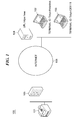
- FIG. 1 is a schematic diagram of a remote maintenance system 100 including an image forming apparatus 101 according to an embodiment of the present invention.
- the remote maintenance system 100 is comprised of the image forming apparatus 101, a firewall 105, the Internet 106, a session management server 104, and call center terminals 102 and 103.
- the image forming apparatus 101, and the call center terminals 102 and 103 are each equipped with a communication function as an HTTP client. Further, the image forming apparatus 101, and the call center terminals 102 and 103 each have a remote maintenance function using e.g. voice and moving image communication, and remote control, and operate as communication partners in the remote maintenance.
- a remote maintenance function using e.g. voice and moving image communication, and remote control, and operate as communication partners in the remote maintenance.
- the image forming apparatus 101 accesses the session management server 104 connected to the Internet 106 via the firewall 105, by using HTTP.
- the image forming apparatus 101 designates a terminal ID of a call center terminal for the session management server 104, to thereby call the designated call center terminal and establish a session therewith. Then, the image forming apparatus 101 transmits and receives data to and from the called call center terminal via the session management server 104.
- the session management server 104 is equipped with a communication function as an HTTP server.
- the session management server 104 manages sessions between the image forming apparatus 101 and the call center terminals 102 and 103.
- the call center terminals 102 and 103 connect to the session management server 104 by using HTTP.
- the call center terminal 102 is a terminal which is operated by a receiving operator of the call center, as a reception terminal for receiving access from the image forming apparatus 101. Further, the call center terminal 102 dispatches a session established first with the image forming apparatus 101 to the call center terminal 103 as a maintenance terminal for performing maintenance work.
- the call center terminal 103 is a terminal operated by a maintenance operator at the call center as the maintenance terminal for performing maintenance work on the image forming apparatus 101.
- the call center terminal 103 performs remote maintenance of the image forming apparatus 101, by voice and moving image communication and remote control, in the session with the image forming apparatus 101 dispatched from the call center terminal 102.
- the HTTP protocol is used for connection between the image forming apparatus 101 and the session management server 104, any other communication protocol having high compatibility with a firewall may be used.
- HTTP protocol is used for connection between the call center terminals 102 and 103 and the session management server 104, any other communication protocol may be used.
- the image forming apparatus 101 accesses the information processing apparatuses (call center terminals 102 and 103) to transmit and receive maintenance work data including voice data and moving image data for performing the maintenance work on the image forming apparatus 101 to and from the information processing apparatuses.
- the above-mentioned voice data and moving image data, and data for remote control are used as the maintenance work data.
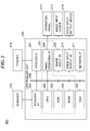
- FIG. 2 is a block diagram of the hardware configuration of the image forming apparatus 101 appearing in FIG. 1 .
- the image forming apparatus 101 is comprised of a controller unit 220, a scanner 215, a printer 216, an operation panel 212, an image input device 213, and a voice input/output device 214.
- controller unit 220 is comprised of a scanner interface 201, a CPU 202, a ROM 203, a RAM 204, an HDD 205, a printer interface 207, a panel operation interface 208, an image input interface 209, a voice input/output interface 210, and a network interface 211, which are connected to each other via a system bus 206.
- the CPU 202 performs centralized control of access to various devices connected to the system bus 206 based on a control program stored in the ROM 203 or the HDD 205 to thereby control the overall operation of the image forming apparatus 101.
- a communication process is a process executed by loading a program stored in the HDD 205 into the RAM 204 by the CPU 202.
- the RAM 204 mainly functions as a main memory and a work area for the CPU 202, and can expand its memory capacity by connecting an optional RAM to an expansion port, not shown.
- the HDD 205 stores a boot program, various application programs, font data, user files, editing files, and so forth. Note that not only the HDD 205, but also an SD card, a flash memory, or the like may be used as an external storage device.
- the scanner interface 201 controls input of an image from the scanner 215.
- the printer interface 207 controls output of an image to the printer 216.
- the panel operation interface 208 receives an operation from a user, and controls display on the operation panel 212 as a display section configured to display a maintenance work screen for displaying a moving image from the call center terminal 102 or 103, and input of various setting information set on the operation panel 212 as an operating section.
- the image input interface 209 controls input of an image from the image input device 213, such as a camera.
- the voice input/output interface 210 controls input and output of a voice from and to the voice input/output device 214, such as a head set.
- the network interface 211 performs data communication with an external network via a network cable.
- the image forming apparatus 101 described above is capable of operating in two operating modes: a normal mode in which electric power is supplied to all of units of the image forming apparatus 101, shown in FIG. 2 , and a power-saving mode in which electric power is supplied only to a block 217 of several units.
- FIG. 3A is a diagram showing call center connection information
- FIG. 3B is a diagram showing redial setting information. These are stored in the HDD 205.
- the call center connection information is formed by a session management server URL and a first-time connection destination terminal ID.
- the session management server URL indicates a URL of the session management server 104.
- the first-time connection destination terminal ID indicates a terminal ID of one of call center terminals which is to be accessed first, and in the present embodiment, it indicates the terminal ID of the call center terminal 102.
- the redial setting information is formed by a redial button ID, a redial destination terminal ID, the name of a person in charge at a redial destination, an image of the person in charge at the redial destination, a connected user name, a discontinued time, a redial button display period expiration time, and a discontinued screen.
- the redial button ID displays identification information for indentifying this redial setting information.
- the redial destination terminal ID indicates a terminal ID of a call center terminal the telephone number of which is to be redialed when the redial button is pressed.
- the name of a person in charge at a redial destination indicates the name of the operator as a person in charge at the call center terminal to which the image forming apparatus has been connected, and the image of the person in charge at the redial destination indicates face photograph data of the operator.
- the connected user name indicates an account name of the user having been receiving the remote maintenance service.
- the discontinued time indicates a time at which the connection was discontinued.
- the redial button display period expiration time indicates a time limit up to which the redial button is displayed on the image forming apparatus 101, for resuming the interrupted remote maintenance work.
- the discontinued screen indicates a final screen displayed before the user discontinued receiving the remote maintenance service. In the case of the illustrated example, the discontinued screen is indicated by a screen ID of a copy staple setting screen.
- FIG. 4 is a block diagram of the software configuration of the image forming apparatus 101 appearing in FIG. 1 .
- the image forming apparatus 101 is comprised of a user interface (UI) section 301, a session controller 302, a data transmission/reception section 303, and a power supply controller 304. These sections are realized by loading programs stored in the HDD 205 into the RAM 204 and executing the loaded programs by the CPU 202.
- UI user interface
- the user interface section 301 controls display on the operation panel 212 and input of various setting information set on the operation panel 212, via the panel operation interface 208.
- the session controller 302 accesses the session management server 104 via the network interface 211 according to the settings of the call center connection information shown in FIG. 3A , which is stored in the HDD 205.
- the data transmission/reception section 303 transmits and receives data, such as voice data, moving image data, remote control data, and information included in the redial setting information, in a session established by the session controller 302 via the network interface 211.
- the data transmission/ reception section 303 controls the voice input/output interface 210, the image input interface 209, the panel operation interface 208, and so forth, as required.
- the power supply controller 304 performs control concerning the power supply, such as control performed when shutdown is instructed e.g. by a user through switching-off of the power switch, and control of where to supply power.
- FIG. 5 is a flowchart of a communication process for communicating with the call center terminals 102 and 103, which is executed by the CPU 202 appearing in FIG. 2
- FIG. 6 is a continuation of FIG. 5 .
- the user interface section 301 displays a call center calling button, not shown (step S501).
- the user interface section 301 determines whether or not the redial setting information is stored in the HDD 205 (step S502).
- step S502 If it is determined in the step S502 that the redial setting information is not stored (NO to the step S502), the user interface section 301 determines whether the call center calling button has been pressed (step S503).
- step S503 If it is determined in the step S503 that the call center calling button has not been pressed (NO to the step S503), the CPU 202 returns to the step S501.
- step S503 If it is determined in the step S503 that the call center calling button has been pressed (YES to the step S503), the CPU 202 proceeds to a step S504 in FIG. 6 , wherein the session controller 302 reads the session management server URL of the call center connection information shown in FIG. 3A from the HDD 205, and accesses the session management server 104 by using HTTP (step S504).
- the session controller 302 reads the first-time connection destination terminal ID of the call center connection information from the HDD 205, and sends the read ID to the session management server 104 to thereby establish a session with the call center terminal 102 (step S505), and further establish a session with the call center terminal 103 (step S506).
- the destination to and from which data is transmitted and received by the data transmission/reception section 303 is changed to the call center terminal 103, whereby the user of the image forming apparatus 101 performs transmission and reception of voice data, moving image data, and remote control data, and so forth for the maintenance work to and from the call center terminal 103 (step S507).
- remote control of the image forming apparatus 101 is performed by the maintenance operator from the call center terminal 103.
- the session controller 302 determines whether or not to discontinue the remote maintenance service (step S508).
- the discontinuation at this time includes discontinuation caused by receiving a discontinuation instruction from the user via the user interface section 301, and discontinuation caused by receiving a discontinuation instruction from the call center terminal 103 via the data transmission/reception section 303.
- the CPU 202 determines whether or not the remote maintenance work has been finished by eliminating the trouble through the remote maintenance work (step S509).
- the CPU 202 If it is determined in the step S509 that the remote maintenance work has not been finished (NO to the step S509), the CPU 202 returns to the step S507, whereas if the remote maintenance work has been finished (YES to the step S509), the CPU 202 terminates the present process.
- the data transmission/reception section 303 receives part of the redial setting information shown in FIG. 3B (step S510).
- the part of the redial setting information is formed by the redial destination terminal ID, the name of the person in charge at the redial destination, the image of the person in charge at the redial destination, the discontinued time, and the redial button display period expiration time.
- the data transmission/reception section 303 stores the above-mentioned items of information, in the HDD 205, and further, the user interface section 301 stores the remainder of the redial setting information, i.e. the redial button ID, the connected user name, and the discontinued screen, in the HDD 205 (S511). That is, in this step S511, the redial setting information is stored in the HDD 205.
- the step S511 corresponds to the operation of a storage unit configured to store, in a case where during connection with the information processing apparatus, the image forming apparatus is required to be disconnected and then reconnected, identification information (redial destination terminal ID) for identifying an information processing apparatus to be reconnected, in a storage section (HDD 205).
- the session controller 302 disconnects the session with the call center terminal 103 (step S513), and the CPU 202 returns to the step S501 in FIG. 5 .
- the user interface section 301 reads out the redial information stored in the HDD 205 (step S514).
- the user interface section 301 acquires the user information of the logged-in user of the image forming apparatus 101, and determines whether or not the logged-in user has the administrator authority (step S515).
- the user interface section 301 determines whether or not the name of the logged-in user matches the connected user name of the redial setting information (step S516).
- the CPU 202 proceeds to the step S503.
- the processing in this step is for excluding users other than a user having the administrator authority and the user having the connected user name of the redial setting information.
- the present embodiment is configured to store the reconnection information (redial setting information) in the storage section, and display an icon only when the user having logged in the image forming apparatus 101 is one of predetermined users.
- the predetermined users are users having the administrator authority and the user having the connected user name of the redial setting information, by way of example, but they may be other users.
- the user interface section 301 determines whether or not the current date and time has passed the redial button display period expiration time of the redial setting information (step S517).
- step S517 If it is determined in the step S517 that the current date and time has passed the redial button display period expiration time (YES to the step S517), the CPU 202 proceeds to the step S503.
- the user interface section 301 determines whether or not the current date and time is included in a display time period which starts from the discontinued time of the redial setting information, and is separately and independently set in the image forming apparatus 101 (step S518).
- step S518 If it is determined in the step S518 that the current date and time is not included in the display time period (NO to the step S518), the CPU 202 proceeds to the step S503.
- the user interface section 301 displays the redial button (step S519).
- the user interface section 301 reads out the name of the person in charge at the redial destination and image of the person in charge at the redial destination of the redial setting information, and displays them together with the redial button.
- the step S519 corresponds to the operation of an icon display unit configured to display an icon for enabling a user to give an instruction for reconnection to the information processing apparatus identified by the identification information (redial destination terminal ID) on the display section, in a case where the reconnection information (redial setting information) is stored in the storage section.
- a button is displayed as an example of the icon, but any other suitable icon other than the button may be displayed.
- information on the information processing apparatus to which the image forming apparatus was connected before disconnection is displayed on the display section.
- the information on the information processing apparatus there are displayed the name of the person in charge at the redial destination and image of the person in charge at the redial destination of the redial setting information, by way of example, but this is not limitative.
- the user interface section 301 determines whether or not the call center calling button has been pressed (step S520).
- step S520 If it is determined in the step S520 that the call center calling button has not been pressed (NO to the step S520), the CPU 202 proceeds to a step S523, referred to hereinafter, in FIG. 6 .
- the user interface section 301 displays a screen showing a message "Although the redial button is displayed, it is not pressed but the call center calling button is pressed instead.” (step S521), to prompt the user to confirm that this operation is intended by the user.
- an icon is displayed on the display section, and further another icon (call center calling button) is displayed for enabling the user to give an instruction for performing maintenance work on the image forming apparatus 101 by connecting to the information processing apparatus.
- a screen indicating that the call center calling button has been operated for giving the instruction is displayed on the display section.
- the user interface section 301 determines whether or not an instruction has been given for continuing processing to be executed in accordance with pressing of the call center calling button so as to receive the remote maintenance service anew (step S522).
- step S522 If it is determined in the step S522 that the instruction for continuing the processing has been given (YES to the step S522), the CPU 202 proceeds to the step S504 in FIG. 6 .
- the CPU 202 proceeds to the step S523 in FIG. 6 , wherein the user interface section 301 determines whether or not the redial button has been pressed by the user.
- step S523 If it is determined in the step S523 that the redial button has not been pressed by the user (NO to the step S523), the CPU 202 returns to the step 501 in FIG. 5 .
- the user interface section 301 reads out the discontinued screen of the redial setting information, and displays the discontinued screen (step S524). This makes it possible to smoothly resume the remote maintenance work from the discontinued point after the redial.
- the step S524 corresponds to the operation of a screen display unit configured to display the maintenance work screen indicated by the screen information (discontinued screen) on the display section.
- the session controller 302 reads out the session management server URL of the call center connection information shown in FIG. 3A from the HDD 205, and accesses the session management server 104 by using HTTP (step S525).
- the session controller 302 reads out the redial destination terminal ID of the call center connection information, and sends the same to the session management server 104, to thereby establish a session with the call center terminal 103 (step S526).
- This makes it possible to directly connect to the call center terminal 103 which actually provides the remote maintenance service, by skipping the session establishment with the call center terminal 102 which is to be executed in the step S505 when connecting the call center anew.
- the step S526 corresponds to the operation of a reconnection unit configured to reconnect to the information processing apparatus identified by the identification information (redial destination terminal ID), in a case where the user has instructed the reconnection by using the displayed icon.
- the data transmission/reception section 303 determines whether or not an instruction for deleting the redial button has been received from the call center terminal 103 (step S527).
- the icon is inhibited from being displayed.
- step S527 If it is determined in the step S527 that the an instruction for deleting the redial button has not been received from the call center terminal 103 (NO to the step S527), the CPU 202 proceeds to the step S507.
- step S527 if it is determined in the step S527 that the an instruction for deleting the redial button has been received from the call center terminal 103 (YES to the step S527), the user interface section 301 inhibits the redial button from being displayed, and deletes the redial setting information stored in the HDD 205 (step S528), followed by the CPU 202 proceeding to the step S507.
- the image forming apparatus in a case where the image forming apparatus is once disconnected from the information processing apparatus and is then connected thereto again, it stores reconnection information including screen information indicating a maintenance work screen being displayed on the display section before discontinuing the display on the display section due to the disconnection, in a storage section (step S511), and when the reconnection is instructed by the user, the maintenance work screen indicated by the stored screen information is displayed on the display section (step S524). Therefore, the user is capable of easily understanding the details of the maintenance work when the image forming apparatus is reconnected to the information processing apparatus.
- Embodiments of the present invention can also be realized by a computer of a system or apparatus that reads out and executes computer executable instructions recorded on a storage medium (e.g., non-transitory computer-readable storage medium) to perform the functions of one or more of the above-described embodiment(s) of the present invention, and by a method performed by the computer of the system or apparatus by, for example, reading out and executing the computer executable instructions from the storage medium to perform the functions of one or more of the above-described embodiment(s).
- the computer may comprise one or more of a central processing unit (CPU), micro processing unit (MPU), or other circuitry, and may include a network of separate computers or separate computer processors.
- the computer executable instructions may be provided to the computer, for example, from a network or the storage medium.
- the storage medium may include, for example, one or more of a hard disk, a random-access memory (RAM), a read only memory (ROM), a storage of distributed computing systems, an optical disk (such as a compact disc (CD), digital versatile disc (DVD), or Blu-ray Disc (BD)TM), a flash memory device, a memory card, and the like.
- An image forming apparatus capable of reducing the trouble of operation of the user, when being disconnected from and reconnected to an information processing apparatus for transmission and reception of maintenance work data for maintenance work.
- identification information for identifying the information processing apparatus to be reconnected is stored in a storage section.
- An icon for enabling user to reconnect to the information processing apparatus identified by the identification information is displayed on a display section when the identification information is stored. The image forming apparatus reconnects to the information processing apparatus when the reconnection is instructed by the user using the icon.
Landscapes
- Engineering & Computer Science (AREA)
- Signal Processing (AREA)
- Multimedia (AREA)
- Theoretical Computer Science (AREA)
- Computer Networks & Wireless Communication (AREA)
- Physics & Mathematics (AREA)
- General Physics & Mathematics (AREA)
- General Engineering & Computer Science (AREA)
- Business, Economics & Management (AREA)
- Human Computer Interaction (AREA)
- Human Resources & Organizations (AREA)
- Economics (AREA)
- Entrepreneurship & Innovation (AREA)
- Strategic Management (AREA)
- General Business, Economics & Management (AREA)
- Quality & Reliability (AREA)
- Operations Research (AREA)
- Marketing (AREA)
- Tourism & Hospitality (AREA)
- Computer Security & Cryptography (AREA)
- Facsimiles In General (AREA)
- Telephonic Communication Services (AREA)
- Accessory Devices And Overall Control Thereof (AREA)
- Control Or Security For Electrophotography (AREA)
- User Interface Of Digital Computer (AREA)
Applications Claiming Priority (1)
| Application Number | Priority Date | Filing Date | Title |
|---|---|---|---|
| JP2013168570A JP6366239B2 (ja) | 2013-08-14 | 2013-08-14 | 画像形成装置及びその制御方法、並びにプログラム |
Publications (2)
| Publication Number | Publication Date |
|---|---|
| EP2840534A2 true EP2840534A2 (de) | 2015-02-25 |
| EP2840534A3 EP2840534A3 (de) | 2015-04-01 |
Family
ID=51357745
Family Applications (1)
| Application Number | Title | Priority Date | Filing Date |
|---|---|---|---|
| EP20140180773 Withdrawn EP2840534A3 (de) | 2013-08-14 | 2014-08-13 | Bilderzeugungsvorrichtung, die Daten zu Wartungsarbeiten von Servicecenter sendet und empfängt, mit Wiederverbindungmechanismus, der vom Benutzer über ein Ikone auf einer Anzeige gestartet wird |
Country Status (5)
| Country | Link |
|---|---|
| US (1) | US9979842B2 (de) |
| EP (1) | EP2840534A3 (de) |
| JP (1) | JP6366239B2 (de) |
| KR (2) | KR101731381B1 (de) |
| CN (1) | CN104375948B (de) |
Families Citing this family (9)
| Publication number | Priority date | Publication date | Assignee | Title |
|---|---|---|---|---|
| JP6366239B2 (ja) * | 2013-08-14 | 2018-08-01 | キヤノン株式会社 | 画像形成装置及びその制御方法、並びにプログラム |
| JP6459180B2 (ja) * | 2014-02-10 | 2019-01-30 | 富士ゼロックス株式会社 | 障害予測システム、障害予測装置、ジョブ実行装置およびプログラム |
| CN107770352B (zh) * | 2016-08-15 | 2020-10-30 | 中国移动通信有限公司研究院 | 一种拨号处理方法及装置 |
| JP6555218B2 (ja) * | 2016-09-21 | 2019-08-07 | 京セラドキュメントソリューションズ株式会社 | 情報処理システムおよび情報処理方法 |
| JP2018112860A (ja) * | 2017-01-11 | 2018-07-19 | 富士ゼロックス株式会社 | 情報処理装置及びプログラム |
| JP6703310B2 (ja) * | 2017-06-30 | 2020-06-03 | 京セラドキュメントソリューションズ株式会社 | リモート通信制御システム、リモートメンテナンスシステムおよびリモートメンテナンスプログラム |
| CN110557510A (zh) * | 2018-05-31 | 2019-12-10 | 京瓷办公信息系统株式会社 | 图像形成装置、图像形成系统及通信处理方法 |
| US10999469B2 (en) * | 2018-11-20 | 2021-05-04 | Canon Kabushiki Kaisha | Transmission apparatus and control method |
| JP7503247B2 (ja) * | 2020-09-30 | 2024-06-20 | ブラザー工業株式会社 | 画像処理装置及び画像処理プログラム |
Citations (3)
| Publication number | Priority date | Publication date | Assignee | Title |
|---|---|---|---|---|
| JP2005208974A (ja) | 2004-01-23 | 2005-08-04 | Canon Inc | 画像処理装置のヘルプシステム |
| JP2007221709A (ja) | 2006-02-20 | 2007-08-30 | Ricoh Co Ltd | ネットワーク画像入出力システムおよび画像形成装置 |
| US20090089457A1 (en) * | 2007-09-28 | 2009-04-02 | Konica Minolta Systems Laboratory, Inc. | Reconnecting a host computer with a networked printer having a dynamic network address |
Family Cites Families (48)
| Publication number | Priority date | Publication date | Assignee | Title |
|---|---|---|---|---|
| US5303005A (en) | 1990-01-31 | 1994-04-12 | Minolta Camera Kabushiki Kaisha | Image forming apparatus with improved maintenance control |
| JP3791089B2 (ja) | 1997-01-27 | 2006-06-28 | セイコーエプソン株式会社 | ネットワーク対応型印刷装置及び印刷方法及びネットワーク印刷システム |
| US6353445B1 (en) * | 1998-11-25 | 2002-03-05 | Ge Medical Systems Global Technology Company, Llc | Medical imaging system with integrated service interface |
| US6330499B1 (en) * | 1999-07-21 | 2001-12-11 | International Business Machines Corporation | System and method for vehicle diagnostics and health monitoring |
| US7707149B2 (en) * | 2001-04-04 | 2010-04-27 | Alorica, Inc | Method, system, and program for customer service and support management |
| US7792889B1 (en) * | 2001-04-04 | 2010-09-07 | Alorica Inc | Method, system, and program for customer service and support management |
| JP2003076533A (ja) | 2001-06-19 | 2003-03-14 | Fuji Photo Film Co Ltd | 画像形成装置の管理方法および管理システム |
| US20030025732A1 (en) * | 2001-07-31 | 2003-02-06 | Prichard Scot D. | Method and apparatus for providing customizable graphical user interface and screen layout |
| US7023979B1 (en) * | 2002-03-07 | 2006-04-04 | Wai Wu | Telephony control system with intelligent call routing |
| US20040181443A1 (en) * | 2003-03-10 | 2004-09-16 | Horton Carl A. | Method and apparatus for the management of infrastructure assets, work orders,service requests, and work flows, utilizing an integrated call center, database, GIS system, and wireless handheld device |
| US20040260704A1 (en) | 2003-06-23 | 2004-12-23 | Moore Keith E. | User-requested remote assistance for printing devices |
| JP4698169B2 (ja) | 2003-07-24 | 2011-06-08 | 株式会社リコー | ユーザ認証方法、画像形成装置 |
| JP4371790B2 (ja) * | 2003-12-03 | 2009-11-25 | キヤノン株式会社 | 画像形成システムおよび表示制御方法およびコンピュータが読み取り可能なプログラムを格納した記憶媒体およびプログラム |
| US7236835B2 (en) | 2005-05-24 | 2007-06-26 | Murata Kikai Kabushiki Kaisha | Remote maintenance system, communication terminal device and center device |
| JP4712639B2 (ja) | 2005-09-13 | 2011-06-29 | 株式会社リコー | ネットワーク印刷システム、印刷装置、印刷データ生成装置、ネットワーク印刷方法、印刷方法、印刷データ生成方法およびプログラム |
| US20070116185A1 (en) * | 2005-10-21 | 2007-05-24 | Sbc Knowledge Ventures L.P. | Real time web-based system to manage trouble tickets for efficient handling |
| JP4348330B2 (ja) * | 2005-11-11 | 2009-10-21 | 本田技研工業株式会社 | 情報配信システム、このシステムを構成する車両及びメッセージ出力方法 |
| US9621559B2 (en) | 2006-06-19 | 2017-04-11 | Bomgar Corporation | Network apparatus for secure remote access and control |
| US8582750B2 (en) * | 2006-07-31 | 2013-11-12 | Cisco Technology, Inc. | Connection recovery in a call center |
| US7533178B2 (en) | 2006-10-31 | 2009-05-12 | Cisco Technology, Inc. | Resuming a computing session when rebooting a computing device |
| US20100055656A1 (en) * | 2007-03-08 | 2010-03-04 | Koninklijke Philips Electronics N. V. | System and method for providing verbal and graphical instruction from a remote healthcare monitoring service helpdesk |
| KR100912172B1 (ko) * | 2007-06-28 | 2009-08-14 | 이종원 | 경력인증시스템 및 방법, 기록매체 |
| US20090063275A1 (en) * | 2007-08-07 | 2009-03-05 | Asi Barak | Method and system to facilitate setup of a proxy web store by an itemized selection approach |
| JP5003556B2 (ja) * | 2008-03-28 | 2012-08-15 | 富士通株式会社 | 通信検知装置、通信検知方法、及び通信検知プログラム |
| US20090307027A1 (en) * | 2008-06-09 | 2009-12-10 | Car Research, Inc. | Repair order management |
| JP4770898B2 (ja) * | 2008-09-18 | 2011-09-14 | コニカミノルタビジネステクノロジーズ株式会社 | 画像処理装置 |
| JP2010093585A (ja) * | 2008-10-08 | 2010-04-22 | Fujitsu Ltd | ネットワーク接続制御プログラム及び方法、ネットワーク接続プログラム及び方法、認証装置 |
| CA2897462A1 (en) * | 2009-02-11 | 2010-05-04 | Certusview Technologies, Llc | Management system, and associated methods and apparatus, for providing automatic assessment of a locate operation |
| JP5489643B2 (ja) | 2009-10-26 | 2014-05-14 | キヤノン株式会社 | 管理システム、画像形成装置、及びその方法 |
| JP5381765B2 (ja) * | 2010-02-08 | 2014-01-08 | ブラザー工業株式会社 | プリンタ |
| KR20110107579A (ko) * | 2010-03-25 | 2011-10-04 | 삼성전자주식회사 | 인쇄 제어 단말장치 및 펌웨어 업그레이드 방법 |
| US8789205B2 (en) * | 2010-04-21 | 2014-07-22 | Microsoft Corporation | Role-based graphical user interfaces |
| US20110320277A1 (en) * | 2010-06-24 | 2011-12-29 | Isaacs Charles H | Network-Based Information and Advertising System |
| JP5482530B2 (ja) * | 2010-07-16 | 2014-05-07 | 株式会社リコー | 機器管理システム、機器管理装置、及び機器管理方法 |
| US20120084369A1 (en) * | 2010-09-30 | 2012-04-05 | Microsoft Corporation | Unified Reconnection To Multiple Remote Servers |
| US9069047B2 (en) * | 2011-04-08 | 2015-06-30 | Madhu Nallabelli | Talking power management utility |
| JP5786535B2 (ja) | 2011-08-08 | 2015-09-30 | 株式会社リコー | 機器、情報処理方法、情報処理プログラム、及び記録媒体 |
| JP5810727B2 (ja) * | 2011-08-09 | 2015-11-11 | オムロン株式会社 | データ管理装置、非接触記憶媒体、これらを搭載する電子機器、機器使用支援システム、データ管理方法、制御プログラム、および、記録媒体 |
| US9148447B2 (en) * | 2011-08-31 | 2015-09-29 | Bank Of America Corporation | Safe services framework |
| US9195779B2 (en) * | 2011-10-18 | 2015-11-24 | Verizon Patent And Licensing Inc. | Crowd-sourced problem solving |
| JP5810826B2 (ja) * | 2011-10-24 | 2015-11-11 | コニカミノルタ株式会社 | 画像処理システム、画像形成装置、制御方法、および制御プログラム |
| US8964196B2 (en) * | 2012-02-02 | 2015-02-24 | Kabushiki Kaisha Toshiba | System for connecting to next generation networks |
| JP6019755B2 (ja) | 2012-05-29 | 2016-11-02 | 株式会社リコー | 画像形成装置、印刷システム |
| US20140222462A1 (en) * | 2013-02-07 | 2014-08-07 | Ian Shakil | System and Method for Augmenting Healthcare Provider Performance |
| US9912817B2 (en) * | 2013-05-23 | 2018-03-06 | Verizon Patent And Licensing Inc. | Presence enabled call center |
| JP6366239B2 (ja) * | 2013-08-14 | 2018-08-01 | キヤノン株式会社 | 画像形成装置及びその制御方法、並びにプログラム |
| JP6378584B2 (ja) * | 2014-08-29 | 2018-08-22 | キヤノン株式会社 | 通信システム、画像処理装置、画像処理装置の制御方法、及びプログラム |
| US9805526B2 (en) * | 2015-12-11 | 2017-10-31 | The Boeing Company | Fault monitoring for vehicles |
-
2013
- 2013-08-14 JP JP2013168570A patent/JP6366239B2/ja active Active
-
2014
- 2014-08-07 KR KR1020140101609A patent/KR101731381B1/ko not_active Expired - Fee Related
- 2014-08-11 CN CN201410392486.8A patent/CN104375948B/zh active Active
- 2014-08-12 US US14/457,305 patent/US9979842B2/en active Active
- 2014-08-13 EP EP20140180773 patent/EP2840534A3/de not_active Withdrawn
-
2017
- 2017-04-24 KR KR1020170052154A patent/KR101861079B1/ko active Active
Patent Citations (3)
| Publication number | Priority date | Publication date | Assignee | Title |
|---|---|---|---|---|
| JP2005208974A (ja) | 2004-01-23 | 2005-08-04 | Canon Inc | 画像処理装置のヘルプシステム |
| JP2007221709A (ja) | 2006-02-20 | 2007-08-30 | Ricoh Co Ltd | ネットワーク画像入出力システムおよび画像形成装置 |
| US20090089457A1 (en) * | 2007-09-28 | 2009-04-02 | Konica Minolta Systems Laboratory, Inc. | Reconnecting a host computer with a networked printer having a dynamic network address |
Non-Patent Citations (2)
| Title |
|---|
| IPSJ (INFORMATION PROCESSING SOCIETY OF JAPAN) JOURNAL, vol. 44, no. 3, 15 March 2003 (2003-03-15), pages 553 - 560 |
| IPSJ JOURNAL, vol. 44, no. 3, pages 553 - 560 |
Also Published As
| Publication number | Publication date |
|---|---|
| EP2840534A3 (de) | 2015-04-01 |
| KR20170052540A (ko) | 2017-05-12 |
| KR20150020071A (ko) | 2015-02-25 |
| JP6366239B2 (ja) | 2018-08-01 |
| US20150049161A1 (en) | 2015-02-19 |
| CN104375948A (zh) | 2015-02-25 |
| KR101861079B1 (ko) | 2018-05-28 |
| US9979842B2 (en) | 2018-05-22 |
| KR101731381B1 (ko) | 2017-05-11 |
| CN104375948B (zh) | 2018-05-04 |
| JP2015037258A (ja) | 2015-02-23 |
Similar Documents
| Publication | Publication Date | Title |
|---|---|---|
| EP2840534A2 (de) | Bilderzeugungsvorrichtung die Daten zu Wartungsarbeiten von Servicecenter sendet und empfängt, enthält Wiederverbingundmechanismus der vom Benutzer über ein Ikone auf einer Anzeige gestartet wird | |
| EP2854079A1 (de) | Bilderverarbeitungsvorrichtung, Empfangen und Senden von Daten für Wartungsarbeiten zum und vom Remote-Service-Center, einschließlich der Wiederverbindung zum Remote-Service-Center nach Neustart | |
| US10148852B2 (en) | Image processing system, control apparatus, image processing apparatus, and methods of controlling these | |
| CN104735279B (zh) | 图像形成装置、系统及图像形成装置和系统的控制方法 | |
| US10341519B2 (en) | Communication system, image forming apparatus, method of controlling the same, and storage medium | |
| JP6204821B2 (ja) | 画像形成装置、その制御方法、及びプログラム | |
| US10164784B2 (en) | Communication terminal, communication system, and data transmission method | |
| CN113079588A (zh) | 控制方法、装置及设备和存储介质 | |
| JP6724423B2 (ja) | 通信端末、通信システム、出力方法、及びプログラム | |
| JP2015191320A (ja) | 情報処理装置、デバイス共有システムおよびデバイス接続方法 | |
| JP6184246B2 (ja) | 画像形成装置及びその制御方法、並びにプログラム | |
| JP2014116829A (ja) | 画像形成装置及びその制御方法、並びにプログラム | |
| JP2019201322A (ja) | 遠隔メンテナンスシステム及び情報処理方法 | |
| JP2014059720A (ja) | リモート支援システム、画像形成装置、及び情報処理装置 |
Legal Events
| Date | Code | Title | Description |
|---|---|---|---|
| PUAI | Public reference made under article 153(3) epc to a published international application that has entered the european phase |
Free format text: ORIGINAL CODE: 0009012 |
|
| 17P | Request for examination filed |
Effective date: 20140813 |
|
| AK | Designated contracting states |
Kind code of ref document: A2 Designated state(s): AL AT BE BG CH CY CZ DE DK EE ES FI FR GB GR HR HU IE IS IT LI LT LU LV MC MK MT NL NO PL PT RO RS SE SI SK SM TR |
|
| AX | Request for extension of the european patent |
Extension state: BA ME |
|
| PUAL | Search report despatched |
Free format text: ORIGINAL CODE: 0009013 |
|
| AK | Designated contracting states |
Kind code of ref document: A3 Designated state(s): AL AT BE BG CH CY CZ DE DK EE ES FI FR GB GR HR HU IE IS IT LI LT LU LV MC MK MT NL NO PL PT RO RS SE SI SK SM TR |
|
| AX | Request for extension of the european patent |
Extension state: BA ME |
|
| RIC1 | Information provided on ipc code assigned before grant |
Ipc: G06Q 10/00 20120101AFI20150220BHEP Ipc: H04N 1/00 20060101ALN20150220BHEP Ipc: H04N 1/32 20060101ALN20150220BHEP |
|
| R17P | Request for examination filed (corrected) |
Effective date: 20151001 |
|
| RBV | Designated contracting states (corrected) |
Designated state(s): AL AT BE BG CH CY CZ DE DK EE ES FI FR GB GR HR HU IE IS IT LI LT LU LV MC MK MT NL NO PL PT RO RS SE SI SK SM TR |
|
| 17Q | First examination report despatched |
Effective date: 20160108 |
|
| APBK | Appeal reference recorded |
Free format text: ORIGINAL CODE: EPIDOSNREFNE |
|
| APBN | Date of receipt of notice of appeal recorded |
Free format text: ORIGINAL CODE: EPIDOSNNOA2E |
|
| APBR | Date of receipt of statement of grounds of appeal recorded |
Free format text: ORIGINAL CODE: EPIDOSNNOA3E |
|
| APAF | Appeal reference modified |
Free format text: ORIGINAL CODE: EPIDOSCREFNE |
|
| APBX | Invitation to file observations in appeal sent |
Free format text: ORIGINAL CODE: EPIDOSNOBA2E |
|
| APBT | Appeal procedure closed |
Free format text: ORIGINAL CODE: EPIDOSNNOA9E |
|
| STAA | Information on the status of an ep patent application or granted ep patent |
Free format text: STATUS: THE APPLICATION HAS BEEN WITHDRAWN |
|
| 18W | Application withdrawn |
Effective date: 20220531 |