EP2840176A1 - Nähmaschinenzuführmechanismus - Google Patents
Nähmaschinenzuführmechanismus Download PDFInfo
- Publication number
- EP2840176A1 EP2840176A1 EP14172009.4A EP14172009A EP2840176A1 EP 2840176 A1 EP2840176 A1 EP 2840176A1 EP 14172009 A EP14172009 A EP 14172009A EP 2840176 A1 EP2840176 A1 EP 2840176A1
- Authority
- EP
- European Patent Office
- Prior art keywords
- sewing machine
- feed mechanism
- belt
- side frames
- airbag
- Prior art date
- Legal status (The legal status is an assumption and is not a legal conclusion. Google has not performed a legal analysis and makes no representation as to the accuracy of the status listed.)
- Granted
Links
- 238000009958 sewing Methods 0.000 title claims abstract description 47
- 238000003825 pressing Methods 0.000 claims abstract description 27
- 239000004744 fabric Substances 0.000 claims abstract description 20
- 230000001105 regulatory effect Effects 0.000 claims description 4
- 238000004519 manufacturing process Methods 0.000 abstract description 5
- 239000012530 fluid Substances 0.000 description 3
- 230000000712 assembly Effects 0.000 description 1
- 238000000429 assembly Methods 0.000 description 1
- 238000000034 method Methods 0.000 description 1
- 238000012986 modification Methods 0.000 description 1
- 230000004048 modification Effects 0.000 description 1
Images
Classifications
-
- D—TEXTILES; PAPER
- D05—SEWING; EMBROIDERING; TUFTING
- D05B—SEWING
- D05B27/00—Work-feeding means
- D05B27/10—Work-feeding means with rotary circular feed members
- D05B27/14—Work-feeding means with rotary circular feed members rotating discontinuously
-
- D—TEXTILES; PAPER
- D05—SEWING; EMBROIDERING; TUFTING
- D05B—SEWING
- D05B27/00—Work-feeding means
-
- D—TEXTILES; PAPER
- D05—SEWING; EMBROIDERING; TUFTING
- D05B—SEWING
- D05B27/00—Work-feeding means
- D05B27/10—Work-feeding means with rotary circular feed members
-
- D—TEXTILES; PAPER
- D05—SEWING; EMBROIDERING; TUFTING
- D05B—SEWING
- D05B27/00—Work-feeding means
- D05B27/10—Work-feeding means with rotary circular feed members
- D05B27/12—Work-feeding means with rotary circular feed members rotating continuously
-
- D—TEXTILES; PAPER
- D05—SEWING; EMBROIDERING; TUFTING
- D05B—SEWING
- D05B35/00—Work-feeding or -handling elements not otherwise provided for
Definitions
- the present invention relates to a feed mechanism used to transport fabrics from a loading end to an unloading end of a sewing machine for sewing, and more particularly, to a sewing machine feed mechanism that internally includes a pressing mechanism configured as an airbag.
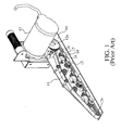
- a conventional sewing machine feed mechanism as shown in Fig. 1 , includes a feed belt 11 rotatably fitted on two spaced wheels 12a, 12b, a motor 13 connected to the feed belt 11 and driving the same to rotate, and a plurality of cylinders 14 connected to a pressure control system.
- the feed belt 11 brings fabrics placed between the feed belt 11 and a work table 10 to move horizontally into a stitch forming area of the sewing machine.
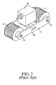
- the cylinders 14 respectively internally include a movable piston for actuating at least one pressing unit, and has a compressible fluid filled therein.
- the pressing unit includes rollers 15, pins 16, side brackets 17 and a pressing plate 18, and is in contact with an inner side of the feed belt 11. The pressure applied by the pressing unit against the transported fabrics can be adjusted via the compressible fluid in the cylinder 14 and the pressure control system.
- the conventional sewing machine feed mechanism uses the cylinders 14 and the pressure control system connected thereto to adjust the pressure applied by the pressing units against the fabrics.
- Each of the cylinders 14 is communicably connected to an air-pressure tube and accordingly, involves relatively complicated mounting and dismounting procedures. Further, in the conventional sewing machine feed mechanism, every pressing unit requires one cylinder 14. Therefore, a large number of cylinders and air-pressure tubes are included in the feed mechanism to inevitably increase the manufacturing cost of the feed mechanism.
- a primary object of the present invention is to provide a sewing machine feed mechanism that includes an airbag to apply even pressure against fabrics to be sewn. Further, with the airbag, the sewing machine feed mechanism can have simplified structure and can be easily and effortlessly mounted and dismounted to reduce the manufacturing cost thereof.
- the sewing machine feed mechanism is mounted on a work table of a sewing machine, and includes a feed belt defining an encircled space; two belt wheels on which two opposite ends of the feed belt are mounted; and a driving source for driving the two belt wheels and the feed belt to rotate synchronously, so as to feed fabrics placed between the work table and the feed belt into a stitch forming area of the sewing machine for sewing.
- the sewing machine feed mechanism is characterized in further including a plurality of pressing elements located in the encircled space with respective bottom in contact with the feed belt, and an airbag located atop the pressing elements and connected to an external control device capable of regulating an internal pressure of the airbag, and it may further comprises a hold-down plate located atop the airbag, such that the airbag in an inflated state can only generate a downward deforming force against the pressing elements.
- the pressing elements may be respectively a pressure-bearing roller unit, which is automatically adjustable in its positional height in the encircled space.
- the pressure-bearing roller units may respectively include at least one roller, which is mounted to between two side frames with two opposite ends of the roller connected to two locating brackets that are located outside the two side frames. And, a flexible supporting plate may be further provided between the airbag and the pressure-bearing roller units.
- the feed belt, the belt wheels, the pressing elements and the airbag may be mounted to between the two side frames.
- the side frames may be respectively provided with a plurality of mounting holes at positions corresponding to the rollers of the pressure-bearing roller units, and a plurality of locating holes located above and corresponding to the mounting holes.
- the locating brackets may respectively include a connection section located outside the side frames and a plurality of spaced lug sections extended from the connection section for passing through the locating holes on the side frames.
- the present invention is characterized in using an airbag to replace the cylinders in the conventional sewing machine feed mechanism, and providing a flexible supporting plate between the airbag and the pressing elements.
- the sewing machine feed mechanism according to the present invention has effectively reduced manufacturing cost and can be conveniently mounted and dismounted to indirectly save a lot of labor cost, and can apply even pressure against the transported fabrics.
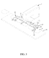
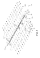
- a sewing machine feed mechanism 2 is used with a sewing machine 3 and mounted on a work table 30 of the sewing machine 3. On the work table 30, there are placed multiple pieces of fabrics 4 to be sewn. These fabrics 4 are sequentially moved into between the work table 30 and the feed mechanism 2 via a feed-in end 20 of the latter, and then horizontally transported to a stitch forming area of the sewing machine 3 for sewing. The sewn fabrics 4 form half-finished products, which are then output via a feed-out end 21 of the feed mechanism 2.
- the feed mechanism 2 of the present invention includes a first feed assembly 22 and a second feed assembly 23, and a driving motor 24 serving as a common driving source shared by the first and second feed assemblies 22, 23.
- first feed assembly 22 and the second feed mechanism 23 have an identical internal structure and are different from each other only in their lengths, in this specification, only the first feed assembly 22 is described in detail. Description of the second feed assembly 23 is omitted herein.
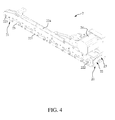
- the first feed assembly 22 includes a pair of side frames 221; two belt wheels 222, 223 mounted to between a front and a rear end of the pair of side frames 221, respectively; and a feed belt 224 fitted on around the two belt wheels 222, 223 to define an encircled space 225 having a predetermined vertical height.
- the belt wheel 222 located between the front end of the pair of side frames 221 forms the feed-in end 20 of the feed mechanism 2
- the belt wheel 223 located between the rear end of the pair of side frames 221 forms the feed-out end 21 of the feed mechanism 2.
- the two belt wheels 222, 223 are driven by the driving motor 24 to rotate, and accordingly, bring the feed belt 224 to rotate synchronously with them.
- An outer surface of the feed belt 224 is in compressive contact with the fabrics 4 located between the work table 30 and the feed mechanism 2, such that the feed belt 224 in rotating can bring the fabrics 4 to move along with it.
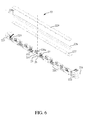
- the first feed assembly 22 further includes a plurality of pressing elements 226, which are located in the encircled space 225 at a lower portion thereof and are spaced from one another; a flexible supporting plate 227 located atop the pressing elements 226; an elongate airbag 228 located atop the flexible supporting plate 227; and a hold-down plate 229 located atop the airbag 228.
- the airbag 228 is provided with a valve 228a, which is in fluid communication with an air-pressure control device (not shown) located outside the feed mechanism 2. An internal pressure of the airbag 228 can be regulated via the air-pressure control device.
- the hold-down plate 229 is fixedly connected to the pair of side frames 221. When the airbag 228 is inflated and changes in volume, the hold-down plate 229 restricts the airbag 228 from expanding upward. That is, the airbag 228 can only expand downward and accordingly deforms the flexible supporting plate 227 located below the airbag 228. Meanwhile, the deformed supporting plate 227 generates a downward force against the pressing elements 226.
- the pressing elements 226 are respectively configured as a pressure-bearing roller unit. Every pressure-bearing roller unit 226 is located at a position that is height adjustable with changes of the internal pressure of the airbag 228. Further, a plurality of locating brackets 25 is mounted on the two side frames 221 at positions corresponding to the pressure-bearing roller units 226, so as to limit a range, within which the positional height of every pressure-bearing roller unit 226 is limited.
- the pressure-bearing roller unit includes two spaced rollers 226a, which respectively have an axially extended central through hole 226b and are in contact at a bottom with the feed belt 224.
- the side frames 221 are respectively provided at positions corresponding to the rollers 226a with a plurality of mounting holes 221a, and at positions immediately above the mounting holes 221 a with a plurality of locating holes 221b.
- the locating brackets 25 respectively include a connection section 251, which is located outside the side frames 221, and two laterally spaced lug sections 252 for correspondingly extending into two locating holes 221b.
- every connection section 251 is provided near two opposite ends with two fastening holes 253, which are located corresponding to the central through holes 226b of the rollers 226a.
- screws 26 are separately extended through the fastening holes 253 on the locating brackets 25 that are located outside one of the two side frames 221. Then, the screws 26 sequentially pass through the mounting holes 221a on the side frame 221, the central through holes 226b of the rollers 226a, and the mounting holes 221 a on the other side frame 221 to respectively expose a partial threaded length from the fastening holes 253 on the locating brackets 25 that are located outside the other side frame 221. Finally, nuts 27 are separately tightened to the exposed threaded lengths of the screws 26, so that the locating brackets 25, the side frames 221 and the pressing elements 226 are coupled to one another.
- the locating holes 221b on the side frames 221 are rectangular openings that provide spaces for the lug sections 252 of the locating brackets 25 to be movably set therein, such that the lug sections 252 set in the locating holes 221b together form a support means in the encircled space 225 to support the flexible supporting plate 227 thereon.
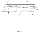
- Fig. 7 While the fabrics 4 having been fed into between the feed mechanism 2 and the work table 30 for sewing are brought by the feed belt 224 to horizontally move in a predetermined direction, the internal pressure of the airbag 228 can be regulated for the feed mechanism 2 to distribute even pressure on the fabrics 4 in compliance with the specific thickness and the surface texture of the fabrics 4.
Landscapes
- Engineering & Computer Science (AREA)
- Textile Engineering (AREA)
- Sewing Machines And Sewing (AREA)
Applications Claiming Priority (1)
| Application Number | Priority Date | Filing Date | Title |
|---|---|---|---|
| TW102130162A TWI468568B (zh) | 2013-08-23 | 2013-08-23 | The conveyor of the sewing machine |
Publications (2)
| Publication Number | Publication Date |
|---|---|
| EP2840176A1 true EP2840176A1 (de) | 2015-02-25 |
| EP2840176B1 EP2840176B1 (de) | 2016-08-24 |
Family
ID=50927992
Family Applications (1)
| Application Number | Title | Priority Date | Filing Date |
|---|---|---|---|
| EP14172009.4A Not-in-force EP2840176B1 (de) | 2013-08-23 | 2014-06-11 | Nähmaschinenzuführmechanismus |
Country Status (6)
| Country | Link |
|---|---|
| US (1) | US8919269B1 (de) |
| EP (1) | EP2840176B1 (de) |
| JP (1) | JP5878206B2 (de) |
| KR (1) | KR101589236B1 (de) |
| BR (1) | BR102014013621A2 (de) |
| TW (1) | TWI468568B (de) |
Cited By (2)
| Publication number | Priority date | Publication date | Assignee | Title |
|---|---|---|---|---|
| CN107503048A (zh) * | 2017-08-28 | 2017-12-22 | 杰克缝纫机股份有限公司 | 一种自动缝纫设备的缝料弧边控制装置及自动缝纫设备 |
| CN110130005A (zh) * | 2018-06-26 | 2019-08-16 | 双日株式会社 | 缝制装置 |
Families Citing this family (11)
| Publication number | Priority date | Publication date | Assignee | Title |
|---|---|---|---|---|
| KR101701196B1 (ko) * | 2015-07-29 | 2017-02-02 | 주식회사 아이피글로벌 | 차량용 시트 봉제시 테두리 마감용 원단 공급장치 |
| JP6653600B2 (ja) * | 2016-03-10 | 2020-02-26 | 蛇の目ミシン工業株式会社 | ミシン |
| CN107723931A (zh) * | 2017-11-14 | 2018-02-23 | 东莞奎克自动化设备有限公司 | 三文治式上下同步传动缝纫装置 |
| CN109680416B (zh) * | 2019-01-21 | 2024-03-12 | 苏州大喆智能科技有限公司 | 一种双侧同步带输送运动机构 |
| CN109667070A (zh) * | 2019-02-27 | 2019-04-23 | 杰克缝纫机股份有限公司 | 一种锁眼机 |
| CN110067088B (zh) * | 2019-05-15 | 2021-04-06 | 陈建强 | 一种自动毛巾连续锁边装置及其锁边方法 |
| US10889929B1 (en) * | 2020-07-01 | 2021-01-12 | Softwear Automation, Inc. | Adaptive apparatus for transporting and sewing material along arbitrary seam shapes |
| US11499257B2 (en) | 2020-08-04 | 2022-11-15 | Softwear Automation, Inc. | Material aligner |
| US10988880B1 (en) * | 2020-08-04 | 2021-04-27 | Softwear Automation, Inc. | Material aligner |
| CN115467101B (zh) * | 2022-09-19 | 2023-09-15 | 泉州市弘扬精密机械有限公司 | 一种针织织物的针织设备 |
| CN115584601A (zh) * | 2022-10-12 | 2023-01-10 | 江苏麦信环能科技有限公司 | 一种布料自动缝边设备 |
Citations (5)
| Publication number | Priority date | Publication date | Assignee | Title |
|---|---|---|---|---|
| EP0010703A2 (de) * | 1978-11-06 | 1980-05-14 | Dürkoppwerke Gmbh | Nähmaschine mit kontinuierlich angetriebenen endlosen Stoffschiebern |
| US4417535A (en) * | 1980-12-19 | 1983-11-29 | Durkoppwerke Gmbh | Sewing machine belt feeder with tensioner |
| US4813364A (en) * | 1988-04-08 | 1989-03-21 | Boser Ronald J | Belt drive material feed control apparatus for sewing machines |
| CN201317583Y (zh) * | 2008-11-10 | 2009-09-30 | 上海高罗输送装备有限公司 | 用于输送带清扫装置的气囊式张紧器 |
| JP2009256048A (ja) * | 2008-04-16 | 2009-11-05 | Tsubakimoto Chain Co | 摩擦駆動式ワーク搬送システム |
Family Cites Families (23)
| Publication number | Priority date | Publication date | Assignee | Title |
|---|---|---|---|---|
| US2241230A (en) * | 1937-07-07 | 1941-05-06 | Union Special Machine Co | Sewing machine |
| US3800719A (en) * | 1972-09-08 | 1974-04-02 | Jetsew Inc | Sewing machine material feed mechanism |
| US4462530A (en) * | 1977-02-25 | 1984-07-31 | Joseph Galkin Corporation | High speed indexing system |
| FR2498211A1 (fr) * | 1981-01-16 | 1982-07-23 | Inst Textile De France | Procede et dispositif de traitement de pieces de tissu rectangulaires |
| US4457243A (en) * | 1982-02-04 | 1984-07-03 | The Charles Stark Draper Laboratory, Inc. | Automated seam joining apparatus |
| US4512269A (en) * | 1983-07-19 | 1985-04-23 | The Charles Stark Draper Laboratory, Inc. | Automated assembly system for seamed articles |
| US4632046A (en) * | 1984-03-08 | 1986-12-30 | The Charles Stark Draper Laboratory, Inc. | Assembly system for seamed articles |
| DE3710025A1 (de) * | 1987-03-27 | 1988-10-13 | Schmale Carl Gmbh & Co Kg | Verfahren und vorrichtung zur vollautomatischen herstellung von an ihren raendern eingefassten textilerzeugnissen |
| US4719864A (en) * | 1987-05-11 | 1988-01-19 | The Charles Stark Draper Laboratory, Inc. | Limp material seam joining apparatus with rotatable limp material feed assembly |
| US4972787A (en) * | 1988-03-02 | 1990-11-27 | Union Special Corporation | Hemmer seamer assembly |
| US4922842A (en) * | 1988-03-02 | 1990-05-08 | Union Special Corporation | Hemmer seamer assembly |
| DE3810132C1 (de) * | 1988-03-25 | 1989-09-28 | Pfaff Ind Masch | Vorschubeinrichtung für flexible Werkstücke |
| DE3843000A1 (de) * | 1988-04-19 | 1989-11-02 | Continental Ag | Vorrichtung zur bereichsweisen festspannung eines biegeschlaffen, flaechigen materials |
| JPH0780174A (ja) * | 1993-09-10 | 1995-03-28 | Singer Nikko Kk | マスクの縫製装置 |
| US5410975A (en) * | 1993-12-15 | 1995-05-02 | Ykk Corporation | Apparatus for sewing fabric pieces to slide fastener chain |
| US5505406A (en) * | 1994-04-04 | 1996-04-09 | Alexander Machinery, Inc. | Apparatus and method for positioning a web roll |
| US5461999A (en) * | 1994-04-06 | 1995-10-31 | Marcangelo; Steven | Edge guiding apparatus for sewing machines |
| AT404603B (de) * | 1996-10-04 | 1999-01-25 | Naehtechnik Sahl Ges M B H | Antriebsvorrichtung für eine intermittierende förderbewegung |
| US6123039A (en) * | 1999-12-07 | 2000-09-26 | Yugen Kaisha Niiken Kogyosho | Endless-belt type walking presser foot |
| CN1956899B (zh) * | 2004-05-21 | 2011-05-04 | 大日本印刷株式会社 | 基板收纳容器、基板收纳体及基板输送装置 |
| CN100596288C (zh) * | 2007-05-16 | 2010-03-31 | 上海工程技术大学 | 爬线机器人 |
| KR100888940B1 (ko) | 2008-12-30 | 2009-03-17 | 조세제 | 재봉기용 재봉물 이송장치 |
| IT1396836B1 (it) * | 2009-11-19 | 2012-12-14 | Vi Be Mac Spa | Dispositivo trasportatore e macchina da cucire comprendente tale dispositivo. |
-
2013
- 2013-08-23 TW TW102130162A patent/TWI468568B/zh not_active IP Right Cessation
-
2014
- 2014-05-15 US US14/277,952 patent/US8919269B1/en not_active Expired - Fee Related
- 2014-05-22 KR KR1020140061672A patent/KR101589236B1/ko not_active Expired - Fee Related
- 2014-05-26 JP JP2014108321A patent/JP5878206B2/ja not_active Expired - Fee Related
- 2014-06-05 BR BR102014013621A patent/BR102014013621A2/pt not_active IP Right Cessation
- 2014-06-11 EP EP14172009.4A patent/EP2840176B1/de not_active Not-in-force
Patent Citations (5)
| Publication number | Priority date | Publication date | Assignee | Title |
|---|---|---|---|---|
| EP0010703A2 (de) * | 1978-11-06 | 1980-05-14 | Dürkoppwerke Gmbh | Nähmaschine mit kontinuierlich angetriebenen endlosen Stoffschiebern |
| US4417535A (en) * | 1980-12-19 | 1983-11-29 | Durkoppwerke Gmbh | Sewing machine belt feeder with tensioner |
| US4813364A (en) * | 1988-04-08 | 1989-03-21 | Boser Ronald J | Belt drive material feed control apparatus for sewing machines |
| JP2009256048A (ja) * | 2008-04-16 | 2009-11-05 | Tsubakimoto Chain Co | 摩擦駆動式ワーク搬送システム |
| CN201317583Y (zh) * | 2008-11-10 | 2009-09-30 | 上海高罗输送装备有限公司 | 用于输送带清扫装置的气囊式张紧器 |
Cited By (4)
| Publication number | Priority date | Publication date | Assignee | Title |
|---|---|---|---|---|
| CN107503048A (zh) * | 2017-08-28 | 2017-12-22 | 杰克缝纫机股份有限公司 | 一种自动缝纫设备的缝料弧边控制装置及自动缝纫设备 |
| CN107503048B (zh) * | 2017-08-28 | 2020-09-04 | 杰克缝纫机股份有限公司 | 一种自动缝纫设备的缝料弧边控制装置及自动缝纫设备 |
| CN110130005A (zh) * | 2018-06-26 | 2019-08-16 | 双日株式会社 | 缝制装置 |
| CN110130005B (zh) * | 2018-06-26 | 2020-05-08 | 双日株式会社 | 缝制装置 |
Also Published As
| Publication number | Publication date |
|---|---|
| TW201508121A (zh) | 2015-03-01 |
| US8919269B1 (en) | 2014-12-30 |
| KR20150022642A (ko) | 2015-03-04 |
| JP2015039629A (ja) | 2015-03-02 |
| TWI468568B (zh) | 2015-01-11 |
| KR101589236B1 (ko) | 2016-01-27 |
| JP5878206B2 (ja) | 2016-03-08 |
| EP2840176B1 (de) | 2016-08-24 |
| BR102014013621A2 (pt) | 2015-10-13 |
Similar Documents
| Publication | Publication Date | Title |
|---|---|---|
| US8919269B1 (en) | Sewing machine feed mechanism | |
| CN205466058U (zh) | 一种柔性工装 | |
| CN104889691B (zh) | 冲压焊接生产线 | |
| JP6779066B2 (ja) | 搬送ベルトの装着方法 | |
| CN103015056A (zh) | 全自动松紧带接缝机 | |
| CN109863013A (zh) | 膜施加装置以及膜施加方法 | |
| CN205294358U (zh) | 印刷设备的送纸结构 | |
| KR20210123115A (ko) | 흡착위치 및 크기조절가변이 가능한 디스플레이 패널 흡착장치 | |
| CN104097062B (zh) | 汽车后下摆臂轴套和端板压装设备 | |
| CN108466484A (zh) | 数码印刷机 | |
| CN203902961U (zh) | 商标压紧装置 | |
| KR101589593B1 (ko) | 원단롤 측정 제어장치 | |
| CN205733639U (zh) | 一种可调节间距的钢制烘缸圆筒体的焊接滚轮架 | |
| KR101329214B1 (ko) | 타이어 반제품 제조용 비드포머장치 | |
| CN106734406A (zh) | 一种双滚动式u形折弯装置 | |
| CN106626336B (zh) | 注塑件折弯机构 | |
| CN204382774U (zh) | 一种纸箱印刷机辊压调整机构 | |
| KR20120021038A (ko) | 시트폴딩장치 | |
| CN104420077A (zh) | 缝纫机的传送装置 | |
| CN106183582A (zh) | 一种异型压花机 | |
| CN208930822U (zh) | 双套袋折边装置 | |
| TWM472065U (zh) | 縫紉機的傳送裝置 | |
| CN203429385U (zh) | 缝纫机的传送装置 | |
| KR101855309B1 (ko) | 프레스기에의 소재공급장치의 소재 평탄화 장치 | |
| KR101926733B1 (ko) | 탄소섬유 공급설비용 탄소섬유 피딩장치 |
Legal Events
| Date | Code | Title | Description |
|---|---|---|---|
| PUAI | Public reference made under article 153(3) epc to a published international application that has entered the european phase |
Free format text: ORIGINAL CODE: 0009012 |
|
| 17P | Request for examination filed |
Effective date: 20140708 |
|
| AK | Designated contracting states |
Kind code of ref document: A1 Designated state(s): AL AT BE BG CH CY CZ DE DK EE ES FI FR GB GR HR HU IE IS IT LI LT LU LV MC MK MT NL NO PL PT RO RS SE SI SK SM TR |
|
| AX | Request for extension of the european patent |
Extension state: BA ME |
|
| RIN1 | Information on inventor provided before grant (corrected) |
Inventor name: CHEN, MAN CHUING |
|
| GRAP | Despatch of communication of intention to grant a patent |
Free format text: ORIGINAL CODE: EPIDOSNIGR1 |
|
| INTG | Intention to grant announced |
Effective date: 20160310 |
|
| GRAS | Grant fee paid |
Free format text: ORIGINAL CODE: EPIDOSNIGR3 |
|
| GRAA | (expected) grant |
Free format text: ORIGINAL CODE: 0009210 |
|
| AK | Designated contracting states |
Kind code of ref document: B1 Designated state(s): AL AT BE BG CH CY CZ DE DK EE ES FI FR GB GR HR HU IE IS IT LI LT LU LV MC MK MT NL NO PL PT RO RS SE SI SK SM TR |
|
| REG | Reference to a national code |
Ref country code: GB Ref legal event code: FG4D |
|
| REG | Reference to a national code |
Ref country code: CH Ref legal event code: EP |
|
| REG | Reference to a national code |
Ref country code: AT Ref legal event code: REF Ref document number: 823197 Country of ref document: AT Kind code of ref document: T Effective date: 20160915 |
|
| REG | Reference to a national code |
Ref country code: IE Ref legal event code: FG4D |
|
| REG | Reference to a national code |
Ref country code: DE Ref legal event code: R096 Ref document number: 602014003200 Country of ref document: DE |
|
| REG | Reference to a national code |
Ref country code: LT Ref legal event code: MG4D |
|
| REG | Reference to a national code |
Ref country code: NL Ref legal event code: MP Effective date: 20160824 |
|
| REG | Reference to a national code |
Ref country code: AT Ref legal event code: MK05 Ref document number: 823197 Country of ref document: AT Kind code of ref document: T Effective date: 20160824 |
|
| PG25 | Lapsed in a contracting state [announced via postgrant information from national office to epo] |
Ref country code: RS Free format text: LAPSE BECAUSE OF FAILURE TO SUBMIT A TRANSLATION OF THE DESCRIPTION OR TO PAY THE FEE WITHIN THE PRESCRIBED TIME-LIMIT Effective date: 20160824 Ref country code: NO Free format text: LAPSE BECAUSE OF FAILURE TO SUBMIT A TRANSLATION OF THE DESCRIPTION OR TO PAY THE FEE WITHIN THE PRESCRIBED TIME-LIMIT Effective date: 20161124 Ref country code: HR Free format text: LAPSE BECAUSE OF FAILURE TO SUBMIT A TRANSLATION OF THE DESCRIPTION OR TO PAY THE FEE WITHIN THE PRESCRIBED TIME-LIMIT Effective date: 20160824 Ref country code: LT Free format text: LAPSE BECAUSE OF FAILURE TO SUBMIT A TRANSLATION OF THE DESCRIPTION OR TO PAY THE FEE WITHIN THE PRESCRIBED TIME-LIMIT Effective date: 20160824 Ref country code: FI Free format text: LAPSE BECAUSE OF FAILURE TO SUBMIT A TRANSLATION OF THE DESCRIPTION OR TO PAY THE FEE WITHIN THE PRESCRIBED TIME-LIMIT Effective date: 20160824 Ref country code: NL Free format text: LAPSE BECAUSE OF FAILURE TO SUBMIT A TRANSLATION OF THE DESCRIPTION OR TO PAY THE FEE WITHIN THE PRESCRIBED TIME-LIMIT Effective date: 20160824 |
|
| PG25 | Lapsed in a contracting state [announced via postgrant information from national office to epo] |
Ref country code: SE Free format text: LAPSE BECAUSE OF FAILURE TO SUBMIT A TRANSLATION OF THE DESCRIPTION OR TO PAY THE FEE WITHIN THE PRESCRIBED TIME-LIMIT Effective date: 20160824 Ref country code: LV Free format text: LAPSE BECAUSE OF FAILURE TO SUBMIT A TRANSLATION OF THE DESCRIPTION OR TO PAY THE FEE WITHIN THE PRESCRIBED TIME-LIMIT Effective date: 20160824 Ref country code: GR Free format text: LAPSE BECAUSE OF FAILURE TO SUBMIT A TRANSLATION OF THE DESCRIPTION OR TO PAY THE FEE WITHIN THE PRESCRIBED TIME-LIMIT Effective date: 20161125 Ref country code: AT Free format text: LAPSE BECAUSE OF FAILURE TO SUBMIT A TRANSLATION OF THE DESCRIPTION OR TO PAY THE FEE WITHIN THE PRESCRIBED TIME-LIMIT Effective date: 20160824 Ref country code: ES Free format text: LAPSE BECAUSE OF FAILURE TO SUBMIT A TRANSLATION OF THE DESCRIPTION OR TO PAY THE FEE WITHIN THE PRESCRIBED TIME-LIMIT Effective date: 20160824 Ref country code: PT Free format text: LAPSE BECAUSE OF FAILURE TO SUBMIT A TRANSLATION OF THE DESCRIPTION OR TO PAY THE FEE WITHIN THE PRESCRIBED TIME-LIMIT Effective date: 20161226 |
|
| PG25 | Lapsed in a contracting state [announced via postgrant information from national office to epo] |
Ref country code: EE Free format text: LAPSE BECAUSE OF FAILURE TO SUBMIT A TRANSLATION OF THE DESCRIPTION OR TO PAY THE FEE WITHIN THE PRESCRIBED TIME-LIMIT Effective date: 20160824 Ref country code: RO Free format text: LAPSE BECAUSE OF FAILURE TO SUBMIT A TRANSLATION OF THE DESCRIPTION OR TO PAY THE FEE WITHIN THE PRESCRIBED TIME-LIMIT Effective date: 20160824 |
|
| REG | Reference to a national code |
Ref country code: DE Ref legal event code: R097 Ref document number: 602014003200 Country of ref document: DE |
|
| PG25 | Lapsed in a contracting state [announced via postgrant information from national office to epo] |
Ref country code: CZ Free format text: LAPSE BECAUSE OF FAILURE TO SUBMIT A TRANSLATION OF THE DESCRIPTION OR TO PAY THE FEE WITHIN THE PRESCRIBED TIME-LIMIT Effective date: 20160824 Ref country code: PL Free format text: LAPSE BECAUSE OF FAILURE TO SUBMIT A TRANSLATION OF THE DESCRIPTION OR TO PAY THE FEE WITHIN THE PRESCRIBED TIME-LIMIT Effective date: 20160824 Ref country code: DK Free format text: LAPSE BECAUSE OF FAILURE TO SUBMIT A TRANSLATION OF THE DESCRIPTION OR TO PAY THE FEE WITHIN THE PRESCRIBED TIME-LIMIT Effective date: 20160824 Ref country code: BG Free format text: LAPSE BECAUSE OF FAILURE TO SUBMIT A TRANSLATION OF THE DESCRIPTION OR TO PAY THE FEE WITHIN THE PRESCRIBED TIME-LIMIT Effective date: 20161124 Ref country code: SK Free format text: LAPSE BECAUSE OF FAILURE TO SUBMIT A TRANSLATION OF THE DESCRIPTION OR TO PAY THE FEE WITHIN THE PRESCRIBED TIME-LIMIT Effective date: 20160824 Ref country code: BE Free format text: LAPSE BECAUSE OF FAILURE TO SUBMIT A TRANSLATION OF THE DESCRIPTION OR TO PAY THE FEE WITHIN THE PRESCRIBED TIME-LIMIT Effective date: 20160824 Ref country code: SM Free format text: LAPSE BECAUSE OF FAILURE TO SUBMIT A TRANSLATION OF THE DESCRIPTION OR TO PAY THE FEE WITHIN THE PRESCRIBED TIME-LIMIT Effective date: 20160824 |
|
| PLBE | No opposition filed within time limit |
Free format text: ORIGINAL CODE: 0009261 |
|
| STAA | Information on the status of an ep patent application or granted ep patent |
Free format text: STATUS: NO OPPOSITION FILED WITHIN TIME LIMIT |
|
| 26N | No opposition filed |
Effective date: 20170526 |
|
| PG25 | Lapsed in a contracting state [announced via postgrant information from national office to epo] |
Ref country code: SI Free format text: LAPSE BECAUSE OF FAILURE TO SUBMIT A TRANSLATION OF THE DESCRIPTION OR TO PAY THE FEE WITHIN THE PRESCRIBED TIME-LIMIT Effective date: 20160824 |
|
| PGFP | Annual fee paid to national office [announced via postgrant information from national office to epo] |
Ref country code: IT Payment date: 20170630 Year of fee payment: 4 |
|
| PGFP | Annual fee paid to national office [announced via postgrant information from national office to epo] |
Ref country code: DE Payment date: 20170628 Year of fee payment: 4 |
|
| PG25 | Lapsed in a contracting state [announced via postgrant information from national office to epo] |
Ref country code: MC Free format text: LAPSE BECAUSE OF FAILURE TO SUBMIT A TRANSLATION OF THE DESCRIPTION OR TO PAY THE FEE WITHIN THE PRESCRIBED TIME-LIMIT Effective date: 20160824 |
|
| REG | Reference to a national code |
Ref country code: CH Ref legal event code: PL |
|
| REG | Reference to a national code |
Ref country code: IE Ref legal event code: MM4A |
|
| REG | Reference to a national code |
Ref country code: FR Ref legal event code: ST Effective date: 20180228 |
|
| PG25 | Lapsed in a contracting state [announced via postgrant information from national office to epo] |
Ref country code: LU Free format text: LAPSE BECAUSE OF NON-PAYMENT OF DUE FEES Effective date: 20170611 Ref country code: LI Free format text: LAPSE BECAUSE OF NON-PAYMENT OF DUE FEES Effective date: 20170630 Ref country code: CH Free format text: LAPSE BECAUSE OF NON-PAYMENT OF DUE FEES Effective date: 20170630 Ref country code: IE Free format text: LAPSE BECAUSE OF NON-PAYMENT OF DUE FEES Effective date: 20170611 |
|
| PG25 | Lapsed in a contracting state [announced via postgrant information from national office to epo] |
Ref country code: FR Free format text: LAPSE BECAUSE OF NON-PAYMENT OF DUE FEES Effective date: 20170630 |
|
| PG25 | Lapsed in a contracting state [announced via postgrant information from national office to epo] |
Ref country code: MT Free format text: LAPSE BECAUSE OF NON-PAYMENT OF DUE FEES Effective date: 20170611 |
|
| PG25 | Lapsed in a contracting state [announced via postgrant information from national office to epo] |
Ref country code: AL Free format text: LAPSE BECAUSE OF FAILURE TO SUBMIT A TRANSLATION OF THE DESCRIPTION OR TO PAY THE FEE WITHIN THE PRESCRIBED TIME-LIMIT Effective date: 20160824 |
|
| REG | Reference to a national code |
Ref country code: DE Ref legal event code: R119 Ref document number: 602014003200 Country of ref document: DE |
|
| GBPC | Gb: european patent ceased through non-payment of renewal fee |
Effective date: 20180611 |
|
| PG25 | Lapsed in a contracting state [announced via postgrant information from national office to epo] |
Ref country code: IT Free format text: LAPSE BECAUSE OF NON-PAYMENT OF DUE FEES Effective date: 20180611 Ref country code: DE Free format text: LAPSE BECAUSE OF NON-PAYMENT OF DUE FEES Effective date: 20190101 Ref country code: GB Free format text: LAPSE BECAUSE OF NON-PAYMENT OF DUE FEES Effective date: 20180611 |
|
| PG25 | Lapsed in a contracting state [announced via postgrant information from national office to epo] |
Ref country code: HU Free format text: LAPSE BECAUSE OF FAILURE TO SUBMIT A TRANSLATION OF THE DESCRIPTION OR TO PAY THE FEE WITHIN THE PRESCRIBED TIME-LIMIT; INVALID AB INITIO Effective date: 20140611 |
|
| PG25 | Lapsed in a contracting state [announced via postgrant information from national office to epo] |
Ref country code: CY Free format text: LAPSE BECAUSE OF FAILURE TO SUBMIT A TRANSLATION OF THE DESCRIPTION OR TO PAY THE FEE WITHIN THE PRESCRIBED TIME-LIMIT Effective date: 20160824 |
|
| PG25 | Lapsed in a contracting state [announced via postgrant information from national office to epo] |
Ref country code: MK Free format text: LAPSE BECAUSE OF FAILURE TO SUBMIT A TRANSLATION OF THE DESCRIPTION OR TO PAY THE FEE WITHIN THE PRESCRIBED TIME-LIMIT Effective date: 20160824 |
|
| PG25 | Lapsed in a contracting state [announced via postgrant information from national office to epo] |
Ref country code: TR Free format text: LAPSE BECAUSE OF FAILURE TO SUBMIT A TRANSLATION OF THE DESCRIPTION OR TO PAY THE FEE WITHIN THE PRESCRIBED TIME-LIMIT Effective date: 20160824 |
|
| PG25 | Lapsed in a contracting state [announced via postgrant information from national office to epo] |
Ref country code: IS Free format text: LAPSE BECAUSE OF FAILURE TO SUBMIT A TRANSLATION OF THE DESCRIPTION OR TO PAY THE FEE WITHIN THE PRESCRIBED TIME-LIMIT Effective date: 20161224 |