EP2827975B1 - System und verfahren zum anfahren von rührwerken in einem sediment - Google Patents
System und verfahren zum anfahren von rührwerken in einem sediment Download PDFInfo
- Publication number
- EP2827975B1 EP2827975B1 EP13717159.1A EP13717159A EP2827975B1 EP 2827975 B1 EP2827975 B1 EP 2827975B1 EP 13717159 A EP13717159 A EP 13717159A EP 2827975 B1 EP2827975 B1 EP 2827975B1
- Authority
- EP
- European Patent Office
- Prior art keywords
- purging
- stirring
- pump
- sediment
- medium
- Prior art date
- Legal status (The legal status is an assumption and is not a legal conclusion. Google has not performed a legal analysis and makes no representation as to the accuracy of the status listed.)
- Not-in-force
Links
- 239000013049 sediment Substances 0.000 title claims description 58
- 238000003756 stirring Methods 0.000 title claims description 45
- 238000000034 method Methods 0.000 title claims description 12
- 238000010926 purge Methods 0.000 claims description 48
- 239000007787 solid Substances 0.000 claims description 13
- 238000004062 sedimentation Methods 0.000 claims description 11
- 239000000725 suspension Substances 0.000 claims description 9
- 239000000463 material Substances 0.000 claims description 7
- 238000005243 fluidization Methods 0.000 claims description 5
- 238000005259 measurement Methods 0.000 claims description 3
- 238000012544 monitoring process Methods 0.000 claims description 3
- 230000015556 catabolic process Effects 0.000 claims description 2
- 238000011010 flushing procedure Methods 0.000 description 25
- 239000007788 liquid Substances 0.000 description 15
- 239000000126 substance Substances 0.000 description 3
- 238000005273 aeration Methods 0.000 description 2
- 238000005452 bending Methods 0.000 description 2
- 238000005516 engineering process Methods 0.000 description 2
- 230000002378 acidificating effect Effects 0.000 description 1
- 238000013459 approach Methods 0.000 description 1
- 230000008901 benefit Effects 0.000 description 1
- 230000001419 dependent effect Effects 0.000 description 1
- 238000013461 design Methods 0.000 description 1
- 238000011161 development Methods 0.000 description 1
- 230000018109 developmental process Effects 0.000 description 1
- 230000000694 effects Effects 0.000 description 1
- 230000005611 electricity Effects 0.000 description 1
- 239000012530 fluid Substances 0.000 description 1
- 230000007257 malfunction Effects 0.000 description 1
- 210000000056 organ Anatomy 0.000 description 1
- 239000002245 particle Substances 0.000 description 1
- 230000008569 process Effects 0.000 description 1
- 238000012545 processing Methods 0.000 description 1
- 230000009467 reduction Effects 0.000 description 1
- 230000004044 response Effects 0.000 description 1
- 239000002002 slurry Substances 0.000 description 1
- 230000007480 spreading Effects 0.000 description 1
Images


Classifications
-
- B—PERFORMING OPERATIONS; TRANSPORTING
- B01—PHYSICAL OR CHEMICAL PROCESSES OR APPARATUS IN GENERAL
- B01F—MIXING, e.g. DISSOLVING, EMULSIFYING OR DISPERSING
- B01F23/00—Mixing according to the phases to be mixed, e.g. dispersing or emulsifying
- B01F23/50—Mixing liquids with solids
-
- B—PERFORMING OPERATIONS; TRANSPORTING
- B08—CLEANING
- B08B—CLEANING IN GENERAL; PREVENTION OF FOULING IN GENERAL
- B08B9/00—Cleaning hollow articles by methods or apparatus specially adapted thereto
- B08B9/08—Cleaning containers, e.g. tanks
- B08B9/093—Cleaning containers, e.g. tanks by the force of jets or sprays
- B08B9/0933—Removing sludge or the like from tank bottoms
-
- B—PERFORMING OPERATIONS; TRANSPORTING
- B01—PHYSICAL OR CHEMICAL PROCESSES OR APPARATUS IN GENERAL
- B01F—MIXING, e.g. DISSOLVING, EMULSIFYING OR DISPERSING
- B01F23/00—Mixing according to the phases to be mixed, e.g. dispersing or emulsifying
- B01F23/02—Maintaining the aggregation state of the mixed materials
- B01F23/023—Preventing sedimentation, conglomeration or agglomeration of solid ingredients during or after mixing by maintaining mixed ingredients in movement
-
- B—PERFORMING OPERATIONS; TRANSPORTING
- B01—PHYSICAL OR CHEMICAL PROCESSES OR APPARATUS IN GENERAL
- B01F—MIXING, e.g. DISSOLVING, EMULSIFYING OR DISPERSING
- B01F23/00—Mixing according to the phases to be mixed, e.g. dispersing or emulsifying
- B01F23/50—Mixing liquids with solids
- B01F23/53—Mixing liquids with solids using driven stirrers
-
- B—PERFORMING OPERATIONS; TRANSPORTING
- B01—PHYSICAL OR CHEMICAL PROCESSES OR APPARATUS IN GENERAL
- B01F—MIXING, e.g. DISSOLVING, EMULSIFYING OR DISPERSING
- B01F27/00—Mixers with rotary stirring devices in fixed receptacles; Kneaders
- B01F27/05—Stirrers
- B01F27/11—Stirrers characterised by the configuration of the stirrers
- B01F27/112—Stirrers characterised by the configuration of the stirrers with arms, paddles, vanes or blades
- B01F27/1123—Stirrers characterised by the configuration of the stirrers with arms, paddles, vanes or blades sickle-shaped, i.e. curved in at least one direction
-
- B—PERFORMING OPERATIONS; TRANSPORTING
- B01—PHYSICAL OR CHEMICAL PROCESSES OR APPARATUS IN GENERAL
- B01F—MIXING, e.g. DISSOLVING, EMULSIFYING OR DISPERSING
- B01F27/00—Mixers with rotary stirring devices in fixed receptacles; Kneaders
- B01F27/05—Stirrers
- B01F27/11—Stirrers characterised by the configuration of the stirrers
- B01F27/112—Stirrers characterised by the configuration of the stirrers with arms, paddles, vanes or blades
- B01F27/1125—Stirrers characterised by the configuration of the stirrers with arms, paddles, vanes or blades with vanes or blades extending parallel or oblique to the stirrer axis
-
- B—PERFORMING OPERATIONS; TRANSPORTING
- B01—PHYSICAL OR CHEMICAL PROCESSES OR APPARATUS IN GENERAL
- B01F—MIXING, e.g. DISSOLVING, EMULSIFYING OR DISPERSING
- B01F27/00—Mixers with rotary stirring devices in fixed receptacles; Kneaders
- B01F27/05—Stirrers
- B01F27/11—Stirrers characterised by the configuration of the stirrers
- B01F27/19—Stirrers with two or more mixing elements mounted in sequence on the same axis
- B01F27/191—Stirrers with two or more mixing elements mounted in sequence on the same axis with similar elements
-
- B—PERFORMING OPERATIONS; TRANSPORTING
- B01—PHYSICAL OR CHEMICAL PROCESSES OR APPARATUS IN GENERAL
- B01F—MIXING, e.g. DISSOLVING, EMULSIFYING OR DISPERSING
- B01F27/00—Mixers with rotary stirring devices in fixed receptacles; Kneaders
- B01F27/80—Mixers with rotary stirring devices in fixed receptacles; Kneaders with stirrers rotating about a substantially vertical axis
- B01F27/90—Mixers with rotary stirring devices in fixed receptacles; Kneaders with stirrers rotating about a substantially vertical axis with paddles or arms
-
- B—PERFORMING OPERATIONS; TRANSPORTING
- B01—PHYSICAL OR CHEMICAL PROCESSES OR APPARATUS IN GENERAL
- B01F—MIXING, e.g. DISSOLVING, EMULSIFYING OR DISPERSING
- B01F27/00—Mixers with rotary stirring devices in fixed receptacles; Kneaders
- B01F27/80—Mixers with rotary stirring devices in fixed receptacles; Kneaders with stirrers rotating about a substantially vertical axis
- B01F27/90—Mixers with rotary stirring devices in fixed receptacles; Kneaders with stirrers rotating about a substantially vertical axis with paddles or arms
- B01F27/906—Mixers with rotary stirring devices in fixed receptacles; Kneaders with stirrers rotating about a substantially vertical axis with paddles or arms with fixed axis
-
- B—PERFORMING OPERATIONS; TRANSPORTING
- B01—PHYSICAL OR CHEMICAL PROCESSES OR APPARATUS IN GENERAL
- B01F—MIXING, e.g. DISSOLVING, EMULSIFYING OR DISPERSING
- B01F33/00—Other mixers; Mixing plants; Combinations of mixers
- B01F33/40—Mixers using gas or liquid agitation, e.g. with air supply tubes
- B01F33/402—Mixers using gas or liquid agitation, e.g. with air supply tubes comprising supplementary stirring elements
-
- B—PERFORMING OPERATIONS; TRANSPORTING
- B01—PHYSICAL OR CHEMICAL PROCESSES OR APPARATUS IN GENERAL
- B01F—MIXING, e.g. DISSOLVING, EMULSIFYING OR DISPERSING
- B01F33/00—Other mixers; Mixing plants; Combinations of mixers
- B01F33/40—Mixers using gas or liquid agitation, e.g. with air supply tubes
- B01F33/402—Mixers using gas or liquid agitation, e.g. with air supply tubes comprising supplementary stirring elements
- B01F33/4021—Mixers using gas or liquid agitation, e.g. with air supply tubes comprising supplementary stirring elements the gas being introduced through the shaft of the stirring element
-
- B—PERFORMING OPERATIONS; TRANSPORTING
- B01—PHYSICAL OR CHEMICAL PROCESSES OR APPARATUS IN GENERAL
- B01F—MIXING, e.g. DISSOLVING, EMULSIFYING OR DISPERSING
- B01F33/00—Other mixers; Mixing plants; Combinations of mixers
- B01F33/40—Mixers using gas or liquid agitation, e.g. with air supply tubes
- B01F33/406—Mixers using gas or liquid agitation, e.g. with air supply tubes in receptacles with gas supply only at the bottom
-
- B—PERFORMING OPERATIONS; TRANSPORTING
- B01—PHYSICAL OR CHEMICAL PROCESSES OR APPARATUS IN GENERAL
- B01F—MIXING, e.g. DISSOLVING, EMULSIFYING OR DISPERSING
- B01F35/00—Accessories for mixers; Auxiliary operations or auxiliary devices; Parts or details of general application
- B01F35/10—Maintenance of mixers
-
- B—PERFORMING OPERATIONS; TRANSPORTING
- B01—PHYSICAL OR CHEMICAL PROCESSES OR APPARATUS IN GENERAL
- B01F—MIXING, e.g. DISSOLVING, EMULSIFYING OR DISPERSING
- B01F35/00—Accessories for mixers; Auxiliary operations or auxiliary devices; Parts or details of general application
- B01F35/10—Maintenance of mixers
- B01F35/145—Washing or cleaning mixers not provided for in other groups in this subclass; Inhibiting build-up of material on machine parts using other means
- B01F35/1452—Washing or cleaning mixers not provided for in other groups in this subclass; Inhibiting build-up of material on machine parts using other means using fluids
-
- B—PERFORMING OPERATIONS; TRANSPORTING
- B01—PHYSICAL OR CHEMICAL PROCESSES OR APPARATUS IN GENERAL
- B01F—MIXING, e.g. DISSOLVING, EMULSIFYING OR DISPERSING
- B01F35/00—Accessories for mixers; Auxiliary operations or auxiliary devices; Parts or details of general application
- B01F35/10—Maintenance of mixers
- B01F35/145—Washing or cleaning mixers not provided for in other groups in this subclass; Inhibiting build-up of material on machine parts using other means
- B01F35/1452—Washing or cleaning mixers not provided for in other groups in this subclass; Inhibiting build-up of material on machine parts using other means using fluids
- B01F35/1453—Washing or cleaning mixers not provided for in other groups in this subclass; Inhibiting build-up of material on machine parts using other means using fluids by means of jets of fluid, e.g. air
-
- B—PERFORMING OPERATIONS; TRANSPORTING
- B01—PHYSICAL OR CHEMICAL PROCESSES OR APPARATUS IN GENERAL
- B01F—MIXING, e.g. DISSOLVING, EMULSIFYING OR DISPERSING
- B01F35/00—Accessories for mixers; Auxiliary operations or auxiliary devices; Parts or details of general application
- B01F35/20—Measuring; Control or regulation
- B01F35/21—Measuring
- B01F35/211—Measuring of the operational parameters
- B01F35/2112—Level of material in a container or the position or shape of the upper surface of the material
-
- B—PERFORMING OPERATIONS; TRANSPORTING
- B01—PHYSICAL OR CHEMICAL PROCESSES OR APPARATUS IN GENERAL
- B01F—MIXING, e.g. DISSOLVING, EMULSIFYING OR DISPERSING
- B01F35/00—Accessories for mixers; Auxiliary operations or auxiliary devices; Parts or details of general application
- B01F35/20—Measuring; Control or regulation
- B01F35/21—Measuring
- B01F35/211—Measuring of the operational parameters
- B01F35/2113—Pressure
-
- B—PERFORMING OPERATIONS; TRANSPORTING
- B01—PHYSICAL OR CHEMICAL PROCESSES OR APPARATUS IN GENERAL
- B01F—MIXING, e.g. DISSOLVING, EMULSIFYING OR DISPERSING
- B01F35/00—Accessories for mixers; Auxiliary operations or auxiliary devices; Parts or details of general application
- B01F35/30—Driving arrangements; Transmissions; Couplings; Brakes
- B01F35/32—Driving arrangements
- B01F35/32005—Type of drive
- B01F35/3204—Motor driven, i.e. by means of an electric or IC motor
-
- B—PERFORMING OPERATIONS; TRANSPORTING
- B01—PHYSICAL OR CHEMICAL PROCESSES OR APPARATUS IN GENERAL
- B01F—MIXING, e.g. DISSOLVING, EMULSIFYING OR DISPERSING
- B01F35/00—Accessories for mixers; Auxiliary operations or auxiliary devices; Parts or details of general application
- B01F35/60—Safety arrangements
- B01F35/605—Safety devices concerning the operation of the mixer
-
- B—PERFORMING OPERATIONS; TRANSPORTING
- B01—PHYSICAL OR CHEMICAL PROCESSES OR APPARATUS IN GENERAL
- B01F—MIXING, e.g. DISSOLVING, EMULSIFYING OR DISPERSING
- B01F23/00—Mixing according to the phases to be mixed, e.g. dispersing or emulsifying
- B01F23/50—Mixing liquids with solids
- B01F23/58—Mixing liquids with solids characterised by the nature of the liquid
- B01F23/581—Mixing liquids with solids, slurries or sludge, for obtaining a diluted slurry
Definitions
- the present invention relates to a system and method for the controlled start-up of agitators in a sediment.
- One or more stirring devices can be operated simultaneously or alternately, so that there is no settling of solids.
- providing emergency generators for many large agitators is associated with high investment costs.
- An intermittent operation of several agitators offers the advantage that the emergency power supply can be made smaller, but has the disadvantage that the reconnection of an agitator only works when the settling times are sufficiently long. For example, it also forms for large containers with a filling height of 10 to 20 m and a high particle sinking speed of 1 to 10 cm / sec, the sediment can be harvested within a few to a few minutes.
- US 7,331,704 B2 describes a draft tube arrangement with a stirrer.
- the stirrer is arranged so that it is above the sediment in case of standstill.
- the guide tube is slotted at the bottom to allow easy flushing.
- DE 34 42 294 A1 describes a device for homogenizing and suspending solids in a pool.
- a pneumatic and / or hydraulic traction aid is provided, which facilitates sedimentation of the stirring blades in sedimented solids.
- the traction help consists of pumps and nozzles. It is described how by means of the pumps and the nozzles by sucking liquid from the upper region of a slurry and pushing this liquid through corresponding pipelines and pumps through the nozzles in the lower Beckeri Scheme or container area can be a loosening of the sediment and the agitator be driven only after sufficient loosening of the sediment.
- WO-A-2008/082339 discloses a system according to the preamble of claim 1 and a method according to the preamble of claim 14.
- the rinsing agent is liquid.
- the purging device in particular has a pump and supply lines through which the pump pumps the means for purging.
- the supply lines are in particular designed such that they lead the means for rinsing under or on the Rlickorgan romance. It is possible that as a rinsing agent liquid from the clear mirror is used, which is withdrawn from the pump and fed to the supply lines.
- the supply lines have in particular channels and outlets, which are part of the stirring organ leaves.
- a tubular stirrer which is connected to the supply lines and whose purge tubes are directed substantially parallel and in alignment with the stirrer blades to the outside, preferably sits on the shaft end below the free-to-tumble stirrer.
- the supply lines may also have free spouts, which are in such a defined position to the Rlickorgan carefuln that the means for rinsing enters the vicinity of the Rlickorgan stricture.
- the agitator preferably stops at a defined angular position with respect to the free spins.
- a wave catch ring is preferably provided, which supports the shaft bearing the Rhackorganence; to avoid mechanical bending of the shaft when starting, in which a maximum engine torque is required.
- the wave collecting ring is advantageously connected together with the free spins to a common, mechanically robust structure.
- the controller is provided with means for measuring a sedimentation level, ie a settled amount of solid, or a level of a clear mirror.
- the device for measuring measures a density or a pressure difference.
- the device for measuring can also be designed such that it calculates a settled amount of solids from physical values of the suspension by calculation.
- the agitator operating device preferably operates stirrers in response to the determined sedimentation level.
- the drive motor of the agitator is particularly frequency-controlled operable and the agitator is preferably ramped up via a ramp time.
- the system may comprise a plurality of agitators, wherein an emergency generator is provided which operates at least one of the agitators intermittently.
- the pump is preferably a circulation pump which circulates the purge means within the container while maintaining the existing pressure.
- the circulation pump is in particular a pump which is used in normal operation for conveying suspension.
- the purging pump is preferably put into operation a short time after a failure of agitators.
- an emergency generator is preferably provided which supplies power to the pump of the purging device.
- an intermediate container is preferably provided, which is arranged above a Sedimentations Ou and is filled if necessary by means of the pump with the means for rinsing, which is provided for brief flushing available.
- the device for operating stirrers is put into operation in particular with a time delay after a predetermined time for putting the flushing device into operation.
- the controller is also preferably provided with means for measuring pressure and / or volumetric flow in the supply lines to provide flushing results.
- An agitator is preferably restarted in accordance with the flushing results obtained by the means for measuring pressure and / or flow in the supply lines.
- a method according to claim 14 is carried out by means of a controller.
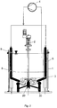
- FIGS. 1 . 4 and 5 each show an embodiment of a system for controlled start-up of agitators in a sediment according to the present invention.
- the system has in each case a container 1 for receiving substances to be processed, an agitator device with stirrer blades 3 for stirring the substances to be processed in the container 1, a purging device and a device 2 for operating agitators.
- the rinsing device is arranged and adapted to supply means for rinsing away the sediment to a sediment formed.
- the rinsing device has in particular one in the FIGS. 1 . 4 and 5 not shown pump 4 and at least one supply line 6, through which the pump 4 pumps the means for rinsing, on.
- the flushing device is designed in different ways as needed and will be explained in more detail with reference to the figures.
- a sediment height is denoted by 8 and a clear liquid level is denoted by 9.
- the flushing means is preferably liquid. It is possible that fluid from the clear mirror 9, which is drawn off from the pump 4 and supplied to the at least one supply line 6, is used as the means for rinsing free. When using the liquid above the sediment, ie from the clear mirror 9, a continuous rinsing is possible without the container 1 is overfilled.
- the device for measuring measures a density or a pressure difference.
- the device for measuring can also be designed such that it calculates a settled amount of solids from physical values of the suspension by calculation.
- the device 2 for operating agitators preferably puts stirrers into operation as a function of the determined sedimentation height 9.
- a drive motor of the agitator as a device 2 for operating agitators is in particular frequency-controlled operable and the agitator is preferably ramped up via a ramp time.
- the system may comprise a plurality of agitators, wherein preferably an emergency generator is provided, which operates at least one of the agitators intermittently.
- the purging pump 4 is preferably a circulation pump that circulates the purging means within the container 1 while maintaining the existing pressure.
- a circulation pump in particular a pump can be used, which is used in normal operation for conveying suspension.
- the pump 4 of the purging device is preferably put into operation shortly after a failure of agitators. It is particularly advantageous that in a pressurized container 1, the circulation pump does not have to build up the internal pressure, but only circulates the medium within the pressure chamber. In addition, it is advantageous if the pump 4 starts in case of failure of the agitator. The maximum time until the pump starts up should be such that the flushing holes are not yet covered with sediment when they are below the sediment.
- an emergency generator is preferably provided, which supplies power to the pump 4 of the purging device.
- an emergency generator for the pump 4 is sufficient, the connected load can be sized smaller by a factor of 2 to 10 than the power of the agitator motor 2.
- the fact that only the pump 4 of the purging device is to be supplied with power, thus becomes a Electricity required in the event of a breakdown reduced.
- an intermediate container 5 is preferably provided, which is arranged above a sedimentation level 8 and is filled by the pump 4 with the means for flushing if necessary and from which the means for rinsing then gradually or "suddenly "is led to the sediment.
- the device 2 for operating agitators i. the drive motor is put into operation, in particular, with a time delay after a predetermined time has elapsed after the purging device has been put into operation.
- means are preferably provided for measuring pressure and / or volumetric flow in the supply lines 6 to provide flushing results.
- An agitator is preferably in accordance with that of in the FIG. 3 shown control with 10 devices for measuring pressure p and / or flow in the at least one supply line 6 obtained results relating to the flushing again in operation.
- a large pump and possibly also a large intermediate container may be useful. It is sufficient to set the output in such a way that the flushing volume and the flushing pressure are sufficient to start the agitator. Once the agitator is running, you can (re) start the next agitator and so on, until all agitators run again.
- the at least one supply line 6 is in particular designed such that it leads the flushing means below or to the agitator blades 3.
- the at least one supply line 6 may have free spins which are in such a defined position to the agitator leaves 3, that the means for rinsing reaches the vicinity of the Rlickorganmind 3.
- the agitator preferably stops at a defined angular position with respect to the free spins.
- FIG. 1 two supply lines 6 are shown as free spouts into which the means for rinsing in the direction of the illustrated arrows by means of the pump of the rinsing device is introduced.
- the flushing means is then pumped through the free spins, which are first at the inner edge of the container 1 and then angled towards the Rrockorganmindn 3.
- the Rrockorganworkn 3 then exits the means for purging from the Frei Albanylanzen and serves there for purging the sediment, so that a start of the agitator is made possible in the sediment.
- FIG. 2 is that in FIG. 1 shown embodiment shown in more detail.
- the device 2 for operating the agitator, the agitator blades 3 and the supply lines 6 of the purging device, a pump 4 is shown, the liquid that removes the clear liquid level 9 and then the supply lines 6 supplies.
- FIG. 2 also a wave catch ring 20 is shown supporting the shaft bearing the agitator blades 3; to avoid mechanical bending of the shaft when starting, in which a maximum engine torque is required.
- the wave catching ring 20 is advantageously connected together with the free spreaders 6 to a common mechanically robust structure 30.
- FIG. 3 shows a more detailed illustration of in FIG. 1 illustrated embodiment.
- an intermediate container 5 is shown, in which the clear liquid level 9 pumped liquid can be stored until it is needed.
- Whether the liquid is needed is determined by a controller 10 including a measuring technique designated p for measuring pressure and / or volumetric flow in the at least one supply line 6 and measuring the level F of the intermediate container 5.
- a check valve 12 controlled by the controller 10 for controlling a flow of liquid from the surge tank 5 to the supply lines.
- the system for approaching agitators in the sediment can be configured flexibly and as needed.
- the pump 4, the intermediate container 5 and the controller 10 (with measuring technology, etc.) not only in the in FIG. 1 shown embodiment of the present invention are provided or can be provided, but that in the FIGS. 4 and 5 shown embodiments of the present invention with the pump 4, the intermediate container 5 and the controller 10 (with measurement technology, etc.) are equipped or can be equipped.
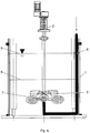
- a supply line 6 is shown as free spins, in which the means for rinsing in the direction of the arrow shown by means of the pump 4 of the rinsing device is introduced.
- the flushing means is then pumped through the free-spreader lance, which first extends at the inner edge of the container 1, angled at the bottom of the container towards the center of the container 1 and then angled in the center of the container 1 at its bottom in the upward direction and until just below the Rrockorganmind 3 runs.
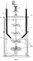
- FIG. 5 a system with several stirrers with stirrer blades 3 is shown. Of the four stirrers shown, two stirrers are shown in the sediment below the sediment level 8, and the other two stirrers are shown above the sediment but below the clear liquid level 9.
- a means for purging is supplied in the same manner, as already with reference to the FIG. 1 is described. Different from the FIG. 1 However, the means for purging of the two free spreading 6 is slightly above the Rrockorganmind 3 supplied.
- a pipe 11 is shown, which is supplied in the direction of darg Popeen arrow means for purging.
- the means for rinsing can of the in the FIG. 3 shown intermediate container, which is located above the agitator, are supplied.
- the tube 11 extends downwardly on the inner wall of the container 1 towards the bottom of the container 1, is angled slightly above the bottom towards the center of the container 1 and is angled in the center of the container in an upward direction to the center of the stirring member ,
- the means for purging is discharged into channels, which are located in the Rlickorganstoryn 3. From there, the means for purging is discharged through outlets on the stirrer blades 3 in the sediment.
- a flushing means is supplied to the sediment at two points, at which points there are stirring elements in the sediment.
- both stirring elements located in the sediment can be flushed out.
- 6 additional free spouts can be installed as supply lines.
- an already existing aeration system which is supplied with the means for flushing and serves for a short time as a flushing device.
- a method is carried out in which after detecting a failure of an agitator with agitator motor with concomitant sedimentation of recorded in the container to be processed substances, the lances are sporadically flushed in supply lines with the means for flushing.
- the sediment is fluidized by flushing with compressed air or the flushing means.
- the agitator is started up in reversing operation.
- the fluidization is stopped and the reversing operation is continued.
- the operation of the agitator is stopped briefly and the agitator motor is switched to the standard direction of rotation.
- the agitator is operated in normal operation.
- the operation of the stirrer in normal operation is carried out for a certain time while monitoring the operation by means of the controller and its facilities for measuring.
Landscapes
- Chemical & Material Sciences (AREA)
- Chemical Kinetics & Catalysis (AREA)
- Dispersion Chemistry (AREA)
- Engineering & Computer Science (AREA)
- Mechanical Engineering (AREA)
- Mixers Of The Rotary Stirring Type (AREA)
- Accessories For Mixers (AREA)
Description
- Die vorliegende Erfindung betrifft ein System und ein Verfahren zum gesteuerten Anfahren von Rührwerken in einem Sediment.
- Wenn ein Rührorgan in einem Sediment aus Feststoff sitzt, spricht man von "Anfahren in einem Sediment". Dieser Fall kann eintreten, wenn ein Rührwerk beim Verarbeiten von Suspensionen betriebsbedingt oder durch eine Störung, wie beispielsweise durch einen Stromausfall, stehen geblieben ist, ohne dass dies gewünscht ist. Der Feststoff sinkt im Behälter nach unten und bildet ein Sediment. Je nach Feststoffgehalt der Suspension und Position von Rührorganen überdeckt das Sediment das Rührorgan oder die Rührorgane. In Abhängigkeit von der Zeitdauer eines Stillstands verdichtet sich das Sediment nachträglich. Damit wird ein Anfahren nach dem Stillstand erschwert bis unmöglich.
- Zum Anfahren von Rührwerken in einem Sediment sind bislang folgende Vorschläge gemacht:
- Es wird versucht, Rührorgane oberhalb eines Sediments zu positionieren oder die Sedimenthöhe zu reduzieren, so dass die Rührorgane nicht im Sediment festsitzen. Jedoch ist es zum Erreichen eines zufriedenstellenden Rührens im Allgemeinen nötig, Rührorgane im unteren Drittel eines Behälters zu positionieren. Eine zu starke Abweichung von dieser Positionierung ist im Normalfall nicht zulässig, weil dies sonst die eigentliche Rühraufgabe "Suspendieren" ad absurdum führt. Ein Absenken der Sedimenthöhe würde für einen Anlagenbetreiber bedeuten, dass er weniger Material oder eine Suspension mit geringerem Feststoffanteil verarbeiten muss, was betriebswirtschaftlich keinen Sinn macht.
- Es ist auch vorstellbar, dass zum Unterstützen eines Anfahrens von Rührwerken in einem Sediment eine Spülung mit Luft erfolgt, was beispielsweise über vorhandene Begasungslanzen durchgeführt werden könnte. In vielen Fällen könnte sowieso zur Verfügung stehende Druckluft eingesetzt werden. Im Fall einer Anwendung mit Begasungseinrichtung unterhalb des Rührorgans kann diese mitbenutzt werden. Jedoch gibt es dabei den Nachteil, dass Luft kompressibel ist und unspezifisch in Richtung nach oben sprudelt. Zudem sind die Öffnungen des Begasungssystems anfällig für ein Verstopfen. Weiterhin versagt ein Spülen mit Luft bei einer Lanzenanordnung oberhalb des Rührorgans.
- Weiterhin gibt es die einfache Möglichkeit, einen Behälter zu leeren, so dass ein Anfahren von Rührwerken in einem Sediment gar nicht nötig wird. Auch wenn diese Methode sicher ist, hat sie die Nachteile, dass sie sehr zeitaufwändig ist, da Flüssigkeit, die stark sauer oder alkalisch ist, und Sediment abtransportiert und zwischengelagert werden müssen.
- Eine weitere Möglichkeit besteht darin, ein Rührorgan rückwärts drehen zu lassen, welcher Reversierbetrieb durch Vorsehen eines Frequenzumrichters oder eine Polumkehr einfach zu bewerkstelligen ist. Jedoch gibt es dabei den Nachteil, dass eine Verminderung des Anfahrdrehmoments vom Rührorgantyp und insbesondere von der Blattgeometrie abhängt. Es könnten Blätter brechen, weil Form und Mechanik nicht notwendigerweise für die Reversierrichtung ausgelegt sind.
- Weiterhin könnte man Notstromaggregate für Rührwerke vorsehen. Ein oder mehrere Rührorgane können gleichzeitig oder wechselseitig betrieben werden, so dass es nicht zum Absetzen von Feststoffen kommt. Jedoch ist ein Vorsehen von Notstromaggregaten für viele Großrührwerke mit hohen Investitionskosten verbunden. Ein intermittierendes Betreiben mehrerer Rührwerke bietet den Vorteil, dass die Notstromversorgung kleiner ausgelegt werden kann, hat aber den Nachteil, dass das Wiedereinschalten eines Rührwerks nur dann funktioniert, wenn die Absetzzeiten ausreichend lang sind. Beispielsweise bildet sich auch bei großen Behältern mit einer Füllhöhe von 10 bis 20 m und hoher Partikelsinkgeschwindigkeit von 1 bis 10 cm/sec das Sediment innerhalb einiger bis weniger Minuten.
US 7,331,704 B2 beschreibt eine Leitrohranordnung mit einem Rührorgan. Das Rührorgan ist so angeordnet, dass es sich im Fall eines Stillstands oberhalb des Sediments befindet. Das Leitrohr ist im unteren Bereich geschlitzt, um ein einfaches Freispülen zu ermöglichen.
DE 34 42 294 A1 beschreibt eine Vorrichtung zum Homogenisieren und Suspensieren von Feststofftrüben in einem Becken. Bei der Vorrichtung ist eine pneumatische und/oder hydraulische Anfahrhilfe vorgesehen, die bei sedimentierten Feststoffen ein Anfahren der Rührflügel erleichtert. Die Anfahrhilfe besteht aus Pumpen und Düsen. Es ist beschrieben, wie mittels der Pumpen und der Düsen durch Ansaugen von Flüssigkeit aus dem oberen Bereich einer Trübe und Hineindrücken dieser Flüssigkeit durch entsprechende Rohrleitungen und von Pumpen durch die Düsen in den unteren Beckeribereich bzw. Behälterbereich eine Auflockerung des Sediments erfolgen kann und die Rührflügel erst nach ausreichender Auflockerung des Sediments angetrieben werden. -
WO-A-2008/082339 offenbart ein System gemäß dem Oberbegriff des Anspruchs 1 und ein Verfahren gemäß dem Oberbegriff des Anspruchs 14. - Ausgehend vom vorangehend beschriebenen Stand der Technik ist es die Aufgabe der Erfindung, ein einfach aufgebautes und universell einsetzbares System zum Anfahren von Rührwerken in einem Sediment zur Verfügung zu stellen.
Diese Aufgabe wird durch ein System gelöst, wie es im Patentanspruch 1 angegeben ist. Die abhängigen Patentansprüche 2 bis 13 zeigen vorteilhafte Weiterbildungen der vorliegenden Erfindung. - Das System zum gesteuerten Anfahren von Rührwerken in einem Sediment wird im Anspruch 1 definiert.
- Vorzugsweise ist das Mittel zum Freispülen Flüssigkeit. Die Spüleinrichtung weist insbesondere eine Pumpe und Zufuhrleitungen auf, durch welche die Pumpe das Mittel zum Freispülen pumpt.
Die Zufuhrleitungen sind insbesondere derart ausgebildet, dass sie das Mittel zum Freispülen unter oder an die Rührorganblätter führen.
Es ist möglich, dass als Mittel zum Freispülen Flüssigkeit vom Klarspiegel verwendet wird, die von der Pumpe abgezogen und den Zufuhrleitungen zugeführt wird.
Die Zufuhrleitungen weisen insbesondere Kanäle und Auslässe auf, die Teil der Rührorganblätter sind.
Bei dem System gemäß der vorliegenden Erfindung sitzt bevorzugt unterhalb des freizuspülenden Rührorgans auf dem Wellenende ein Rohrrührer, der mit den Zufuhrleitungen verbunden ist und dessen Spülrohre im Wesentlichen parallel und in Flucht zu den Rührorganblättern nach außen gerichtet sind.
Die Zufuhrleitungen können auch Freispüllanzen aufweisen, die sich in einer derartigen definierten Position zu den Rührorganblättern befinden, dass das Mittel zum Freispülen in die nahe Umgebung der Rührorganblätter gelangt. - Dabei stoppt das Rührwerk bevorzugt an einer definierten Winkelposition in Bezug auf die Freispüllanzen ab.
Weiterhin ist bevorzugt ein Wellenfangring vorgesehen, der die die Rührorganblätter tragende Welle stützt; um ein mechanisches Wegbiegen der Welle beim Anfahren zu vermeiden, bei welchem ein maximales Motordrehmoment nötig ist. Der Wellenfangring ist vorteilhaft zusammen mit den Freispüllanzen an einer gemeinsamen mechanisch robusten Struktur angebunden. - Bei dem System ist die Steuerung mit einer Einrichtung zum Messen einer Sedimentationshöhe, d.h. einer abgesetzten Menge an Feststoff, oder einer Höhe eines Klarspiegels versehen. Dabei misst die Einrichtung zum Messen insbesondere eine Dichte oder eine Druckdifferenz. Die Einrichtung zum Messen kann auch derart ausgestaltet sein, dass sie eine abgesetzte Menge an Feststoff aus Stoffwerten der Suspension rechnerisch ermittelt.
Bei dem System der vorliegenden Erfindung versetzt die Einrichtung zum Betreiben von Rührwerken Rührwerke vorzugsweise in Abhängigkeit von der ermittelten Sedimentationshöhe in Betrieb.
Der Antriebsmotor des Rührwerks ist insbesondere frequenzgeregelt betreibbar und das Rührwerk wird vorzugsweise über eine Rampe zeitgesteuert hochgefahren.
Das System kann mehrere Rührwerke aufweisen, wobei ein Notstromaggregat vorgesehen ist, das wenigstens eines der Rührwerke intermittierend betreibt.
Die Pumpe ist vorzugsweise eine Zirkulationspumpe, die das Mittel zum Freispülen innerhalb des Behälters unter Beibehaltung des vorhandenen Drucks umwälzt. Die Zirkulationspumpe ist insbesondere eine Pumpe, die im Normalbetrieb zum Fördern von Suspension verwendet wird. - Die Pumpe der Spüleinrichtung wird bevorzugt kurze Zeit nach einem Ausfall von Rührwerken in Betrieb versetzt.
Bei dem System ist vorzugsweise ein Notstromaggregat vorgesehen, das die Pumpe der Spüleinrichtung mit Strom versorgt.
Weiterhin ist vorzugsweise ein Zwischenbehälter vorgesehen, der oberhalb einer Sedimentationshöhe angeordnet ist und bei Bedarf mittels der Pumpe mit dem Mittel zum Freispülen gefüllt wird, welches zum kurzzeitigen Freispülen zur Verfügung gestellt wird.
Die Einrichtung zum Betreiben von Rührwerken wird insbesondere zeitversetzt nach Ablauf einer vorgegebenen Zeit zur Inbetriebnahme der Spüleinrichtung in Betrieb genommen.
Weiterhin ist die Steuerung bevorzugt auch mit Einrichtungen zum Messen von Druck und/oder Volumenstrom in den Zufuhrleitungen versehen, um Ergebnisse in Bezug auf das Freispülen zu liefern. Ein Rührwerk wird vorzugsweise nach Maßgabe der von den Einrichtungen zum Messen von Druck und/oder Volumenstrom in den Zufuhrleitungen erlangten Ergebnisse in Bezug auf das Freispülen wieder in Betrieb versetzt.
In dem erfindungsgemäßen System zum gesteuerten Anfahren von Rührwerken in einem Sediment wird mittels einer Steuerung ein Verfahren gemäß Anspruch 14 durchgeführt. - Das System zum Anfahren von Rührwerken in einem Sediment gemäß der vorliegenden Erfindung ist insbesondere einfach aufgebaut und universell einsetzbar. Mittels der Steuerung erfolgt eine kontrollierte Wiederinbetriebnahme von Rührwerken.
Die angegebenen und weitere Merkmale und Einzelheiten der Erfindung werden einem Fachmann auf dem Gebiet aus der folgenden detaillierten Beschreibung und der beigefügten Zeichnungen klarer werden, die Merkmale der vorliegenden Erfindung anhand eines Beispiels darstellen und wobei: - Fig. 1
- ein erstes Ausführungsbeispiel eines erfindungsgemäßen Systems zum gesteuerten Anfahren von Rührwerken in einem Sediment zeigt;
- Fig. 2
- eine detailliertere Darstellung des in
Figur 1 gezeigten ersten Ausführungsbeispiels zeigt; - Fig. 3
- eine weitere detailliertere Darstellung des in
Figur 1 gezeigten ersten Ausführungsbeispiels zeigt; - Fig. 4
- ein zweites Ausführungsbeispiel eines erfindungsgemäßen Systems zum gesteuerten Anfahren von Rührwerken in einem Sediment zeigt; und
- Fig. 5
- ein drittes Ausführungsbeispiel eines erfindungsgemäßen Systems zum gesteuerten Anfahren von Rührwerken in einem Sediment zeigt.
- Die
Figuren 1 ,4 und5 zeigen jeweils ein Ausführungsbeispiel eines Systems zum gesteuerten Anfahren von Rührwerken in einem Sediment gemäß der vorliegenden Erfindung. Es ist zu sehen, dass das System jeweils einen Behälter 1 zur Aufnahme von zu verarbeitenden Stoffen, eine Rührorganvorrichtung mit Rührorganblättern 3 zum Rühren der zu verarbeitenden Stoffe in dem Behälter 1, eine Spüleinrichtung und eine Einrichtung 2 zum Betreiben von Rührwerken aufweist. Die Spüleinrichtung ist erfindungsgemäß derart angeordnet und dazu eingerichtet, einem sich gebildeten Sediment Mittel zum Freispülen des Sediments zuzuführen. Die Spüleinrichtung weist insbesondere eine in denFiguren 1 ,4 und5 nicht gezeigte Pumpe 4 und wenigstens eine Zufuhrleitung 6, durch welche die Pumpe 4 das Mittel zum Freispülen pumpt, auf. Die Spüleinrichtung ist je nach Bedarf auf unterschiedliche Weise ausgebildet und wird unter Bezugnahme auf die Figuren detaillierter erklärt werden.
In allen Figuren ist eine Sedimentshöhe mit 8 bezeichnet und ist ein Klarflüssigkeitsspiegel mit 9 bezeichnet.
Das Mittel zum Freispülen ist vorzugsweise Flüssigkeit. Es ist möglich, dass als Mittel zum Freispülen Flüssigkeit vom Klarspiegel 9 verwendet wird, die von der Pumpe 4 abgezogen und der wenigstens einen Zufuhrleitung 6 zugeführt wird. Bei Verwendung der Flüssigkeit oberhalb des Sediments, d.h. vom Klarspiegel 9, ist ein kontinuierliches Spülen möglich, ohne dass der Behälter 1 überfüllt wird. - Bei dem erfindungsgemäßen System ist weiterhin eine Einrichtung zum Messen einer Sedimentationshöhe 8, d.h. einer abgesetzten Menge an Feststoff, oder einer Höhe eines Klarspiegels 9 vorgesehen. Dabei misst die Einrichtung zum Messen insbesondere eine Dichte oder eine Druckdifferenz. Die Einrichtung zum Messen kann auch derart ausgestaltet sein, dass sie eine abgesetzte Menge an Feststoff aus Stoffwerten der Suspension rechnerisch ermittelt.
- Bei dem System der vorliegenden Erfindung versetzt die Einrichtung 2 zum Betreiben von Rührwerken Rührwerke vorzugsweise in Abhängigkeit von der ermittelten Sedimentationshöhe 9 in Betrieb.
- Ein Antriebsmotor des Rührwerks als Einrichtung 2 zum Betreiben von Rührwerken ist insbesondere frequenzgeregelt betreibbar und das Rührwerk wird vorzugsweise über eine Rampe zeitgesteuert hochgefahren.
- Das System kann mehrere Rührwerke aufweisen, wobei vorzugsweise ein Notstromaggregat vorgesehen ist, das wenigstens eines der Rührwerke intermittierend betreibt.
- Die Pumpe 4 der Spüleinrichtung ist vorzugsweise eine Zirkulationspumpe, die das Mittel zum Freispülen innerhalb des Behälters 1 unter Beibehaltung des vorhandenen Drucks umwälzt. Als die Zirkulationspumpe kann insbesondere eine Pumpe verwendet werden, die im Normalbetrieb zum Fördern von Suspension verwendet wird. Die Pumpe 4 der Spüleinrichtung wird bevorzugt kurze Zeit nach einem Ausfall von Rührwerken in Betrieb versetzt. Es ist insbesondere vorteilhaft, dass bei einem unter Druck stehenden Behälter 1 die Zirkulationspumpe nicht den Innendruck aufbauen muss, sondern lediglich das Medium innerhalb des Druckraums umwälzt. Zusätzlich ist es vorteilhaft, wenn die Pumpe 4 bei Ausfall des Rührwerks anläuft. Die Zeitspanne bis zum Loslaufen der Pumpe sollte maximal so bemessen sein, dass die Spülöffnungen noch nicht mit Sediment überdeckt sind, wenn sie unterhalb des Sediments angeordnet sind.
- Bei dem System ist vorzugsweise auch ein Notstromaggregat vorgesehen, das die Pumpe 4 der Spüleinrichtung mit Strom versorgt. Im Falle eines Stromausfalls ist ein Notstromaggregat für die Pumpe 4 ausreichend, deren Anschlussleistung um einen Faktor 2 bis 10 kleiner bemessen sein kann als die Leistung des Rührwerkmotors 2. Dadurch, dass nur die Pumpe 4 der Spüleinrichtung mit Strom zu versorgen ist, wird somit ein Strombedarf im Fall einer Betriebsstörung verringert. Bei großen und sehr großen Behältern kann es jedoch nachteilig sein, die Pumpe 4 und das Notstromaggregat für ein kurzzeitiges Freispülen der Rührorganblätter 3 auszulegen.
- Weiterhin ist bei dem System gemäß der vorliegenden Erfindung vorzugsweise ein Zwischenbehälter 5 vorgesehen, der oberhalb einer Sedimentationshöhe 8 angeordnet ist und bei Bedarf mittels der Pumpe 4 mit dem Mittel zum Freispülen gefüllt wird und aus dem das Mittel zum Freispülen dann nach und nach oder "schlagartig" zum Sediment geführt wird.
- Die Einrichtung 2 zum Betreiben von Rührwerken, d.h. der Antriebsmotor, wird insbesondere zeitversetzt nach Ablauf einer vorgegebenen Zeit nach einer Inbetriebnahme der Spüleinrichtung in Betrieb genommen.
- Weiterhin sind bevorzugt Einrichtungen zum Messen von Druck und/oder Volumenstrom in den Zufuhrleitungen 6 vorgesehen, um Ergebnisse in Bezug auf das Freispülen zu liefern. Ein Rührwerk wird vorzugsweise nach Maßgabe der von in der
Figur 3 gezeigten Steuerung 10 mit Einrichtungen zum Messen von Druck p und/oder Volumenstrom in der wenigstens einen Zufuhrleitung 6 erlangten Ergebnisse in Bezug auf das Freispülen wieder in Betrieb versetzt. Damit gibt es die Möglichkeit der Überwachung und es ist zudem möglich, das Rührwerk nur dann zuzuschalten, wenn eine ausreichende Spülwirkung vorliegt. - Insbesondere beim Vorhandensein von mehreren Behältern (Kaskaden) können eine große Pumpe und ggf. auch ein großer Zwischenbehälter sinnvoll sein. Es reicht die Leistung so zu bemessen, dass die Spülmenge und der Spüldruck zum Anfahren des Rührwerks ausreichen. Sobald das Rührwerk läuft, kann man das nächste Rührwerk (wieder-)anfahren und so weiter, bis wieder alle Rührwerke laufen.
- Wie es in den Figuren gezeigt ist, ist die wenigstens eine Zufuhrleitung 6 insbesondere derart ausgebildet, dass sie das Mittel zum Freispülen unter oder an die Rührorganblätter 3 führt. Die wenigstens eine Zufuhrleitung 6 kann Freispüllanzen aufweisen, die sich in einer derartigen definierten Position zu den Rührorganblättern 3 befinden, dass das Mittel zum Freispülen in die nahe Umgebung der Rührorganblätter 3 gelangt. Dabei stoppt das Rührwerk bevorzugt an einer definierten Winkelposition in Bezug auf die Freispüllanzen ab.
- In der
Figur 1 sind zwei Zufuhrleitungen 6 als Freispüllanzen gezeigt, in welche das Mittel zum Freispülen in Richtung der dargestellten Pfeile mittels der Pumpe der Spüleinrichtung eingeführt wird. Das Mittel zum Freispülen wird dann durch die Freispüllanzen gepumpt, die zuerst am Innenrand des Behälters 1 verlaufen und dann in Richtung zu den Rührorganblättern 3 abgewinkelt sind. An den Rührorganblättern 3 tritt dann das Mittel zum Freispülen aus den Freispüllanzen aus und dient dort zum Freispülen des Sediments, so dass ein Anfahren des Rührwerks im Sediment ermöglicht wird. - In der
Figur 2 ist das inFigur 1 gezeigte Ausführungsbeispiel detaillierter dargestellt. Zusätzlich zu dem Behälter 1, der Einrichtung 2 zum Betreiben des Rührwerks, den Rührorganblättern 3 und den Zufuhrleitungen 6 der Spüleinrichtung ist eine Pumpe 4 dargestellt, die Flüssigkeit der vom Klarflüssigkeitsspiegel 9 entnimmt und dann den Zufuhrleitungen 6 zuführt. - In der
Figur 2 ist auch ein Wellenfangring 20 gezeigt, der die die Rührorganblätter 3 tragende Welle stützt; um ein mechanisches Wegbiegen der Welle beim Anfahren zu vermeiden, bei welchem ein maximales Motordrehmoment nötig ist. Der Wellenfangring 20 ist vorteilhaft zusammen mit den Freispüllanzen 6 an einer gemeinsamen mechanisch robusten Struktur 30 angebunden. - Die
Figur 3 zeigt eine weitere detailliertere Darstellung des inFigur 1 dargestellten Ausführungsbeispiels. Zusätzlich zu der bereits in derFigur 2 dargestellten Pumpe 4 ist ein Zwischenbehälter 5 gezeigt, in dem vom Klarflüssigkeitsspiegel 9 abgepumpte Flüssigkeit gespeichert werden kann, bis sie benötigt wird. Ob die Flüssigkeit benötigt wird, wird durch eine Steuerung 10 einschließlich einer mit p bezeichneten Messtechnik zum Messen von Druck und/oder Volumenstrom in der wenigstens einen Zufuhrleitung 6 und zum Messen des Füllstands F des Zwischenbehälters 5 bestimmt. Es ist auch ein durch die Steuerung 10 angesteuertes Absperrventil 12 zur Regelung eines Flusses der Flüssigkeit vom Zwischenbehälter 5 zu den Zufuhrleitungen gezeigt. - Aus den
Figuren 2 und3 ist zu erkennen, dass das System zum Anfahren von Rührwerken im Sediment flexibel und je nach Bedarf ausgestaltet werden kann. Es wird zudem darauf hingewiesen, dass die Pumpe 4, der Zwischenbehälter 5 und die Steuerung 10 (mit Messtechnik etc.) nicht nur bei dem inFigur 1 gezeigten Ausführungsbeispiel der vorliegenden Erfindung vorgesehen sind oder vorgesehen werden können, sondern dass auch die in denFiguren 4 und5 gezeigten Ausführungsbeispiele der vorliegenden Erfindung mit der Pumpe 4, dem Zwischenbehälter 5 und der Steuerung 10 (mit Messtechnik etc.) ausgestattet sind oder ausgestattet sein können. - In der
Figur 4 ist eine Zufuhrleitung 6 als Freispüllanzen gezeigt, in welche das Mittel zum Freispülen in Richtung des dargestellten Pfeils mittels der Pumpe 4 der Spüleinrichtung eingeführt wird. Das Mittel zum Freispülen wird dann durch die Freispüllanze gepumpt, die zuerst am Innenrand des Behälters 1 verläuft, am Boden des Behälters in Richtung zum Zentrum des Behälters 1 abgewinkelt ist und dann im Zentrum des Behälters 1 an seinem Boden in Richtung nach oben abgewinkelt ist und bis kurz unterhalb der Rührorganblätter 3 verläuft. An dieser Stelle unterhalb des freizuspülenden Rührorgans auf dem Wellenende sitzt ein mit der Zufuhrleitung 6 verbundener Rohrrührer 7, dessen Spülrohre im Wesentlichen parallel und in Flucht zu den Rührorganblättern 3 nach außen gerichtet sind. Alternativ kann die Zufuhrleitung 6 auch bis zu den Rührorganblättern 3 geführt werden, wo das Mittel zum Freispülen an Kanäle und Auslässe abgegeben werden kann, die Teil der Rührorganblätter 3 sind. In diesem Fall ist kein Rohrrührer 7 nötig, jedoch sind die Rührorganblätter 3 mit Kanälen und Auslässen zu versehen. - In der
Figur 5 ist ein System mit mehreren Rührorganen mit Rührorganblättern 3 gezeigt. Von den vier gezeigten Rührorganen sind zwei Rührorgane im Sediment unterhalb der Sedimentshöhe 8 gezeigt und sind die anderen zwei Rührorgane oberhalb des Sediments, jedoch unterhalb des Klarflüssigkeitsspiegels 9 gezeigt. Bei dem oberen Rührorgan der zwei im Sediment gezeigten Rührorgane wird ein Mittel zum Freispülen auf dieselbe Weise zugeführt, wie es bereits unter Bezugnahme auf dieFigur 1 beschrieben ist. Unterschiedlich zu derFigur 1 wird jedoch das Mittel zum Freispülen von den zwei Freispüllanzen 6 etwas oberhalb der Rührorganblätter 3 zugeführt. Weiterhin ist in derFigur 5 auf der linken Seite der Innenwand des Behälters 1 ein Rohr 11 gezeigt, dem in Richtung des dargstellten Pfeils ein Mittel zum Freispülen zugeführt wird. Das Mittel zum Freispülen kann von dem in derFigur 3 gezeigten Zwischenbehälter, der sich oberhalb des Rührwerks befindet, zugeführt werden. Das Rohr 11 verläuft an der Innenwand des Behälters 1 in Richtung zum Boden des Behälters 1 nach unten, ist kurz oberhalb des Bodens in Richtung zum Zentrum des Behälters 1 abgewinkelt und ist im Zentrum des Behälters in Richtung nach oben zu dem Zentrum des Rührorgans verlaufend abgewinkelt. Am Rührorgan wird das Mittel zum Freispülen in Kanäle abgegeben, die sich in den Rührorganblättern 3 befinden. Von dort wird das Mittel zum Freispülen über Auslässe an den Rührorganblättern 3 in das Sediment abgegeben. Gemäß dem in derFigur 5 gezeigten System wird ein Mittel zum Freispülen dem Sediment an zwei Stellen zugeführt, an welchen Stellen sich Rührorgane im Sediment befinden. Somit können beide sich im Sediment befindenden Rührorgane freigespült werden. - Insbesondere können als Zufuhrleitungen 6 zusätzliche Freispüllanzen eingebaut werden. Es kann aber auch ein bereits bestehendes Begasungssystem verwendet werden, das mit dem Mittel zum Freispülen versorgt wird und kurzzeitig als Spüleinrichtung dient.
- Es ist außerdem vorteilhaft, das Rührorgan mechanisch so abzubremsen und zu positionieren, dass es an einer definierten Position zum Stillstand kommt, wo auch die Freispüllanzen 6 oberhalb der Rührorganblätter 3 angeordnet sind und der Spülmittelstrom somit direkt auf die Rührorganblätter 3 trifft.
- Mittels der Steuerung wird ein Verfahren durchgeführt, bei welchem nach einem Feststellen eines Ausfalls eines Rührwerks mit Rührwerkmotor mit einhergehender Sedimentation von in dem Behälter aufgenommenen, zu verarbeitenden Stoffen die Lanzen in Zufuhrleitungen mit dem Mittel zum Freispülen sporadisch freigespült werden. Das Sediment wird durch Freispülen mit Druckluft oder dem Mittel zum Freispülen fluidisiert. Unter Aufrechterhaltung des Fluidisierens wird das Rührwerk im Reversierbetrieb angefahren. Das Fluidisieren wird gestoppt und der Reversierbetrieb wird fortgesetzt. Der Betrieb des Rührwerks wird kurzzeitig gestoppt und der Rührwerksmotor wird zu der Standarddrehrichtung umgeschaltet. Schließlich wird das Rührwerk im Normalbetrieb betrieben. Das Betreiben des Rührwerks im Normalbetrieb erfolgt dabei für eine gewisse Zeit unter Überwachung des Betriebs mittels der Steuerung und ihrer Einrichtungen zum Messen.
- Mit dem universell einsetzbaren System gemäß der vorliegenden Erfindung ist es möglich, ein Rührwerk in einem Sediment kontrolliert anzufahren, ohne dass dazu ein großer Aufwand nötig ist. Dabei ist es unerheblich, ob das Rührwerk zentrisch, außermittig oder in einem Leitrohr sitzt bzw. die Rührwerkswelle mechanisch geführt oder gelagert ist oder wie viele Rührorganstufen vorhanden sind. Gemäß der vorliegenden Erfindung werden die Rührorganblätter freigespült und wird das Sediment lokal gelockert.
Claims (15)
- System zum gesteuerten Anfahren von Rührwerken in einem Sediment, welches System folgendes aufweist:einen Behälter (1) zur Aufnahme von zu verarbeitenden Stoffen;eine Rührorganvorrichtung mit Rührorganblättern (3) zum Rühren der zu verarbeitenden Stoffe in dem Behälter (1);eine Spüleinrichtung, die derart angeordnet und dazu eingerichtet ist, einem sich gebildeten Sediment Mittel zum Freispülen des Sediments zuzuführen;eine Einrichtung (2) zum Betreiben von Rührwerken; undeine Steuerung (10), die eine gesteuerte Wiederinbetriebnahme von Rührwerken nach dem Freispülen veranlasst, dadurch gekennzeichnet, dass die Steuerung (10) mit einer Einrichtung zum Messen einer Sedimentationshöhe (8), d. h. einer abgesetzten Menge an Feststoff, oder einer Höhe eines Klarspiegels (9) versehen ist.
- System nach Anspruch 1, dadurch gekennzeichnet, dass die Spüleinrichtung eine Pumpe (4) und wenigstens eine Zufuhrleitung (6), durch welche die Pumpe (4) das Mittel zum Freispülen pumpt, aufweist, wobei die wenigstens eine Zufuhrleitung (6) Kanäle und Auslässe aufweist, die Teil der Rührorganblätter (3) sind.
- System nach einem der Ansprüche 1 bis 2, dadurch gekennzeichnet, dass die Spüleinrichtung eine Pumpe (4) und wenigstens eine Zufuhrleitung (6), durch welche die Pumpe (4) das Mittel zum Freispülen pumpt, aufweist, wobei die wenigstens eine Zufuhrleitung (6) Freispüllanzen aufweist, die sich in einer derartigen definierten Position zu den Rührorganblättern (3) befinden, dass das Mittel zum Freispülen in die nahe Umgebung der Rührorganblätter (3) gelangt.
- System nach Anspruch 3, dadurch gekennzeichnet, dass das Rührwerk an einer definierten Winkelposition in Bezug auf die Freispüllanzen (6) abstoppt.
- System nach einem der vorangehenden Ansprüche, dadurch gekennzeichnet, dass ein Wellenfangring (20) vorgesehen ist, der die die Rührorganblätter (3) tragende Welle stützt.
- System nach Anspruch 1, dadurch gekennzeichnet, dass die Einrichtung (10) zum Messen eine Dichte oder eine Druckdifferenz misst.
- System nach Anspruch 1, dadurch gekennzeichnet, dass die Einrichtung (10) zum Messen eine abgesetzte Menge an Feststoff aus Stoffwerten der Suspension rechnerisch ermittelt.
- System nach einem der Ansprüche 1 bis 7, dadurch gekennzeichnet, dass die Einrichtung (2) zum Betreiben von Rührwerken Rührwerke in Abhängigkeit von der ermittelten Sedimentationshöhe (8) in Betrieb versetzt.
- System nach einem der vorangehenden Ansprüche, dadurch gekennzeichnet, dass ein Antriebsmotor des Rührwerks als Einrichtung (2) zum Betreiben von Rührwerken frequenzgeregelt betreibbar ist und das Rührwerk über eine Rampe zeitgesteuert hochgefahren wird.
- System nach einem der vorangehenden Ansprüche, dadurch gekennzeichnet, dass die Spüleinrichtung eine Pumpe (4) und wenigstens eine Zufuhrleitung (6), durch welche die Pumpe (4) das Mittel zum Freispülen pumpt, aufweist, wobei die Pumpe (4) eine Zirkulationspumpe ist, die das Mittel zum Freispülen innerhalb des Behälters (1) unter Beibehaltung des vorhandenen Drucks umwälzt und die Zirkulationspumpe eine Pumpe (4) ist, die im Normalbetrieb zum Fördern von Suspension verwendet wird.
- System nach einem der vorangehenden Ansprüche, dadurch gekennzeichnet, dass die Spüleinrichtung eine Pumpe (4) und wenigstens eine Zufuhrleitung (6), durch welche die Pumpe (4) das Mittel zum Freispülen pumpt, aufweist, wobei ein Zwischenbehälter (5) vorgesehen ist, der oberhalb einer Sedimentationshöhe (8) angeordnet ist und bei Bedarf mittels der Pumpe (4) mit dem Mittel zum Freispülen gefüllt wird, welches zum kurzzeitigen Freispülen zur Verfügung gestellt wird.
- System nach einem der vorangehenden Ansprüche, dadurch gekennzeichnet, dass die Steuerung (10) mit Einrichtungen zum Messen von Druck und/oder Volumenstrom in der wenigstens einen Zufuhrleitung (6) versehen ist, um Ergebnisse in Bezug auf das Freispülen zu liefern.
- System nach Anspruch 12, dadurch gekennzeichnet, dass ein Rührwerk nach Maßgabe der von den Einrichtungen (10) zum Messen von Druck und/oder Volumenstrom in der wenigstens einen Zufuhrleitung (6) erlangten Ergebnisse in Bezug auf das Freispülen wieder in Betrieb gesetzt wird.
- Verfahren zum gesteuerten Anfahren von Rührwerken in einem Sediment in einem System, insbesondere nach einem der vorangehenden Ansprüche, mittels einer Steuerung (10), wobei das System folgendes aufweist:einen Behälter (1) zur Aufnahme von zu verarbeitenden Stoffen;eine Rührorganvorrichtung mit Rührorganblättern (3) zum Rühren der zu verarbeitenden Stoffe in dem Behälter (1);eine Spüleinrichtung, die derart angeordnet und dazu eingerichtet ist, einem sich gebildeten Sediment Mittel zum Freispülen des Sediments zuzuführen;eine Einrichtung (2) zum Betreiben von Rührwerken; unddie Steuerung (10), die eine gesteuerte Wiederinbetriebnahme von Rührwerken nach dem Freispülen veranlasst, wobei das Verfahren folgende aufeinanderfolgende Schritte aufweist:nach Feststellen eines Ausfalls eines Rührwerks mit Rührwerkmotor mit einhergehender Sedimentation von in dem Behälter (1) aufgenommenen, zu verarbeitenden Stoffen sporadisches Freispülen von Lanzen in Zufuhrleitungen (6) mit dem Mittel zum Freispülen;Fluidisieren des Sediments durch Freispülen mit Druckluft oder dem Mittel zum Freispülen;dadurch gekennzeichnet, dass das Verfahren die folgenden aufeinanderfolgenden zusätzlichen Schritte aufweist:unter Aufrechterhaltung des Fluidisierens Anfahren des Rührwerks im Reversierbetrieb;Stoppen des Fluidisierens und Fortsetzen des Reversierbetriebs;kurzzeitiges Stoppen des Betriebs des Rührwerks und des Rührwerks und Umschalten des Rührwerkmotors zu der Standarddrehrichtung; undBetreiben des Rührwerks im Normalbetrieb.
- Verfahren nach Anspruch 14, wobei das Betreiben des Rührwerks im Normalbetrieb für eine gewisse Zeit unter Überwachung des Betriebs mittels der Steuerung (10) erfolgt.
Applications Claiming Priority (2)
| Application Number | Priority Date | Filing Date | Title |
|---|---|---|---|
| DE102012006001 | 2012-03-23 | ||
| PCT/EP2013/000846 WO2013139477A2 (de) | 2012-03-23 | 2013-03-20 | System und verfahren zum anfahren von rührwerken in einem sediment |
Publications (2)
| Publication Number | Publication Date |
|---|---|
| EP2827975A2 EP2827975A2 (de) | 2015-01-28 |
| EP2827975B1 true EP2827975B1 (de) | 2016-05-18 |
Family
ID=48141889
Family Applications (1)
| Application Number | Title | Priority Date | Filing Date |
|---|---|---|---|
| EP13717159.1A Not-in-force EP2827975B1 (de) | 2012-03-23 | 2013-03-20 | System und verfahren zum anfahren von rührwerken in einem sediment |
Country Status (8)
| Country | Link |
|---|---|
| US (1) | US10252227B2 (de) |
| EP (1) | EP2827975B1 (de) |
| AU (1) | AU2013234754B2 (de) |
| CA (1) | CA2866951A1 (de) |
| DE (1) | DE102013004827A1 (de) |
| RU (1) | RU2614274C2 (de) |
| WO (1) | WO2013139477A2 (de) |
| ZA (1) | ZA201406153B (de) |
Cited By (2)
| Publication number | Priority date | Publication date | Assignee | Title |
|---|---|---|---|---|
| US10252227B2 (en) | 2012-03-23 | 2019-04-09 | EKATO Ruehr- und Mischtecnik GmbH | System and method for starting up stirring machines in a sediment |
| CN110045616A (zh) * | 2019-05-20 | 2019-07-23 | 长沙学院 | 一种搅拌反应罐的鲁棒预测控制方法 |
Families Citing this family (14)
| Publication number | Priority date | Publication date | Assignee | Title |
|---|---|---|---|---|
| GB2533597B (en) * | 2014-12-22 | 2017-02-01 | Cde Global Ltd | Material processing apparatus and method |
| CN105148769A (zh) * | 2015-10-19 | 2015-12-16 | 攀钢集团工程技术有限公司 | 矿浆搅拌槽反冲洗装置 |
| US11629322B2 (en) * | 2016-12-05 | 2023-04-18 | Global Life Sciences Solutions Usa Llc | Impeller including one or more turbulators, for a bioreactor system |
| CN107138091A (zh) * | 2017-06-07 | 2017-09-08 | 安徽新兴翼凌机电发展有限公司 | 一种新型建材加工粉料混合机 |
| CN109173905A (zh) * | 2018-09-25 | 2019-01-11 | 吕桂英 | 一种畜牧业饲料添加剂混合搅拌装置 |
| CN109499491A (zh) * | 2018-11-27 | 2019-03-22 | 曲海涛 | 一种用于气液化工原料反应的设备 |
| CN110201574A (zh) * | 2019-05-31 | 2019-09-06 | 扬州市海诚生物技术有限公司 | 一种上料方便且便于清理的可控式混合机 |
| CN111068563A (zh) * | 2019-11-25 | 2020-04-28 | 马鞍山科邦生态肥有限公司 | 一种单循环肥料匀质装置 |
| CN111359545A (zh) * | 2020-02-28 | 2020-07-03 | 江苏三安消防设备有限公司 | 一种水系灭火剂生产用高效搅拌设备及其工作方式 |
| CN111729605A (zh) * | 2020-07-10 | 2020-10-02 | 合肥膳之纤生物科技有限公司 | 一种具有调味功能的风味青汁粉定量配料装置 |
| CN113211637A (zh) * | 2021-03-31 | 2021-08-06 | 中国一冶集团有限公司 | 一种搅拌装置 |
| CN113171696A (zh) * | 2021-04-26 | 2021-07-27 | 苏州绚彩百科纺织科技股份有限公司 | 一种自动检测间隙型循环搅拌式纺织助剂存储箱 |
| CN113617272B (zh) * | 2021-08-30 | 2025-03-21 | 北京天利流程技术有限公司 | 一种物料搅拌机及物料干燥设备 |
| CN116408295B (zh) * | 2023-06-12 | 2023-08-18 | 山西睿钒科技有限公司 | 一种磷酸钒锂正极材料水洗装置 |
Family Cites Families (26)
| Publication number | Priority date | Publication date | Assignee | Title |
|---|---|---|---|---|
| US2996287A (en) * | 1957-07-05 | 1961-08-15 | Eastman Kodak Co | Apparatus for incorporating fluids into liquids |
| US3343919A (en) * | 1965-02-01 | 1967-09-26 | Morton Salt Co | Salt dissolver having coordinated concomitant salt and water feed |
| US3826476A (en) * | 1968-11-15 | 1974-07-30 | Eirich G Maschf | Apparatus for moistening mixable materials |
| US4100610A (en) * | 1975-12-23 | 1978-07-11 | John Blue Company Division Of Subscription Television, Inc. | Rotating nozzle sparging system for suspension fertilizer tanks |
| FR2402472A1 (fr) * | 1977-09-13 | 1979-04-06 | Alsthom Atlantique | Appareil pour le maintien en suspension de produits solides et procede d'utilisation |
| US4519959A (en) | 1982-04-14 | 1985-05-28 | Tatsuro Takeuchi | Gas-liquid contacting apparatus |
| US4606648A (en) * | 1984-07-31 | 1986-08-19 | General Signal Corporation | Clustered mixing system |
| DE3442294A1 (de) | 1984-11-20 | 1986-05-22 | Bertulies, Horst, 4600 Dortmund | Vorrichtung zum homogenisieren und suspensieren von feststofftrueben, insbesondere von schlaemmen fuer wirbelschichtfeuerungen |
| US4688945A (en) * | 1985-10-02 | 1987-08-25 | Stranco, Inc. | Mixing apparatus |
| US4882098A (en) * | 1988-06-20 | 1989-11-21 | General Signal Corporation | Mass transfer mixing system especially for gas dispersion in liquids or liquid suspensions |
| US5685640A (en) * | 1993-01-25 | 1997-11-11 | Buhler Ag | Fly ash dosing method for dosing and device therefor |
| JPH0753270B2 (ja) | 1993-05-13 | 1995-06-07 | 株式会社キット | タンク洗浄制御装置 |
| US5779996A (en) | 1995-04-21 | 1998-07-14 | Innovative Biosystems, Inc. | Microbial remediation reactor and process |
| US5620250A (en) * | 1996-03-05 | 1997-04-15 | Pro-Quip, Inc. | Jet mixer having a self-centering liquid bearing hub arrangement |
| US5925293A (en) * | 1996-10-04 | 1999-07-20 | General Signal Corporation | Mixer sparging apparatus |
| US6311847B1 (en) * | 1998-10-16 | 2001-11-06 | Hgh Associates Ltd. | Method and means for sand reblending |
| DE29909312U1 (de) * | 1999-05-27 | 1999-08-12 | Ekato Rühr- und Mischtechnik GmbH, 79650 Schopfheim | Rührwerk |
| KR100374785B1 (ko) | 2000-06-29 | 2003-03-04 | 학교법인 포항공과대학교 | 액상 산화 반응기 |
| US7331704B2 (en) | 2005-02-15 | 2008-02-19 | Spx Corporation | Start-up method for draft tube mixing |
| JP4975826B2 (ja) * | 2007-01-02 | 2012-07-11 | ジーイー・ヘルスケア・バイオ−サイエンシズ・アーベー | 分離媒体スラリータンク |
| DE102007021056A1 (de) | 2007-05-04 | 2008-11-06 | EKATO Rühr- und Mischtechnik GmbH | Rührorgan |
| EP2042232A1 (de) * | 2007-07-25 | 2009-04-01 | Symyx Technologies, Inc. | Systeme und Verfahren zur Materialvermischung |
| CN102077087B (zh) * | 2008-06-27 | 2013-11-06 | 通用电气健康护理生物科学股份公司 | 分离介质浆料罐 |
| RU2410419C1 (ru) | 2009-06-29 | 2011-01-27 | Государственное образовательное учреждение высшего профессионального образования "Московский государственный университет инженерной экологии" | Способ переработки крахмалсодержащего растительного сырья для приготовления компонентов ферментационных сред, используемых в микробиологической промышленности при культивировании микроорганизмов |
| RU2410149C1 (ru) * | 2009-08-03 | 2011-01-27 | Общество С Ограниченной Ответственностью "Газпром Трансгаз-Кубань" | Перемешиватель лопастной механический |
| EP2827975B1 (de) | 2012-03-23 | 2016-05-18 | EKATO Rühr- und Mischtechnik GmbH | System und verfahren zum anfahren von rührwerken in einem sediment |
-
2013
- 2013-03-20 EP EP13717159.1A patent/EP2827975B1/de not_active Not-in-force
- 2013-03-20 US US14/387,113 patent/US10252227B2/en not_active Expired - Fee Related
- 2013-03-20 RU RU2014142574A patent/RU2614274C2/ru not_active IP Right Cessation
- 2013-03-20 WO PCT/EP2013/000846 patent/WO2013139477A2/de not_active Ceased
- 2013-03-20 AU AU2013234754A patent/AU2013234754B2/en not_active Ceased
- 2013-03-20 DE DE102013004827A patent/DE102013004827A1/de not_active Ceased
- 2013-03-20 CA CA2866951A patent/CA2866951A1/en not_active Abandoned
-
2014
- 2014-08-21 ZA ZA2014/06153A patent/ZA201406153B/en unknown
Cited By (3)
| Publication number | Priority date | Publication date | Assignee | Title |
|---|---|---|---|---|
| US10252227B2 (en) | 2012-03-23 | 2019-04-09 | EKATO Ruehr- und Mischtecnik GmbH | System and method for starting up stirring machines in a sediment |
| CN110045616A (zh) * | 2019-05-20 | 2019-07-23 | 长沙学院 | 一种搅拌反应罐的鲁棒预测控制方法 |
| CN110045616B (zh) * | 2019-05-20 | 2020-03-24 | 长沙学院 | 一种搅拌反应罐的鲁棒预测控制方法 |
Also Published As
| Publication number | Publication date |
|---|---|
| RU2014142574A (ru) | 2016-05-20 |
| AU2013234754A1 (en) | 2014-09-18 |
| AU2013234754B2 (en) | 2017-08-31 |
| WO2013139477A2 (de) | 2013-09-26 |
| WO2013139477A3 (de) | 2013-12-05 |
| RU2614274C2 (ru) | 2017-03-24 |
| CA2866951A1 (en) | 2013-09-26 |
| DE102013004827A1 (de) | 2013-09-26 |
| US10252227B2 (en) | 2019-04-09 |
| US20150085598A1 (en) | 2015-03-26 |
| ZA201406153B (en) | 2015-11-25 |
| EP2827975A2 (de) | 2015-01-28 |
Similar Documents
| Publication | Publication Date | Title |
|---|---|---|
| WO2013139477A2 (de) | System und verfahren zum anfahren von rührwerken in einem sediment | |
| EP2107184B1 (de) | Verfahren zum Betrieb einer Anordnung zum Mischen von Flüssigbeton | |
| EP2401062B1 (de) | Filtrationsverfahren und -vorrichtung | |
| CH708983B1 (de) | Misch- und Förderanlage für eine Mörtelmischung. | |
| EP3539911B1 (de) | Verfahren zur förderung von pastösem material | |
| EP3512621B1 (de) | Vorrichtung und verfahren zum mischen eines inhalts eines tanks | |
| EP3600765A1 (de) | Wasser-abrasiv-suspensions-schneidanlage und verfahren zum wasser-abrasiv-suspensions-schneiden | |
| EP3600766B1 (de) | Wasser-abrasiv-suspensions-schneidanlage | |
| EP1494975B1 (de) | Vorrichtung zur desintegration von klärschlamm | |
| WO2012069042A2 (de) | Hydraulische mahlkugelzu- und abfuhr für rührwerkskugelmühlen | |
| EP3423203B1 (de) | Vorrichtung und verfahren zum gemeinsamen eintragen von kunststoffteilchen und einer flüssigkeit in eine reinigungsvorrichtung | |
| EP3812583A1 (de) | Pump-einheit, damit ausgestattete lagervorrichtung sowie verfahren zum betreiben der lagervorrichtung | |
| EP3334519A1 (de) | Vorrichtung und verfahren zum dispergieren mindestens einer substanz in einem fluid | |
| DE4127873C2 (de) | Kneteinrichtung für eine zu knetende Masse | |
| EP2818234B1 (de) | Vorrichtung zur Lagerung von zähflüssigen Medien | |
| DE10210511B4 (de) | Verfahren und Vorrichtung zum Behandeln eines Schlammes, insbesondere eines Klärschlammes | |
| DE3442294A1 (de) | Vorrichtung zum homogenisieren und suspensieren von feststofftrueben, insbesondere von schlaemmen fuer wirbelschichtfeuerungen | |
| DE102005007175A1 (de) | Vorrichtung und Verfahren zum Homogenisieren | |
| EP3600767B1 (de) | Wasser-abrasiv-suspensions-schneidanlage und verfahren zum wasser-abrasiv-suspensions-schneiden | |
| DE10061889B4 (de) | Verfahren und Vorrichtung zur hydraulischen Förderung von Schüttgut | |
| DE3637775A1 (de) | Vorrichtung zum kontinuierlichen entgasen eines gemisches aus polymeren bindemitteln und fuellstoffen und/oder fasern | |
| DE19801070A1 (de) | Dosiereinrichtung zur Pufferung und Dosierung | |
| DE202024102921U1 (de) | Dispergiervorrichtung mit absenkbaren Misch-Werkzeugen und Dissolver | |
| DE2523368B2 (de) | Homogenisiervorrichtung zum einmaischen von malz- oder gerstenschrot | |
| DE102019131762A1 (de) | Einmaischvorrichtung und Verfahren zum Einmaischen |
Legal Events
| Date | Code | Title | Description |
|---|---|---|---|
| PUAI | Public reference made under article 153(3) epc to a published international application that has entered the european phase |
Free format text: ORIGINAL CODE: 0009012 |
|
| 17P | Request for examination filed |
Effective date: 20141021 |
|
| AK | Designated contracting states |
Kind code of ref document: A2 Designated state(s): AL AT BE BG CH CY CZ DE DK EE ES FI FR GB GR HR HU IE IS IT LI LT LU LV MC MK MT NL NO PL PT RO RS SE SI SK SM TR |
|
| AX | Request for extension of the european patent |
Extension state: BA ME |
|
| DAX | Request for extension of the european patent (deleted) | ||
| GRAP | Despatch of communication of intention to grant a patent |
Free format text: ORIGINAL CODE: EPIDOSNIGR1 |
|
| INTG | Intention to grant announced |
Effective date: 20151207 |
|
| GRAS | Grant fee paid |
Free format text: ORIGINAL CODE: EPIDOSNIGR3 |
|
| GRAA | (expected) grant |
Free format text: ORIGINAL CODE: 0009210 |
|
| AK | Designated contracting states |
Kind code of ref document: B1 Designated state(s): AL AT BE BG CH CY CZ DE DK EE ES FI FR GB GR HR HU IE IS IT LI LT LU LV MC MK MT NL NO PL PT RO RS SE SI SK SM TR |
|
| REG | Reference to a national code |
Ref country code: GB Ref legal event code: FG4D Free format text: NOT ENGLISH |
|
| REG | Reference to a national code |
Ref country code: CH Ref legal event code: EP |
|
| REG | Reference to a national code |
Ref country code: IE Ref legal event code: FG4D Free format text: LANGUAGE OF EP DOCUMENT: GERMAN Ref country code: AT Ref legal event code: REF Ref document number: 799935 Country of ref document: AT Kind code of ref document: T Effective date: 20160615 |
|
| REG | Reference to a national code |
Ref country code: DE Ref legal event code: R096 Ref document number: 502013003071 Country of ref document: DE |
|
| REG | Reference to a national code |
Ref country code: SE Ref legal event code: TRGR |
|
| REG | Reference to a national code |
Ref country code: NL Ref legal event code: MP Effective date: 20160518 |
|
| REG | Reference to a national code |
Ref country code: LT Ref legal event code: MG4D |
|
| PG25 | Lapsed in a contracting state [announced via postgrant information from national office to epo] |
Ref country code: NO Free format text: LAPSE BECAUSE OF FAILURE TO SUBMIT A TRANSLATION OF THE DESCRIPTION OR TO PAY THE FEE WITHIN THE PRESCRIBED TIME-LIMIT Effective date: 20160818 Ref country code: LT Free format text: LAPSE BECAUSE OF FAILURE TO SUBMIT A TRANSLATION OF THE DESCRIPTION OR TO PAY THE FEE WITHIN THE PRESCRIBED TIME-LIMIT Effective date: 20160518 Ref country code: NL Free format text: LAPSE BECAUSE OF FAILURE TO SUBMIT A TRANSLATION OF THE DESCRIPTION OR TO PAY THE FEE WITHIN THE PRESCRIBED TIME-LIMIT Effective date: 20160518 |
|
| PG25 | Lapsed in a contracting state [announced via postgrant information from national office to epo] |
Ref country code: HR Free format text: LAPSE BECAUSE OF FAILURE TO SUBMIT A TRANSLATION OF THE DESCRIPTION OR TO PAY THE FEE WITHIN THE PRESCRIBED TIME-LIMIT Effective date: 20160518 Ref country code: PT Free format text: LAPSE BECAUSE OF FAILURE TO SUBMIT A TRANSLATION OF THE DESCRIPTION OR TO PAY THE FEE WITHIN THE PRESCRIBED TIME-LIMIT Effective date: 20160919 Ref country code: LV Free format text: LAPSE BECAUSE OF FAILURE TO SUBMIT A TRANSLATION OF THE DESCRIPTION OR TO PAY THE FEE WITHIN THE PRESCRIBED TIME-LIMIT Effective date: 20160518 Ref country code: ES Free format text: LAPSE BECAUSE OF FAILURE TO SUBMIT A TRANSLATION OF THE DESCRIPTION OR TO PAY THE FEE WITHIN THE PRESCRIBED TIME-LIMIT Effective date: 20160518 Ref country code: RS Free format text: LAPSE BECAUSE OF FAILURE TO SUBMIT A TRANSLATION OF THE DESCRIPTION OR TO PAY THE FEE WITHIN THE PRESCRIBED TIME-LIMIT Effective date: 20160518 Ref country code: GR Free format text: LAPSE BECAUSE OF FAILURE TO SUBMIT A TRANSLATION OF THE DESCRIPTION OR TO PAY THE FEE WITHIN THE PRESCRIBED TIME-LIMIT Effective date: 20160819 |
|
| PG25 | Lapsed in a contracting state [announced via postgrant information from national office to epo] |
Ref country code: IT Free format text: LAPSE BECAUSE OF FAILURE TO SUBMIT A TRANSLATION OF THE DESCRIPTION OR TO PAY THE FEE WITHIN THE PRESCRIBED TIME-LIMIT Effective date: 20160518 |
|
| PG25 | Lapsed in a contracting state [announced via postgrant information from national office to epo] |
Ref country code: RO Free format text: LAPSE BECAUSE OF FAILURE TO SUBMIT A TRANSLATION OF THE DESCRIPTION OR TO PAY THE FEE WITHIN THE PRESCRIBED TIME-LIMIT Effective date: 20160518 Ref country code: SK Free format text: LAPSE BECAUSE OF FAILURE TO SUBMIT A TRANSLATION OF THE DESCRIPTION OR TO PAY THE FEE WITHIN THE PRESCRIBED TIME-LIMIT Effective date: 20160518 Ref country code: CZ Free format text: LAPSE BECAUSE OF FAILURE TO SUBMIT A TRANSLATION OF THE DESCRIPTION OR TO PAY THE FEE WITHIN THE PRESCRIBED TIME-LIMIT Effective date: 20160518 Ref country code: EE Free format text: LAPSE BECAUSE OF FAILURE TO SUBMIT A TRANSLATION OF THE DESCRIPTION OR TO PAY THE FEE WITHIN THE PRESCRIBED TIME-LIMIT Effective date: 20160518 Ref country code: DK Free format text: LAPSE BECAUSE OF FAILURE TO SUBMIT A TRANSLATION OF THE DESCRIPTION OR TO PAY THE FEE WITHIN THE PRESCRIBED TIME-LIMIT Effective date: 20160518 |
|
| REG | Reference to a national code |
Ref country code: DE Ref legal event code: R097 Ref document number: 502013003071 Country of ref document: DE |
|
| PG25 | Lapsed in a contracting state [announced via postgrant information from national office to epo] |
Ref country code: PL Free format text: LAPSE BECAUSE OF FAILURE TO SUBMIT A TRANSLATION OF THE DESCRIPTION OR TO PAY THE FEE WITHIN THE PRESCRIBED TIME-LIMIT Effective date: 20160518 Ref country code: SM Free format text: LAPSE BECAUSE OF FAILURE TO SUBMIT A TRANSLATION OF THE DESCRIPTION OR TO PAY THE FEE WITHIN THE PRESCRIBED TIME-LIMIT Effective date: 20160518 |
|
| REG | Reference to a national code |
Ref country code: FR Ref legal event code: PLFP Year of fee payment: 5 |
|
| PLBE | No opposition filed within time limit |
Free format text: ORIGINAL CODE: 0009261 |
|
| STAA | Information on the status of an ep patent application or granted ep patent |
Free format text: STATUS: NO OPPOSITION FILED WITHIN TIME LIMIT |
|
| 26N | No opposition filed |
Effective date: 20170221 |
|
| PG25 | Lapsed in a contracting state [announced via postgrant information from national office to epo] |
Ref country code: SI Free format text: LAPSE BECAUSE OF FAILURE TO SUBMIT A TRANSLATION OF THE DESCRIPTION OR TO PAY THE FEE WITHIN THE PRESCRIBED TIME-LIMIT Effective date: 20160518 |
|
| REG | Reference to a national code |
Ref country code: CH Ref legal event code: PL |
|
| GBPC | Gb: european patent ceased through non-payment of renewal fee |
Effective date: 20170320 |
|
| PG25 | Lapsed in a contracting state [announced via postgrant information from national office to epo] |
Ref country code: MC Free format text: LAPSE BECAUSE OF FAILURE TO SUBMIT A TRANSLATION OF THE DESCRIPTION OR TO PAY THE FEE WITHIN THE PRESCRIBED TIME-LIMIT Effective date: 20160518 |
|
| REG | Reference to a national code |
Ref country code: IE Ref legal event code: MM4A |
|
| PG25 | Lapsed in a contracting state [announced via postgrant information from national office to epo] |
Ref country code: LU Free format text: LAPSE BECAUSE OF NON-PAYMENT OF DUE FEES Effective date: 20170320 |
|
| PG25 | Lapsed in a contracting state [announced via postgrant information from national office to epo] |
Ref country code: GB Free format text: LAPSE BECAUSE OF NON-PAYMENT OF DUE FEES Effective date: 20170320 Ref country code: LI Free format text: LAPSE BECAUSE OF NON-PAYMENT OF DUE FEES Effective date: 20170331 Ref country code: CH Free format text: LAPSE BECAUSE OF NON-PAYMENT OF DUE FEES Effective date: 20170331 Ref country code: IE Free format text: LAPSE BECAUSE OF NON-PAYMENT OF DUE FEES Effective date: 20170320 |
|
| REG | Reference to a national code |
Ref country code: BE Ref legal event code: MM Effective date: 20170331 |
|
| REG | Reference to a national code |
Ref country code: FR Ref legal event code: PLFP Year of fee payment: 6 |
|
| PGFP | Annual fee paid to national office [announced via postgrant information from national office to epo] |
Ref country code: FI Payment date: 20180320 Year of fee payment: 6 Ref country code: DE Payment date: 20180322 Year of fee payment: 6 |
|
| PG25 | Lapsed in a contracting state [announced via postgrant information from national office to epo] |
Ref country code: BE Free format text: LAPSE BECAUSE OF NON-PAYMENT OF DUE FEES Effective date: 20170331 |
|
| PGFP | Annual fee paid to national office [announced via postgrant information from national office to epo] |
Ref country code: SE Payment date: 20180326 Year of fee payment: 6 Ref country code: TR Payment date: 20180315 Year of fee payment: 6 Ref country code: FR Payment date: 20180326 Year of fee payment: 6 |
|
| PG25 | Lapsed in a contracting state [announced via postgrant information from national office to epo] |
Ref country code: MT Free format text: LAPSE BECAUSE OF FAILURE TO SUBMIT A TRANSLATION OF THE DESCRIPTION OR TO PAY THE FEE WITHIN THE PRESCRIBED TIME-LIMIT Effective date: 20160518 |
|
| PG25 | Lapsed in a contracting state [announced via postgrant information from national office to epo] |
Ref country code: AL Free format text: LAPSE BECAUSE OF FAILURE TO SUBMIT A TRANSLATION OF THE DESCRIPTION OR TO PAY THE FEE WITHIN THE PRESCRIBED TIME-LIMIT Effective date: 20160518 |
|
| REG | Reference to a national code |
Ref country code: AT Ref legal event code: MM01 Ref document number: 799935 Country of ref document: AT Kind code of ref document: T Effective date: 20180320 |
|
| PG25 | Lapsed in a contracting state [announced via postgrant information from national office to epo] |
Ref country code: HU Free format text: LAPSE BECAUSE OF FAILURE TO SUBMIT A TRANSLATION OF THE DESCRIPTION OR TO PAY THE FEE WITHIN THE PRESCRIBED TIME-LIMIT; INVALID AB INITIO Effective date: 20130320 |
|
| PG25 | Lapsed in a contracting state [announced via postgrant information from national office to epo] |
Ref country code: BG Free format text: LAPSE BECAUSE OF FAILURE TO SUBMIT A TRANSLATION OF THE DESCRIPTION OR TO PAY THE FEE WITHIN THE PRESCRIBED TIME-LIMIT Effective date: 20160518 |
|
| REG | Reference to a national code |
Ref country code: DE Ref legal event code: R119 Ref document number: 502013003071 Country of ref document: DE |
|
| REG | Reference to a national code |
Ref country code: SE Ref legal event code: EUG |
|
| PG25 | Lapsed in a contracting state [announced via postgrant information from national office to epo] |
Ref country code: FI Free format text: LAPSE BECAUSE OF NON-PAYMENT OF DUE FEES Effective date: 20190320 Ref country code: SE Free format text: LAPSE BECAUSE OF NON-PAYMENT OF DUE FEES Effective date: 20190321 Ref country code: AT Free format text: LAPSE BECAUSE OF NON-PAYMENT OF DUE FEES Effective date: 20180320 Ref country code: CY Free format text: LAPSE BECAUSE OF FAILURE TO SUBMIT A TRANSLATION OF THE DESCRIPTION OR TO PAY THE FEE WITHIN THE PRESCRIBED TIME-LIMIT Effective date: 20160518 |
|
| PG25 | Lapsed in a contracting state [announced via postgrant information from national office to epo] |
Ref country code: MK Free format text: LAPSE BECAUSE OF FAILURE TO SUBMIT A TRANSLATION OF THE DESCRIPTION OR TO PAY THE FEE WITHIN THE PRESCRIBED TIME-LIMIT Effective date: 20160518 |
|
| PG25 | Lapsed in a contracting state [announced via postgrant information from national office to epo] |
Ref country code: DE Free format text: LAPSE BECAUSE OF NON-PAYMENT OF DUE FEES Effective date: 20191001 |
|
| PG25 | Lapsed in a contracting state [announced via postgrant information from national office to epo] |
Ref country code: FR Free format text: LAPSE BECAUSE OF NON-PAYMENT OF DUE FEES Effective date: 20190331 |
|
| PG25 | Lapsed in a contracting state [announced via postgrant information from national office to epo] |
Ref country code: IS Free format text: LAPSE BECAUSE OF FAILURE TO SUBMIT A TRANSLATION OF THE DESCRIPTION OR TO PAY THE FEE WITHIN THE PRESCRIBED TIME-LIMIT Effective date: 20160918 |
|
| PG25 | Lapsed in a contracting state [announced via postgrant information from national office to epo] |
Ref country code: TR Free format text: LAPSE BECAUSE OF NON-PAYMENT OF DUE FEES Effective date: 20190320 |