EP2823841A1 - Autoinjector - Google Patents
Autoinjector Download PDFInfo
- Publication number
- EP2823841A1 EP2823841A1 EP13175664.5A EP13175664A EP2823841A1 EP 2823841 A1 EP2823841 A1 EP 2823841A1 EP 13175664 A EP13175664 A EP 13175664A EP 2823841 A1 EP2823841 A1 EP 2823841A1
- Authority
- EP
- European Patent Office
- Prior art keywords
- plunger
- case
- shroud
- autoinjector
- needle
- Prior art date
- Legal status (The legal status is an assumption and is not a legal conclusion. Google has not performed a legal analysis and makes no representation as to the accuracy of the status listed.)
- Withdrawn
Links
Images


Classifications
-
- A—HUMAN NECESSITIES
- A61—MEDICAL OR VETERINARY SCIENCE; HYGIENE
- A61M—DEVICES FOR INTRODUCING MEDIA INTO, OR ONTO, THE BODY; DEVICES FOR TRANSDUCING BODY MEDIA OR FOR TAKING MEDIA FROM THE BODY; DEVICES FOR PRODUCING OR ENDING SLEEP OR STUPOR
- A61M5/00—Devices for bringing media into the body in a subcutaneous, intra-vascular or intramuscular way; Accessories therefor, e.g. filling or cleaning devices, arm-rests
- A61M5/178—Syringes
- A61M5/31—Details
- A61M5/315—Pistons; Piston-rods; Guiding, blocking or restricting the movement of the rod or piston; Appliances on the rod for facilitating dosing ; Dosing mechanisms
- A61M5/31565—Administration mechanisms, i.e. constructional features, modes of administering a dose
- A61M5/31576—Constructional features or modes of drive mechanisms for piston rods
- A61M5/31583—Constructional features or modes of drive mechanisms for piston rods based on rotational translation, i.e. movement of piston rod is caused by relative rotation between the user activated actuator and the piston rod
- A61M5/31585—Constructional features or modes of drive mechanisms for piston rods based on rotational translation, i.e. movement of piston rod is caused by relative rotation between the user activated actuator and the piston rod performed by axially moving actuator, e.g. an injection button
-
- A—HUMAN NECESSITIES
- A61—MEDICAL OR VETERINARY SCIENCE; HYGIENE
- A61M—DEVICES FOR INTRODUCING MEDIA INTO, OR ONTO, THE BODY; DEVICES FOR TRANSDUCING BODY MEDIA OR FOR TAKING MEDIA FROM THE BODY; DEVICES FOR PRODUCING OR ENDING SLEEP OR STUPOR
- A61M5/00—Devices for bringing media into the body in a subcutaneous, intra-vascular or intramuscular way; Accessories therefor, e.g. filling or cleaning devices, arm-rests
- A61M5/178—Syringes
- A61M5/20—Automatic syringes, e.g. with automatically actuated piston rod, with automatic needle injection, filling automatically
- A61M5/2033—Spring-loaded one-shot injectors with or without automatic needle insertion
-
- A—HUMAN NECESSITIES
- A61—MEDICAL OR VETERINARY SCIENCE; HYGIENE
- A61M—DEVICES FOR INTRODUCING MEDIA INTO, OR ONTO, THE BODY; DEVICES FOR TRANSDUCING BODY MEDIA OR FOR TAKING MEDIA FROM THE BODY; DEVICES FOR PRODUCING OR ENDING SLEEP OR STUPOR
- A61M5/00—Devices for bringing media into the body in a subcutaneous, intra-vascular or intramuscular way; Accessories therefor, e.g. filling or cleaning devices, arm-rests
- A61M5/178—Syringes
- A61M5/31—Details
- A61M5/32—Needles; Details of needles pertaining to their connection with syringe or hub; Accessories for bringing the needle into, or holding the needle on, the body; Devices for protection of needles
- A61M5/3202—Devices for protection of the needle before use, e.g. caps
-
- A—HUMAN NECESSITIES
- A61—MEDICAL OR VETERINARY SCIENCE; HYGIENE
- A61M—DEVICES FOR INTRODUCING MEDIA INTO, OR ONTO, THE BODY; DEVICES FOR TRANSDUCING BODY MEDIA OR FOR TAKING MEDIA FROM THE BODY; DEVICES FOR PRODUCING OR ENDING SLEEP OR STUPOR
- A61M5/00—Devices for bringing media into the body in a subcutaneous, intra-vascular or intramuscular way; Accessories therefor, e.g. filling or cleaning devices, arm-rests
- A61M5/178—Syringes
- A61M5/20—Automatic syringes, e.g. with automatically actuated piston rod, with automatic needle injection, filling automatically
- A61M2005/206—With automatic needle insertion
-
- A—HUMAN NECESSITIES
- A61—MEDICAL OR VETERINARY SCIENCE; HYGIENE
- A61M—DEVICES FOR INTRODUCING MEDIA INTO, OR ONTO, THE BODY; DEVICES FOR TRANSDUCING BODY MEDIA OR FOR TAKING MEDIA FROM THE BODY; DEVICES FOR PRODUCING OR ENDING SLEEP OR STUPOR
- A61M5/00—Devices for bringing media into the body in a subcutaneous, intra-vascular or intramuscular way; Accessories therefor, e.g. filling or cleaning devices, arm-rests
- A61M5/178—Syringes
- A61M5/31—Details
- A61M5/32—Needles; Details of needles pertaining to their connection with syringe or hub; Accessories for bringing the needle into, or holding the needle on, the body; Devices for protection of needles
- A61M5/3205—Apparatus for removing or disposing of used needles or syringes, e.g. containers; Means for protection against accidental injuries from used needles
- A61M5/321—Means for protection against accidental injuries by used needles
- A61M5/3243—Means for protection against accidental injuries by used needles being axially-extensible, e.g. protective sleeves coaxially slidable on the syringe barrel
- A61M5/3245—Constructional features thereof, e.g. to improve manipulation or functioning
- A61M2005/3247—Means to impede repositioning of protection sleeve from needle covering to needle uncovering position
-
- A—HUMAN NECESSITIES
- A61—MEDICAL OR VETERINARY SCIENCE; HYGIENE
- A61M—DEVICES FOR INTRODUCING MEDIA INTO, OR ONTO, THE BODY; DEVICES FOR TRANSDUCING BODY MEDIA OR FOR TAKING MEDIA FROM THE BODY; DEVICES FOR PRODUCING OR ENDING SLEEP OR STUPOR
- A61M5/00—Devices for bringing media into the body in a subcutaneous, intra-vascular or intramuscular way; Accessories therefor, e.g. filling or cleaning devices, arm-rests
- A61M5/178—Syringes
- A61M5/31—Details
- A61M5/32—Needles; Details of needles pertaining to their connection with syringe or hub; Accessories for bringing the needle into, or holding the needle on, the body; Devices for protection of needles
- A61M5/3205—Apparatus for removing or disposing of used needles or syringes, e.g. containers; Means for protection against accidental injuries from used needles
- A61M5/321—Means for protection against accidental injuries by used needles
- A61M5/3243—Means for protection against accidental injuries by used needles being axially-extensible, e.g. protective sleeves coaxially slidable on the syringe barrel
- A61M5/326—Fully automatic sleeve extension, i.e. in which triggering of the sleeve does not require a deliberate action by the user
- A61M2005/3267—Biased sleeves where the needle is uncovered by insertion of the needle into a patient's body
Definitions
- the invention relates to an autoinjector.
- Administering an injection is a process which presents a number of risks and challenges for users and healthcare professionals, both mental and physical.
- Injection devices typically fall into two categories - manual devices and autoinjectors.
- manual force is required to drive a medicament through a needle. This is typically done by some form of button / plunger that has to be continuously pressed during the injection.
- button / plunger that has to be continuously pressed during the injection.
- There are numerous disadvantages associated with this approach For example, if the button / plunger is released prematurely, the injection will stop and may not deliver an intended dose. Further, the force required to push the button / plunger may be too high (e.g., if the user is elderly or a child). And, aligning the injection device, administering the injection and keeping the injection device still during the injection may require dexterity which some patients (e.g., elderly patients, children, arthritic patients, etc.) may not have.
- Autoinjector devices aim to make self-injection easier for patients.
- a conventional autoinjector may provide the force for administering the injection by a spring, and trigger button or other mechanism may be used to activate the injection.
- Autoinjectors may be single-use or reusable devices.
- an autoinjector comprises a case adapted to hold a medicament container having a needle, a needle shroud telescopically coupled to the case and movable between a first extended position relative to the case in which the needle is covered and a retracted position relative to the case in which the needle is exposed, and a plunger rotationally and slidably disposed in the case.
- the plunger is rotatable relative to the case between a first rotational position in which the plunger is engaged to the case and a second rotational position in which the plunger disengages the case.
- the needle shroud is operably coupled to the plunger. When the needle shroud translates from the first extended position to the retracted position, the plunger rotates from the first rotational position to the second rotational position.
- the needle shroud is movable from the retracted position to a second extended position relative to the case in which the needle is covered and the needle shroud cannot translate relative to the case.
- the autoinjector further comprises a cap removably coupled to the case.
- the cap may include an element adapted to engage a protective needle sheath removably disposed on the needle.
- the cap may include at least one compliant beam adapted to releasably engage at least one radial aperture in the needle shroud.
- the at least one complaint beam engages the at least one radial aperture in the needle shroud and radially abuts the case.
- the at least one complaint beam disengages the at least one radial aperture in the needle shroud and no longer radially abuts the case.
- the autoinjector further comprises a shroud spring biasing the needle shroud in a distal direction relative to the case.
- the autoinjector further comprises a drive spring biasing the plunger in a distal direction relative to the case.
- the plunger translates relative to the case under force of the drive spring when the plunger is in the second rotational position and the needle shroud is in the retracted position.
- the plunger may be at least partially hollow and the drive spring may be at least partially disposed within the plunger.
- the needle shroud includes at least one complaint shroud beam radially abutting the case when the needle shroud is in the first extended position and the retracted position, and the at least one complaint shroud beam deflects radially when the needle shroud is in the second extended position and axially abuts the case.
- the plunger includes a first plunger boss adapted to engage a shroud rib disposed on the needle shroud and a second plunger boss adapted to engage a case slot in the case.
- first plunger boss engages the shroud rib and the second plunger boss engages the case slot.
- the plunger rotates from the first rotational position to the second rotational position and the second plunger boss disengages the case slot.
- the shroud rib maintains the plunger in the first rotational position when the needle shroud is in the first extended position.
- the needle shroud may include a receiving element adapted to receive the first plunger boss when the needle shroud is in the retracted position and the plunger is in the second rotational position.
- the shroud rib engages a plunger rib to rotate the plunger from the first rotational position to the second rotational position.
- the plunger rib may be disposed at an angle relative to a longitudinal axis of the case.
- FIG 1A is a longitudinal section of an exemplary embodiment of an autoinjector 1 according to the present invention during assembly.
- the autoinjector 1 comprises a case 2 comprising a front case 2.1 and a rear case 2.2.
- the case 2 is adapted to hold a medicament container, such as a syringe 3.
- the syringe 3 may be a pre-filled syringe and have a needle 4 arranged at a distal end.
- a protective needle sheath 5 may be removably coupled to the needle 4.
- the protective needle sheath 5 may be a rubber needle sheath or a rigid needle sheath (which is composed of rubber and a full or partial plastic shell).
- a stopper 6 is arranged for sealing the syringe 3 proximally and for displacing a medicament M contained in the syringe 3 through the needle 4.
- the medicament container may be a cartridge which includes the medicament M and engages a removable needle (e.g., by threads, snaps, friction, etc.).
- a cap 11 may be removably disposed at a distal end of the case 2.
- the cap 11 may include an element (e.g., a barb, a hook, a narrowed section, etc.) arranged to engage the protective needle sheath 5, the case 2 and/or a needle shroud 7 telescoped within the case 2.
- the cap 11 may comprise grip features 11.5 for facilitating removal of the cap 11 (e.g., by twisting and/or pulling the cap 11.5 relative to the case 2).
- a shroud spring 8 is arranged to bias the needle shroud 7 in a distal direction D against the case 2.
- a drive spring 9 is arranged within the case 2.
- a plunger 10 serves for forwarding a force of the drive spring 9 to the stopper 6.
- the plunger 10 is hollow and the drive spring 9 is arranged within the plunger 10 biasing the plunger 10 in the distal direction D against the case 2.
- the plunger 10 may be solid and the drive spring 9 may engage a proximal end of the plunger 10.
- a plunger release mechanism 12 is arranged for preventing release of the plunger 10 prior to retraction of the needle shroud 7 relative to the case 2 and for releasing the plunger 10 once the needle shroud 7 is sufficiently retracted.
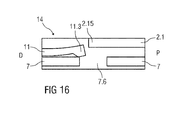
- a first shroud lock mechanism 14 is arranged to prevent retraction of the needle shroud 7 relative to the case 2 when the cap 11 is in place, thereby avoiding unintentional activation of the autoinjector 1 (e.g., if dropped, during shipping or packaging, etc.).
- the first shroud lock mechanism 14 may comprise one or more compliant beams 11.3 on the cap 11 and a respective number of apertures 7.6 in the needle shroud 7 adapted to receive each of the compliant beams 11.3.
- the compliant beams 11.3 abut a radial stop 2.15 on the case 2 which prevents the compliant beams 11.3 from disengaging the apertures 7.6.
- the compliant beams 11.3 may abut an edge of the aperture 7.6 and deflect to disengage the aperture 7.6, allowing for removal of the cap 11 and the protective needle sheath 5 attached thereto.
- the compliant beams 11.3 and/or the apertures 7.6 may be ramped to reduce force necessary to disengage the compliant beams 11.3 from the apertures 7.6.
- Figure 1B is a schematic side view of an exemplary embodiment of the autoinjector 1 according to the prevent invention during assembly.
- the case 2 is removed for clarity.
- Figure 1B and Figure 2 show a second shroud lock mechanism 15 that is adapted to lock the needle shroud 7 in an axial position relative to the case 2 after the autoinjector 1 has been removed from the injection site.
- the second shroud lock mechanism 15 comprises at least one compliant shroud beam 7.1 on the needle shroud 7 adapted to proximally abut a stop 2.12 on the case 2 after the autoinjector 1 has been removed from the injection site.
- the abutment of the shroud beam 7.1 on the stop 2.12 prevents translation of the needle shroud 7 in the proximal direction P relative to the case 2.
- the cap 11 Prior to use, when the cap 11 is attached to the autoinjector 1, the cap 11 is adapted to engage and deflect the compliant shroud beam 7.1 radially inward, allowing the shroud beam 7.1 to pass the stop 2.12 in the proximal direction P so that the needle shroud 7 can translate in the proximal direction P relative to the case 2.
- the autoinjector 1 may formed from at least two subassemblies, e.g., a control subassembly 1.1 and a drive subassembly 1.2, to allow for flexibility as to the time and location of manufacture of the subassemblies 1.1, 1.2 and final assembly with the syringe 3.
- FIG 3 is a perspective exploded view of an exemplary embodiment of a control subassembly 1.1 of an autoinjector 1 according to the present invention.
- the control subassembly 1.1 comprises the cap 11, the needle shroud 7, the shroud spring 8 and the front case 2.1.
- the shroud spring 8 is inserted into the needle shroud 7, and the needle shroud 7 with the shroud spring 8 is inserted into the front case 2.1.
- the cap 11 is arranged over the distal end of the needle shroud 7.
- FIG. 4 is a perspective exploded view of an exemplary embodiment of a drive subassembly 1.2 of an autoinjector 1 according to the present invention.
- the drive subassembly 1.2 the plunger 10, the drive spring 9 and the rear case 2.2.
- the drive spring 9 is inserted into the plunger 10 and the plunger 10 is inserted in the rear case 2.2 in the proximal direction P thereby compressing the drive spring 9.
- the plunger 10 and the drive spring 9 reach a compressed position it is rotated by an angle, e.g. approximately 30° relative to the rear case 2.2, to engage the plunger 10 to the rear case 2.2.
- the rear case 2.2 may have a cam surface to engage the plunger 10 to induce this rotation prior to the plunger 10 and the drive spring 9 reaching the compressed position.
- FIG. 5 is a perspective view of an exemplary embodiment of a needle sheath removal mechanism 13 of an autoinjector 1 according to the present invention.
- the needle sheath removal mechanism 13 comprises an opening 11.1 axially arranged in the cap 11.
- the opening 11.1 is approximately sized and shaped to receive the protective needle sheath 5.
- One or more bosses 11.2 may be disposed on a proximal end of the cap 11 and adapted to abut the protective needle sheath 5. For example, when the protective needle sheath 5 is inserted into the opening 11.1, the protective needle sheath 5 may deform around the bosses 11.2.
- the bosses 11.2 may be ramped to reduce force necessary to insert the protective needle sheath 5 into the opening 11.1.
- the bosses 11.2 may abut a proximal end of the protective needle sheath 5 to prevent translation of the protective needle sheath 5 in the proximal direction P relative to the cap 11.
- the bosses 11.2 on the cap 11 may abut the proximal end of the protective needle sheath 5 and push the protective needle sheath 5 in the distal direction D off of the needle 4. with their non-ramped distal face.
- Figure 6 is a schematic view of an exemplary embodiment of a plunger release mechanism 12 of the autoinjector 1 according to the present invention during assembly.
- the plunger release mechanism 12 is arranged for preventing release of the plunger 10 prior to retraction of the needle shroud 7 relative to the case 2 and for releasing the plunger 10 once the needle shroud 7 is sufficiently retracted.
- the plunger release mechanism 12 comprises the plunger 10, the rear case 2.2, and the needle shroud 7 interacting with each other.
- the needle shroud 7 is limited to axial movement relative to the case 2, and the plunger 10 can translate axially and rotate relative to the case 2.
- the plunger 10 comprises a first plunger boss 10.1 adapted to engage a shroud rib 7.7 on the needle shroud 7, a second plunger boss 10.2 adapted to engage a case slot 2.3 in the case 2, and a plunger rib 10.3 adapted to engage the shroud rib 7.7 on the needle shroud 7.
- the shroud rib 7.7 comprises a proximal face 7.8 adapted to engage the plunger rib 10.3, and a distal face 7.9 and a longitudinal face 7.10 adapted to engage the first plunger boss 10.1.
- a receiving element may be formed on the needle shroud 7 distal of the longitudinal face 7.10 of the shroud rib 7.7.
- the case slot 2.3 comprises a first angled surface 2.9 adapted to apply a rotational force in a first rotational direction R1 to the second plunger boss 10.2, a wall 2.10 adapted to abut the second plunger boss 10.2 to limit rotation of the plunger 10 relative to the case 2 in the first rotational direction R1, and a second angled surface 2.11 adapted to apply a rotational force in a second rotational direction R2, opposite the first rotational direction R1, to the second plunger boss 10.2.
- the plunger 10 with the drive spring 9 is inserted into the rear case 2.2.
- the plunger 10 is rotated in the first rotational direction R1 until the second plunger boss 10.2 is moved into the case slot 2.3 until it abuts the wall 2.10.
- the first angled surface 2.9 prevents the second plunger boss 10.2 from moving in the second rotational direction R2, and thus prevents the plunger 10 from rotating relative to the case 2.
- a pair of resilient beams 2.13 (shown in Figure 1 B) on the rear case 2.2 is adapted to snap into recesses 2.14 (shown in Figure 3 ) in the front case 2.1 to lock the drive subassembly 1.2 to the control subassembly 1.1.
- the needle shroud 7 translates proximally (e.g., by use of an assembly jig) causing the shroud rib 7.7 to abut the plunger rib 10.3.
- the angle of the plunger rib 10.3 causes the plunger 10 to rotate relative to the case 2 in the second rotational direction R2, and the second plunger boss 10.2 rides along the first angled surface 2.9 onto the second angled surface 2.11.
- the force of the drive spring 9 imparts a rotational force on the plunger 10 in the second rotational direction R2 due to the angle of the second angled surface 2.11.
- the needle shroud 7 when the needle shroud 7 is released (e.g., by removing the assembly jig), the needle shroud 7 translates in the distal direction D relative to the case 2 under the force the shroud spring 8 until the shroud rib 7.7 abuts the first plunger boss 10.1.
- the distal face 7.9 of the shroud rib 7.7 may abut the first plunger boss 10.1 and maintain the needle shroud 7 in an axial position relative to the case 2.
- the second plunger boss 10.2 is prevented from disengaging the case slot 2.3, because the shroud rib 7.7 prevents the plunger 10 from rotating in the second rotational direction R2 relative to the case 2.
- the longitudinal face 7.10 of the shroud rib 7.7 abuts the first plunger boss 10.1 to prevent rotation of the plunger 10.
- Figure 9 shows an exemplary embodiment of the first shroud lock mechanism 14 for an autoinjector 1 according to the present invention after assembly of the control subassembly 1.1.
- the compliant beam 11.3 on the cap is engaged in the aperture 7.6 within the needle shroud 7.
- the radial stop 2.15 is axially spaced from the compliant beam 11.3.
- Figure 10 shows an exemplary embodiment of the first shroud lock mechanism 14 for an autoinjector 1 according to the present invention during insertion of the syringe 3 into the control subassembly 1.1 for engaging the protective needle sheath 5 to the cap 11.
- the aperture 7.6 provides some clearance allowing a movement of the needle shroud 7 relative to the cap 11 in the distal direction D.
- the front case 2.1 is also moved in the distal direction D relative to the cap 11 axially aligning the radial stop 2.15 with the compliant beam 11.3 preventing the cap 11 from disengaging the needle shroud 7.
- Figure 11 shows an exemplary embodiment of the first shroud lock mechanism 14 for an autoinjector 1 according to the present invention, wherein after insertion of the syringe 3, the needle shroud 7 is moved further in the proximal direction P relative to the front case 2.1 by an assembly jig (not illustrated).
- the drive subassembly 1.2 may be assembled to the control subassembly 1.1.
- the compliant beam 11.3 remains engaged in the aperture 7.6 and the radial stop 2.15 prevents them from disengaging.
- the assembly jig is removed allowing the needle shroud 7 to move back in the distal direction D relative to the front case 2.1 under the force of the shroud spring 8 arriving again in the state illustrated in figure 10 .
- the needle shroud 7 is prevented from moving in the proximal direction P relative to the case 2, because the radial stop 2.15 prevents the compliant beam 11.3 from disengaging the aperture 7.6 and the rib 11.4 on the cap 11 proximally abuts the front case 2.1.
- Figure 12 shows an exemplary embodiment of the second shroud lock mechanism 15 for an autoinjector 1 according to the present invention after assembly of the control subassembly 1.1.
- the needle shroud 7 is partially inserted into the cap 11.
- the shroud beam 7.1 is in a non-deflected position proximally abutting the stop 2.12 in the front case 2.1. This prevents the needle shroud 7 from moving further in the proximal direction P relative to the front case 2.1 and keeps the control subassembly 1.1 locked together.
- Figure 13 shows an exemplary embodiment of the second shroud lock mechanism 15 for an autoinjector 1 according to the present invention during insertion of the syringe 3 into the control subassembly 1.1, wherein the needle shroud 7 is moved further in the distal direction D into the cap 11 such that the cap 11 radially inwardly deflects the shroud beam 7.1 out of its abutment with the stop 2.12.
- the needle shroud 7 is thus free to move in the proximal direction P relative to the front case 2.1.
- Figure 14 shows an exemplary embodiment of the second shroud lock mechanism 15 for an autoinjector 1 according to the present invention after final assembly of the drive subassembly 1.2 to the control subassembly 1.1.
- the needle shroud 7 has been moved further in the proximal direction P relative the front case 2.1 by an assembly jig (not illustrated).
- the drive subassembly 1.2 may be assembled to the control subassembly 1.1.
- the assembly jig is removed and the needle shroud 7 translates in the distal direction D relative to the front case 2.1 under the force of the shroud spring 8 until the shroud rib 7.7 abuts the first plunger boss 10.1.
- the shroud beam 7.1 is prevented from deflecting radially outward by the stop 2.12 in the front case 2.1.
- Figure 15A is a longitudinal section of an exemplary embodiment of an autoinjector 1 according to the present invention after final assembly
- Figure 15B is a schematic side view of an exemplary embodiment of an autoinjector 1 according to the present invention after final assembly, wherein the case 2 is removed for clarity.
- the autoinjector 1 may be kept in temperature controlled environment (e.g., cold chain storage) to, for example, reduce creep in highly stressed components, e.g. under load from the drive spring 9.
- temperature controlled environment e.g., cold chain storage
- the autoinjector 1 is removed from the packaging.
- the medicament in the syringe 3 may be visually inspected through a viewing window (not shown), which can be a transparent part of the case 2 or a cut-out in the case 2 aligned with the syringe 3.
- the cap 11 is removed by pulling it in the distal direction D away from the case 2.
- the bosses 11.2 on the cap 11 frictionally engage the protective needle sheath 5 and pull it off the needle 4 as the cap 11 is pulled in the distal direction D, and the compliant beam 11.3 disengages the aperture 7.6 in the needle shroud 7, as shown in Figure 16 .
- the compliant beam 11.3 translates distally within the aperture 7.6 until it is no longer abutted radially by the radial stop 2.15 and engages a proximal surface of the aperture 7.6 (which may be ramped) and deflects radially to disengage the aperture 7.6.
- the syringe 3 is fixed in position relative to the case 2, so pulling the cap 11 in the distal direction D does not cause any axial movement of the syringe 3.
- the syringe 3 is also fixedly rotationally relative to the case 2 (e.g., by an interference fit with the case 2 and/or the needle shroud 7).
- Figure 17A is a longitudinal section of an exemplary embodiment of the autoinjector 1 according to the present invention prior to use.
- Figure 17B is a schematic side view of an exemplary embodiment of the autoinjector 1 according to the present invention prior to use, wherein the case 2 is removed for clarity.
- the needle shroud 7 When the cap 11 is removed, the needle shroud 7 is in a first extended position FEP relative to the case 2, protruding from the case 2 in the distal direction D.
- the first extended position FEP is defined by the first plunger boss 10.1 abutting the shroud rib 7.7.
- Figure 18A is a longitudinal section of an exemplary embodiment of the autoinjector 1 according to the present invention during use.
- Figure 18B is a schematic side view of an exemplary embodiment of the autoinjector 1 according to the present invention during use, wherein the case 2 is removed for clarity.
- the needle shroud 7 may include an aperture, a recess or a slot proximal of the shroud rib 7.7 to accommodate the first plunger boss 10.1 when the needle shroud 7 is in the retracted position RP and the plunger 10 rotates relative to the case 2.
- the shroud rib 7.7 may include a resistance feature (e.g., a projection, a ramp, a recess, etc.) adapted to abut the first plunger boss 10.1 as the needle shroud 7 translates from the first extended position FEP to the retracted position RP.
- a resistance feature e.g., a projection, a ramp, a recess, etc.
- a tactile feedback is provided in the form of increased resistance to pressing the autoinjector 1 against the injection site. The tactile feedback may be used to indicate that needle 4 will be inserted into the injection site upon further depression of the autoinjector 1 against the injection site.
- the needle shroud and reposition as the needle shroud 7 will re-extend to its initial position under the force of the shroud spring 8.
- the needle shroud 7 is in the retracted position RP, the needle 4 has been inserted into the injection site.
- a penetration depth of the needle 4 may be varied by, for example, limiting retraction of the needle shroud 7 relative to the case 2, modifying an axial position of the syringe 3 relative to the case 2, modifying a length of the needle 4, etc.
- the autoinjector 1 of the present invention may be used for sub-cutaneous, intra-dermal and/or intra-muscular injection.
- Figure 20A is a longitudinal section of an exemplary embodiment of the autoinjector 1 according to the present invention during use.
- Figure 20B is a schematic side view of an exemplary embodiment of the autoinjector 1 according to the present invention during use, wherein the case 2 is removed for clarity.
- the plunger 10 When the plunger 10 has rotated a sufficient distance in the second rotational direction R2 such that the second plunger boss 10.2 disengages the case slot 2.3, the plunger 10 is free to translate axially, under the force of the drive spring 9, relative to the case 2 to push the stopper 6 to deliver the medicament M from the syringe 3 through the needle 4.
- disengagement of the first plunger boss 10.1 from the shroud rib 7.7 and/or the second plunger boss 10.2 from the case slot 2.3 may provide an audible feedback indicating that delivery of the medicament M has started.
- a viewing window in the case 2 may allow for a visual feedback that the plunger 10 is advancing within the syringe 3 for assessing the progress of displacement of the medicament M.
- Figure 21A is a longitudinal section of an exemplary embodiment of the autoinjector 1 according to the present invention after use.
- Figure 21B is a schematic side view of an exemplary embodiment of the autoinjector 1 according to the present invention after use, wherein the case 2 is removed for clarity.
- the needle shroud 7 When the autoinjector 1 is removed from the injection site, the needle shroud 7 translates distally relative to the case 2 from the retracted position RP to a second extended position SEP under the biasing force of the shroud spring 8.
- the needle shroud 7 In the second extended position SEP, the needle shroud 7 extends beyond a distal tip of the needle 4 and locks in an axial position relative to the case 2.
- the second extended position SEP prevents needle-stick injury and may also indicate that the autoinjector 1 has been used (because the needle shroud 7 cannot move proximally from the second extended position SEP).
- the needle shroud 7 protrudes further, e.g. 2 mm, from the case 2 than in the first extended position FEP.
- the needle shroud 7 may include an indicia (e.g., a red ring, text, a graphic) on a portion which is visually accessible when the needle shroud 7 is in the second extended position SEP but not in the first extended position FEP.
- the indicia may indicate that the autoinjector 1 has been used.
- FIG 22 is a schematic view of an exemplary embodiment of the second shroud lock mechanism 15 according to the present invention.
- the shroud beam 7.1 passes the stop 2.12 in the distal direction D and relaxes radially outwards which is possible as the cap 11 is no longer present.
- the needle shroud 7 cannot translate proximally relative to the case 2, because the shroud beam 7.1 abuts the stop 2.12. The needle shroud 7 is thus locked in the second extended position SEP.
- Extension of the needle shroud 7 distally beyond the second extended position SEP may be prevented by a shroud boss 7.2 on the needle shroud 7 that abuts a case boss 2.8 on the case 2 (see Figure 1 ).
- Figures 23A to 23E are schematic views of another exemplary embodiment of a plunger release mechanism 12 of the autoinjector 1 according to the present invention.
- the plunger release mechanism 12 is arranged for preventing release of the plunger 10 prior to retraction of the needle shroud 7 relative to the case 2 and for releasing the plunger 10 once the needle shroud 7 is sufficiently retracted.
- the plunger release mechanism 12 comprises the plunger 10, the rear case 2.2, and the needle shroud 7.
- the needle shroud 7 is limited to axial movement relative to the case 2, and the plunger 10 can translate axially and rotate relative to the case 2.
- the plunger 10 comprises a first plunger boss 10.1 adapted to engage a shroud rib 7.7 on the needle shroud 7, a second plunger boss 10.2 adapted to engage a case slot 2.3 in the case 2, and a plunger rib 10.3 adapted to engage the shroud rib 7.7 on the needle shroud 7.
- the shroud rib 7.7 is disposed in a plane substantially perpendicular to a longitudinal axis of the case 2.
- the shroud 7.7 comprises a proximal face 7.8 adapted to engage the plunger rib 10.3, and a distal face 7.9 adapted to engage the first plunger boss 10.1.
- the case slot 2.3 comprises a first angled surface 2.9 adapted to apply a rotational force in a first rotational direction R1 to the second plunger boss 10.2, a wall 2.10 adapted to abut the second plunger boss 10.2 to limit rotation of the plunger 10 relative to the case 2 in the first rotational direction R1, and a transversal surface 2.16 disposed in a plane substantially perpendicular to a longitudinal axis of the case 2.
- Figure 23A is a schematic view of an exemplary embodiment of the plunger release mechanism 12 of the autoinjector 1 according to the present invention during assembly of the drive subassembly 1.2.
- the plunger 10 with the drive spring 9 is inserted into the rear case 2.2.
- the plunger 10 is rotated in the first rotational direction R1 until the second plunger boss 10.2 is moved into the case slot 2.3 until it abuts the wall 2.10.
- the first angled surface 2.9 prevents the second plunger boss 10.2 from moving in the second rotational direction R2, and thus prevents the plunger 10 from rotating relative to the case 2.
- a pair of resilient beams 2.13 (shown in Figure 1 B) on the rear case 2.2 is adapted to snap into recesses 2.14 (shown in Figure 3 ) in the front case 2.1 to lock the drive subassembly 1.2 to the control subassembly 1.1.
- Figure 23B shows the drive assembly 1.2 being coupled to the control subassembly 1.1, wherein the needle shroud 7 translates proximally (e.g., by use of an assembly jig) causing the shroud rib 7.7 to abut the plunger rib 10.3.
- the angle of the plunger rib 10.3 causes the plunger 10 to rotate relative to the case 2 in the second rotational direction R2, and the second plunger boss 10.2 rides along the first angled surface 2.9 onto the transversal surface 2.16.
- the needle shroud 7 when the needle shroud 7 is released (e.g., by removing the assembly jig), the needle shroud 7 translates in the distal direction D relative to the case 2 under the force of the shroud spring 8 until the shroud rib 7.7 abuts the first plunger boss 10.1.
- the distal face 7.9 of the shroud rib 7.7 may abut the first plunger boss 10.1 and maintain the needle shroud 7 in an axial position relative to the case 2.
- the second plunger boss 10.2 is prevented from disengaging the case slot 2.3 as it abuts the transversal surface 2.16 in the distal direction D.
- Figure 23E shows an exemplary embodiment of the plunger release mechanism 12 when the needle shroud 7 is in the retracted position RP.
- the needle shroud 7 translates distally causing the shroud rib 7.7 to, starting from the position shown in figure 23D , ride along the plunger rib 10.3 thereby rotating the second plunger boss 10.2 in the second rotational direction R2 along the transversal surface 2.16 until the second plunger boss 10.2 disengages the case slot 2.3 thus releasing the plunger 10.
- the plunger 10 translates axially relative to the case 2 to deliver the medicament M from the syringe 3.
- a tactile feedback may be provided in the form of an increase in resistance when the needle shroud 7 abuts and pushes against the plunger rib 10.3.
- the tactile feedback may indicate that needle insertion will commence or medicament delivery will be initiated if the autoinjector 1 is pressed further against the injection site.
- transversal surface 2.16 could be replaced by or comprise a concave shape for preventing inadvertent release of the plunger 10.
- the plunger 10 may not have the first plunger boss 10.1, the plunger rib 10.3 may be disposed at different angle than as described above, and the case slot 2.3 may not be angled relative to a transverse axis of the case 2.
- the plunger 10 when the autoinjector 1 is assembled, the plunger 10 is maintained in axial position relative to the case 2, because the second plunger boss 10.2 engages the case slot 2.3.
- case slot 2.3 may not impart any rotational force on the second plunger boss 10.2 (or, in another exemplary embodiment, the case slot 2.3 may be angled to impart a rotational force on the second plunger boss 10.2 in the first rotational direction R1 to ensure that the second plunger boss 10.2 does not disengage the case slot 2.3 inadvertently).
- a tamper strip (not shown) may be arranged between the cap 11 and the front case 2.1 when the control subassembly 1.1 is assembled.
- the tamper strip may be useful for quality assurance.
- a force required to press the needle shroud 7 may be approximately 2-12 N.
- the syringe 3 used in the autoinjector 1 may be a syringe capable of containing approximately 1 mL of the medicament M. In another exemplary embodiment, the syringe 3 used in the autoinjector 1 may be a syringe capable of containing approximately 2mL of the medicament M.
- the autoinjector 1 according to the present invention may have an increased shelf-life compared to conventional autoinjectors, because, for example, only the plunger 10 is subjected to the relatively high force of the drive spring 9.
- the autoinjector 1 according to the present invention may be used as a platform as the drive spring 9 can be changed to alter a force applied to the plunger 10, e.g., for delivering medicaments with different viscosities drugs or reconstituted medicaments, or changing a time required to inject a dose of the medicament.
- drug or “medicament”, as used herein, means a pharmaceutical formulation containing at least one pharmaceutically active compound, wherein in one embodiment the pharmaceutically active compound has a molecular weight up to 1500 Da and/or is a peptide, a proteine, a polysaccharide, a vaccine, a DNA, a RNA, an enzyme, an antibody or a fragment thereof, a hormone or an oligonucleotide, or a mixture of the above-mentioned pharmaceutically active compound, wherein in a further embodiment the pharmaceutically active compound is useful for the treatment and/or prophylaxis of diabetes mellitus or complications associated with diabetes mellitus such as diabetic retinopathy, thromboembolism disorders such as deep vein or pulmonary thromboembolism, acute coronary syndrome (ACS), angina, myocardial infarction, cancer, macular degeneration, inflammation, hay fever, atherosclerosis and/or rheumatoid arthritis, wherein in a further
- Insulin analogues are for example Gly(A21), Arg(B31), Arg(B32) human insulin; Lys(B3), Glu(B29) human insulin; Lys(B28), Pro(B29) human insulin; Asp(B28) human insulin; human insulin, wherein proline in position B28 is replaced by Asp, Lys, Leu, Val or Ala and wherein in position B29 Lys may be replaced by Pro; Ala(B26) human insulin; Des(B28-B30) human insulin; Des(B27) human insulin and Des(B30) human insulin.
- Insulin derivates are for example B29-N-myristoyl-des(B30) human insulin; B29-N-palmitoyl-des(B30) human insulin; B29-N-myristoyl human insulin; B29-N-palmitoyl human insulin; B28-N-myristoyl LysB28ProB29 human insulin; B28-N-palmitoyl-LysB28ProB29 human insulin; B30-N-myristoyl-ThrB29LysB30 human insulin; B30-N-palmitoyl- ThrB29LysB30 human insulin; B29-N-(N-palmitoyl-Y-glutamyl)-des(B30) human insulin; B29-N-(N-lithocholyl-Y-glutamyl)-des(B30) human insulin; B29-N-( ⁇ -carboxyheptadecanoyl)-des(B30) human insulin and B29-N-( ⁇ -carbox
- Exendin-4 for example means Exendin-4(1-39), a peptide of the sequence H-His-Gly-Glu-Gly-Thr-Phe-Thr-Ser-Asp-Leu-Ser-Lys-Gln-Met-Glu-Glu-Glu-Ala-Val-Arg-Leu-Phe-Ile-Glu-Trp-Leu-Lys-Asn-Gly-Gly-Pro-Ser-Ser-Gly-Ala-Pro-Pro-Pro-Ser-NH2.
- Exendin-4 derivatives are for example selected from the following list of compounds:
- Hormones are for example hypophysis hormones or hypothalamus hormones or regulatory active peptides and their antagonists as listed in Rote Liste, ed. 2008, Chapter 50 , such as Gonadotropine (Follitropin, Lutropin, Choriongonadotropin, Menotropin), Somatropine (Somatropin), Desmopressin, Terlipressin, Gonadorelin, Triptorelin, Leuprorelin, Buserelin, Nafarelin, Goserelin.
- Gonadotropine Follitropin, Lutropin, Choriongonadotropin, Menotropin
- Somatropine Somatropin
- Desmopressin Terlipressin
- Gonadorelin Triptorelin
- Leuprorelin Buserelin
- Nafarelin Goserelin.
- a polysaccharide is for example a glucosaminoglycane, a hyaluronic acid, a heparin, a low molecular weight heparin or an ultra low molecular weight heparin or a derivative thereof, or a sulphated, e.g. a poly-sulphated form of the above-mentioned polysaccharides, and/or a pharmaceutically acceptable salt thereof.
- An example of a pharmaceutically acceptable salt of a poly-sulphated low molecular weight heparin is enoxaparin sodium.
- Antibodies are globular plasma proteins ( ⁇ 150 kDa) that are also known as immunoglobulins which share a basic structure. As they have sugar chains added to amino acid residues, they are glycoproteins.
- the basic functional unit of each antibody is an immunoglobulin (Ig) monomer (containing only one lg unit); secreted antibodies can also be dimeric with two lg units as with IgA, tetrameric with four lg units like teleost fish IgM, or pentameric with five lg units, like mammalian IgM.
- Ig immunoglobulin
- the lg monomer is a "Y"-shaped molecule that consists of four polypeptide chains; two identical heavy chains and two identical light chains connected by disulfide bonds between cysteine residues. Each heavy chain is about 440 amino acids long; each light chain is about 220 amino acids long. Heavy and light chains each contain intrachain disulfide bonds which stabilize their folding. Each chain is composed of structural domains called lg domains. These domains contain about 70-110 amino acids and are classified into different categories (for example, variable or V, and constant or C) according to their size and function. They have a characteristic immunoglobulin fold in which two ⁇ sheets create a "sandwich" shape, held together by interactions between conserved cysteines and other charged amino acids.
- lg heavy chain There are five types of mammalian lg heavy chain denoted by ⁇ , ⁇ , ⁇ , ⁇ , and p.
- the type of heavy chain present defines the isotype of antibody; these chains are found in IgA, IgD, IgE, IgG, and IgM antibodies, respectively.
- Distinct heavy chains differ in size and composition; ⁇ and ⁇ contain approximately 450 amino acids and ⁇ approximately 500 amino acids, while ⁇ and ⁇ have approximately 550 amino acids.
- Each heavy chain has two regions, the constant region (C H ) and the variable region (V H ).
- the constant region is essentially identical in all antibodies of the same isotype, but differs in antibodies of different isotypes.
- Heavy chains ⁇ , ⁇ and ⁇ have a constant region composed of three tandem lg domains, and a hinge region for added flexibility; heavy chains ⁇ and ⁇ have a constant region composed of four immunoglobulin domains.
- variable region of the heavy chain differs in antibodies produced by different B cells, but is the same for all antibodies produced by a single B cell or B cell clone.
- the variable region of each heavy chain is approximately 110 amino acids long and is composed of a single lg domain.
- a light chain has two successive domains: one constant domain (CL) and one variable domain (VL).
- CL constant domain
- VL variable domain
- the approximate length of a light chain is 211 to 217 amino acids.
- Each antibody contains two light chains that are always identical; only one type of light chain, ⁇ or ⁇ , is present per antibody in mammals.
- variable (V) regions are responsible for binding to the antigen, i.e. for its antigen specificity.
- VL variable light
- VH variable heavy chain
- CDRs Complementarity Determining Regions
- an "antibody fragment” contains at least one antigen binding fragment as defined above, and exhibits essentially the same function and specificity as the complete antibody of which the fragment is derived from.
- Limited proteolytic digestion with papain cleaves the lg prototype into three fragments. Two identical amino terminal fragments, each containing one entire L chain and about half an H chain, are the antigen binding fragments (Fab).
- the Fc contains carbohydrates, complement-binding, and FcR-binding sites.
- F(ab')2 is divalent for antigen binding.
- the disulfide bond of F(ab')2 may be cleaved in order to obtain Fab'.
- the variable regions of the heavy and light chains can be fused together to form a single chain variable fragment (scFv).
- Pharmaceutically acceptable salts are for example acid addition salts and basic salts.
- Acid addition salts are e.g. HCl or HBr salts.
- Basic salts are e.g. salts having a cation selected from alkali or alkaline, e.g. Na+, or K+, or Ca2+, or an ammonium ion N+(R1)(R2)(R3)(R4), wherein R1 to R4 independently of each other mean: hydrogen, an optionally substituted C1-C6-alkyl group, an optionally substituted C2-C6-alkenyl group, an optionally substituted C6-C10-aryl group, or an optionally substituted C6-C10-heteroaryl group.
- solvates are for example hydrates.
Priority Applications (25)
| Application Number | Priority Date | Filing Date | Title |
|---|---|---|---|
| EP13175664.5A EP2823841A1 (en) | 2013-07-09 | 2013-07-09 | Autoinjector |
| NO14745095A NO3019220T3 (no) | 2013-07-09 | 2014-07-07 | |
| DK14745095.1T DK3019220T3 (en) | 2013-07-09 | 2014-07-07 | autoinjector |
| RU2016103901A RU2678374C2 (ru) | 2013-07-09 | 2014-07-07 | Автоматическое инъекционное устройство |
| TR2018/02806T TR201802806T4 (tr) | 2013-07-09 | 2014-07-07 | Oto enjektör. |
| EP17197256.5A EP3305348A3 (en) | 2013-07-09 | 2014-07-07 | Autoinjector |
| ES14745095.1T ES2660297T3 (es) | 2013-07-09 | 2014-07-07 | Autoinyector |
| AU2014289352A AU2014289352B2 (en) | 2013-07-09 | 2014-07-07 | Autoinjector |
| CN201911066019.5A CN111001060B (zh) | 2013-07-09 | 2014-07-07 | 自动注射器 |
| PL14745095T PL3019220T3 (pl) | 2013-07-09 | 2014-07-07 | Automatyczny wstrzykiwacz |
| ARP140102515A AR096836A1 (es) | 2013-07-09 | 2014-07-07 | Auto-inyector |
| HUE14745095A HUE035943T2 (hu) | 2013-07-09 | 2014-07-07 | Automata fecskendõ |
| CN201480048985.3A CN105517599B (zh) | 2013-07-09 | 2014-07-07 | 自动注射器 |
| EP14745095.1A EP3019220B1 (en) | 2013-07-09 | 2014-07-07 | Autoinjector |
| PCT/EP2014/064427 WO2015004052A1 (en) | 2013-07-09 | 2014-07-07 | Autoinjector |
| KR1020167002897A KR102265926B1 (ko) | 2013-07-09 | 2014-07-07 | 자동 주사기 |
| US14/903,359 US10398848B2 (en) | 2013-07-09 | 2014-07-07 | Autoinjector |
| MX2016000310A MX368904B (es) | 2013-07-09 | 2014-07-07 | Auto-inyector. |
| TW103123257A TW201513909A (zh) | 2013-07-09 | 2014-07-07 | 自動注射器(六) |
| JP2016524776A JP6498189B2 (ja) | 2013-07-09 | 2014-07-07 | 自己注射器(Autoinjector) |
| IL243225A IL243225B (en) | 2013-07-09 | 2015-12-24 | Self-injecting syringe |
| HK16109072.4A HK1220929A1 (zh) | 2013-07-09 | 2016-07-29 | 自動注射器 |
| AU2018271229A AU2018271229B2 (en) | 2013-07-09 | 2018-11-26 | Autoinjector |
| US16/521,266 US11541188B2 (en) | 2013-07-09 | 2019-07-24 | Autoinjector |
| US18/082,253 US20230126164A1 (en) | 2013-07-09 | 2022-12-15 | Autoinjector |
Applications Claiming Priority (1)
| Application Number | Priority Date | Filing Date | Title |
|---|---|---|---|
| EP13175664.5A EP2823841A1 (en) | 2013-07-09 | 2013-07-09 | Autoinjector |
Publications (1)
| Publication Number | Publication Date |
|---|---|
| EP2823841A1 true EP2823841A1 (en) | 2015-01-14 |
Family
ID=48747446
Family Applications (3)
| Application Number | Title | Priority Date | Filing Date |
|---|---|---|---|
| EP13175664.5A Withdrawn EP2823841A1 (en) | 2013-07-09 | 2013-07-09 | Autoinjector |
| EP14745095.1A Active EP3019220B1 (en) | 2013-07-09 | 2014-07-07 | Autoinjector |
| EP17197256.5A Pending EP3305348A3 (en) | 2013-07-09 | 2014-07-07 | Autoinjector |
Family Applications After (2)
| Application Number | Title | Priority Date | Filing Date |
|---|---|---|---|
| EP14745095.1A Active EP3019220B1 (en) | 2013-07-09 | 2014-07-07 | Autoinjector |
| EP17197256.5A Pending EP3305348A3 (en) | 2013-07-09 | 2014-07-07 | Autoinjector |
Country Status (19)
| Country | Link |
|---|---|
| US (3) | US10398848B2 (no) |
| EP (3) | EP2823841A1 (no) |
| JP (1) | JP6498189B2 (no) |
| KR (1) | KR102265926B1 (no) |
| CN (2) | CN105517599B (no) |
| AR (1) | AR096836A1 (no) |
| AU (2) | AU2014289352B2 (no) |
| DK (1) | DK3019220T3 (no) |
| ES (1) | ES2660297T3 (no) |
| HK (1) | HK1220929A1 (no) |
| HU (1) | HUE035943T2 (no) |
| IL (1) | IL243225B (no) |
| MX (1) | MX368904B (no) |
| NO (1) | NO3019220T3 (no) |
| PL (1) | PL3019220T3 (no) |
| RU (1) | RU2678374C2 (no) |
| TR (1) | TR201802806T4 (no) |
| TW (1) | TW201513909A (no) |
| WO (1) | WO2015004052A1 (no) |
Cited By (10)
| Publication number | Priority date | Publication date | Assignee | Title |
|---|---|---|---|---|
| WO2016193352A1 (en) * | 2015-06-03 | 2016-12-08 | Sanofi-Aventis Deutschland Gmbh | Shroud lock |
| WO2016193350A1 (en) * | 2015-06-03 | 2016-12-08 | Sanofi-Aventis Deutschland Gmbh | Drug delivery device |
| EP3117855A1 (en) * | 2015-07-15 | 2017-01-18 | Sanofi-Aventis Deutschland GmbH | Cap and cap removal device |
| EP3207952A1 (en) * | 2016-02-16 | 2017-08-23 | Carebay Europe Ltd. | An automatic feedback mechanism and a medicament delivery device with user feedback capability |
| WO2018041798A1 (en) | 2016-08-30 | 2018-03-08 | Sanofi-Aventis Deutschland Gmbh | Supplementary device for an injection device |
| WO2018166985A1 (en) | 2017-03-13 | 2018-09-20 | Sanofi-Aventis Deutschland Gmbh | Drug delivery device |
| WO2019086564A1 (en) * | 2017-11-03 | 2019-05-09 | Sanofi | Drug delivery device |
| RU2720168C2 (ru) * | 2015-06-03 | 2020-04-24 | Санофи-Авентис Дойчланд Гмбх | Держатель шприца и автоматическое инъекционное устройство |
| WO2020173995A1 (en) | 2019-02-26 | 2020-09-03 | Becton Dickinson France | Auto-injector with cap |
| EP4292626A3 (en) * | 2015-06-03 | 2024-03-13 | Sanofi-Aventis Deutschland GmbH | Audible indicator for a drug delivery device |
Families Citing this family (34)
| Publication number | Priority date | Publication date | Assignee | Title |
|---|---|---|---|---|
| EP2399635A1 (en) | 2010-06-28 | 2011-12-28 | Sanofi-Aventis Deutschland GmbH | Auto-injector |
| EP2823841A1 (en) | 2013-07-09 | 2015-01-14 | Sanofi-Aventis Deutschland GmbH | Autoinjector |
| EP2923714A1 (en) | 2014-03-28 | 2015-09-30 | Sanofi-Aventis Deutschland GmbH | Autoinjector triggered by skin contact |
| GB2537638A (en) * | 2015-04-21 | 2016-10-26 | Consort Medical Plc | Medicament delivery device |
| TW201707741A (zh) * | 2015-06-03 | 2017-03-01 | 賽諾菲阿凡提斯德意志有限公司 | 針頭護罩之抓握器、蓋子、自動注射器及製造抓握器之方法 |
| US20230166046A1 (en) * | 2016-02-29 | 2023-06-01 | Shl Medical Ag | Delivery device |
| CH712753A2 (de) | 2016-07-28 | 2018-01-31 | Tecpharma Licensing Ag | Trennen einer Nadelschutzkappe von einem Produktbehälter und Verfahren zum Montieren einer Injektionsvorrichtung. |
| DK3576809T3 (da) * | 2017-02-06 | 2023-07-31 | Sanofi Aventis Deutschland | Samlerede til en pentype injektionsanordning med låsefunktion |
| EP3406283A1 (en) * | 2017-05-26 | 2018-11-28 | Becton, Dickinson and Company | Pen needle |
| WO2019101689A1 (en) | 2017-11-21 | 2019-05-31 | Sanofi | Drive subassembly for a drug delivery device |
| EP3492126A1 (en) | 2017-12-01 | 2019-06-05 | Sanofi | Injector device |
| GB2570319B (en) | 2018-01-19 | 2021-01-06 | Consort Medical Plc | A medicament delivery device |
| JP7184910B2 (ja) * | 2018-02-16 | 2022-12-06 | ベクトン ディキンソン フランス | 医薬品組成物で充填された医療用容器を支持するための医療用注射デバイス |
| JP7194756B2 (ja) | 2018-06-08 | 2022-12-22 | アンタレス・ファーマ・インコーポレーテッド | 自動挿入注射器 |
| USD921897S1 (en) * | 2019-07-02 | 2021-06-08 | Tom Chi | Acupuncture needle |
| CA3167233A1 (en) * | 2020-02-14 | 2021-08-19 | Taisei Kako Co., Ltd. | Injection device |
| EP4112099A1 (en) | 2021-07-01 | 2023-01-04 | Phillips-Medisize A/S | Smart auto injector and cassette system |
| EP4112098A1 (en) | 2021-07-01 | 2023-01-04 | Phillips-Medisize A/S | Auto injector and cassette system with a cap removal mechanism |
| EP4112101A1 (en) | 2021-07-01 | 2023-01-04 | Phillips-Medisize A/S | Auto injector with release clutch function |
| EP4112100A1 (en) * | 2021-07-01 | 2023-01-04 | Phillips-Medisize A/S | Cassette with syringe holder lid |
| EP4112097A1 (en) | 2021-07-01 | 2023-01-04 | Phillips-Medisize A/S | Auto injector and cassette system with index ring in the cassette |
| CA3235380A1 (en) | 2021-10-20 | 2023-04-27 | Elizabeth Laws | Methods for treating prurigo nodularis by administering an il-4r antagonist |
| WO2023110904A1 (en) | 2021-12-15 | 2023-06-22 | Sanofi | Assembly for an injection device and an injection device |
| WO2023110884A1 (en) | 2021-12-15 | 2023-06-22 | Sanofi | Drug delivery arrangement comprising a skin pinching mechanism |
| WO2023110879A1 (en) | 2021-12-15 | 2023-06-22 | Sanofi | Drug delivery device with improved needle cover |
| WO2023110877A1 (en) | 2021-12-15 | 2023-06-22 | Sanofi | Drug delivery arrangement |
| WO2023110881A1 (en) | 2021-12-15 | 2023-06-22 | Sanofi | Drug delivery arrangement comprising a tissue receiving element |
| WO2023110883A1 (en) | 2021-12-15 | 2023-06-22 | Sanofi | Drug delivery device with adjustable injection depth |
| WO2023110893A1 (en) | 2021-12-15 | 2023-06-22 | Sanofi | Assembly for an injection device, injection device comprising such an assembly, medicament container for such an assembly, and method for producing such a medicament container |
| US20230220089A1 (en) | 2021-12-30 | 2023-07-13 | Regeneron Pharmaceuticals, Inc. | Methods for attenuating atopic march by administering an il-4/il-13 antagonist |
| WO2023215267A1 (en) | 2022-05-02 | 2023-11-09 | Regeneron Pharmaceuticals, Inc. | Anti-interleukin-4 receptor (il-4r) antibody formulations |
| WO2023245048A1 (en) | 2022-06-15 | 2023-12-21 | Bioverativ Usa Inc. | Anti-complement c1s antibody formulation |
| WO2023250507A1 (en) | 2022-06-24 | 2023-12-28 | Bioverativ Usa Inc. | Methods for treating complement-mediated diseases |
| WO2024011251A1 (en) | 2022-07-08 | 2024-01-11 | Regeneron Pharmaceuticals, Inc. | Methods for treating eosinophilic esophagitis in pediatric by administering an il-4r antagonist |
Citations (5)
| Publication number | Priority date | Publication date | Assignee | Title |
|---|---|---|---|---|
| WO2005097238A2 (en) * | 2004-03-30 | 2005-10-20 | Pediamed Pharmaceuticals, Inc. | Automatic injection device |
| EP2399634A1 (en) * | 2010-06-28 | 2011-12-28 | Sanofi-Aventis Deutschland GmbH | Needle safety arrangement and method for operating it |
| EP2468334A1 (en) * | 2010-12-21 | 2012-06-27 | Sanofi-Aventis Deutschland GmbH | Auto-injector |
| EP2606924A1 (en) * | 2011-12-21 | 2013-06-26 | Sanofi-Aventis Deutschland GmbH | Autoinjector having a retracting syringe carrier |
| EP2606925A1 (en) * | 2011-12-21 | 2013-06-26 | Sanofi-Aventis Deutschland GmbH | Autoinjector |
Family Cites Families (176)
| Publication number | Priority date | Publication date | Assignee | Title |
|---|---|---|---|---|
| GB9200219D0 (en) | 1992-01-07 | 1992-02-26 | Medimech Int Ltd | Automatic injectors |
| WO1994011041A1 (en) | 1992-11-19 | 1994-05-26 | R G S.A.S. Di Rosaria Galli & C. | Disposable auto-injector for prefilled syringes |
| US5658259A (en) | 1995-10-19 | 1997-08-19 | Meridian Medical Technologies, Inc. | Dental cartridge assembly auto-injector with protective needle cover |
| US5709662A (en) * | 1996-08-23 | 1998-01-20 | Becton Dickinson France, S.A. | Cartridge for an injection device |
| US5693023A (en) | 1996-11-15 | 1997-12-02 | Adventec, Inc. | Syringe with retractable needle assembly |
| IE970782A1 (en) | 1997-10-22 | 1999-05-05 | Elan Corp | An improved automatic syringe |
| DE29801168U1 (de) | 1998-01-24 | 1999-08-12 | Medico Dev Investment Co | Injektionsgerät |
| HU222513B1 (hu) | 1998-01-30 | 2003-08-28 | Novo Nordisk A/S | Injekciós fecskendő |
| DE19822031C2 (de) | 1998-05-15 | 2000-03-23 | Disetronic Licensing Ag | Autoinjektionsgerät |
| US6277099B1 (en) | 1999-08-06 | 2001-08-21 | Becton, Dickinson And Company | Medication delivery pen |
| US6673035B1 (en) | 1999-10-22 | 2004-01-06 | Antares Pharma, Inc. | Medical injector and medicament loading system for use therewith |
| US6663602B2 (en) | 2000-06-16 | 2003-12-16 | Novo Nordisk A/S | Injection device |
| PT2258424E (pt) | 2001-05-16 | 2013-03-28 | Lilly Co Eli | Aparelho injector de medicamento |
| DE10237258B4 (de) | 2002-08-14 | 2006-09-21 | Tecpharma Licensing Ag | Injektionsvorrichtung |
| GB0229345D0 (en) | 2002-12-17 | 2003-01-22 | Safe T Ltd | Hollow needle applicators |
| US7252651B2 (en) | 2003-01-07 | 2007-08-07 | Becton, Dickinson And Company | Disposable injection device |
| GB0304822D0 (en) | 2003-03-03 | 2003-04-09 | Dca Internat Ltd | Improvements in and relating to a pen-type injector |
| US7500963B2 (en) | 2003-07-22 | 2009-03-10 | Safety Syringes, Inc. | Systems and methods for automatic medical injection with safeguard |
| US20050027255A1 (en) | 2003-07-31 | 2005-02-03 | Sid Technologies, Llc | Automatic injector |
| CA2530263C (en) | 2003-08-12 | 2012-04-17 | Eli Lilly And Company | Medication dispensing apparatus with triple screw threads for mechanical advantage |
| US7635348B2 (en) | 2003-11-04 | 2009-12-22 | Meridian Medical Technologies, Inc. | Container for medicament automatic injector and automatic injector adapted therefor |
| EP1541185A1 (en) | 2003-12-08 | 2005-06-15 | Novo Nordisk A/S | Automatic syringe with priming mechanism |
| GB2410188B (en) | 2004-01-23 | 2006-01-25 | Medical House Plc | Injection device |
| US8048035B2 (en) * | 2004-08-06 | 2011-11-01 | Meridian Medical Technologies, Inc. | Automatic injector with needle cover |
| PL1819382T3 (pl) | 2004-10-21 | 2010-03-31 | Novo Nordisk As | Urządzenie wstrzykujące ze sprężyną skrętną i obrotowym wskaźnikiem |
| JP4990151B2 (ja) | 2004-10-21 | 2012-08-01 | ノボ・ノルデイスク・エー/エス | 内部投与量表示器を備えた注射器 |
| EP1814615B1 (en) | 2004-11-24 | 2015-10-28 | SHL Group AB | Injection device |
| DE102004063648A1 (de) | 2004-12-31 | 2006-07-20 | Tecpharma Licensing Ag | Injektions- oder Infusionsgerät mit Lebensdauer-Ermittlungseinrichtung |
| JP4903160B2 (ja) | 2005-01-18 | 2012-03-28 | ウォックハート アメリカズ インコーポレイテッド | ペン型薬物注入デバイス |
| CA2594764C (en) | 2005-01-21 | 2014-01-14 | Novo Nordisk A/S | An automatic injection device with a top release mechanism |
| JP5216328B2 (ja) | 2005-01-24 | 2013-06-19 | アンタレス ファーマ インコーポレイテッド | あらかじめ充填された針補助シリンジジェット式注射器 |
| US9011386B2 (en) | 2005-06-01 | 2015-04-21 | Shl Group Ab | Device for delivering medicament |
| DE602005008404D1 (de) | 2005-06-01 | 2008-09-04 | Shl Medical Ab | Medikamentenabgabevorrichtung |
| ATE519513T1 (de) | 2005-07-08 | 2011-08-15 | Novo Nordisk As | Injektionsvorrichtung |
| GB2433032A (en) | 2005-12-08 | 2007-06-13 | Owen Mumford Ltd | Syringe with dose adjustment means |
| US20070173770A1 (en) * | 2006-01-23 | 2007-07-26 | The Medical House Plc | Injection device |
| US20090005735A1 (en) | 2006-03-03 | 2009-01-01 | Shl Group Ab | Medical Device with Orientation Sensitive Priming Mechanism |
| FR2899482A1 (fr) | 2006-04-11 | 2007-10-12 | Becton Dickinson France Soc Pa | Dispositif d'injection automatique |
| US8251947B2 (en) | 2006-05-03 | 2012-08-28 | Antares Pharma, Inc. | Two-stage reconstituting injector |
| WO2007131025A1 (en) | 2006-05-03 | 2007-11-15 | Antares Pharma, Inc. | Injector with adjustable dosing |
| DE102006038103B4 (de) | 2006-08-14 | 2017-02-23 | Tecpharma Licensing Ag | Injektionsvorrichtung mit variabler Gewindeführung |
| EP2077878B1 (de) | 2006-09-15 | 2020-01-01 | TecPharma Licensing AG | Injektionsgerät mit verbessertem förderelement |
| ATE514443T1 (de) | 2006-12-13 | 2011-07-15 | Shl Group Ab | Autoinjektor |
| GB0704351D0 (en) * | 2007-03-07 | 2007-04-11 | Medical House Plc The | Improved autoinjector |
| US20080228147A1 (en) | 2007-03-15 | 2008-09-18 | Bristol-Myers Squibb Company | Injector for use with pre-filled syringes and method of assembly |
| CN101678168B (zh) * | 2007-03-22 | 2013-03-06 | 特克法马许可公司 | 具有受控制的注射针拉回功能的注射装置 |
| CN101674857A (zh) | 2007-03-22 | 2010-03-17 | 特克法马许可公司 | 具有触发保险的注射装置 |
| JP5128658B2 (ja) | 2007-04-05 | 2013-01-23 | テクファーマ・ライセンシング・アクチェンゲゼルシャフト | 機能的な駆動素子を備える投与装置 |
| DE102007016811A1 (de) | 2007-04-05 | 2008-10-09 | Tecpharma Licensing Ag | Vorrichtung zur Verabreichung eines fluiden Wirkstoffes aus einer Mehrkammerampulle |
| US8376997B2 (en) | 2007-06-19 | 2013-02-19 | Shl Group Ab | Device for delivering medicament |
| US9242044B2 (en) | 2007-07-06 | 2016-01-26 | Novo Nordisk A/S | Automatic injection device |
| AU2008300703B2 (en) | 2007-09-18 | 2011-03-17 | Shl Group Ab | Automatic injection device with needle insertion |
| EP2211947B1 (en) * | 2007-09-25 | 2018-11-07 | Becton Dickinson France | Autoinjector with deactivating means moveable by a safety shield |
| WO2009040603A1 (en) | 2007-09-25 | 2009-04-02 | Becton Dickinson France | Autoinjector with deshielder comprising tamper evidence means |
| EP2219710B2 (en) | 2007-11-12 | 2020-08-05 | Medicom Innovation Partner a/s | Auto injector with automatic needle retraction |
| US8771237B2 (en) | 2007-12-20 | 2014-07-08 | Novo Nordisk A/S | Injection device for delivering a fixed dose of liquid drug |
| US8992484B2 (en) | 2008-01-23 | 2015-03-31 | Novo Nordisk A/S | Device for injecting apportioned doses of liquid drug |
| PL2254624T3 (pl) | 2008-02-12 | 2015-01-30 | Shl Group Ab | Automatyczne urządzenie wstrzykujące |
| US8178748B2 (en) | 2008-02-15 | 2012-05-15 | The Procter & Gamble Company | Absorbent article |
| DE102008011885A1 (de) | 2008-02-29 | 2009-09-10 | Tecpharma Licensing Ag | Doppelfunktionsfeder |
| WO2009114542A1 (en) | 2008-03-10 | 2009-09-17 | Antares Pharma, Inc. | Injector safety device |
| GB2460398A (en) | 2008-05-20 | 2009-12-02 | Owen Mumford Ltd | Auto-injector having a magnetic injection indicator and a needle sheath retainer |
| AU2009279719B2 (en) | 2008-08-05 | 2015-07-23 | Antares Pharma, Inc. | Multiple dosage injector |
| DE102008037310B4 (de) | 2008-08-11 | 2023-11-16 | Ypsomed Ag | Automatische Injektionsvorrichtung für die Verabreichung einer festen Dosis |
| WO2010033790A2 (en) | 2008-09-18 | 2010-03-25 | Becton, Dickinson And Company | Medical injector with rotatable body portions |
| EP2328639B1 (en) * | 2008-09-18 | 2017-02-15 | Becton, Dickinson and Company | Medical injector with dose knob activation for automated reconstitution |
| CN102209563B (zh) | 2008-09-29 | 2014-04-23 | 贝克顿迪金森法国公司 | 带有完成注射声响指示的自动注射装置 |
| WO2010035057A1 (en) | 2008-09-29 | 2010-04-01 | Becton Dickinson France | Autoinjector with audible indication of completed delivery |
| ES2447845T3 (es) | 2008-10-01 | 2014-03-13 | Shl Group Ab | Dispositivo de administración de medicamento impulsado por resorte espiral cónico |
| DK2355867T3 (da) * | 2008-12-12 | 2014-09-08 | Shl Group Ab | Anordning til medikamentafgivelse |
| MY159791A (en) | 2008-12-12 | 2017-01-31 | Sanofi Aventis Deutschland | Resettable drive mechanism for a medication delivery device and medication delivery device |
| US8840591B2 (en) | 2008-12-12 | 2014-09-23 | Sanofi-Aventis Deutschland Gmbh | Drive mechanism for a medication delivery device and medication delivery device |
| US8968258B2 (en) | 2008-12-12 | 2015-03-03 | Sanofi-Aventis Deutschland Gmbh | Resettable drive mechanism for a medication delivery device and medication delivery device |
| EP2196233A1 (en) | 2008-12-12 | 2010-06-16 | Sanofi-Aventis Deutschland GmbH | Resettable drive mechanism for a medication delivery device and medication delivery device |
| US9089652B2 (en) | 2008-12-12 | 2015-07-28 | Sanofi-Aventis Deutschland Gmbh | Drive mechanism for a medication delivery device and medication delivery device |
| GB0900930D0 (en) | 2009-01-20 | 2009-03-04 | Future Injection Technologies Ltd | Injection device |
| EP2208503A1 (en) | 2009-01-20 | 2010-07-21 | Sanofi-Aventis Deutschland GmbH | Drive assembly and medication delivery device |
| AR075234A1 (es) | 2009-02-05 | 2011-03-16 | Sanofi Aventis Deutschland | Dispositivos de administracion de medicamentos. |
| MY154425A (en) | 2009-02-05 | 2015-06-15 | Sanofi Aventis Deutschland | Medicament delivery devices |
| KR101366427B1 (ko) | 2009-03-13 | 2014-02-24 | 일라이 릴리 앤드 캄파니 | 주사 후 시린지가 자동 후퇴되는 약물 주사 장치 |
| AU2010226442A1 (en) | 2009-03-20 | 2011-10-13 | Antares Pharma, Inc. | Hazardous agent injection system |
| JP5667160B2 (ja) | 2009-03-31 | 2015-02-12 | サノフィ−アベンティス・ドイチュラント・ゲゼルシャフト・ミット・ベシュレンクテル・ハフツング | 薬剤送達デバイスにおける及び薬剤送達デバイスに関する改良 |
| JP5677411B2 (ja) | 2009-04-29 | 2015-02-25 | アッヴィ バイオテクノロジー リミテッド | 自動注入機器 |
| EP2435112B1 (de) | 2009-05-29 | 2015-05-13 | Tecpharma Licensing AG | Injektionsvorrichtung, insbesondere autoinjektor mit stechschutz oder/und überlastsicherung für ein produktbehältnis |
| AU2010254627B2 (en) | 2009-06-05 | 2012-08-02 | Shl Group Ab | Medicament delivery device |
| GB0913385D0 (en) | 2009-07-31 | 2009-09-16 | Medical House The Plc | Improved autoinjector |
| EP2485786B1 (en) | 2009-10-08 | 2020-08-19 | SHL Medical AG | Medicament delivery device |
| GB0918145D0 (en) | 2009-10-16 | 2009-12-02 | Owen Mumford Ltd | Injector apparatus |
| WO2011048223A1 (en) | 2009-10-23 | 2011-04-28 | Bang & Olufsen Medicom A/S | Auto injector with automatic needle shielding |
| DK2493529T3 (en) | 2009-10-26 | 2016-05-17 | Shl Group Ab | Drug delivery device |
| WO2011069936A1 (en) | 2009-12-07 | 2011-06-16 | Sanofi-Aventis Deutschland Gmbh | Drive assembly for a drug delivery device and drug delivery device |
| DK3025743T3 (en) | 2010-02-09 | 2018-10-15 | Shl Group Ab | Drug delivery device |
| WO2011101378A1 (en) | 2010-02-18 | 2011-08-25 | Sanofi-Aventis Deutschland Gmbh | Finger guard for an injection device |
| DK2536453T3 (en) | 2010-02-18 | 2014-11-24 | Sanofi Aventis Deutschland | autoinjector |
| JP5805111B2 (ja) | 2010-02-18 | 2015-11-04 | サノフィ−アベンティス・ドイチュラント・ゲゼルシャフト・ミット・ベシュレンクテル・ハフツング | トーションばねを備えた自動注射器 |
| DK2538993T3 (en) | 2010-02-22 | 2017-02-06 | Sanofi Aventis Deutschland | Auto injector with gearbox |
| CA2790283A1 (en) | 2010-02-22 | 2011-08-25 | Sanofi-Aventis Deutschland Gmbh | Force transmission arrangement for auto-injector |
| JP5820401B2 (ja) | 2010-02-22 | 2015-11-24 | サノフィ−アベンティス・ドイチュラント・ゲゼルシャフト・ミット・ベシュレンクテル・ハフツング | ニードルシールド及び針保護キャップを備えた自動注射器 |
| WO2011112136A1 (en) | 2010-03-09 | 2011-09-15 | Shl Group Ab | Medicament delivery device |
| EP2364740A1 (en) | 2010-03-09 | 2011-09-14 | Sanofi-Aventis Deutschland GmbH | Arrangement for transferring a translation of a drive means to a plunger |
| CN105327432B (zh) | 2010-03-31 | 2018-11-30 | Shl集团有限责任公司 | 包括反馈信号装置的药物输送设备 |
| JP5722992B2 (ja) | 2010-04-07 | 2015-05-27 | エス・ホー・エル・グループ・アクチボラゲットShl Group Ab | 薬剤送出装置 |
| EP2563431A4 (en) | 2010-04-26 | 2017-11-29 | SHL Group AB | Medicament delivery device |
| CN102946926B (zh) | 2010-05-07 | 2014-12-10 | Shl集团有限责任公司 | 药物输送设备 |
| EP2579927B1 (en) | 2010-06-11 | 2018-02-21 | Sanofi-Aventis Deutschland GmbH | Drive mechanism for a drug delivery device and drug delivery device |
| JP5873485B2 (ja) | 2010-06-11 | 2016-03-01 | サノフィ−アベンティス・ドイチュラント・ゲゼルシャフト・ミット・ベシュレンクテル・ハフツング | 薬物送達デバイス用の駆動機構及び薬物送達デバイス |
| US8961473B2 (en) | 2010-06-11 | 2015-02-24 | Sanofi-Aventis Deutschland Gmbh | Drive mechanism for a drug delivery device and drug delivery device |
| EP2399635A1 (en) | 2010-06-28 | 2011-12-28 | Sanofi-Aventis Deutschland GmbH | Auto-injector |
| EP2399633A1 (en) | 2010-06-28 | 2011-12-28 | Sanofi-Aventis Deutschland GmbH | Needle safety arrangement and method for operating it |
| EP2399631A1 (en) | 2010-06-28 | 2011-12-28 | Sanofi-Aventis Deutschland GmbH | Auto-injector with injection damper |
| JP6165055B2 (ja) | 2010-06-28 | 2017-07-19 | サノフィ−アベンティス・ドイチュラント・ゲゼルシャフト・ミット・ベシュレンクテル・ハフツング | 自動注射器 |
| SG186320A1 (en) | 2010-07-02 | 2013-02-28 | Sanofi Aventis Deutschland | Safety device for a pre-filled syringe and injection device |
| PL2555820T3 (pl) | 2010-07-02 | 2015-08-31 | Carebay Holding Ltd Company No 681498 | Urządzenie do wstrzykiwania dawki roztworu niezwierającej substancji konserwujących hormonu stymulującego pęcherzyki jajnikowe |
| CN103118723B (zh) | 2010-08-19 | 2017-03-22 | 诺沃—诺迪斯克有限公司 | 具有针罩、衰减机构和可听和触觉反馈的用于手动针插入的医疗自动注射装置 |
| EP2438942A1 (en) | 2010-10-08 | 2012-04-11 | Sanofi-Aventis Deutschland GmbH | Auto-injector |
| EP2438944A1 (en) | 2010-10-08 | 2012-04-11 | Sanofi-Aventis Deutschland GmbH | Auto-injector |
| EP2452711A1 (en) | 2010-11-12 | 2012-05-16 | Sanofi-Aventis Deutschland GmbH | Drive mechanism for a drug delivery device and drug delivery device |
| TWI476024B (zh) | 2010-11-18 | 2015-03-11 | Shl Group Ab | 藥物輸送裝置 |
| JP5959527B2 (ja) | 2010-11-29 | 2016-08-02 | サノフィ−アベンティス・ドイチュラント・ゲゼルシャフト・ミット・ベシュレンクテル・ハフツング | カラー及びリンケージ部材を有する薬物送達デバイス |
| GB201020475D0 (en) | 2010-12-02 | 2011-01-19 | Oval Medical Technologies Ltd | Delivery mechanism for an autoinjector |
| GB201020472D0 (en) | 2010-12-02 | 2011-01-19 | Oval Medical Technologies Ltd | A drive assembly for an autoinjector |
| EP2468329A1 (en) | 2010-12-21 | 2012-06-27 | Sanofi-Aventis Deutschland GmbH | Auto injector with a torsion spring |
| EP2468336A1 (en) | 2010-12-21 | 2012-06-27 | Sanofi-Aventis Deutschland GmbH | Auto-injector |
| EP2468331A1 (en) | 2010-12-21 | 2012-06-27 | Sanofi-Aventis Deutschland GmbH | Auto-injector |
| EP2468335A1 (en) | 2010-12-21 | 2012-06-27 | Sanofi-Aventis Deutschland GmbH | Auto-injector |
| EP2468337A1 (en) | 2010-12-21 | 2012-06-27 | Sanofi-Aventis Deutschland GmbH | Back-end device for an auto-injector and auto-injector |
| EP2468330A1 (en) | 2010-12-21 | 2012-06-27 | Sanofi-Aventis Deutschland GmbH | Auto-injector |
| EP2468332A1 (en) | 2010-12-21 | 2012-06-27 | Sanofi-Aventis Deutschland GmbH | Auto-injector |
| EP2468342A1 (en) | 2010-12-21 | 2012-06-27 | Sanofi-Aventis Deutschland GmbH | Front end for an auto-injector |
| EP2468333A1 (en) | 2010-12-21 | 2012-06-27 | Sanofi-Aventis Deutschland GmbH | Auto-injector |
| GB201021767D0 (en) | 2010-12-22 | 2011-02-02 | Owen Mumford Ltd | Autoinjectors |
| EP2474332A1 (en) | 2011-01-07 | 2012-07-11 | Sanofi-Aventis Deutschland GmbH | Cartridge holder for an injection device |
| EP2489388A1 (en) | 2011-02-18 | 2012-08-22 | Sanofi-Aventis Deutschland GmbH | Auto-injector |
| EP2489381A1 (en) | 2011-02-18 | 2012-08-22 | Sanofi-Aventis Deutschland GmbH | Auto-injector |
| EP2489389A1 (en) | 2011-02-18 | 2012-08-22 | Sanofi-Aventis Deutschland GmbH | Detent mechanism |
| EP2489383A1 (en) | 2011-02-18 | 2012-08-22 | Sanofi-Aventis Deutschland GmbH | Auto-injector |
| EP2489384A1 (en) | 2011-02-18 | 2012-08-22 | Sanofi-Aventis Deutschland GmbH | Auto-injector |
| EP2489382A1 (en) | 2011-02-18 | 2012-08-22 | Sanofi-Aventis Deutschland GmbH | Auto-injector |
| EP2489387A1 (en) | 2011-02-18 | 2012-08-22 | Sanofi-Aventis Deutschland GmbH | Auto-injector |
| EP2489390A1 (en) | 2011-02-18 | 2012-08-22 | Sanofi-Aventis Deutschland GmbH | Detent mechanism |
| EP2489380A1 (en) | 2011-02-18 | 2012-08-22 | Sanofi-Aventis Deutschland GmbH | Injection device |
| EP2489385A1 (en) | 2011-02-18 | 2012-08-22 | Sanofi-Aventis Deutschland GmbH | Auto-injector |
| EP2489386A1 (en) | 2011-02-18 | 2012-08-22 | Sanofi-Aventis Deutschland GmbH | Auto-injector |
| WO2012122643A1 (en) | 2011-03-11 | 2012-09-20 | University Of Saskatchewan | Injection assist device and method |
| EP2688616B1 (en) | 2011-03-24 | 2018-02-14 | SHL Group AB | Medicament delivery device |
| ES2619701T3 (es) | 2011-06-17 | 2017-06-26 | Shl Group Ab | Dispositivo de inyección |
| JP5814465B2 (ja) | 2011-06-17 | 2015-11-17 | エス・ホー・エル・グループ・アクチボラゲットShl Group Ab | 注射装置 |
| EP2540329A1 (en) | 2011-06-28 | 2013-01-02 | Sanofi-Aventis Deutschland GmbH | Needle assembly attachment and removal device |
| US8496619B2 (en) | 2011-07-15 | 2013-07-30 | Antares Pharma, Inc. | Injection device with cammed ram assembly |
| ITFI20110193A1 (it) * | 2011-09-08 | 2013-03-09 | Menarini Int Operations Lu Sa | Dispositivo per l'iniezione automatica di due dosi di farmaco |
| ITFI20110194A1 (it) * | 2011-09-08 | 2013-03-09 | Menarini Int Operations Lu Sa | Dispositivo autoiniettore di dosi di farmaco |
| CN106139324B (zh) | 2011-09-09 | 2019-10-18 | 默克专利股份公司 | 用于肾上腺素注射的自动注射器 |
| CN103945881B (zh) * | 2011-09-27 | 2016-05-18 | Shl集团有限责任公司 | 具有初始锁定状态、中间注给状态及药物输送状态的医疗输送装置 |
| BR112014009229A8 (pt) | 2011-10-17 | 2017-06-20 | Shl Group Ab | dispositivo para remover protetores de membro de dispensação |
| EP2583706A1 (en) | 2011-10-21 | 2013-04-24 | Sanofi-Aventis Deutschland GmbH | Auto-injector |
| EP2583705A1 (en) | 2011-10-21 | 2013-04-24 | Sanofi-Aventis Deutschland GmbH | Indicator arrangement for an auto-injector |
| CH705692A2 (de) * | 2011-11-03 | 2013-05-15 | Tecpharma Licensing Ag | Verabreichungsvorrichtung zum Abmischen eines Wirkstoffs mit einer Lösungsflüssigkeit. |
| CA2856915C (en) | 2011-11-25 | 2015-12-29 | Shl Group Ab | Medicament delivery device |
| EP2633874A1 (en) | 2012-03-02 | 2013-09-04 | Sanofi-Aventis Deutschland GmbH | Fixed-dose medicament delivery device |
| WO2013169800A1 (en) * | 2012-05-07 | 2013-11-14 | Antares Pharma, Inc. | Injection device with cammed ram assembly |
| GB2501897B (en) | 2012-05-09 | 2014-09-03 | Owen Mumford Ltd | Injection devices |
| US9616174B2 (en) | 2012-05-25 | 2017-04-11 | Aptar France Sas | Autoinjector |
| JP6257602B2 (ja) | 2012-05-30 | 2018-01-10 | サノフィ−アベンティス・ドイチュラント・ゲゼルシャフト・ミット・ベシュレンクテル・ハフツング | 薬物送達デバイス用のピストンロッドおよびピストンロッドを備える薬物送達デバイス |
| JP6257601B2 (ja) | 2012-05-31 | 2018-01-10 | ケアベイ・ヨーロッパ・リミテッドCarebay Europe Limited | 薬剤送達装置 |
| GB201212190D0 (en) * | 2012-07-09 | 2012-08-22 | Oval Medical Technologies Ltd | Injector device with mechanism for preventing accidental activation |
| US8652100B1 (en) | 2013-03-08 | 2014-02-18 | Teva Pharmaceutical Industries, Ltd. | Re-useable injector device for syringe |
| EP2781230B1 (de) * | 2013-03-22 | 2019-08-21 | TecPharma Licensing AG | Substanzabgabevorrichtung mit Signalvorrichtung |
| AU2014253282A1 (en) | 2013-04-10 | 2015-10-29 | Sanofi | Injection device |
| US9956350B2 (en) | 2013-04-10 | 2018-05-01 | Sanofi | Injection device |
| EP2983766B1 (en) | 2013-04-10 | 2019-07-31 | Sanofi | Injection device |
| US10124118B2 (en) | 2013-04-10 | 2018-11-13 | Sanofi | Drive mechanism of a drug delivery device |
| EP2823839A1 (en) | 2013-07-09 | 2015-01-14 | Sanofi-Aventis Deutschland GmbH | Autoinjector |
| EP2823836A1 (en) | 2013-07-09 | 2015-01-14 | Sanofi-Aventis Deutschland GmbH | Autoinjector |
| EP2823841A1 (en) | 2013-07-09 | 2015-01-14 | Sanofi-Aventis Deutschland GmbH | Autoinjector |
| JP2016528013A (ja) | 2013-08-19 | 2016-09-15 | ドクター レディズ ラボラトリーズ リミテッド | 選択可能な単一用量の自己注射器ならびにその作製および使用方法 |
| FR3011186B1 (fr) | 2013-09-30 | 2017-12-08 | Rexam Healthcare La Verpillier | Dispositif de reception pour une seringue d'injection comprenant un capuchon de protection de l'aiguille |
-
2013
- 2013-07-09 EP EP13175664.5A patent/EP2823841A1/en not_active Withdrawn
-
2014
- 2014-07-07 HU HUE14745095A patent/HUE035943T2/hu unknown
- 2014-07-07 TR TR2018/02806T patent/TR201802806T4/tr unknown
- 2014-07-07 RU RU2016103901A patent/RU2678374C2/ru active
- 2014-07-07 ES ES14745095.1T patent/ES2660297T3/es active Active
- 2014-07-07 JP JP2016524776A patent/JP6498189B2/ja active Active
- 2014-07-07 CN CN201480048985.3A patent/CN105517599B/zh active Active
- 2014-07-07 EP EP14745095.1A patent/EP3019220B1/en active Active
- 2014-07-07 AU AU2014289352A patent/AU2014289352B2/en active Active
- 2014-07-07 US US14/903,359 patent/US10398848B2/en active Active
- 2014-07-07 WO PCT/EP2014/064427 patent/WO2015004052A1/en active Application Filing
- 2014-07-07 DK DK14745095.1T patent/DK3019220T3/en active
- 2014-07-07 CN CN201911066019.5A patent/CN111001060B/zh active Active
- 2014-07-07 AR ARP140102515A patent/AR096836A1/es unknown
- 2014-07-07 EP EP17197256.5A patent/EP3305348A3/en active Pending
- 2014-07-07 MX MX2016000310A patent/MX368904B/es active IP Right Grant
- 2014-07-07 NO NO14745095A patent/NO3019220T3/no unknown
- 2014-07-07 PL PL14745095T patent/PL3019220T3/pl unknown
- 2014-07-07 KR KR1020167002897A patent/KR102265926B1/ko active IP Right Grant
- 2014-07-07 TW TW103123257A patent/TW201513909A/zh unknown
-
2015
- 2015-12-24 IL IL243225A patent/IL243225B/en active IP Right Grant
-
2016
- 2016-07-29 HK HK16109072.4A patent/HK1220929A1/zh unknown
-
2018
- 2018-11-26 AU AU2018271229A patent/AU2018271229B2/en active Active
-
2019
- 2019-07-24 US US16/521,266 patent/US11541188B2/en active Active
-
2022
- 2022-12-15 US US18/082,253 patent/US20230126164A1/en active Pending
Patent Citations (5)
| Publication number | Priority date | Publication date | Assignee | Title |
|---|---|---|---|---|
| WO2005097238A2 (en) * | 2004-03-30 | 2005-10-20 | Pediamed Pharmaceuticals, Inc. | Automatic injection device |
| EP2399634A1 (en) * | 2010-06-28 | 2011-12-28 | Sanofi-Aventis Deutschland GmbH | Needle safety arrangement and method for operating it |
| EP2468334A1 (en) * | 2010-12-21 | 2012-06-27 | Sanofi-Aventis Deutschland GmbH | Auto-injector |
| EP2606924A1 (en) * | 2011-12-21 | 2013-06-26 | Sanofi-Aventis Deutschland GmbH | Autoinjector having a retracting syringe carrier |
| EP2606925A1 (en) * | 2011-12-21 | 2013-06-26 | Sanofi-Aventis Deutschland GmbH | Autoinjector |
Non-Patent Citations (1)
| Title |
|---|
| "Remington's Pharmaceutical Sciences", 1985, MARK PUBLISHING COMPANY |
Cited By (32)
| Publication number | Priority date | Publication date | Assignee | Title |
|---|---|---|---|---|
| US11266782B2 (en) | 2015-06-03 | 2022-03-08 | Sanofi-Aventis Deutschland Gmbh | Syringe support and autoinjector |
| US11058827B2 (en) * | 2015-06-03 | 2021-07-13 | Sanofi-Aventis Deutschland Gmbh | Shroud lock |
| US11752266B2 (en) | 2015-06-03 | 2023-09-12 | Sanofi-Aventis Deutschland Gmbh | Syringe support and autoinjector |
| CN107666924B (zh) * | 2015-06-03 | 2021-05-25 | 赛诺菲-安万特德国有限公司 | 药物输送装置 |
| CN107708775B (zh) * | 2015-06-03 | 2020-09-22 | 赛诺菲-安万特德国有限公司 | 护罩锁 |
| WO2016193352A1 (en) * | 2015-06-03 | 2016-12-08 | Sanofi-Aventis Deutschland Gmbh | Shroud lock |
| CN107666924A (zh) * | 2015-06-03 | 2018-02-06 | 赛诺菲-安万特德国有限公司 | 药物输送装置 |
| KR20180015676A (ko) | 2015-06-03 | 2018-02-13 | 사노피-아벤티스 도이칠란트 게엠베하 | 덮개 체결부 |
| CN107708775A (zh) * | 2015-06-03 | 2018-02-16 | 赛诺菲-安万特德国有限公司 | 护罩锁 |
| EP4292626A3 (en) * | 2015-06-03 | 2024-03-13 | Sanofi-Aventis Deutschland GmbH | Audible indicator for a drug delivery device |
| US11160927B2 (en) | 2015-06-03 | 2021-11-02 | Sanofi-Aventis Deutschland Gmbh | Drug delivery device |
| WO2016193350A1 (en) * | 2015-06-03 | 2016-12-08 | Sanofi-Aventis Deutschland Gmbh | Drug delivery device |
| RU2719957C2 (ru) * | 2015-06-03 | 2020-04-23 | Санофи-Авентис Дойчланд Гмбх | Фиксатор кожуха |
| US11400216B2 (en) | 2015-06-03 | 2022-08-02 | Sanofi-Aventis Deutschland Gmbh | Syringe support and autoinjector |
| RU2720168C2 (ru) * | 2015-06-03 | 2020-04-24 | Санофи-Авентис Дойчланд Гмбх | Держатель шприца и автоматическое инъекционное устройство |
| WO2017009361A1 (en) * | 2015-07-15 | 2017-01-19 | Sanofi-Aventis Deutschland Gmbh | Cap and cap removal device |
| EP3117855A1 (en) * | 2015-07-15 | 2017-01-18 | Sanofi-Aventis Deutschland GmbH | Cap and cap removal device |
| JP2019509093A (ja) * | 2016-02-16 | 2019-04-04 | ケアベイ・ヨーロッパ・リミテッドCarebay Europe Limited | 自動フィードバック機構およびユーザフィードバック機能を備えた薬剤送達デバイス |
| US11724040B2 (en) | 2016-02-16 | 2023-08-15 | Shl Medical Ag | Automatic feedback mechanism and a medicament delivery device with user feedback capability |
| EP3701983A1 (en) * | 2016-02-16 | 2020-09-02 | SHL Medical AG | An automatic feedback mechanism and a medicament delivery device with user feedback capability |
| WO2017140452A1 (en) * | 2016-02-16 | 2017-08-24 | Carebay Europe Ltd. | An automatic feedback mechanism and a medicament delivery device with user feedback capability |
| EP3207952A1 (en) * | 2016-02-16 | 2017-08-23 | Carebay Europe Ltd. | An automatic feedback mechanism and a medicament delivery device with user feedback capability |
| US11116910B2 (en) | 2016-02-16 | 2021-09-14 | Shl Medical Ag | Automatic feedback mechanism and a medicament delivery device with user feedback capability |
| KR20180103998A (ko) * | 2016-02-16 | 2018-09-19 | 케어베이 유럽 리미티드 | 자동 피드백 메카니즘, 및 사용자 피드백 능력을 갖는 약물 전달 장치 |
| US11219716B2 (en) | 2016-08-30 | 2022-01-11 | Sanofi-Aventis Deutschland Gmbh | Supplementary device for an injection device |
| WO2018041798A1 (en) | 2016-08-30 | 2018-03-08 | Sanofi-Aventis Deutschland Gmbh | Supplementary device for an injection device |
| US11612695B2 (en) | 2017-03-13 | 2023-03-28 | Sanofi-Aventis Deutschland Gmbh | Drug delivery device |
| WO2018166985A1 (en) | 2017-03-13 | 2018-09-20 | Sanofi-Aventis Deutschland Gmbh | Drug delivery device |
| CN111526904A (zh) * | 2017-11-03 | 2020-08-11 | 赛诺菲 | 药物递送装置 |
| US11583636B2 (en) | 2017-11-03 | 2023-02-21 | Sanofi | Drug delivery device |
| WO2019086564A1 (en) * | 2017-11-03 | 2019-05-09 | Sanofi | Drug delivery device |
| WO2020173995A1 (en) | 2019-02-26 | 2020-09-03 | Becton Dickinson France | Auto-injector with cap |
Also Published As
Similar Documents
| Publication | Publication Date | Title |
|---|---|---|
| US11541188B2 (en) | Autoinjector | |
| US11660396B2 (en) | Autoinjector | |
| US10758682B2 (en) | Autoinjector | |
| US11260181B2 (en) | Autoinjector | |
| EP3384944A1 (en) | Auto-injector | |
| US11369750B2 (en) | Autoinjector | |
| EP2823836A1 (en) | Autoinjector |
Legal Events
| Date | Code | Title | Description |
|---|---|---|---|
| 17P | Request for examination filed |
Effective date: 20130709 |
|
| AK | Designated contracting states |
Kind code of ref document: A1 Designated state(s): AL AT BE BG CH CY CZ DE DK EE ES FI FR GB GR HR HU IE IS IT LI LT LU LV MC MK MT NL NO PL PT RO RS SE SI SK SM TR |
|
| AX | Request for extension of the european patent |
Extension state: BA ME |
|
| PUAI | Public reference made under article 153(3) epc to a published international application that has entered the european phase |
Free format text: ORIGINAL CODE: 0009012 |
|
| STAA | Information on the status of an ep patent application or granted ep patent |
Free format text: STATUS: THE APPLICATION HAS BEEN WITHDRAWN |
|
| 18W | Application withdrawn |
Effective date: 20150210 |