EP3701983A1 - An automatic feedback mechanism and a medicament delivery device with user feedback capability - Google Patents
An automatic feedback mechanism and a medicament delivery device with user feedback capability Download PDFInfo
- Publication number
- EP3701983A1 EP3701983A1 EP20171588.5A EP20171588A EP3701983A1 EP 3701983 A1 EP3701983 A1 EP 3701983A1 EP 20171588 A EP20171588 A EP 20171588A EP 3701983 A1 EP3701983 A1 EP 3701983A1
- Authority
- EP
- European Patent Office
- Prior art keywords
- plunger rod
- radial
- tubular extension
- tubular
- signal generating
- Prior art date
- Legal status (The legal status is an assumption and is not a legal conclusion. Google has not performed a legal analysis and makes no representation as to the accuracy of the status listed.)
- Granted
Links
- 239000003814 drug Substances 0.000 title claims abstract description 101
- 230000008713 feedback mechanism Effects 0.000 title claims abstract description 29
- 210000002105 tongue Anatomy 0.000 claims abstract description 17
- 230000033001 locomotion Effects 0.000 claims abstract description 10
- 238000006073 displacement reaction Methods 0.000 claims description 19
- 238000009825 accumulation Methods 0.000 description 22
- 238000002347 injection Methods 0.000 description 10
- 239000007924 injection Substances 0.000 description 10
- 230000000903 blocking effect Effects 0.000 description 5
- 229940090047 auto-injector Drugs 0.000 description 3
- 239000007788 liquid Substances 0.000 description 2
- 239000000047 product Substances 0.000 description 2
- 230000004913 activation Effects 0.000 description 1
- 230000009286 beneficial effect Effects 0.000 description 1
- 238000001514 detection method Methods 0.000 description 1
- 230000026058 directional locomotion Effects 0.000 description 1
- 239000012263 liquid product Substances 0.000 description 1
- 230000000717 retained effect Effects 0.000 description 1
- 230000035807 sensation Effects 0.000 description 1
- 239000000243 solution Substances 0.000 description 1
- 230000032258 transport Effects 0.000 description 1
- 230000000007 visual effect Effects 0.000 description 1
Images


Classifications
-
- A—HUMAN NECESSITIES
- A61—MEDICAL OR VETERINARY SCIENCE; HYGIENE
- A61M—DEVICES FOR INTRODUCING MEDIA INTO, OR ONTO, THE BODY; DEVICES FOR TRANSDUCING BODY MEDIA OR FOR TAKING MEDIA FROM THE BODY; DEVICES FOR PRODUCING OR ENDING SLEEP OR STUPOR
- A61M5/00—Devices for bringing media into the body in a subcutaneous, intra-vascular or intramuscular way; Accessories therefor, e.g. filling or cleaning devices, arm-rests
- A61M5/178—Syringes
- A61M5/31—Details
- A61M5/315—Pistons; Piston-rods; Guiding, blocking or restricting the movement of the rod or piston; Appliances on the rod for facilitating dosing ; Dosing mechanisms
- A61M5/31565—Administration mechanisms, i.e. constructional features, modes of administering a dose
- A61M5/31566—Means improving security or handling thereof
-
- A—HUMAN NECESSITIES
- A61—MEDICAL OR VETERINARY SCIENCE; HYGIENE
- A61M—DEVICES FOR INTRODUCING MEDIA INTO, OR ONTO, THE BODY; DEVICES FOR TRANSDUCING BODY MEDIA OR FOR TAKING MEDIA FROM THE BODY; DEVICES FOR PRODUCING OR ENDING SLEEP OR STUPOR
- A61M5/00—Devices for bringing media into the body in a subcutaneous, intra-vascular or intramuscular way; Accessories therefor, e.g. filling or cleaning devices, arm-rests
- A61M5/178—Syringes
- A61M5/20—Automatic syringes, e.g. with automatically actuated piston rod, with automatic needle injection, filling automatically
- A61M5/2033—Spring-loaded one-shot injectors with or without automatic needle insertion
-
- A—HUMAN NECESSITIES
- A61—MEDICAL OR VETERINARY SCIENCE; HYGIENE
- A61M—DEVICES FOR INTRODUCING MEDIA INTO, OR ONTO, THE BODY; DEVICES FOR TRANSDUCING BODY MEDIA OR FOR TAKING MEDIA FROM THE BODY; DEVICES FOR PRODUCING OR ENDING SLEEP OR STUPOR
- A61M5/00—Devices for bringing media into the body in a subcutaneous, intra-vascular or intramuscular way; Accessories therefor, e.g. filling or cleaning devices, arm-rests
- A61M5/178—Syringes
- A61M5/20—Automatic syringes, e.g. with automatically actuated piston rod, with automatic needle injection, filling automatically
- A61M2005/2006—Having specific accessories
- A61M2005/2013—Having specific accessories triggering of discharging means by contact of injector with patient body
-
- A—HUMAN NECESSITIES
- A61—MEDICAL OR VETERINARY SCIENCE; HYGIENE
- A61M—DEVICES FOR INTRODUCING MEDIA INTO, OR ONTO, THE BODY; DEVICES FOR TRANSDUCING BODY MEDIA OR FOR TAKING MEDIA FROM THE BODY; DEVICES FOR PRODUCING OR ENDING SLEEP OR STUPOR
- A61M5/00—Devices for bringing media into the body in a subcutaneous, intra-vascular or intramuscular way; Accessories therefor, e.g. filling or cleaning devices, arm-rests
- A61M5/178—Syringes
- A61M5/20—Automatic syringes, e.g. with automatically actuated piston rod, with automatic needle injection, filling automatically
- A61M2005/2073—Automatic syringes, e.g. with automatically actuated piston rod, with automatic needle injection, filling automatically preventing premature release, e.g. by making use of a safety lock
-
- A—HUMAN NECESSITIES
- A61—MEDICAL OR VETERINARY SCIENCE; HYGIENE
- A61M—DEVICES FOR INTRODUCING MEDIA INTO, OR ONTO, THE BODY; DEVICES FOR TRANSDUCING BODY MEDIA OR FOR TAKING MEDIA FROM THE BODY; DEVICES FOR PRODUCING OR ENDING SLEEP OR STUPOR
- A61M5/00—Devices for bringing media into the body in a subcutaneous, intra-vascular or intramuscular way; Accessories therefor, e.g. filling or cleaning devices, arm-rests
- A61M5/178—Syringes
- A61M5/31—Details
- A61M2005/3125—Details specific display means, e.g. to indicate dose setting
-
- A—HUMAN NECESSITIES
- A61—MEDICAL OR VETERINARY SCIENCE; HYGIENE
- A61M—DEVICES FOR INTRODUCING MEDIA INTO, OR ONTO, THE BODY; DEVICES FOR TRANSDUCING BODY MEDIA OR FOR TAKING MEDIA FROM THE BODY; DEVICES FOR PRODUCING OR ENDING SLEEP OR STUPOR
- A61M2205/00—General characteristics of the apparatus
- A61M2205/58—Means for facilitating use, e.g. by people with impaired vision
- A61M2205/581—Means for facilitating use, e.g. by people with impaired vision by audible feedback
-
- A—HUMAN NECESSITIES
- A61—MEDICAL OR VETERINARY SCIENCE; HYGIENE
- A61M—DEVICES FOR INTRODUCING MEDIA INTO, OR ONTO, THE BODY; DEVICES FOR TRANSDUCING BODY MEDIA OR FOR TAKING MEDIA FROM THE BODY; DEVICES FOR PRODUCING OR ENDING SLEEP OR STUPOR
- A61M2205/00—General characteristics of the apparatus
- A61M2205/58—Means for facilitating use, e.g. by people with impaired vision
- A61M2205/582—Means for facilitating use, e.g. by people with impaired vision by tactile feedback
Definitions
- the plunger rod In the initial position the plunger rod, which in the initial position is in a pre-tensioned state, is arranged to flex or press the signal generating member radially outward towards the tubular extension member thereby engaging the signal generating member with the tubular extension member.
- the plunger rod has a first section with a first thickness or dimension, which presses the signal generating member which in the initial position is mounted around the plunger rod, radially outwards.
- the signal generating member is thereby engaged with the tubular extension member, retaining the distally biased signal generating member in a fixed axial position relative to the housing. In this axial position, the signal generating member is distanced from the distal inner surface of the tubular extension member.
- Fig. 5a the medicament delivery device 1 is in a state ready for use.
- the plunger rod 11 is in the initial position.
- the U-bracket 21 is in a first position in which it bears against the first section 12a, in particular the first guide structure 11d.
- the U-bracket 21 is hence flexed radially and in engagement with the tubular extension member 5.
- the tubular extension member 5 has first engagement means 5c for engagement with the U-bracket 21.
- the plunger rod 11 and the plunger 13 are in contact with each other in the initial position of the plunger rod 11. There is however a play, or distance d, between the plunger rod 11 and the distal end of the plunger 13.
- the plunger rod 11 has to be displaced the distance d before it can displace the plunger 13 axially. This distance d corresponds to the distance that the plunger rod 11 must travel in order for medicament expulsion to commence. This is also the size of the axial overlap of the first section 12a and the U-bracket 21 in the initial position of the plunger rod 11.
- the U-bracket 21 may in its end position in which it has collided with the distal inner surface 5b, engage with the tubular extension member 5.
- the tubular extension member 5 may therefore have radial openings 5d arranged distally from and aligned with the first engagement means 5c.
- the radial feet 21c may be received in the radial openings 5d to enable the plunger rod 11 to move past the U-bracket 21 during medicament expulsion, in particular as the third section 12c passes by the proximal end of the U-bracket 21.
- Fig. 5c shows the medicament delivery device 1 in a final state, after medicament delivery has been finalised and the plunger rod 11 has moved past the U-bracket 21 in the proximal direction.
- the first section 12a extends the entire way to the distal end 14 of the plunger rod 11-2.
- the axial overlap between the first section 12a and the U-bracket 21-1 corresponds to the distance of axial displacement of the plunger rod 11-2 necessary for commencement of medicament expulsion
Landscapes
- Health & Medical Sciences (AREA)
- Vascular Medicine (AREA)
- Engineering & Computer Science (AREA)
- Anesthesiology (AREA)
- Biomedical Technology (AREA)
- Heart & Thoracic Surgery (AREA)
- Hematology (AREA)
- Life Sciences & Earth Sciences (AREA)
- Animal Behavior & Ethology (AREA)
- General Health & Medical Sciences (AREA)
- Public Health (AREA)
- Veterinary Medicine (AREA)
- Infusion, Injection, And Reservoir Apparatuses (AREA)
Abstract
Description
- The present disclosure generally relates to medical devices. In particular, it relates to an automatic feedback mechanism for a medicament delivery device and to a medicament delivery device comprising such an automatic feedback mechanism, which thereby provides user feedback.
- When handling a medicament delivery device, it may be beneficial to provide visual and/or tactile indication to a user regarding the current state of the medicament delivery device. For example, it is typically required that an automated medicament delivery device is maintained in position at the injection site until the expelled dose has been properly absorbed and the liquid pressure created by the injected dose has subsided in the injection site area. To this end, for automated medicament delivery devices it may be advantageous for a user to know when the dose expulsion commences, facilitating determination of when the medicament delivery device may be removed from the injection site.
-
US2016/0008542 discloses an auto-injector for dispensing a liquid product with the intention to generate an acoustic and/or tactile signal. The device includes a housing, a container, a blocking sleeve, a drive member, a spring, a needle protection sleeve, and a holding element supporting the spring. In the initial state, the holding element is engaged with the drive member, which holding element is further maintained in position by the inner circumference of the blocking sleeve. To administer the product from the container the needle protection sleeve is moved by an activation stroke. The holding element is thereby disengaged from the drive member and is instead set into engagement with the blocking sleeve. The drive member is thereby released. The holding element can hence be moved some distance relative to the housing, whereby the holding element transports the blocking sleeve. This causes the blocking sleeve to strike against a start signal stop formed by a mechanical holder. An acoustic and/or tactile signal is thereby emitted and signals the user of the device that dispensing of the product has started. - The disclosure of
US2016/0008542 provides a solution for a specific configuration or design of an auto-injector. Moreover, the acoustic and/or tactile signal is not really provided at the time when liquid expulsion commences. - A general object of the present disclosure is to provide an automatic feedback mechanism for a medicament delivery device, and a medicament delivery device comprising such an automatic feedback mechanism, which solve or at least mitigate the problems of the prior art.
- There is hence according to a first aspect of the present disclosure provided an automatic feedback mechanism for a medicament delivery device, which notifies a user of a start of expulsion of medicament from a medicament container, wherein the automatic feedback mechanism comprises: a plunger rod, a tubular extension member having a radial space defined by an inner perimeter and an inner distal surface, wherein the tubular extension member is arranged to receive the plunger rod in the radial space, and wherein the tubular extension member has flexible tongues configured to releasably lock the plunger rod in a pre-tensioned state, a tubular operation member arranged to receive the tubular extension member, which tubular operation member is movable relative to the tubular extension member, wherein the tubular operation member in a first position is arranged to press the flexible tongues radially inwards to lock the plunger rod in the pre-tensioned state, a first resilient member arranged to be received inside the plunger rod to exert a force in the proximal direction, and a signal generating member arranged to partially surround the plunger rod and having a distal transversal end portion which in a first position is at a distance D from the inner distal surface of the tubular extension member when the plunger rod is in the pre-tensioned state, wherein in an assembled state, movement of the tubular operation member causes the flexible tongues to expand radially releasing the plunger rod to travel proximally and allowing the first resilient member to move the signal generating member distally the distance D such that the distal transversal end portion hits the inner distal surface generating an audible signal.
- An audible indication of medicament expulsion may thereby be provided to a user.
- The tubular operation member may according to one variation be rotatable relative to the tubular extension member, wherein the tubular operation member in a first rotational position is arranged to press the flexible tongues radially inwards to lock the plunger rod in the pre-tensioned state. Thus, in an assembled state movement by rotation of the tubular operation member causes the flexible tongues to expand radially releasing the plunger rod.
- According to one embodiment the signal generating member comprises an elongated U-shaped bracket having two longitudinally extending flexible legs provided with angled radial feet extending radially outward to secure the signal generating member in the first position.
- According to one embodiment the radial feet in the first position have a radial extension that exceeds the transverse dimension of the radial space of the tubular extension member and where the radial feet in a second position have a radial extension that is less than the transverse dimension of the radial space of the tubular extension member.
- According to one embodiment the radial feet in the first position have a radial extension that exceeds the radial extension of the radial feet when in the second position.
- According to one embodiment the plunger rod has an external surface which has a first section provided with a first guide structure arranged to support and flex the signal generating member radially outwards, and to guide axial displacement of the signal generating member.
- According to one embodiment in the initial position of the plunger rod the axial overlap between the first section and the signal generating member corresponds to the distance of axial displacement of the plunger rod necessary for commencement of medicament expulsion.
- According to one embodiment the signal generating member has legs arranged to interact with the first guide structure.
- According to one embodiment first guide structure comprises axial grooves in which the signal generating member is arranged to slide.
- According to one embodiment the plunger rod has a second section arranged distally from and contiguous to the first section, which second section is defined by a longitudinal axially extending radial opening axially aligned with the first guide structure, allowing radial inwards flexing of the signal generating member towards its radially unbiased state.
- According to one embodiment the second section extends to the distal end of the plunger rod.
- According to one embodiment the plunger rod has a third section arranged distally from and contiguous to the second section, which third section is defined by a second guide structure axially aligned with the longitudinal axially extending radial opening, and arranged to support and flex the signal generating member radially outwards.
- According to one embodiment the tubular extension member has first engagement means for engaging with the signal generating member in the initial position of the plunger rod, and wherein the tubular extension member has radial openings arranged distally from and aligned with the first engagement means, for allowing the signal generating member to flex radially outwards.
- According to one embodiment the first section extends to the distal end of the plunger rod.
- According to a second aspect of the present disclosure there is provided a medicament delivery device comprising a feedback mechanism according to the first aspect.
- One embodiment comprises a linearly displaceable medicament delivery member cover configured to interact with the tubular operation member.
- According to another aspect there is provided a medicament delivery device comprising a housing having a proximal end and a distal end, a plunger rod received by the housing and axially displaceable from an initial position to a final position relative to the housing, a tubular extension member received by the housing and arranged to receive the plunger rod, which tubular extension member has a distal inner surface, a U-bracket received by the tubular extension member, wherein the plunger rod is arranged to be received by the U-bracket, and a first energy accumulation member arranged to bias the plunger rod in a proximal direction towards the proximal end and to bias the U-bracket in a distal direction which is opposite to the proximal direction, wherein in the initial position the plunger rod is arranged to flex the U-bracket radially outward towards the tubular extension member thereby engaging the U-bracket with the tubular extension member, whereby the U-bracket is distanced from the distal inner surface of the tubular extension member, and wherein the plunger rod and the U-bracket are arranged to allow the U-bracket to flex radially inwards towards a radially unbiased state of the U-bracket to disengage from the tubular extension member upon an axial displacement of the plunger rod corresponding to a distance necessary for commencement of medicament expulsion, thereby providing axial displacement of the biased U-bracket to the distal inner surface of the tubular extension member.
- Since the U-bracket is released from the tubular extension member when the plunger rod has been displaced a distance corresponding to the distance necessary for commencement of medicament expulsion, the biased U-bracket will rapidly be thrown in the distal direction and collide with the distal inner surface of the tubular extension member when medicament expulsion has just commenced. In other words, the audible and/or tactile feedback provided by this collision will occur essentially when medicament expulsion has just commenced. A user of the medicament delivery device will thereby be provided with a rather precise indication of the commencement of dose expulsion.
- According to one embodiment the U-bracket has two radial arms, wherein the radial feet are arranged to engage with the tubular extension member in the initial position of the plunger rod.
- According to one embodiment the plunger rod has a distal end opening, wherein the first energy accumulation member is arranged in and extends from the distal end opening.
- According to one embodiment U-bracket has a distal transverse end portion, and wherein the distal end of the first energy accumulation member bears against the distal transverse end portion, thereby biasing the U-bracket in the distal direction.
- According to one embodiment the plunger rod has an external surface which has a first section provided with a first guide structure arranged to support and flex the U-bracket radially outwards, and to guide axial displacement of the U-bracket.
- According to one embodiment in the initial position of the plunger rod the axial overlap between the first section and the U-bracket corresponds to the distance of axial displacement of the plunger rod necessary for commencement of medicament expulsion.
- According to one embodiment the U-bracket has legs arranged to interact with the first guide structure.
- According to one embodiment the first guide structure comprises axial grooves in which the U-bracket is arranged to slide.
- According to one embodiment the plunger rod has a second section arranged distally from and contiguous to the first section, which second section is defined by a longitudinal axially extending radial opening aligned with the first guide structure, allowing radial inwards flexing of the U-bracket towards its radially unbiased state.
- According to one embodiment the second section extends to the distal end of the plunger rod.
- According to one embodiment the tubular extension member has first engagement means for engaging with the U-bracket in the initial position of the plunger rod, and wherein the tubular extension member has radial openings arranged distally from the first engagement means, for allowing the U-bracket to flex radially outwards.
- According to one embodiment the tubular extension member has first engagement means for engaging with the U-bracket in the initial position of the plunger rod, and wherein the tubular extension member has radial openings arranged distally from and aligned with the first engagement means, for engaging with the U-bracket following radial outwards flexing of the U-bracket by the third section of the plunger rod.
- According to one embodiment the first section extends to the distal end of the plunger rod.
- One embodiment comprises a tubular rotator and a linearly displaceable medicament delivery member cover, wherein the tubular rotator is rotatable, by linear displacement of the medicament delivery member cover, between a first rotational position in which the tubular rotator is arranged to prevent the plunger rod from axial displacement from its initial position, and a second rotational position, wherein the tubular rotator and the tubular extension member are arranged to interact such that rotation of the tubular rotator towards the second rotational position releases the plunger rod to allow axial displacement of the plunger rod.
- Generally, all terms used in the claims are to be interpreted according to their ordinary meaning in the technical field, unless explicitly defined otherwise herein. All references to "a/an/the element, apparatus, component, means, etc." are to be interpreted openly as referring to at least one instance of the element, apparatus, component, means, etc., unless explicitly stated otherwise.
- The specific embodiments of the inventive concept will now be described, by way of example, with reference to the accompanying drawings, in which:
-
Fig. 1 shows a perspective view of an example of a medicament delivery device; -
Fig. 2 is an exploded view of the medicament delivery device inFig. 1 ; -
Fig. 3a is a perspective view of one example of a rotator; -
Fig. 3b is a perspective view of one example of a tubular extension member and plunger rod; -
Figs 4a and 4b are perspective views of an example of a plunger rod and a U-bracket; -
Figs 5a-5c show longitudinal sections of a portion of the medicament delivery device inFig. 2 in a state prior to use, during use, and after use, respectively; -
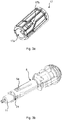
Fig. 6 is a perspective view of another example of a tubular extension member and plunger rod; -
Figs 7a and 7b are perspective views of the plunger rod and a U-bracket of the example inFig. 6 ; -
Fig. 8 is a perspective view of yet another example of a plunger rod and a U-bracket; and -
Figs 9a-9b show longitudinal section of a portion of a medicament delivery device comprising the plunger rod and U-bracket inFig. 8 in a state prior to use and during use, respectively. - The inventive concept will now be described more fully hereinafter with reference to the accompanying drawings, in which exemplifying embodiments are shown. The inventive concept may, however, be embodied in many different forms and should not be construed as limited to the embodiments set forth herein; rather, these embodiments are provided by way of example so that this disclosure will be thorough and complete, and will fully convey the scope of the inventive concept to those skilled in the art. Like numbers refer to like elements throughout the description.
- The medicament delivery device disclosed herein may for example a disposable single-use medicament delivery device, such as an auto-injector, an inhaler or an eye dispenser. The medicament delivery device may be a regular medicament delivery device for medicament administration, or a trainer device.
- The term "proximal end" as used herein refers to that end of a medicament delivery device at which medical expulsion can be provided. This is hence that end of the medicament delivery device that is to be pointed towards the injection or expulsion site. This definition also extends to any internal or external component of the medicament delivery device, i.e. the proximal end of any component is that which is closest to the proximal end of the medicament delivery device. The "distal end" is the opposite end relative to the proximal end. With "proximal direction" is meant a direction from the distal end towards the proximal end, along the central axis of the medicament delivery device. With "distal direction" is meant the opposite direction to "proximal direction".
- This disclosure concerns an automatic feedback mechanism for a medicament delivery device, and to a medicament delivery device with user feedback capabilities.
- The medicament delivery device has a housing having a proximal end and a distal end, a plunger rod received by the housing and axially displaceable from an initial position to a final position relative to the housing, a tubular extension member received by the housing and arranged to receive the plunger rod, which tubular extension member has a distal inner surface, a signal generating member received by the tubular extension member, wherein the plunger rod is arranged to be received by the signal generating member, and a first energy accumulation member arranged to bias the plunger rod in a proximal direction towards the proximal end and to bias the signal generating member in a distal direction which is opposite to the proximal direction.
- In the initial position the plunger rod, which in the initial position is in a pre-tensioned state, is arranged to flex or press the signal generating member radially outward towards the tubular extension member thereby engaging the signal generating member with the tubular extension member. To this end, the plunger rod has a first section with a first thickness or dimension, which presses the signal generating member which in the initial position is mounted around the plunger rod, radially outwards. The signal generating member is thereby engaged with the tubular extension member, retaining the distally biased signal generating member in a fixed axial position relative to the housing. In this axial position, the signal generating member is distanced from the distal inner surface of the tubular extension member.
- Prior to use, the plunger rod is arranged axially fixed in the initial position. When the medicament delivery device is activated, i.e. when a user initiates medicament delivery, the plunger rod is released from the initial position and is pressed in the proximal direction by the energy accumulation member. When the plunger rod has been displaced a distance corresponding to a distance necessary for commencement of medicament expulsion, the contact between the first section of the plunger rod and the signal generating member will cease. The plunger rod and the signal generating member are thus designed such that the axial overlap of the first section and signal generating member in the initial position of the plunger rod corresponds to, i.e. is equal to or essentially equal to, said distance. Hence, the first section only supports the signal generating member during axial displacement of the plunger rod distance corresponding to a distance necessary for commencement of medicament expulsion. When the plunger rod has been displaced by an amount corresponding to this distance, the signal generating member will be allowed to flex radially inwards towards its radially unbiased state. The signal generating member will thereby disengage from the tubular extension member. The signal generating member, which is biased in the distal direction by the first energy accumulation member will thereby no longer be retained by the tubular extension member and will therefore be thrown towards the distal inner surface of the tubular extension member. This results in an audible "click" sound and also provides the user with a tactile sensation.
- The medicament delivery device may furthermore comprise a medicament delivery member cover received by and rotationally interlocked with the housing, and a tubular rotator arranged to receive the plunger rod and the tubular extension member. The medicament delivery member cover is displaceable axially, between an extended position and a retracted relative to the housing. The medicament delivery member cover is biased towards the extended position.
- The tubular rotator is arranged to interact with the medicament delivery member and has a guide structure arranged to convert linear motion of the medicament delivery member to rotational motion of the tubular rotator.
-
Fig. 1 shows an example of a medicament delivery device. Themedicament delivery device 1 comprises ahousing 3, having aproximal end 3a and adistal end 3b, atubular extension member 5, for example a rear cap member, mounted at the distal end of thehousing 3, and a medicamentdelivery member cover 7, e.g. a needle cover, arranged to be received by thehousing 3 and arranged to be biased in the proximal direction. -
Fig. 2 depicts an exploded view of themedicament delivery device 1. Themedicament delivery device 1 further comprises aplunger rod 11 which is arranged to be biased towards theproximal end 3a, aplunger 13, a first resilient member, i.e. an energy accumulation member, 15 arranged to bias theplunger rod 11 in the proximal direction, which firstenergy accumulation member 15 may be a spring for example, a second resilient member or energy accumulation member 9, arranged to bias the medicamentdelivery member cover 7 in the proximal direction, atubular rotator 17 arranged to receive theplunger rod 11 and the firstenergy accumulation member 15,tubular extension member 5 which is axially and rotationally fixed relative to thehousing 3, atubular operation member 17, in the following referred to astubular rotator 17, arranged to receive a portion of therear end cap 7 and theplunger rod 11, arod 19 which the firstenergy accumulation member 15 is arranged to receive, and asignal generating member 21, which in the following will be exemplified by a U-shaped bracket, hereinafter referred to as "U-bracket". The exemplifiedmedicament delivery device 1 furthermore comprises amedicament container holder 23 and amedicament container 25 provided with aneedle 25a. Theplunger 13 is arranged to run in themedicament container 25 by linear displacement of theplunger rod 11, to thereby expel medicament through theneedle 25a. - The
plunger rod 11, thetubular extension member 5, thetubular operation member 17, theenergy accumulation member 15 and thesignal generating member 21 form an automatic feedback mechanism 12, or simply a feedback mechanism, for themedicament delivery device 1. Thefeedback mechanism 10 is arranged to notify a user of a start of expulsion of medicament from themedicament container 25. - According to the present example, the
plunger rod 11 has aradial opening 11a, and thetubular extension member 5 which is arranged to receive theplunger rod 11 has a correspondingflexible tongue 5a flexible in the radial direction and arranged to engage with theopening 11a. Thetubular rotator 17 is arranged to receive a portion of thetubular extension member 5, in particular that portion which comprises theflexible tongue 5a. - The
tubular rotator 17 is rotatable from an initial rotational position to a final rotational position. In its initial rotational position, thetubular rotator 17 is arranged to push theflexible tongue 5a into engagement with theopening 11a, preventing theplunger rod 11 from axial displacement. When thetubular rotator 17 is rotated, the inner structure of thetubular rotator 17 is designed such that it will provide less radial force on theflexible tongue 5a, allowing theflexible tongue 5a to flex radially outwards to disengage from theplunger rod 11. Theplunger rod 11, which is biased in the proximal direction, is thereby displaced axially and medicament administration is thus commenced as theplunger rod 15 pushes theplunger 13 inside themedicament container 25. - As shown in
Fig. 3a , thetubular rotator 17 has a central through-opening 17a extending from the proximal end to the distal end of thetubular rotator 17. Thetubular rotator 17 is arranged to receive thetubular extension member 5 and theplunger rod 11 in the through-opening 17a. - The
tubular rotator 17 furthermore comprises aguide structure 17b. Theguide structure 17b is arranged to interact with the medicamentdelivery member cover 7, in particular to convert linear motion of the medicamentdelivery member cover 7 to rotational motion of thetubular rotator 17. -
Fig. 4a shows a first example of aplunger rod 11, andU-bracket 21. The U-bracket 21 has a distaltransversal end portion 21a and twolegs 21b connected by the distaltransversal end portion 21a. Moreover, the U-bracket 21 has tworadial feet 21c. Eachradial foot 21c extends from arespective leg 21b. - The
plunger rod 11 has ahollow body 11b and adistal end opening 11c. Theplunger rod 11 is arranged to receive the firstenergy accumulation member 15 in thedistal end opening 11c, such that the firstenergy accumulation member 15 extends in the distal direction out from thedistal end opening 11d. Theplunger rod 11 is arranged to retain the proximal end of the firstenergy accumulation member 15 in thehollow body 11b to enable biasing by means of the firstenergy accumulation member 15. The U-bracket 21 is arranged to receive theplunger rod 11, from the distal end of theplunger rod 11, and the firstenergy accumulation member 15 is arranged to be compressed between the distaltransverse end portion 21a and a stop inside theplunger rod 11 when theplunger rod 11 is in the initial position. In the initial position of theplunger rod 11, theradial feet 21c are in engagement with therear end cap 5. - The exemplified
plunger rod 11 has an external surface that has afirst section 12a provided with afirst guide structure 11d arranged to support the U-bracket 21 and flex the U-bracket 21 radially outwards to enable theradial feet 21c to engage with thetubular extension member 5. Thefirst section 12a, and in particular thefirst guide structure 11d, has a dimension in the transverse direction perpendicular to the longitudinal direction of theplunger rod 11, which is greater than the distance between the tworadial feet 21c in a radially unbiased state of the U-bracket 21. Thefirst guide structure 11d hence pushes the U-bracket 21 radially outwards when the U-bracket bears against thefirst guide structure 11d. Thefirst guide structure 11d includes axial grooves, of which only one is shown inFig. 4a ; the other one being at 180 degrees relative to the illustrated axial groove. Thefirst guide structure 11d facilitates guiding relative linear movement between theplunger rod 11 and the U-bracket. In particular, thelegs 21b are arranged to slide in theaxial grooves 11d. - In the initial position of the
plunger rod 11 the axial overlap of thefirst section 12a, in particular thefirst guide structure 11d, and the U-bracket 21 corresponds to the distance of axial displacement of theplunger rod 11 necessary for commencement of medicament expulsion. This distance corresponds to the distance from the proximal end of theplunger rod 11 to the distal end of theplunger 13, in the initial position of theplunger rod 11. The initial overlap may be a little longer or a little shorter than the distance from the proximal end of the plunger rod to the distal end of the plunger. This applies to any variation disclosed herein. - The
plunger rod 11 has asecond section 12b arranged distally from and contiguous to thefirst section 12a. According to the present example, thesecond section 12b is defined by a longitudinal axially extendingradial opening 11e allowing radial inwards flexing of the U-bracket 21 towards its radially unbiased state. To this end, in thesecond section 12b the channel forming thedistal end opening 11c is open to the sides, i.e. in the radial direction. The longitudinal axially extendingradial opening 11e has a longitudinal extension aligned with thefirst guide structure 11d. The transverse dimension of theplunger rod 11 is here due to the longitudinal axially extendingradial opening 11d smaller than it is in thefirst section 12a. The U-bracket 21 is allowed to flex radially inwards towards its radially unbiased state, only limited by the diameter of the firstenergy accumulation member 15. This radial inwards flexing of the U-bracket 21 is sufficient to disengage theradial feet 21c from therear end cap 5. - The exemplified
plunger rod 11 furthermore has a third section 12c arranged distally from and contiguous to thesecond section 12b. The third section 12c is defined by asecond guide structure 11f arranged to guide the U-bracket 21 axially. Thesecond guide structure 11f is axially aligned with the longitudinal extendingradial opening 11e. Thesecond guide structure 11f may for example comprise two axial grooves, of which one is shown inFig 4a . Thesecond guide structure 11f has a greater transverse dimension than the longitudinal axially extendingradial opening 11d. To this end, the third section 12c is arranged to support and flex the U-bracket 21 radially outwards allowing the U-bracket to again engage with thetubular extension member 5. -
Fig. 4b shows theplunger rod 11 and the U-bracket 21 in a mounted state, i.e. when the U-bracket 21 has received theplunger rod 11. This is in particular their relative position in the initial position of theplunger rod 11. It may be seen that the firstenergy accumulation member 15 is in a compressed state in which it biases theplunger rod 11 in the proximal direction and the U-bracket 21 in the distal direction. It should here be noted that this compressed state is obtained when theplunger rod 11 is prevented from axial displacement by engagement with theflexible tongue 5a of thetubular extension member 5 and the U-bracket 21 is in engagement with thetubular extension member 5. - With reference to
Figs 5a-c the operation of theplunger rod 11 and the U-bracket 21 will now be described in more detail. InFig. 5a themedicament delivery device 1 is in a state ready for use. Theplunger rod 11 is in the initial position. The U-bracket 21 is in a first position in which it bears against thefirst section 12a, in particular thefirst guide structure 11d. The U-bracket 21 is hence flexed radially and in engagement with thetubular extension member 5. Thetubular extension member 5 has first engagement means 5c for engagement with the U-bracket 21. The first engagement means 5c may for example be a proximal end edge of thetubular extension member 5 or radial recess, with which theradial feet 21c may engage. The firstenergy accumulation member 15 is hence in a compressed state, biasing theplunger rod 11 and the U-bracket 21 in opposite directions. Thetubular extension member 5 has a distalinner surface 5b defining a distal end of the central opening of thetubular extension member 5 in which theplunger rod 11 and the U-bracket 21 are arranged. The U-bracket 21 is distanced by distance D from the distalinner surface 5b. - The
plunger rod 11 and theplunger 13 are in contact with each other in the initial position of theplunger rod 11. There is however a play, or distance d, between theplunger rod 11 and the distal end of theplunger 13. Theplunger rod 11 has to be displaced the distance d before it can displace theplunger 13 axially. This distance d corresponds to the distance that theplunger rod 11 must travel in order for medicament expulsion to commence. This is also the size of the axial overlap of thefirst section 12a and the U-bracket 21 in the initial position of theplunger rod 11. - In
Fig. 5b , themedicament delivery device 1 is shown during medicament expulsion. Here, theplunger rod 11 has been released from engagement with thetubular extension member 5 due to the rotation of thetubular rotator 17. In the illustration inFig. 5b , theplunger rod 11 has been displaced in the proximal direction and it has bridged the initial gap, or distance d, to theplunger 13. Medicament expulsion has hence commenced. The U-bracket 21 has moreover been released from its initial engagement with therear end cap 5, as the displacement of theplunger rod 11 has resulted in that thesecond section 12b of theplunger rod 11 has reached the proximal end of the U-bracket 21, whereby the U-bracket 21 has been able to flex radially inwards towards its radially unbiased position. The U-bracket 21 has thus been rapidly displaced in the distal direction until reaching the distalinner surface 5b of thetubular extension member 5. The opposite directional motion of theplunger rod 11 and the U-bracket 21 is generally shown by the two arrows. This collision results in an audible "click", and in vibration of themedicament delivery device 1. The user hence becomes aware of that medicament expulsion has commenced. The user may then, for example, count 10-15 seconds before removing themedicament delivery device 1 from the injection site. - The U-bracket 21 may in its end position in which it has collided with the distal
inner surface 5b, engage with thetubular extension member 5. Thetubular extension member 5 may therefore haveradial openings 5d arranged distally from and aligned with the first engagement means 5c. In particular, theradial feet 21c may be received in theradial openings 5d to enable theplunger rod 11 to move past the U-bracket 21 during medicament expulsion, in particular as the third section 12c passes by the proximal end of the U-bracket 21.Fig. 5c shows themedicament delivery device 1 in a final state, after medicament delivery has been finalised and theplunger rod 11 has moved past the U-bracket 21 in the proximal direction. -
Fig. 6 shows a second example of atubular extension member 5 and a plunger rod 11-1.Fig. 7a shows the plunger rod 11-1 in more detail. Plunger rod 11-1 is similar to the previously describedplunger rod 11. Plunger rod 11-1 also has afirst section 12a likeplunger rod 11, i.e. with afirst guide structure 11d. Plunger rod 11-1 however has asecond section 12b arranged distally from and contiguous to thefirst section 12a, which second section extends to thedistal end 14 of the plunger rod 11-1. Thesecond section 12b is also in this example defined by a longitudinal axially extendingradial opening 11e allowing radial inwards flexing of the U-bracket 21 towards its radially unbiased state. To this end, in thesecond section 12b may be formed by two axial cut-outs extending from thedistal end 14 of the plunger rod 11-1 tofirst section 12a, splitting the distal portion of the plunger rod 11-1. The longitudinal axially extendingradial opening 11e has a longitudinal extension aligned with thefirst guide structure 11d. The transverse dimension of theplunger rod 11 is due to the longitudinal axially extendingradial opening 11d smaller than it is in thefirst section 12a. The U-bracket 21 is here allowed to flex radially inwards towards its radially unbiased state, only limited by the diameter of the firstenergy accumulation member 15. This radial inwards flexing of the U-bracket 21 is sufficient to disengage theradial feet 21c from therear end cap 5. - The operation of this variation of the
medicament delivery device 1 is similar to that described above with reference toFigs 5a-c . Thetubular extension member 5 does however not have radial openings arranged distally from the first engagement means in order to enable the plunger rod 11-1 to pass the U-bracket 21. Since the opensecond section 12b of plunger rod 11-1 extends until thedistal end 14, the U-bracket 21 can be accommodated in the longitudinal axially extending radial opening the entire way as the plunger rod 11-1 moves past the U-bracket 21.Fig. 7b shows the plunger rod 11-1 and the U-bracket 21 in an assembled state. - With reference to
Fig. 8 another example of a plunger rod and U-bracket is shown. According to this variation, the U-bracket 21-1 is shorter relative to the plunger rod 11-2 than the U-bracket 21 is relative to theplunger rods 11 and 11-1. Plunger rod 11-2 is adapted to the design of U-bracket 21-1. To this end, plunger rod 11-2 has an external surface that has afirst section 12a provided with afirst guide structure 11d arranged to support the U-bracket 21-1 and flex the U-bracket 21-1 radially outwards to enable theradial feet 21c to engage with thetubular extension member 5. Thefirst section 12a, and in particular thefirst guide structure 11d, has a dimension in the transverse direction perpendicular to the longitudinal direction of the plunger rod 11-2, is greater than the distance between theradial feet 21c in the radially unbiased state of the U-bracket 21-1. Thefirst guide structure 11d hence pushes the U-bracket 21-1 radially outwards when the U-bracket bears against thefirst section 12a. - The
first guide structure 11d includes axial grooves, of which only one is shown inFig. 8 . Thefirst guide structure 11d facilitates guiding relative linear movement between the plunger rod 11-2 and the U-bracket 21-1. - The
first section 12a extends the entire way to thedistal end 14 of the plunger rod 11-2. In the initial position of the plunger rod 11-2 the axial overlap between thefirst section 12a and the U-bracket 21-1 corresponds to the distance of axial displacement of the plunger rod 11-2 necessary for commencement of medicament expulsion -
Figs 9a-9b show the operation of amedicament delivery device 1 including the plunger rod 11-2 and the U-bracket 21-1. The tubular extension member 5-1 has first engagement means 5c, which in the present case are exemplified by radial openings. As shown inFig. 9a theradial feet 21c of the U-bracket 21-1 are initially, i.e. in the initial position of the plunger rod 11-2, in engagement with the radial openings. When the plunger rod 11-2 is released by rotation of thetubular rotator 17, the plunger rod 11-2 is displaced in the proximal direction bridging the gap d between the distal end of theplunger 13 and the proximal end of the plunger rod 11-2. The plunger rod 11-2 will thus generally have been displaced enough to slide out beneath the U-bracket 21-1 to thereby allow the U-bracket 21 to flex radially inwards towards its radially unbiased state. The U-bracket 21 is hence disengaged from the tubular extension member 5-1 and is thereby due to its biased state rapidly displaced in the distal direction, subsequently colliding with the distalinner surface 5b of the tubular extension member 5-1. Again, audible "click" is thereby generated, and vibrations are induced in themedicament delivery device 1.Fig. 9b shows when the U-bracket 21 has collided with the distalinner surface 5b. - Any variation disclosed herein may be utilised with an electromechanical sensor and a recording unit provided with electronic components, and which recording unit may be attachable to and detachable from the housing. The electromechanical sensor may be arranged to detect when the U-bracket collides with the distal inner surface. According to this variation the medicament delivery device includes an injection end member which is axially displaceable and arranged to interact with the U-bracket. The tubular extension member has a distal through-opening in which the injection end member is movably arranged. When medicament expulsion commences, the U-bracket is released and due to the biasing provided by the first energy accumulation member, is pushed in the distal direction. As a result, the injection end member which is axially aligned and located distally relative to the U-bracket, is pushed axially in the distal direction by the U-bracket, as allowed by its free location in the distal through-opening. The injection end member will thereby actuate the electromechanical sensor arranged to detect displacement of the injection end member when medicament expulsion is commenced. In this manner detection of commencement of medicament expulsion may be presented to the user by the recording unit or by an external device in communication with the recording unit.
- The inventive concept has mainly been described above with reference to a few examples. However, as is readily appreciated by a person skilled in the art, other embodiments than the ones disclosed above are equally possible within the scope of the inventive concept, as defined by the appended claims.
Claims (15)
- An automatic feedback mechanism (10) for a medicament delivery device (1), which notifies a user of a start of expulsion of medicament from a medicament container, wherein the automatic feedback mechanism (10) comprises:a plunger rod (11; 11-1; 11-2),a tubular extension member (5) having a radial space defined by an inner perimeter and an inner distal surface (5b), wherein the tubular extension member (5) is arranged to receive the plunger rod (11; 11-1; 11-2) in the radial space, and wherein the tubular extension member (5) has flexible tongues (5a) configured to releasably lock the plunger rod (11; 11-1; 11-2) in a pre-tensioned state,a tubular operation member (17) arranged to receive the tubular extension member (5), which tubular operation member (17) is movable relative to the tubular extension member (5), wherein the tubular operation member (17) in a first position is arranged to press the flexible tongues (5a) radially inwards to lock the plunger rod (11; 11-1; 11-2) in the pre-tensioned state,a first resilient member (15) arranged to be received inside the plunger rod (11; 11-1; 11-2) to exert a force in the proximal direction, anda signal generating member (21; 21-1) arranged to partially surround the plunger rod (11; 11-1; 11-2) and having a distal transversal end portion (21a) which in a first position is at a distance D from the inner distal surface (5a) of the tubular extension member (5) when the plunger rod (11; 11-1; 11-2) is in the pre-tensioned state,wherein in an assembled state, movement of the tubular operation member (17) causes the flexible tongues (5a) to expand radially releasing the plunger rod (11; 11-1; 11-2) to travel proximally and allowing the first resilient member (15) to move the signal generating member (21; 21-1) distally the distance D such that the distal transversal end portion (21a) hits the inner distal surface (5b) generating an audible signal.
- The feedback mechanism (10) as claimed in claim 1 wherein the signal generating member (21; 21-1) comprises an elongated U-shaped bracket having two longitudinally extending flexible legs (21b) provided with angled radial feet (21c) extending radially outward to secure the signal generating member (21; 21-1) in the first position.
- The feedback mechanism (10) as claimed in claim 2 wherein the radial feet (21c) in the first position have a radial extension that exceeds the transverse dimension of the radial space of the tubular extension member (5) and where the radial feet (21c) in a second position have a radial extension that is less than the transverse dimension of the radial space of the tubular extension member (5).
- The feedback mechanism (10) as claimed in claim 3 wherein the radial feet (21c) in the first position have a radial extension that exceeds the radial extension of the radial feet (21c) when in the second position.
- The feedback mechanism (10) as claimed in any of the preceding claims, wherein the plunger rod has an external surface which has a first section (12a) provided with a first guide structure (11d) arranged to support and flex the signal generating member (21; 21-1) radially outwards, and to guide axial displacement of the signal generating member (21; 21-1).
- The feedback mechanism (10) as claimed in claim 5, wherein in the initial position of the plunger rod (11; 11-1; 11-2) the axial overlap between the first section (12a) and the signal generating member (21; 21-1) corresponds to the distance of axial displacement of the plunger rod (11; 11-1; 11-2) necessary for commencement of medicament expulsion.
- The feedback mechanism (10) as claimed in claim 5 or 6, wherein the signal generating member (21; 21-1) has legs (21b) arranged to interact with the first guide structure (11d).
- The feedback mechanism (10) as claimed in any of claims 5-7, wherein the first guide structure (11d) comprises axial grooves in which the signal generating member (21; 21-1) is arranged to slide.
- The feedback mechanism (10) as claimed in any of claims 5-8, wherein the plunger rod (11; 11-1; 11-2) has a second section (12b) arranged distally from and contiguous to the first section (12a), which second section (12b) is defined by a longitudinal axially extending radial opening (11e) axially aligned with the first guide structure (11d), allowing radial inwards flexing of the signal generating member (21; 21-1) towards its radially unbiased state.
- The feedback mechanism (10) as claimed in claim 9, wherein the second section (12b) extends to the distal end (14) of the plunger rod (11-1).
- The feedback mechanism (10) as claimed in claim 9, wherein the plunger rod (11) has a third section (12c) arranged distally from and contiguous to the second section (12b), which third section (12c) is defined by a second guide structure (11f) axially aligned with the longitudinal axially extending radial opening (11e), and arranged to support and flex the signal generating member (21) radially outwards.
- The feedback mechanism (10) as claimed in claim 11, wherein the tubular extension member (5) has first engagement means (5c) for engaging with the signal generating member (21) in the initial position of the plunger rod (11), and wherein the tubular extension member (5) has radial openings (5d) arranged distally from and aligned with the first engagement means (5c), for allowing the signal generating member (21) to flex radially outwards.
- The feedback mechanism (10) as claimed in any of claims 1-8, wherein the first section (12a) extends to the distal end (14) of the plunger rod (21-1).
- A medicament delivery device (1) comprising a feedback mechanism as claimed in any of claims 1-13.
- A medicament delivery device of claim 14, comprising a linearly displaceable medicament delivery member cover (7) configured to interact with the tubular operation member (17).
Applications Claiming Priority (3)
| Application Number | Priority Date | Filing Date | Title |
|---|---|---|---|
| EP16155880.4A EP3207952A1 (en) | 2016-02-16 | 2016-02-16 | An automatic feedback mechanism and a medicament delivery device with user feedback capability |
| PCT/EP2017/051039 WO2017140452A1 (en) | 2016-02-16 | 2017-01-19 | An automatic feedback mechanism and a medicament delivery device with user feedback capability |
| EP17700565.9A EP3416706B1 (en) | 2016-02-16 | 2017-01-19 | An automatic feedback mechanism and a medicament delivery device with user feedback capability |
Related Parent Applications (2)
| Application Number | Title | Priority Date | Filing Date |
|---|---|---|---|
| EP17700565.9A Division EP3416706B1 (en) | 2016-02-16 | 2017-01-19 | An automatic feedback mechanism and a medicament delivery device with user feedback capability |
| EP17700565.9A Division-Into EP3416706B1 (en) | 2016-02-16 | 2017-01-19 | An automatic feedback mechanism and a medicament delivery device with user feedback capability |
Publications (2)
| Publication Number | Publication Date |
|---|---|
| EP3701983A1 true EP3701983A1 (en) | 2020-09-02 |
| EP3701983B1 EP3701983B1 (en) | 2023-08-02 |
Family
ID=55411223
Family Applications (3)
| Application Number | Title | Priority Date | Filing Date |
|---|---|---|---|
| EP16155880.4A Withdrawn EP3207952A1 (en) | 2016-02-16 | 2016-02-16 | An automatic feedback mechanism and a medicament delivery device with user feedback capability |
| EP17700565.9A Active EP3416706B1 (en) | 2016-02-16 | 2017-01-19 | An automatic feedback mechanism and a medicament delivery device with user feedback capability |
| EP20171588.5A Active EP3701983B1 (en) | 2016-02-16 | 2017-01-19 | An automatic feedback mechanism and a medicament delivery device with user feedback capability |
Family Applications Before (2)
| Application Number | Title | Priority Date | Filing Date |
|---|---|---|---|
| EP16155880.4A Withdrawn EP3207952A1 (en) | 2016-02-16 | 2016-02-16 | An automatic feedback mechanism and a medicament delivery device with user feedback capability |
| EP17700565.9A Active EP3416706B1 (en) | 2016-02-16 | 2017-01-19 | An automatic feedback mechanism and a medicament delivery device with user feedback capability |
Country Status (7)
| Country | Link |
|---|---|
| US (2) | US11116910B2 (en) |
| EP (3) | EP3207952A1 (en) |
| JP (1) | JP6775028B2 (en) |
| KR (1) | KR102059765B1 (en) |
| CN (1) | CN108697851B (en) |
| TW (1) | TWI642456B (en) |
| WO (1) | WO2017140452A1 (en) |
Families Citing this family (27)
| Publication number | Priority date | Publication date | Assignee | Title |
|---|---|---|---|---|
| CN112188906B (en) | 2018-05-24 | 2023-10-27 | 诺华股份有限公司 | Automatic drug delivery device |
| EP3990055A1 (en) * | 2019-06-26 | 2022-05-04 | SHL Medical AG | Drive mechanism for a medicament delivery training device |
| WO2021110344A1 (en) | 2019-12-05 | 2021-06-10 | Shl Medical Ag | Feedback mechanisms |
| KR102676491B1 (en) | 2023-02-09 | 2024-06-21 | 주식회사 비에스엘 | Auto-injector |
| KR102676490B1 (en) | 2023-02-15 | 2024-06-21 | 주식회사 비에스엘 | Auto-injector |
| KR102682089B1 (en) | 2023-02-15 | 2024-07-05 | 주식회사 비에스엘 | Auto-injector |
| KR102694749B1 (en) | 2023-04-05 | 2024-08-14 | 주식회사 비에스엘 | Auto-injector |
| KR102682086B1 (en) | 2023-04-04 | 2024-07-05 | 주식회사 비에스엘 | Auto-injector |
| KR102694740B1 (en) * | 2023-03-29 | 2024-08-14 | 주식회사 비에스엘 | Auto-injector |
| KR102694750B1 (en) * | 2023-03-30 | 2024-08-14 | 주식회사 비에스엘 | Auto-injector with auditory feedback |
| KR102682092B1 (en) | 2023-04-05 | 2024-07-05 | 주식회사 비에스엘 | Trigger structure of auto-injector |
| KR102694738B1 (en) | 2023-04-10 | 2024-08-14 | 주식회사 비에스엘 | Auto-injector |
| KR102754390B1 (en) | 2023-04-10 | 2025-01-21 | 주식회사 비에스엘 | Auto-injector |
| KR102694747B1 (en) | 2023-04-11 | 2024-08-14 | 주식회사 비에스엘 | Auto-injector |
| KR102694755B1 (en) | 2023-04-11 | 2024-08-14 | 주식회사 비에스엘 | Auto-injector |
| KR20240166161A (en) | 2023-05-17 | 2024-11-26 | 주식회사 비에스엘 | Auto-injector |
| KR20240168676A (en) | 2023-05-23 | 2024-12-02 | 주식회사 비에스엘 | Auto-injector |
| KR20240172399A (en) | 2023-06-01 | 2024-12-10 | 주식회사 비에스엘 | Auto-injector |
| KR20240172400A (en) | 2023-06-01 | 2024-12-10 | 주식회사 비에스엘 | Auto-injector having auditory feedback member |
| KR20240176166A (en) | 2023-06-15 | 2024-12-24 | 주식회사 비에스엘 | Auto-injector |
| KR20240178748A (en) | 2023-06-23 | 2024-12-31 | 주식회사 비에스엘 | Auto-injector |
| KR20240178746A (en) | 2023-06-23 | 2024-12-31 | 주식회사 비에스엘 | Temporary assembly for medicament container of auto-injector |
| KR20250001230A (en) | 2023-06-28 | 2025-01-06 | 주식회사 비에스엘 | Auto-injector |
| KR20250002885A (en) | 2023-06-30 | 2025-01-07 | 주식회사 비에스엘 | Auto-injector |
| USD1049369S1 (en) * | 2023-09-25 | 2024-10-29 | Amgen Inc. | Handheld drug delivery device |
| USD1051367S1 (en) * | 2023-09-25 | 2024-11-12 | Amgen Inc. | Handheld drug delivery device |
| USD1050422S1 (en) * | 2023-09-25 | 2024-11-05 | Amgen Inc. | Handheld drug delivery device |
Citations (3)
| Publication number | Priority date | Publication date | Assignee | Title |
|---|---|---|---|---|
| WO2011099918A1 (en) * | 2010-02-09 | 2011-08-18 | Shl Group Ab | Medicament delivery device |
| WO2011123024A1 (en) * | 2010-03-31 | 2011-10-06 | Shl Group Ab | Medicament delivery device comprising feedback signalling means |
| EP2823841A1 (en) * | 2013-07-09 | 2015-01-14 | Sanofi-Aventis Deutschland GmbH | Autoinjector |
Family Cites Families (7)
| Publication number | Priority date | Publication date | Assignee | Title |
|---|---|---|---|---|
| EP2393533B1 (en) | 2009-02-05 | 2015-03-25 | Sanofi-Aventis Deutschland GmbH | Medicament delivery devices |
| JP5785190B2 (en) | 2009-12-22 | 2015-09-24 | ユニトラクト シリンジ プロプライエタリイ リミテッドUnitract Syringe Pty Ltd | Retractable syringe with locking system for improved transport efficiency |
| TWI517871B (en) | 2011-04-01 | 2016-01-21 | 泰博科技股份有限公司 | Injector |
| JP6257601B2 (en) * | 2012-05-31 | 2018-01-10 | ケアベイ・ヨーロッパ・リミテッドCarebay Europe Limited | Drug delivery device |
| EP3590568A1 (en) | 2013-03-22 | 2020-01-08 | TecPharma Licensing AG | Substance dispensing device with a signalling device |
| TWI569841B (en) * | 2013-10-10 | 2017-02-11 | 卡貝歐洲有限公司 | Medicament delivery device |
| EP3184134A1 (en) * | 2015-12-21 | 2017-06-28 | Carebay Europe Ltd. | Tubular rotator for a medicament delivery device and a medicament delivery device comprising the same |
-
2016
- 2016-02-16 EP EP16155880.4A patent/EP3207952A1/en not_active Withdrawn
-
2017
- 2017-01-19 EP EP17700565.9A patent/EP3416706B1/en active Active
- 2017-01-19 EP EP20171588.5A patent/EP3701983B1/en active Active
- 2017-01-19 WO PCT/EP2017/051039 patent/WO2017140452A1/en active Application Filing
- 2017-01-19 US US16/076,264 patent/US11116910B2/en active Active
- 2017-01-19 JP JP2018543235A patent/JP6775028B2/en active Active
- 2017-01-19 CN CN201780010847.XA patent/CN108697851B/en active Active
- 2017-01-19 KR KR1020187023471A patent/KR102059765B1/en active IP Right Grant
- 2017-01-24 TW TW106102672A patent/TWI642456B/en active
-
2021
- 2021-08-02 US US17/391,865 patent/US11724040B2/en active Active
Patent Citations (3)
| Publication number | Priority date | Publication date | Assignee | Title |
|---|---|---|---|---|
| WO2011099918A1 (en) * | 2010-02-09 | 2011-08-18 | Shl Group Ab | Medicament delivery device |
| WO2011123024A1 (en) * | 2010-03-31 | 2011-10-06 | Shl Group Ab | Medicament delivery device comprising feedback signalling means |
| EP2823841A1 (en) * | 2013-07-09 | 2015-01-14 | Sanofi-Aventis Deutschland GmbH | Autoinjector |
Also Published As
| Publication number | Publication date |
|---|---|
| US11116910B2 (en) | 2021-09-14 |
| TWI642456B (en) | 2018-12-01 |
| JP6775028B2 (en) | 2020-10-28 |
| CN108697851A (en) | 2018-10-23 |
| TW201731544A (en) | 2017-09-16 |
| US20210170108A1 (en) | 2021-06-10 |
| EP3416706A1 (en) | 2018-12-26 |
| US20210361878A1 (en) | 2021-11-25 |
| US11724040B2 (en) | 2023-08-15 |
| CN108697851B (en) | 2021-05-25 |
| EP3207952A1 (en) | 2017-08-23 |
| KR102059765B1 (en) | 2020-02-11 |
| JP2019509093A (en) | 2019-04-04 |
| EP3701983B1 (en) | 2023-08-02 |
| KR20180103998A (en) | 2018-09-19 |
| EP3416706B1 (en) | 2020-06-10 |
| WO2017140452A1 (en) | 2017-08-24 |
Similar Documents
| Publication | Publication Date | Title |
|---|---|---|
| US11724040B2 (en) | Automatic feedback mechanism and a medicament delivery device with user feedback capability | |
| US20240173482A1 (en) | Drive assembly for a medicament delivery device | |
| US11087640B2 (en) | Medicament delivery training device | |
| EP3484548B1 (en) | Administration mechanism for a medicament delivery device | |
| EP3458128B1 (en) | Administration mechanism for a medicament delivery device | |
| JP6944508B2 (en) | Drug delivery device | |
| WO2020259997A1 (en) | Drive mechanism for a medicament delivery training device | |
| KR20170139636A (en) | Driving mechanism for automatic syringe | |
| EP3548118B1 (en) | A feedback element for a medicament delivery device | |
| EP3423131B1 (en) | Automatic delivery device with end of injection indication device | |
| US20220208024A1 (en) | Drive mechanism for a resettable medicament delivery training device | |
| TWI569844B (en) | Medicament delivery device | |
| JP2024535604A (en) | Subassembly for a drug delivery device - Patent application | |
| CN117715671A (en) | Slider and subassembly for a medicament delivery device | |
| WO2023066677A1 (en) | Automatic feedback mechanism for a medicament delivery device |
Legal Events
| Date | Code | Title | Description |
|---|---|---|---|
| PUAI | Public reference made under article 153(3) epc to a published international application that has entered the european phase |
Free format text: ORIGINAL CODE: 0009012 |
|
| STAA | Information on the status of an ep patent application or granted ep patent |
Free format text: STATUS: THE APPLICATION HAS BEEN PUBLISHED |
|
| AC | Divisional application: reference to earlier application |
Ref document number: 3416706 Country of ref document: EP Kind code of ref document: P |
|
| AK | Designated contracting states |
Kind code of ref document: A1 Designated state(s): AL AT BE BG CH CY CZ DE DK EE ES FI FR GB GR HR HU IE IS IT LI LT LU LV MC MK MT NL NO PL PT RO RS SE SI SK SM TR |
|
| STAA | Information on the status of an ep patent application or granted ep patent |
Free format text: STATUS: REQUEST FOR EXAMINATION WAS MADE |
|
| 17P | Request for examination filed |
Effective date: 20210222 |
|
| RBV | Designated contracting states (corrected) |
Designated state(s): AL AT BE BG CH CY CZ DE DK EE ES FI FR GB GR HR HU IE IS IT LI LT LU LV MC MK MT NL NO PL PT RO RS SE SI SK SM TR |
|
| GRAP | Despatch of communication of intention to grant a patent |
Free format text: ORIGINAL CODE: EPIDOSNIGR1 |
|
| STAA | Information on the status of an ep patent application or granted ep patent |
Free format text: STATUS: GRANT OF PATENT IS INTENDED |
|
| RIC1 | Information provided on ipc code assigned before grant |
Ipc: A61M 5/20 20060101AFI20230427BHEP |
|
| P01 | Opt-out of the competence of the unified patent court (upc) registered |
Effective date: 20230425 |
|
| INTG | Intention to grant announced |
Effective date: 20230525 |
|
| GRAS | Grant fee paid |
Free format text: ORIGINAL CODE: EPIDOSNIGR3 |
|
| GRAA | (expected) grant |
Free format text: ORIGINAL CODE: 0009210 |
|
| STAA | Information on the status of an ep patent application or granted ep patent |
Free format text: STATUS: THE PATENT HAS BEEN GRANTED |
|
| AC | Divisional application: reference to earlier application |
Ref document number: 3416706 Country of ref document: EP Kind code of ref document: P |
|
| AK | Designated contracting states |
Kind code of ref document: B1 Designated state(s): AL AT BE BG CH CY CZ DE DK EE ES FI FR GB GR HR HU IE IS IT LI LT LU LV MC MK MT NL NO PL PT RO RS SE SI SK SM TR |
|
| REG | Reference to a national code |
Ref country code: GB Ref legal event code: FG4D |
|
| REG | Reference to a national code |
Ref country code: CH Ref legal event code: EP |
|
| REG | Reference to a national code |
Ref country code: DE Ref legal event code: R096 Ref document number: 602017072357 Country of ref document: DE |
|
| REG | Reference to a national code |
Ref country code: IE Ref legal event code: FG4D |
|
| REG | Reference to a national code |
Ref country code: LT Ref legal event code: MG9D |
|
| REG | Reference to a national code |
Ref country code: NL Ref legal event code: MP Effective date: 20230802 |
|
| REG | Reference to a national code |
Ref country code: AT Ref legal event code: MK05 Ref document number: 1593926 Country of ref document: AT Kind code of ref document: T Effective date: 20230802 |
|
| PG25 | Lapsed in a contracting state [announced via postgrant information from national office to epo] |
Ref country code: GR Free format text: LAPSE BECAUSE OF FAILURE TO SUBMIT A TRANSLATION OF THE DESCRIPTION OR TO PAY THE FEE WITHIN THE PRESCRIBED TIME-LIMIT Effective date: 20231103 |
|
| PG25 | Lapsed in a contracting state [announced via postgrant information from national office to epo] |
Ref country code: IS Free format text: LAPSE BECAUSE OF FAILURE TO SUBMIT A TRANSLATION OF THE DESCRIPTION OR TO PAY THE FEE WITHIN THE PRESCRIBED TIME-LIMIT Effective date: 20231202 |
|
| PG25 | Lapsed in a contracting state [announced via postgrant information from national office to epo] |
Ref country code: SE Free format text: LAPSE BECAUSE OF FAILURE TO SUBMIT A TRANSLATION OF THE DESCRIPTION OR TO PAY THE FEE WITHIN THE PRESCRIBED TIME-LIMIT Effective date: 20230802 Ref country code: RS Free format text: LAPSE BECAUSE OF FAILURE TO SUBMIT A TRANSLATION OF THE DESCRIPTION OR TO PAY THE FEE WITHIN THE PRESCRIBED TIME-LIMIT Effective date: 20230802 Ref country code: PT Free format text: LAPSE BECAUSE OF FAILURE TO SUBMIT A TRANSLATION OF THE DESCRIPTION OR TO PAY THE FEE WITHIN THE PRESCRIBED TIME-LIMIT Effective date: 20231204 Ref country code: NO Free format text: LAPSE BECAUSE OF FAILURE TO SUBMIT A TRANSLATION OF THE DESCRIPTION OR TO PAY THE FEE WITHIN THE PRESCRIBED TIME-LIMIT Effective date: 20231102 Ref country code: NL Free format text: LAPSE BECAUSE OF FAILURE TO SUBMIT A TRANSLATION OF THE DESCRIPTION OR TO PAY THE FEE WITHIN THE PRESCRIBED TIME-LIMIT Effective date: 20230802 Ref country code: LV Free format text: LAPSE BECAUSE OF FAILURE TO SUBMIT A TRANSLATION OF THE DESCRIPTION OR TO PAY THE FEE WITHIN THE PRESCRIBED TIME-LIMIT Effective date: 20230802 Ref country code: LT Free format text: LAPSE BECAUSE OF FAILURE TO SUBMIT A TRANSLATION OF THE DESCRIPTION OR TO PAY THE FEE WITHIN THE PRESCRIBED TIME-LIMIT Effective date: 20230802 Ref country code: IS Free format text: LAPSE BECAUSE OF FAILURE TO SUBMIT A TRANSLATION OF THE DESCRIPTION OR TO PAY THE FEE WITHIN THE PRESCRIBED TIME-LIMIT Effective date: 20231202 Ref country code: HR Free format text: LAPSE BECAUSE OF FAILURE TO SUBMIT A TRANSLATION OF THE DESCRIPTION OR TO PAY THE FEE WITHIN THE PRESCRIBED TIME-LIMIT Effective date: 20230802 Ref country code: GR Free format text: LAPSE BECAUSE OF FAILURE TO SUBMIT A TRANSLATION OF THE DESCRIPTION OR TO PAY THE FEE WITHIN THE PRESCRIBED TIME-LIMIT Effective date: 20231103 Ref country code: FI Free format text: LAPSE BECAUSE OF FAILURE TO SUBMIT A TRANSLATION OF THE DESCRIPTION OR TO PAY THE FEE WITHIN THE PRESCRIBED TIME-LIMIT Effective date: 20230802 Ref country code: AT Free format text: LAPSE BECAUSE OF FAILURE TO SUBMIT A TRANSLATION OF THE DESCRIPTION OR TO PAY THE FEE WITHIN THE PRESCRIBED TIME-LIMIT Effective date: 20230802 |
|
| PG25 | Lapsed in a contracting state [announced via postgrant information from national office to epo] |
Ref country code: PL Free format text: LAPSE BECAUSE OF FAILURE TO SUBMIT A TRANSLATION OF THE DESCRIPTION OR TO PAY THE FEE WITHIN THE PRESCRIBED TIME-LIMIT Effective date: 20230802 |
|
| PG25 | Lapsed in a contracting state [announced via postgrant information from national office to epo] |
Ref country code: ES Free format text: LAPSE BECAUSE OF FAILURE TO SUBMIT A TRANSLATION OF THE DESCRIPTION OR TO PAY THE FEE WITHIN THE PRESCRIBED TIME-LIMIT Effective date: 20230802 |
|
| PG25 | Lapsed in a contracting state [announced via postgrant information from national office to epo] |
Ref country code: SM Free format text: LAPSE BECAUSE OF FAILURE TO SUBMIT A TRANSLATION OF THE DESCRIPTION OR TO PAY THE FEE WITHIN THE PRESCRIBED TIME-LIMIT Effective date: 20230802 Ref country code: RO Free format text: LAPSE BECAUSE OF FAILURE TO SUBMIT A TRANSLATION OF THE DESCRIPTION OR TO PAY THE FEE WITHIN THE PRESCRIBED TIME-LIMIT Effective date: 20230802 Ref country code: ES Free format text: LAPSE BECAUSE OF FAILURE TO SUBMIT A TRANSLATION OF THE DESCRIPTION OR TO PAY THE FEE WITHIN THE PRESCRIBED TIME-LIMIT Effective date: 20230802 Ref country code: EE Free format text: LAPSE BECAUSE OF FAILURE TO SUBMIT A TRANSLATION OF THE DESCRIPTION OR TO PAY THE FEE WITHIN THE PRESCRIBED TIME-LIMIT Effective date: 20230802 Ref country code: DK Free format text: LAPSE BECAUSE OF FAILURE TO SUBMIT A TRANSLATION OF THE DESCRIPTION OR TO PAY THE FEE WITHIN THE PRESCRIBED TIME-LIMIT Effective date: 20230802 Ref country code: CZ Free format text: LAPSE BECAUSE OF FAILURE TO SUBMIT A TRANSLATION OF THE DESCRIPTION OR TO PAY THE FEE WITHIN THE PRESCRIBED TIME-LIMIT Effective date: 20230802 Ref country code: SK Free format text: LAPSE BECAUSE OF FAILURE TO SUBMIT A TRANSLATION OF THE DESCRIPTION OR TO PAY THE FEE WITHIN THE PRESCRIBED TIME-LIMIT Effective date: 20230802 |
|
| PGFP | Annual fee paid to national office [announced via postgrant information from national office to epo] |
Ref country code: DE Payment date: 20231205 Year of fee payment: 8 Ref country code: CH Payment date: 20240201 Year of fee payment: 8 |
|
| REG | Reference to a national code |
Ref country code: DE Ref legal event code: R097 Ref document number: 602017072357 Country of ref document: DE |
|
| PG25 | Lapsed in a contracting state [announced via postgrant information from national office to epo] |
Ref country code: IT Free format text: LAPSE BECAUSE OF FAILURE TO SUBMIT A TRANSLATION OF THE DESCRIPTION OR TO PAY THE FEE WITHIN THE PRESCRIBED TIME-LIMIT Effective date: 20230802 |
|
| PLBE | No opposition filed within time limit |
Free format text: ORIGINAL CODE: 0009261 |
|
| STAA | Information on the status of an ep patent application or granted ep patent |
Free format text: STATUS: NO OPPOSITION FILED WITHIN TIME LIMIT |
|
| 26N | No opposition filed |
Effective date: 20240503 |
|
| PG25 | Lapsed in a contracting state [announced via postgrant information from national office to epo] |
Ref country code: SI Free format text: LAPSE BECAUSE OF FAILURE TO SUBMIT A TRANSLATION OF THE DESCRIPTION OR TO PAY THE FEE WITHIN THE PRESCRIBED TIME-LIMIT Effective date: 20230802 |
|
| PG25 | Lapsed in a contracting state [announced via postgrant information from national office to epo] |
Ref country code: MC Free format text: LAPSE BECAUSE OF FAILURE TO SUBMIT A TRANSLATION OF THE DESCRIPTION OR TO PAY THE FEE WITHIN THE PRESCRIBED TIME-LIMIT Effective date: 20230802 |
|
| PG25 | Lapsed in a contracting state [announced via postgrant information from national office to epo] |
Ref country code: MC Free format text: LAPSE BECAUSE OF FAILURE TO SUBMIT A TRANSLATION OF THE DESCRIPTION OR TO PAY THE FEE WITHIN THE PRESCRIBED TIME-LIMIT Effective date: 20230802 |
|
| PG25 | Lapsed in a contracting state [announced via postgrant information from national office to epo] |
Ref country code: LU Free format text: LAPSE BECAUSE OF NON-PAYMENT OF DUE FEES Effective date: 20240119 |
|
| PG25 | Lapsed in a contracting state [announced via postgrant information from national office to epo] |
Ref country code: LU Free format text: LAPSE BECAUSE OF NON-PAYMENT OF DUE FEES Effective date: 20240119 |
|
| PG25 | Lapsed in a contracting state [announced via postgrant information from national office to epo] |
Ref country code: BE Free format text: LAPSE BECAUSE OF NON-PAYMENT OF DUE FEES Effective date: 20240131 |
|
| PG25 | Lapsed in a contracting state [announced via postgrant information from national office to epo] |
Ref country code: BE Free format text: LAPSE BECAUSE OF NON-PAYMENT OF DUE FEES Effective date: 20240131 |
|
| REG | Reference to a national code |
Ref country code: BE Ref legal event code: MM Effective date: 20240131 |
|
| PG25 | Lapsed in a contracting state [announced via postgrant information from national office to epo] |
Ref country code: BG Free format text: LAPSE BECAUSE OF FAILURE TO SUBMIT A TRANSLATION OF THE DESCRIPTION OR TO PAY THE FEE WITHIN THE PRESCRIBED TIME-LIMIT Effective date: 20230802 |
|
| PG25 | Lapsed in a contracting state [announced via postgrant information from national office to epo] |
Ref country code: BG Free format text: LAPSE BECAUSE OF FAILURE TO SUBMIT A TRANSLATION OF THE DESCRIPTION OR TO PAY THE FEE WITHIN THE PRESCRIBED TIME-LIMIT Effective date: 20230802 |
|
| PGFP | Annual fee paid to national office [announced via postgrant information from national office to epo] |
Ref country code: GB Payment date: 20241205 Year of fee payment: 9 |
|
| PGFP | Annual fee paid to national office [announced via postgrant information from national office to epo] |
Ref country code: FR Payment date: 20241209 Year of fee payment: 9 |
|
| PG25 | Lapsed in a contracting state [announced via postgrant information from national office to epo] |
Ref country code: IE Free format text: LAPSE BECAUSE OF NON-PAYMENT OF DUE FEES Effective date: 20240119 |
|
| PG25 | Lapsed in a contracting state [announced via postgrant information from national office to epo] |
Ref country code: IE Free format text: LAPSE BECAUSE OF NON-PAYMENT OF DUE FEES Effective date: 20240119 |