EP2823732B1 - Möbelsystem mit einem Möbelelement - Google Patents
Möbelsystem mit einem Möbelelement Download PDFInfo
- Publication number
- EP2823732B1 EP2823732B1 EP14175922.5A EP14175922A EP2823732B1 EP 2823732 B1 EP2823732 B1 EP 2823732B1 EP 14175922 A EP14175922 A EP 14175922A EP 2823732 B1 EP2823732 B1 EP 2823732B1
- Authority
- EP
- European Patent Office
- Prior art keywords
- opening
- furniture
- cable channel
- furniture system
- cable
- Prior art date
- Legal status (The legal status is an assumption and is not a legal conclusion. Google has not performed a legal analysis and makes no representation as to the accuracy of the status listed.)
- Active
Links
Images


Classifications
-
- A—HUMAN NECESSITIES
- A47—FURNITURE; DOMESTIC ARTICLES OR APPLIANCES; COFFEE MILLS; SPICE MILLS; SUCTION CLEANERS IN GENERAL
- A47B—TABLES; DESKS; OFFICE FURNITURE; CABINETS; DRAWERS; GENERAL DETAILS OF FURNITURE
- A47B96/00—Details of cabinets, racks or shelf units not covered by a single one of groups A47B43/00 - A47B95/00; General details of furniture
- A47B96/20—Furniture panels or like furniture elements
- A47B96/205—Composite panels, comprising several elements joined together
-
- A—HUMAN NECESSITIES
- A47—FURNITURE; DOMESTIC ARTICLES OR APPLIANCES; COFFEE MILLS; SPICE MILLS; SUCTION CLEANERS IN GENERAL
- A47B—TABLES; DESKS; OFFICE FURNITURE; CABINETS; DRAWERS; GENERAL DETAILS OF FURNITURE
- A47B81/00—Cabinets or racks specially adapted for other particular purposes, e.g. for storing guns or skis
- A47B81/06—Furniture aspects of radio, television, gramophone, or record cabinets
Definitions
- the invention relates to a furniture system with a furniture element.
- Known furniture system discloses a shelving system for storing items such as books, decorative items and / or consumer electronics, in particular TV sets, music systems, telephone systems and computers.
- a wiring required for the electrical appliances is used, in particular for the power supply, but also to connect individual device components with each other.
- the DE 10 2010 000 321 A1 discloses lightweight furniture parts having a frame structure and an inner middle layer. Such lightweight furniture are complex.
- the WO 2006/100 295 discloses a furniture panel with a honeycomb core layer.
- the DE 10 2011 108 974 A1 concerns an individually manufactured functional panel with integrated cable guides.
- a furniture system comprises at least one furniture element which has a plate-shaped base body with a cable channel arranged inside the base body.
- furniture for the purposes of this application furniture is understood to be at least one inventive Furniture element include.
- Such a furniture system may for example be a shelving system, in particular in the form of a room divider, which has at least one, preferably horizontally oriented, shelf, on which objects can be placed.
- Such a shelving system has at least one inventive furniture element, which is preferably oriented vertically.
- Such a shelving system may for example be arranged free-standing in the room or attached to a wall.
- the cable channel has at least one first opening, which is arranged in particular adjacent to the electronic terminal, and a second opening, which is arranged in particular adjacent to a power supply on.
- the first opening serves, in particular, to supply a cable, in particular a power cable.
- the second opening serves, in particular, for carrying out the cable, in particular of the power cable, out of the cable duct.
- the plate-shaped base body has a first side surface and a second side surface opposite the first side surface.
- the side surfaces are oriented parallel to one another. This means that the main body has a constant plate thickness.
- the side surfaces are connected to each other via an end face.
- the end surface includes a plurality of end surface portions extending along the circumference of the end surface extend.
- the cable channel is arranged between the side surfaces of the base body.
- the openings, that is, the at least first opening and the at least second opening are accessible via the side surfaces and / or over the end face of the base body.
- a stand element connected to the main body is provided for defined parking of the furniture system on a base.
- the furniture element has a layer structure of the base body, in particular in sandwich construction.
- the main body has an inner structural layer which is covered by a first side cover plate and an opposite second side cover plate.
- an end cover may be provided to cover the end face of the structural layer.
- the structural layer allows the main body to have a particularly rigid and stable structure.
- the side deck panels an aesthetically pleasing design of the furniture element.
- the side deck panels can be provided in various configurations, in particular in different colors, patterns and / or motifs in order to be able to design a furniture element according to the wishes of a customer.
- the side cover plates can be back-injected plastic films.
- the side deck plates can be glued to the structure layer.
- the structural layer has a strength-increasing structural element, in particular a frame.
- the frame may be arranged in particular outboard.
- the frame is in particular a massively executed one Bars.
- the structural layer has a stiffening structural element, which is embodied in particular by a honeycomb structure.
- the stiffening structural element has a low weight, so it is designed lightweight construction.
- the stiffening structural element has a high intrinsic rigidity, in particular with respect to a bend out of the plane of the plate-shaped base body.
- the stiffening structural element is arranged on the inside and in particular at least partially surrounded by the strength-increasing structural element.
- the two structural elements can be glued together.
- the functions of increasing strength and stiffening are divided into two structural elements, so that both functions are purposefully fulfilled.
- the strength-increasing and at the same time stiffening structural element provides an at least partially circumferential frame of sufficient strength.
- the stiffening structural element is lightweight construction, so that the total weight of the structural layer and thus the total weight of the furniture element is reduced.
- the cable channel is integrated in the structural layer, and in particular in the honeycomb structure.
- the cable duct is protected within the body. Characterized in that the cable channel is surrounded by the structural layer, the cable channel is defined within the body positioned.
- the cable channel is designed as a profile element, in particular as a plastic profile element.
- the cable channel thereby has an inherent rigidity.
- the cable duct is robust. It is basically also conceivable that the cable duct does not have its own enclosure in the form of a profile element. In this case, the cable channel may be surrounded by surrounding elements, in particular by the structural layer and in particular the first and second side cover plate.
- the furniture element of the cable channel be carried out in that at least one additional stiffening element is provided.
- the at least one additional stiffening element bounds a cavity of the cable channel with respect to the structural layer.
- at least two additional stiffening elements are provided, which are designed like a strip.
- the strips have a width which corresponds to a thickness of the structural layer.
- the strips form a stiffener between the first and the second side surface of the body.
- a complex designed profile element for the realization of the cable channel is not required.
- the additional stiffening elements can be made in particular as strips of a medium-density Holzmaschineplatter.
- a user of the furniture system is created a variety of ways to lay the wiring.
- a furniture system which may for example be designed as a shelving system and has a visually continuous shelf, which connects on both sides, ie on both side surfaces of the main body of the furniture element, the flexibility in the arrangement of electronic devices is increased.
- the electronic device may for example be arranged on both sides of the furniture element. A feed over both side surfaces in the cable channel is possible.
- the passage of a cable through the cable channel is simplified.
- a furniture element has a cover which can be placed on the base body and covers the first opening.
- the cap is designed with a cover opening open at the edge. This makes it possible to cover the first opening, so that access to the cable channel substantially and in particular unintentionally is not possible.
- the first opening must be at least so large that not only the cable itself, but in particular the plug for connection to a power supply or to another device can be passed through the opening.
- the cap allows covering the first opening. By means of the cover opening open at the edge, the cable can be led out of the first opening covered by the covering cap.
- the cap may have latching elements which cooperate with the first opening such that the cap is held securely, in particular against unintentional withdrawal, in the opening.
- a furniture element wherein the cover has a cover cap opening opposite arranged cover cap pivot axis.
- the cap remains fixed, for example, with a cover frame to the first opening of the furniture element, with respect to the Abdeckkappenrahmen pivotable cover cap can be pivoted to facilitate an operator of the furniture element access to the cable channel. In particular, it is not necessary to remove the cap from the first opening.
- a furniture element with at least one connecting element of the base body for connecting to at least one further element may be, for example, another furniture element in the sense of the present application.
- the further element can also be a stand element or a foot element, a cover and / or a shelf.
- a connecting element is in particular a pin, a screw, a bore for receiving a pin or the like.
- the at least one connecting element is arranged adjacent to the first opening.
- a shelf can be provided for a shelving system.
- An electronic device can then be arranged on such a shelf. Due to the adjacent arrangement of the first opening to the connecting elements, the first opening is also arranged adjacent to the shelf.
- a cable can be hidden in the furniture element advantageous and visually appealing.
- a furniture element wherein the side deck plates each have at least one side surface opening, which is designed slot-shaped.
- the cost of producing such a first side surface opening is significantly reduced.
- the machine cost is reduced.
- the slot-shaped first side surface opening for example be prepared in the pass. It is not necessary to use a machining center.
- the saving of the time required to produce the first side surface opening is reduced by about 95%.
- the side surface opening may also be round, rectangular, square, triangular, hexagonal or octagonal.
- the stand element is aligned parallel to the base and in particular oriented horizontally.
- the furniture element is arranged such that the cable channel is oriented substantially vertically.
- An inclination of up to 15 ° with respect to the vertical is to be understood as being substantially vertically oriented in the sense of this application.
- a furniture system in which the stand element has a passage with a, with the second opening corresponding, first stand element opening and with a second stand element opening.
- a furniture system allows a connection of the cable channel of the furniture element with the passage channel of the stand element such that a continuous channel for carrying out a wiring is formed.
- the stand element openings are provided on an upper and lower side of the preferably horizontally arranged stand element.
- a wiring can be passed through the stand element and on an underside of the stand element, which is in particular a bottom element of the furniture system, removed and guided below the furniture system. The wiring is on the one hand visually inconspicuous and on the other hand easily accessible laid.
- An in Fig. 1 as a whole illustrated furniture system 1 is designed as a shelving system, in particular in the form of a room divider.
- the furniture system 1 is constructed like a grid.
- the furniture system 1 comprises two vertically oriented side walls 2, arranged on feet 3 bottom 4 and a lid 5.
- the bottom 4 which is a stand element, defined on a substrate 6 parked. Due to the feet 3, an underside of the bottom 4 is arranged at a distance from the base 6.
- a resulting between the bottom 4 and the ground 6 gap 7 a has a height h, which is determined by the height of the feet 3.
- transverse floors 8 are used to turn off objects such as decorative objects 9 and electronic devices 10.
- electronic devices 10 a TV set, a floor lamp, a DVD player and a music system are shown according to the embodiment shown.
- a rear wall 11 is arranged in a central region of the furniture system 1 between two transverse floors 8 and two furniture elements 7.
- the other subjects of the furniture system 1 have no back wall.
- the electronic devices 10 require connection to an electrical power source.
- the electrical devices each have a current-carrying cable 12 with plug 13.
- further cable connections can be provided, which are not shown in detail. These additional cable connections can be used, for example, to connect the DVD recorder with the TV set for signal transmission.
- the cables 12 are through the in Fig. 1 shown cut, left furniture element 7 down to the bottom 4 out, passed through the bottom 4 into the gap 7 a.
- the bottom 4 has a through-channel 36 which has a first stand-element opening 37 and a second stand-element opening 38.
- the first stand element opening 37 faces the furniture element 7.
- the first stand element opening 37 is provided on an upper side of the bottom 4.
- the second stand element opening 38 is arranged on the underside of the bottom 4, that is to say the intermediate space 7a.
- the stand element openings 37, 38 are arranged in alignment along a longitudinal axis of the passage channel 36.
- the cables 12 are led out to the left in the region of the intermediate space 7a so that the plugs 13 are arranged outside the furniture system 1.
- the plug 13 can be plugged into a socket of a voltage source for powering the electronic devices 10.
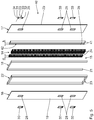
- the furniture element 7 has a plate-shaped base body 14, which is constructed in layers.
- the main body 14 has a so-called sandwich structure.
- the main body 14 comprises an inner structural layer 15, a first, in Fig. 2 Left side panel 16 shown on the left and a second, in Fig. 2 Right side cover plate 17 shown and a substantially peripheral end side cover 18.
- the first side cover plate 16 has an outwardly directed first side surface 19.
- the second side cover plate 17 has a second side surface 20 facing away from the first side surface 19 and arranged opposite one another.
- the side deck panels 16, 17 are made substantially identical.
- the side deck panels 16, 17 are in particular made of a medium-density fiberboard MDF.
- the side deck plates 16, 17 have, for example, a thickness of 2 mm to 6 mm.
- the end cover 18 includes two vertical end surface portions and a horizontal end surface portion connecting the two vertical end surface portions. It is also possible for a second horizontal end face section to be provided, which is arranged opposite the first, upper horizontal end face section on an underside of the front side cover 18. Such a lower, horizontal end face section, which in Fig. 2 and 3 not shown, forms a lower end of the front cover.
- the horizontal and vertical end face portions together form an end face 21 of the end face cover 18.
- the end face 21 faces outwards.
- the structural layer 15 comprises a substantially circumferential frame 22.
- the frame 22 is made according to the embodiment shown from high density wood fiber board material HDF with a density of at least 800 kg / m 3 . There are also other materials for the production of the frame 22 conceivable.
- the frame 22 is designed substantially rectangular and has a recess 23.
- the frame 22 is made of solid material in the form of a rotating bolt.
- the frame 22 is disposed outboard in the structural layer 15.
- the frame 22 forms a strength-increasing structural element.
- the structure layer 15 furthermore has a stiffening structural element in the form of a honeycomb structure 24.
- the honeycomb structure 24 is made of cardboard. Other materials such as paper, aluminum and / or plastic film for producing the honeycomb structure 24 are also conceivable.
- the honeycomb structure has a reduced weight and yet a high rigidity.
- the honeycomb structure 24 is lightweight construction. Due to the cavities in the honeycomb structure, this has insulating properties, in particular for thermal and acoustic insulation on. According to the embodiment shown, the honeycomb structure 24 is made in two parts with two honeycomb elements, which are spaced from one another.
- a plastic profile element 25 is provided as a cable channel.
- the cable channel 25 has a linear cable channel longitudinal axis 26. In a plane perpendicular to the cable channel longitudinal axis 26, the cable channel 25 has a rectangular cross section. There are also other cross-sectional shapes for the cable channel 25 conceivable. It is also conceivable that the two honeycomb structure elements of the honeycomb structure 24 are connected to one another, for example in an upper region facing the horizontal end face section.
- the cable channel has six first openings 27.
- the first openings 27 each serve as a feed opening for supplying a cable 12 of an electronic device 10 to the cable channel 25.
- the first openings 27 are each arranged in pairs on sidewalls 35 of the cable channel 25 aligned and opposite. That means the cable duct 25 according to the embodiment shown has three pairs of oppositely disposed first openings 27.
- the furniture element 7 is manufactured according to the board and frame technology.
- the side deck plates 16, 17 each have three side surface openings 28, via which the first openings 27 of the cable channel 25 are accessible.
- the side surface openings 28 in the side deck panels 16, 17 are rectangular. In particular, for manufacturing reasons, it is advantageous to execute the side surface openings 28 slot-shaped.
- the cable duct 25 also has a second opening 29.
- the second opening 29 is arranged on a lower end side of the cable channel 25.
- the second opening 29 is arranged in a plane perpendicular to the cable channel longitudinal axis 26.
- the first openings 27 are arranged in a plane parallel to the cable channel longitudinal axis 26 according to the embodiment shown.
- the cable channel 25 is fitted between the two elements of the honeycomb structure 24.
- the cable channel 25 is arranged with a lower end in the region of the second opening 29 in the recess 23 of the frame 22. This means that the second opening 29 is accessible via the recess 23 in the region of the end face 21 of the main body 14.
- the plastic profile element as a cable channel.
- the cable channel 25 as a cavity between the two elements of the honeycomb structure 24 on the one hand and between the two side deck plates 16, 17 on the other hand and the frame 22 formed.
- the openings provided in the side walls 35 of the cable channel 25 openings serve as second openings in the sense of the application, for example, if a power supply is integrated in a furniture system or a connection cable for data transmission from a first electronic device to a second electronic device to be performed.
- the cable channel 25 is glued to the honeycomb structure and / or the frame 22.
- each have a cap 30 is placed and locked in particular in the side surface opening 28 and / or the first opening 27.
- the first opening 27 is covered by the patch cap 30.
- the cap 30 has a cover frame 31.
- the cap 30 has a cover opening 32 open at the edge.
- the cap opening 32 is a cap pivot axis 33 about which a cap cover 34 of the cap 30 is pivotally attached to the cap frame 31.
- the cover cap pivot axis 33 is oriented horizontally. It is also conceivable that the cover cap pivot axis 33 is oriented vertically. Through the cover opening 32, the cable 12 can be guided when the cover cap 34 is closed.
- the standing element 4 is designed essentially analogously to the furniture element 7.
- the stand element openings 37, 38 correspond to the openings 27, 29, over which the passageway 36 is accessible.
- the passageway 36 is a cable channel.
- the wiring is supplied via the stand element opening 37 and discharged via the arranged on the opposite side stand element opening 38.
- the base body itself ie the side surfaces, the end face and the layer structure of the base body of the stand element 4, corresponds to that of the furniture element 7.
- the stand element 4 is a furniture element according to the invention.
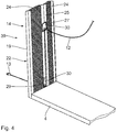
- Fig. 4 shows a further embodiment of a furniture element 39.
- Components that correspond to those described above with reference to the Fig. 1 to 3 have the same reference numbers and will not be discussed again in detail.
- the main difference is that in the furniture element 39, the second opening 29 is arranged on the first side surface 19 of the furniture element 39.
- the second opening 29 of the cable channel 25 is accessible via a side surface opening 28 in the first side cover plate 16 and covered by a cap 30.
- the first opening 27 is analogous to the first embodiment via a side surface opening 28 on the second side surface of the second side cover plate, which for purposes of illustration in the Fig. 4 not shown, arranged.
- the first opening 27 and the second opening 29 are arranged on opposite side surfaces of the main body 14.
- the first opening 27 and the second opening 29 are not aligned along a plate thickness direction.
- the cable channel 25 is vertically oriented in the furniture element 39. Along this vertical direction, the first opening 27 and the second opening 29 are arranged offset to one another.
- the furniture element 39 has a frame 22 and honeycomb structures 24 which surround the cable duct 25.
- the frame 22 is closed on a lower side surface, that is not executed with a recess. As a result, the stability and rigidity of the frame 22 is additionally increased.
- the furniture element 39 is preferably a side wall of a furniture system such as a shelving system or a room divider. It is also conceivable that the furniture element 39 represents a rear wall of a furniture system. In this case, a cable 12 inconspicuously to the rear, in particular to a room wall on which, for example, a socket for an electrical power supply is arranged, are performed.
- Fig. 4 illustrated embodiment of the furniture element 39 so it is not necessary that the cable 12 is guided by two adjacent furniture elements.
- the cable 12 is guided over a single furniture element 39 to the outside, ie out of the furniture system 1 out.
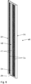
- Fig. 5 and 6 show a further embodiment of a furniture element 40.
- the cable channel 42 is formed by two stiffening elements 41 are arranged as a boundary on the honeycomb structures 24.
- the stiffening elements 41 are each designed as MDF strips having a width b, which corresponds to a thickness d of the honeycomb structures 24. This means that the stiffening elements 41 serve as additional stiffening of the structural layer.
- the stiffening elements can also be made of a different material.
- the remaining between the stiffening elements 41 space forms the cable channel 42.
- the cable channel 42 is particularly uncomplicated. In particular, the use of a complex shaped profile element is not required.
- the side surfaces 19, 20 facing surfaces of the cable channel 42 omitted.
- the cable channel 42 is open within the structural layer 15 to the side surfaces 19, 20.
- the frame 22 does not have the above arranged transverse element.
Landscapes
- Tables And Desks Characterized By Structural Shape (AREA)
- Details Of Indoor Wiring (AREA)
- Chair Legs, Seat Parts, And Backrests (AREA)
Priority Applications (2)
| Application Number | Priority Date | Filing Date | Title |
|---|---|---|---|
| SI201430035A SI2823732T1 (sl) | 2013-07-09 | 2014-07-07 | Pohištveni sistem s pohištvenim elementom |
| HRP20160675TT HRP20160675T1 (hr) | 2013-07-09 | 2016-06-14 | Namještajni sustav s elementom namještaja |
Applications Claiming Priority (1)
| Application Number | Priority Date | Filing Date | Title |
|---|---|---|---|
| DE102013213451.7A DE102013213451B4 (de) | 2013-07-09 | 2013-07-09 | Möbelelement für ein Möbelsystem sowie derartiges Möbelsystem |
Publications (2)
| Publication Number | Publication Date |
|---|---|
| EP2823732A1 EP2823732A1 (de) | 2015-01-14 |
| EP2823732B1 true EP2823732B1 (de) | 2016-04-13 |
Family
ID=51176141
Family Applications (1)
| Application Number | Title | Priority Date | Filing Date |
|---|---|---|---|
| EP14175922.5A Active EP2823732B1 (de) | 2013-07-09 | 2014-07-07 | Möbelsystem mit einem Möbelelement |
Country Status (7)
| Country | Link |
|---|---|
| EP (1) | EP2823732B1 (pl) |
| DE (1) | DE102013213451B4 (pl) |
| DK (1) | DK2823732T3 (pl) |
| ES (1) | ES2574610T3 (pl) |
| HR (1) | HRP20160675T1 (pl) |
| PL (1) | PL2823732T3 (pl) |
| SI (1) | SI2823732T1 (pl) |
Families Citing this family (2)
| Publication number | Priority date | Publication date | Assignee | Title |
|---|---|---|---|---|
| DE102020125759B4 (de) * | 2020-10-01 | 2024-03-21 | ambigence GmbH & Co. KG | Möbelkomponente |
| DE102024107520B4 (de) | 2024-03-15 | 2025-09-11 | Joachim Sonnberger | Campingmöbelleichtbauplatte für den Wohnmobil- oder Caravanausbau und Campingmöbelleichtbautür oder -klappe |
Family Cites Families (6)
| Publication number | Priority date | Publication date | Assignee | Title |
|---|---|---|---|---|
| DE3636743A1 (de) * | 1986-10-29 | 1987-03-19 | Alois E Schaub Fa | Moebelstueck zur aufnahme von komponenten eines tonwiedergabesystems, insbesondere einer hifi-anlage |
| SE526646C2 (sv) * | 2004-02-12 | 2005-10-18 | Thorsman Och Co Ab | Uttagsgolvbox med kabelutlopp |
| DE102005014276A1 (de) * | 2005-03-24 | 2006-10-05 | Fritz Egger Gmbh & Co. | Bauplatte, insbesondere Möbelplatte |
| DE102010000321A1 (de) * | 2010-02-05 | 2011-08-11 | Hettich-Heinze GmbH & Co. KG, 32139 | Verbindungsanordnung |
| DE102011108974A1 (de) * | 2011-07-28 | 2013-01-31 | Stephan Hagedorn | Funktionsplatte mit integrierten Anschlüssen, Kabelführungen und Bedienelementen, welche individuell gefertigt wird |
| DE202012100493U1 (de) * | 2012-02-14 | 2012-03-28 | SPECTRAL Audio Möbel GmbH | Möbel mit einem kastenförmigen Möbelkorpus und einer daran angebrachten Bildschirmhalterung |
-
2013
- 2013-07-09 DE DE102013213451.7A patent/DE102013213451B4/de not_active Expired - Fee Related
-
2014
- 2014-07-07 PL PL14175922.5T patent/PL2823732T3/pl unknown
- 2014-07-07 SI SI201430035A patent/SI2823732T1/sl unknown
- 2014-07-07 ES ES14175922.5T patent/ES2574610T3/es active Active
- 2014-07-07 EP EP14175922.5A patent/EP2823732B1/de active Active
- 2014-07-07 DK DK14175922.5T patent/DK2823732T3/en active
-
2016
- 2016-06-14 HR HRP20160675TT patent/HRP20160675T1/hr unknown
Also Published As
| Publication number | Publication date |
|---|---|
| SI2823732T1 (sl) | 2016-08-31 |
| DE102013213451B4 (de) | 2020-08-20 |
| PL2823732T3 (pl) | 2016-09-30 |
| EP2823732A1 (de) | 2015-01-14 |
| ES2574610T3 (es) | 2016-06-21 |
| HRP20160675T1 (hr) | 2016-07-15 |
| DE102013213451A1 (de) | 2015-01-15 |
| DK2823732T3 (en) | 2016-07-25 |
Similar Documents
| Publication | Publication Date | Title |
|---|---|---|
| EP0943265B1 (de) | Schranksystem | |
| EP3589165B1 (de) | Wand für einen möbelkorpus, verfahren zur herstellung einer solchen wand und möbelkorpus oder möbel mit einer solchen wand | |
| DE60220496T2 (de) | Schreibtisch und schreibtischsystem | |
| EP2823732B1 (de) | Möbelsystem mit einem Möbelelement | |
| CH706175A2 (de) | Regalpfosten. | |
| EP1891875B1 (de) | Bauplatte, insbesondere möbelplatte | |
| DE2321197A1 (de) | Vorrichtung zur verbindung von moebelstuecken | |
| DE102009011449B4 (de) | Möbel-oder Verkleidungsteil | |
| DE19959268A1 (de) | Energiesäule zur Aufnahme von elektrotechnischen Einrichtungen | |
| EP3378358B1 (de) | Möbelsystem | |
| DE102012216342B4 (de) | Arbeitsmöbel | |
| DE102012216340B4 (de) | Arbeitsmöbel | |
| DE9112637U1 (de) | Arbeitstisch | |
| DE3636743A1 (de) | Moebelstueck zur aufnahme von komponenten eines tonwiedergabesystems, insbesondere einer hifi-anlage | |
| DE102012216344B4 (de) | Arbeitsmöbel | |
| EP1142508A1 (de) | Arbeitsplatzsystem | |
| DE2911915A1 (de) | Turm zur halterung von hi-fi-geraeten und fernsehapparaten | |
| DE20301582U1 (de) | Präsentationsvorrichtung für elektronische Geräte | |
| DE202012103289U1 (de) | Möbel, insbesondere Tisch | |
| DE202021100766U1 (de) | Unterschrank-Bausatz, Sockelelement zur Verwendung in einem Unterschrank-Bausatz, und Satz von Sockelelementen | |
| DE3836997A1 (de) | Neuartiger schreibtisch-bausatz | |
| DE102010013768A1 (de) | Küchenmodul | |
| DE9105491U1 (de) | Aus einem Profilrohr bestehendes Stützbein | |
| DE8020557U1 (de) | Einbaumoebel fuer die geraete einer hifi-stereoanlage o.dgl. | |
| DE202018107268U1 (de) | Möbelsystem und ein das Möbelsystem enthaltendes Möbel |
Legal Events
| Date | Code | Title | Description |
|---|---|---|---|
| 17P | Request for examination filed |
Effective date: 20140707 |
|
| AK | Designated contracting states |
Kind code of ref document: A1 Designated state(s): AL AT BE BG CH CY CZ DE DK EE ES FI FR GB GR HR HU IE IS IT LI LT LU LV MC MK MT NL NO PL PT RO RS SE SI SK SM TR |
|
| AX | Request for extension of the european patent |
Extension state: BA ME |
|
| PUAI | Public reference made under article 153(3) epc to a published international application that has entered the european phase |
Free format text: ORIGINAL CODE: 0009012 |
|
| R17P | Request for examination filed (corrected) |
Effective date: 20150212 |
|
| RBV | Designated contracting states (corrected) |
Designated state(s): AL AT BE BG CH CY CZ DE DK EE ES FI FR GB GR HR HU IE IS IT LI LT LU LV MC MK MT NL NO PL PT RO RS SE SI SK SM TR |
|
| RIC1 | Information provided on ipc code assigned before grant |
Ipc: A47B 96/20 20060101AFI20150907BHEP Ipc: A47B 81/06 20060101ALN20150907BHEP |
|
| GRAP | Despatch of communication of intention to grant a patent |
Free format text: ORIGINAL CODE: EPIDOSNIGR1 |
|
| INTG | Intention to grant announced |
Effective date: 20151104 |
|
| RIC1 | Information provided on ipc code assigned before grant |
Ipc: A47B 81/06 20060101ALN20151023BHEP Ipc: A47B 96/20 20060101AFI20151023BHEP |
|
| GRAS | Grant fee paid |
Free format text: ORIGINAL CODE: EPIDOSNIGR3 |
|
| GRAA | (expected) grant |
Free format text: ORIGINAL CODE: 0009210 |
|
| AK | Designated contracting states |
Kind code of ref document: B1 Designated state(s): AL AT BE BG CH CY CZ DE DK EE ES FI FR GB GR HR HU IE IS IT LI LT LU LV MC MK MT NL NO PL PT RO RS SE SI SK SM TR |
|
| REG | Reference to a national code |
Ref country code: GB Ref legal event code: FG4D Free format text: NOT ENGLISH |
|
| REG | Reference to a national code |
Ref country code: AT Ref legal event code: REF Ref document number: 789121 Country of ref document: AT Kind code of ref document: T Effective date: 20160415 Ref country code: CH Ref legal event code: EP |
|
| REG | Reference to a national code |
Ref country code: IE Ref legal event code: FG4D Free format text: LANGUAGE OF EP DOCUMENT: GERMAN |
|
| REG | Reference to a national code |
Ref country code: DE Ref legal event code: R096 Ref document number: 502014000605 Country of ref document: DE |
|
| REG | Reference to a national code |
Ref country code: HR Ref legal event code: TUEP Ref document number: P20160675 Country of ref document: HR |
|
| REG | Reference to a national code |
Ref country code: ES Ref legal event code: FG2A Ref document number: 2574610 Country of ref document: ES Kind code of ref document: T3 Effective date: 20160621 |
|
| REG | Reference to a national code |
Ref country code: RO Ref legal event code: EPE |
|
| REG | Reference to a national code |
Ref country code: HR Ref legal event code: T1PR Ref document number: P20160675 Country of ref document: HR Ref country code: EE Ref legal event code: FG4A Ref document number: E011867 Country of ref document: EE Effective date: 20160516 |
|
| REG | Reference to a national code |
Ref country code: NL Ref legal event code: FP |
|
| REG | Reference to a national code |
Ref country code: FR Ref legal event code: PLFP Year of fee payment: 3 |
|
| REG | Reference to a national code |
Ref country code: DK Ref legal event code: T3 Effective date: 20160718 |
|
| REG | Reference to a national code |
Ref country code: SE Ref legal event code: TRGR |
|
| PG25 | Lapsed in a contracting state [announced via postgrant information from national office to epo] |
Ref country code: FI Free format text: LAPSE BECAUSE OF FAILURE TO SUBMIT A TRANSLATION OF THE DESCRIPTION OR TO PAY THE FEE WITHIN THE PRESCRIBED TIME-LIMIT Effective date: 20160413 Ref country code: NO Free format text: LAPSE BECAUSE OF FAILURE TO SUBMIT A TRANSLATION OF THE DESCRIPTION OR TO PAY THE FEE WITHIN THE PRESCRIBED TIME-LIMIT Effective date: 20160713 |
|
| REG | Reference to a national code |
Ref country code: SK Ref legal event code: T3 Ref document number: E 21284 Country of ref document: SK |
|
| PG25 | Lapsed in a contracting state [announced via postgrant information from national office to epo] |
Ref country code: PT Free format text: LAPSE BECAUSE OF FAILURE TO SUBMIT A TRANSLATION OF THE DESCRIPTION OR TO PAY THE FEE WITHIN THE PRESCRIBED TIME-LIMIT Effective date: 20160816 Ref country code: RS Free format text: LAPSE BECAUSE OF FAILURE TO SUBMIT A TRANSLATION OF THE DESCRIPTION OR TO PAY THE FEE WITHIN THE PRESCRIBED TIME-LIMIT Effective date: 20160413 |
|
| REG | Reference to a national code |
Ref country code: DE Ref legal event code: R097 Ref document number: 502014000605 Country of ref document: DE |
|
| PLBE | No opposition filed within time limit |
Free format text: ORIGINAL CODE: 0009261 |
|
| STAA | Information on the status of an ep patent application or granted ep patent |
Free format text: STATUS: NO OPPOSITION FILED WITHIN TIME LIMIT |
|
| PG25 | Lapsed in a contracting state [announced via postgrant information from national office to epo] |
Ref country code: SM Free format text: LAPSE BECAUSE OF FAILURE TO SUBMIT A TRANSLATION OF THE DESCRIPTION OR TO PAY THE FEE WITHIN THE PRESCRIBED TIME-LIMIT Effective date: 20160413 |
|
| 26N | No opposition filed |
Effective date: 20170116 |
|
| PG25 | Lapsed in a contracting state [announced via postgrant information from national office to epo] |
Ref country code: MC Free format text: LAPSE BECAUSE OF FAILURE TO SUBMIT A TRANSLATION OF THE DESCRIPTION OR TO PAY THE FEE WITHIN THE PRESCRIBED TIME-LIMIT Effective date: 20160413 |
|
| REG | Reference to a national code |
Ref country code: IE Ref legal event code: MM4A |
|
| REG | Reference to a national code |
Ref country code: HR Ref legal event code: ODRP Ref document number: P20160675 Country of ref document: HR Payment date: 20170629 Year of fee payment: 4 |
|
| REG | Reference to a national code |
Ref country code: FR Ref legal event code: PLFP Year of fee payment: 4 |
|
| PG25 | Lapsed in a contracting state [announced via postgrant information from national office to epo] |
Ref country code: IE Free format text: LAPSE BECAUSE OF NON-PAYMENT OF DUE FEES Effective date: 20160707 |
|
| PGFP | Annual fee paid to national office [announced via postgrant information from national office to epo] |
Ref country code: HR Payment date: 20170629 Year of fee payment: 4 Ref country code: CZ Payment date: 20170626 Year of fee payment: 4 Ref country code: RO Payment date: 20170628 Year of fee payment: 4 Ref country code: SK Payment date: 20170626 Year of fee payment: 4 |
|
| PGFP | Annual fee paid to national office [announced via postgrant information from national office to epo] |
Ref country code: LU Payment date: 20170720 Year of fee payment: 4 |
|
| PGFP | Annual fee paid to national office [announced via postgrant information from national office to epo] |
Ref country code: NL Payment date: 20170720 Year of fee payment: 4 |
|
| PGFP | Annual fee paid to national office [announced via postgrant information from national office to epo] |
Ref country code: ES Payment date: 20170818 Year of fee payment: 4 Ref country code: EE Payment date: 20170724 Year of fee payment: 4 |
|
| PGFP | Annual fee paid to national office [announced via postgrant information from national office to epo] |
Ref country code: SI Payment date: 20170623 Year of fee payment: 4 Ref country code: TR Payment date: 20170704 Year of fee payment: 4 Ref country code: DK Payment date: 20170724 Year of fee payment: 4 Ref country code: LV Payment date: 20170725 Year of fee payment: 4 Ref country code: BE Payment date: 20170720 Year of fee payment: 4 |
|
| PG25 | Lapsed in a contracting state [announced via postgrant information from national office to epo] |
Ref country code: HU Free format text: LAPSE BECAUSE OF FAILURE TO SUBMIT A TRANSLATION OF THE DESCRIPTION OR TO PAY THE FEE WITHIN THE PRESCRIBED TIME-LIMIT; INVALID AB INITIO Effective date: 20140707 |
|
| PG25 | Lapsed in a contracting state [announced via postgrant information from national office to epo] |
Ref country code: MT Free format text: LAPSE BECAUSE OF FAILURE TO SUBMIT A TRANSLATION OF THE DESCRIPTION OR TO PAY THE FEE WITHIN THE PRESCRIBED TIME-LIMIT Effective date: 20160413 Ref country code: GR Free format text: LAPSE BECAUSE OF FAILURE TO SUBMIT A TRANSLATION OF THE DESCRIPTION OR TO PAY THE FEE WITHIN THE PRESCRIBED TIME-LIMIT Effective date: 20160413 Ref country code: CY Free format text: LAPSE BECAUSE OF FAILURE TO SUBMIT A TRANSLATION OF THE DESCRIPTION OR TO PAY THE FEE WITHIN THE PRESCRIBED TIME-LIMIT Effective date: 20160413 Ref country code: MK Free format text: LAPSE BECAUSE OF FAILURE TO SUBMIT A TRANSLATION OF THE DESCRIPTION OR TO PAY THE FEE WITHIN THE PRESCRIBED TIME-LIMIT Effective date: 20160413 Ref country code: IS Free format text: LAPSE BECAUSE OF FAILURE TO SUBMIT A TRANSLATION OF THE DESCRIPTION OR TO PAY THE FEE WITHIN THE PRESCRIBED TIME-LIMIT Effective date: 20160413 |
|
| REG | Reference to a national code |
Ref country code: FR Ref legal event code: PLFP Year of fee payment: 5 |
|
| PG25 | Lapsed in a contracting state [announced via postgrant information from national office to epo] |
Ref country code: BG Free format text: LAPSE BECAUSE OF FAILURE TO SUBMIT A TRANSLATION OF THE DESCRIPTION OR TO PAY THE FEE WITHIN THE PRESCRIBED TIME-LIMIT Effective date: 20160413 |
|
| PGFP | Annual fee paid to national office [announced via postgrant information from national office to epo] |
Ref country code: LT Payment date: 20180628 Year of fee payment: 5 |
|
| PG25 | Lapsed in a contracting state [announced via postgrant information from national office to epo] |
Ref country code: AL Free format text: LAPSE BECAUSE OF FAILURE TO SUBMIT A TRANSLATION OF THE DESCRIPTION OR TO PAY THE FEE WITHIN THE PRESCRIBED TIME-LIMIT Effective date: 20160413 |
|
| PGFP | Annual fee paid to national office [announced via postgrant information from national office to epo] |
Ref country code: AT Payment date: 20180920 Year of fee payment: 11 |
|
| REG | Reference to a national code |
Ref country code: HR Ref legal event code: PBON Ref document number: P20160675 Country of ref document: HR Effective date: 20180707 |
|
| PG25 | Lapsed in a contracting state [announced via postgrant information from national office to epo] |
Ref country code: CZ Free format text: LAPSE BECAUSE OF NON-PAYMENT OF DUE FEES Effective date: 20180707 |
|
| REG | Reference to a national code |
Ref country code: EE Ref legal event code: MM4A Ref document number: E011867 Country of ref document: EE Effective date: 20180731 |
|
| REG | Reference to a national code |
Ref country code: DK Ref legal event code: EBP Effective date: 20180731 |
|
| REG | Reference to a national code |
Ref country code: NL Ref legal event code: MM Effective date: 20180801 |
|
| PG25 | Lapsed in a contracting state [announced via postgrant information from national office to epo] |
Ref country code: LU Free format text: LAPSE BECAUSE OF NON-PAYMENT OF DUE FEES Effective date: 20180707 |
|
| REG | Reference to a national code |
Ref country code: BE Ref legal event code: MM Effective date: 20180731 |
|
| REG | Reference to a national code |
Ref country code: SK Ref legal event code: MM4A Ref document number: E 21284 Country of ref document: SK Effective date: 20180707 |
|
| PG25 | Lapsed in a contracting state [announced via postgrant information from national office to epo] |
Ref country code: LV Free format text: LAPSE BECAUSE OF NON-PAYMENT OF DUE FEES Effective date: 20180707 Ref country code: HR Free format text: LAPSE BECAUSE OF NON-PAYMENT OF DUE FEES Effective date: 20180707 Ref country code: RO Free format text: LAPSE BECAUSE OF NON-PAYMENT OF DUE FEES Effective date: 20180707 Ref country code: EE Free format text: LAPSE BECAUSE OF NON-PAYMENT OF DUE FEES Effective date: 20180731 |
|
| REG | Reference to a national code |
Ref country code: SI Ref legal event code: KO00 Effective date: 20190305 |
|
| PG25 | Lapsed in a contracting state [announced via postgrant information from national office to epo] |
Ref country code: SI Free format text: LAPSE BECAUSE OF NON-PAYMENT OF DUE FEES Effective date: 20180708 Ref country code: NL Free format text: LAPSE BECAUSE OF NON-PAYMENT OF DUE FEES Effective date: 20180801 Ref country code: BE Free format text: LAPSE BECAUSE OF NON-PAYMENT OF DUE FEES Effective date: 20180731 Ref country code: SK Free format text: LAPSE BECAUSE OF NON-PAYMENT OF DUE FEES Effective date: 20180707 |
|
| PG25 | Lapsed in a contracting state [announced via postgrant information from national office to epo] |
Ref country code: DK Free format text: LAPSE BECAUSE OF NON-PAYMENT OF DUE FEES Effective date: 20180731 |
|
| REG | Reference to a national code |
Ref country code: ES Ref legal event code: FD2A Effective date: 20190917 |
|
| PG25 | Lapsed in a contracting state [announced via postgrant information from national office to epo] |
Ref country code: ES Free format text: LAPSE BECAUSE OF NON-PAYMENT OF DUE FEES Effective date: 20180708 |
|
| REG | Reference to a national code |
Ref country code: LT Ref legal event code: MM4D Effective date: 20190707 |
|
| GBPC | Gb: european patent ceased through non-payment of renewal fee |
Effective date: 20190707 |
|
| PG25 | Lapsed in a contracting state [announced via postgrant information from national office to epo] |
Ref country code: LT Free format text: LAPSE BECAUSE OF NON-PAYMENT OF DUE FEES Effective date: 20190707 Ref country code: GB Free format text: LAPSE BECAUSE OF NON-PAYMENT OF DUE FEES Effective date: 20190707 |
|
| PG25 | Lapsed in a contracting state [announced via postgrant information from national office to epo] |
Ref country code: TR Free format text: LAPSE BECAUSE OF NON-PAYMENT OF DUE FEES Effective date: 20190707 |
|
| PGFP | Annual fee paid to national office [announced via postgrant information from national office to epo] |
Ref country code: PL Payment date: 20230615 Year of fee payment: 10 |
|
| PGFP | Annual fee paid to national office [announced via postgrant information from national office to epo] |
Ref country code: IT Payment date: 20230731 Year of fee payment: 10 Ref country code: CH Payment date: 20230801 Year of fee payment: 10 |
|
| PGFP | Annual fee paid to national office [announced via postgrant information from national office to epo] |
Ref country code: SE Payment date: 20230724 Year of fee payment: 10 Ref country code: FR Payment date: 20230724 Year of fee payment: 10 |
|
| REG | Reference to a national code |
Ref country code: DE Ref legal event code: R081 Ref document number: 502014000605 Country of ref document: DE Owner name: MOLIS, MANFRED, DE Free format text: FORMER OWNER: MAJA-WERK MANFRED JAROSCH GMBH & CO. KG, 95359 KASENDORF, DE |
|
| PGFP | Annual fee paid to national office [announced via postgrant information from national office to epo] |
Ref country code: DE Payment date: 20240917 Year of fee payment: 11 |
|
| REG | Reference to a national code |
Ref country code: CH Ref legal event code: PL |
|
| REG | Reference to a national code |
Ref country code: SE Ref legal event code: EUG |
|
| REG | Reference to a national code |
Ref country code: AT Ref legal event code: MM01 Ref document number: 789121 Country of ref document: AT Kind code of ref document: T Effective date: 20240707 |
|
| PG25 | Lapsed in a contracting state [announced via postgrant information from national office to epo] |
Ref country code: AT Free format text: LAPSE BECAUSE OF NON-PAYMENT OF DUE FEES Effective date: 20240707 Ref country code: CH Free format text: LAPSE BECAUSE OF NON-PAYMENT OF DUE FEES Effective date: 20240731 |
|
| PG25 | Lapsed in a contracting state [announced via postgrant information from national office to epo] |
Ref country code: FR Free format text: LAPSE BECAUSE OF NON-PAYMENT OF DUE FEES Effective date: 20240731 |
|
| PG25 | Lapsed in a contracting state [announced via postgrant information from national office to epo] |
Ref country code: IT Free format text: LAPSE BECAUSE OF NON-PAYMENT OF DUE FEES Effective date: 20240707 |
|
| PG25 | Lapsed in a contracting state [announced via postgrant information from national office to epo] |
Ref country code: SE Free format text: LAPSE BECAUSE OF NON-PAYMENT OF DUE FEES Effective date: 20240708 |
|
| PG25 | Lapsed in a contracting state [announced via postgrant information from national office to epo] |
Ref country code: PL Free format text: LAPSE BECAUSE OF NON-PAYMENT OF DUE FEES Effective date: 20240707 |
|
| REG | Reference to a national code |
Ref country code: DE Ref legal event code: R119 Ref document number: 502014000605 Country of ref document: DE |
|
| PG25 | Lapsed in a contracting state [announced via postgrant information from national office to epo] |
Ref country code: DE Free format text: LAPSE BECAUSE OF NON-PAYMENT OF DUE FEES Effective date: 20260203 |