EP2821228A1 - Dichtung für Rakeleinrichtungen - Google Patents
Dichtung für Rakeleinrichtungen Download PDFInfo
- Publication number
- EP2821228A1 EP2821228A1 EP14170147.4A EP14170147A EP2821228A1 EP 2821228 A1 EP2821228 A1 EP 2821228A1 EP 14170147 A EP14170147 A EP 14170147A EP 2821228 A1 EP2821228 A1 EP 2821228A1
- Authority
- EP
- European Patent Office
- Prior art keywords
- seal
- doctor
- blade
- doctor blade
- Prior art date
- Legal status (The legal status is an assumption and is not a legal conclusion. Google has not performed a legal analysis and makes no representation as to the accuracy of the status listed.)
- Granted
Links
Images


Classifications
-
- B—PERFORMING OPERATIONS; TRANSPORTING
- B41—PRINTING; LINING MACHINES; TYPEWRITERS; STAMPS
- B41F—PRINTING MACHINES OR PRESSES
- B41F9/00—Rotary intaglio printing presses
- B41F9/06—Details
- B41F9/08—Wiping mechanisms
- B41F9/10—Doctors, scrapers, or like devices
- B41F9/1063—Seals between blades and cylinder
-
- B—PERFORMING OPERATIONS; TRANSPORTING
- B41—PRINTING; LINING MACHINES; TYPEWRITERS; STAMPS
- B41F—PRINTING MACHINES OR PRESSES
- B41F31/00—Inking arrangements or devices
- B41F31/02—Ducts, containers, supply or metering devices
- B41F31/027—Ink rail devices for inking ink rollers
Definitions
- the present invention relates to a seal for doctor devices of printing presses.
- Printing machines include anilox inking units and coating units with anilox rollers and cooperating squeegee devices, such as two doctor blade doctor blades (work doctor blade, closing squeegee) and doctor blade squeegees with only one doctor blade (work doctor blade).
- a doctor device has at its two ends in each case a rubber-elastic seal which rests against the anilox roller and the or each doctor blade.
- the contact area between the seal and the doctor blade is susceptible to leakage when the doctor blade moves relative to the seal. Such movements are carried out by the doctor blade, for example, when it is hired against the anilox roller and thereby bent.
- US20090193990A1 is a seal for a chambered doctor blade described.
- the seal has at each of its two ends a blade contact section.
- the seal abuts on the working doctor blade in the area of one blade contact section and on the closing blade in the area of the other blade contact section.
- the gasket in each blade contact portion with a pair of projecting blades which provide increased compliance or elasticity, thereby better following the movements of the doctor blade.
- the wings are arranged on the front, with which the blade contact section on the Doctor blade rests.
- the wings are susceptible to wear and their abrasion shortens the service life and re-occurrence of leakage.
- the invention has for its object to provide a respect to both leakage and wear less prone seal.
- the seal for metering devices of printing presses according to the invention has in its blade contact section a front side fitting against the doctor blade and a back side softer, more elastic or more flexible than the front side.
- the invention is based on the finding that it is not expedient to associate the increased resilience or elasticity of the blade contact section with its front side, and rather that the opposite is advantageous, namely to associate the increased resilience or elasticity of the blade contact section with the rear side.
- the dimensional stability of the front remains, which has a wear-reducing effect.
- the rear side forms a suspension, by which the seal is held in secure contact with the doctor blade in the area of its blade contact section, whereby leakage is prevented.
- the seal according to the invention is insensitive to alternating loads, which go along with the hiring and the shutdown of the doctor device to and from the anilox roller.
- squeegee boxes are turned on and off more frequently than chambered squeegees, since the squeegee boxes are better suited for this type of construction, because unlike chambered squeegees they do not have to be pumped out before they are parked.
- the seal according to the invention is particularly well suited for use in squeegee boxes.
- the invention also includes a squeegee device equipped with two seals according to the invention, in particular a squeegee box.
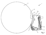
- FIG. 1 shows a detail of a printing machine 1 for the lithographic or planographic offset printing on sheet.
- the squeegee device 3 has a concave bottom 4, a pivotable rear wall 5, two side walls 6 and a single doctor blade 7, which is clamped to the bottom 4 and in the Printing operation is employed as a working doctor to the anilox roller 2 negative.
- the squeegee device 3 is not a chamber doctor blade, but a different squeegee box.
- the doctor device 3 has a storage chamber 8 (see FIG. 2 ) bounded by the bottom 4, by the rear wall 5 and at the lateral ends of the doctor device 3 by the side walls 6.
- the storage chamber 8 is open to the environment via its top refilling opening.
- the anilox roller 2 by means of the doctor device 3 to be supplied liquid - the color - stockpiled. This liquid supply is not shown in the drawing for reasons of clarity.
- the rear wall 5 is pivotable towards the doctor blade 5 to raise its level for the printing operation to a height above a voltage applied to the anilox roller 2 cutting edge of the doctor blade 7 by displacement of the liquid supply, and pivoted back from the doctor blade 7 in the position shown in the drawing, to the level for maintenance or set-up, the shutdown of the doctor device 3 of the Anilox roller 2 require - as color change - to lower to a height below the cutting edge.
- FIG. 2 shows that one of the side walls 6 on the operating side of the printing press 1 and the other side wall on the drive side.
- the two mutually parallel extending and perpendicular to the axis of rotation of the anilox roller 2 extending side walls 6 each carry a rubber-elastic seal 9 made of plastic, such as polyurethane, which is connected via an easily detachable connector with the respective side wall.
- the doctor blade 7 and the two seals 9 are each brought into contact with the anilox roller 2.
- the cutting edge of the doctor blade 7 and lips 10 see FIG. 4 ) of the seals 9 on the peripheral surface of the anilox roller 2, wherein the seals 9 rest in a lying between two end Schmitzringen 11 of the anilox roller 2 longitudinal section of the anilox roller 2 at this immediately adjacent to the bearer rings 11.
- the two seals 9 are identical parts, which is advantageous in terms of manufacturing technology, and each of them is compatible both with the drive-side side wall 6 and with the service-side side wall 6.
- FIG. 3 shows one of the seals 9 in a spatial representation.
- a use of the side wall 6 facing surface of the seal 9 extends in the longitudinal direction of the seal 9 convex and is provided with a likewise extending in this longitudinal direction plug-in groove 12 which extends almost over the entire length of the seal 9.
- the insertion groove 12 serves to attach the seal 9 on the side wall 6 and can also be referred to as a mounting groove.
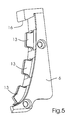
- the complementary projection or complementary projections (see FIG. 5 : Plug-in webs 13), which fit the plug-in groove 12 when fitting the seal 9 on the side wall 6, are very easy to clean after removing the seal 9 from the side wall 6 by means of a cleaning cloth, a brush or the like., Because the outer corner angle the projection or the projections, in contrast to the inner corner angles of a groove are very accessible.
- the upper end and the lower end of the seal 9 are contoured differently, the upper end is dull and the lower end has a wedge-shaped tip 14.
- the upper end forms a contact surface 15, with which the seal 9 in its correct seat on the side wall. 6 at a stop 16 (see FIGS. 1 and 5 ), which is arranged on the side wall 6 and blocks displacement of the seal 9 away from the doctor blade 7.
- the lower end forms a blade contact portion 20, in the region of the doctor blade 7 and the seal 9 abut each other.
- the blade contact portion 20 has a front side 17 and a back side 18, which converge in an edge 19 of the tip 14.
- the front 17 is on the same side of the seal 9 as the lips 10 (see FIG. 4 ).
- the rear side 18 is located on the same side of the seal 9 as the plug-in groove 12. With the insertion groove 12 is aligned between this and the edge 19, a first recess or first pocket 21 is inserted into that curved surface of the seal 9, in which also the plug-in 12th is introduced.
- the first pocket 21 is wider than the insertion groove 12 and deeper than a second recess or second pocket 22 (see FIG. 4 ), which is introduced between the lips 10 and the edge 19 in the seal 9.
- the web frame to the second Bag 22 is open in the area lying between the lips 10 and thus has a substantially U-shaped configuration.
- the coordinated dimensioning of the pockets 21, 22 ensures that the rear side 18 reacts softer, more resiliently or more elastically with the first pocket 21 when the knife contact section 20 or its front side 17 is pressed by the doctor blade 7 resting against it than the front side 17 which is more stable in terms of form
- substantially the back 18 and not the front 17 forms a suspension of the blade contact portion 20, by which suspension the blade contact portion 20 is held permanently in contact with the doctor blade 7 even during movements and deformations of the doctor blade 7, the is sufficiently tight or narrow to prevent liquid leakage in the area of the blade contact portion 20.
- FIG. 4 shows that the lips 10 form a V-shaped cross-section with two arms, each arm at its free end branches again into two V-shaped branches.
- FIG. 5 shows that the stop 16 has a wedge-shaped undercut, through which the seal 9 is secured against accidental detachment from the side wall 6.
- the plug-in webs 13 are arranged in alignment with each other in a row along the concave front side of the side wall 6.
- the width of the plug-in webs 13 is dimensioned so that with slight elastic expansion of the plug-in groove 12 (see FIG. 3 ) This can be slipped over the plug-in webs 13 tight. Due to the comparatively tight fit of the seal 9 on the plug-in webs 13, in addition to the wedge-shaped undercut of the stopper 16, the seal 9 is secured against slipping off the side wall 6.
- plug-in webs 13 could be replaced by a single plug-in web which extends continuously over the entire length of the row.
Landscapes
- Engineering & Computer Science (AREA)
- Mechanical Engineering (AREA)
- Inking, Control Or Cleaning Of Printing Machines (AREA)
Abstract
Description
- Vorliegende Erfindung betrifft eine Dichtung für Rakeleinrichtungen von Druckmaschinen.
- Druckmaschinen umfassen Anilox-Farbwerke und Lackierwerke mit Rasterwalzen und kooperierenden Rakeleinrichtungen, wie Kammerrakeln mit zwei Rakelmessern (Arbeitsrakel, Schließrakel) und Rakelfarbkästen mit nur einem Rakelmesser (Arbeitsrakel). Eine solche Rakeleinrichtung hat an ihren beiden Enden jeweils eine gummielastische Dichtung, welche an der Rasterwalze und dem oder jedem Rakelmesser anliegt.
- Der Kontaktbereich zwischen Dichtung und Rakelmesser ist bei Bewegungen des Rakelmessers relativ zur Dichtung anfällig für Leckage. Solche Bewegungen führt das Rakelmesser beispielsweise aus, wenn es an die Rasterwalze angestellt und dabei gebogen wird.
-
US20090193990A1 ist eine Dichtung für eine Kammerrakel beschrieben. Die Dichtung hat an ihren beiden Enden jeweils einen Messerkontaktabschnitt. Die Dichtung liegt im Bereich des einen Messerkontaktabschnitts an der Arbeitsrakel und im Bereich des anderen Messerkontaktabschnitts an der Schließrakel an. Zwischen den beiden Messerkontaktabschnitten befindet sich ein Walzenkontaktabschnitt, in dessen Bereich die Dichtung an der Rasterwalze anliegt. - Gemäß des o. g. Standes der Technik wird zur Lösung des Leckage-Problems vorgeschlagen, die Dichtung in jedem Messerkontaktabschnitt mit einem Paar vorspringender Flügel zu versehen, die eine erhöhte Nachgiebigkeit oder Elastizität bewirken und dadurch den Bewegungen des Rakelmessers besser folgen. Die Flügel sind auf der Vorderseite angeordnet, mit welcher der Messerkontaktabschnitt an dem Rakelmesser anliegt. Die Flügel sind aber verschleißanfällig und durch ihren Abrieb verkürzt sich die Standzeit und tritt wieder Leckage auf.
- Der Erfindung liegt die Aufgabe zugrunde, eine bezüglich sowohl Leckage als auch Verschleiß wenig anfällige Dichtung zu schaffen.
- Diese Aufgabe wird durch eine Dichtung mit den Merkmalen des Anspruchs 1 gelöst. Die erfindungsgemäße Dichtung für Rakeleinrichtungen von Druckmaschinen hat in ihrem Messerkontaktabschnitt eine an dem Rakelmesser anliegende Vorderseite und eine Rückseite, welche weicher, elastischer oder nachgiebiger als die Vorderseite ist.
- Der Erfindung liegt die Erkenntnis zugrunde, dass es nicht zweckmäßig ist, die erhöhte Nachgiebigkeit oder Elastizität des Messerkontaktabschnitts dessen Vorderseite zuzuordnen, und dass vielmehr das Gegenteil vorteilhaft ist, nämlich, die erhöhte Nachgiebigkeit oder Elastizität des Messerkontaktabschnitts der Rückseite zuzuordnen. Dadurch bleibt die Formstabilität der Vorderseite erhalten, was sich verschleißmindernd auswirkt. Die Rückseite bildet eine Federung, durch welche die Dichtung im Bereich ihres Messerkontaktabschnitts in sicherem Kontakt mit dem Rakelmesser gehalten wird, wodurch Leckage verhindert wird. Die in der Rakeleinrichtung bevorratete Flüssigkeit, z. B. Druckfarbe oder Drucklack, kann im Bereich des Messerkontaktabschnitts nicht zwischen der Dichtung und dem Rakelmesser hindurch aus der Rakeleinrichtung austreten.
- Die erfindungsgemäße Dichtung ist gegenüber Wechselbelastungen unempfindlich, die mit dem Anstellen und dem Abstellen der Rakeleinrichtung an die und von der Rasterwalze einhergehen. In der Praxis werden Rakelfarbkästen häufiger als Kammerrakeln an- und abgestellt, da die Rakelfarbkästen dafür bauartbedingt besser geeignet sind, weil sie im Gegensatz zu Kammerrakeln vor dem Abstellen nicht leergepumpt werden müssen. Vor diesem Hintergrund ist die erfindungsgemäße Dichtung besonders gut für ihren Einsatz in Rakelfarbkästen geeignet.
- Zur Erfindung gehört auch eine mit zwei erfindungsgemäßen Dichtungen ausgestattete Rakeleinrichtung, insbesondere ein Rakelfarbkasten.
- Konstruktiv und funktionell vorteilhafte Weiterbildungen der erfindungsgemäßen Dichtung sind in den Unteransprüchen genannt und ergeben sich aus der nachfolgenden Beschreibung eines Ausführungsbeispiels und der zugehörigen Zeichnung, in welcher zeigt:
- Fig. 1
- die Seitenansicht einer Rasterwalze und einer Rakeleinrichtung,
- Fig. 2
- die Draufsicht auf die Rasterwalze und die Rakeleinrichtung aus
Figur 1 , - Fig. 3
- eine Dichtung der Rakeleinrichtung aus den
Figuren 1 und2 , - Fig. 4
- die Dichtung aus
Fig. 3 in einer anderen Perspektive und - Fig. 5
- die Einzeldarstellung einer Seitenwand der Rakeleinrichtung aus den
Figuren 1 und2 . -
Figur 1 zeigt ausschnittsweise eine Druckmaschine 1 für den litho- oder planografischen Offsetdruck auf Bogen. In dem Ausschnitt dargestellt ist ein Anilox-Farbwerk mit einer Rasterwalze 2 und einer Rakeleinrichtung 3. Die Rakeleinrichtung 3 hat einen konkaven Boden 4, eine schwenkbare Rückwand 5, zwei Seitenwände 6 und ein einziges Rakelmesser 7, das an dem Boden 4 festgeklemmt ist und im Druckbetrieb als Arbeitsrakel an die Rasterwalze 2 negativ angestellt ist. Die Rakeleinrichtung 3 ist keine Kammerrakel, sondern ein davon verschiedener Rakelfarbkasten. Die Rakeleinrichtung 3 hat eine Vorratskammer 8 (sieheFigur 2 ), die von dem Boden 4, von der Rückwand 5 und an den lateralen Enden der Rakeleinrichtung 3 von den Seitenwänden 6 begrenzt wird. Die Vorratskammer 8 ist über ihre oberseitige Nachfüllöffnung zur Umgebung hin offen. In der Vorratskammer 8 wird die der Rasterwalze 2 mittels der Rakeleinrichtung 3 zuzuführende Flüssigkeit - die Farbe - bevorratet. Dieser Flüssigkeitsvorrat ist aus Gründen besserer Übersichtlichkeit zeichnerisch nicht mit dargestellt. - Die Rückwand 5 ist zum Rakelmesser 5 hin schwenkbar, um durch Verdrängung des Flüssigkeitsvorrats dessen Pegel für den Druckbetrieb auf eine Höhe oberhalb einer an der Rasterwalze 2 anliegende Schneide des Rakelmessers 7 anzuheben, und von dem Rakelmesser 7 weg in die zeichnerisch dargestellte Position zurück schwenkbar, um den Pegel für Wartungs- oder Rüstarbeiten, die ein Abstellen der Rakeleinrichtung 3 von der Rasterwalze 2 erfordern - wie Farbwechsel -, auf eine Höhe unterhalb der Schneide abzusenken.
-
Figur 2 zeigt, dass sich eine der Seitenwände 6 auf der Bedienungsseite der Druckmaschine 1 und die andere Seitenwand auf der Antriebsseite befindet. Die beiden sich miteinander parallel erstreckenden und relativ zur Rotationsachse der Rasterwalze 2 senkrecht erstreckenden Seitenwände 6 tragen jeweils eine gummielastische Dichtung 9 aus Kunststoff, wie Polyurethan, die über eine leicht lösbare Steckverbindung mit der jeweiligen Seitenwand verbunden ist. Beim Anstellen der gesamten Rakeleinrichtung 3 an die Rasterwalze 2 werden das Rakelmesser 7 und die beiden Dichtungen 9 jeweils in Kontakt mit der Rasterwalze 2 gebracht. Im Druckbetrieb liegen die Schneide des Rakelmessers 7 und Lippen 10 (sieheFigur 4 ) der Dichtungen 9 an der Umfangsfläche der Rasterwalze 2 an, wobei die Dichtungen 9 in einem zwischen zwei endseitigen Schmitzringen 11 der Rasterwalze 2 liegenden Längsabschnitt der Rasterwalze 2 an dieser unmittelbar neben den Schmitzringen 11 anliegen. - Die beiden Dichtungen 9 sind Gleichteile, was fertigungstechnisch vorteilhaft ist, und jede von ihnen ist sowohl mit der antriebsseitigen Seitenwand 6 als auch mit der bedienungsseitigen Seitenwand 6 kompatibel.
-
Figur 3 zeigt eine der Dichtungen 9 in räumlicher Darstellung. Eine verwendungsgemäß der Seitenwand 6 zugewandte Fläche der Dichtung 9 verläuft in Längsrichtung der Dichtung 9 konvex und ist mit einer ebenfalls in diese Längsrichtung verlaufenden Stecknut 12 versehen, die sich fast über die gesamt Länge der Dichtung 9 erstreckt. Die Stecknut 12 dient zum Aufstecken der Dichtung 9 auf die Seitenwand 6 und kann auch als Befestigungsnut bezeichnet werden. - Bekanntermaßen sind enge Vertiefungen, wie Nuten, schwer reinigbar, z. B., weil der Bediener mit dem Putzlappen in die Vertiefung kaum hineinkommt. Im Falle der Stecknut 12 ist dies aber kein Nachteil, weil eine gründliche Reinigung der Dichtung 9 gar nicht erforderlich ist, da die Dichtung 9 als ein Wegwerfteil konzipiert ist. Falls die Stecknut 12 durch in diese hineingelangte Druckfarbe verunreinigt ist, durch welche eine andere Druckfarbe des Folgeauftrags verschmutzt werden könnte, braucht keine aufwändige Reinigung der Dichtung 9 erfolgen und kann diese einfach durch eine saubere neue Dichtung ersetzt werden.
- Der komplementäre Vorsprung oder die komplementären Vorsprünge (siehe
Figur 5 : Steckstege 13), welche beim Aufstecken der Dichtung 9 auf die Seitenwand 6 in die Stecknut 12 passgenau eingreifen, sind nach dem Entfernen der Dichtung 9 von der Seitenwand 6 sehr einfach mittels eines Putzlappens, einer Bürste oder dergl. reinigbar, weil die außenliegenden Eckwinkel des Vorsprungs oder der Vorsprünge im Gegensatz zu den innenliegenden Eckwinkeln einer Nut sehr gut zugänglich sind. - Das obere Ende und das untere Ende der Dichtung 9 sind unterschiedlich konturiert, das obere Ende ist stumpf und das untere Ende hat eine keilförmige Spitze 14. Das obere Ende bildet eine Anlagefläche 15, mit welcher die Dichtung 9 bei ihrem korrekten Sitz auf der Seitenwand 6 an einem Anschlag 16 (siehe
Figuren 1 und5 ) anliegt, der an der Seitenwand 6 angeordnet ist und ein Verschieben der Dichtung 9 von dem Rakelmesser 7 weg blockiert. Das untere Ende bildet einen Messerkontaktabschnitt 20, in dessen Bereich das Rakelmesser 7 und die Dichtung 9 aneinander anliegen. - Der Messerkontaktabschnitt 20 hat eine Vorderseite 17 und eine Rückseite 18, die in einer Kante 19 der Spitze 14 zusammenlaufen. Die Vorderseite 17 befindet sich auf derselben Seite der Dichtung 9 wie die Lippen 10 (siehe
Figur 4 ). Die Rückseite 18 befindet sich auf derselben Seite der Dichtung 9 wie die Stecknut 12. Mit der Stecknut 12 fluchtend ist zwischen dieser und der Kante 19 eine erste Ausnehmung oder erste Tasche 21 in jene gekrümmte Fläche der Dichtung 9 eingebracht, in welche auch die Stecknut 12 eingebracht ist. Die erste Tasche 21 ist breiter als die Stecknut 12 und tiefer als eine zweite Ausnehmung oder zweite Tasche 22 (sieheFigur 4 ), die zwischen den Lippen 10 und der Kante 19 in die Dichtung 9 eingebracht ist. Um die erste Tasche 21 herum ist nur ein dünner Stegrahmen aus dem Kunststoff stehengeblieben und um die zweite Tasche 22 herum ist ebenfalls nur ein dünner Stegrahmen aus dem Material der Dichtung 9 stehengeblieben. Bestandteil des Stegrahmens um die erste Tasche 21 ist eine gemeinsame Trennwand der Stecknut 12 und der ersten Tasche 21. Der Stegrahmen um die zweite Tasche 22 ist im zwischen den Lippen 10 liegenden Bereich offen und hat somit eine im Wesentlichen U-förmige Gestalt. - Durch die aufeinander abgestimmte Dimensionierung der Taschen 21, 22 ist sichergestellt, dass die Rückseite 18 mit der ersten Tasche 21 bei Druck auf den Messerkontaktabschnitt 20 oder dessen Vorderseite 17 durch das daran anliegende Rakelmesser 7 weicher, nachgiebiger oder elastischer reagiert als die demgegenüber formstabilere Vorderseite 17 mit der zweiten Tasche 22. Somit bildet im Wesentlichen die Rückseite 18 und nicht die Vorderseite 17 eine Federung des Messerkontaktabschnitts 20, durch welche Federung der Messerkontaktabschnitt 20 auch bei Bewegungen und Verformungen des Rakelmessers 7 permanent in einem Kontakt mit dem Rakelmesser 7 gehalten wird, der hinreichend fest oder eng ist, um Flüssigkeitsleckage im Bereich des Messerkontaktabschnitts 20 zu verhindern.
-
Figur 4 zeigt, dass die Lippen 10 einen V-förmigen Querschnitt mit zwei Armen bilden, wobei jeder Arm an seinem freien Ende wiederum in zwei V-förmige Äste verzweigt. -
Figur 5 zeigt, dass der Anschlag 16 hat einen keilförmigen Hinterschnitt hat, durch welchen die Dichtung 9 gegen ein unbeabsichtigtes Ablösen von der Seitenwand 6 gesichert ist. Außerdem ist erkennbar, dass die Steckstege 13 miteinander fluchtend in einer Reihe entlang der konkaven Vorderseite der Seitenwand 6 angeordnet sind. Die Breite der Steckstege 13 ist so bemessen, dass unter geringfügiger elastischer Aufweitung der Stecknut 12 (sieheFigur 3 ) diese straff über die Steckstege 13 gestülpt werden kann. Durch den vergleichsweise straffen Sitz der Dichtung 9 auf den Steckstegen 13 ist zusätzlich zu dem keilförmigen Hinterschnitt des Anschlags 16 eine Sicherung der Dichtung 9 gegen ein Herunterrutschen von der Seitenwand 6 gegeben. - Bei einer zeichnerisch nicht dargestellten Modifikation könnte die Reihe von Steckstegen 13 durch einen einzigen Stecksteg ersetzt sein, der sich über die gesamte Länge der Reihe durchgehend erstreckt.
-
- 1
- Druckmaschine
- 2
- Rasterwalze
- 3
- Rakeleinrichtung
- 4
- Boden
- 5
- Rückwand
- 6
- Seitenwand
- 7
- Rakelmesser
- 8
- Vorratskammer
- 9
- Dichtung
- 10
- Lippe
- 11
- Schmitzring
- 12
- Stecknut
- 13
- Stecksteg
- 14
- Spitze
- 15
- Anlagefläche
- 16
- Anschlag
- 17
- Vorderseite
- 18
- Rückseite
- 19
- Kante
- 20
- Messerkontaktabschnitt
- 21
- erste Tasche
- 22
- zweite Tasche
Claims (10)
- Dichtung für Rakeleinrichtungen von Druckmaschinen, umfassend einen Messerkontaktabschnitt (20) mit einer an einem Rakelmesser (7) der Rakeleinrichtung (3) anliegenden Vorderseite (17) und einer Rückseite (18), welche weicher, elastischer oder nachgiebiger als die Vorderseite (17) ist.
- Dichtung nach Anspruch 1, wobei in die Rückseite (18) eine erste Tasche (21) eingebracht ist.
- Dichtung nach Anspruch 2, wobei in die Vorderseite (17) eine zweite Tasche (22) eingebracht ist.
- Dichtung nach Anspruch 3, wobei durch eine aufeinander abgestimmte Dimensionierung der ersten Tasche (21) und der zweiten Tasche (22) sichergestellt ist, dass die Rückseite (18) mit der ersten Tasche (21) bei Druck auf den Messerkontaktabschnitt (20) oder dessen Vorderseite (17) durch das daran anliegende Rakelmesser (7) nachgiebiger reagiert als die demgegenüber formstabilere Vorderseite (17) mit der zweiten Tasche (22).
- Dichtung nach Anspruch 4, wobei die erste Tasche (21) tiefer als die zweite Tasche (22) ist.
- Dichtung nach einem der Ansprüche 1 bis 5, wobei die Dichtung (9) eine Stecknut (12) zum Aufstecken der Dichtung (9) auf eine Seitenwand (6) der Rakeleinrichtung (3) aufweist.
- Dichtung nach Anspruch 2, wobei die Dichtung (9) eine Stecknut (12) zum Aufstecken der Dichtung (9) auf eine Seitenwand (6) der Rakeleinrichtung (3) aufweist und die erste Tasche (21) breiter als die Stecknut (12) ist.
- Dichtung nach Anspruch 1, wobei die Dichtung (9) ein oberes Ende und ein unteres Ende aufweist, die voneinander verschieden konturiert sind.
- Dichtung nach Anspruch 8, wobei das untere Ende den Messerkontaktabschnitt (20) bildet und das obere Ende eine Anlagefläche (15) für einen Anschlag (16) an einer Seitenwand (6) der Rakeleinrichtung (3) bildet.
- Rakeleinrichtung, umfassend zwei Seitenwände (6) mit jeweils einer darauf aufgesteckten Dichtung (9) nach einem der Ansprüche 1 bis 9.
Applications Claiming Priority (1)
| Application Number | Priority Date | Filing Date | Title |
|---|---|---|---|
| DE102013010751.2A DE102013010751A1 (de) | 2013-06-27 | 2013-06-27 | Dichtung für Rakeleinrichtungen |
Publications (2)
| Publication Number | Publication Date |
|---|---|
| EP2821228A1 true EP2821228A1 (de) | 2015-01-07 |
| EP2821228B1 EP2821228B1 (de) | 2016-02-03 |
Family
ID=50846813
Family Applications (1)
| Application Number | Title | Priority Date | Filing Date |
|---|---|---|---|
| EP14170147.4A Active EP2821228B1 (de) | 2013-06-27 | 2014-05-28 | Dichtung für Rakeleinrichtungen |
Country Status (5)
| Country | Link |
|---|---|
| US (1) | US9272503B2 (de) |
| EP (1) | EP2821228B1 (de) |
| JP (1) | JP3192962U (de) |
| CN (1) | CN104249554B (de) |
| DE (1) | DE102013010751A1 (de) |
Families Citing this family (3)
| Publication number | Priority date | Publication date | Assignee | Title |
|---|---|---|---|---|
| CN104494307A (zh) * | 2014-12-04 | 2015-04-08 | 广东东方精工科技股份有限公司 | 一种用于纸箱印刷机的刮刀端封结构 |
| DE202018101422U1 (de) * | 2018-03-14 | 2019-06-17 | Wigutec Gummitechnologie Gmbh & Co. Kg | Dichtungselement |
| EP4400315B1 (de) | 2023-01-10 | 2026-05-06 | Bobst Bielefeld GmbH | Dichtungssystem |
Citations (3)
| Publication number | Priority date | Publication date | Assignee | Title |
|---|---|---|---|---|
| EP0941846A1 (de) * | 1998-03-07 | 1999-09-15 | Fischer & Krecke Gmbh & Co. | Dichtung für Kammerrakel |
| EP0949074A1 (de) * | 1998-01-28 | 1999-10-13 | Fischer & Krecke Gmbh & Co. | Dichtung für Kammerrakel |
| US20090193990A1 (en) | 2008-02-06 | 2009-08-06 | Van Denend Mark E | Seal for an Ink Chamber with Improved Blade/Seal Area |
Family Cites Families (12)
| Publication number | Priority date | Publication date | Assignee | Title |
|---|---|---|---|---|
| DE4001733A1 (de) * | 1990-01-22 | 1991-07-25 | Windmoeller & Hoelscher | Rakelvorrichtung fuer ein spuelfarbwerk einer rotationsdruckmaschine |
| DE4138807C1 (en) * | 1991-11-26 | 1993-06-03 | Cornelis Wapenveld Nl Gorter | Colour chamber doctor - is for colour-transfer, screened circular cylindrical body such as screen roller or engraved cylinder |
| DE9215854U1 (de) | 1991-11-26 | 1993-03-25 | Gorter, Cornelis, Wapenveld | Einrichtung zum Beschichten laufender Materialbahnen, insbesondere Farbkammerrakel für einen farbübertragenden, gerasterten kreiszylindrischen Körper, wie eine Rasterwalze oder einen gravierten Zylinder |
| DE50201562D1 (de) * | 2002-02-08 | 2004-12-23 | Fischer & Krecke Gmbh & Co | Dichtung für Kammerrakel |
| SE527080C2 (sv) * | 2004-05-05 | 2005-12-20 | Akeboose Internat Ab | Anordning och förfarande för kammarrakel |
| CN101045368B (zh) * | 2006-03-28 | 2010-10-06 | 海德堡印刷机械股份公司 | 刮墨刀型墨斗 |
| US7597761B2 (en) * | 2006-08-10 | 2009-10-06 | Van Denend Mark E | Sealing assembly for an ink chamber which includes self-lubricating anilox roll seal with improved blade/seal area |
| DK176626B1 (da) * | 2007-08-21 | 2008-12-01 | Tresu Anlaeg As | Pakning til kammerrakel |
| CN100548680C (zh) * | 2008-01-16 | 2009-10-14 | 佛山市南海东方纸箱机械实业有限公司 | 纸箱印刷开槽机印刷单元单刮刀装置 |
| CN201394959Y (zh) * | 2009-01-22 | 2010-02-03 | 上宇科技有限公司 | 刮刀座 |
| DE202009013643U1 (de) * | 2009-10-26 | 2011-03-17 | Zeljko, Kitic | Dichtelement |
| DK201270014A (da) * | 2012-01-10 | 2013-07-11 | Tresu As | Pakning til kammerrakel |
-
2013
- 2013-06-27 DE DE102013010751.2A patent/DE102013010751A1/de not_active Withdrawn
-
2014
- 2014-05-28 EP EP14170147.4A patent/EP2821228B1/de active Active
- 2014-06-24 CN CN201410287461.1A patent/CN104249554B/zh active Active
- 2014-06-27 JP JP2014003379U patent/JP3192962U/ja not_active Expired - Lifetime
- 2014-06-27 US US14/317,165 patent/US9272503B2/en active Active
Patent Citations (3)
| Publication number | Priority date | Publication date | Assignee | Title |
|---|---|---|---|---|
| EP0949074A1 (de) * | 1998-01-28 | 1999-10-13 | Fischer & Krecke Gmbh & Co. | Dichtung für Kammerrakel |
| EP0941846A1 (de) * | 1998-03-07 | 1999-09-15 | Fischer & Krecke Gmbh & Co. | Dichtung für Kammerrakel |
| US20090193990A1 (en) | 2008-02-06 | 2009-08-06 | Van Denend Mark E | Seal for an Ink Chamber with Improved Blade/Seal Area |
Also Published As
| Publication number | Publication date |
|---|---|
| US20150001806A1 (en) | 2015-01-01 |
| EP2821228B1 (de) | 2016-02-03 |
| CN104249554A (zh) | 2014-12-31 |
| CN104249554B (zh) | 2018-12-07 |
| JP3192962U (ja) | 2014-09-11 |
| US9272503B2 (en) | 2016-03-01 |
| DE102013010751A1 (de) | 2014-12-31 |
Similar Documents
| Publication | Publication Date | Title |
|---|---|---|
| DE202009013643U1 (de) | Dichtelement | |
| DE60001419T2 (de) | Kammerrakelsystem | |
| EP2821228B1 (de) | Dichtung für Rakeleinrichtungen | |
| WO2003078077A1 (de) | Rakel-dosiersystem | |
| EP1342572B1 (de) | Dichtung für Kammerrakel | |
| EP1103377B1 (de) | Einrichtung zur Abdichtung einer Farbversorgung an Druckmaschinen | |
| EP1334830A1 (de) | Dichtung für Kammerrakel | |
| DE4447123C1 (de) | Kammerrakel für eine Rotationsdruckmaschine | |
| DE60029789T2 (de) | Dichtungsanordnung für eine Kammerrakel. | |
| DE102009039309B4 (de) | Vorrichtung mit Dichtstrang, Vorrakel und Schmierung als Enddichtung zwischen Druckzylinder und Farbwanne einer Rotationsdruckmaschine | |
| DE19536765C2 (de) | Farbgebersystem für eine Druckmaschine | |
| DE102007009881B4 (de) | Rakelfarbkasten | |
| EP1815983B1 (de) | Druckmaschine | |
| DE10302288B4 (de) | Dichtschild | |
| EP4401984B1 (de) | Kammerrakeldichtungsanordnung, rakelkammerdichtung und verfahren dafür | |
| WO2023151900A1 (de) | Endabdichtung | |
| EP2158085B1 (de) | Farbkammer für ein farbwerk einer rotationsdruckmaschine und verfahren zur herstellung einer solchen farbkammer | |
| DE202021102690U1 (de) | Dichtelement, Rakelkammer mit einem Dichtelement und Druckmaschine mit einem Dichtelement | |
| DE4213659A1 (de) | Rakelbalken | |
| DE19949346A1 (de) | Einrichtung zur Abdichtung eines farbführenden Reservoirs an Druckmaschinen | |
| DE20307718U1 (de) | Reinigungsvorrichtung für einen Zylinder einer Verarbeitungsmaschine | |
| DE102004031504B4 (de) | Farbkasten für eine Druckmaschine | |
| DE102013018792A1 (de) | Rakeleinrichtung einer Druckmaschine | |
| DE3421392A1 (de) | Dichtungsanordnung fuer eine walzen-dosiereinrichtung fuer fluessigkeiten | |
| DE102005040929B4 (de) | Farbkammerrakel |
Legal Events
| Date | Code | Title | Description |
|---|---|---|---|
| PUAI | Public reference made under article 153(3) epc to a published international application that has entered the european phase |
Free format text: ORIGINAL CODE: 0009012 |
|
| 17P | Request for examination filed |
Effective date: 20140528 |
|
| AK | Designated contracting states |
Kind code of ref document: A1 Designated state(s): AL AT BE BG CH CY CZ DE DK EE ES FI FR GB GR HR HU IE IS IT LI LT LU LV MC MK MT NL NO PL PT RO RS SE SI SK SM TR |
|
| AX | Request for extension of the european patent |
Extension state: BA ME |
|
| R17P | Request for examination filed (corrected) |
Effective date: 20150707 |
|
| RBV | Designated contracting states (corrected) |
Designated state(s): AL AT BE BG CH CY CZ DE DK EE ES FI FR GB GR HR HU IE IS IT LI LT LU LV MC MK MT NL NO PL PT RO RS SE SI SK SM TR |
|
| GRAP | Despatch of communication of intention to grant a patent |
Free format text: ORIGINAL CODE: EPIDOSNIGR1 |
|
| RIC1 | Information provided on ipc code assigned before grant |
Ipc: B41F 31/02 20060101AFI20150729BHEP |
|
| INTG | Intention to grant announced |
Effective date: 20150821 |
|
| GRAS | Grant fee paid |
Free format text: ORIGINAL CODE: EPIDOSNIGR3 |
|
| GRAA | (expected) grant |
Free format text: ORIGINAL CODE: 0009210 |
|
| AK | Designated contracting states |
Kind code of ref document: B1 Designated state(s): AL AT BE BG CH CY CZ DE DK EE ES FI FR GB GR HR HU IE IS IT LI LT LU LV MC MK MT NL NO PL PT RO RS SE SI SK SM TR |
|
| REG | Reference to a national code |
Ref country code: GB Ref legal event code: FG4D Free format text: NOT ENGLISH |
|
| REG | Reference to a national code |
Ref country code: AT Ref legal event code: REF Ref document number: 773470 Country of ref document: AT Kind code of ref document: T Effective date: 20160215 Ref country code: CH Ref legal event code: EP |
|
| REG | Reference to a national code |
Ref country code: IE Ref legal event code: FG4D Free format text: LANGUAGE OF EP DOCUMENT: GERMAN |
|
| REG | Reference to a national code |
Ref country code: DE Ref legal event code: R096 Ref document number: 502014000344 Country of ref document: DE |
|
| REG | Reference to a national code |
Ref country code: FR Ref legal event code: PLFP Year of fee payment: 3 |
|
| REG | Reference to a national code |
Ref country code: LT Ref legal event code: MG4D Ref country code: NL Ref legal event code: MP Effective date: 20160203 |
|
| PG25 | Lapsed in a contracting state [announced via postgrant information from national office to epo] |
Ref country code: HR Free format text: LAPSE BECAUSE OF FAILURE TO SUBMIT A TRANSLATION OF THE DESCRIPTION OR TO PAY THE FEE WITHIN THE PRESCRIBED TIME-LIMIT Effective date: 20160203 Ref country code: GR Free format text: LAPSE BECAUSE OF FAILURE TO SUBMIT A TRANSLATION OF THE DESCRIPTION OR TO PAY THE FEE WITHIN THE PRESCRIBED TIME-LIMIT Effective date: 20160504 Ref country code: ES Free format text: LAPSE BECAUSE OF FAILURE TO SUBMIT A TRANSLATION OF THE DESCRIPTION OR TO PAY THE FEE WITHIN THE PRESCRIBED TIME-LIMIT Effective date: 20160203 Ref country code: NO Free format text: LAPSE BECAUSE OF FAILURE TO SUBMIT A TRANSLATION OF THE DESCRIPTION OR TO PAY THE FEE WITHIN THE PRESCRIBED TIME-LIMIT Effective date: 20160503 Ref country code: FI Free format text: LAPSE BECAUSE OF FAILURE TO SUBMIT A TRANSLATION OF THE DESCRIPTION OR TO PAY THE FEE WITHIN THE PRESCRIBED TIME-LIMIT Effective date: 20160203 Ref country code: IT Free format text: LAPSE BECAUSE OF FAILURE TO SUBMIT A TRANSLATION OF THE DESCRIPTION OR TO PAY THE FEE WITHIN THE PRESCRIBED TIME-LIMIT Effective date: 20160203 |
|
| PG25 | Lapsed in a contracting state [announced via postgrant information from national office to epo] |
Ref country code: RS Free format text: LAPSE BECAUSE OF FAILURE TO SUBMIT A TRANSLATION OF THE DESCRIPTION OR TO PAY THE FEE WITHIN THE PRESCRIBED TIME-LIMIT Effective date: 20160203 Ref country code: SE Free format text: LAPSE BECAUSE OF FAILURE TO SUBMIT A TRANSLATION OF THE DESCRIPTION OR TO PAY THE FEE WITHIN THE PRESCRIBED TIME-LIMIT Effective date: 20160203 Ref country code: IS Free format text: LAPSE BECAUSE OF FAILURE TO SUBMIT A TRANSLATION OF THE DESCRIPTION OR TO PAY THE FEE WITHIN THE PRESCRIBED TIME-LIMIT Effective date: 20160603 Ref country code: PT Free format text: LAPSE BECAUSE OF FAILURE TO SUBMIT A TRANSLATION OF THE DESCRIPTION OR TO PAY THE FEE WITHIN THE PRESCRIBED TIME-LIMIT Effective date: 20160603 Ref country code: PL Free format text: LAPSE BECAUSE OF FAILURE TO SUBMIT A TRANSLATION OF THE DESCRIPTION OR TO PAY THE FEE WITHIN THE PRESCRIBED TIME-LIMIT Effective date: 20160203 Ref country code: LT Free format text: LAPSE BECAUSE OF FAILURE TO SUBMIT A TRANSLATION OF THE DESCRIPTION OR TO PAY THE FEE WITHIN THE PRESCRIBED TIME-LIMIT Effective date: 20160203 Ref country code: NL Free format text: LAPSE BECAUSE OF FAILURE TO SUBMIT A TRANSLATION OF THE DESCRIPTION OR TO PAY THE FEE WITHIN THE PRESCRIBED TIME-LIMIT Effective date: 20160203 Ref country code: BE Free format text: LAPSE BECAUSE OF NON-PAYMENT OF DUE FEES Effective date: 20160531 Ref country code: LV Free format text: LAPSE BECAUSE OF FAILURE TO SUBMIT A TRANSLATION OF THE DESCRIPTION OR TO PAY THE FEE WITHIN THE PRESCRIBED TIME-LIMIT Effective date: 20160203 |
|
| PG25 | Lapsed in a contracting state [announced via postgrant information from national office to epo] |
Ref country code: EE Free format text: LAPSE BECAUSE OF FAILURE TO SUBMIT A TRANSLATION OF THE DESCRIPTION OR TO PAY THE FEE WITHIN THE PRESCRIBED TIME-LIMIT Effective date: 20160203 Ref country code: DK Free format text: LAPSE BECAUSE OF FAILURE TO SUBMIT A TRANSLATION OF THE DESCRIPTION OR TO PAY THE FEE WITHIN THE PRESCRIBED TIME-LIMIT Effective date: 20160203 |
|
| REG | Reference to a national code |
Ref country code: DE Ref legal event code: R097 Ref document number: 502014000344 Country of ref document: DE |
|
| PG25 | Lapsed in a contracting state [announced via postgrant information from national office to epo] |
Ref country code: SM Free format text: LAPSE BECAUSE OF FAILURE TO SUBMIT A TRANSLATION OF THE DESCRIPTION OR TO PAY THE FEE WITHIN THE PRESCRIBED TIME-LIMIT Effective date: 20160203 Ref country code: RO Free format text: LAPSE BECAUSE OF FAILURE TO SUBMIT A TRANSLATION OF THE DESCRIPTION OR TO PAY THE FEE WITHIN THE PRESCRIBED TIME-LIMIT Effective date: 20160203 Ref country code: CZ Free format text: LAPSE BECAUSE OF FAILURE TO SUBMIT A TRANSLATION OF THE DESCRIPTION OR TO PAY THE FEE WITHIN THE PRESCRIBED TIME-LIMIT Effective date: 20160203 Ref country code: SK Free format text: LAPSE BECAUSE OF FAILURE TO SUBMIT A TRANSLATION OF THE DESCRIPTION OR TO PAY THE FEE WITHIN THE PRESCRIBED TIME-LIMIT Effective date: 20160203 |
|
| PLBE | No opposition filed within time limit |
Free format text: ORIGINAL CODE: 0009261 |
|
| STAA | Information on the status of an ep patent application or granted ep patent |
Free format text: STATUS: NO OPPOSITION FILED WITHIN TIME LIMIT |
|
| PG25 | Lapsed in a contracting state [announced via postgrant information from national office to epo] |
Ref country code: LU Free format text: LAPSE BECAUSE OF FAILURE TO SUBMIT A TRANSLATION OF THE DESCRIPTION OR TO PAY THE FEE WITHIN THE PRESCRIBED TIME-LIMIT Effective date: 20160528 |
|
| 26N | No opposition filed |
Effective date: 20161104 |
|
| REG | Reference to a national code |
Ref country code: IE Ref legal event code: MM4A |
|
| PG25 | Lapsed in a contracting state [announced via postgrant information from national office to epo] |
Ref country code: SI Free format text: LAPSE BECAUSE OF FAILURE TO SUBMIT A TRANSLATION OF THE DESCRIPTION OR TO PAY THE FEE WITHIN THE PRESCRIBED TIME-LIMIT Effective date: 20160203 Ref country code: BG Free format text: LAPSE BECAUSE OF FAILURE TO SUBMIT A TRANSLATION OF THE DESCRIPTION OR TO PAY THE FEE WITHIN THE PRESCRIBED TIME-LIMIT Effective date: 20160503 |
|
| REG | Reference to a national code |
Ref country code: FR Ref legal event code: PLFP Year of fee payment: 4 |
|
| PG25 | Lapsed in a contracting state [announced via postgrant information from national office to epo] |
Ref country code: IE Free format text: LAPSE BECAUSE OF NON-PAYMENT OF DUE FEES Effective date: 20160528 |
|
| PGFP | Annual fee paid to national office [announced via postgrant information from national office to epo] |
Ref country code: FR Payment date: 20170525 Year of fee payment: 4 |
|
| REG | Reference to a national code |
Ref country code: CH Ref legal event code: PL |
|
| PG25 | Lapsed in a contracting state [announced via postgrant information from national office to epo] |
Ref country code: LI Free format text: LAPSE BECAUSE OF NON-PAYMENT OF DUE FEES Effective date: 20170531 Ref country code: CH Free format text: LAPSE BECAUSE OF NON-PAYMENT OF DUE FEES Effective date: 20170531 |
|
| PG25 | Lapsed in a contracting state [announced via postgrant information from national office to epo] |
Ref country code: HU Free format text: LAPSE BECAUSE OF FAILURE TO SUBMIT A TRANSLATION OF THE DESCRIPTION OR TO PAY THE FEE WITHIN THE PRESCRIBED TIME-LIMIT; INVALID AB INITIO Effective date: 20140528 |
|
| PG25 | Lapsed in a contracting state [announced via postgrant information from national office to epo] |
Ref country code: MT Free format text: LAPSE BECAUSE OF FAILURE TO SUBMIT A TRANSLATION OF THE DESCRIPTION OR TO PAY THE FEE WITHIN THE PRESCRIBED TIME-LIMIT Effective date: 20160203 Ref country code: CY Free format text: LAPSE BECAUSE OF FAILURE TO SUBMIT A TRANSLATION OF THE DESCRIPTION OR TO PAY THE FEE WITHIN THE PRESCRIBED TIME-LIMIT Effective date: 20160203 Ref country code: MK Free format text: LAPSE BECAUSE OF FAILURE TO SUBMIT A TRANSLATION OF THE DESCRIPTION OR TO PAY THE FEE WITHIN THE PRESCRIBED TIME-LIMIT Effective date: 20160203 Ref country code: MC Free format text: LAPSE BECAUSE OF FAILURE TO SUBMIT A TRANSLATION OF THE DESCRIPTION OR TO PAY THE FEE WITHIN THE PRESCRIBED TIME-LIMIT Effective date: 20160203 |
|
| PG25 | Lapsed in a contracting state [announced via postgrant information from national office to epo] |
Ref country code: TR Free format text: LAPSE BECAUSE OF FAILURE TO SUBMIT A TRANSLATION OF THE DESCRIPTION OR TO PAY THE FEE WITHIN THE PRESCRIBED TIME-LIMIT Effective date: 20160203 Ref country code: AL Free format text: LAPSE BECAUSE OF FAILURE TO SUBMIT A TRANSLATION OF THE DESCRIPTION OR TO PAY THE FEE WITHIN THE PRESCRIBED TIME-LIMIT Effective date: 20160203 |
|
| GBPC | Gb: european patent ceased through non-payment of renewal fee |
Effective date: 20180528 |
|
| PG25 | Lapsed in a contracting state [announced via postgrant information from national office to epo] |
Ref country code: FR Free format text: LAPSE BECAUSE OF NON-PAYMENT OF DUE FEES Effective date: 20180531 Ref country code: GB Free format text: LAPSE BECAUSE OF NON-PAYMENT OF DUE FEES Effective date: 20180528 |
|
| REG | Reference to a national code |
Ref country code: AT Ref legal event code: MM01 Ref document number: 773470 Country of ref document: AT Kind code of ref document: T Effective date: 20190528 |
|
| PG25 | Lapsed in a contracting state [announced via postgrant information from national office to epo] |
Ref country code: AT Free format text: LAPSE BECAUSE OF NON-PAYMENT OF DUE FEES Effective date: 20190528 |
|
| REG | Reference to a national code |
Ref country code: DE Ref legal event code: R081 Ref document number: 502014000344 Country of ref document: DE Owner name: HEIDELBERGER DRUCKMASCHINEN INTELLECTUAL PROPE, DE Free format text: FORMER OWNER: HEIDELBERGER DRUCKMASCHINEN AG, 69115 HEIDELBERG, DE |
|
| P01 | Opt-out of the competence of the unified patent court (upc) registered |
Effective date: 20230427 |
|
| PGFP | Annual fee paid to national office [announced via postgrant information from national office to epo] |
Ref country code: DE Payment date: 20250531 Year of fee payment: 12 |