EP2821159B1 - Tool head for performing industrial operations having a wireless monitoring system - Google Patents
Tool head for performing industrial operations having a wireless monitoring system Download PDFInfo
- Publication number
- EP2821159B1 EP2821159B1 EP13174543.2A EP13174543A EP2821159B1 EP 2821159 B1 EP2821159 B1 EP 2821159B1 EP 13174543 A EP13174543 A EP 13174543A EP 2821159 B1 EP2821159 B1 EP 2821159B1
- Authority
- EP
- European Patent Office
- Prior art keywords
- robot
- tool head
- cylindrical body
- clinching
- head
- Prior art date
- Legal status (The legal status is an assumption and is not a legal conclusion. Google has not performed a legal analysis and makes no representation as to the accuracy of the status listed.)
- Active
Links
- 238000012544 monitoring process Methods 0.000 title description 3
- 210000000707 wrist Anatomy 0.000 claims description 13
- 238000012545 processing Methods 0.000 claims description 12
- 230000000284 resting effect Effects 0.000 claims description 11
- 230000005540 biological transmission Effects 0.000 claims description 9
- 238000004146 energy storage Methods 0.000 claims description 7
- 238000000034 method Methods 0.000 claims description 6
- 230000008569 process Effects 0.000 claims description 5
- 230000001276 controlling effect Effects 0.000 claims description 3
- 230000008878 coupling Effects 0.000 claims description 3
- 238000010168 coupling process Methods 0.000 claims description 3
- 238000005859 coupling reaction Methods 0.000 claims description 3
- 230000001939 inductive effect Effects 0.000 claims description 3
- 230000002596 correlated effect Effects 0.000 claims description 2
- 238000003466 welding Methods 0.000 description 12
- 239000002184 metal Substances 0.000 description 6
- 238000004519 manufacturing process Methods 0.000 description 4
- 230000000903 blocking effect Effects 0.000 description 2
- 230000006835 compression Effects 0.000 description 2
- 238000007906 compression Methods 0.000 description 2
- 238000009429 electrical wiring Methods 0.000 description 2
- 230000008030 elimination Effects 0.000 description 2
- 238000003379 elimination reaction Methods 0.000 description 2
- 230000008859 change Effects 0.000 description 1
- 238000006243 chemical reaction Methods 0.000 description 1
- 238000004891 communication Methods 0.000 description 1
- 238000010276 construction Methods 0.000 description 1
- 230000000875 corresponding effect Effects 0.000 description 1
- 238000010586 diagram Methods 0.000 description 1
- 230000004907 flux Effects 0.000 description 1
- 230000006872 improvement Effects 0.000 description 1
- 238000003754 machining Methods 0.000 description 1
- 238000012423 maintenance Methods 0.000 description 1
- 230000004048 modification Effects 0.000 description 1
- 238000012986 modification Methods 0.000 description 1
- 230000003287 optical effect Effects 0.000 description 1
- 230000009467 reduction Effects 0.000 description 1
- 230000001105 regulatory effect Effects 0.000 description 1
- 238000005096 rolling process Methods 0.000 description 1
Images


Classifications
-
- B—PERFORMING OPERATIONS; TRANSPORTING
- B21—MECHANICAL METAL-WORKING WITHOUT ESSENTIALLY REMOVING MATERIAL; PUNCHING METAL
- B21D—WORKING OR PROCESSING OF SHEET METAL OR METAL TUBES, RODS OR PROFILES WITHOUT ESSENTIALLY REMOVING MATERIAL; PUNCHING METAL
- B21D39/00—Application of procedures in order to connect objects or parts, e.g. coating with sheet metal otherwise than by plating; Tube expanders
- B21D39/02—Application of procedures in order to connect objects or parts, e.g. coating with sheet metal otherwise than by plating; Tube expanders of sheet metal by folding, e.g. connecting edges of a sheet to form a cylinder
- B21D39/021—Application of procedures in order to connect objects or parts, e.g. coating with sheet metal otherwise than by plating; Tube expanders of sheet metal by folding, e.g. connecting edges of a sheet to form a cylinder for panels, e.g. vehicle doors
- B21D39/023—Application of procedures in order to connect objects or parts, e.g. coating with sheet metal otherwise than by plating; Tube expanders of sheet metal by folding, e.g. connecting edges of a sheet to form a cylinder for panels, e.g. vehicle doors using rollers
-
- B—PERFORMING OPERATIONS; TRANSPORTING
- B23—MACHINE TOOLS; METAL-WORKING NOT OTHERWISE PROVIDED FOR
- B23Q—DETAILS, COMPONENTS, OR ACCESSORIES FOR MACHINE TOOLS, e.g. ARRANGEMENTS FOR COPYING OR CONTROLLING; MACHINE TOOLS IN GENERAL CHARACTERISED BY THE CONSTRUCTION OF PARTICULAR DETAILS OR COMPONENTS; COMBINATIONS OR ASSOCIATIONS OF METAL-WORKING MACHINES, NOT DIRECTED TO A PARTICULAR RESULT
- B23Q15/00—Automatic control or regulation of feed movement, cutting velocity or position of tool or work
- B23Q15/007—Automatic control or regulation of feed movement, cutting velocity or position of tool or work while the tool acts upon the workpiece
- B23Q15/12—Adaptive control, i.e. adjusting itself to have a performance which is optimum according to a preassigned criterion
-
- B—PERFORMING OPERATIONS; TRANSPORTING
- B21—MECHANICAL METAL-WORKING WITHOUT ESSENTIALLY REMOVING MATERIAL; PUNCHING METAL
- B21D—WORKING OR PROCESSING OF SHEET METAL OR METAL TUBES, RODS OR PROFILES WITHOUT ESSENTIALLY REMOVING MATERIAL; PUNCHING METAL
- B21D37/00—Tools as parts of machines covered by this subclass
-
- B—PERFORMING OPERATIONS; TRANSPORTING
- B23—MACHINE TOOLS; METAL-WORKING NOT OTHERWISE PROVIDED FOR
- B23K—SOLDERING OR UNSOLDERING; WELDING; CLADDING OR PLATING BY SOLDERING OR WELDING; CUTTING BY APPLYING HEAT LOCALLY, e.g. FLAME CUTTING; WORKING BY LASER BEAM
- B23K37/00—Auxiliary devices or processes, not specially adapted to a procedure covered by only one of the preceding main groups
- B23K37/02—Carriages for supporting the welding or cutting element
- B23K37/0258—Electric supply or control circuits therefor
-
- B—PERFORMING OPERATIONS; TRANSPORTING
- B23—MACHINE TOOLS; METAL-WORKING NOT OTHERWISE PROVIDED FOR
- B23P—METAL-WORKING NOT OTHERWISE PROVIDED FOR; COMBINED OPERATIONS; UNIVERSAL MACHINE TOOLS
- B23P19/00—Machines for simply fitting together or separating metal parts or objects, or metal and non-metal parts, whether or not involving some deformation; Tools or devices therefor so far as not provided for in other classes
- B23P19/04—Machines for simply fitting together or separating metal parts or objects, or metal and non-metal parts, whether or not involving some deformation; Tools or devices therefor so far as not provided for in other classes for assembling or disassembling parts
-
- B—PERFORMING OPERATIONS; TRANSPORTING
- B25—HAND TOOLS; PORTABLE POWER-DRIVEN TOOLS; MANIPULATORS
- B25J—MANIPULATORS; CHAMBERS PROVIDED WITH MANIPULATION DEVICES
- B25J11/00—Manipulators not otherwise provided for
-
- B—PERFORMING OPERATIONS; TRANSPORTING
- B25—HAND TOOLS; PORTABLE POWER-DRIVEN TOOLS; MANIPULATORS
- B25J—MANIPULATORS; CHAMBERS PROVIDED WITH MANIPULATION DEVICES
- B25J11/00—Manipulators not otherwise provided for
- B25J11/005—Manipulators for mechanical processing tasks
-
- B—PERFORMING OPERATIONS; TRANSPORTING
- B25—HAND TOOLS; PORTABLE POWER-DRIVEN TOOLS; MANIPULATORS
- B25J—MANIPULATORS; CHAMBERS PROVIDED WITH MANIPULATION DEVICES
- B25J13/00—Controls for manipulators
- B25J13/006—Controls for manipulators by means of a wireless system for controlling one or several manipulators
-
- B—PERFORMING OPERATIONS; TRANSPORTING
- B25—HAND TOOLS; PORTABLE POWER-DRIVEN TOOLS; MANIPULATORS
- B25J—MANIPULATORS; CHAMBERS PROVIDED WITH MANIPULATION DEVICES
- B25J13/00—Controls for manipulators
- B25J13/08—Controls for manipulators by means of sensing devices, e.g. viewing or touching devices
- B25J13/085—Force or torque sensors
-
- B—PERFORMING OPERATIONS; TRANSPORTING
- B25—HAND TOOLS; PORTABLE POWER-DRIVEN TOOLS; MANIPULATORS
- B25J—MANIPULATORS; CHAMBERS PROVIDED WITH MANIPULATION DEVICES
- B25J15/00—Gripping heads and other end effectors
- B25J15/0019—End effectors other than grippers
-
- B—PERFORMING OPERATIONS; TRANSPORTING
- B25—HAND TOOLS; PORTABLE POWER-DRIVEN TOOLS; MANIPULATORS
- B25J—MANIPULATORS; CHAMBERS PROVIDED WITH MANIPULATION DEVICES
- B25J19/00—Accessories fitted to manipulators, e.g. for monitoring, for viewing; Safety devices combined with or specially adapted for use in connection with manipulators
- B25J19/0025—Means for supplying energy to the end effector
- B25J19/0045—Contactless power transmission, e.g. by magnetic induction
-
- G—PHYSICS
- G05—CONTROLLING; REGULATING
- G05B—CONTROL OR REGULATING SYSTEMS IN GENERAL; FUNCTIONAL ELEMENTS OF SUCH SYSTEMS; MONITORING OR TESTING ARRANGEMENTS FOR SUCH SYSTEMS OR ELEMENTS
- G05B19/00—Programme-control systems
- G05B19/02—Programme-control systems electric
- G05B19/18—Numerical control [NC], i.e. automatically operating machines, in particular machine tools, e.g. in a manufacturing environment, so as to execute positioning, movement or co-ordinated operations by means of programme data in numerical form
-
- H—ELECTRICITY
- H04—ELECTRIC COMMUNICATION TECHNIQUE
- H04B—TRANSMISSION
- H04B1/00—Details of transmission systems, not covered by a single one of groups H04B3/00 - H04B13/00; Details of transmission systems not characterised by the medium used for transmission
- H04B1/38—Transceivers, i.e. devices in which transmitter and receiver form a structural unit and in which at least one part is used for functions of transmitting and receiving
-
- B—PERFORMING OPERATIONS; TRANSPORTING
- B23—MACHINE TOOLS; METAL-WORKING NOT OTHERWISE PROVIDED FOR
- B23Q—DETAILS, COMPONENTS, OR ACCESSORIES FOR MACHINE TOOLS, e.g. ARRANGEMENTS FOR COPYING OR CONTROLLING; MACHINE TOOLS IN GENERAL CHARACTERISED BY THE CONSTRUCTION OF PARTICULAR DETAILS OR COMPONENTS; COMBINATIONS OR ASSOCIATIONS OF METAL-WORKING MACHINES, NOT DIRECTED TO A PARTICULAR RESULT
- B23Q3/00—Devices holding, supporting, or positioning work or tools, of a kind normally removable from the machine
-
- G—PHYSICS
- G05—CONTROLLING; REGULATING
- G05B—CONTROL OR REGULATING SYSTEMS IN GENERAL; FUNCTIONAL ELEMENTS OF SUCH SYSTEMS; MONITORING OR TESTING ARRANGEMENTS FOR SUCH SYSTEMS OR ELEMENTS
- G05B2219/00—Program-control systems
- G05B2219/30—Nc systems
- G05B2219/33—Director till display
- G05B2219/33192—Radio link, wireless
Definitions
- the present invention relates to systems for performing industrial operations, of the type comprising:
- tool head is understood to indicate a tool head designed for performing any industrial operation, such as for example a clinching operation or a welding operation, for example electrical spot welding or laser welding, or even only an operation of movement of a piece with the aid of a gripping tool.
- tool is understood to indicate any tool or apparatus used on the tool head, such as for example a clinching roller or a pair of electrodes for electrical welding, or an optical device for focusing a laser beam, or a gripping tool.
- the invention is in general applicable to any system that envisages the use of a tool head for performing industrial operations.
- the invention regards systems in which the tool head is carried by a robot, in particular a multi-axis industrial robot of the type including a base structure, an articulated robot wrist, to which the tool head is removably connected, and a chain of mutually articulated robot elements that connect the base structure of the robot to the robot wrist.
- the tool head carried by the robot is a clinching head, provided with one or more clinching rollers pre-arranged for engaging and rolling along the extension of an edge of a metal sheet to be bent (for example, along the perimeter of a motor-vehicle door structure on a line for the production of motor-vehicle doors).
- associated to the clinching head are one or more force sensors that detect the load on the clinching rollers during execution of the clinching operation.
- the present invention is in any case of general application and can be envisaged also in the case of a tool head manoeuvred manually by an operator, such as for example a manually controlled electrical-spot-welding head.
- a system according to the preamble of claim 1 is known from US 2012/0247208 A1 .
- robots are used to perform a quality check on pieces obtained at the end of an industrial line.
- the subject of the present invention is a system as set forth in claim 1.
- the system according to the invention enables provision on the tool head of a data-acquisition and transmission module of very small dimensions, capable of handling a large amount of data and, notwithstanding this, capable of operating substantially continuously for long periods of time.
- control module mounted on the tool head also comprises a device for storing electrical energy that provides autonomously for electrical supply of all the devices on board the tool head.
- Elimination of the wiring consequently enables a drastic reduction of the need for stoppages for maintenance purposes, with consequent increase in productivity.
- Elimination of the wiring in many applications, likewise enables provision of the tool head as a unit that is completely autonomous with respect to the structure that supports it (for example, a robot), with consequent possibility of rapid replacement of the tool head, for example when it is necessary to change the type of machining operation.
- the system according to the invention can in any case enable easy and rapid wireless charging of the energy-storage device.
- the system according to the invention is substantially different and represents a substantial improvement, as compared to the known systems, in which wireless communication is used simply for exchanging signals between the sensors on board the tool head and the stationary control unit.
- the sensors provided on board the tool head may be of any number and of any nature (whether analog or digital).
- the system according to the invention is in particular able to provide simultaneously for supply and monitoring of a plurality of sensors dedicated to detecting a plurality of different operating parameters of the tool head.
- an electronic processing unit designed to process data coming from the above wireless receiving unit and from the above control unit.
- the control unit, the stationary wireless receiving unit, and the processing unit may be associated to or integrated with one another.
- the second charging means and/or the data-receiving unit may be stationary. It is also possible to envisage second stationary charging means associated to and/or integrated in a stationary wireless receiving unit.
- the workstation with the second charging means and/or the data-receiving unit may be on board the robot, in a part of the robot along the chain of elements that connects the base of the robot to the wrist of the robot in such a way that the robot itself is able to carry the tool head into the vicinity of the part of the robot on which the second charging means and/or the data-receiving unit are provided.
- Figure 1 of the annexed drawings shows, purely by way of example, application of the invention to a clinching station provided along a line for the production of motor-vehicle doors, for performing the operation of clinching of the two sheet-metal panels that constitute the structure of the door along the perimeter of the door.
- the door structure D is laid in a horizontal position above a cradle C carried by a base B.
- the door structure D is pressed on the cradle C by a pressure member P carried at the bottom end of a vertically mobile column P1.
- the clinching operation is performed by means of a clinching head H, which is removably mounted on the wrist W of a multi-axis articulated robot R of any known type, comprising a base structure R1 and a plurality of mutually articulated robot elements that connect the base structure R1 to the robot wrist W.
- Operation of the robot is controlled, in a way in itself known, by means of a stationary controller M of any type in itself known. Consequently, in this specific application, the control unit M of the tool head is the control unit of the robot.
- the control unit of the tool head may be any control unit associated to the workstation in which the tool head operates.
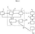
- the system comprises at least one sensor S associated to the tool head H and configured for detecting an operating parameter of the tool head.
- the sensor S is connected to a control module E mounted on the tool head and including a data-acquisition unit A, connected to the sensor S and configured for acquiring the data coming from the sensor S.
- the control module E further comprises a wireless-transmission unit T connected to the acquisition unit A for receiving the data acquired by the sensor and configured for transmitting, in wireless modem, the aforesaid acquired data to a wireless receiving unit U.
- the data-acquisition unit A may be pre-arranged for carrying out, not only mere acquisition of data, but also an initial processing or treatment of the data prior to their transmission (for example, an analog-to-digital conversion of the signal).
- both the wireless receiving unit U and the control unit M of the robot are connected to an electronic processing unit F that is consequently able to receive from the unit U the data coming from the sensors S and from the unit M the data regarding the operating parameters of the robot, during the operating cycle of the robot (see also Figure 1 ).
- control unit M the stationary wireless receiving unit U, and the processing unit F
- processing unit F the processing unit
- the control module E mounted on board the tool head further comprises a device for storing electrical energy EA, for electrical supply of the sensor S, of the data-acquisition unit A, and of the wireless transmission unit T.
- Figure 2 is a schematic representation of a direct connection between the device EA and the sensor S.
- the device EA may be pre-arranged for supplying the sensor S both via a direct connection and via the data-acquisition unit A, as well as via interposition of a supply-regulator device of any known type. The same applies of course for electrical supply of all the other devices included in the control module E.
- any wireless transmission protocol suited to guaranteeing transmissions in an industrial environment may be used, such as for example the Bluetooth protocol or the Zig-Bee protocol, or the Wi-Fi protocol, or any of the protocols derived therefrom.
- the system comprises wireless charging means CH for charging the device for storing electrical energy EA, which comprise first charging means CH1 carried by the tool head and connected to the energy-storage device EA and second charging means CH2 provided in a position remote from the tool head, for example in a stationary position above a column 1 (as in the example illustrated in Figure 1 ).
- the wireless charging means CH1, CH2 are designed to operate when they are in a position where they are set close up, in any known way, for example by means of an inductive charging system, i.e., providing in the charging means CH1 a turn that concatenates the magnetic flux produced by another turn contained in the charging means CH2.
- the second charging means CH2 may also be associated to and/or integrated, for example, in the wireless receiving unit U.
- the workstation with the second charging means CH2 may be located on board the robot, in a part of the robot along the chain of elements that connects the base of the robot to the wrist of the robot, in such a way that the robot itself is able to carry the tool head into the vicinity of the part of the robot on which the second charging means are provided.
- the system according to the invention not only is wireless transmission of the data coming from the sensors associated to the tool head envisaged, but also wireless charging means that enable charging of the energy-storage device EA, which is to supply both the unit of the control module E, located on board the tool head, and also the sensors S associated to the tool head.
- the processing unit F may use and process the data received from the unit U, indicating the parameters detected by the sensors S, associating them to the information received from the robot control unit M, regarding the operating cycle of the robot, so as to obtain precise and immediate information on the functional parameters of the system, during execution of the industrial operation, in modalities correlated to the position of the robot.
- the processing unit F will consequently be able to evaluate and associate the corresponding operating parameters to each operating position of the robot.
- the clinching head H provided with the control module E, which is represented schematically in Figure 2 .
- the module E is connected to a box 2 containing the electrical connectors for connection of the cables 3 (see Figure 5 ) that come under the two sensors, which, in the case of the example illustrated, are associated to the clinching head.
- the above tool head may in general be of any known type.
- a clinching head that may be used is the one that has formed the subject of the international patent application No. WO 2012/160512 filed in the name of the present applicant.
- the clinching head presents the further innovative characteristics that will be described hereinafter.
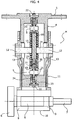
- a clinching head H comprises an inner cylindrical body 4 provided at the top with a disk-shaped flange 5, which can be screwed to the wrist of the robot R.
- the clinching head H carries two clinching rollers 6, 7, of different diameter, which can be used selectively during clinching operations, according to the need.
- the two rollers 6, 7 are carried by one and the same shaft 8, which is rotatably mounted by means of bearings 9 within a roller-carrying assembly 10.
- the roller-carrying assembly 10 is screwed to the bottom end of a cylindrical body 11, which is slidably mounted on the body 4 of the clinching head H.
- the wall of the cylindrical body 11 supports two pins 12 diametrally opposite to one another, which pass through longitudinal slits 13 and support on opposite sides a resting element 14, which is thus rigidly connected to the outer cylindrical body 11 of the clinching head H.
- the resting element 14 has its two opposite faces that function as rests for two respective helical springs 15, the opposite ends of which rest, respectively, against opposite end walls of the inner cylindrical body 4 of the tool head H. Consequently, as may be seen, the opposite ends of the two springs 15 rest against the inner cylindrical body 4, whilst the mutually adjacent ends of the springs 15 rest against the common resting element 14, rigidly connected to the outer cylindrical body 11.
- the robot brings the clinching head H onto the piece so as to get one of the two rollers 6, 7 to roll along the edge of the metal sheet to be bent.
- This operation can be performed either by pushing the roller 6 or 7 from above downwards (as viewed in Figure 4 ) against the metal sheet to be bent, or by pulling (from below upwards) the roller 6 or 7 against the metal sheet to be bent.
- the inner cylindrical body 4 tends to drop with respect to the outer cylindrical body 11 (as viewed in Figure 4 ) so that the top spring 15 is compressed
- the inner cylindrical body 4 tends to rise with respect to the outer cylindrical body 11 so that it is the bottom spring 15 that is compressed.
- the load applied on the clinching head is monitored in the two aforesaid cases by means of two respective force sensors (load cells) S that are set between the more distant ends of the springs 15 and the respective resting elements 16, 17.
- the two springs 15 are guided by means of a spring-guide stem 18 set axially through the two springs and through the resting element 14.
- the bottom end of the spring-guide stem 18 is connected to a disk 19 on which the bottom end of the bottom spring 15 rests by means of a bayonet coupling, including a transverse pin 20 carried by the stem 18 and a shaped slot 21 made in a cylindrical skirt projecting from the disk 19.
- the conformation of the slit is such that assembly is obtained according to the conventional modality of bayonet couplings, i.e., with a first axial movement of the disk 19, which brings about a compression of the bottom spring 15, followed by a rotation of the disk 19 and subsequent axial release, under the thrust of the bottom spring 15, towards a final blocked position. Blocking of the connection is consequently guaranteed by the bottom spring 15 itself.
- the load of the two springs 15 can be regulated by acting, at each of the two more distant ends of the springs, on a screw 22 that engages an internally threaded bushing 23, which is prevented from turning with respect to the body 11 by means of a key 24 and that moreover engages a threaded shank 25 projecting from the body of the respective sensor S.
- a rotation of the screw 22 enables modification of the axial position of the threaded bushing 23 with respect to the resting element 16 or 17.
- Figure 6 shows the stand-by position of the clinching head H, in which the control module E, and in particular the charging unit CH1, is located in the proximity of the charging unit CH2 to enable inductive charging of the energy-storage device EA.
- the receiving unit U may be provided on board the robot, in a part of the robot along the chain of elements that connects the base of the robot to the wrist of the robot, in such a way that the robot itself is able to bring the tool head into the vicinity of the part of the robot on which the charging unit is provided.
- Figure 7 shows a different embodiment not forming part of the invention, in which the tool head is constituted by an electrical spot-welding yoke W manually controlled by an operator O for performing electrical spot-welding on a body B1 in a motor-vehicle body assembly line.
- the welding head W may be associated to the welding head W, in a way in itself known, sensors for detecting the load applied on the welding electrodes.
- sensors for detecting the load applied on the welding electrodes.
- a stationary workstation 1 is provided for charging the energy-storage device EA incorporated in the welding head W.
- the control unit M of the tool head (not illustrated in Figure 7 ) is constituted by a control unit of the workstation or of the line in which the welding head W is used.
Priority Applications (12)
| Application Number | Priority Date | Filing Date | Title |
|---|---|---|---|
| SI201330350A SI2821159T1 (sl) | 2013-07-01 | 2013-07-01 | Orodna glava za izvajanje industrijskih operacij, ki ima brezžični nadzorni sistem |
| PT131745432T PT2821159T (pt) | 2013-07-01 | 2013-07-01 | Cabeça de ferramenta para realizar operações industriais com um sistema de monitorização sem fios |
| RS20160928A RS55338B1 (sr) | 2013-07-01 | 2013-07-01 | Glava alata za izvođenje industrijskih operacija sa bežičnim sistemom praćenja |
| PL13174543T PL2821159T3 (pl) | 2013-07-01 | 2013-07-01 | Głowica narzędziowa do wykonywania operacji przemysłowych, mająca bezprzewodowy system monitorujący |
| ES13174543.2T ES2602328T3 (es) | 2013-07-01 | 2013-07-01 | Cabezal de herramienta para realizar operaciones industriales que tiene un sistema de monitoreo inalámbrico |
| EP13174543.2A EP2821159B1 (en) | 2013-07-01 | 2013-07-01 | Tool head for performing industrial operations having a wireless monitoring system |
| CA2846277A CA2846277C (en) | 2013-07-01 | 2014-03-13 | Tool head, with wireless monitoring system, for performing industrial operations |
| MX2014006230A MX336317B (es) | 2013-07-01 | 2014-05-23 | Cabeza de herramienta, con sistema de monitoreo inalabrico, para realizar operaciones industriales. |
| CN201410295826.5A CN104275693B (zh) | 2013-07-01 | 2014-06-27 | 带有无线监控系统的用于执行工业操作的工具头 |
| RU2014125995A RU2656192C2 (ru) | 2013-07-01 | 2014-06-27 | Зажимная головка с беспроводным устройством для зажима обрабатываемых деталей |
| US14/316,965 US9517502B2 (en) | 2013-07-01 | 2014-06-27 | Tool head, with wireless monitoring system, for performing industrial operations |
| BR102014016294-1A BR102014016294B1 (pt) | 2013-07-01 | 2014-06-30 | Cabeça de ferramenta com sistema de monitoramento sem fio para realizar operações industriais |
Applications Claiming Priority (1)
| Application Number | Priority Date | Filing Date | Title |
|---|---|---|---|
| EP13174543.2A EP2821159B1 (en) | 2013-07-01 | 2013-07-01 | Tool head for performing industrial operations having a wireless monitoring system |
Publications (2)
| Publication Number | Publication Date |
|---|---|
| EP2821159A1 EP2821159A1 (en) | 2015-01-07 |
| EP2821159B1 true EP2821159B1 (en) | 2016-08-10 |
Family
ID=48914042
Family Applications (1)
| Application Number | Title | Priority Date | Filing Date |
|---|---|---|---|
| EP13174543.2A Active EP2821159B1 (en) | 2013-07-01 | 2013-07-01 | Tool head for performing industrial operations having a wireless monitoring system |
Country Status (12)
| Country | Link |
|---|---|
| US (1) | US9517502B2 (ru) |
| EP (1) | EP2821159B1 (ru) |
| CN (1) | CN104275693B (ru) |
| BR (1) | BR102014016294B1 (ru) |
| CA (1) | CA2846277C (ru) |
| ES (1) | ES2602328T3 (ru) |
| MX (1) | MX336317B (ru) |
| PL (1) | PL2821159T3 (ru) |
| PT (1) | PT2821159T (ru) |
| RS (1) | RS55338B1 (ru) |
| RU (1) | RU2656192C2 (ru) |
| SI (1) | SI2821159T1 (ru) |
Cited By (1)
| Publication number | Priority date | Publication date | Assignee | Title |
|---|---|---|---|---|
| US11469527B2 (en) | 2016-09-05 | 2022-10-11 | Relibond Aps | Method for providing an electrically conductive power transmission interface, interface-forming device and use of a cold spraying apparatus for forming a power transmission interface |
Families Citing this family (16)
| Publication number | Priority date | Publication date | Assignee | Title |
|---|---|---|---|---|
| US20110209320A1 (en) * | 2010-02-26 | 2011-09-01 | Abb Inc. | Vision Guided Robotic Grommet Installation |
| US10525524B2 (en) | 2014-07-09 | 2020-01-07 | The Boeing Company | Dual-interface coupler |
| US20160228971A1 (en) * | 2015-02-06 | 2016-08-11 | Illinois Tool Works | Wearable technology for interfacing with welding equipment and monitoring equipment using wireless technologies |
| DE102015113492A1 (de) * | 2015-08-14 | 2017-02-16 | Krones Aktiengesellschaft | Vorrichtung und Verfahren zur Handhabung und/oder zum Manipulieren von Artikeln wie Gebinden oder Stückgütern |
| DE102016001073B4 (de) * | 2016-02-02 | 2018-10-25 | Eisenmann Se | Mehrachsroboter sowie Verfahren zu dessen Steuerung bei der Lackierung von Gegenständen |
| CN106064189A (zh) * | 2016-07-22 | 2016-11-02 | 上海翼锐汽车科技有限公司 | 一种新型汽车门盖滚边头机构 |
| CN106238558B (zh) * | 2016-08-16 | 2018-04-03 | 无锡百禾工业机器人有限公司 | 一种五金零件加工用机械手臂 |
| US20180171448A1 (en) * | 2016-12-20 | 2018-06-21 | United Technologies Corporation | Deep rolling tool and method |
| US20180171447A1 (en) * | 2016-12-20 | 2018-06-21 | United Technologies Corporation | Deep rolling tool and method |
| US10786883B2 (en) | 2016-12-20 | 2020-09-29 | United Technologies Corporation | Deep rolling tool and method |
| CN108188620A (zh) * | 2018-03-05 | 2018-06-22 | 哈尔滨阿尔特机器人技术有限公司 | 一种基于手机操控及焊接图像采集的便携式焊接机器人 |
| EP3763009B1 (en) * | 2018-03-07 | 2023-06-07 | Relibond APS | Power cable end treatment device |
| JP7033284B2 (ja) * | 2018-09-07 | 2022-03-10 | Smc株式会社 | ワイヤレスバルブマニホールド |
| US11752598B2 (en) | 2020-02-26 | 2023-09-12 | C.E. Electronics, Inc. | Optical qualifier for clamping tool |
| EP4175796A1 (en) * | 2020-07-06 | 2023-05-10 | XYZ Robotics Inc. | Structural load cell cases for encasing sensors in robotic systems |
| CN115415785A (zh) * | 2022-08-15 | 2022-12-02 | 北京动力机械研究所 | 一种涡扇发动机核心机装配系统与装配方法 |
Family Cites Families (41)
| Publication number | Priority date | Publication date | Assignee | Title |
|---|---|---|---|---|
| US2091474A (en) | 1936-11-25 | 1937-08-31 | Int Harvester Co | Edge clinching mechanism |
| US4021909A (en) | 1976-02-13 | 1977-05-10 | Dayco Corporation | Hand portable device for fastening a holding bar on a printing blanket and method of fastening same |
| GB8316864D0 (en) | 1983-06-21 | 1983-07-27 | Gutterfast Ltd | Roll forming apparatus |
| SU1421535A1 (ru) * | 1986-07-21 | 1988-09-07 | Московское научно-производственное объединение "Измеритель" | Устройство очувствлени |
| JPH01164583A (ja) * | 1987-12-21 | 1989-06-28 | Hitachi Ltd | エンドエフェクタ |
| EP1341622B8 (en) | 2000-12-15 | 2006-10-25 | Spiro S.A. | Folded-seam connection, method of producing it and device |
| RU2215626C2 (ru) * | 2001-09-20 | 2003-11-10 | Открытое акционерное общество "Новосибирский завод химконцентратов" | Робототехнический комплекс для контактной точечной сварки |
| SE524627C2 (sv) | 2002-10-07 | 2004-09-07 | Abb Research Ltd | Trådlös regulator och förfarande för styrning av en anordning anordnad relativt en robot |
| CN100337796C (zh) * | 2003-01-18 | 2007-09-19 | 新田株式会社 | 机器人系统 |
| US20070209420A1 (en) | 2005-01-14 | 2007-09-13 | Campian Jonathon R | Apparatus and method for holding materials for the forming and joining thereof |
| US7254973B2 (en) | 2004-11-19 | 2007-08-14 | Modern Body Engineering Corporation | Roller tool and positional pressure method of use for the forming and joining of sheet material |
| US8202388B2 (en) | 2003-10-15 | 2012-06-19 | Modern Body Engineering Corporation | Apparatus and method for holding materials for the forming and joining thereof |
| WO2005056444A2 (en) | 2003-12-03 | 2005-06-23 | Jonathon Reo Campian | Short-flanged sheet material forming and joining |
| US7152447B2 (en) | 2004-03-30 | 2006-12-26 | Tesco Engineering, Inc. | Roller type hemming apparatus |
| US7290423B2 (en) | 2004-06-28 | 2007-11-06 | Gm Global Technology Operations, Inc. | Roller hemming apparatus and method |
| DE102004042213A1 (de) | 2004-09-01 | 2006-03-02 | Dr.Ing.H.C. F. Porsche Ag | An einen Industrieroboter anbaubarer Rollfalzkopf |
| JP2006201959A (ja) * | 2005-01-19 | 2006-08-03 | Fuji Photo Film Co Ltd | プリントシステム及びプリント端末装置並びに画像保存システム及び画像保存装置 |
| JP4870479B2 (ja) | 2005-06-21 | 2012-02-08 | 本田技研工業株式会社 | ヘミング加工方法及びヘミング加工装置 |
| KR100645848B1 (ko) * | 2005-08-30 | 2006-11-14 | 삼성광주전자 주식회사 | 이동로봇 시스템 및 이동로봇 원격제어방법 |
| US8672922B2 (en) * | 2005-12-20 | 2014-03-18 | Intuitive Surgical Operations, Inc. | Wireless communication in a robotic surgical system |
| FR2895690B1 (fr) | 2006-01-05 | 2009-07-03 | Process Conception Ing Sa | Dispositif d'assemblage de pieces par pliage |
| DE102006014068A1 (de) * | 2006-03-27 | 2007-10-04 | Precitec Kg | Vorrichtung und Verfahren zum Spannen von Blechbauteilen |
| DE202007007838U1 (de) | 2007-06-01 | 2007-09-13 | Edag Engineering + Design Ag | Rollbördelwerkzeug |
| US7987689B2 (en) | 2007-06-06 | 2011-08-02 | Hirotec America, Inc. | Wheelhouse hemming apparatus and method |
| US8028559B2 (en) | 2007-08-06 | 2011-10-04 | Hirotec America, Inc. | Flying roller hemming anvil process |
| US8024950B2 (en) | 2008-01-23 | 2011-09-27 | Harrow Aaron E | Vertical air compliant hemming head |
| US20090235712A1 (en) | 2008-03-24 | 2009-09-24 | Hirotec America, Inc. | Integrated push pull roller head |
| US20090235713A1 (en) | 2008-03-24 | 2009-09-24 | Hirotec America, Inc. | Magnetically actuated roller head |
| DE202008009838U1 (de) * | 2008-07-22 | 2008-10-23 | Robotics Technology Leaders Gmbh | Luftkissenplattform zum Tragen eines Manipulatorarms und verfahrbarer Roboter |
| CN102439908A (zh) | 2009-03-17 | 2012-05-02 | 柯马公司 | 工业通信系统和方法 |
| JP4795462B2 (ja) * | 2009-11-12 | 2011-10-19 | ファナック株式会社 | 力センサを搭載したロボットマニピュレータを用いたロールヘム加工装置 |
| US20110153034A1 (en) | 2009-12-23 | 2011-06-23 | Comau, Inc. | Universal human machine interface for automation installation |
| WO2011088079A2 (en) | 2010-01-12 | 2011-07-21 | Comau, Inc. | Distributed control system |
| JP5678680B2 (ja) * | 2011-01-19 | 2015-03-04 | 株式会社ジェイテクト | ハブユニットの探傷検査装置 |
| DE102011003539A1 (de) * | 2011-02-02 | 2012-08-02 | Kuka Roboter Gmbh | Verfahren zum Referenzieren einer Antriebsstellung wenigstens eines elektrischen Antriebs |
| DE202011000315U1 (de) | 2011-02-11 | 2012-05-21 | Kuka Systems Gmbh | Falzwerkzeug |
| US8573070B2 (en) * | 2011-02-22 | 2013-11-05 | The Boeing Company | Force and normality sensing for end effector clamp |
| JP5717503B2 (ja) * | 2011-03-30 | 2015-05-13 | 富士重工業株式会社 | プレス品検査装置 |
| US9352376B2 (en) | 2011-05-24 | 2016-05-31 | Comau S.P.A. | Hemming head device and method |
| KR20130092189A (ko) * | 2012-02-10 | 2013-08-20 | 삼성전자주식회사 | 촉각 전달 장치 및 방법 |
| CN102642207B (zh) * | 2012-04-12 | 2014-08-06 | 华北电力大学 | 核电站作业多功能执行器及其控制方法 |
-
2013
- 2013-07-01 RS RS20160928A patent/RS55338B1/sr unknown
- 2013-07-01 PL PL13174543T patent/PL2821159T3/pl unknown
- 2013-07-01 SI SI201330350A patent/SI2821159T1/sl unknown
- 2013-07-01 EP EP13174543.2A patent/EP2821159B1/en active Active
- 2013-07-01 PT PT131745432T patent/PT2821159T/pt unknown
- 2013-07-01 ES ES13174543.2T patent/ES2602328T3/es active Active
-
2014
- 2014-03-13 CA CA2846277A patent/CA2846277C/en active Active
- 2014-05-23 MX MX2014006230A patent/MX336317B/es unknown
- 2014-06-27 US US14/316,965 patent/US9517502B2/en active Active
- 2014-06-27 RU RU2014125995A patent/RU2656192C2/ru active
- 2014-06-27 CN CN201410295826.5A patent/CN104275693B/zh active Active
- 2014-06-30 BR BR102014016294-1A patent/BR102014016294B1/pt active IP Right Grant
Cited By (1)
| Publication number | Priority date | Publication date | Assignee | Title |
|---|---|---|---|---|
| US11469527B2 (en) | 2016-09-05 | 2022-10-11 | Relibond Aps | Method for providing an electrically conductive power transmission interface, interface-forming device and use of a cold spraying apparatus for forming a power transmission interface |
Also Published As
| Publication number | Publication date |
|---|---|
| CA2846277C (en) | 2020-12-29 |
| MX336317B (es) | 2016-01-14 |
| SI2821159T1 (sl) | 2017-02-28 |
| PL2821159T3 (pl) | 2017-02-28 |
| PT2821159T (pt) | 2016-11-16 |
| RU2014125995A (ru) | 2016-01-27 |
| BR102014016294B1 (pt) | 2021-10-19 |
| CN104275693A (zh) | 2015-01-14 |
| US9517502B2 (en) | 2016-12-13 |
| CN104275693B (zh) | 2019-02-22 |
| BR102014016294A2 (pt) | 2016-03-29 |
| MX2014006230A (es) | 2014-12-31 |
| ES2602328T3 (es) | 2017-02-20 |
| RU2656192C2 (ru) | 2018-05-31 |
| US20150005939A1 (en) | 2015-01-01 |
| RS55338B1 (sr) | 2017-03-31 |
| CA2846277A1 (en) | 2015-01-01 |
| EP2821159A1 (en) | 2015-01-07 |
Similar Documents
| Publication | Publication Date | Title |
|---|---|---|
| EP2821159B1 (en) | Tool head for performing industrial operations having a wireless monitoring system | |
| JP5480246B2 (ja) | 作業装置及び作業方法 | |
| CN103419209B (zh) | 机器人手、机器人系统和用于制造工件的方法 | |
| US10286549B2 (en) | Adaptable end effector and method | |
| CN103730670B (zh) | 锂锰电池全自动生产线 | |
| JP5652673B2 (ja) | 電極キャップのためのマガジン | |
| KR20160120728A (ko) | 교체가능한 롤러-탑재 유닛을 갖는 롤러 헤밍 헤드 | |
| JP2009202332A (ja) | 産業用ロボットのハンド装置 | |
| CN104550616B (zh) | 智能的铆钉安装器具 | |
| KR102060867B1 (ko) | O링 부착 장치 및 방법 | |
| DE102015226734A1 (de) | Industrielles Gerät und tragbare Vorrichtung | |
| CN107813078B (zh) | 数控四轴焊接机械手 | |
| WO2013068481A1 (de) | Elektrisches isolierelement aus keramikwerkstoff für eine elektrische bearbeitungseinrichtung: entsprechende bearbeitungseinrichtung | |
| US20060243706A1 (en) | Method for controlling and/or adjusting the movement of an electrode holder | |
| WO2015028149A1 (de) | Verfahren und vorrichtung zum einmessen und/oder kalibrieren eines roboters | |
| CN104416278B (zh) | 用于更换焊接设备的电极帽的装置以及焊接方法 | |
| WO2017191029A1 (de) | Mobiles messsystem | |
| JP6947525B2 (ja) | 抵抗溶接装置 | |
| CN105251900A (zh) | 一种电池壳冲压用送料机构 | |
| DE102014217880A1 (de) | Anordnung und Verfahren zu deren Betrieb | |
| EP3296067B1 (en) | Part support apparatus, control method, and manufacturing method | |
| EP3847124A1 (de) | Hubsystem und verfahren zur steuerung des hubsystems sowie steuerungssystem für das hubsystem | |
| EP2922649B1 (en) | Rolling of spring carrier arms | |
| DE102015007771A1 (de) | Vorrichtung und Verfahren zum Bedienen einer Anlage | |
| EP3212364B1 (de) | Verfahren und robotersystem zur automatischen bahnermittlung |
Legal Events
| Date | Code | Title | Description |
|---|---|---|---|
| PUAI | Public reference made under article 153(3) epc to a published international application that has entered the european phase |
Free format text: ORIGINAL CODE: 0009012 |
|
| 17P | Request for examination filed |
Effective date: 20140703 |
|
| AK | Designated contracting states |
Kind code of ref document: A1 Designated state(s): AL AT BE BG CH CY CZ DE DK EE ES FI FR GB GR HR HU IE IS IT LI LT LU LV MC MK MT NL NO PL PT RO RS SE SI SK SM TR |
|
| AX | Request for extension of the european patent |
Extension state: BA ME |
|
| REG | Reference to a national code |
Ref country code: DE Ref legal event code: R079 Ref document number: 602013010216 Country of ref document: DE Free format text: PREVIOUS MAIN CLASS: B21D0039020000 Ipc: B23K0037020000 |
|
| GRAP | Despatch of communication of intention to grant a patent |
Free format text: ORIGINAL CODE: EPIDOSNIGR1 |
|
| RIC1 | Information provided on ipc code assigned before grant |
Ipc: B21D 39/02 20060101ALI20160219BHEP Ipc: B25J 11/00 20060101ALI20160219BHEP Ipc: B23K 37/02 20060101AFI20160219BHEP Ipc: B25J 13/08 20060101ALI20160219BHEP Ipc: B25J 13/00 20060101ALI20160219BHEP Ipc: B25J 15/00 20060101ALI20160219BHEP |
|
| INTG | Intention to grant announced |
Effective date: 20160307 |
|
| GRAS | Grant fee paid |
Free format text: ORIGINAL CODE: EPIDOSNIGR3 |
|
| GRAA | (expected) grant |
Free format text: ORIGINAL CODE: 0009210 |
|
| AK | Designated contracting states |
Kind code of ref document: B1 Designated state(s): AL AT BE BG CH CY CZ DE DK EE ES FI FR GB GR HR HU IE IS IT LI LT LU LV MC MK MT NL NO PL PT RO RS SE SI SK SM TR |
|
| REG | Reference to a national code |
Ref country code: GB Ref legal event code: FG4D |
|
| REG | Reference to a national code |
Ref country code: AT Ref legal event code: REF Ref document number: 818539 Country of ref document: AT Kind code of ref document: T Effective date: 20160815 Ref country code: CH Ref legal event code: EP |
|
| REG | Reference to a national code |
Ref country code: IE Ref legal event code: FG4D |
|
| REG | Reference to a national code |
Ref country code: DE Ref legal event code: R096 Ref document number: 602013010216 Country of ref document: DE |
|
| REG | Reference to a national code |
Ref country code: RO Ref legal event code: EPE |
|
| REG | Reference to a national code |
Ref country code: PT Ref legal event code: SC4A Ref document number: 2821159 Country of ref document: PT Date of ref document: 20161116 Kind code of ref document: T Free format text: AVAILABILITY OF NATIONAL TRANSLATION Effective date: 20161108 |
|
| REG | Reference to a national code |
Ref country code: SE Ref legal event code: TRGR |
|
| REG | Reference to a national code |
Ref country code: LT Ref legal event code: MG4D |
|
| REG | Reference to a national code |
Ref country code: NL Ref legal event code: MP Effective date: 20160810 |
|
| PG25 | Lapsed in a contracting state [announced via postgrant information from national office to epo] |
Ref country code: HR Free format text: LAPSE BECAUSE OF FAILURE TO SUBMIT A TRANSLATION OF THE DESCRIPTION OR TO PAY THE FEE WITHIN THE PRESCRIBED TIME-LIMIT Effective date: 20160810 Ref country code: LT Free format text: LAPSE BECAUSE OF FAILURE TO SUBMIT A TRANSLATION OF THE DESCRIPTION OR TO PAY THE FEE WITHIN THE PRESCRIBED TIME-LIMIT Effective date: 20160810 Ref country code: IS Free format text: LAPSE BECAUSE OF FAILURE TO SUBMIT A TRANSLATION OF THE DESCRIPTION OR TO PAY THE FEE WITHIN THE PRESCRIBED TIME-LIMIT Effective date: 20161210 Ref country code: NL Free format text: LAPSE BECAUSE OF FAILURE TO SUBMIT A TRANSLATION OF THE DESCRIPTION OR TO PAY THE FEE WITHIN THE PRESCRIBED TIME-LIMIT Effective date: 20160810 Ref country code: FI Free format text: LAPSE BECAUSE OF FAILURE TO SUBMIT A TRANSLATION OF THE DESCRIPTION OR TO PAY THE FEE WITHIN THE PRESCRIBED TIME-LIMIT Effective date: 20160810 Ref country code: NO Free format text: LAPSE BECAUSE OF FAILURE TO SUBMIT A TRANSLATION OF THE DESCRIPTION OR TO PAY THE FEE WITHIN THE PRESCRIBED TIME-LIMIT Effective date: 20161110 |
|
| REG | Reference to a national code |
Ref country code: ES Ref legal event code: FG2A Ref document number: 2602328 Country of ref document: ES Kind code of ref document: T3 Effective date: 20170220 |
|
| PG25 | Lapsed in a contracting state [announced via postgrant information from national office to epo] |
Ref country code: LV Free format text: LAPSE BECAUSE OF FAILURE TO SUBMIT A TRANSLATION OF THE DESCRIPTION OR TO PAY THE FEE WITHIN THE PRESCRIBED TIME-LIMIT Effective date: 20160810 Ref country code: GR Free format text: LAPSE BECAUSE OF FAILURE TO SUBMIT A TRANSLATION OF THE DESCRIPTION OR TO PAY THE FEE WITHIN THE PRESCRIBED TIME-LIMIT Effective date: 20161111 |
|
| REG | Reference to a national code |
Ref country code: SK Ref legal event code: T3 Ref document number: E 22566 Country of ref document: SK |
|
| PG25 | Lapsed in a contracting state [announced via postgrant information from national office to epo] |
Ref country code: EE Free format text: LAPSE BECAUSE OF FAILURE TO SUBMIT A TRANSLATION OF THE DESCRIPTION OR TO PAY THE FEE WITHIN THE PRESCRIBED TIME-LIMIT Effective date: 20160810 |
|
| REG | Reference to a national code |
Ref country code: DE Ref legal event code: R097 Ref document number: 602013010216 Country of ref document: DE |
|
| PG25 | Lapsed in a contracting state [announced via postgrant information from national office to epo] |
Ref country code: DK Free format text: LAPSE BECAUSE OF FAILURE TO SUBMIT A TRANSLATION OF THE DESCRIPTION OR TO PAY THE FEE WITHIN THE PRESCRIBED TIME-LIMIT Effective date: 20160810 Ref country code: BG Free format text: LAPSE BECAUSE OF FAILURE TO SUBMIT A TRANSLATION OF THE DESCRIPTION OR TO PAY THE FEE WITHIN THE PRESCRIBED TIME-LIMIT Effective date: 20161110 Ref country code: SM Free format text: LAPSE BECAUSE OF FAILURE TO SUBMIT A TRANSLATION OF THE DESCRIPTION OR TO PAY THE FEE WITHIN THE PRESCRIBED TIME-LIMIT Effective date: 20160810 |
|
| PLBE | No opposition filed within time limit |
Free format text: ORIGINAL CODE: 0009261 |
|
| STAA | Information on the status of an ep patent application or granted ep patent |
Free format text: STATUS: NO OPPOSITION FILED WITHIN TIME LIMIT |
|
| 26N | No opposition filed |
Effective date: 20170511 |
|
| REG | Reference to a national code |
Ref country code: FR Ref legal event code: PLFP Year of fee payment: 5 |
|
| REG | Reference to a national code |
Ref country code: CH Ref legal event code: PL |
|
| REG | Reference to a national code |
Ref country code: IE Ref legal event code: MM4A |
|
| PG25 | Lapsed in a contracting state [announced via postgrant information from national office to epo] |
Ref country code: IE Free format text: LAPSE BECAUSE OF NON-PAYMENT OF DUE FEES Effective date: 20170701 Ref country code: CH Free format text: LAPSE BECAUSE OF NON-PAYMENT OF DUE FEES Effective date: 20170731 Ref country code: LI Free format text: LAPSE BECAUSE OF NON-PAYMENT OF DUE FEES Effective date: 20170731 |
|
| PG25 | Lapsed in a contracting state [announced via postgrant information from national office to epo] |
Ref country code: LU Free format text: LAPSE BECAUSE OF NON-PAYMENT OF DUE FEES Effective date: 20170701 |
|
| REG | Reference to a national code |
Ref country code: FR Ref legal event code: PLFP Year of fee payment: 6 |
|
| PG25 | Lapsed in a contracting state [announced via postgrant information from national office to epo] |
Ref country code: MT Free format text: LAPSE BECAUSE OF NON-PAYMENT OF DUE FEES Effective date: 20170701 |
|
| PG25 | Lapsed in a contracting state [announced via postgrant information from national office to epo] |
Ref country code: AL Free format text: LAPSE BECAUSE OF FAILURE TO SUBMIT A TRANSLATION OF THE DESCRIPTION OR TO PAY THE FEE WITHIN THE PRESCRIBED TIME-LIMIT Effective date: 20160810 |
|
| REG | Reference to a national code |
Ref country code: AT Ref legal event code: UEP Ref document number: 818539 Country of ref document: AT Kind code of ref document: T Effective date: 20160810 |
|
| PG25 | Lapsed in a contracting state [announced via postgrant information from national office to epo] |
Ref country code: HU Free format text: LAPSE BECAUSE OF FAILURE TO SUBMIT A TRANSLATION OF THE DESCRIPTION OR TO PAY THE FEE WITHIN THE PRESCRIBED TIME-LIMIT; INVALID AB INITIO Effective date: 20130701 Ref country code: MC Free format text: LAPSE BECAUSE OF FAILURE TO SUBMIT A TRANSLATION OF THE DESCRIPTION OR TO PAY THE FEE WITHIN THE PRESCRIBED TIME-LIMIT Effective date: 20160810 |
|
| PG25 | Lapsed in a contracting state [announced via postgrant information from national office to epo] |
Ref country code: CY Free format text: LAPSE BECAUSE OF FAILURE TO SUBMIT A TRANSLATION OF THE DESCRIPTION OR TO PAY THE FEE WITHIN THE PRESCRIBED TIME-LIMIT Effective date: 20160810 |
|
| PG25 | Lapsed in a contracting state [announced via postgrant information from national office to epo] |
Ref country code: MK Free format text: LAPSE BECAUSE OF FAILURE TO SUBMIT A TRANSLATION OF THE DESCRIPTION OR TO PAY THE FEE WITHIN THE PRESCRIBED TIME-LIMIT Effective date: 20160810 |
|
| PGFP | Annual fee paid to national office [announced via postgrant information from national office to epo] |
Ref country code: RS Payment date: 20230623 Year of fee payment: 11 Ref country code: RO Payment date: 20230630 Year of fee payment: 11 Ref country code: PT Payment date: 20230623 Year of fee payment: 11 Ref country code: CZ Payment date: 20230629 Year of fee payment: 11 |
|
| PGFP | Annual fee paid to national office [announced via postgrant information from national office to epo] |
Ref country code: TR Payment date: 20230626 Year of fee payment: 11 Ref country code: SK Payment date: 20230627 Year of fee payment: 11 Ref country code: PL Payment date: 20230626 Year of fee payment: 11 |
|
| PGFP | Annual fee paid to national office [announced via postgrant information from national office to epo] |
Ref country code: IT Payment date: 20230705 Year of fee payment: 11 Ref country code: GB Payment date: 20230725 Year of fee payment: 11 Ref country code: ES Payment date: 20230816 Year of fee payment: 11 Ref country code: AT Payment date: 20230718 Year of fee payment: 11 |
|
| PGFP | Annual fee paid to national office [announced via postgrant information from national office to epo] |
Ref country code: SI Payment date: 20230626 Year of fee payment: 11 Ref country code: SE Payment date: 20230726 Year of fee payment: 11 Ref country code: FR Payment date: 20230725 Year of fee payment: 11 Ref country code: DE Payment date: 20230726 Year of fee payment: 11 Ref country code: BE Payment date: 20230726 Year of fee payment: 11 |