EP2820476B1 - 360° imaging system - Google Patents
360° imaging system Download PDFInfo
- Publication number
- EP2820476B1 EP2820476B1 EP13754794.9A EP13754794A EP2820476B1 EP 2820476 B1 EP2820476 B1 EP 2820476B1 EP 13754794 A EP13754794 A EP 13754794A EP 2820476 B1 EP2820476 B1 EP 2820476B1
- Authority
- EP
- European Patent Office
- Prior art keywords
- camera
- imaging system
- vertical arm
- horizontal boom
- subject
- Prior art date
- Legal status (The legal status is an assumption and is not a legal conclusion. Google has not performed a legal analysis and makes no representation as to the accuracy of the status listed.)
- Active
Links
Images


Classifications
-
- G—PHYSICS
- G03—PHOTOGRAPHY; CINEMATOGRAPHY; ANALOGOUS TECHNIQUES USING WAVES OTHER THAN OPTICAL WAVES; ELECTROGRAPHY; HOLOGRAPHY
- G03B—APPARATUS OR ARRANGEMENTS FOR TAKING PHOTOGRAPHS OR FOR PROJECTING OR VIEWING THEM; APPARATUS OR ARRANGEMENTS EMPLOYING ANALOGOUS TECHNIQUES USING WAVES OTHER THAN OPTICAL WAVES; ACCESSORIES THEREFOR
- G03B17/00—Details of cameras or camera bodies; Accessories therefor
- G03B17/56—Accessories
- G03B17/561—Support related camera accessories
-
- A—HUMAN NECESSITIES
- A61—MEDICAL OR VETERINARY SCIENCE; HYGIENE
- A61B—DIAGNOSIS; SURGERY; IDENTIFICATION
- A61B5/00—Measuring for diagnostic purposes; Identification of persons
- A61B5/0059—Measuring for diagnostic purposes; Identification of persons using light, e.g. diagnosis by transillumination, diascopy, fluorescence
- A61B5/0062—Arrangements for scanning
- A61B5/0064—Body surface scanning
-
- A—HUMAN NECESSITIES
- A61—MEDICAL OR VETERINARY SCIENCE; HYGIENE
- A61B—DIAGNOSIS; SURGERY; IDENTIFICATION
- A61B5/00—Measuring for diagnostic purposes; Identification of persons
- A61B5/0059—Measuring for diagnostic purposes; Identification of persons using light, e.g. diagnosis by transillumination, diascopy, fluorescence
- A61B5/0077—Devices for viewing the surface of the body, e.g. camera, magnifying lens
-
- A—HUMAN NECESSITIES
- A61—MEDICAL OR VETERINARY SCIENCE; HYGIENE
- A61B—DIAGNOSIS; SURGERY; IDENTIFICATION
- A61B5/00—Measuring for diagnostic purposes; Identification of persons
- A61B5/103—Measuring devices for testing the shape, pattern, colour, size or movement of the body or parts thereof, for diagnostic purposes
- A61B5/107—Measuring physical dimensions, e.g. size of the entire body or parts thereof
- A61B5/1079—Measuring physical dimensions, e.g. size of the entire body or parts thereof using optical or photographic means
-
- A—HUMAN NECESSITIES
- A61—MEDICAL OR VETERINARY SCIENCE; HYGIENE
- A61B—DIAGNOSIS; SURGERY; IDENTIFICATION
- A61B5/00—Measuring for diagnostic purposes; Identification of persons
- A61B5/68—Arrangements of detecting, measuring or recording means, e.g. sensors, in relation to patient
- A61B5/6887—Arrangements of detecting, measuring or recording means, e.g. sensors, in relation to patient mounted on external non-worn devices, e.g. non-medical devices
- A61B5/6889—Rooms
-
- F—MECHANICAL ENGINEERING; LIGHTING; HEATING; WEAPONS; BLASTING
- F16—ENGINEERING ELEMENTS AND UNITS; GENERAL MEASURES FOR PRODUCING AND MAINTAINING EFFECTIVE FUNCTIONING OF MACHINES OR INSTALLATIONS; THERMAL INSULATION IN GENERAL
- F16M—FRAMES, CASINGS OR BEDS OF ENGINES, MACHINES OR APPARATUS, NOT SPECIFIC TO ENGINES, MACHINES OR APPARATUS PROVIDED FOR ELSEWHERE; STANDS; SUPPORTS
- F16M11/00—Stands or trestles as supports for apparatus or articles placed thereon ; Stands for scientific apparatus such as gravitational force meters
- F16M11/02—Heads
- F16M11/04—Means for attachment of apparatus; Means allowing adjustment of the apparatus relatively to the stand
- F16M11/043—Allowing translations
- F16M11/046—Allowing translations adapted to upward-downward translation movement
-
- F—MECHANICAL ENGINEERING; LIGHTING; HEATING; WEAPONS; BLASTING
- F16—ENGINEERING ELEMENTS AND UNITS; GENERAL MEASURES FOR PRODUCING AND MAINTAINING EFFECTIVE FUNCTIONING OF MACHINES OR INSTALLATIONS; THERMAL INSULATION IN GENERAL
- F16M—FRAMES, CASINGS OR BEDS OF ENGINES, MACHINES OR APPARATUS, NOT SPECIFIC TO ENGINES, MACHINES OR APPARATUS PROVIDED FOR ELSEWHERE; STANDS; SUPPORTS
- F16M11/00—Stands or trestles as supports for apparatus or articles placed thereon ; Stands for scientific apparatus such as gravitational force meters
- F16M11/02—Heads
- F16M11/04—Means for attachment of apparatus; Means allowing adjustment of the apparatus relatively to the stand
- F16M11/043—Allowing translations
- F16M11/048—Allowing translations adapted to forward-backward translation movement
-
- F—MECHANICAL ENGINEERING; LIGHTING; HEATING; WEAPONS; BLASTING
- F16—ENGINEERING ELEMENTS AND UNITS; GENERAL MEASURES FOR PRODUCING AND MAINTAINING EFFECTIVE FUNCTIONING OF MACHINES OR INSTALLATIONS; THERMAL INSULATION IN GENERAL
- F16M—FRAMES, CASINGS OR BEDS OF ENGINES, MACHINES OR APPARATUS, NOT SPECIFIC TO ENGINES, MACHINES OR APPARATUS PROVIDED FOR ELSEWHERE; STANDS; SUPPORTS
- F16M11/00—Stands or trestles as supports for apparatus or articles placed thereon ; Stands for scientific apparatus such as gravitational force meters
- F16M11/02—Heads
- F16M11/18—Heads with mechanism for moving the apparatus relatively to the stand
-
- F—MECHANICAL ENGINEERING; LIGHTING; HEATING; WEAPONS; BLASTING
- F16—ENGINEERING ELEMENTS AND UNITS; GENERAL MEASURES FOR PRODUCING AND MAINTAINING EFFECTIVE FUNCTIONING OF MACHINES OR INSTALLATIONS; THERMAL INSULATION IN GENERAL
- F16M—FRAMES, CASINGS OR BEDS OF ENGINES, MACHINES OR APPARATUS, NOT SPECIFIC TO ENGINES, MACHINES OR APPARATUS PROVIDED FOR ELSEWHERE; STANDS; SUPPORTS
- F16M11/00—Stands or trestles as supports for apparatus or articles placed thereon ; Stands for scientific apparatus such as gravitational force meters
- F16M11/20—Undercarriages with or without wheels
- F16M11/2007—Undercarriages with or without wheels comprising means allowing pivoting adjustment
- F16M11/2014—Undercarriages with or without wheels comprising means allowing pivoting adjustment around a vertical axis
-
- F—MECHANICAL ENGINEERING; LIGHTING; HEATING; WEAPONS; BLASTING
- F16—ENGINEERING ELEMENTS AND UNITS; GENERAL MEASURES FOR PRODUCING AND MAINTAINING EFFECTIVE FUNCTIONING OF MACHINES OR INSTALLATIONS; THERMAL INSULATION IN GENERAL
- F16M—FRAMES, CASINGS OR BEDS OF ENGINES, MACHINES OR APPARATUS, NOT SPECIFIC TO ENGINES, MACHINES OR APPARATUS PROVIDED FOR ELSEWHERE; STANDS; SUPPORTS
- F16M11/00—Stands or trestles as supports for apparatus or articles placed thereon ; Stands for scientific apparatus such as gravitational force meters
- F16M11/20—Undercarriages with or without wheels
- F16M11/2007—Undercarriages with or without wheels comprising means allowing pivoting adjustment
- F16M11/2021—Undercarriages with or without wheels comprising means allowing pivoting adjustment around a horizontal axis
-
- F—MECHANICAL ENGINEERING; LIGHTING; HEATING; WEAPONS; BLASTING
- F16—ENGINEERING ELEMENTS AND UNITS; GENERAL MEASURES FOR PRODUCING AND MAINTAINING EFFECTIVE FUNCTIONING OF MACHINES OR INSTALLATIONS; THERMAL INSULATION IN GENERAL
- F16M—FRAMES, CASINGS OR BEDS OF ENGINES, MACHINES OR APPARATUS, NOT SPECIFIC TO ENGINES, MACHINES OR APPARATUS PROVIDED FOR ELSEWHERE; STANDS; SUPPORTS
- F16M11/00—Stands or trestles as supports for apparatus or articles placed thereon ; Stands for scientific apparatus such as gravitational force meters
- F16M11/20—Undercarriages with or without wheels
- F16M11/24—Undercarriages with or without wheels changeable in height or length of legs, also for transport only, e.g. by means of tubes screwed into each other
- F16M11/26—Undercarriages with or without wheels changeable in height or length of legs, also for transport only, e.g. by means of tubes screwed into each other by telescoping, with or without folding
- F16M11/28—Undercarriages for supports with one single telescoping pillar
-
- F—MECHANICAL ENGINEERING; LIGHTING; HEATING; WEAPONS; BLASTING
- F16—ENGINEERING ELEMENTS AND UNITS; GENERAL MEASURES FOR PRODUCING AND MAINTAINING EFFECTIVE FUNCTIONING OF MACHINES OR INSTALLATIONS; THERMAL INSULATION IN GENERAL
- F16M—FRAMES, CASINGS OR BEDS OF ENGINES, MACHINES OR APPARATUS, NOT SPECIFIC TO ENGINES, MACHINES OR APPARATUS PROVIDED FOR ELSEWHERE; STANDS; SUPPORTS
- F16M11/00—Stands or trestles as supports for apparatus or articles placed thereon ; Stands for scientific apparatus such as gravitational force meters
- F16M11/42—Stands or trestles as supports for apparatus or articles placed thereon ; Stands for scientific apparatus such as gravitational force meters with arrangement for propelling the support stands on wheels
-
- F—MECHANICAL ENGINEERING; LIGHTING; HEATING; WEAPONS; BLASTING
- F16—ENGINEERING ELEMENTS AND UNITS; GENERAL MEASURES FOR PRODUCING AND MAINTAINING EFFECTIVE FUNCTIONING OF MACHINES OR INSTALLATIONS; THERMAL INSULATION IN GENERAL
- F16M—FRAMES, CASINGS OR BEDS OF ENGINES, MACHINES OR APPARATUS, NOT SPECIFIC TO ENGINES, MACHINES OR APPARATUS PROVIDED FOR ELSEWHERE; STANDS; SUPPORTS
- F16M13/00—Other supports for positioning apparatus or articles; Means for steadying hand-held apparatus or articles
- F16M13/02—Other supports for positioning apparatus or articles; Means for steadying hand-held apparatus or articles for supporting on, or attaching to, an object, e.g. tree, gate, window-frame, cycle
- F16M13/027—Ceiling supports
-
- G—PHYSICS
- G03—PHOTOGRAPHY; CINEMATOGRAPHY; ANALOGOUS TECHNIQUES USING WAVES OTHER THAN OPTICAL WAVES; ELECTROGRAPHY; HOLOGRAPHY
- G03B—APPARATUS OR ARRANGEMENTS FOR TAKING PHOTOGRAPHS OR FOR PROJECTING OR VIEWING THEM; APPARATUS OR ARRANGEMENTS EMPLOYING ANALOGOUS TECHNIQUES USING WAVES OTHER THAN OPTICAL WAVES; ACCESSORIES THEREFOR
- G03B15/00—Special procedures for taking photographs; Apparatus therefor
- G03B15/02—Illuminating scene
- G03B15/06—Special arrangements of screening, diffusing, or reflecting devices, e.g. in studio
-
- G—PHYSICS
- G03—PHOTOGRAPHY; CINEMATOGRAPHY; ANALOGOUS TECHNIQUES USING WAVES OTHER THAN OPTICAL WAVES; ELECTROGRAPHY; HOLOGRAPHY
- G03B—APPARATUS OR ARRANGEMENTS FOR TAKING PHOTOGRAPHS OR FOR PROJECTING OR VIEWING THEM; APPARATUS OR ARRANGEMENTS EMPLOYING ANALOGOUS TECHNIQUES USING WAVES OTHER THAN OPTICAL WAVES; ACCESSORIES THEREFOR
- G03B37/00—Panoramic or wide-screen photography; Photographing extended surfaces, e.g. for surveying; Photographing internal surfaces, e.g. of pipe
- G03B37/02—Panoramic or wide-screen photography; Photographing extended surfaces, e.g. for surveying; Photographing internal surfaces, e.g. of pipe with scanning movement of lens or cameras
-
- H—ELECTRICITY
- H04—ELECTRIC COMMUNICATION TECHNIQUE
- H04N—PICTORIAL COMMUNICATION, e.g. TELEVISION
- H04N23/00—Cameras or camera modules comprising electronic image sensors; Control thereof
- H04N23/90—Arrangement of cameras or camera modules, e.g. multiple cameras in TV studios or sports stadiums
Definitions
- the present invention relates to a 360° imaging system, and more particularly to a 360° imaging system that can be used to image a patient prior to plastic surgery.
- US 2,140,602 relates to a multiple pose photographic apparatus.
- US 4,236,795 relates to a precision photographic documentation apparatus comprising a stationary platform for supporting a subject in the center thereof, a turntable mounted relative to the platform for rotation about an axis aligned with the center thereof, a vertical post mounted adjacent one side edge of the turntable for rotation about the platform, a camera mounting means and a camera being positioned on the vertical post for taking pictures of the subject as the turntable rotates about the platform, and a vertical photographic backdrop mounted on an opposite side edge of the turntable for rotation therewith.
- CN101452186 relates to a camera shooting platform capable of rotating around shot objects.
- a camera shooting platform which can rotate around a shot object for camera shooting.
- the camera shooting platform comprises a base, an object-holding platform and a turntable.
- a technical scheme adopted is that the object-holding platform and the turntable are rotatably connected relatively.
- the turntable is installed with a camera shooting arm.
- a camera on the camera shooting arm can do horizontal to vertical (0° to 90°) displacement to the shot object placed on the object-holding platform.
- the camera shooting platform has the beneficial effects of novel structure, convenient use, effectively reducing the shake and displacement area in shooting, good camera shooting effect, good practicability etc.
- DE 10 2007 052300 relates to a stand assembly for photography.
- an assembly having a holding arrangement to hold an image acquisition unit that is moved along a preset curved path by a guiding unit.
- An object retainer retains an object to be photographed.
- the guiding unit is arranged such that the unit is movable along the path with respect to the object.
- Another holding arrangement is movable opposite the retainer.
- Another object held by the arrangement is brought behind the retainer independent of a position of the acquisition unit opposite the retainer in a viewing direction of the acquisition unit.
- US 2007/0098378 relates to a device for taking photographs.
- advice for taking photographs comprising a combination of a) an articulated arm, with a first end, for fixing to a stable support and a second free end, said second end being extendable into a photograph taking position and retractable into a position for waiting to take photographs; b) a device for taking photographs, fixed to said articulated arm means at said second end of said articulated arm; and c) a mounting means, for mounting said device for taking photographs on said articulated arm means.
- US 2006/0147188 relates to a three-dimensional photographic shelf.
- a three-dimensional photographic shelf which is highly controllable, adjustable and portable.
- a loading turntable of the shelf for loading a photographic subject has the functions of horizontal rotation for different angles and vertical angles switches whilst cooperating with a hand rod screwing a digital camera.
- the scope of working and the effect of quality are highly increased.
- US 2010/0232773 relates to an imaging station and method for repeatable alignment of images.
- a rotatable stage and a mono stand may include a structure to support sets of handles for positioning of a subject's hands for at least some of the body poses.
- a camera is positioned on the mono stand for capturing images of the subject and is configured to allow the camera to be repeatably positioned with respect to the rotatable stage for each body pose.
- US 7,720,554 relates to a method and apparatus for position estimation using reflected light sources.
- a typical application of the method and apparatus includes estimation and tracking of the position of a mobile autonomous robot.
- Other applications include estimation and tracking of an object for position aware, ubiquitous devices.
- Additional applications include tracking of the positions of people or pets in an indoor environment.
- the methods and apparatus comprise one or more optical limiters, one or more optical sensors, signal processing circuitry, and signal processing method to determine the position and orientation of at least one of the optical sensors based at least in part under detection of the signal of one or more emitted light sources reflected from a surface.
- US 4,571,638 relates to a random access electronic camera.
- a self-scanning linear array which is moved in the image plane of a lens to thereby scan the image of an object which has been focused in the image pane.
- a random access controller controls random access to the information within the scanned image. Commands influencing mechanical parameters and electronic scan parameters are decoded by the master microprocessor.
- the electronic scan parameters in the command provide information such as a user selected transverse axis frame size scan output of the array.
- An address generator generates addresses in response to an output pulse from the array.
- a windowing sequencer in conjunction with the address generator selectively gates particular ones of the pulses in the train of output pulses from the array in accordance with the electronic scan parameters in the command.
- the positional parameters in the command provide intonation as to a user selected mechanical position of the array such as longitudinal axis frame size and longitudinal position action seek.
- a position indicator generates position representations in response to the physical position of the array, and servo loop including slave processor, detents the array at the position representation corresponding to the selected mechanical position of the array as specified in the command decoded by the master microprocessor.
- US2004/0037468 relates to an image compression apparatus, image compression method, and program for causing computer to execute image comparison.
- an image comparison apparatus including an observation image capturing means for capturing at least one of a microscopic observation image of a specimen and a microscopic observation image of the specimen, a photographic means for photographing an observation image captured by the observation image capturing means, a recording means for recording a reference image prepared in advance, and a display means for displaying the observation image photographed by the photographing means as a comparison image, and also displaying the reference image recorded on the recording means on the displaying means so as to allow comparison between the comparison image and the reference image.
- US2011/0116782 relates to a camera support.
- a camera support including a mounting bracket for securement to a tree trunk.
- the inner end of a multi-arm boom is connected to the mounting bracket.
- the first arm of the boom is pivotally connected to the mounting bracket such that the outer end of the boom can be selectively yawed from side to side.
- the second arm of the boom is pivotally connected to the first arm such that the outer end of the boom can be selectively yawed from side to side.
- the booms third arm is pivotally connected to the second arm such that the outer end of the boom can be selectively pitched up and down.
- a fourth arm of the boom is pivotally connected to the third arm such that the outer end of the boom can be selectively rolled over.
- a camera mount is affixed to the outer end of the boom on the fourth arm.
- the invention includes an articulated swiveling horizontal boom adapted to carry on one of its extremities a device, such as a video camera, still camera or other imaging device, which can be moved 360°.
- a device such as a video camera, still camera or other imaging device
- On the opposite end of the horizontal boom is mounted a backdrop that will rotate in synchrony about the vertical axis with the camera.
- the horizontal boom swivels about a vertical axis with the camera at one end and the background attached to the opposite end.
- the subject to be filmed is placed in a position that is generally co-axial with the vertical axis and is fixed in position.
- the camera travels 360° around the subject obtaining video imaging of the subject.
- the "camera” end of the horizontal boom has a vertical arm or boom that extends downwardly and has the camera mounted thereon.
- the vertical arm or boom can be telescopic allowing lengthening or shortening to adjust the camera height.
- the "backdrop” end of the horizontal boom also includes a vertical arm or boom. This vertical arm or boom has the backdrop mounted thereon and travels opposite the video camera as the horizontal boom rotates.
- a lighting system is mounted on the "camera" end of the horizontal boom and on the vertical arm or boom that holds the imaging device. The lighting system provides downward lighting and front lighting of the subject that remains consistent as the camera rotates around the subject.
- a third light can be located toward the opposite end of the horizontal boom close to the vertical axis.
- This light source illuminates the background, thus preventing shadowing created from the two other light sources.
- All of these light fixtures are adjustable in location and intensity depending on the need to illustrate features of the object being imaged.
- Motorized movement control may be provided to rotate the imaging system and background around the subject, or to lower or raise each vertical arm or boom, or to articulate the vertical arms or booms upwards or downwards.
- the imaging system can be oriented to capture images in either portrait or landscape orientation depending on the needs of the project.
- the camera is positioned to obtain portrait images that are vertically oriented.
- Imaging of the human body, face, head and neck preferably includes the use of video imaging with a high-resolution system.
- the camera obtains two video clips of the subject with the first 360° scan being taken when the subject is in repose and the second 360° scan would be taken with the patient smiling.
- the subject can be seated on an adjustable stool allowing the raising and lowering of the subject to the appropriate level of the camera or through adjustment of the camera arm.
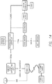
- the imaging system includes an automated process for capturing, editing, storing, retrieving and compositing orbital shot footage.
- the system includes a motion controlled armature (or series of booms) which rotates the camera, lights and backdrop around the patient at a repeatable rate.
- the imaging device can be programmed (or manually moved) to stop at any position within the orbit, allowing the camera to pause at one or more points through the orbit.
- lighting can be programmed to change intensity, color temperature or source/direction.
- the operator initializes the system using a touchscreen and enters patient metadata (e.g., name, surgical procedure, etc.).
- the patient is positioned, either seated or standing, under the axis of rotation, with the assistance of an eye safe laser (or other positioning device).
- an eye safe laser or other positioning device.
- the operator reaches overhead and lowers the camera and backdrop into a fixed position for the scan.
- the camera elevation can be set over a wide range (e.g., 6" to 80") to scan any horizontal band of the patient's body.
- a 360 degree camera imaging system comprising a first horizontal boom having a first end, a second end, and a middle section; a second horizontal boom having a first end and a second end; a first vertical arm having a first end and a second end; a second vertical arm having a first end and a second end; and a mounting bracket.
- the first horizontal boom is connected to the first end of the second horizontal boom by a first rotatable pivot proximate the middle section of the first horizontal boom, and the second end of the second horizontal boom is connected to the mounting bracket.
- the first end of the first vertical arm is affixed to the first end of the first horizontal boom, and the first end of the second vertical arm is affixed to the second end of the first horizontal boom.
- a camera is mounted to the first vertical arm, and a backdrop is mounted to the second vertical arm.
- the second end of the second horizontal boom is connected to the mounting bracket by a second rotatable pivot.
- the backdrop is mounted to the second vertical arm by way of a third rotatable pivot.
- a light is mounted on the first vertical arm.
- a second light mounted on the second vertical arm, proximate the first end of the second vertical arm.
- the camera is a video camera.
- the 360 degree camera imaging system further comprises a second camera.
- the second camera is a still camera.
- an electric motor is affixed to the second horizontal boom.
- the electric motor is affixed proximate the first rotatable pivot.
- the 360 degree camera imaging system further comprises a color scale.
- the 360 degree camera imaging system further comprises a light emitting diode centering light.
- a 360 degree camera imaging system comprising a horizontal boom having a first end, a second end, and a middle section; a first vertical arm having a first end and a second end; a second vertical arm having a first end and a second end; and a rotatable pivot proximate the middle section of the horizontal boom.
- the first end of the first vertical arm is affixed to the first end of the first horizontal boom, and the first end of the second vertical arm is affixed to the second end of the first horizontal boom.
- a camera is mounted to the first vertical arm, and a backdrop is mounted to the second vertical arm.
- a method of using a 360 degree camera system to capture a set of before and after images of a subject comprising the steps of (1) positioning the subject in between a camera and a backdrop at a first position, (2) passing the camera in a generally circular path around the subject while using the camera to capture at least five images of at least a portion of the subject, so as to capture a first image set, (3) positioning the subject a second time in between the camera and the backdrop at approximately the first position, (4) passing the camera in a generally circular path around the subject while using the camera to capture at least five images of at least a portion of the subject, so as to capture a second image set, and (5) comparing the first image set to the second image set.
- the method further comprises the use of a second camera that is a still camera, which captures at least five images while the first image set is being captured and at least five images while the second image set is being captured.
- the first light is located generally in front of the subject, and a second light is located generally behind the subject.
- the rate of camera movement during capture of the first image set as compared to camera movement during capture of the second image set is substantially the same.
- a subset of images from the first image set are selected.
- a subset of images from the second image set are selected.
- the camera passes through at least about 360 degrees while capturing the first image set and through at least about 360 degrees while capturing the second image set.
- a first side-by-side image of the subject and at least a second side-by-side image of the subject are produced.
- the first side-by-side image of the subject includes an image from the first image set and an image from the second image set
- the second side-by-side image of the subject includes an image from the first image set and an image from the second image set.
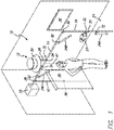
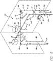
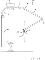
- FIG. 1 shows a preferred embodiment of a 360° imaging system 10 in accordance with a preferred embodiment of the present invention.
- the imaging system 10 can be used to take 360° pictures or videos of a person, object or scene positioned about a substantially vertical axis.
- the system 10 is preferably suspended from the ceiling and includes an imaging device that is pointed toward the object and is rotatable about the substantially vertical axis.
- the system 10 is used for imaging plastic surgery patients (e.g., to show before and after results).
- this is not a limitation on the present invention and it will be understood that the system 10 can be used for imaging any desired object.
- the imaging system 10 includes a rotation device 12 having a horizontally oriented boom 14 depending therefrom, first and second vertically oriented booms or arms 16 and 18, a backdrop 20, a counterweight 22, a lighting system 24 and an image capture device 26.
- the rotation device 12 is attached to or built into the ceiling of a room and includes a shaft or shafts 28 extending downwardly therefrom.
- the rotation device 12 includes a rotatable plate 30 to which the shafts 28 are attached. The opposite ends of the shafts are associated with the horizontal boom 14.
- the shafts 28 can be attached directly to the horizontal boom 14 or the shafts can include a slidable adjustment member 32 through which the horizontal boom 14 extends. It will be appreciated by those skilled in the art that any type of adjustment member that allows the horizontal boom 14 to be adjusted in a horizontal or axial direction is within the scope of the present invention.
- the slidable adjustment member 32 can be a tube 34 through which the horizontal boom 14 extends and that includes a set screw (not shown) that holds the horizontal boom 14 in place.
- first and second vertical arms 16 and 18 extend downwardly from horizontal boom 14.
- First vertical arm 16 includes image capture device 26 secured thereon.
- the height of image capture device 26 is adjustable. This can be done via a slidable adjustment member 32, as described above or by another known method.
- the first vertical arm 16 itself can be adjustable, for example by a telescopic adjustment member 36 or by providing for movement vertically of the entire first vertical arm 16.
- second vertical arm 18 includes backdrop 20 secured thereon. The height of backdrop 20 or second vertical arm 18 can also be adjustable. See, e.g., telescopic adjustment member 36 and arrow A1 in FIG. 3 .
- backdrop 20 can be raised or lowered, as is known in the art.
- first and second vertical arms 18 and 20 are also pivotally adjustable as shown by arrows A2 in FIG. 3 .
- pivotal adjustment can be provided by pivotal adjustment members 38 or the like.
- lighting system 24 includes a plurality of lights 24a, 24b and 24c. Any number of lights is within the scope of the present invention, and will depend on the needs of the particular project.
- the light system 24 includes a first light 24a disposed on first vertical arm 16 for front lighting of the subject, a second light 24b for downward front lighting and a third light 24c for lighting the backdrop 20.
- each of the lights 24 are adjustable, such as by a slidable adjustment member 32, as described above.
- the lights 24 can be clipped onto the horizontal boom 14 or first and/or second vertical arms 16 and 18.
- horizontal boom 14 includes counterweight 22 at or near the end thereof that is opposite the end that includes the image capture device 26.
- Counterweight 22 helps balance the system.
- the counterweight 22 can also be adjustable or movable to account for the weight of image capture device 26, lights 24, backdrop 20 and other components. Wires for carrying electricity, video signals, etc. are not shown in the drawings. However, those of ordinary skill in the art will understand the need for wires or conductors, etc. for powering the image capture device 26, lights 24, etc. It is also within the scope of the invention that the video and/or audio signals be sent wirelessly.
- the system 10 includes a monitor 40 that displays the image being captured by the image capture device 26.
- the monitor 40 can also be used to play back the captured image(s).
- the image capture device 26 and monitor are in electrical communication via wires or wirelessly.
- the imaging system 10 includes a plumb line 41 that extends downwardly from the horizontal boom 14 or the rotation device 12 and that is positioned substantially co-axially with the vertical axis defined by the rotation of the horizontal boom 14.
- the plumb line can be omitted.
- the subject to be filmed is placed in a position that is generally co-axial with the plumb line 41 and the vertical axis and is fixed in position.
- the subject can be seated or standing, as desired.
- the horizontal boom 14 is then rotated about the vertical axis with the image capture device 26 at one end and the background 20 attached to the opposite end.
- the image capture device 26 travels 360° around the subject obtaining video imaging of the subject.
- the subject is always positioned between the image capture device 26 and the back drop 20.
- the counterweight 22 is positioned such that it helps maintain balance of the system so that the image capturing device 26 moves in a 360° arc in as close to a perfect circle as possible.
- the counterweight 22 helps prevent the image capturing device from moving up and down or swinging left to right, as it moves in a circle and captures the desired image.
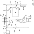
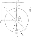
- FIGS. 4-5 shows the imaging system 10 together with a centering system 52.
- centering system 52 includes three cameras or image capturing devices 54a, 54b and 54c positioned such that they are directed toward the point where the object to be imaged is optimally centered. These cameras are positioned to capture the front view (x-axis camera 54a), side or lateral view (y-axis camera 54b) and top view (z-axis camera 54c).
- the images from these cameras 54a-54c are communicated to one or more monitors 56a, 56b and 56c where the user of the system 52 can position the object to be filmed as desired. It will be understood that the images can be positioned on a single monitor or on separate monitors. In another embodiment, the images can be shown on monitor 40.
- the three monitors 56a-56c are positioned on the wall and each include circles or markers 58 thereon that represent the optimal centered position.
- the surgeon can tell the patient to move their head, left, right, back, forth, etc. until their head is positioned as desired by the surgeon. This arrangement helps with repeatability between the before and after images.
- cameras 54a-54c are movable.
- x-axis camera 54a and y-axis camera 54b can be moved vertically depending on what portion of a patient is to be imaged.
- the x-axis camera 54a and y-axis camera 54b can be mounted on an arm 60 and include a slidable adjustment member 32, It should be understood that the x-axis camera 54a and y-axis camera 54b are usually positioned at the same height vertically.
- the z-axis camera 54c aids in positioning the patient along the center axis
- the x-axis camera 54a and y-axis camera 54b aid the user in finding the desired horizontal level to be imaged.
- cameras 54a-54b are independent of camera 26 and are preferably only used to center the patient. Camera 26 is used to image the patient as desired.
- the type of centering system used is not a limitation on the present invention.
- the system 10 can include multiple image capture devices 26.
- the system 10 can include multiple image capture devices 26 on the first vertical arm 16, thereby allowing a larger vertical image capture area.
- the system 10 can include a third vertical arm 42 that includes a second image capture device 44.
- the system 10 can include a second horizontal boom 46, fourth vertical arm 48 and second backdrop 50. Any number of image capture devices, backdrops and associated booms or arms is within the scope of the present invention.
- the system 10 can be used for preoperative evaluation of the face, the body or extremities to assess the aging process or deformity.
- the patient is seated as desired along the center axis, either by using the plumb line 41, centering system 52 or other centering methodology.
- the image capturing device 26 is then rotated 360° about the patient and the images are taken.
- the image capturing device 26 is rotated by hand. In other words, the user pushes or pulls the image capturing device 26 via the horizontal boom 14, first vertical arm 16 or other part of the system in a controlled manner around the patient.
- the rotation device 12 can be motorized and controlled remotely, by a switch, by computer or the like.
- the image capture device 26 is a video camera.
- the camera is a SONY® blu ray quality video camera that captures at least thirty frames per second as it passes around the patient. With this set up, the user can take any frame desired to make a photograph that can be used in patient evaluation, before and after pictures, etc.
- the system 10 can be used so that the before and after images are standardized or taken under exactly the same conditions.
- the before and after images are taken using the same system 10, in the same location, with the patient positioned along the center axis, with approximately the same focal length from the patient and in a relatively dark room. Therefore, because the lighting system 24 travels with the image capturing device 26 the before and after images are relatively consistent.
- the user after image capture pre and post-op, the user now has before and after dynamic three dimensional images and can also choose to select specific two dimensional images (or pictures) as desired.
- the standard set of pictures of a patient is six different views.
- an image capture device 26 that captures thirty frames per second, even if the patient blinks or twitches or the like, with all of the separate images, a user will be able to find six separate images from the before and after image capturing sessions that help make an adequate comparison. This can be useful for showing to the patients, for marketing purposes or for a publication or paper authored by the plastic surgeon.
- the captured images can be used for patient evaluation both before and after surgery.
- the images can be used with a prospective patient to point out areas that could use some work.
- the plastic surgeon sits down with the patient and reviews the video clip rotating the patient's head, chest, abdomen or other body part in space, evaluating fat content, skin laxity, wrinkles.
- the surgeon can look at the before and after head images next to each other and rotate them and look at an oblique view of the cheek to see if the results are satisfactory of if more fat needs to be injected.
- the system 10 can also be used in the operating room when the patient is under general anesthesia so that the captured image(s) are free of blinking, movement, etc.
- the system 10 can also be used in the assessing of motor nerve function and facial nerve function and/or nerve function anywhere on the body by using the dynamic three-dimensional image.
- the imaging system 10 can be used in conjunction with placing the 3D markers on the skin or adjacent thereto.
- 3D markers for motion capture and the like are known. Accordingly, a description thereof will be omitted.
- FIGS. 7-8 show another embodiment of a 360° imaging system 200 that includes two systems 10a and 10b as described above, that operate in conjunction with one another.
- this system 100 can be used to film two subjects that are each positioned under the rotation device 12 and co-axial with the substantially vertical axis defined by the rotation device 12.
- one system 10a has a shorter horizontal boom 14 than the other system 10b. This allows the booms 14 to rotate without components hitting one another.
- the systems 10a and 10b are positioned so that the first system 10a can rotate within the second system 10b.
- the horizontal booms 14 are positioned at different heights to also allow movement without components hitting one another. This can be done by positioning the rotation devices 12 at different heights or providing different length shafts 28 and positioning the systems 10a and 10b as shown in FIG. 9 .
- the system includes an arm 64 on which camera 26 is mounted and that moves horizontally (via telescoping or the like - see the arrows in FIG. 9 ) for close-ups and the like.
- the dual 360° imaging system 100 can be used in the film industry. For example, it can be used as a method for pre-visualization. It can be used to shoot scenes quickly with two actors who are each positioned under one of the rotation devices 12 and recite their lines. After shooting the scene and rotating each of the cameras 26 as desired, together with the backdrop 20 (which can be a blue screen or the like), the user has different angles to choose from without having to re-rig the camera, as has been done in the past.
- the dual 360° imaging system 100 allows a user to keep running a scene and have a plurality of different angles to choose from afterwards. And, the blue screen backdrop 20 stays lit behind the subject and the subject stays evenly lit because little changes between the camera 26 and the subject.
- the subjects are each positioned on stools (or they can be standing) underneath the rotation devices of each of the systems. Then the cameras can separately be rotated around the two subjects as desired.
- the system can include the ability to move the camera in or out, i.e., in a horizontal direction. This can be done on an arm that moves horizontally, similar to the arms moving vertically described above.
- the system can include a telescoping member on which the camera is mounted and that moves the camera toward and away from the subject.
- the movement of the system is automated. Therefore, in an exemplary use, a camera can move around the subject and then push in for a close up or pull back as desired. In a preferred embodiment, this can be done automatically at the sound of the director's voice.
- the imaging system 10 can be portable.
- the system 10 includes a stand 60 or the like that includes an arm 62 that suspends the system 10 above the ground.
- the stand 60 can be configured to be weighted down by being filled with water, sand or other material, similar to outdoor portable basketball systems.
- the system can be positioned on a dolly or track so that the entire system can be moved horizontally and still be rotatable.
- imaging system is used to capture and compare pre-surgical (or pre-event) images to post-surgical (or post-event) images of patients undergoing cosmetic procedures.
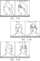
- the image capturing system is configured to produce video as synchronized orbital shots of the patient. See, e.g., the images in FIGS. 11A-11C , which show a series of before and after images at different stages of a 360° rotation. Therefore, the viewer can see two rotating images next to each other that rotate in synchrony as a result of the images captured by the 360° imaging system.
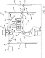
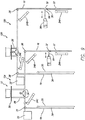
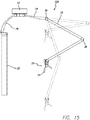
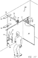
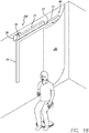
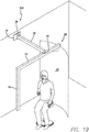
- FIGS. 12-15 show another preferred embodiment of a 360° imagining system 200.
- the system 200 includes an upper boom 14, first and second downwardly extending vertical arms 16 and 18, backdrop 20 and camera or imaging device 26.
- first downwardly extending vertical arm 16 includes joints or pivotal adjustment members 38 that allow camera or imaging device 26, and the assembly 202 in which it is housed, along with the lights 24, to movable upward and downwardly or toward or away from the subject to be imaged.
- the 360° imaging system can be used in many different settings.
- the system can be used by a dermatologist or other doctor to image a patient's skin to capture before and after images to observe changes over time in moles and other skin conditions.
- the system can also be used in a retail setting (e.g., a dressing room in a store) to allow a shopper to obtain a 360° image of the shopper wearing an outfit, shirt, pants, hat, etc.
- the system can include means for downloading the image to a memory device, such as a flash drive, thumb drive, the shopper's phone, etc. This can be done wirelessly or via a data connection such as a USB or other known connection.
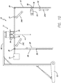
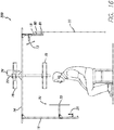
- FIGS. 16-19 show another preferred embodiment of a 360° imaging system 300 that can fold flat or nearly flat against a wall or other surface when not in use (as depicted in FIG. 18 ).
- the system 300 includes a first horizontal boom 14, first and second vertical arms 16 and 18, backdrop 20, and camera 26.
- the system 300 is intended to be mounted to a wall, floor, or ceiling of a room or other fixture by way of mounting brackets 78 and 79.
- a single mounting bracket also may be used (as depicted by mounting bracket 78 in FIGS. 18 and 19 ).
- Camera 26 is intended to be a video camera, though it is contemplated that camera 26 could equally be a still camera, or any other imaging device known to a person of ordinary skill in the art (including any and all general or specific imaging devices discussed herein with respect to other embodiments). Moreover, multiple cameras (in any combination of video cameras, still cameras, or other imaging devices known to persons of skill or as discussed herein with respect to other embodiments), are contemplated and intended to be within the scope of the present invention.
- the system 300 includes a front lighting system 70, which includes lights 71 and 72.
- the system 300 includes a back fill light 73, which may be set at any angle, but is shown at a preferred angle of approximately 45 degrees.
- Backdrop 20, which may be flat (as depicted in FIGS. 16-17 ) or curved (as depicted in FIGS. 18-19 ), is attached to vertical arm 18 by way of pivots 80 and 81. It is contemplates that backdrop 20 may be attached to vertical arm 18 by way of a single pivot or any other fastening device or devices known to a person of ordinary skill in the art.
- Backdrop 20 also may be attached directly to first horizontal boom 14 by way of one or more pivots or other fastening device(s) known to a person of ordinary skill in the art.
- the system 300 includes a motor system 74, which is preferably an electric motor, as shown in FIGS. 16 and 17 .
- motor system 74 operates to swing the second horizontal boom 75 to a position that is essentially perpendicular to the mounting bracket 78, and concurrently, motor system 74 operates to swing the first horizontal boom 14 into a position that is essentially parallel to the mounting bracket 78.
- the movement of the first horizontal boom 14 in this manner is depicted in FIGS. 18 and 19 .
- the backdrop 20 is mounted on one or more pivots (80 and/or 81), it is capable of rotating such that its plane becomes generally parallel to a patient's back when a patient is seated (as shown in FIGS. 16 , 17 , and 19 ), The movement of the backdrop 20 in this manner is depicted in FIGS. 18 and 19 .
- motor system 74 causes the first horizontal boom 14 to rotate about the second rotatable pivot 77, while camera 26 captures images at a frequency and quality that can vary or be adjusted by the operator.
- the movement of the first horizontal boom 14 and backdrop 20 can be achieved by hand or manual movement, without the use of a motor.
- system 300 may include a color scale light emitter, standing alone or directly connected to system 300, which allows for the standardization of color as among original and subsequent photographs.
- the system 300 also may include an LED (light emitting diode) centering light, either alone or directly connected to system 300, which projects a point of light at a standardized location ( e.g. , straight down from above), and allows the patient and/or camera system to be situated in the same or nearly the same position, as among original and subsequent photographs or image set capture.
- a patient or subject is positioned in between the camera 26 and the backdrop 20.
- the camera 26 travels in a generally circular path around the patient or subject, preferably at least 360 degrees (though any number of degrees is contemplated as being within the scope of the present invention).
- the camera 26 captures multiple images (preferably at least five (5), but any number is contemplated), during the time camera 26 passes around the subject and a first image set is captured.
- the above procedure is repeated, including the placement of the subject in the approximately or exactly the same position with respect to the original camera orientation, and a second image set is captured (again, preferably at least five (5) images, but any number is contemplated).
- the rate of camera movement during capture of the second image set may be the same or substantially the same as the rate of camera movement during capture of the first image set.
- a practitioner or other medical professional can then compare the first image set to the second image set and make any number of useful determinations or analyses, including the success of the surgery or medical procedure, progress of the patient post-surgery, and the like. From the resulting image sets, side-by-side comparisons also can be produced, as depicted, for example, in FIGS. 11A, 11B, and 11C .
Landscapes
- Engineering & Computer Science (AREA)
- General Engineering & Computer Science (AREA)
- Health & Medical Sciences (AREA)
- Life Sciences & Earth Sciences (AREA)
- Mechanical Engineering (AREA)
- Physics & Mathematics (AREA)
- General Physics & Mathematics (AREA)
- Animal Behavior & Ethology (AREA)
- Pathology (AREA)
- Biomedical Technology (AREA)
- Heart & Thoracic Surgery (AREA)
- Medical Informatics (AREA)
- Molecular Biology (AREA)
- Surgery (AREA)
- Biophysics (AREA)
- General Health & Medical Sciences (AREA)
- Public Health (AREA)
- Veterinary Medicine (AREA)
- Dentistry (AREA)
- Oral & Maxillofacial Surgery (AREA)
- Nuclear Medicine, Radiotherapy & Molecular Imaging (AREA)
- Radiology & Medical Imaging (AREA)
- Multimedia (AREA)
- Signal Processing (AREA)
- Accessories Of Cameras (AREA)
- Microscoopes, Condenser (AREA)
- Measurement Of The Respiration, Hearing Ability, Form, And Blood Characteristics Of Living Organisms (AREA)
- Studio Devices (AREA)
- Stereoscopic And Panoramic Photography (AREA)
Priority Applications (1)
| Application Number | Priority Date | Filing Date | Title |
|---|---|---|---|
| EP17169054.8A EP3270220A1 (en) | 2012-02-27 | 2013-02-27 | 360° imaging system |
Applications Claiming Priority (3)
| Application Number | Priority Date | Filing Date | Title |
|---|---|---|---|
| US201261603853P | 2012-02-27 | 2012-02-27 | |
| US201261667108P | 2012-07-02 | 2012-07-02 | |
| PCT/US2013/028092 WO2013130664A1 (en) | 2012-02-27 | 2013-02-27 | 360° imaging system |
Related Child Applications (1)
| Application Number | Title | Priority Date | Filing Date |
|---|---|---|---|
| EP17169054.8A Division EP3270220A1 (en) | 2012-02-27 | 2013-02-27 | 360° imaging system |
Publications (3)
| Publication Number | Publication Date |
|---|---|
| EP2820476A1 EP2820476A1 (en) | 2015-01-07 |
| EP2820476A4 EP2820476A4 (en) | 2015-12-23 |
| EP2820476B1 true EP2820476B1 (en) | 2017-05-03 |
Family
ID=49002502
Family Applications (2)
| Application Number | Title | Priority Date | Filing Date |
|---|---|---|---|
| EP13754794.9A Active EP2820476B1 (en) | 2012-02-27 | 2013-02-27 | 360° imaging system |
| EP17169054.8A Withdrawn EP3270220A1 (en) | 2012-02-27 | 2013-02-27 | 360° imaging system |
Family Applications After (1)
| Application Number | Title | Priority Date | Filing Date |
|---|---|---|---|
| EP17169054.8A Withdrawn EP3270220A1 (en) | 2012-02-27 | 2013-02-27 | 360° imaging system |
Country Status (12)
| Country | Link |
|---|---|
| US (1) | US9207518B2 (enExample) |
| EP (2) | EP2820476B1 (enExample) |
| JP (1) | JP6082036B2 (enExample) |
| KR (2) | KR102037017B1 (enExample) |
| CN (1) | CN104246599B (enExample) |
| AU (1) | AU2013226071B2 (enExample) |
| BR (1) | BR112014021250B1 (enExample) |
| CA (1) | CA2865398C (enExample) |
| ES (1) | ES2635988T3 (enExample) |
| MX (2) | MX350823B (enExample) |
| PT (1) | PT2820476T (enExample) |
| WO (1) | WO2013130664A1 (enExample) |
Families Citing this family (42)
| Publication number | Priority date | Publication date | Assignee | Title |
|---|---|---|---|---|
| US11309081B2 (en) | 2010-10-13 | 2022-04-19 | Gholam A. Peyman | Telemedicine system with dynamic imaging |
| US10456209B2 (en) | 2010-10-13 | 2019-10-29 | Gholam A. Peyman | Remote laser treatment system with dynamic imaging |
| WO2019014521A1 (en) * | 2017-07-13 | 2019-01-17 | Peyman Gholam A | DYNAMIC IMAGE RECOGNITION SYSTEM FOR SECURITY AND TELEMEDICINE |
| US10171734B2 (en) | 2012-02-27 | 2019-01-01 | Ovio Technologies, Inc. | Rotatable imaging system |
| US11756110B2 (en) * | 2012-11-30 | 2023-09-12 | Bwi Acquisition, Llc | Inspection and identification system and method |
| US12211092B2 (en) | 2012-11-30 | 2025-01-28 | Bwi Acquisition, Inc. | Vehicle imaging and inspection system |
| US20150134492A1 (en) * | 2013-11-11 | 2015-05-14 | Apple Inc. | Coordinated image manipulation |
| EP3078190A4 (en) * | 2013-12-03 | 2017-09-06 | Implicitcare, Llc | 360° imaging system |
| US20160102801A1 (en) * | 2014-10-08 | 2016-04-14 | Leadinway Co., Ltd. | Rotary device for image-capturing equipment |
| US9500314B2 (en) * | 2014-10-09 | 2016-11-22 | Yifei Zhang | Studio apparatus for mounting photography equipment |
| US10963749B2 (en) * | 2014-12-12 | 2021-03-30 | Cox Automotive, Inc. | Systems and methods for automatic vehicle imaging |
| DE102015102194B4 (de) * | 2015-02-16 | 2017-06-22 | Rainer Hahn | Vorrichtung zur optischen Rundum-Erfassung von Objekten |
| US10542223B2 (en) * | 2015-06-26 | 2020-01-21 | Twiin Media, LLC | Systems, methods, and apparatus for capturing multiple views of a subject |
| KR101701329B1 (ko) * | 2016-01-14 | 2017-02-02 | 오렌지몽키코리아 주식회사 | 촬영용 회전 테이블 및 이를 이용한 이미지 촬영 시스템 |
| JP6617964B2 (ja) * | 2016-02-19 | 2019-12-11 | 安雄 人見 | Tvカメラ取付器具 |
| FR3048579B1 (fr) * | 2016-03-01 | 2018-04-06 | Emmanuel Elard | Commande d'un dispositif de prise de vue permettant la comparaison de deux videos |
| WO2018031482A1 (en) * | 2016-08-08 | 2018-02-15 | Ovio Technologies, Inc. | Rotatable imaging system |
| JP6551687B2 (ja) * | 2016-10-11 | 2019-07-31 | 株式会社Cubic | 3d形状生成のための被写体全周囲撮像装置 |
| US10254631B2 (en) * | 2016-12-01 | 2019-04-09 | Phillip ASKEW | Imaging platform, in particular for imaging people |
| US10048516B2 (en) * | 2016-12-08 | 2018-08-14 | Perfect Vision Technology (Hk) Ltd. | Methods and systems for measuring human faces and eyeglass frames |
| WO2018106242A1 (en) * | 2016-12-08 | 2018-06-14 | Perfect Vision Technology (Hk) Ltd. | Methods and systems for measuring human faces for fitting, selecting, and optimizing eyeglasses |
| KR20180082818A (ko) * | 2017-01-11 | 2018-07-19 | 한창엽 | 다관절 카메라부가 구비된 촬영 장치 |
| RU171260U1 (ru) * | 2017-01-23 | 2017-05-25 | Александр Александрович Усольцев | Фотостенд |
| US10864044B2 (en) * | 2017-03-14 | 2020-12-15 | Smith & Nephew, Inc. | Systems and methods for measuring bone joint laxity |
| KR102002279B1 (ko) * | 2017-04-06 | 2019-07-23 | 한국한의학연구원 | 3차원 안면 진단 장치 |
| CA3068065A1 (en) | 2017-06-21 | 2018-12-27 | H3Alth Technologies Inc. | System, method and kit for 3d body imaging |
| CN107237965B (zh) * | 2017-07-17 | 2022-11-29 | 泰州市创新电子有限公司 | 一种升降结构及其升降支架 |
| US10791268B2 (en) | 2018-02-07 | 2020-09-29 | Structionsite Inc. | Construction photograph integration with 3D model images |
| US10339384B2 (en) | 2018-02-07 | 2019-07-02 | Structionsite Inc. | Construction photograph integration with 3D model images |
| CN110131532B (zh) * | 2018-02-08 | 2024-09-03 | 泰科电子(上海)有限公司 | 成像设备 |
| US11087446B2 (en) * | 2018-03-25 | 2021-08-10 | Matthew Henry Ranson | Automated arthropod detection system |
| US10467758B1 (en) | 2018-07-13 | 2019-11-05 | Structionsite Inc. | Imagery-based construction progress tracking |
| US10628989B2 (en) | 2018-07-16 | 2020-04-21 | Electronic Arts Inc. | Photometric image processing |
| US11022861B2 (en) * | 2018-07-16 | 2021-06-01 | Electronic Arts Inc. | Lighting assembly for producing realistic photo images |
| KR102385341B1 (ko) * | 2019-03-05 | 2022-04-12 | 박재흥 | 회전식 촬영기구 |
| DE102019110848A1 (de) * | 2019-04-26 | 2020-10-29 | FotoFinder Systems GmbH | Vorrichtung zur Erzeugung einer Ganzkörperabbildung |
| CN110342361A (zh) * | 2019-07-16 | 2019-10-18 | 北京一数科技有限公司 | 一种电梯广告投影装置 |
| CN111810777A (zh) * | 2020-06-17 | 2020-10-23 | 安徽超清科技股份有限公司 | 一种智能人体特征识别摄像机 |
| CN112682635B (zh) * | 2020-12-18 | 2022-08-30 | 李少华 | 博物馆文物三维扫描数据采集平台 |
| CN112780925A (zh) * | 2020-12-19 | 2021-05-11 | 王旭 | 一种多功能的城市治安监控杆 |
| CN112770028A (zh) * | 2020-12-31 | 2021-05-07 | 中铝智能科技发展有限公司 | 一种基于ar和vr的远程巡检系统 |
| CH718807B9 (it) * | 2021-07-12 | 2024-10-15 | Physei Sa | Apparato e metodo per la ripresa fotografica di oggetti. |
Family Cites Families (35)
| Publication number | Priority date | Publication date | Assignee | Title |
|---|---|---|---|---|
| US706459A (en) | 1898-01-20 | 1902-08-05 | Willy Alfred Carl Selke | Apparatus for copying models. |
| US2140602A (en) | 1937-10-02 | 1938-12-20 | Luther G Simjian | Multiple pose photographic apparatus |
| US2448084A (en) * | 1945-04-02 | 1948-08-31 | Valter V Davis | Scanning camera |
| CH519178A (fr) | 1969-06-20 | 1972-02-15 | Cruickshank John S | Installation de prise de vue |
| US3970835A (en) | 1975-07-07 | 1976-07-20 | Crete Richard C | Photographic light support apparatus |
| US4236795A (en) | 1979-01-18 | 1980-12-02 | H. George Brennan | Precision photographic documentation apparatus |
| AT367552B (de) | 1979-05-11 | 1982-07-12 | Chlestil Gustav Dkfm Ing | Verfahren zur fotografischen herstellung von datentraegern fuer die reproduktion dreidimensionaler objekte, vorrichtung zur durch- fuehrung des verfahrens und reproduktionseinrichtung |
| US4571638A (en) | 1983-05-02 | 1986-02-18 | Datacopy Corporation | Random-access electronic camera |
| JPH0192732A (ja) | 1987-04-15 | 1989-04-12 | Takara Isu Kogyo Kk | 患者の顔面規格写真撮影装置 |
| DE3931080A1 (de) * | 1989-09-18 | 1991-03-28 | Bbc Reaktor Gmbh | Verfahren und einrichtung zum ferngesteuerten positionieren eines pruefgeraetes mit hilfe einer dem pruefgeraet zugeordneten fernsehkamera |
| US6633328B1 (en) | 1999-01-05 | 2003-10-14 | Steris Corporation | Surgical lighting system with integrated digital video camera |
| JP2001169152A (ja) * | 1999-12-06 | 2001-06-22 | Minolta Co Ltd | 電子カメラ、電子カメラの表示状態調整方法、および記録媒体 |
| FR2813961B1 (fr) * | 2000-09-13 | 2003-05-16 | Jean Michel Dbjay | Cintre de prise de vue objet (vr) |
| TWI274289B (en) | 2001-02-19 | 2007-02-21 | Olympus Corp | Image comparing device, image comparing method and program for executing image comparison in computer recording medium |
| JP2002280440A (ja) * | 2001-03-16 | 2002-09-27 | Matsushita Electric Ind Co Ltd | 検査装置における回転ステージ自動位置補正制御方法 |
| JP2003021859A (ja) * | 2001-07-09 | 2003-01-24 | Konica Corp | 撮影用ガイド、人物写真撮影装置、人物写真プリント装置 |
| AUPS143702A0 (en) * | 2002-04-02 | 2002-05-09 | van der Linden, Garrath | Camera mount |
| JP4262454B2 (ja) * | 2002-07-30 | 2009-05-13 | オリンパス株式会社 | 手術用観察装置 |
| US7039220B2 (en) * | 2002-08-14 | 2006-05-02 | C-Scan, L.L.P. | Methods and apparatus for the dimensional measurement of livestock using a single camera |
| FR2856158B1 (fr) * | 2003-06-13 | 2005-08-19 | Lionel Giacomuzzi | Dispositif pour la prise de photographie |
| JP2005038293A (ja) | 2003-07-17 | 2005-02-10 | Milford:Kk | 顧客データ管理方法及び顧客データ管理システム |
| WO2005098476A1 (en) | 2004-03-29 | 2005-10-20 | Evolution Robotics, Inc. | Method and apparatus for position estimation using reflected light sources |
| JP2005316051A (ja) | 2004-04-28 | 2005-11-10 | Asahi Roentgen Kogyo Kk | カメラ回転装置 |
| FR2870948B1 (fr) * | 2004-05-25 | 2006-09-01 | Sagem | Dispositif de positionnement d'un utilisateur par affichage de son image en miroir, dispositif de capture d'images et procede de positionnement correspondants |
| TWI274124B (en) * | 2005-01-06 | 2007-02-21 | Jia-Duo Weng | 3D object surrounding photographic rack |
| KR100707790B1 (ko) * | 2005-08-31 | 2007-04-13 | 주식회사바텍 | 파노라마 영상 촬영장치의 환자 정렬장치 |
| US7502174B2 (en) * | 2006-11-23 | 2009-03-10 | General Electric Company | System and method for imaging |
| DE102007052300A1 (de) * | 2007-10-31 | 2009-05-07 | Peter Weigelt | Stativ zum Photografieren von Objekten |
| JP5047830B2 (ja) * | 2008-02-07 | 2012-10-10 | 株式会社タイトー | 撮影装置及び撮影情報通信システム |
| KR20100011301A (ko) * | 2008-07-24 | 2010-02-03 | (주)이우테크놀로지 | 치과용 엑스선촬영장치의 검진자 두부 정렬시스템 및정렬시스템의 제어방법 |
| CN101452186A (zh) * | 2008-12-30 | 2009-06-10 | 刘洋 | 一种可绕被摄物旋转摄像的摄像平台 |
| US8351770B2 (en) | 2009-03-16 | 2013-01-08 | Raytheon Company | Imaging station and method for repeatable alignment of images |
| DE102009033110A1 (de) * | 2009-07-15 | 2011-02-03 | Byk Gardner Gmbh | Vorrichtung zum Untersuchen strukturierter Oberflächen |
| US20110116782A1 (en) | 2009-11-18 | 2011-05-19 | Scott L Dean | Camera support |
| CN101794069B (zh) * | 2010-01-29 | 2011-08-31 | 于辉 | 一种全景成像仪 |
-
2013
- 2013-02-27 BR BR112014021250-3A patent/BR112014021250B1/pt active IP Right Grant
- 2013-02-27 PT PT137547949T patent/PT2820476T/pt unknown
- 2013-02-27 MX MX2016005093A patent/MX350823B/es unknown
- 2013-02-27 MX MX2014010240A patent/MX341042B/es active IP Right Grant
- 2013-02-27 ES ES13754794.9T patent/ES2635988T3/es active Active
- 2013-02-27 JP JP2014559998A patent/JP6082036B2/ja active Active
- 2013-02-27 EP EP13754794.9A patent/EP2820476B1/en active Active
- 2013-02-27 CA CA2865398A patent/CA2865398C/en active Active
- 2013-02-27 EP EP17169054.8A patent/EP3270220A1/en not_active Withdrawn
- 2013-02-27 AU AU2013226071A patent/AU2013226071B2/en active Active
- 2013-02-27 US US13/779,543 patent/US9207518B2/en active Active
- 2013-02-27 CN CN201380021017.9A patent/CN104246599B/zh active Active
- 2013-02-27 KR KR1020187018997A patent/KR102037017B1/ko active Active
- 2013-02-27 WO PCT/US2013/028092 patent/WO2013130664A1/en not_active Ceased
- 2013-02-27 KR KR1020147026755A patent/KR20140140047A/ko not_active Ceased
Also Published As
| Publication number | Publication date |
|---|---|
| KR20140140047A (ko) | 2014-12-08 |
| KR20180081166A (ko) | 2018-07-13 |
| CA2865398A1 (en) | 2013-09-06 |
| CN104246599B (zh) | 2017-08-29 |
| US20130222684A1 (en) | 2013-08-29 |
| ES2635988T3 (es) | 2017-10-05 |
| BR112014021250B1 (pt) | 2022-01-11 |
| AU2013226071B2 (en) | 2016-06-09 |
| BR112014021250A2 (pt) | 2020-11-10 |
| MX350823B (es) | 2017-09-21 |
| EP3270220A1 (en) | 2018-01-17 |
| JP2015516585A (ja) | 2015-06-11 |
| WO2013130664A8 (en) | 2013-12-19 |
| CN104246599A (zh) | 2014-12-24 |
| CA2865398C (en) | 2018-10-23 |
| WO2013130664A1 (en) | 2013-09-06 |
| MX2014010240A (es) | 2015-03-19 |
| PT2820476T (pt) | 2017-08-09 |
| EP2820476A4 (en) | 2015-12-23 |
| AU2013226071A1 (en) | 2014-09-25 |
| JP6082036B2 (ja) | 2017-02-15 |
| EP2820476A1 (en) | 2015-01-07 |
| KR102037017B1 (ko) | 2019-11-26 |
| US9207518B2 (en) | 2015-12-08 |
| MX341042B (es) | 2016-08-05 |
Similar Documents
| Publication | Publication Date | Title |
|---|---|---|
| EP2820476B1 (en) | 360° imaging system | |
| US10171734B2 (en) | Rotatable imaging system | |
| US9408540B2 (en) | Rotatable imaging system | |
| US9060125B2 (en) | 360° imaging system | |
| CN108761992A (zh) | 一种内置稳定器的3d全景相机 | |
| KR200467210Y1 (ko) | 안면 화상 데이터 획득장치 | |
| KR101447233B1 (ko) | 파노라마 촬영장치 | |
| US10548683B2 (en) | Surgical procedure handheld electronic display device and method of using same | |
| CN108696717A (zh) | 主动影像追踪方法、影像追踪辅助装置与嵌入式系统 | |
| JP6055162B1 (ja) | 動画撮影表示装置 | |
| US10260672B2 (en) | Method and apparatus for spin photography | |
| US12478163B2 (en) | Makeup machine with a compact housing | |
| WO2015085009A2 (en) | 360° imaging system | |
| WO2018031482A1 (en) | Rotatable imaging system | |
| CN110620912B (zh) | 运笔过程展示和记录设备及系统 | |
| US10845681B1 (en) | Camera apparatus for hiding a camera operator while capturing 360-degree images or video footage | |
| US12419445B1 (en) | Mirror assembly and method of use | |
| JP3098827U (ja) | 撮影システム及び撮影制御装置 | |
| CN213522118U (zh) | 一种显示装置、梳妆台及镜子 | |
| CA3235797A1 (en) | Makeup machine with automatically-controlled spray head movements | |
| TW201503686A (zh) | 減少被攝像物體發生脫離拍攝視窗的裝置及方法 |
Legal Events
| Date | Code | Title | Description |
|---|---|---|---|
| PUAI | Public reference made under article 153(3) epc to a published international application that has entered the european phase |
Free format text: ORIGINAL CODE: 0009012 |
|
| 17P | Request for examination filed |
Effective date: 20140905 |
|
| AK | Designated contracting states |
Kind code of ref document: A1 Designated state(s): AL AT BE BG CH CY CZ DE DK EE ES FI FR GB GR HR HU IE IS IT LI LT LU LV MC MK MT NL NO PL PT RO RS SE SI SK SM TR |
|
| AX | Request for extension of the european patent |
Extension state: BA ME |
|
| DAX | Request for extension of the european patent (deleted) | ||
| RA4 | Supplementary search report drawn up and despatched (corrected) |
Effective date: 20151125 |
|
| RIC1 | Information provided on ipc code assigned before grant |
Ipc: F16M 11/18 20060101ALI20151119BHEP Ipc: G03B 15/00 20060101AFI20151119BHEP Ipc: G03B 17/56 20060101ALI20151119BHEP Ipc: A61B 5/00 20060101ALI20151119BHEP |
|
| RIC1 | Information provided on ipc code assigned before grant |
Ipc: G03B 17/56 20060101ALI20160919BHEP Ipc: G03B 15/00 20060101AFI20160919BHEP Ipc: A61B 5/00 20060101ALI20160919BHEP Ipc: F16M 11/18 20060101ALI20160919BHEP |
|
| GRAP | Despatch of communication of intention to grant a patent |
Free format text: ORIGINAL CODE: EPIDOSNIGR1 |
|
| INTG | Intention to grant announced |
Effective date: 20161115 |
|
| GRAS | Grant fee paid |
Free format text: ORIGINAL CODE: EPIDOSNIGR3 |
|
| GRAA | (expected) grant |
Free format text: ORIGINAL CODE: 0009210 |
|
| AK | Designated contracting states |
Kind code of ref document: B1 Designated state(s): AL AT BE BG CH CY CZ DE DK EE ES FI FR GB GR HR HU IE IS IT LI LT LU LV MC MK MT NL NO PL PT RO RS SE SI SK SM TR |
|
| REG | Reference to a national code |
Ref country code: GB Ref legal event code: FG4D |
|
| REG | Reference to a national code |
Ref country code: AT Ref legal event code: REF Ref document number: 890630 Country of ref document: AT Kind code of ref document: T Effective date: 20170515 Ref country code: CH Ref legal event code: EP |
|
| REG | Reference to a national code |
Ref country code: IE Ref legal event code: FG4D |
|
| REG | Reference to a national code |
Ref country code: DE Ref legal event code: R096 Ref document number: 602013020648 Country of ref document: DE |
|
| REG | Reference to a national code |
Ref country code: PT Ref legal event code: SC4A Ref document number: 2820476 Country of ref document: PT Date of ref document: 20170809 Kind code of ref document: T Free format text: AVAILABILITY OF NATIONAL TRANSLATION Effective date: 20170802 |
|
| REG | Reference to a national code |
Ref country code: NL Ref legal event code: MP Effective date: 20170503 |
|
| REG | Reference to a national code |
Ref country code: AT Ref legal event code: MK05 Ref document number: 890630 Country of ref document: AT Kind code of ref document: T Effective date: 20170503 |
|
| REG | Reference to a national code |
Ref country code: LT Ref legal event code: MG4D |
|
| REG | Reference to a national code |
Ref country code: ES Ref legal event code: FG2A Ref document number: 2635988 Country of ref document: ES Kind code of ref document: T3 Effective date: 20171005 |
|
| PG25 | Lapsed in a contracting state [announced via postgrant information from national office to epo] |
Ref country code: NO Free format text: LAPSE BECAUSE OF FAILURE TO SUBMIT A TRANSLATION OF THE DESCRIPTION OR TO PAY THE FEE WITHIN THE PRESCRIBED TIME-LIMIT Effective date: 20170803 Ref country code: HR Free format text: LAPSE BECAUSE OF FAILURE TO SUBMIT A TRANSLATION OF THE DESCRIPTION OR TO PAY THE FEE WITHIN THE PRESCRIBED TIME-LIMIT Effective date: 20170503 Ref country code: FI Free format text: LAPSE BECAUSE OF FAILURE TO SUBMIT A TRANSLATION OF THE DESCRIPTION OR TO PAY THE FEE WITHIN THE PRESCRIBED TIME-LIMIT Effective date: 20170503 Ref country code: LT Free format text: LAPSE BECAUSE OF FAILURE TO SUBMIT A TRANSLATION OF THE DESCRIPTION OR TO PAY THE FEE WITHIN THE PRESCRIBED TIME-LIMIT Effective date: 20170503 Ref country code: AT Free format text: LAPSE BECAUSE OF FAILURE TO SUBMIT A TRANSLATION OF THE DESCRIPTION OR TO PAY THE FEE WITHIN THE PRESCRIBED TIME-LIMIT Effective date: 20170503 |
|
| PG25 | Lapsed in a contracting state [announced via postgrant information from national office to epo] |
Ref country code: BG Free format text: LAPSE BECAUSE OF FAILURE TO SUBMIT A TRANSLATION OF THE DESCRIPTION OR TO PAY THE FEE WITHIN THE PRESCRIBED TIME-LIMIT Effective date: 20170803 Ref country code: PL Free format text: LAPSE BECAUSE OF FAILURE TO SUBMIT A TRANSLATION OF THE DESCRIPTION OR TO PAY THE FEE WITHIN THE PRESCRIBED TIME-LIMIT Effective date: 20170503 Ref country code: RS Free format text: LAPSE BECAUSE OF FAILURE TO SUBMIT A TRANSLATION OF THE DESCRIPTION OR TO PAY THE FEE WITHIN THE PRESCRIBED TIME-LIMIT Effective date: 20170503 Ref country code: IS Free format text: LAPSE BECAUSE OF FAILURE TO SUBMIT A TRANSLATION OF THE DESCRIPTION OR TO PAY THE FEE WITHIN THE PRESCRIBED TIME-LIMIT Effective date: 20170903 Ref country code: SE Free format text: LAPSE BECAUSE OF FAILURE TO SUBMIT A TRANSLATION OF THE DESCRIPTION OR TO PAY THE FEE WITHIN THE PRESCRIBED TIME-LIMIT Effective date: 20170503 Ref country code: LV Free format text: LAPSE BECAUSE OF FAILURE TO SUBMIT A TRANSLATION OF THE DESCRIPTION OR TO PAY THE FEE WITHIN THE PRESCRIBED TIME-LIMIT Effective date: 20170503 Ref country code: NL Free format text: LAPSE BECAUSE OF FAILURE TO SUBMIT A TRANSLATION OF THE DESCRIPTION OR TO PAY THE FEE WITHIN THE PRESCRIBED TIME-LIMIT Effective date: 20170503 |
|
| PG25 | Lapsed in a contracting state [announced via postgrant information from national office to epo] |
Ref country code: EE Free format text: LAPSE BECAUSE OF FAILURE TO SUBMIT A TRANSLATION OF THE DESCRIPTION OR TO PAY THE FEE WITHIN THE PRESCRIBED TIME-LIMIT Effective date: 20170503 Ref country code: DK Free format text: LAPSE BECAUSE OF FAILURE TO SUBMIT A TRANSLATION OF THE DESCRIPTION OR TO PAY THE FEE WITHIN THE PRESCRIBED TIME-LIMIT Effective date: 20170503 Ref country code: RO Free format text: LAPSE BECAUSE OF FAILURE TO SUBMIT A TRANSLATION OF THE DESCRIPTION OR TO PAY THE FEE WITHIN THE PRESCRIBED TIME-LIMIT Effective date: 20170503 Ref country code: SK Free format text: LAPSE BECAUSE OF FAILURE TO SUBMIT A TRANSLATION OF THE DESCRIPTION OR TO PAY THE FEE WITHIN THE PRESCRIBED TIME-LIMIT Effective date: 20170503 Ref country code: CZ Free format text: LAPSE BECAUSE OF FAILURE TO SUBMIT A TRANSLATION OF THE DESCRIPTION OR TO PAY THE FEE WITHIN THE PRESCRIBED TIME-LIMIT Effective date: 20170503 |
|
| REG | Reference to a national code |
Ref country code: DE Ref legal event code: R097 Ref document number: 602013020648 Country of ref document: DE |
|
| RAP2 | Party data changed (patent owner data changed or rights of a patent transferred) |
Owner name: IC360 IMAGING, INC. |
|
| PG25 | Lapsed in a contracting state [announced via postgrant information from national office to epo] |
Ref country code: SM Free format text: LAPSE BECAUSE OF FAILURE TO SUBMIT A TRANSLATION OF THE DESCRIPTION OR TO PAY THE FEE WITHIN THE PRESCRIBED TIME-LIMIT Effective date: 20170503 |
|
| RAP2 | Party data changed (patent owner data changed or rights of a patent transferred) |
Owner name: OVIO TECHNOLOGIES, INC. |
|
| PLBE | No opposition filed within time limit |
Free format text: ORIGINAL CODE: 0009261 |
|
| STAA | Information on the status of an ep patent application or granted ep patent |
Free format text: STATUS: NO OPPOSITION FILED WITHIN TIME LIMIT |
|
| REG | Reference to a national code |
Ref country code: FR Ref legal event code: PLFP Year of fee payment: 6 |
|
| 26N | No opposition filed |
Effective date: 20180206 |
|
| PG25 | Lapsed in a contracting state [announced via postgrant information from national office to epo] |
Ref country code: SI Free format text: LAPSE BECAUSE OF FAILURE TO SUBMIT A TRANSLATION OF THE DESCRIPTION OR TO PAY THE FEE WITHIN THE PRESCRIBED TIME-LIMIT Effective date: 20170503 |
|
| REG | Reference to a national code |
Ref country code: DE Ref legal event code: R082 Ref document number: 602013020648 Country of ref document: DE Representative=s name: MARKS & CLERK (LUXEMBOURG) LLP, LU Ref country code: DE Ref legal event code: R081 Ref document number: 602013020648 Country of ref document: DE Owner name: OVIO TECHNOLOGIES, INC. (N.D.GES.D. STAATES DE, US Free format text: FORMER OWNER: IMPLICITCARE, LLC, WEST HOLLYWOOD, CALIF., US |
|
| REG | Reference to a national code |
Ref country code: CH Ref legal event code: PL |
|
| PG25 | Lapsed in a contracting state [announced via postgrant information from national office to epo] |
Ref country code: MC Free format text: LAPSE BECAUSE OF FAILURE TO SUBMIT A TRANSLATION OF THE DESCRIPTION OR TO PAY THE FEE WITHIN THE PRESCRIBED TIME-LIMIT Effective date: 20170503 |
|
| REG | Reference to a national code |
Ref country code: BE Ref legal event code: MM Effective date: 20180228 |
|
| PG25 | Lapsed in a contracting state [announced via postgrant information from national office to epo] |
Ref country code: LU Free format text: LAPSE BECAUSE OF NON-PAYMENT OF DUE FEES Effective date: 20180227 Ref country code: CH Free format text: LAPSE BECAUSE OF NON-PAYMENT OF DUE FEES Effective date: 20180228 Ref country code: LI Free format text: LAPSE BECAUSE OF NON-PAYMENT OF DUE FEES Effective date: 20180228 |
|
| PG25 | Lapsed in a contracting state [announced via postgrant information from national office to epo] |
Ref country code: IE Free format text: LAPSE BECAUSE OF NON-PAYMENT OF DUE FEES Effective date: 20180227 |
|
| PG25 | Lapsed in a contracting state [announced via postgrant information from national office to epo] |
Ref country code: BE Free format text: LAPSE BECAUSE OF NON-PAYMENT OF DUE FEES Effective date: 20180228 |
|
| PG25 | Lapsed in a contracting state [announced via postgrant information from national office to epo] |
Ref country code: MT Free format text: LAPSE BECAUSE OF NON-PAYMENT OF DUE FEES Effective date: 20180227 |
|
| PG25 | Lapsed in a contracting state [announced via postgrant information from national office to epo] |
Ref country code: TR Free format text: LAPSE BECAUSE OF FAILURE TO SUBMIT A TRANSLATION OF THE DESCRIPTION OR TO PAY THE FEE WITHIN THE PRESCRIBED TIME-LIMIT Effective date: 20170503 |
|
| PG25 | Lapsed in a contracting state [announced via postgrant information from national office to epo] |
Ref country code: HU Free format text: LAPSE BECAUSE OF FAILURE TO SUBMIT A TRANSLATION OF THE DESCRIPTION OR TO PAY THE FEE WITHIN THE PRESCRIBED TIME-LIMIT; INVALID AB INITIO Effective date: 20130227 |
|
| PG25 | Lapsed in a contracting state [announced via postgrant information from national office to epo] |
Ref country code: GR Free format text: LAPSE BECAUSE OF FAILURE TO SUBMIT A TRANSLATION OF THE DESCRIPTION OR TO PAY THE FEE WITHIN THE PRESCRIBED TIME-LIMIT Effective date: 20170503 Ref country code: MK Free format text: LAPSE BECAUSE OF NON-PAYMENT OF DUE FEES Effective date: 20170503 Ref country code: CY Free format text: LAPSE BECAUSE OF FAILURE TO SUBMIT A TRANSLATION OF THE DESCRIPTION OR TO PAY THE FEE WITHIN THE PRESCRIBED TIME-LIMIT Effective date: 20170503 |
|
| PG25 | Lapsed in a contracting state [announced via postgrant information from national office to epo] |
Ref country code: AL Free format text: LAPSE BECAUSE OF FAILURE TO SUBMIT A TRANSLATION OF THE DESCRIPTION OR TO PAY THE FEE WITHIN THE PRESCRIBED TIME-LIMIT Effective date: 20170503 |
|
| PGFP | Annual fee paid to national office [announced via postgrant information from national office to epo] |
Ref country code: PT Payment date: 20230123 Year of fee payment: 11 |
|
| PG25 | Lapsed in a contracting state [announced via postgrant information from national office to epo] |
Ref country code: PT Free format text: LAPSE BECAUSE OF NON-PAYMENT OF DUE FEES Effective date: 20240827 |
|
| PG25 | Lapsed in a contracting state [announced via postgrant information from national office to epo] |
Ref country code: PT Free format text: LAPSE BECAUSE OF NON-PAYMENT OF DUE FEES Effective date: 20240827 |
|
| PGFP | Annual fee paid to national office [announced via postgrant information from national office to epo] |
Ref country code: DE Payment date: 20250122 Year of fee payment: 13 |
|
| PGFP | Annual fee paid to national office [announced via postgrant information from national office to epo] |
Ref country code: ES Payment date: 20250303 Year of fee payment: 13 |
|
| PGFP | Annual fee paid to national office [announced via postgrant information from national office to epo] |
Ref country code: FR Payment date: 20250122 Year of fee payment: 13 |
|
| PGFP | Annual fee paid to national office [announced via postgrant information from national office to epo] |
Ref country code: IT Payment date: 20250121 Year of fee payment: 13 Ref country code: GB Payment date: 20250124 Year of fee payment: 13 |