EP2818389A1 - Portalanhänger für einen Routenzug - Google Patents
Portalanhänger für einen Routenzug Download PDFInfo
- Publication number
- EP2818389A1 EP2818389A1 EP14173441.8A EP14173441A EP2818389A1 EP 2818389 A1 EP2818389 A1 EP 2818389A1 EP 14173441 A EP14173441 A EP 14173441A EP 2818389 A1 EP2818389 A1 EP 2818389A1
- Authority
- EP
- European Patent Office
- Prior art keywords
- trailer
- portal
- section
- trolley
- rollers
- Prior art date
- Legal status (The legal status is an assumption and is not a legal conclusion. Google has not performed a legal analysis and makes no representation as to the accuracy of the status listed.)
- Granted
Links
Images


Classifications
-
- B—PERFORMING OPERATIONS; TRANSPORTING
- B66—HOISTING; LIFTING; HAULING
- B66F—HOISTING, LIFTING, HAULING OR PUSHING, NOT OTHERWISE PROVIDED FOR, e.g. DEVICES WHICH APPLY A LIFTING OR PUSHING FORCE DIRECTLY TO THE SURFACE OF A LOAD
- B66F9/00—Devices for lifting or lowering bulky or heavy goods for loading or unloading purposes
- B66F9/06—Devices for lifting or lowering bulky or heavy goods for loading or unloading purposes movable, with their loads, on wheels or the like, e.g. fork-lift trucks
-
- B—PERFORMING OPERATIONS; TRANSPORTING
- B62—LAND VEHICLES FOR TRAVELLING OTHERWISE THAN ON RAILS
- B62D—MOTOR VEHICLES; TRAILERS
- B62D53/00—Tractor-trailer combinations; Road trains
-
- B—PERFORMING OPERATIONS; TRANSPORTING
- B62—LAND VEHICLES FOR TRAVELLING OTHERWISE THAN ON RAILS
- B62B—HAND-PROPELLED VEHICLES, e.g. HAND CARTS OR PERAMBULATORS; SLEDGES
- B62B5/00—Accessories or details specially adapted for hand carts
- B62B5/0026—Propulsion aids
- B62B5/0079—Towing by connecting to another vehicle
-
- B—PERFORMING OPERATIONS; TRANSPORTING
- B62—LAND VEHICLES FOR TRAVELLING OTHERWISE THAN ON RAILS
- B62D—MOTOR VEHICLES; TRAILERS
- B62D53/00—Tractor-trailer combinations; Road trains
- B62D53/005—Combinations with at least three axles and comprising two or more articulated parts
-
- B—PERFORMING OPERATIONS; TRANSPORTING
- B62—LAND VEHICLES FOR TRAVELLING OTHERWISE THAN ON RAILS
- B62B—HAND-PROPELLED VEHICLES, e.g. HAND CARTS OR PERAMBULATORS; SLEDGES
- B62B2202/00—Indexing codes relating to type or characteristics of transported articles
- B62B2202/90—Vehicles
Definitions
- the present invention relates to a portal trailer for a tugger train.
- Tugger trains are used in the internal logistics to transport material on predetermined routes. Tugger trains consist of a non-rail guided towing vehicle and one or more trailers.
- a transport system for a forkliftless supply is known.
- a C-shaped trailer frame is used with four wheels, which has in its interior height-adjustable load-bearing devices.
- a portal trailer is known from Fig. 10, in which a front and a rear trailer section are connected to each other via a portal-shaped arch construction.
- the advantage of a portal trailer is that the recorded trolley from both sides in the Portal trailer can be inserted and thus more flexible in the internal logistics can be used.
- the invention has for its object to provide a portal trailer, which has a track as faithful as possible steering with the simplest possible structure and at the same time offers the opportunity to transport a trolley in a raised state.
- the portal trailer according to the invention is provided and intended for a tugger train.
- the portal trailer consists of a front, rear and a central trailer section, which are arranged one behind the other along the longitudinal direction of the portal trailer. Between two adjacent trailer sections is in each case a receiving area for a to be carried in the portal trailer trolley.
- the front and the middle trailer section are connected to each other via a portal-shaped arc.
- the middle and the rear trailer section are connected to each other via a portal-shaped arc.
- the middle trailer section has a pair of rollers.
- the rollers sometimes referred to as middle-axis steering, allow the portal trailer to follow the curve in the correct direction.
- the structure with three trailer sections and two portal arches, which result in an overall M-shaped portal trailer, is particularly simple and gets rid of due to the rollers mounted on the middle trailer section without an active steering.
- the rollers provided on the middle trailer section are each provided with an axis of rotation perpendicular to the trailer longitudinal direction.
- the rollers are preferably arranged rigidly on the central trailer portion and have mutually aligned axes of rotation.
- the middle trailer section is equipped with a lifting device, which makes it possible to lift the middle trailer section and the portal-shaped arches and the front and rear trailer section.
- the portal trailer according to the invention has a holding device for a trolley in the receiving area.
- the holding device has a profile rail on which rests the cart to be transported during transport.
- the use of a rail in the receiving area makes it possible to insert the trolley to be transported from both sides in the holding device. By lifting the portal trailer of the trolley is then on the rail and is raised with.
- each trailer section has laterally on opposite sides a portal strut which is connected to a portal strut of an adjacent trailer section via a gantry arch.
- the Trailer sections of the portal trailer are connected to each other at their outer ends by portal-shaped arches, consisting of a portal strut and a portal arch.
- a towing hook is provided on the front and / or rear trailer section.
- a trailer hitch may be provided on the rear and / or front trailer section.
- additional rollers are provided on the front and / or rear trailer section. When lifting the middle trailer section also lose these additional roles the ground contact.
- the additional rollers serve to better move and move the portal trailer in the non-raised state.
- the additional rollers are preferably designed as castors.
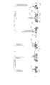
- Fig. 1 shows a transport or tugger train with a towing vehicle 10 and two towed trailers 12, 14.
- the illustrated trailer 12 and 14 are constructed substantially the same.
- the portal trailer 12 has a front trailer section 16, a central or middle trailer section 18 and a rear trailer section 20.
- the middle trailer section 18 is provided with rollers 22 on its outer sides.
- the rollers 22 of the central trailer section are provided with a comparatively large diameter, comparable to the wheels of the towing vehicle 10, so that the term "rollers" in the middle section also includes wheels.
- a trolley 24 is added between the middle trailer portion 18 and the rear trailer portion 20.
- the portal trailer can be used in both directions, so that front and rear trailer section are only for better orientation and not determine the direction of travel of the trailer.
- a portal strut 30, 32 is provided on the outer sides in each case.
- the central trailer section 18 has the portal struts 34 and 36, while on the rear trailer section 20, the portal struts 38 and 40 are provided.
- the portal struts 30 and 34 as well as the struts 32 and 36 are connected via a respective portal arch 42, 44 with each other.
- the portal struts 34 and 38 and 36 and 40 are connected to each other via the arches 46 and 48.
- the portal strut 30 may be integrally formed with a first half of the portal arch 40 and the portal strut 34 with a second, extending in the direction of the front trailer section Part of the portal arch to be connected in the middle.
- the distinction between portal strut and gantry arch refers only to the geometry and the spatial position and not on the portal-forming arc-forming components.
- the portal-shaped arches form an M-shaped structure for the portal trailer.
- Fig. 2a shows a portal trailer according to the invention, in which the trolleys 24 and 26 have been pushed laterally out of the portal trailer in different directions.
- the profile strips have an L-shaped profile, on which the trolleys 24, 26 are pushed.
- the middle trailer section 18 can be raised by a lifting device (not shown). By raising the distance of the profile strips 50b, 50c increases with respect to the ground, so that an inserted trolley 24, 26 is raised with. At the same time the portal-shaped arches and also the rear and the front trailer section are lifted, so that the profile strips 50a and 50d mitanhoben as holding devices for the trolleys.
- Fig. 2b shows the inserted between the trailer sections trolley, which rest on the rails as lifting devices.
- Fig. 3 shows the portal trailer according to the invention in its raised position, the wheels 22 of the portal trailer are on the ground and the trolleys 24, 26 and their wheels 52 are released from the ground.
- the two wheels 22 in the middle trailer portion 18 have aligned axes of rotation.
- a rigid axle between the wheels 22 may be provided.
- the steering wheels 22 must be able to rotate independently on this rigid axle, so that when cornering no transverse movement occurs.
- Fig. 3 additionally shows a tow bar 54, which is pivotally mounted on the front trailer section 16.
- a trailer hitch 56 which can accommodate a trained drawbar.
- Fig. 4 shows an alternative embodiment of the portal trailer according to the invention, in which the front and rear section 16 ', 20' additionally provided with castors 58, 60.
- the castors 58, 60 make it possible to prevent the rear or front trailer section from being placed on the ground when the portal trailer is lowered.
- the unloaded portal trailer can be well moved and positioned for further work.
Landscapes
- Engineering & Computer Science (AREA)
- Transportation (AREA)
- Mechanical Engineering (AREA)
- Chemical & Material Sciences (AREA)
- Combustion & Propulsion (AREA)
- Structural Engineering (AREA)
- Civil Engineering (AREA)
- Life Sciences & Earth Sciences (AREA)
- Geology (AREA)
- Handcart (AREA)
Abstract
Description
- Die vorliegende Erfindung betrifft einen Portalanhänger für einen Routenzug.
- Routenzüge, gelegentlich auch als Transportzüge bezeichnet, werden in der innerbetrieblichen Logistik eingesetzt, um Material auf vorgegebenen Routen zu transportieren. Routenzüge bestehen dabei aus einem nicht schienengeführten Schleppfahrzeug und einem oder mehreren Anhängern.
- Aus
DE 603 00 189 T2 ist ein Anhänger für einen Transportwagen bekannt geworden, der einen E-förmigen Rahmen zur Aufnahme eines Rollwagens besitzt. Der Anhänger besitzt zwei feststehende Räder, deren Drehachsen zusammenfallen. - Aus
DE 199 58 086 A1 ist ein Transportsystem für eine staplerlose Versorgung bekannt. Hierbei wird ein C-förmiger Anhängerrahmen mit vier Rädern eingesetzt, der in seinem Inneren höhenverstellbare Lastaufnahmeeinrichtungen besitzt. - Aus
EP 2 161 182 B1 ist ein Trailerzuganhänger bekannt, der einen rollengeführten Rahmen und einen im Trailerzug mitgeführten, mit Lenkrollen versehenen und auf diesen niveaugleich zu den rahmenseitigen Führungsrollen einen in den Anhänger ein- und aus diesem aus schiebbaren Innenwagen aufweist. Der Innenwagen ist im Transportzustand des Trailerzugs unter Entlastung der innenwagenseitigen Lenkrollen gewichtsübertragend am Anhängerrahmen und über diesen auf den anhängerseitigen Führungsrollen abgestützt. - Aus
JP 10-291473 - Der Erfindung liegt die Aufgabe zugrunde, einen Portalanhänger bereitzustellen, der mit einem möglichst einfachen Aufbau eine möglichst spurtreue Lenkung besitzt und zugleich die Möglichkeit bietet, einen Rollwagen in angehobenem Zustand zu transportieren.
- Erfindungsgemäß wird die Aufgabe durch einen Portalanhänger mit den Merkmalen aus Anspruch 1 gelöst. Vorteilhafte Ausgestaltungen bilden die Gegenstände der Unteransprüche.
- Der erfindungsgemäße Portalanhänger ist vorgesehen und bestimmt für einen Routenzug. Der Portalanhänger besteht aus einem vorderen, hinteren und einem mittleren Anhängerabschnitt, die entlang der Längsrichtung des Portalanhängers hintereinander angeordnet sind. Zwischen zwei benachbarten Anhängerabschnitten befindet sich jeweils ein Aufnahmebereich für einen in dem Portalanhänger mitzuführenden Rollwagen. Bei dem erfindungsgemäßen Portalanhänger sind der vordere und der mittlere Anhängerabschnitt über einen portalförmigen Bogen miteinander verbunden. Ebenso sind der mittlere und der hintere Anhängerabschnitt über einen portalförmigen Bogen miteinander verbunden. Der mittlere Anhängerabschnitt weist ein Paar von Rollen auf. Die Rollen, gelegentlich auch als Mittelachslenkung bezeichnet, erlauben es, dass der Portalanhänger spurtreu der Kurve folgt. Der Aufbau mit drei Anhängerabschnitten und zwei Portalbögen, die insgesamt einen M-förmigen Portalanhänger ergeben, ist besonders einfach und kommt aufgrund der an dem mittleren Anhängerabschnitt gelagerten Rollen ohne eine aktive Lenkung los.
- In einer bevorzugten Weiterbildung des erfindungsgemäßen Portalanhängers sind die an dem mittleren Anhängerabschnitt vorgesehenen Rollen jeweils mit einer Drehachse senkrecht zur Anhängerlängsrichtung vorgesehen. Die Rollen sind bevorzugt starr an dem mittleren Anhängerabschnitt angeordnet und besitzen miteinander fluchtende Drehachsen.
- In einer bevorzugten Weiterbildung ist der mittlere Anhängerabschnitt mit einer Hubeinrichtung ausgestattet, die es erlaubt, den mittleren Anhängerabschnitt und über die portalförmigen Bögen auch den vorderen und den hinteren Anhängerabschnitt anzuheben.
- Durch das Anheben des mittleren Anhängerabschnitts wird ein in dem Aufnahmebereich zwischen zwei aneinander angrenzende Anhängerabschnitte aufgenommener Rollwagen mit angehoben, so dass dessen Räder bei einem Transport in dem Portalanhänger frei sind und keine Bodenberührung haben.
- In einer zweckmäßigen Weiterbildung weist der erfindungsgemäße Portalanhänger eine Halteeinrichtung für einen Rollwagen in dem Aufnahmebereich auf. Die Halteeinrichtung besitzt eine Profilschiene, auf der der zu transportierende Rollwagen während des Transports aufliegt. Die Verwendung einer Profilschiene in dem Aufnahmebereich erlaubt es, den zu transportierenden Rollwagen von beiden Seiten in die Halteeinrichtung einzuschieben. Durch ein Anheben des Portalanhängers liegt der Rollwagen dann auf der Profilschiene auf und wird mit angehoben.
- In einer bevorzugten Ausgestaltung weist jeder Anhängerabschnitt seitlich auf gegenüberliegenden Seiten eine Portalstrebe auf, die mit einer Portalstrebe eines benachbarten Anhängerabschnitts über einen Portalbogen verbunden ist. Die Anhängerabschnitte des Portalanhängers sind an ihren außenliegenden Enden durch portalförmige Bögen, bestehend aus einer Portalstrebe und einem Portalbogen, miteinander verbunden.
- In einer bevorzugten Ausgestaltung ist an dem vorderen und/oder hinteren Anhängerabschnitt eine Schleppdeichsel vorgesehen. Ebenso kann an dem hinteren und/oder vorderen Anhängerabschnitt eine Anhängerkupplung vorgesehen sein.
- In einer bevorzugten Weiterbildung sind an dem vorderen und/oder hinteren Anhängerabschnitt zusätzliche Rollen vorgesehen. Bei einem Anheben des mittleren Anhängerabschnitts verlieren auch diese zusätzlichen Rollen den Bodenkontakt. Die zusätzlichen Rollen dienen dazu, den Portalanhänger im nicht angehobenen Zustand besser bewegen und verfahren zu können. Bevorzugt sind hierzu die zusätzlichen Rollen als Lenkrollen ausgebildet.
- Bevorzugte Ausführungsbeispiele werden nachfolgend näher beschrieben. Es zeigen:
- Fig. 1
- einen Routenzug mit zwei erfindungsgemäßen Portalanhängern, die jeweils zwei Rollwagen mitführen,
- Fig. 2a - b
- das Be- und Entladen des Portalanhängers mit zwei Transportwagen,
- Fig. 3
- eine Ansicht einer ersten Ausgestaltung des Portalanhängers von der Seite und
- Fig. 4
- eine zweite Ausgestaltung des Portalanhängers in der Ansicht von der Seite.
-
Fig. 1 zeigt einen Transport- oder Routenzug mit einem Schleppfahrzeug 10 und zwei geschleppten Anhängern 12, 14. Die dargestellten Anhänger 12 und 14 sind im Wesentlichen gleich aufgebaut. Der Portalanhänger 12 besitzt einen vorderen Anhängerabschnitt 16, einen zentralen oder mittleren Anhängerabschnitt 18 und einen hinteren Anhängerabschnitt 20. Der mittlere Anhängerabschnitt 18 ist an seinen außenliegenden Seiten mit Rollen 22 versehen. Wie in dem Ausführungsbeispiel erkennbar, sind die Rollen 22 des mittleren Anhängerabschnitts mit vergleichsweise großem Durchmesser ausgestattet, vergleichbar zu den Rädern des Schleppfahrzeugs 10, so dass der Begriff "Rollen" in dem mittleren Abschnitt auch Räder mit umfasst. - Zwischen die Anhängerabschnitte 16 und 18 ist ein Rollwagen 24 aufgenommen. Ein zweiter Rollwagen 26 ist zwischen dem mittleren Anhängerabschnitt 18 und dem hinteren Anhängerabschnitt 20 vorgesehen. Grundsätzlich können die Portalanhänger in beide Richtungen verwendet werden, so dass vorderer und hinterer Anhängerabschnitt lediglich zur besseren Orientierung dienen und nicht die Fahrtrichtung des Anhängers festlegen. Auf dem vorderen Anhängerabschnitt 16 ist an dem außenliegenden Seiten jeweils eine Portalstrebe 30, 32 vorgesehen. Der mittlere Anhängerabschnitt 18 besitzt die Portalstreben 34 und 36, während auf dem hinteren Anhängerabschnitt 20 die Portalstreben 38 und 40 vorgesehen sind. Die Portalstreben 30 und 34 ebenso wie die Streben 32 und 36 sind über jeweils einen Portalbogen 42, 44 miteinander verbunden. Ebenso sind die Portalstreben 34 und 38 sowie 36 und 40 über die Bögen 46 und 48 miteinander verbunden.
- Wie in den Figuren zu erkennen, kann beispielsweise die Portalstrebe 30 mit einer ersten Hälfte des Portalbogens 40 einstückig ausgebildet sein und die Portalstrebe 34 mit einem zweiten, sich in Richtung des vorderen Anhängerabschnitts erstreckenden Teil des Portalbogens mittig verbunden sein. Die Unterscheidung zwischen Portalstrebe und Portalbogen bezieht sich lediglich auf die Geometrie und die räumliche Position und nicht auf die den portalförmigen Bogen bildenden Bauteile. Insgesamt bilden die portalförmigen Bögen eine M-förmige Struktur für den Portalanhänger.
- Die zwischen den Anhängerabschnitten aufgenommenen Rollwagen 24 und 26 sind in der dargestellten Abbildung lediglich schematisch als Rollplattform dargestellt. Selbstverständlich können auch höhere und geschlossene Rollwagen mit dem Portalanhänger transportiert werden. Bei geschlossenen Rollwagen wird deren Höhe allerdings durch die Höhe der Portalbögen 42, 44, 46, 48 begrenzt.
-
Fig. 2a zeigt einen erfindungsgemäßen Portalanhänger, bei dem die Rollwagen 24 und 26 in unterschiedlicher Richtung seitlich aus dem Portalanhänger herausgeschoben wurden. - Wie in
Fig. 2a zu erkennen, ist zwischen den einander zugewandten Seiten der Anhängerabschnitte jeweils eine Profilleiste 50a bis d vorgesehen. Die Profilleisten besitzen ein L-förmiges Profil, auf das die Rollwagen 24, 26 aufgeschoben werden. - Der mittlere Anhängerabschnitt 18 kann durch eine Hubeinrichtung (nicht dargestellt) angehoben werden. Durch das Anheben erhöht sich der Abstand der Profilleisten 50b, 50c gegenüber dem Untergrund, so dass ein eingeschobener Rollwagen 24, 26 mit angehoben wird. Gleichzeitig werden die portalförmigen Bögen und auch der hintere und der vordere Anhängerabschnitt mitangehoben, so dass auch die Profilleisten 50a und 50d als Halteeinrichtungen für die Rollwagen mitangehoben werden.
-
Fig. 2b zeigt die zwischen die Anhängerabschnitte eingeschobenen Rollwagen, die auf den Profilschienen als Hubeinrichtungen aufliegen. -
Fig. 3 zeigt den erfindungsgemäßen Portalanhänger in seiner angehobenen Position, wobei die Räder 22 des Portalanhängers auf dem Boden stehen und die Rollwagen 24, 26 und ihre Räder 52 vom Boden freikommen sind. Die beiden Räder 22 in dem mittleren Anhängerabschnitt 18 besitzen miteinander fluchtende Drehachsen. Auch kann eine Starrachse zwischen den Rädern 22 vorgesehen sein. Für die Lenkung müssen die Räder 22 allerdings unabhängig auf dieser Starrachse drehen können, damit bei einer Kurvenfahrt keine Querbewegung auftritt. -
Fig. 3 zeigt zusätzlich eine Schleppdeichsel 54, die schwenkbar an dem vorderen Anhängerabschnitt 16 gelagert ist. Hinzu kommt eine Anhängerkupplung 56, die eine entsprechend ausgebildete Deichsel aufnehmen kann. -
Fig. 4 zeigt eine alternative Ausgestaltung des erfindungsgemäßen Portalanhängers, bei der der vordere und hintere Abschnitt 16`, 20' zusätzlich mit Lenkrollen 58, 60 versehen sind. Die Lenkrollen 58, 60 erlauben es, bei abgesenktem Portalanhänger ein Aufsetzen des hinteren bzw. vorderen Anhängerabschnitts auf dem Boden zu verhindern. So kann auch der nicht beladene Portalanhänger gut bewegt und für weitere Arbeit positioniert werden. -
- 10
- Schleppfahrzeug
- 12
- Anhänger
- 14
- Anhänger
- 16
- vorderer Anhängerabschnitt
- 16'
- vorderer Anhängerabschnitt
- 18
- mittlerer Anhängerabschnitt
- 20
- hinterer Anhängerabschnitt
- 20'
- hinterer Anhängerabschnitt
- 22
- Rollen
- 24
- Rollwagen
- 26
- Rollwagen
- 30
- Portalstrebe
- 32
- Portalstrebe
- 34
- Portalstrebe
- 36
- Portalstrebe
- 38
- Portalstrebe
- 40
- Portalstrebe
- 42
- Portalbogen
- 44
- Portalbogen
- 46
- Portalbogen
- 48
- Portalbogen
- 50a
- Profilleiste
- 50b
- Profilleiste
- 50c
- Profilleiste
- 50c
- Profilleiste
- 50d
- Profilleiste
- 52
- Rad an Rollwagen
- 54
- Schwenkdeichsel
- 56
- Anhängerkupplung
- 58
- Lenkrollen
- 60
- Lenkrollen
Claims (10)
- Portalanhänger für eine Routenzug, bestehend aus einem vorderen, hinteren und mittleren Anhängerabschnitt, zwischen denen jeweils ein Aufnahmebereich für einen mitzuführenden Rollwagen vorgesehen ist, wobei der vordere mit dem mittleren und der mittlere mit dem hinteren Anhängerabschnitt über je einen portalförmigen Bogen miteinander verbunden sind und der mittlere Anhängerabschnitt ein Paar von Rollen oder Rädern aufweist.
- Portalanhänger nach Anspruch 1, dadurch gekennzeichnet, dass die Rollen oder Räder an dem mittleren Anhängerabschnitt mit ihrer Drehachse senkrecht zur Anhängerlängsrichtung starr angeordnet sind.
- Portalanhänger nach Anspruch 1 oder 2, dadurch gekennzeichnet, dass der mittlere Anhängerabschnitt eine Hubeinrichtung aufweist, mit der der mittlere Anhängerabschnitt und über die Bögen auch der vordere und der hintere Anhängerabschnitt angehoben werden.
- Portalanhänger nach Anspruch 3, dadurch gekennzeichnet, dass im angehobenen Zustand der vordere und der hintere Anhängerabschnitt keinen Bodenkontakt haben.
- Portalanhänger nach Anspruch 4, dadurch gekennzeichnet, dass eine Halteeinrichtung für einen Rollwagen in dem Aufnahmebereich vorgesehen ist, die eine Profilschiene aufweist, auf der ein zu transportierender Rollwagen während des Transports aufliegt.
- Portalanhänger nach einem der Ansprüche 1 bis 5, dadurch gekennzeichnet, dass jeder Anhängerabschnitt auf einander gegenüberliegenden Seiten, bezogen auf die Fahrzeuglängsrichtung, jeweils eine Portalstrebe aufweist, die mit einer Portalstrebe eines benachbarten Anhängerabschnitts über einen Portalbogen verbunden ist.
- Portalanhänger nach einem der Ansprüche 1 bis 6, dadurch gekennzeichnet, dass der vordere und/oder hintere Anhängerabschnitt eine Schleppdeichsel aufweist.
- Portalanhänger nach einem der Ansprüche 1 bis 7, dadurch gekennzeichnet, dass der hintere und/oder vordere Anhängerabschnitt eine Anhängerkupplung aufweist.
- Portalanhänger nach einem der Ansprüche 1 bis 8, dadurch gekennzeichnet, dass der vordere und/oder hintere Anhängerabschnitt zusätzliche Rollen aufweist.
- Portalanhänger nach Anspruch 9, dadurch gekennzeichnet, dass die zusätzlichen Rollen als Lenkrollen ausgebildet sind.
Applications Claiming Priority (1)
| Application Number | Priority Date | Filing Date | Title |
|---|---|---|---|
| DE102013010830.6A DE102013010830A1 (de) | 2013-06-28 | 2013-06-28 | Portalanhänger für einen Routenzug |
Publications (2)
| Publication Number | Publication Date |
|---|---|
| EP2818389A1 true EP2818389A1 (de) | 2014-12-31 |
| EP2818389B1 EP2818389B1 (de) | 2018-03-21 |
Family
ID=51212663
Family Applications (1)
| Application Number | Title | Priority Date | Filing Date |
|---|---|---|---|
| EP14173441.8A Not-in-force EP2818389B1 (de) | 2013-06-28 | 2014-06-23 | Portalanhänger für einen Routenzug |
Country Status (3)
| Country | Link |
|---|---|
| US (1) | US9290214B2 (de) |
| EP (1) | EP2818389B1 (de) |
| DE (1) | DE102013010830A1 (de) |
Cited By (6)
| Publication number | Priority date | Publication date | Assignee | Title |
|---|---|---|---|---|
| CN107672633A (zh) * | 2017-11-04 | 2018-02-09 | 繁昌县清新水洗有限责任公司 | 一种推布车 |
| EP3318431A1 (de) | 2016-11-04 | 2018-05-09 | A&A Logistik-Equipment GmbH & Co. KG | Routenzuganhänger |
| EP3695991A1 (de) | 2019-02-17 | 2020-08-19 | A&A Logistik-Equipment GmbH & Co. KG | Routenzuganordnung oder schleppverbund |
| DE102019104045A1 (de) * | 2019-02-17 | 2020-08-20 | A&A Logistik-Equipment GmbH & Co. KG | Routenzuganordnung oder Schleppverbund |
| DE102019104046A1 (de) * | 2019-02-17 | 2020-08-20 | A&A Logistik-Equipment GmbH & Co. KG | Routenzug |
| EP3699067A1 (de) | 2019-02-17 | 2020-08-26 | A&A Logistik-Equipment GmbH & Co. KG | Routenzug |
Families Citing this family (10)
| Publication number | Priority date | Publication date | Assignee | Title |
|---|---|---|---|---|
| DE102014002974A1 (de) * | 2014-03-06 | 2015-09-10 | Jungheinrich Aktiengesellschaft | Anhänger für einen Routenzug |
| DE102014106928B4 (de) * | 2014-05-16 | 2017-08-24 | Hamburg Innovation Gmbh | Gleisloser Routenzug |
| DE102015104975A1 (de) * | 2015-03-31 | 2016-10-06 | Jungheinrich Aktiengesellschaft | Anhänger für einen Routenzug |
| DE102016122683A1 (de) * | 2016-11-24 | 2018-05-24 | Jungheinrich Aktiengesellschaft | Transportanhänger mit einem Fahrwerk und mindestens einer Bodenplattform |
| US10077158B2 (en) * | 2017-01-11 | 2018-09-18 | Toyota Motor Engineering & Manufacturing North America, Inc. | Cargo transport system including motorized pallet |
| US11014593B2 (en) * | 2018-04-08 | 2021-05-25 | J-Tec Industries, Inc. | Tugger and rider cart assembly |
| US11285984B2 (en) * | 2018-06-29 | 2022-03-29 | Sailrail Automated Systems, Inc. | Industrial cart comprising a mother or primary cart and a secondary or daughter cart |
| US11214439B2 (en) * | 2020-03-06 | 2022-01-04 | J-Tec Industries, Inc. | Automated tugger cart assembly |
| US11273857B2 (en) | 2020-03-06 | 2022-03-15 | J-Tec Industries, Inc. | Tugger cart assembly |
| US11655100B2 (en) | 2020-04-06 | 2023-05-23 | Sailrail Automated Systems, Inc. | Cart loader/unloader and a switcher system |
Citations (8)
| Publication number | Priority date | Publication date | Assignee | Title |
|---|---|---|---|---|
| US4515518A (en) * | 1983-06-06 | 1985-05-07 | Brown & Williamson Tobacco Corporation | Towable, hydraulically powered lifting and transport trailer |
| JPH10291473A (ja) | 1997-04-21 | 1998-11-04 | Mazda Motor Corp | 台車構造及びその台車を用いた運搬方法 |
| DE19958086A1 (de) | 1999-12-02 | 2001-06-07 | Faller Maschb | Transportsystem für staplerlose Versorgung |
| DE60300189T2 (de) | 2002-04-11 | 2006-04-27 | Fideves S.A. à conseil d'administration | Anhänger für Transportwagen |
| DE102007022525A1 (de) * | 2007-05-14 | 2008-11-20 | Bayerische Motoren Werke Aktiengesellschaft | Trailerzuganhänger |
| EP2161182B1 (de) | 2008-09-06 | 2011-06-15 | Bayerische Motoren Werke Aktiengesellschaft | Trailerzuganhänger |
| DE202012002489U1 (de) * | 2012-03-09 | 2012-05-16 | Stiehle Solutions GmbH | Routenzuganhänger zur Flurförderung |
| DE102011017346A1 (de) * | 2011-04-16 | 2012-10-18 | Jungheinrich Aktiengesellschaft | Anhänger für einen Palettenwagen in einem Routenzug |
Family Cites Families (14)
| Publication number | Priority date | Publication date | Assignee | Title |
|---|---|---|---|---|
| DE1904938B1 (de) * | 1969-02-01 | 1970-10-22 | Fries Gmbh Heinrich De | Transportvorrichtung fuer Grossbehaelter |
| US4076137A (en) * | 1976-08-05 | 1978-02-28 | Rudolph L. Lowell | Large round bale handling apparatus |
| US4415518A (en) | 1981-12-21 | 1983-11-15 | Pochurek Gerald M | Continuous curing of cable |
| JPH05508759A (ja) * | 1990-10-12 | 1993-12-02 | ティーピーアイ,インコーポレイテッド | テレコミュニケーションブースと利用方法 |
| US5607129A (en) * | 1992-05-29 | 1997-03-04 | Inno Design, Inc. | Garment bag luggage cart |
| US20020105169A1 (en) * | 2001-02-02 | 2002-08-08 | Gary-Michael Dahl | Lightweight convertible transport cart |
| US6866463B2 (en) * | 2001-11-28 | 2005-03-15 | Ford Motor Company | E-frame and dolly system for stocking production lines |
| DE502004010609D1 (de) * | 2003-07-10 | 2010-02-25 | Utz Georg Holding Ag | Transportroller |
| DE102004059245B3 (de) * | 2004-12-08 | 2006-02-16 | Lke Gesellschaft Für Logistik- Und Kommunikations-Equipment Mbh | Transportgerät für hochbauendes Transportgut |
| US20080084039A1 (en) * | 2006-10-10 | 2008-04-10 | Reynolds Ellsworth Moulton | Bellman cart |
| US8302975B2 (en) * | 2007-09-21 | 2012-11-06 | Willibald Hergeth | Transport system, in particular having movable pallets |
| DE102008062727A1 (de) * | 2008-12-18 | 2010-07-01 | Roland Fritz | Transportwagen |
| DE202009002478U1 (de) * | 2009-02-20 | 2009-06-10 | Metabowerke Gmbh | Ziehbarer Anhänger für den innerbetrieblichen Transport von Gütern |
| US8490993B2 (en) * | 2011-03-04 | 2013-07-23 | International Business Machines Corporation | Self-tracking cart |
-
2013
- 2013-06-28 DE DE102013010830.6A patent/DE102013010830A1/de not_active Withdrawn
-
2014
- 2014-06-23 EP EP14173441.8A patent/EP2818389B1/de not_active Not-in-force
- 2014-06-27 US US14/317,653 patent/US9290214B2/en active Active
Patent Citations (8)
| Publication number | Priority date | Publication date | Assignee | Title |
|---|---|---|---|---|
| US4515518A (en) * | 1983-06-06 | 1985-05-07 | Brown & Williamson Tobacco Corporation | Towable, hydraulically powered lifting and transport trailer |
| JPH10291473A (ja) | 1997-04-21 | 1998-11-04 | Mazda Motor Corp | 台車構造及びその台車を用いた運搬方法 |
| DE19958086A1 (de) | 1999-12-02 | 2001-06-07 | Faller Maschb | Transportsystem für staplerlose Versorgung |
| DE60300189T2 (de) | 2002-04-11 | 2006-04-27 | Fideves S.A. à conseil d'administration | Anhänger für Transportwagen |
| DE102007022525A1 (de) * | 2007-05-14 | 2008-11-20 | Bayerische Motoren Werke Aktiengesellschaft | Trailerzuganhänger |
| EP2161182B1 (de) | 2008-09-06 | 2011-06-15 | Bayerische Motoren Werke Aktiengesellschaft | Trailerzuganhänger |
| DE102011017346A1 (de) * | 2011-04-16 | 2012-10-18 | Jungheinrich Aktiengesellschaft | Anhänger für einen Palettenwagen in einem Routenzug |
| DE202012002489U1 (de) * | 2012-03-09 | 2012-05-16 | Stiehle Solutions GmbH | Routenzuganhänger zur Flurförderung |
Cited By (8)
| Publication number | Priority date | Publication date | Assignee | Title |
|---|---|---|---|---|
| EP3318431A1 (de) | 2016-11-04 | 2018-05-09 | A&A Logistik-Equipment GmbH & Co. KG | Routenzuganhänger |
| DE102016121095A1 (de) | 2016-11-04 | 2018-05-09 | A&A Logistik-Equipment GmbH & Co. KG | Routenzuganhänger |
| EP3998170A1 (de) | 2016-11-04 | 2022-05-18 | A&A Logistik-Equipment GmbH & Co. KG | Routenzuganhänger |
| CN107672633A (zh) * | 2017-11-04 | 2018-02-09 | 繁昌县清新水洗有限责任公司 | 一种推布车 |
| EP3695991A1 (de) | 2019-02-17 | 2020-08-19 | A&A Logistik-Equipment GmbH & Co. KG | Routenzuganordnung oder schleppverbund |
| DE102019104045A1 (de) * | 2019-02-17 | 2020-08-20 | A&A Logistik-Equipment GmbH & Co. KG | Routenzuganordnung oder Schleppverbund |
| DE102019104046A1 (de) * | 2019-02-17 | 2020-08-20 | A&A Logistik-Equipment GmbH & Co. KG | Routenzug |
| EP3699067A1 (de) | 2019-02-17 | 2020-08-26 | A&A Logistik-Equipment GmbH & Co. KG | Routenzug |
Also Published As
| Publication number | Publication date |
|---|---|
| DE102013010830A1 (de) | 2014-12-31 |
| US9290214B2 (en) | 2016-03-22 |
| EP2818389B1 (de) | 2018-03-21 |
| US20150001830A1 (en) | 2015-01-01 |
Similar Documents
| Publication | Publication Date | Title |
|---|---|---|
| EP2818389B1 (de) | Portalanhänger für einen Routenzug | |
| DE202013102199U1 (de) | Trailerzuganhänger | |
| DE202009001933U1 (de) | Trailerzuganhänger | |
| DE202014101510U1 (de) | Trailerzuganhänger mit Traggestell für einen Transportwagen | |
| EP2952406B1 (de) | Trolley und anhänger | |
| DE620586C (de) | Einrichtung zum Transport von Fahrzeugen, insbesondere Kraftfahrzeugen, auf Eisenbahnwagen | |
| DE202012002489U1 (de) | Routenzuganhänger zur Flurförderung | |
| EP2660131B1 (de) | Transporteinheit für werksinterne Routenzüge | |
| DE1129521B (de) | Eisenbahnwagen fuer den Transport von Sattelschlepper-Anhaengern | |
| EP3326892B1 (de) | Transportanhänger mit einem fahrwerk und mindestens einer bodenplattform | |
| DD150576A5 (de) | Zugeinheit | |
| DE202011100028U1 (de) | Anhänger für einen Trailerzug | |
| DE202011050891U1 (de) | Anhänger für einen Trailerzug | |
| DE862123C (de) | Verfahren, Anlage und Vorrichtungen zum Verladen und Abladen von Behaeltern insbesondere fuer Strassenfahrzeuge | |
| DE4414528A1 (de) | Anlage zum Be- und Entladen von Eisenbahnwaggons | |
| EP2803562B1 (de) | Routenzuganhänger | |
| DE202013001256U1 (de) | Flurförderzeug, insbesondere Anhänger eines Routenzuges | |
| DE4424745C2 (de) | Anlage zum Be- und Entladen eines Zuges mit speziellen Straßenfahrzeugtransportwagen | |
| EP0538648B1 (de) | Tragwagen für den kombinierten Ladungsverkehr | |
| DE102011100145A1 (de) | Anhänger für einen Trailerzug | |
| DE1948283A1 (de) | Eisenbahnzug fuer Huckepack-Transport | |
| DE102021104173B4 (de) | Eisenbahnwagen mit einer Schwenkbrücke | |
| DE202012008026U1 (de) | Lastentransportfahrzeug | |
| DE102005008688B3 (de) | Anordnung zum Be-und Entladen eines LKW-Aufliegers auf ein oder von einem Schienenfahrzeug | |
| DE461228C (de) | Vorrichtung zum Auf- und Abladen von Guetern bei Eisenbahnwagen |
Legal Events
| Date | Code | Title | Description |
|---|---|---|---|
| PUAI | Public reference made under article 153(3) epc to a published international application that has entered the european phase |
Free format text: ORIGINAL CODE: 0009012 |
|
| 17P | Request for examination filed |
Effective date: 20140623 |
|
| AK | Designated contracting states |
Kind code of ref document: A1 Designated state(s): AL AT BE BG CH CY CZ DE DK EE ES FI FR GB GR HR HU IE IS IT LI LT LU LV MC MK MT NL NO PL PT RO RS SE SI SK SM TR |
|
| AX | Request for extension of the european patent |
Extension state: BA ME |
|
| R17P | Request for examination filed (corrected) |
Effective date: 20150619 |
|
| RBV | Designated contracting states (corrected) |
Designated state(s): AL AT BE BG CH CY CZ DE DK EE ES FI FR GB GR HR HU IE IS IT LI LT LU LV MC MK MT NL NO PL PT RO RS SE SI SK SM TR |
|
| 17Q | First examination report despatched |
Effective date: 20170919 |
|
| GRAP | Despatch of communication of intention to grant a patent |
Free format text: ORIGINAL CODE: EPIDOSNIGR1 |
|
| INTG | Intention to grant announced |
Effective date: 20171027 |
|
| GRAS | Grant fee paid |
Free format text: ORIGINAL CODE: EPIDOSNIGR3 |
|
| GRAA | (expected) grant |
Free format text: ORIGINAL CODE: 0009210 |
|
| RAP1 | Party data changed (applicant data changed or rights of an application transferred) |
Owner name: JUNGHEINRICH AKTIENGESELLSCHAFT |
|
| AK | Designated contracting states |
Kind code of ref document: B1 Designated state(s): AL AT BE BG CH CY CZ DE DK EE ES FI FR GB GR HR HU IE IS IT LI LT LU LV MC MK MT NL NO PL PT RO RS SE SI SK SM TR |
|
| REG | Reference to a national code |
Ref country code: GB Ref legal event code: FG4D Free format text: NOT ENGLISH |
|
| REG | Reference to a national code |
Ref country code: CH Ref legal event code: EP |
|
| REG | Reference to a national code |
Ref country code: AT Ref legal event code: REF Ref document number: 980775 Country of ref document: AT Kind code of ref document: T Effective date: 20180415 |
|
| REG | Reference to a national code |
Ref country code: IE Ref legal event code: FG4D Free format text: LANGUAGE OF EP DOCUMENT: GERMAN |
|
| REG | Reference to a national code |
Ref country code: DE Ref legal event code: R096 Ref document number: 502014007664 Country of ref document: DE |
|
| REG | Reference to a national code |
Ref country code: SE Ref legal event code: TRGR |
|
| REG | Reference to a national code |
Ref country code: NL Ref legal event code: MP Effective date: 20180321 |
|
| PG25 | Lapsed in a contracting state [announced via postgrant information from national office to epo] |
Ref country code: LT Free format text: LAPSE BECAUSE OF FAILURE TO SUBMIT A TRANSLATION OF THE DESCRIPTION OR TO PAY THE FEE WITHIN THE PRESCRIBED TIME-LIMIT Effective date: 20180321 Ref country code: CY Free format text: LAPSE BECAUSE OF FAILURE TO SUBMIT A TRANSLATION OF THE DESCRIPTION OR TO PAY THE FEE WITHIN THE PRESCRIBED TIME-LIMIT Effective date: 20180321 Ref country code: HR Free format text: LAPSE BECAUSE OF FAILURE TO SUBMIT A TRANSLATION OF THE DESCRIPTION OR TO PAY THE FEE WITHIN THE PRESCRIBED TIME-LIMIT Effective date: 20180321 Ref country code: NO Free format text: LAPSE BECAUSE OF FAILURE TO SUBMIT A TRANSLATION OF THE DESCRIPTION OR TO PAY THE FEE WITHIN THE PRESCRIBED TIME-LIMIT Effective date: 20180621 Ref country code: FI Free format text: LAPSE BECAUSE OF FAILURE TO SUBMIT A TRANSLATION OF THE DESCRIPTION OR TO PAY THE FEE WITHIN THE PRESCRIBED TIME-LIMIT Effective date: 20180321 |
|
| REG | Reference to a national code |
Ref country code: LT Ref legal event code: MG4D |
|
| PG25 | Lapsed in a contracting state [announced via postgrant information from national office to epo] |
Ref country code: GR Free format text: LAPSE BECAUSE OF FAILURE TO SUBMIT A TRANSLATION OF THE DESCRIPTION OR TO PAY THE FEE WITHIN THE PRESCRIBED TIME-LIMIT Effective date: 20180622 Ref country code: BG Free format text: LAPSE BECAUSE OF FAILURE TO SUBMIT A TRANSLATION OF THE DESCRIPTION OR TO PAY THE FEE WITHIN THE PRESCRIBED TIME-LIMIT Effective date: 20180621 Ref country code: RS Free format text: LAPSE BECAUSE OF FAILURE TO SUBMIT A TRANSLATION OF THE DESCRIPTION OR TO PAY THE FEE WITHIN THE PRESCRIBED TIME-LIMIT Effective date: 20180321 Ref country code: LV Free format text: LAPSE BECAUSE OF FAILURE TO SUBMIT A TRANSLATION OF THE DESCRIPTION OR TO PAY THE FEE WITHIN THE PRESCRIBED TIME-LIMIT Effective date: 20180321 |
|
| PG25 | Lapsed in a contracting state [announced via postgrant information from national office to epo] |
Ref country code: MT Free format text: LAPSE BECAUSE OF FAILURE TO SUBMIT A TRANSLATION OF THE DESCRIPTION OR TO PAY THE FEE WITHIN THE PRESCRIBED TIME-LIMIT Effective date: 20180321 |
|
| REG | Reference to a national code |
Ref country code: FR Ref legal event code: PLFP Year of fee payment: 5 |
|
| PG25 | Lapsed in a contracting state [announced via postgrant information from national office to epo] |
Ref country code: NL Free format text: LAPSE BECAUSE OF FAILURE TO SUBMIT A TRANSLATION OF THE DESCRIPTION OR TO PAY THE FEE WITHIN THE PRESCRIBED TIME-LIMIT Effective date: 20180321 Ref country code: ES Free format text: LAPSE BECAUSE OF FAILURE TO SUBMIT A TRANSLATION OF THE DESCRIPTION OR TO PAY THE FEE WITHIN THE PRESCRIBED TIME-LIMIT Effective date: 20180321 Ref country code: PL Free format text: LAPSE BECAUSE OF FAILURE TO SUBMIT A TRANSLATION OF THE DESCRIPTION OR TO PAY THE FEE WITHIN THE PRESCRIBED TIME-LIMIT Effective date: 20180321 Ref country code: RO Free format text: LAPSE BECAUSE OF FAILURE TO SUBMIT A TRANSLATION OF THE DESCRIPTION OR TO PAY THE FEE WITHIN THE PRESCRIBED TIME-LIMIT Effective date: 20180321 Ref country code: AL Free format text: LAPSE BECAUSE OF FAILURE TO SUBMIT A TRANSLATION OF THE DESCRIPTION OR TO PAY THE FEE WITHIN THE PRESCRIBED TIME-LIMIT Effective date: 20180321 Ref country code: EE Free format text: LAPSE BECAUSE OF FAILURE TO SUBMIT A TRANSLATION OF THE DESCRIPTION OR TO PAY THE FEE WITHIN THE PRESCRIBED TIME-LIMIT Effective date: 20180321 |
|
| PG25 | Lapsed in a contracting state [announced via postgrant information from national office to epo] |
Ref country code: CZ Free format text: LAPSE BECAUSE OF FAILURE TO SUBMIT A TRANSLATION OF THE DESCRIPTION OR TO PAY THE FEE WITHIN THE PRESCRIBED TIME-LIMIT Effective date: 20180321 Ref country code: SM Free format text: LAPSE BECAUSE OF FAILURE TO SUBMIT A TRANSLATION OF THE DESCRIPTION OR TO PAY THE FEE WITHIN THE PRESCRIBED TIME-LIMIT Effective date: 20180321 Ref country code: SK Free format text: LAPSE BECAUSE OF FAILURE TO SUBMIT A TRANSLATION OF THE DESCRIPTION OR TO PAY THE FEE WITHIN THE PRESCRIBED TIME-LIMIT Effective date: 20180321 |
|
| PG25 | Lapsed in a contracting state [announced via postgrant information from national office to epo] |
Ref country code: PT Free format text: LAPSE BECAUSE OF FAILURE TO SUBMIT A TRANSLATION OF THE DESCRIPTION OR TO PAY THE FEE WITHIN THE PRESCRIBED TIME-LIMIT Effective date: 20180723 |
|
| REG | Reference to a national code |
Ref country code: DE Ref legal event code: R097 Ref document number: 502014007664 Country of ref document: DE |
|
| PLBE | No opposition filed within time limit |
Free format text: ORIGINAL CODE: 0009261 |
|
| STAA | Information on the status of an ep patent application or granted ep patent |
Free format text: STATUS: NO OPPOSITION FILED WITHIN TIME LIMIT |
|
| PG25 | Lapsed in a contracting state [announced via postgrant information from national office to epo] |
Ref country code: DK Free format text: LAPSE BECAUSE OF FAILURE TO SUBMIT A TRANSLATION OF THE DESCRIPTION OR TO PAY THE FEE WITHIN THE PRESCRIBED TIME-LIMIT Effective date: 20180321 |
|
| REG | Reference to a national code |
Ref country code: CH Ref legal event code: PL |
|
| 26N | No opposition filed |
Effective date: 20190102 |
|
| REG | Reference to a national code |
Ref country code: BE Ref legal event code: MM Effective date: 20180630 |
|
| REG | Reference to a national code |
Ref country code: IE Ref legal event code: MM4A |
|
| PG25 | Lapsed in a contracting state [announced via postgrant information from national office to epo] |
Ref country code: LU Free format text: LAPSE BECAUSE OF NON-PAYMENT OF DUE FEES Effective date: 20180623 Ref country code: MC Free format text: LAPSE BECAUSE OF FAILURE TO SUBMIT A TRANSLATION OF THE DESCRIPTION OR TO PAY THE FEE WITHIN THE PRESCRIBED TIME-LIMIT Effective date: 20180321 |
|
| PG25 | Lapsed in a contracting state [announced via postgrant information from national office to epo] |
Ref country code: IE Free format text: LAPSE BECAUSE OF NON-PAYMENT OF DUE FEES Effective date: 20180623 Ref country code: LI Free format text: LAPSE BECAUSE OF NON-PAYMENT OF DUE FEES Effective date: 20180630 Ref country code: CH Free format text: LAPSE BECAUSE OF NON-PAYMENT OF DUE FEES Effective date: 20180630 |
|
| PG25 | Lapsed in a contracting state [announced via postgrant information from national office to epo] |
Ref country code: BE Free format text: LAPSE BECAUSE OF NON-PAYMENT OF DUE FEES Effective date: 20180630 Ref country code: SI Free format text: LAPSE BECAUSE OF FAILURE TO SUBMIT A TRANSLATION OF THE DESCRIPTION OR TO PAY THE FEE WITHIN THE PRESCRIBED TIME-LIMIT Effective date: 20180321 |
|
| PGFP | Annual fee paid to national office [announced via postgrant information from national office to epo] |
Ref country code: IT Payment date: 20190624 Year of fee payment: 6 |
|
| PGFP | Annual fee paid to national office [announced via postgrant information from national office to epo] |
Ref country code: FR Payment date: 20190626 Year of fee payment: 6 Ref country code: SE Payment date: 20190627 Year of fee payment: 6 |
|
| PGFP | Annual fee paid to national office [announced via postgrant information from national office to epo] |
Ref country code: DE Payment date: 20190830 Year of fee payment: 6 Ref country code: GB Payment date: 20190627 Year of fee payment: 6 |
|
| PG25 | Lapsed in a contracting state [announced via postgrant information from national office to epo] |
Ref country code: TR Free format text: LAPSE BECAUSE OF FAILURE TO SUBMIT A TRANSLATION OF THE DESCRIPTION OR TO PAY THE FEE WITHIN THE PRESCRIBED TIME-LIMIT Effective date: 20180321 |
|
| PG25 | Lapsed in a contracting state [announced via postgrant information from national office to epo] |
Ref country code: HU Free format text: LAPSE BECAUSE OF FAILURE TO SUBMIT A TRANSLATION OF THE DESCRIPTION OR TO PAY THE FEE WITHIN THE PRESCRIBED TIME-LIMIT; INVALID AB INITIO Effective date: 20140623 |
|
| PG25 | Lapsed in a contracting state [announced via postgrant information from national office to epo] |
Ref country code: MK Free format text: LAPSE BECAUSE OF NON-PAYMENT OF DUE FEES Effective date: 20180321 |
|
| PG25 | Lapsed in a contracting state [announced via postgrant information from national office to epo] |
Ref country code: IS Free format text: LAPSE BECAUSE OF FAILURE TO SUBMIT A TRANSLATION OF THE DESCRIPTION OR TO PAY THE FEE WITHIN THE PRESCRIBED TIME-LIMIT Effective date: 20180721 |
|
| REG | Reference to a national code |
Ref country code: AT Ref legal event code: MM01 Ref document number: 980775 Country of ref document: AT Kind code of ref document: T Effective date: 20190623 |
|
| PG25 | Lapsed in a contracting state [announced via postgrant information from national office to epo] |
Ref country code: AT Free format text: LAPSE BECAUSE OF NON-PAYMENT OF DUE FEES Effective date: 20190623 |
|
| REG | Reference to a national code |
Ref country code: DE Ref legal event code: R119 Ref document number: 502014007664 Country of ref document: DE |
|
| GBPC | Gb: european patent ceased through non-payment of renewal fee |
Effective date: 20200623 |
|
| PG25 | Lapsed in a contracting state [announced via postgrant information from national office to epo] |
Ref country code: GB Free format text: LAPSE BECAUSE OF NON-PAYMENT OF DUE FEES Effective date: 20200623 Ref country code: FR Free format text: LAPSE BECAUSE OF NON-PAYMENT OF DUE FEES Effective date: 20200630 |
|
| PG25 | Lapsed in a contracting state [announced via postgrant information from national office to epo] |
Ref country code: DE Free format text: LAPSE BECAUSE OF NON-PAYMENT OF DUE FEES Effective date: 20210101 Ref country code: SE Free format text: LAPSE BECAUSE OF NON-PAYMENT OF DUE FEES Effective date: 20200624 |
|
| REG | Reference to a national code |
Ref country code: SE Ref legal event code: EUG |
|
| PG25 | Lapsed in a contracting state [announced via postgrant information from national office to epo] |
Ref country code: IT Free format text: LAPSE BECAUSE OF NON-PAYMENT OF DUE FEES Effective date: 20200623 |