EP2808997B1 - Motor driving circuit and permanent magnet synchronous motor - Google Patents
Motor driving circuit and permanent magnet synchronous motor Download PDFInfo
- Publication number
- EP2808997B1 EP2808997B1 EP12866656.7A EP12866656A EP2808997B1 EP 2808997 B1 EP2808997 B1 EP 2808997B1 EP 12866656 A EP12866656 A EP 12866656A EP 2808997 B1 EP2808997 B1 EP 2808997B1
- Authority
- EP
- European Patent Office
- Prior art keywords
- voltage
- phase
- driving circuit
- unit
- motor driving
- Prior art date
- Legal status (The legal status is an assumption and is not a legal conclusion. Google has not performed a legal analysis and makes no representation as to the accuracy of the status listed.)
- Active
Links
Images


Classifications
-
- H—ELECTRICITY
- H02—GENERATION; CONVERSION OR DISTRIBUTION OF ELECTRIC POWER
- H02P—CONTROL OR REGULATION OF ELECTRIC MOTORS, ELECTRIC GENERATORS OR DYNAMO-ELECTRIC CONVERTERS; CONTROLLING TRANSFORMERS, REACTORS OR CHOKE COILS
- H02P6/00—Arrangements for controlling synchronous motors or other dynamo-electric motors using electronic commutation dependent on the rotor position; Electronic commutators therefor
- H02P6/14—Electronic commutators
- H02P6/16—Circuit arrangements for detecting position
- H02P6/18—Circuit arrangements for detecting position without separate position detecting elements
-
- H—ELECTRICITY
- H02—GENERATION; CONVERSION OR DISTRIBUTION OF ELECTRIC POWER
- H02P—CONTROL OR REGULATION OF ELECTRIC MOTORS, ELECTRIC GENERATORS OR DYNAMO-ELECTRIC CONVERTERS; CONTROLLING TRANSFORMERS, REACTORS OR CHOKE COILS
- H02P6/00—Arrangements for controlling synchronous motors or other dynamo-electric motors using electronic commutation dependent on the rotor position; Electronic commutators therefor
- H02P6/14—Electronic commutators
- H02P6/15—Controlling commutation time
- H02P6/153—Controlling commutation time wherein the commutation is advanced from position signals phase in function of the speed
-
- H—ELECTRICITY
- H02—GENERATION; CONVERSION OR DISTRIBUTION OF ELECTRIC POWER
- H02P—CONTROL OR REGULATION OF ELECTRIC MOTORS, ELECTRIC GENERATORS OR DYNAMO-ELECTRIC CONVERTERS; CONTROLLING TRANSFORMERS, REACTORS OR CHOKE COILS
- H02P6/00—Arrangements for controlling synchronous motors or other dynamo-electric motors using electronic commutation dependent on the rotor position; Electronic commutators therefor
- H02P6/20—Arrangements for starting
-
- H—ELECTRICITY
- H02—GENERATION; CONVERSION OR DISTRIBUTION OF ELECTRIC POWER
- H02P—CONTROL OR REGULATION OF ELECTRIC MOTORS, ELECTRIC GENERATORS OR DYNAMO-ELECTRIC CONVERTERS; CONTROLLING TRANSFORMERS, REACTORS OR CHOKE COILS
- H02P2207/00—Indexing scheme relating to controlling arrangements characterised by the type of motor
- H02P2207/05—Synchronous machines, e.g. with permanent magnets or DC excitation
Definitions
- the present invention relates to a motor driving circuit that drives a permanent magnet synchronous motor.
- US 4546293A discloses a motor control system for a brushless DC motor having an inverter responsively coupled to the motor control system and in power transmitting relationship to the motor.
- the motor control system includes a motor rotor speed detecting unit that provides a pulsed waveform signal proportional to rotor speed.
- the advance angle is switched in a plurality of stages discretely rather than continuously according to the voltage value of the speed command voltage. Therefore, the advance angle suddenly changes at the timing of the switching. As a result, it is likely that damage to an apparatus due to a current increase and vibration of a motor due to speed fluctuation of a permanent magnet synchronous motor occur and cause unpleasant noise and the like.
- the speed command voltage is divided by a voltage dividing resistor and the phase angle signal is generated on the basis of the divided voltage. Therefore, it is possible to continuously control the advance angle with respect to the speed command voltage.
- a motor starts to rotate when the speed command voltage value is about 2 volts. Therefore, when the advance angle is generated at a divided voltage of 2 volts, for example, if the voltage division ratio is 0.5, a voltage of about 1 volt is input and the advance angle is controlled on the basis of the voltage.
- the advance angle reaches an originally unnecessary advance angle amount during a low-speed rotation, and thus driving cannot be performed at an optimum operating point.
- the present invention has been devised in view of the above and it is an object of the present invention to obtain a motor driving circuit that realizes control for enabling the operation continuously according a speed command voltage and at an optimum operating point even during the low-speed rotation.
- a motor driving circuit is configured to include: a rotating-position detecting unit that detects a rotating position of a rotor of a permanent magnet synchronous motor; a voltage converting unit that converts a direct-current voltage and generates a driving voltage for the permanent magnet synchronous motor; a voltage control unit that generates a modulation wave on the basis of the rotating position and a rotating speed control signal for controlling rotating speed of the rotor and controls the voltage converting unit on the basis of a comparison result of the modulation wave and a carrier wave; a voltage-phase determining unit that determines, on the basis of the rotating speed control signal and an offset signal, a phase of the modulation wave generated by the voltage control unit and causes the voltage control unit to generate the modulation wave with the determined phase; and an offset generating unit that generates the offset signal, wherein the voltage-phase determining unit determines the phase with a differential amplifier circuit that receives the rotating speed control signal and the offset signal as inputs.
- the motor control circuit According to the motor control circuit according to the present invention, there is an effect that it is possible to control a motor at an optimum advance angle even in a state in which the rotating speed of the motor is low and it is possible to suppress an unnecessary current increase. Because an advance angle is continuously changed, there is an effect that it is possible to prevent occurrence of vibration and noise of the motor.
- FIG. 1 is a diagram of a configuration example of a motor driving circuit in a first embodiment.
- a motor driving circuit 1 in this embodiment is a circuit that generates a driving voltage of a permanent magnet synchronous motor 7 on the basis of a direct-current voltage Vdc supplied from a direct-current power supply 2.
- the motor driving circuit 1 includes, as main components, a voltage output unit 3 that operates as a voltage converting unit, a voltage control unit 5, a magnetic-pole-position detecting unit 11 that operates as a rotating-position detecting unit, a voltage-phase adjusting unit 12 that operates as a voltage-phase determining unit, and an offset generating unit 13.
- the voltage output unit 3 is electrically connected to the direct-current power supply 2 via a shunt resistor 4.
- the voltage output unit 3 drives opening and closing units 6a to 6f, each of which is composed of a reflux diode and a switching element connected in parallel to each other, in accordance with a PWM (Pulse Width Modulation) signal sent from the voltage control unit 5 and generates a voltage applied to a stator 8 configuring the permanent magnet synchronous motor 7. That is, the voltage output unit 3 applies a voltage to the winding of the stator 8 to generate a rotating magnetic field and drives a rotor 9 to rotate.
- PWM Pulse Width Modulation
- the voltage control unit 5 is driven by a control power supply 10.
- the voltage control unit 5 generates, on the basis of outputs Hu, Hv, and Hw of the magnetic-pole-position detecting unit 11, an output ⁇ f of the voltage-phase adjusting unit 12, and a direct current Idc detected by the shunt resistor 4, a PWM signal for driving the opening and closing units 6a to 6f and a rotating speed signal FG and outputs those signals.
- the outputs Hu, Hv, and Hw of the magnetic-pole-position detecting unit 11 are signals that fluctuate according to the position (the magnetic pole position) of the rotor 9 of the permanent magnet synchronous motor 7.
- the magnetic-pole-position detecting unit 11 is configured by, for example, a magnetic sensor and changes the output values (Hu, Hv, and Hw) according to a measurement result of the magnetic field. Note that details of the magnetic-pole-position detecting unit 11 are not particularly specified. Any publicly-known configuration and magnetic position detecting method can be applied.
- the voltage-phase adjusting unit 12 generates a voltage phase (a voltage advance angle) ⁇ f on the basis of a rotating speed control signal Vsp and an output Voffset of the offset generating unit 13.
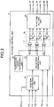
- FIG. 2 is a diagram of a configuration example of the voltage control unit 5.
- the voltage control unit 5 includes a position estimating unit 14 that estimates a magnetic pole position on the basis of the outputs Hu, Hv, and Hw of the magnetic-pole-position detecting unit 11 and generates the rotating speed signal FG, a waveform generating unit 15 that generates waveform outputs Vu*, Vv*, and Vw* respectively corresponding to a U phase, a V phase, and a W Phase as modulation waves on the basis of an estimated position, which is an estimation result by the position estimating unit 14, the rotating speed control signal Vsp, and the voltage phase ⁇ f, a triangular-wave generating unit 16 that generates a triangular wave as a carrier wave, a comparing unit 17 that compares the waveform outputs Vu*, Vv*, and Vw* generated by the waveform generating unit 15 and the triangular wave generated by the triangular-wave generating unit 16 and outputs High or Low signals respectively corresponding to the
- the voltage control unit 5 outputs the signals after the setting of the dead times in the dead-time setting unit 19 as PWM signals (UP, VP, WP, UN, VN, and WN) for controlling the voltage output unit 3 (the opening and closing units forming the voltage output unit 3) and causes the opening and closing sections 6a to 6f of the voltage output unit 3 to operate to drive the permanent magnet synchronous motor 7.
- PWM signals UP, VP, WP, UN, VN, and WN
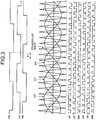
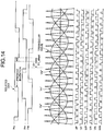
- FIG. 3 is a diagram of an example of input and output timings of the voltage control unit 5.
- the voltage control unit 5 sets a rising edge zero cross of the U-phase waveform output Vu* having a substantially sine wave shape in, for example, a position to which a phase equivalent to the voltage phase ⁇ f has advanced from a falling edge of Hu set as a reference, and generates the waveform outputs Vv* and Vw* of the V phase and the W phase having a phase difference of ⁇ 120° with respect to the U phase.
- the voltage control unit 5 compares the generated waveform outputs Vu*, Vv*, and Vw* with the triangular wave (the triangular wave generated by the triangular-wave generating unit 16). For example, when Vu* is larger than the triangular wave, the voltage control unit 5 outputs High as UP and outputs Low as UN. The voltage control unit 5 calculates outputs for the V phase and the W phase in the same manner.
- the waveform outputs Vu*, Vv*, and Vw* are the substantially sine waves.
- the voltage control unit 5 operates on the basis of the rotating speed control signal Vsp, the voltage advance angle ⁇ f, and the position signals Hu, Hv, and Hw. However, the voltage control unit 5 drives or does not drive the permanent magnet synchronous motor 7 according to only Vsp, and the voltage output of the voltage control unit 5 is as shown in FIG. 4 .
- a section of ⁇ 1> (0 to Vsp0) is a stopped state.
- Vsp an offset equivalent to Vsp0 is generated until the permanent magnet synchronous motor 7 actually starts driving after the motor driving circuit 1 starts operation, and the value of Vsp starts to increase.
- Vsp exceeds Vsp0, the rotor 9 of the permanent magnet synchronous motor 7 starts rotation and the value of the rotating speed signal FG output from the position estimating unit 14 fluctuates.
- a circuit that generates Vsp calculates the rotating speed of the rotor 9 on the basis of the rotating speed signal FG and controls Vsp to increase or decrease according to a difference between the calculated rotating speed and a target rotating speed to cause the rotor 9 to stably operate at the speed near the target rotating speed.
- FIG. 5 An optimum relation between the rotating speed control signal Vsp and the voltage advance angle ⁇ f in an apparatus, a load of which increases according to the rotating speed, is shown in FIG. 5 .
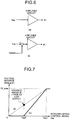
- FIG. 6 and FIG. 7 are diagrams of schematic configurations and schematic operations of the voltage-phase adjusting unit 12 (for convenience of explanation, referred to as "voltage-advance-angle-signal generating circuit") in the related art and this embodiment.
- FIG. 6 shows the schematic of the conventional voltage-advance-angle-signal generating circuit and (b) shows the schematic of the voltage-advance-angle-signal generating circuit (the voltage-phase adjusting unit 12) in this embodiment.
- FIG. 7 shows a generation operation for the voltage advance angle signal ( ⁇ f).
- (a) is the conventional operation and (b) is the operation in this embodiment.
- the permanent magnet synchronous motor 7 actually starts driving after Vsp exceeds Vsp0. Therefore, as shown in FIG. 7(a) , ⁇ f is not 0° at Vsp0 and a voltage advance angle greatly advances. Therefore, when the speed is low, deterioration in efficiency and an increase in noise are caused.
- the rotating speed control signal Vsp is amplified by the amplifier circuit after the offset Voffset equivalent to Vsp0, with which a voltage output is started, is subtracted from Vsp. Therefore, it is possible to set ⁇ f to 0° at Vsp0, so that it is made possible to suppress deterioration in efficiency and an increase in noise when the speed is low.
- the voltage advance angle ⁇ f can be continuously changed. Therefore, when the voltage advance angle changes stepwise as in Patent Literature 1, the likelihood of damage to the apparatus due to a current change and occurrence of unpleasant noise due to speed fluctuation is reduced. It is possible to perform an operation with improved reliability.
- FIG. 8 is a diagram of a circuit configuration example of the voltage-phase adjusting unit 12 and the offset generating unit 13 of the first embodiment.
- the voltage-phase adjusting unit 12 includes a differential amplifier circuit formed by an operational amplifier OP1, resistors R1 to R4, and capacitors C1 and C2.
- Voltage follower circuits formed by operational amplifiers OP2 and OP3 are respectively connected to two input terminals (V+in and V-in) of the differential amplifier circuit to reduce the influence due to the impedance at a connection destination.
- Vsp is input to the V+in terminal via the voltage follower circuit formed by the OP3.
- the offset generating unit 13 is connected to the V-in terminal via the voltage follower circuit formed by the OP2.
- the differential amplifier circuit of the voltage-phase adjusting unit 12 amplifies a difference between the V+in terminal and the V-in terminal with a factor determined by resistance values of the resistors R1 to R4 and outputs the difference as the voltage advance angle ⁇ f.
- the offset generating unit 13 is configured to divide the control power supply 10 (Vcc) by resistors R5 and R6 and outputs the control power supply 10. It is possible to inexpensively generate an offset with a necessary minimum configuration. When it is desired to highly accurately control the voltage advance angle ⁇ f, accuracy of the offset is required. Therefore, the offset can be generated using an apparatus such as a shunt regulator.
- ⁇ f is output at a voltage equal to or lower than about 1 volt even if a difference between V+in and V-in is, for example, near 0 because of a saturation voltage of the operational amplifier OP1.
- the offset generating unit 13 selects the offset Voffset taking the saturation voltage in to account. Consequently, it is possible to eliminate the influence of the saturation voltage.
- the voltage followers formed by the operational amplifiers OP2 and OP3 are used to reduce the influence of impedance.
- the voltage followers can be omitted to attain a cost reduction.
- the capacitors C1 and C2 are provided to set a cutoff frequency of a low-pass filter formed by R3 and R4, which are connected in parallel, to the frequency equal to or lower than the frequency of the permanent magnet synchronous motor to attain stability of the rotating speed.
- the value of the voltage phase ⁇ f is unstable and a maximum efficiency operation cannot be performed.
- the voltage advance angle ⁇ f is excessively increased, the permanent magnet synchronous motor 7 performs a flux-weakening operation, and a voltage necessary for rotation decreases. Therefore, even when the rotating speed control signal Vsp is small, the rotating speed of the permanent magnet synchronous motor 7 increases. Further, because a flowing current also increases, in the worst case, it is likely that the motor driving circuit 1 and the permanent magnet synchronous motor 7 are broken.
- a mechanism for limiting one or both of a lower limit and an upper limit of the voltage advance angle ⁇ f output by the voltage-phase adjusting unit 12 can be provided. Consequently, it is made possible to prevent breakage of the motor driving circuit 1 and the permanent magnet synchronous motor 7 and attain an improvement of the reliability.
- the function for the limitation of the voltage advance angle ⁇ f is often incorporated in an IC configuring the voltage control unit 5.
- the function implemented in the voltage control unit 5 it is possible to limit the voltage advance angle ⁇ f without preparing a special circuit outside. Therefore, it is possible to attain not only the improvement of the reliability but also a cost reduction.
- the voltage-phase adjusting unit 12 which generates the voltage advance angle ⁇ f for designating the relation between the triangular wave serving as a carrier wave and the waveforms (Vu*, Vv*, and Vw*) set as comparison target with the triangular wave, generates the voltage advance angle ⁇ f on the basis of the rotating speed control signal (Vsp) and the offset value (Voffset) generated by the offset generating unit 13.
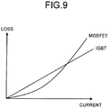
- the switching elements configuring the opening and closing units 6a to 6f can be changed from IGBTs (Insulated Gate bipolar Transistors) to MOSFETs (Metal-Oxide-Semiconductor Field-Effect Transistors).
- IGBTs Insulated Gate bipolar Transistors
- MOSFETs Metal-Oxide-Semiconductor Field-Effect Transistors
- FIG. 9 the MOSFET operates with a low loss in a low current region. Therefore, energy saving (high efficiency) can be realized by forming the opening and closing units 6a to 6f using the MOSFETs.
- heat generation also decreases, it is possible to attain small design of the entire apparatus through a reduction in the size of heat radiation fins.
- the reflux diodes configuring the opening and closing units 6a to 6f can be made by wide band gap semiconductor.
- a loss reducing effect can be obtained by using the MOSFET and the wide band gap semiconductor in a part (at least one) of the opening and closing units 6a to 6f.
- the voltage-phase adjusting unit 12 continuously increases the voltage advance angle ⁇ f according to the rotating speed. Therefore, by applying the motor driving circuit to a ventilation fan or the like, the load of which increases according to the speed, the ventilation fan is operated at an optimum voltage advance angle. Therefore, it is possible to attain a reduction in noise during the low speed. During the high speed, it is possible to reduce an electric current flowing to the permanent magnet synchronous motor 7 and the voltage output unit 3. Therefore, the effect explained above can be obtained. Further, it is possible to prevent a voltage advance angle from suddenly changing. As a result, it is possible to stably control the speed of the ventilation fan. It is possible to improve the reliability.
- the motor driving circuit 1 and the permanent magnet synchronous motor 7 are molded by mold resin 20. Consequently, the motor driving circuit 1 and the permanent magnet synchronous motor 7 are less easily affected by sand dust and water and the reliability is improved. Further, the dielectric strength of the permanent magnet synchronous motor 7 is improved.
- heat generation is intense because a large current flows to the motor driving circuit 1 and the permanent magnet synchronous motor 7.
- heat is radiated via the mold resin 20. Further, because a heat capacity increases, the motor driving circuit 1 and the permanent magnet synchronous motor 7 less easily generate heat, and it is possible to prevent thermal destruction of the motor driving circuit 1 due to the heat generation.
- FIG. 11 is a diagram of a configuration example of a motor driving circuit in a second embodiment.
- the offset generating unit 13 is removed from the motor driving circuit 1 in the first embodiment and the voltage-phase adjusting unit 12 is replaced with a voltage-phase adjusting unit 12a.
- the other components are the same as those in the first embodiment. Therefore, the components are denoted by the same reference numerals and signs and explanation of the components is omitted.
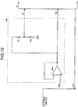
- FIG. 12 is a diagram of a circuit configuration example of the voltage-phase adjusting unit 12a in the second embodiment.
- the voltage-phase adjusting unit 12a is configured by an operational amplifier OP4 and resistors R7 and R8.
- a rotating speed control signal Vsp generated from an external circuit is input to the voltage control unit 5 and a voltage dividing circuit formed by the resistors R7 and R8 via a voltage follower circuit formed by the operational amplifier OP4.
- the voltage dividing circuit multiples the input rotating speed control signal Vsp with R8/(R7+R8) and outputs a value obtained as a result of the multiplication to the voltage control unit 5 as the voltage advance angle ⁇ f.
- the voltage advance angle ⁇ f is generated only by multiplying Vsp with R8/(R7+R8) using the voltage dividing circuit, as in the control by the conventional method shown in FIG. 7(a) , the voltage advance angle ⁇ f is made excessively large at low speed, and there is a concern about, for example, an increase in heat generation and noise due to a current increase. Therefore, in this embodiment, as shown in FIG. 13 , an attachment position of the magnetic-pole-position detecting unit 11 is rotated around the shaft 21. That is, the magnetic-pole-position detecting unit 11 is attached to a position different from the position in the first embodiment (see FIG. 10 ).
- Vsp is increased to be larger than Vsp0, a substantial advance angle can be continuously increased from 0.
- the effect same as the effect in the first embodiment can be obtained.
- the number of components of the voltage-phase adjusting unit 12a can be reduced to be smaller than the number of components of the voltage-phase adjusting unit 12 of the first embodiment.
- the magnetic-pole-position detecting unit 11 is changed only in the attachment position thereof. Therefore, it is possible to realize a motor driving circuit at low costs. Further, it is possible to reduce size and secure reliability through the reduction in the number of components and secure the reliability.
- the motor driving circuit according to the present invention is useful in driving the permanent magnet synchronous motor and is suitable for, in particular, motor driving circuits that drive fan motors of outdoor machines and indoor machines of an air conditioner and a heat pump water heater, a fan motor for ventilation, and the like.
Landscapes
- Engineering & Computer Science (AREA)
- Power Engineering (AREA)
- Control Of Motors That Do Not Use Commutators (AREA)
Applications Claiming Priority (1)
| Application Number | Priority Date | Filing Date | Title |
|---|---|---|---|
| PCT/JP2012/051827 WO2013111326A1 (ja) | 2012-01-27 | 2012-01-27 | モータ駆動回路および永久磁石同期モータ |
Publications (3)
| Publication Number | Publication Date |
|---|---|
| EP2808997A1 EP2808997A1 (en) | 2014-12-03 |
| EP2808997A4 EP2808997A4 (en) | 2016-03-23 |
| EP2808997B1 true EP2808997B1 (en) | 2017-11-29 |
Family
ID=48873089
Family Applications (1)
| Application Number | Title | Priority Date | Filing Date |
|---|---|---|---|
| EP12866656.7A Active EP2808997B1 (en) | 2012-01-27 | 2012-01-27 | Motor driving circuit and permanent magnet synchronous motor |
Country Status (5)
| Country | Link |
|---|---|
| US (1) | US9231507B2 (zh) |
| EP (1) | EP2808997B1 (zh) |
| JP (1) | JP5797781B2 (zh) |
| CN (1) | CN104054258B (zh) |
| WO (1) | WO2013111326A1 (zh) |
Families Citing this family (11)
| Publication number | Priority date | Publication date | Assignee | Title |
|---|---|---|---|---|
| WO2012086010A1 (ja) * | 2010-12-21 | 2012-06-28 | 三菱電機株式会社 | ヒートポンプ装置、ヒートポンプシステム及び三相インバータの制御方法 |
| JP6329504B2 (ja) * | 2015-03-17 | 2018-05-23 | ミネベアミツミ株式会社 | モータ駆動制御装置およびモータ駆動制御方法 |
| JP6324919B2 (ja) * | 2015-03-17 | 2018-05-16 | ミネベアミツミ株式会社 | モータ駆動制御装置及びその制御方法 |
| JP6374857B2 (ja) * | 2015-11-27 | 2018-08-15 | ミネベアミツミ株式会社 | モータ駆動制御装置 |
| JP6296566B2 (ja) * | 2015-11-27 | 2018-03-20 | ミネベアミツミ株式会社 | モータ駆動制御装置 |
| DE102016221459A1 (de) * | 2016-11-02 | 2018-05-03 | Robert Bosch Gmbh | Verfahren zur Bestimmung einer Drehwinkelposition einer Kurbelwelle einer Brennkraftmaschine |
| TW201910645A (zh) * | 2017-07-26 | 2019-03-16 | 茂達電子股份有限公司 | 風扇控制電路以及風扇控制方法 |
| CN108809165A (zh) * | 2018-06-29 | 2018-11-13 | 广东水利电力职业技术学院(广东省水利电力技工学校) | 一种交流伺服驱动器系统及控制方法 |
| US11425507B2 (en) | 2018-08-08 | 2022-08-23 | Graphaudio Inc. | High volume manufacturing of micro electrostatic transducers |
| JP7163223B2 (ja) * | 2019-03-14 | 2022-10-31 | 株式会社東芝 | 駆動装置、駆動システム、及び、電動機の駆動方法 |
| CN113581233B (zh) * | 2021-07-23 | 2022-06-17 | 石家庄国祥运输设备有限公司 | 一种轨道车辆空调通风机的控制方法 |
Family Cites Families (22)
| Publication number | Priority date | Publication date | Assignee | Title |
|---|---|---|---|---|
| US4546293A (en) * | 1982-08-24 | 1985-10-08 | Sundstrand Corporation | Motor control for a brushless DC motor |
| JP3360934B2 (ja) | 1994-06-07 | 2003-01-07 | 株式会社日立製作所 | ブラシレスモータの通電位相角制御装置 |
| DE10037972B4 (de) * | 1999-08-05 | 2005-09-15 | Sharp K.K. | Vorrichtung und Verfahren zur Elektromotorsteuerung |
| US6222333B1 (en) * | 1999-12-10 | 2001-04-24 | Texas Instruments Incorporated | DC brushless motor controller apparatus and method |
| JP3442024B2 (ja) * | 2000-02-29 | 2003-09-02 | 株式会社日立製作所 | モータ駆動回路及びモータ駆動方法、並びに半導体集積回路装置 |
| JP2002101683A (ja) | 2000-09-26 | 2002-04-05 | Nidec Shibaura Corp | ブラシレスdcモータの位相角制御方法 |
| US6694287B2 (en) * | 2001-08-30 | 2004-02-17 | Delphi Technologies, Inc. | Phase angle diagnostics for sinusoidal controlled electric machine |
| WO2003029503A2 (en) * | 2001-10-01 | 2003-04-10 | Delphi Technologies, Inc. | Method and apparatus for calibrating and initializing an electronically commutated electric machine |
| JP3713549B2 (ja) * | 2001-12-11 | 2005-11-09 | 日本電産シバウラ株式会社 | ブラシレス直流モータ |
| JP2003324985A (ja) | 2002-04-26 | 2003-11-14 | Toyoda Mach Works Ltd | モータ制御装置 |
| JP2004180399A (ja) * | 2002-11-26 | 2004-06-24 | Murata Mach Ltd | 糸条巻取機におけるモータ駆動方法 |
| JP4671331B2 (ja) | 2004-02-25 | 2011-04-13 | ローム株式会社 | 位相調整回路、モータ駆動制御回路、及びモータ装置 |
| JP4422567B2 (ja) * | 2004-06-30 | 2010-02-24 | 株式会社日立製作所 | モータ駆動装置,電動アクチュエータおよび電動パワーステアリング装置 |
| US7075267B1 (en) * | 2004-12-29 | 2006-07-11 | Prolific Technology Inc. | Space vector-based current controlled PWM inverter for motor drives |
| JP2007275827A (ja) * | 2006-04-10 | 2007-10-25 | Tsubaki Emerson Co | 細断機のブラシレスdcモータの制御方法、及び細断機のブラシレスdcモータの制御装置 |
| JP2008005632A (ja) * | 2006-06-22 | 2008-01-10 | Matsushita Electric Ind Co Ltd | モータ駆動装置及びモータ駆動方法並びにディスク駆動装置 |
| JP2009303287A (ja) * | 2008-06-10 | 2009-12-24 | Nidec Shibaura Corp | モータ制御装置 |
| CN101615876B (zh) * | 2009-08-07 | 2011-07-27 | 北京和利时电机技术有限公司 | 一种隐极式永磁同步电机的调速控制系统和方法 |
| JP2011045217A (ja) * | 2009-08-24 | 2011-03-03 | Ricoh Co Ltd | ブラシレスモータ駆動装置 |
| JP2011114995A (ja) | 2009-11-30 | 2011-06-09 | Nidec Shibaura Corp | モータ用駆動回路及びそれを備えたモータ |
| JP5484926B2 (ja) * | 2010-01-18 | 2014-05-07 | 三菱重工業株式会社 | 絶縁劣化検知装置及び車載高電圧系統 |
| WO2011111175A1 (ja) | 2010-03-09 | 2011-09-15 | 三菱電機株式会社 | パワー半導体モジュール、電力変換装置および鉄道車両 |
-
2012
- 2012-01-27 JP JP2013555081A patent/JP5797781B2/ja active Active
- 2012-01-27 US US14/369,733 patent/US9231507B2/en not_active Expired - Fee Related
- 2012-01-27 EP EP12866656.7A patent/EP2808997B1/en active Active
- 2012-01-27 WO PCT/JP2012/051827 patent/WO2013111326A1/ja active Application Filing
- 2012-01-27 CN CN201280067341.XA patent/CN104054258B/zh not_active Expired - Fee Related
Non-Patent Citations (1)
| Title |
|---|
| None * |
Also Published As
| Publication number | Publication date |
|---|---|
| WO2013111326A1 (ja) | 2013-08-01 |
| EP2808997A4 (en) | 2016-03-23 |
| JP5797781B2 (ja) | 2015-10-21 |
| US20150002061A1 (en) | 2015-01-01 |
| CN104054258A (zh) | 2014-09-17 |
| EP2808997A1 (en) | 2014-12-03 |
| US9231507B2 (en) | 2016-01-05 |
| CN104054258B (zh) | 2016-09-28 |
| JPWO2013111326A1 (ja) | 2015-05-11 |
Similar Documents
| Publication | Publication Date | Title |
|---|---|---|
| EP2808997B1 (en) | Motor driving circuit and permanent magnet synchronous motor | |
| US10348226B2 (en) | Device and control method for driving sensorless BLDC motor | |
| US7321210B2 (en) | Sensorless brushless direct current motor drive using pulse width modulation speed control at motor frequency | |
| US20120081064A1 (en) | Control of an electrical machine | |
| US11165381B2 (en) | Speed contant control and power constant control of a permanent magnet synchronous motor | |
| WO2018138807A1 (ja) | モータ駆動装置、電動送風機、電気掃除機及びハンドドライヤ | |
| TW201526523A (zh) | 馬達之驅動裝置、驅動方法及冷卻裝置、電子機器 | |
| CN111742481B (zh) | 电力变换装置 | |
| JP3353586B2 (ja) | ブラシレスdcモータの駆動装置 | |
| JP6462821B2 (ja) | モータ駆動装置 | |
| CN108075690B (zh) | 马达驱动系统及其运转回复方法 | |
| JP6301270B2 (ja) | モータ駆動装置 | |
| JP2005229736A (ja) | 電動機駆動装置およびそれを用いた空気調和機 | |
| Lai et al. | Back-EMF detection technique of brushless DC motor drives for wide range control | |
| WO2020230235A1 (ja) | 負荷駆動装置、空気調和機及び負荷駆動装置の運転方法 | |
| US11557998B2 (en) | Open loop duty control with automatic field orientation for a permanent magnet AC (PMAC) motor | |
| KR102612830B1 (ko) | 전력변환장치 | |
| US11971200B2 (en) | Heat pump apparatus with compressor heating control | |
| US11146195B2 (en) | Fail-safe function for a permanent magnet synchronous motor | |
| US20230421087A1 (en) | Reduced motor magnetic losses via reduction of temporal harmonics by control of dc link voltage | |
| CN110620459B (zh) | 用于操作bldc电动机的驱动电路 | |
| CN116247997A (zh) | 在电压控制模式下操作的永磁同步电机的负载自适应弱磁 |
Legal Events
| Date | Code | Title | Description |
|---|---|---|---|
| PUAI | Public reference made under article 153(3) epc to a published international application that has entered the european phase |
Free format text: ORIGINAL CODE: 0009012 |
|
| 17P | Request for examination filed |
Effective date: 20140820 |
|
| AK | Designated contracting states |
Kind code of ref document: A1 Designated state(s): AL AT BE BG CH CY CZ DE DK EE ES FI FR GB GR HR HU IE IS IT LI LT LU LV MC MK MT NL NO PL PT RO RS SE SI SK SM TR |
|
| DAX | Request for extension of the european patent (deleted) | ||
| RA4 | Supplementary search report drawn up and despatched (corrected) |
Effective date: 20160222 |
|
| RIC1 | Information provided on ipc code assigned before grant |
Ipc: H02P 6/15 20160101ALI20160216BHEP Ipc: H02P 6/20 20160101ALI20160216BHEP Ipc: H02P 21/00 20160101AFI20160216BHEP Ipc: H02P 27/04 20060101ALI20160216BHEP |
|
| GRAP | Despatch of communication of intention to grant a patent |
Free format text: ORIGINAL CODE: EPIDOSNIGR1 |
|
| RIC1 | Information provided on ipc code assigned before grant |
Ipc: H02P 21/00 20160101AFI20170601BHEP Ipc: H02P 27/04 20160101ALI20170601BHEP Ipc: H02P 6/15 20160101ALI20170601BHEP Ipc: H02P 6/20 20160101ALI20170601BHEP |
|
| INTG | Intention to grant announced |
Effective date: 20170621 |
|
| GRAS | Grant fee paid |
Free format text: ORIGINAL CODE: EPIDOSNIGR3 |
|
| GRAA | (expected) grant |
Free format text: ORIGINAL CODE: 0009210 |
|
| AK | Designated contracting states |
Kind code of ref document: B1 Designated state(s): AL AT BE BG CH CY CZ DE DK EE ES FI FR GB GR HR HU IE IS IT LI LT LU LV MC MK MT NL NO PL PT RO RS SE SI SK SM TR |
|
| REG | Reference to a national code |
Ref country code: CH Ref legal event code: EP |
|
| REG | Reference to a national code |
Ref country code: AT Ref legal event code: REF Ref document number: 951261 Country of ref document: AT Kind code of ref document: T Effective date: 20171215 |
|
| REG | Reference to a national code |
Ref country code: IE Ref legal event code: FG4D |
|
| REG | Reference to a national code |
Ref country code: DE Ref legal event code: R096 Ref document number: 602012040458 Country of ref document: DE |
|
| REG | Reference to a national code |
Ref country code: FR Ref legal event code: PLFP Year of fee payment: 7 |
|
| REG | Reference to a national code |
Ref country code: NL Ref legal event code: MP Effective date: 20171129 |
|
| REG | Reference to a national code |
Ref country code: LT Ref legal event code: MG4D |
|
| REG | Reference to a national code |
Ref country code: AT Ref legal event code: MK05 Ref document number: 951261 Country of ref document: AT Kind code of ref document: T Effective date: 20171129 |
|
| PG25 | Lapsed in a contracting state [announced via postgrant information from national office to epo] |
Ref country code: SE Free format text: LAPSE BECAUSE OF FAILURE TO SUBMIT A TRANSLATION OF THE DESCRIPTION OR TO PAY THE FEE WITHIN THE PRESCRIBED TIME-LIMIT Effective date: 20171129 Ref country code: NO Free format text: LAPSE BECAUSE OF FAILURE TO SUBMIT A TRANSLATION OF THE DESCRIPTION OR TO PAY THE FEE WITHIN THE PRESCRIBED TIME-LIMIT Effective date: 20180228 Ref country code: FI Free format text: LAPSE BECAUSE OF FAILURE TO SUBMIT A TRANSLATION OF THE DESCRIPTION OR TO PAY THE FEE WITHIN THE PRESCRIBED TIME-LIMIT Effective date: 20171129 Ref country code: ES Free format text: LAPSE BECAUSE OF FAILURE TO SUBMIT A TRANSLATION OF THE DESCRIPTION OR TO PAY THE FEE WITHIN THE PRESCRIBED TIME-LIMIT Effective date: 20171129 Ref country code: LT Free format text: LAPSE BECAUSE OF FAILURE TO SUBMIT A TRANSLATION OF THE DESCRIPTION OR TO PAY THE FEE WITHIN THE PRESCRIBED TIME-LIMIT Effective date: 20171129 |
|
| PG25 | Lapsed in a contracting state [announced via postgrant information from national office to epo] |
Ref country code: GR Free format text: LAPSE BECAUSE OF FAILURE TO SUBMIT A TRANSLATION OF THE DESCRIPTION OR TO PAY THE FEE WITHIN THE PRESCRIBED TIME-LIMIT Effective date: 20180301 Ref country code: HR Free format text: LAPSE BECAUSE OF FAILURE TO SUBMIT A TRANSLATION OF THE DESCRIPTION OR TO PAY THE FEE WITHIN THE PRESCRIBED TIME-LIMIT Effective date: 20171129 Ref country code: AT Free format text: LAPSE BECAUSE OF FAILURE TO SUBMIT A TRANSLATION OF THE DESCRIPTION OR TO PAY THE FEE WITHIN THE PRESCRIBED TIME-LIMIT Effective date: 20171129 Ref country code: BG Free format text: LAPSE BECAUSE OF FAILURE TO SUBMIT A TRANSLATION OF THE DESCRIPTION OR TO PAY THE FEE WITHIN THE PRESCRIBED TIME-LIMIT Effective date: 20180228 Ref country code: RS Free format text: LAPSE BECAUSE OF FAILURE TO SUBMIT A TRANSLATION OF THE DESCRIPTION OR TO PAY THE FEE WITHIN THE PRESCRIBED TIME-LIMIT Effective date: 20171129 Ref country code: LV Free format text: LAPSE BECAUSE OF FAILURE TO SUBMIT A TRANSLATION OF THE DESCRIPTION OR TO PAY THE FEE WITHIN THE PRESCRIBED TIME-LIMIT Effective date: 20171129 |
|
| PG25 | Lapsed in a contracting state [announced via postgrant information from national office to epo] |
Ref country code: NL Free format text: LAPSE BECAUSE OF FAILURE TO SUBMIT A TRANSLATION OF THE DESCRIPTION OR TO PAY THE FEE WITHIN THE PRESCRIBED TIME-LIMIT Effective date: 20171129 |
|
| PG25 | Lapsed in a contracting state [announced via postgrant information from national office to epo] |
Ref country code: CY Free format text: LAPSE BECAUSE OF FAILURE TO SUBMIT A TRANSLATION OF THE DESCRIPTION OR TO PAY THE FEE WITHIN THE PRESCRIBED TIME-LIMIT Effective date: 20171129 Ref country code: EE Free format text: LAPSE BECAUSE OF FAILURE TO SUBMIT A TRANSLATION OF THE DESCRIPTION OR TO PAY THE FEE WITHIN THE PRESCRIBED TIME-LIMIT Effective date: 20171129 Ref country code: DK Free format text: LAPSE BECAUSE OF FAILURE TO SUBMIT A TRANSLATION OF THE DESCRIPTION OR TO PAY THE FEE WITHIN THE PRESCRIBED TIME-LIMIT Effective date: 20171129 Ref country code: SK Free format text: LAPSE BECAUSE OF FAILURE TO SUBMIT A TRANSLATION OF THE DESCRIPTION OR TO PAY THE FEE WITHIN THE PRESCRIBED TIME-LIMIT Effective date: 20171129 Ref country code: CZ Free format text: LAPSE BECAUSE OF FAILURE TO SUBMIT A TRANSLATION OF THE DESCRIPTION OR TO PAY THE FEE WITHIN THE PRESCRIBED TIME-LIMIT Effective date: 20171129 |
|
| REG | Reference to a national code |
Ref country code: DE Ref legal event code: R097 Ref document number: 602012040458 Country of ref document: DE |
|
| PG25 | Lapsed in a contracting state [announced via postgrant information from national office to epo] |
Ref country code: IT Free format text: LAPSE BECAUSE OF FAILURE TO SUBMIT A TRANSLATION OF THE DESCRIPTION OR TO PAY THE FEE WITHIN THE PRESCRIBED TIME-LIMIT Effective date: 20171129 Ref country code: RO Free format text: LAPSE BECAUSE OF FAILURE TO SUBMIT A TRANSLATION OF THE DESCRIPTION OR TO PAY THE FEE WITHIN THE PRESCRIBED TIME-LIMIT Effective date: 20171129 Ref country code: SM Free format text: LAPSE BECAUSE OF FAILURE TO SUBMIT A TRANSLATION OF THE DESCRIPTION OR TO PAY THE FEE WITHIN THE PRESCRIBED TIME-LIMIT Effective date: 20171129 Ref country code: PL Free format text: LAPSE BECAUSE OF FAILURE TO SUBMIT A TRANSLATION OF THE DESCRIPTION OR TO PAY THE FEE WITHIN THE PRESCRIBED TIME-LIMIT Effective date: 20171129 |
|
| REG | Reference to a national code |
Ref country code: CH Ref legal event code: PL |
|
| PLBE | No opposition filed within time limit |
Free format text: ORIGINAL CODE: 0009261 |
|
| STAA | Information on the status of an ep patent application or granted ep patent |
Free format text: STATUS: NO OPPOSITION FILED WITHIN TIME LIMIT |
|
| PG25 | Lapsed in a contracting state [announced via postgrant information from national office to epo] |
Ref country code: LU Free format text: LAPSE BECAUSE OF NON-PAYMENT OF DUE FEES Effective date: 20180127 |
|
| REG | Reference to a national code |
Ref country code: IE Ref legal event code: MM4A |
|
| 26N | No opposition filed |
Effective date: 20180830 |
|
| REG | Reference to a national code |
Ref country code: BE Ref legal event code: MM Effective date: 20180131 |
|
| PG25 | Lapsed in a contracting state [announced via postgrant information from national office to epo] |
Ref country code: BE Free format text: LAPSE BECAUSE OF NON-PAYMENT OF DUE FEES Effective date: 20180131 Ref country code: LI Free format text: LAPSE BECAUSE OF NON-PAYMENT OF DUE FEES Effective date: 20180131 Ref country code: SI Free format text: LAPSE BECAUSE OF FAILURE TO SUBMIT A TRANSLATION OF THE DESCRIPTION OR TO PAY THE FEE WITHIN THE PRESCRIBED TIME-LIMIT Effective date: 20171129 Ref country code: CH Free format text: LAPSE BECAUSE OF NON-PAYMENT OF DUE FEES Effective date: 20180131 |
|
| PG25 | Lapsed in a contracting state [announced via postgrant information from national office to epo] |
Ref country code: IE Free format text: LAPSE BECAUSE OF NON-PAYMENT OF DUE FEES Effective date: 20180127 |
|
| PG25 | Lapsed in a contracting state [announced via postgrant information from national office to epo] |
Ref country code: MC Free format text: LAPSE BECAUSE OF FAILURE TO SUBMIT A TRANSLATION OF THE DESCRIPTION OR TO PAY THE FEE WITHIN THE PRESCRIBED TIME-LIMIT Effective date: 20171129 |
|
| PG25 | Lapsed in a contracting state [announced via postgrant information from national office to epo] |
Ref country code: MT Free format text: LAPSE BECAUSE OF NON-PAYMENT OF DUE FEES Effective date: 20180127 |
|
| PG25 | Lapsed in a contracting state [announced via postgrant information from national office to epo] |
Ref country code: TR Free format text: LAPSE BECAUSE OF FAILURE TO SUBMIT A TRANSLATION OF THE DESCRIPTION OR TO PAY THE FEE WITHIN THE PRESCRIBED TIME-LIMIT Effective date: 20171129 |
|
| PG25 | Lapsed in a contracting state [announced via postgrant information from national office to epo] |
Ref country code: HU Free format text: LAPSE BECAUSE OF FAILURE TO SUBMIT A TRANSLATION OF THE DESCRIPTION OR TO PAY THE FEE WITHIN THE PRESCRIBED TIME-LIMIT; INVALID AB INITIO Effective date: 20120127 Ref country code: PT Free format text: LAPSE BECAUSE OF FAILURE TO SUBMIT A TRANSLATION OF THE DESCRIPTION OR TO PAY THE FEE WITHIN THE PRESCRIBED TIME-LIMIT Effective date: 20171129 |
|
| PG25 | Lapsed in a contracting state [announced via postgrant information from national office to epo] |
Ref country code: MK Free format text: LAPSE BECAUSE OF NON-PAYMENT OF DUE FEES Effective date: 20171129 |
|
| PG25 | Lapsed in a contracting state [announced via postgrant information from national office to epo] |
Ref country code: AL Free format text: LAPSE BECAUSE OF FAILURE TO SUBMIT A TRANSLATION OF THE DESCRIPTION OR TO PAY THE FEE WITHIN THE PRESCRIBED TIME-LIMIT Effective date: 20171129 Ref country code: IS Free format text: LAPSE BECAUSE OF FAILURE TO SUBMIT A TRANSLATION OF THE DESCRIPTION OR TO PAY THE FEE WITHIN THE PRESCRIBED TIME-LIMIT Effective date: 20180329 |
|
| REG | Reference to a national code |
Ref country code: GB Ref legal event code: 746 Effective date: 20200819 |
|
| REG | Reference to a national code |
Ref country code: DE Ref legal event code: R084 Ref document number: 602012040458 Country of ref document: DE |
|
| PGFP | Annual fee paid to national office [announced via postgrant information from national office to epo] |
Ref country code: GB Payment date: 20221208 Year of fee payment: 12 Ref country code: FR Payment date: 20221208 Year of fee payment: 12 |
|
| PGFP | Annual fee paid to national office [announced via postgrant information from national office to epo] |
Ref country code: DE Payment date: 20221130 Year of fee payment: 12 |
|
| P01 | Opt-out of the competence of the unified patent court (upc) registered |
Effective date: 20230512 |