EP2802412B1 - Transparent photocatalyst coating - Google Patents
Transparent photocatalyst coating Download PDFInfo
- Publication number
- EP2802412B1 EP2802412B1 EP13735689.5A EP13735689A EP2802412B1 EP 2802412 B1 EP2802412 B1 EP 2802412B1 EP 13735689 A EP13735689 A EP 13735689A EP 2802412 B1 EP2802412 B1 EP 2802412B1
- Authority
- EP
- European Patent Office
- Prior art keywords
- photocatalyst
- ceo
- substrate
- photocatalytic
- molar
- Prior art date
- Legal status (The legal status is an assumption and is not a legal conclusion. Google has not performed a legal analysis and makes no representation as to the accuracy of the status listed.)
- Active
Links
Images




Classifications
-
- B—PERFORMING OPERATIONS; TRANSPORTING
- B01—PHYSICAL OR CHEMICAL PROCESSES OR APPARATUS IN GENERAL
- B01J—CHEMICAL OR PHYSICAL PROCESSES, e.g. CATALYSIS OR COLLOID CHEMISTRY; THEIR RELEVANT APPARATUS
- B01J27/00—Catalysts comprising the elements or compounds of halogens, sulfur, selenium, tellurium, phosphorus or nitrogen; Catalysts comprising carbon compounds
- B01J27/24—Nitrogen compounds
-
- B—PERFORMING OPERATIONS; TRANSPORTING
- B01—PHYSICAL OR CHEMICAL PROCESSES OR APPARATUS IN GENERAL
- B01J—CHEMICAL OR PHYSICAL PROCESSES, e.g. CATALYSIS OR COLLOID CHEMISTRY; THEIR RELEVANT APPARATUS
- B01J23/00—Catalysts comprising metals or metal oxides or hydroxides, not provided for in group B01J21/00
- B01J23/16—Catalysts comprising metals or metal oxides or hydroxides, not provided for in group B01J21/00 of arsenic, antimony, bismuth, vanadium, niobium, tantalum, polonium, chromium, molybdenum, tungsten, manganese, technetium or rhenium
- B01J23/24—Chromium, molybdenum or tungsten
- B01J23/30—Tungsten
-
- B—PERFORMING OPERATIONS; TRANSPORTING
- B01—PHYSICAL OR CHEMICAL PROCESSES OR APPARATUS IN GENERAL
- B01J—CHEMICAL OR PHYSICAL PROCESSES, e.g. CATALYSIS OR COLLOID CHEMISTRY; THEIR RELEVANT APPARATUS
- B01J35/00—Catalysts, in general, characterised by their form or physical properties
- B01J35/19—Catalysts containing parts with different compositions
-
- B—PERFORMING OPERATIONS; TRANSPORTING
- B01—PHYSICAL OR CHEMICAL PROCESSES OR APPARATUS IN GENERAL
- B01J—CHEMICAL OR PHYSICAL PROCESSES, e.g. CATALYSIS OR COLLOID CHEMISTRY; THEIR RELEVANT APPARATUS
- B01J35/00—Catalysts, in general, characterised by their form or physical properties
- B01J35/30—Catalysts, in general, characterised by their form or physical properties characterised by their physical properties
- B01J35/39—Photocatalytic properties
-
- B—PERFORMING OPERATIONS; TRANSPORTING
- B01—PHYSICAL OR CHEMICAL PROCESSES OR APPARATUS IN GENERAL
- B01J—CHEMICAL OR PHYSICAL PROCESSES, e.g. CATALYSIS OR COLLOID CHEMISTRY; THEIR RELEVANT APPARATUS
- B01J35/00—Catalysts, in general, characterised by their form or physical properties
- B01J35/40—Catalysts, in general, characterised by their form or physical properties characterised by dimensions, e.g. grain size
-
- B—PERFORMING OPERATIONS; TRANSPORTING
- B01—PHYSICAL OR CHEMICAL PROCESSES OR APPARATUS IN GENERAL
- B01J—CHEMICAL OR PHYSICAL PROCESSES, e.g. CATALYSIS OR COLLOID CHEMISTRY; THEIR RELEVANT APPARATUS
- B01J37/00—Processes, in general, for preparing catalysts; Processes, in general, for activation of catalysts
- B01J37/0009—Use of binding agents; Moulding; Pressing; Powdering; Granulating; Addition of materials ameliorating the mechanical properties of the product catalyst
- B01J37/0027—Powdering
- B01J37/0036—Grinding
-
- B—PERFORMING OPERATIONS; TRANSPORTING
- B01—PHYSICAL OR CHEMICAL PROCESSES OR APPARATUS IN GENERAL
- B01J—CHEMICAL OR PHYSICAL PROCESSES, e.g. CATALYSIS OR COLLOID CHEMISTRY; THEIR RELEVANT APPARATUS
- B01J37/00—Processes, in general, for preparing catalysts; Processes, in general, for activation of catalysts
- B01J37/02—Impregnation, coating or precipitation
- B01J37/0201—Impregnation
- B01J37/0211—Impregnation using a colloidal suspension
-
- B—PERFORMING OPERATIONS; TRANSPORTING
- B01—PHYSICAL OR CHEMICAL PROCESSES OR APPARATUS IN GENERAL
- B01J—CHEMICAL OR PHYSICAL PROCESSES, e.g. CATALYSIS OR COLLOID CHEMISTRY; THEIR RELEVANT APPARATUS
- B01J37/00—Processes, in general, for preparing catalysts; Processes, in general, for activation of catalysts
- B01J37/04—Mixing
-
- B—PERFORMING OPERATIONS; TRANSPORTING
- B01—PHYSICAL OR CHEMICAL PROCESSES OR APPARATUS IN GENERAL
- B01J—CHEMICAL OR PHYSICAL PROCESSES, e.g. CATALYSIS OR COLLOID CHEMISTRY; THEIR RELEVANT APPARATUS
- B01J21/00—Catalysts comprising the elements, oxides, or hydroxides of magnesium, boron, aluminium, carbon, silicon, titanium, zirconium, or hafnium
- B01J21/06—Silicon, titanium, zirconium or hafnium; Oxides or hydroxides thereof
- B01J21/063—Titanium; Oxides or hydroxides thereof
-
- B—PERFORMING OPERATIONS; TRANSPORTING
- B01—PHYSICAL OR CHEMICAL PROCESSES OR APPARATUS IN GENERAL
- B01J—CHEMICAL OR PHYSICAL PROCESSES, e.g. CATALYSIS OR COLLOID CHEMISTRY; THEIR RELEVANT APPARATUS
- B01J23/00—Catalysts comprising metals or metal oxides or hydroxides, not provided for in group B01J21/00
- B01J23/02—Catalysts comprising metals or metal oxides or hydroxides, not provided for in group B01J21/00 of the alkali- or alkaline earth metals or beryllium
-
- B—PERFORMING OPERATIONS; TRANSPORTING
- B01—PHYSICAL OR CHEMICAL PROCESSES OR APPARATUS IN GENERAL
- B01J—CHEMICAL OR PHYSICAL PROCESSES, e.g. CATALYSIS OR COLLOID CHEMISTRY; THEIR RELEVANT APPARATUS
- B01J23/00—Catalysts comprising metals or metal oxides or hydroxides, not provided for in group B01J21/00
- B01J23/08—Catalysts comprising metals or metal oxides or hydroxides, not provided for in group B01J21/00 of gallium, indium or thallium
-
- B—PERFORMING OPERATIONS; TRANSPORTING
- B01—PHYSICAL OR CHEMICAL PROCESSES OR APPARATUS IN GENERAL
- B01J—CHEMICAL OR PHYSICAL PROCESSES, e.g. CATALYSIS OR COLLOID CHEMISTRY; THEIR RELEVANT APPARATUS
- B01J23/00—Catalysts comprising metals or metal oxides or hydroxides, not provided for in group B01J21/00
- B01J23/10—Catalysts comprising metals or metal oxides or hydroxides, not provided for in group B01J21/00 of rare earths
-
- B—PERFORMING OPERATIONS; TRANSPORTING
- B01—PHYSICAL OR CHEMICAL PROCESSES OR APPARATUS IN GENERAL
- B01J—CHEMICAL OR PHYSICAL PROCESSES, e.g. CATALYSIS OR COLLOID CHEMISTRY; THEIR RELEVANT APPARATUS
- B01J23/00—Catalysts comprising metals or metal oxides or hydroxides, not provided for in group B01J21/00
- B01J23/14—Catalysts comprising metals or metal oxides or hydroxides, not provided for in group B01J21/00 of germanium, tin or lead
-
- B—PERFORMING OPERATIONS; TRANSPORTING
- B01—PHYSICAL OR CHEMICAL PROCESSES OR APPARATUS IN GENERAL
- B01J—CHEMICAL OR PHYSICAL PROCESSES, e.g. CATALYSIS OR COLLOID CHEMISTRY; THEIR RELEVANT APPARATUS
- B01J23/00—Catalysts comprising metals or metal oxides or hydroxides, not provided for in group B01J21/00
- B01J23/16—Catalysts comprising metals or metal oxides or hydroxides, not provided for in group B01J21/00 of arsenic, antimony, bismuth, vanadium, niobium, tantalum, polonium, chromium, molybdenum, tungsten, manganese, technetium or rhenium
-
- B—PERFORMING OPERATIONS; TRANSPORTING
- B01—PHYSICAL OR CHEMICAL PROCESSES OR APPARATUS IN GENERAL
- B01J—CHEMICAL OR PHYSICAL PROCESSES, e.g. CATALYSIS OR COLLOID CHEMISTRY; THEIR RELEVANT APPARATUS
- B01J23/00—Catalysts comprising metals or metal oxides or hydroxides, not provided for in group B01J21/00
- B01J23/16—Catalysts comprising metals or metal oxides or hydroxides, not provided for in group B01J21/00 of arsenic, antimony, bismuth, vanadium, niobium, tantalum, polonium, chromium, molybdenum, tungsten, manganese, technetium or rhenium
- B01J23/20—Vanadium, niobium or tantalum
-
- B—PERFORMING OPERATIONS; TRANSPORTING
- B01—PHYSICAL OR CHEMICAL PROCESSES OR APPARATUS IN GENERAL
- B01J—CHEMICAL OR PHYSICAL PROCESSES, e.g. CATALYSIS OR COLLOID CHEMISTRY; THEIR RELEVANT APPARATUS
- B01J27/00—Catalysts comprising the elements or compounds of halogens, sulfur, selenium, tellurium, phosphorus or nitrogen; Catalysts comprising carbon compounds
- B01J27/20—Carbon compounds
- B01J27/22—Carbides
Definitions
- Visible-light activated photocatalysts can be deployed for self-cleaning, air and water purification and many other interesting applications usually without any post-deployment non-renewable energy costs. This is because the photocatalysts are able to decompose pollutants (like dyes, volatile organic compounds and NO x ) using available ambient light like solar radiation or indoor and outdoor lighting. With the anticipated rapid adoption of UV-free indoor lighting (like LEDs and OLEDs), it is imperative to find ways to deploy visible-light activated photocatalysts in indoor applications for instance in cleaning room air in domestic, public and commercial spaces especially in confined spaces like aircrafts, public buildings, etc. Moreover, additional applications for antibacterial surfaces and self-cleaning materials can have wide applicability in the food service, transportation, health care and hospitality sectors.
- photocatalytic coatings exhibit low photocatalytic activity, primarily due to low inherent activity of the base photocatalyst material as well as their incompatibility with the often used binders. Thus, there is a need for photocatalytic coatings and/or layers that exhibit desired photocatalytic levels and transparency.
- EP 2,248,586 A1 discloses a visible light responsive photocatalyst powder having organic gas decomposition performance that responds nonlinearly to an amount of irradiated light under visible light in an illuminance range of not less than 200 lx nor more than 2500 lx.
- the visible light responsive photocatalyst powder has a gas decomposition rate of 20% or more, for example, when visible light having only a wavelength of not less than 380 nm and an illuminance of 2500 lx is irradiated, the gas decomposition rate (%) being set as a value calculated based on [formula: (A - B) / A x 100], where A represents a gas concentration before light irradiation and B represents a gas concentration when not less than 15 minutes have elapsed from the light irradiation and, at the same time, the gas concentration is stable, the gas concentrations being measured while allowing an acetaldehyde gas having an initial concentration of 10 ppm to flow into a flow-type apparatus in which 0.2 g of a sample is placed.
- Photocatalytic compositions that include a photocatalyst and a co-catalyst may be useful for a variety of photocatalytic applications. Additionally, a co-catalyst may improve the photocatalytic activity of a photocatalyst, so that combination of a photocatalyst and a co-catalyst is more active than a photocatalyst alone. Furthermore, incorporation of photocatalytic material co-catalysts into photocatalytic coatings may help to improve the transparency and photocatalytic activity of the coating material.
- the photocatalytic composition according to the present invention is as defined in claim 1.
- a photocatalyst includes any material that can activate or change the rate of a chemical reaction as a result of exposure to light, such as ultraviolet or visible light.
- photocatalyst material may be an inorganic solid, such as a solid inorganic semiconductor, that absorbs ultraviolet or visible light.
- photocatalysis may be due to reactive species (able to perform reduction and oxidation) being formed on the surface of the photocatalyst from the electron-hole pairs generated in the bulk of the photocatalyst by said absorption of electromagnetic radiation.
- the photocatalyst has a conduction with an energy of about 1 eV to about 0 eV, about 0 eV to about -1 eV, or about -1 eV to about -2 eV, as compared to the normal hydrogen electrode.
- Some photocatalyst may have a valence band with energy of about 3 eV to about 3.5 eV, about 2.5 eV to about 3 eV, or about 2 eV to about 3.5 eV, or about 3.5 eV to about 5.0 eV as compared to the normal hydrogen electrode.
- a visible light photocatalyst includes a photocatalyst which is activated by visible light, e.g.
- Visible light photocatalysts can also be activated by UV light below 380 nm in wavelength in addition to visible wavelengths.
- Some visible light photocatalyst may have a band gap that corresponds to light in the visible range, such as a band gap greater than about 1.5 eV, less than about 3.5 eV, about 1.5 eV to about 3.5 eV, about 1.7 eV to about 3.3 eV, or 1.77 eV to 3.27 eV.
- Some photocatalyst may have a band gap of about 1.2 eV to about 6.2 eV, about 1.2 eV to about 1.5 eV, or about 3.5 eV to about 6.2 electron eV.
- the photocatalyst is a tungsten oxide including a tungsten oxide having a +1, +2, +3, +4, +5, +6, +7, or +8 oxidation state or formal charge, or an average oxidation state or formal charge of about +1 to about +8, about +4 to about +8, about +6 to about +8, or about +1 to about +4.
- the tungsten oxide can be WO 3 .
- the tungsten oxide can be nanopowders, nanoparticles, and or layers comprising the same.
- the photocatalyst material is at least about 0.01 molar % and less than 100 molar % of the composition. In some embodiments, the photocatalyst material is about 20 molar % to about 80 molar %, about 30 molar % to about 70 molar %, about 40 molar % to about 60 molar %, or about 50 molar % of the composition.
- WO 3 compounds e.g., nanopowders
- thermal plasma direct current and including radio frequency inductively-coupled plasma (RF-ICP)
- RF-ICP radio frequency inductively-coupled plasma
- solvothermal solid state reaction
- pyrolysis pyrolysis
- combustion pyrolysis
- Radio frequency inductively-coupled plasma e.g. thermal
- radio frequency inductively-coupled plasma processes are preferred.
- a liquid dispersion of ammonium metatungstate in water (5-20 wt% solid in water) can be sprayed into the plasma volume using a two-fluid atomizer.
- the precursor can be present to about 20 wt% solid in water.
- the plasma can be operated at about 25 kW plate power with argon, nitrogen and/or oxygen gases.
- the particles formed from the condensed vapor from the plasma can then be collected on filters.
- the particle surface areas range as measured using BET from about 1 m 2 /g to about 500 m 2 /g, about 15 m 2 /g to 30 m 2 /g, or about 20 m 2 /g.
- the obtained WO 3 may be heated from about 200°C to about 700°C or about 300°C to about 500°C.
- a co-catalyst includes a material that enhances the photocatalytic properties of a photocatalyst. Co-catalysts may also be generically referred to as T-Binder throughout this document. In some embodiments, a co-catalyst may improve catalytic performance. For example a co-catalyst may increase a rate of catalysis by at least about 1.2, at least about 1.5, at least about 1.8, at least about 2, at least about 3, or at least about 5.
- One method of quantifying rate of catalysis may include determining a rate of decomposition of an organic compound, such as acetaldehyde.
- a rate of catalysis may be measured as a decrease in a compound such as acetaldehyde due to composition, at a given time point, such as about 0.5 hours, 1 hour, 1.5 hours, 2 hours, 2.5 hours, 3 hours, or 5 hours after the photocatalysis is initiated.
- co-catalyst may be compounds or semiconductors that are capable of being reduced by electron transfer from the conduction band of the photocatalyst.
- a co-catalyst may have a conduction band having a lower energy than the conduction band of the photocatalyst, or a co-catalyst may have a lowest unoccupied molecular orbital having a lower energy than the conduction band of the photocatalyst.
- some metal oxides that are co-catalysts are capable of reducing O 2 .
- CeO 2 can reduce O 2 gas by electron transfer.
- Ce 3+ transfers an electron to O 2 and is converted to Ce 4+ as a result.
- a photocatalyst may transfer an electron to CeO 2 , thus converting Ce 4+ to Ce 3+ , and the Ce 3+ may then reduce O 2 .
- Ce 3+ may also be present as a result of equilibrium processes involving CeO 2 and O 2 , and superoxide radical ion (O 2 ⁇ - ).
- Ce 3+ may also be present as a result of oxidation and reduction reactions with cerium species of different oxidation states that may be added intentionally or present as impurities.
- Some co-catalysts may be capable of converting atmospheric O 2 to superoxide radical ion.
- CeO 2 is capable of converting atmospheric oxygen to superoxide radical ion. It is believed that some of the equilibrium and/or electron transfer processes described above may contribute to this property of CeO 2 .
- Such a conversion may occur under a variety of conditions, such as ambient conditions, including for example, normal atmospheric oxygen concentrations, such as molar concentrations of about 10% to about 30%, about 15% to about 25%, or about 20% oxygen; ambient temperature, such as about 0°C to about 1000°C, about 0°C to about 100°C, about 10°C to about 50°C, or about 20°C to about 30°C; and pressure, such as about 0.5 to about 2 atm, about 0.8 atm to about 1.2 atm, or about 1 atm. Such a conversion may also occur under elevated or reduced temperature, pressure, or oxygen concentration.
- ambient conditions including for example, normal atmospheric oxygen concentrations, such as molar concentrations of about 10% to about 30%, about 15% to about 25%, or about 20% oxygen
- ambient temperature such as about 0°C to about 1000°C, about 0°C to about 100°C, about 10°C to about 50°C, or about 20°C to about 30°C
- pressure such as about 0.5 to about 2 atm, about
- Some co-catalysts may have a valence band or a highest occupied molecular orbital at a higher energy than a valence band of the photocatalyst. This may allow a hole in a valence band of the photocatalyst to be transferred to a highest occupied molecular orbital or a valence band of the co-catalyst. The hole in the valence band or highest occupied molecular orbital of co-catalyst may then oxidize H 2 O or OH - to OH.
- the co-catalyst is a cerium oxide including a cerium oxide having a +1, +2, +3, +4, +5, or +6 oxidation state or formal charge, or an average oxidation state or formal charge of about +1 to about +6, about +2 to about +4, about +1 to about +2, or about +4 to about +6.
- the co-catalyst can be CeO a (a ⁇ 2).
- the co-catalyst can be CeO.
- the co-catalyst can be cerium oxide (CeO 2 ).
- the co-catalyst is CeO 2 doped with Sn, such as about 1 molar % to about 50 molar %, about 5 molar % to about 15 molar %, or about molar 10% Sn, based upon the total number of moles of co-catalyst.
- the photocatalyst can be WO 3 and the co-catalyst can be CeO a (a ⁇ 2).
- the photocatalytic layer can be formed of the materials described herein.
- the inventors believe that CeO 2 may be useful in conjunction with tungsten oxide because of the relative band positions of these materials. Furthermore, it is noteworthy that the index of refraction of CeO 2 is substantially the same as tungsten oxide, about 90% to about 110%. In another embodiment about 95% to about 105%. In some embodiments, the high transparency of the photocatalytic compositions can provide a composition/layer/element of transparency greater than about 50%, 60%, 65% and/or 70%. The low scattering losses due to matched refractive indices contributes directly to a transparent composition.
- the photocatalytic composition according to the present invention has a molar ratio (photocatalyst: co-catalyst) of about 1:5 to about 5:1, about 1:3 to about 3:1, about 1:2 to about 2:1, or about 1:1.
- a composition can comprise tungsten oxide and a rare earth oxide at a molar ratio of about 0.5:1 to 2:1 or about 1:1 (tungsten oxide:rare earth oxide).
- the rare earth oxide is cerium oxide (CeO 2 ).
- the photocatalytic composition may include WO 3 and CeO 2 , having a molar ratio (WO 3 :CeO 2 ) of about 1:5 to about 5:1, about 1:3 to about 3:1, about 1:2 to about 2:1, or about 1:1.
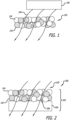
- FIG. 1 is a schematic representation of the structure of some embodiments of elements described herein.
- a transparent photocatalytic composition 100 is formed of a photocatalyst material 102 and a co-catalyst 104.
- Light waves 106 are emitted from a source 108 external to transparent photocatalytic composition 100 in a direction through it.
- a photocatalytic element is provided, the element comprising the aforementioned transparent photocatalytic composition 100.
- the element can be a layer.
- the element can be a coating disposed over a substrate,
- the source 108 may be transparent photocatalytic composition 100 including at least one of photoluminescent (phosphorescent or fluorescent), incandescent, electro- or chemo- or sono- or mechano- or thermo-luminescent materials.
- Phosphorescent materials may include ZnS and aluminum silicate whereas fluorescent materials may include phosphors like YAG-Ce, Y 2 O 3 -Eu, various organic dyes etc.
- Incandescent materials may include carbon, tungsten while electroluminescent materials may include ZnS, InP, GaN, etc. It will be evident to one of ordinary skill in the art that any other kind of light generation mechanism would suffice for providing the energy to initiate photocatalysis e.g. sunlight, fluorescent lamp, incandescent lamp, light-emitting diode (LED) based lighting, sodium vapor lamp, halogen lamp, mercury vapor lamp, noble gas discharges, and flames.
- LED light-emitting diode
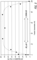
- Fig. 2 is a schematic representation of a system 200 of some embodiments of the elements described herein.
- a transparent photocatalytic element 202 is provided including a substrate 204 and transparent photocatalytic composition 100, the composition including at least one photocatalyst material 102 and a co-catalyst 104 contacting, at least in part, substrate 204.
- transparent photocatalytic composition 100 can be applied to or disposed upon substrate 204, at least a portion of transparent photocatalytic composition 100 contacting surface 206 of substrate 204 or a portion thereof.
- photocatalyst material 102 and a co-catalyst 104 can have refractive indices within about 0.75, about 0.50, about 0.20, or about 0.05 of each other.
- the at least one photocatalyst material 102 can be WO 3 and co-catalyst 104 can be CeO 2
- the respective refractive indices are 2.20 and 2.36.
- the photocatalytic composition is coated to a substrate in such a way that the photocatalyst composition can come into contact with light and material to be decomposed.
- the photocatalytic composition can be a separately formed layer, formed prior to disposition upon the substrate.
- the photocatalytic composition 100 can be formed upon the substrate surface, e.g., by vapor deposition like either chemical vapor deposition (CVD) or physical vapor deposition (PVD); laminating, pressing, rolling, soaking, melting, gluing, sol-gel deposition, spin coating; dip coating; bar coating; slot coating; brush coating; sputtering; thermal spraying including flame spray, plasma spray (DC or RF); high velocity oxy-fuel spray (HVOF) atomic layer deposition (ALD); cold spraying or aerosol deposition.
- the photocatalytic composition can be incorporated into the surface of the substrate, e.g., at least partially embedded within the surface.
- the photocatalyst composition substantially covers the substrate 204. In some embodiment, the photocatalyst composition contacts or covers at least about 75%, at least about 85%, or at least about 95% of the substrate surface 206.
- the Brunner Emmett Teller BET specific surface area of the photocatalyst is between 0.1-500 m 2 /g. In another embodiment, the BET specific surface area of the photocatalyst is between 10-50 m 2 /g.
- a photocatalytic layer including the aforementioned compositions of tungsten oxide to rare earth oxide.
- Also disclosed herein is a method for making a photocatalytic composition
- creating a dispersion comprising a photocatalyst, CeO 2 , and a dispersing media, wherein the respective photocatalyst and CeO 2 refractive indices are within at least 0.75 of each other, the molar ratio of the photocatalyst to CeO 2 being between 1-99 molar % photocatalyst and 99-1 molar % CeO 2 ; wherein the dispersion has about 2-50 wt% solid materials; applying the dispersion to a substrate; and heating the dispersion and the substrate at a sufficient temperature and length of time to evaporate substantially all the dispersing media from the dispersion.
- the dispersion is applied to cover the substrate, either in whole or in part, or to a surface of the substrate to create a coating or surface layer.
- a method for making a photocatalytic composition including mixing an aqueous dispersion of a visible light photocatalyst and CeO 2 , the ratio of the photocatalyst to CeO 2 being between 40-60 molar % photocatalyst and 60-40 molar % CeO 2 ; adding sufficient dispersing media, e.g. water, to attain a dispersion of about 10-30 wt% solid materials; applying the dispersion to a substrate; and heating the substrate at a sufficient temperature and length of time to evaporate substantially all the water from the dispersion and the substrate.
- the CeO 2 can be a sol.
- the photocatalyst material is added to the CeO 2 sol.
- the CeO 2 is added to a photocatalyst dispersion.
- both the photocatalyst dispersion and CeO 2 sol or dispersion are prepared separately and then mixed together to create the dispersion.
- the ratio of the photocatalyst to CeO 2 may be about 2:3 to about 3:2, such as between 40-60 molar % photocatalyst and 60-40 molar % CeO 2 . In another embodiment, the ratio of photocatalyst to CeO 2 is about 1:1 [50 molar % to 50 molar %]. In some embodiments, the CeO 2 is a sol.
- the amount of dispersing media, e.g. water, added is sufficient to attain a dispersion of about 2-50 wt%, about 10-30 wt%, about 15-25 wt% solid materials. In another embodiment, the amount of dispersing media, e.g., water, added is sufficient to attain a dispersion of about 20 wt% solid materials
- the mixture covered substrate is heated at a sufficient temperature and/or sufficient length of time to substantially remove the dispersing media. In some embodiments at least 90%, at least 95%, at least 99% of the dispersing media is removed. In another embodiment, the dispersion covered substrate is heated at a temperature between about room temperature and 500°C. In another embodiment, the dispersion covered substrate is heated to a temperature between about 90°C and about 150°C. In another embodiment, the dispersion covered substrate is heated to a temperature of about 120°C.
- the temperature below 500°C may reduce the possibility of thermal deactivation of the photocatalytic material, for example due to photocatalytic material phase change to a less active phase (highly-active anatase TiO 2 to less active rutile), dopant diffusion, dopant inactivation, loaded material decomposition or coagulation (reduction in total active surface area).
- the dispersion covered substrate is heated for a time between about 10 seconds and about 2 hours. In another embodiment, the mixture covered substrate is heated for a time of about 1 hour.
- the dispersions described herein can be applied to virtually any substrate.
- Other methods of applying the dispersion to a substrate can include slot/dip/spin coating, brushing, rolling, soaking, melting, gluing, or spraying the dispersion on a substrate.
- a proper propellant can be used to spray a dispersion onto a substrate.
- the substrate need not be capable of transmitting light.
- the substrate may be a common industrial or household surface on which a dispersion can be directly applied.
- Substrates can include, glass (e.g., windows), walls (e.g., drywall), stone (e.g., granite counter tops), masonry (e.g., brick walls), metals (e.g. stainless steel), woods, plastics, other polymeric surfaces, ceramics, and the like.
- Dispersions in such embodiments can be formulated as paints, liquid adhesives, on tape, on wallpapers, on drapes, on lamp shades, on light covers, on table or counter surface coverings, and the like.
- a photocatalyst composition may be capable of photocatalytically decomposing an organic compound, such as an aldehyde, including acetaldehyde formaldehyde, propionaldehyde, etc.; a hydrocarbon, such as an alkane, including methane, ethane, propane, butane, etc.; an aromatic hydrocarbon, such as benzene, naphthalene, anthracene, etc.; crude oil, or fraction thereof; dyes such as anthocyanins, methylene blue, basic blue 41; volatile organic compounds, such as methane, ethane, propane, butane, benzene, toluene, acetone, diethyl ether, methanol, ethanol, isopropyl alcohol, formaldehyde, ethyl acetate, xylene, etc.; NOx, such as NO, NO 2 , N 2 O, HONO,; SO x , such as SO 2 , SO
- a photocatalyst sample is dispersed in water or other solvent including methanol or ethanol.
- a binder may be added to this dispersion in such a way as to produce a final dispersion with 10-50% solid content.
- the dispersed sample can be homogenized using an ultrasonic probe.
- the dispersion can then be applied on a substrate.
- the substrate-applied dispersion combination can then be heated to about 120°C, thereby evaporating substantially all of the dispersant. Thereafter it can be subjected to high intensity UV illumination for about one hour for producing a pristine photocatalyst surface.
- This photocatalyst composition/substrate can be placed in a Tedlar Bag (5L) which can then be filled with about 3L air from a compressed air source. Thereafter, acetaldehyde from a calibration-grade source can be added to achieve a final acetaldehyde concentration of about 80 ppm as measured using a calibrated gas chromatograph equipped with a high sensitivity flame ionization detector (GC-FID).
- GC-FID high sensitivity flame ionization detector
- This gas bag sample can be equilibrated in the dark for about an hour and gas chromatography and flame ionization detection (GC-FID) can be used to confirm a stable concentration of acetaldehyde.
- GC-FID gas chromatography and flame ionization detection
- a monochromatic blue light-emitting diode array (455 nm) with 200 mW/cm 2 intensity of illumination at the exposure plane can be then used to irradiate the bag.
- Gas samples can be collected from the bag using an automated system and analyzed using the GC-FID. Temporal variation of the concentration of acetaldehyde can be determined from the area under the corresponding peak of the chromatogram.
- Other suitable gas detection scheme like Gastec gas detection tubes may also be used for determining the acetaldehyde concentration in the bag.
- the gas decomposition rate (%) can be set as a value calculated based on formula [(X-Y)/X ⁇ 100], where X represents a gas concentration before light irradiation and Y represents a gas concentration when the gas concentrations are measured.
- the acetaldehyde decomposition rate provided by the desired level of photocatalytic activity is at least about 10% in about 1 hour with above-mentioned illumination. In a preferred embodiment, the decomposition rate is at least about 30% in about 1 hour. In a more preferred embodiment, the rate is 50% in about 1 hour. In another embodiment, the decomposition rate is at least about 80% in about 1 hour.
- a photocatalyst material contains the photocatalyst powder according to the embodiment whose content falls within a range of not less than 0.1 molar % nor more than 99 molar %.
- a photocatalyst coating material contains the photocatalyst material according to the embodiment whose content falls within a range of not less than 1 molar % nor more than 90 molar %.
- the photocatalyst material, compositions, and dispersions described herein can be used as a disinfectant, an odor eliminator, a pollutant eliminator, a self-cleaner, an antimicrobial agent and the like.
- the materials, compositions, and dispersions can be used to interact with air, liquid, microbial and/or solid substances. In one embodiment, they can be used to clean air such as in confined environments such as in aircraft fuselages or in more contaminated environments such as auto garages. In other embodiments, they can be used for antimicrobial properties such as to coat surfaces in need of disinfection such as food service or production facilities or hospitals or clinics.
- methods are utilized wherein polluted air is exposed to light and a photocatalyst material, composition, or dispersion as described herein thereby removing pollutants from the air.
- light and a photocatalyst material, composition, or dispersion can remove about 50%, about 60%, about 70%, about 80%, about 90%, about 95% or more of the pollution in the air.
- methods are utilized wherein polluted water is exposed to light and a photocatalyst material, composition, or dispersion as described herein thereby reducing the amount of contaminant in the water.
- light and a photocatalyst material, composition, or dispersion can remove about 50%, about 60%, about 70%, about 80%, about 90%, about 95% or more of the pollution from the water.
- biological materials can include food products.
- light and a photocatalyst material, composition, or dispersion can remove about 50%, about 60%, about 70%, about 80%, about 90%, about 95% or more of the contamination from the biological material in the air.
- WO 3 photocatalyst 200 mg was added to water.
- the resulting dispersion was then added to 740 mg of CeO 2 sol (Nissan Chemical NanoUse CE-20B).
- the mole ratio of CeO 2 and WO 3 was chosen to be 1:1 (50 molar % to 50 molar %).
- a sufficient amount of RO (reverse osmosis treated) water 800mg was added to the resulting dispersion in order to make a coating solution which is about 20 wt% solid materials in water.
- the resulting dispersion was homogenized using an ultrasonic homogenizer.
- a glass substrate (50 mm x 75 mm) was coated with the prepared resultant by using a spin coater (1200 rpm/ 40 sec). The coated substrate was heated for about 2 minutes at about 120°C. The resulting coated substrate was transparent (about 86% at about 555 nm). Photocatalytic activity was determined by monitoring the acetaldehyde degradation ratio to about 81% after 1 hour of blue light-emitting diode (LED) (455 nm, 200 mW/cm 2 ) irradiation.
- LED blue light-emitting diode
- Coated substrate 2 was made in a similar manner to Example 1, except that SiO 2 sol (Nissan Chemical SNOWTEX O, 258 mg) was added instead of CeO 2 sol.
- the resulting coated substrate was transparent (90% at about 555 nm). Photocatalytic activity as determined by the acetaldehyde degradation ratio was about 50% after irradiation under conditions similar to Example 1.
- Coated substrate 3 was made in a similar manner to Example 1, except that SiO 2 sol (Nissan-Chemical SNOWTEX 20L, 258 mg) was added instead of CeO 2 sol.
- the resulting obtained substrate was transparent (91% at 555 nm). Photocatalytic activity as determined by the acetaldehyde degradation ratio was about 67% after irradiation under conditions similar to Example 1.
- Comparative Example 1 was prepared in a manner similar to Example 1, except that silicone resin (Shin-Etsu Chemical, SCR-1012) was used instead of CeO 2 sol. The ratio of WO 3 was about 20 wt% in silicone resin. Glass substrate (50 mm x 75 mm) was coated with the prepared solution by doctor blade. After 120°C heating for curing, the obtained substrate was translucent. The resulting obtained substrate exhibited a transparency of about 75% at 555 nm. Photocatalytic activity as determined by the acetaldehyde degradation ratio was about 1% after irradiation under conditions similar to Example 1.
- Comparative Example 2 was prepared in a manner similar to Example 1, except that poly (methyl methacrylate) (PMMA) was dispersed in acetone. The ratio of WO 3 was about 20 wt% in PMMA and no water was added. Glass substrate (50 mm x 75 mm) was coated with the prepared solution by doctor blade. After 120°C heating for curing, the obtained substrate was translucent. The resulting obtained substrate exhibited a transparency of about 78% at 555 nm. The acetaldehyde degradation ratio was 0.5% after irradiation under conditions similar to Example 1.
- PMMA poly (methyl methacrylate)
- WO 3 (0.8g) was added to Al 2 O 3 sol (Nissan Chemical Alumina-sol200, 5g). The mole ratio of Al 2 O 3 and WO 3 was chosen to be 1:1 by weight. Then RO water (5.8g) was added in order to make a coating solution which is 14 wt% solid materials in water. A glass substrate (50 mm x 75 mm) was coated with the prepared solution by using a spin coater (1200 rpm/40 sec). After heating at about 120°C for evaporation of the liquid, the obtained substrate was translucent. The resulting obtained substrate was transparent (91% at 555nm). The acetaldehyde degradation ratio was about 0% after irradiation under conditions similar to Example 1.
- Example 4 A coating solution was prepared with sufficient CeO 2 sol (Nissan Chemical NanoUse CE-20B) to attain a mole ratio of CeO 2 and WO 3 of about 1:1 (50 molar % to 50 molar %).
- Example 4a was then made by spin coating the substrate of Example 4, as discussed above, with the CeO 2 coating solution in a manner similar to that described in Example 1.
- GC-FID Gas Chromotagraphy-Flame Ionization Detector
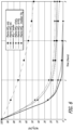
- FIG. 3 is a graph illustrating T-binder performance data. The graph shows that generally when a T-binder is combined with WO 3 , performance is improved when compared to bare WO 3 .
- WO 3 Global Tungsten & Powder, Towanda, PA, USA [GTP]
- WO 3 Global Tungsten & Powder, Towanda, PA, USA [GTP]
- high purity alumina ball mill jars containing about 50 g of ZrO 2 balls of about 3 mm in diameter and was ground by ball mill (SFM-1 model Desktop Planetary Ball Miller (MTI Corp. location) in 25 mL methanol for about 4 hours to obtain ground WO 3 (GTP) with a smaller particle size.
- Plasma-WO 3 was made in a manner similar to that described in U.S. Patent 8,003,563 , which is hereby incorporated by reference in its entirety.
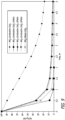
- Example 8 additional slides were made in a manner similar to that of Example 1, except that the amount of CeO 2 sol added was varied to attain different molar ratios of WO 3 :CeO 2 (e.g., 0%, 0.1%, 5%, 10%, 30%, 50%, 75%, 90%, 95%, 100%) ((100-x) WO 3 + (x) T-binder).
- Fig. 5 shows the acetaldehyde degradation estimated after 1 hour of exposure to 270 mW/cm 2 blue LED array light.
- Example 9 an additional slide was made in the following manner: plasma WO 3 powder (130 mg) and CeO 2 powder (96.5 mg) (about a 1:1 mole ratio) were dispersed first in RO water (20 wt% of solid) and bath sonicated (VWR B3500A-MT) for about 10 minutes and then probe sonicated (Sonic dismembrator Model 100, continuous mode) for about 5 minutes. Then, the mixture/composite/blend was spin coated on a 75 mm X 50 mm glass slide and annealed as described in Example 4.
- plasma WO 3 powder (130 mg) and CeO 2 powder (96.5 mg) (about a 1:1 mole ratio) were dispersed first in RO water (20 wt% of solid) and bath sonicated (VWR B3500A-MT) for about 10 minutes and then probe sonicated (Sonic dismembrator Model 100, continuous mode) for about 5 minutes. Then, the mixture/composite/blend was spin coated on a 75 mm X 50 mm
- each glass slide made above was tested in a manner similar to that described immediately above, except that each slide was exposed to varied light intensity (from about 50mW/cm 2 to about 350 mW/cm 2 ). The results are shown in Fig. 7 .
- a clean petri dish was wiped with ethanol and the inside surface of the dish was ionized with a corona device for about 1 to 2 minutes.
- the homogeneous sample of each compound was poured into the treated petri dish and then heated at about 120°C while swirling to achieve uniform distribution of the sample as it dried. After the sample had dried, the petri dish was placed under a UV lamp (300W) for about 1 hour. The petri dish was then inserted into a Tedlar bag and tested in a manner similar to that described for Example 4. The results are shown in Fig. 8 .
- Tin (II) 2-ethylhexanoate also known as tin (II) octoate and/or stannous octoate
- 5 g of Ce(NO 3 ) 3 ⁇ 6H20 (Sigma Aldrich, St. Louis, MO, USA)
- 3.0 g of ammonium nitrate (NH 4 NO 3 ) (Sigma Aldrich, St. Louis, MO, USA) were dissolved in about 25 mL of RO treated water. 1.129 g maleic hydrazide was then added just before the mixture was heated to about 150° C and stirred for about 20 minutes.
- the resultant precursor mixture was then heated at about 450°C for about 40 minutes in a preheated muffle furnace under ambient atmosphere and pressure conditions.
- the resultant powder was annealed at about 500°C for about 20 minutes.
- the resultant powder was mixed with WO 3 in a 1:1 molar ratio used in a manner similar to that described in Example 1 to make a coated glass slide and then was tested on its ability to degrade acetylaldehyde following the procedure described in Example 4.
- Example 36 Combination of combustion Ti(O,C,N) 2 :Sn and Plasma CeO 2 towards Acetaldehyde degradation (not in accordance with the claimed invention):
- Ti(O,C,N) 2 :Sn was combined with plasma CeO 2 powder (1:1 mole ratio) in a similar manner to that described in Example 1, except that Ti(O,C,N) 2 :Sn powder was used instead of WO 3 powder, and was spin coated on a glass micro slide as described in Example 1.
- the Ti(O,C,N) 2 :Sn was synthesized as described in co-pending U.S.
- Patent Provisional Application Serial Number 61/608,754, filed March 8, 2012 which is hereby incorporated by reference in its entirety, by an aqueous combustion method employing glycine (1.4 g) as a completely decomposable fuel in addition to titanium (IV) bis ammonium lactate dihydroxide (7mL of 50 wt% aqueous solution), tin octoate (0.883 g) and ammonium nitrate (3.5 g) at 300°C followed by annealing at 400°C for 30 min in the box furnace.
- a glass slide made in a manner similar to that of the previous examples was tested for acetaldehyde degradation as also earlier described in Example 4 (at 270 mW/cm 2 light intensity).
- a dispersion including a photocatalyst compostion as described herein is provided as a coating on a thin adhesive film.
- This adhesive film is used to coat the ceiling of a Boeing 737.
- the photocatalyst compostion can react with ambient light from light emitting diode light fixtures above the overhead bins to generate reactive airborne species that can reduce odor in the air.
- a photocatalyst resin capable of being applied as a spray is provided to a food preparation factory to coat its work surfaces.
- the resin can be applied in a heated or unheated state in order to properly bond with a work surface. All surfaces that are to come into contact with food in the factory are sprayed with the resin.
- the factory is equipped with organic light emitting diode light fixtures for general lighting.
- This ambient light can react with the resin surface thereby creating oxygen radicals on the surface.
- These radicals can react with food contaminants thereby rendering the food safe.
- instances of bacteria spreading into the food supply has reduced 50%.
Landscapes
- Chemical & Material Sciences (AREA)
- Engineering & Computer Science (AREA)
- Materials Engineering (AREA)
- Organic Chemistry (AREA)
- Chemical Kinetics & Catalysis (AREA)
- Catalysts (AREA)
- Disinfection, Sterilisation Or Deodorisation Of Air (AREA)
- Physical Water Treatments (AREA)
- Treatment Of Water By Oxidation Or Reduction (AREA)
- Apparatus For Disinfection Or Sterilisation (AREA)
- Paints Or Removers (AREA)
Applications Claiming Priority (3)
| Application Number | Priority Date | Filing Date | Title |
|---|---|---|---|
| US201261585732P | 2012-01-12 | 2012-01-12 | |
| US13/738,243 US9987621B2 (en) | 2012-01-12 | 2013-01-10 | Transparent photocatalyst coating |
| PCT/US2013/021318 WO2013106776A2 (en) | 2012-01-12 | 2013-01-11 | Transparent photocatalyst coating |
Publications (3)
| Publication Number | Publication Date |
|---|---|
| EP2802412A2 EP2802412A2 (en) | 2014-11-19 |
| EP2802412A4 EP2802412A4 (en) | 2016-01-20 |
| EP2802412B1 true EP2802412B1 (en) | 2023-05-24 |
Family
ID=48779260
Family Applications (1)
| Application Number | Title | Priority Date | Filing Date |
|---|---|---|---|
| EP13735689.5A Active EP2802412B1 (en) | 2012-01-12 | 2013-01-11 | Transparent photocatalyst coating |
Country Status (7)
| Country | Link |
|---|---|
| US (1) | US9987621B2 (cg-RX-API-DMAC7.html) |
| EP (1) | EP2802412B1 (cg-RX-API-DMAC7.html) |
| JP (2) | JP6093375B2 (cg-RX-API-DMAC7.html) |
| KR (1) | KR102058839B1 (cg-RX-API-DMAC7.html) |
| CN (1) | CN104487166B (cg-RX-API-DMAC7.html) |
| TW (1) | TWI592210B (cg-RX-API-DMAC7.html) |
| WO (1) | WO2013106776A2 (cg-RX-API-DMAC7.html) |
Families Citing this family (52)
| Publication number | Priority date | Publication date | Assignee | Title |
|---|---|---|---|---|
| KR101104262B1 (ko) * | 2008-12-31 | 2012-01-11 | 주식회사 노루홀딩스 | 자기세정성 부재 및 그 제조방법 |
| US9044746B2 (en) * | 2010-09-16 | 2015-06-02 | Northeastern University | Photocatalyst with enhanced stability for hydrogen production and oxidative reactions |
| US9987621B2 (en) | 2012-01-12 | 2018-06-05 | Nitto Denko Corporation | Transparent photocatalyst coating |
| JP2013245133A (ja) * | 2012-05-25 | 2013-12-09 | National Institute For Materials Science | チタン酸化物とそれを用いた黄色顔料及び光触媒 |
| US9376332B2 (en) | 2013-03-15 | 2016-06-28 | Nitto Denko Corporation | Multivalence photocatalytic semiconductor elements |
| US10702854B2 (en) | 2013-05-13 | 2020-07-07 | Dalian Institute Of Chemical Physics, Chinese Academy Of Sciences | Oxygen-free direct conversion of methane and catalysts therefor |
| CN104148101B (zh) * | 2013-05-13 | 2016-12-28 | 中国科学院大连化学物理研究所 | 一种甲烷无氧直接制烯烃的方法及其催化剂 |
| TWI627994B (zh) | 2013-07-05 | 2018-07-01 | 日東電工股份有限公司 | 用於分解污染物之過濾元件、用於分解污染物之系統及使用該系統之方法 |
| US10391482B2 (en) | 2013-07-05 | 2019-08-27 | Nitto Denko Corporation | Transparent photocatalyst coating and methods of manufacturing the same |
| US9587877B2 (en) * | 2013-07-09 | 2017-03-07 | Nitto Denko Corporation | Organic electroluminescent device having a photocatalyst layer |
| JP5630679B1 (ja) * | 2013-09-08 | 2014-11-26 | 株式会社E・テック | 揮発性消毒剤、揮発性消毒剤の製造方法 |
| WO2015064773A1 (en) * | 2013-11-04 | 2015-05-07 | Nitto Denko Corporation | Photocatalytic coating and method of making same |
| CN105744893A (zh) | 2013-11-12 | 2016-07-06 | 日东电工株式会社 | 透声性抗微生物表面 |
| WO2015137511A1 (en) * | 2014-03-11 | 2015-09-17 | Nitto Denko Corporation | Photocatalytic element |
| WO2015200161A1 (en) * | 2014-06-23 | 2015-12-30 | WELL Shield LLC | Reduction of infections in healthcare settings using photocatalytic compositions |
| JP6276123B2 (ja) * | 2014-07-04 | 2018-02-07 | シャープ株式会社 | 光触媒材料 |
| WO2016033554A1 (en) | 2014-08-29 | 2016-03-03 | Nitto Denko Corporation | Photocatalytic coating and method of making same |
| WO2016040667A1 (en) * | 2014-09-10 | 2016-03-17 | Nitto Denko Corporation | Improved air purification system and method for removing formaldehyde |
| US10213780B2 (en) | 2014-09-12 | 2019-02-26 | Nitto Denko Corporation | Multivalence semiconductor photocatalytic materials |
| FR3026966B1 (fr) * | 2014-10-14 | 2019-09-27 | IFP Energies Nouvelles | Composition photocatalytique comprenant des particules metalliques et deux semi-conducteurs dont un en oxyde d'indium |
| WO2016077376A1 (en) | 2014-11-10 | 2016-05-19 | Nitto Denko Corporation | Acoustically transparent antimicrobial surfaces |
| CN104944369B (zh) * | 2014-12-03 | 2018-04-17 | 江苏大学 | 一种银修饰钽酸钠等离子催化剂分解水制氢的方法 |
| US9409791B2 (en) * | 2014-12-29 | 2016-08-09 | Council Of Scientific & Industrial Research | Photocatalytic degradation of pharmaceutical drugs and dyes using visible active biox photocatalyst |
| US10583421B2 (en) | 2015-05-14 | 2020-03-10 | Nitto Denko Corporation | Photocatalytic coated granules and method of making same |
| WO2016194354A1 (en) | 2015-05-29 | 2016-12-08 | Nitto Denko Corporation | Photocatalyst coating |
| US10125031B2 (en) | 2015-06-08 | 2018-11-13 | King Fahd University Of Petroleum And Minerals | Method for disinfecting a fluid with a palladium-doped tungsten trioxide photo-catalyst |
| WO2017061124A1 (en) * | 2015-10-06 | 2017-04-13 | Nitto Denko Corporation | Photocatalytic element |
| CN106995919A (zh) * | 2016-01-22 | 2017-08-01 | 中国科学院金属研究所 | 一种冷喷涂制备光催化二氧化钛陶瓷涂层的方法 |
| CN107441906B (zh) * | 2016-07-15 | 2020-06-12 | 杭州富阳何氏化纤助剂有限公司 | 一种去除石化工业废气中苯系物的处理方法 |
| KR102056630B1 (ko) * | 2016-08-31 | 2020-01-22 | (주)엘지하우시스 | 가시광 활성 복합 광촉매 및 이를 포함하는 복합재 |
| JP7218841B2 (ja) * | 2016-12-27 | 2023-02-07 | オーニット株式会社 | 脱臭方法及び脱臭装置 |
| CN107238674A (zh) * | 2017-06-12 | 2017-10-10 | 富思特新材料科技发展股份有限公司 | 一种光催化涂料净化二氧化硫的检测方法 |
| WO2019039021A1 (ja) * | 2017-08-22 | 2019-02-28 | 三菱電機株式会社 | 光触媒、光触媒担持体、光触媒の製造方法及び光触媒担持体の製造方法 |
| JP6989762B2 (ja) * | 2017-08-25 | 2022-02-03 | 富士通株式会社 | 光化学電極、及びその製造方法、並びに光電気化学反応装置 |
| JP6868251B2 (ja) * | 2018-03-30 | 2021-05-12 | 地方独立行政法人神奈川県立産業技術総合研究所 | 抗ウイルス剤 |
| JP7084509B2 (ja) | 2018-06-27 | 2022-06-14 | 日東電工株式会社 | 紫外活性化光触媒材料及び揮発性化合物分解におけるその使用 |
| JP7234530B2 (ja) * | 2018-08-06 | 2023-03-08 | 栗田工業株式会社 | 燃料ガス吸着カラムの再生方法 |
| CN108940317A (zh) * | 2018-08-21 | 2018-12-07 | 三明学院 | 一种Fe3O4@C-CoS-TiO2复合光催化剂及其制备方法 |
| CN109225214A (zh) * | 2018-09-13 | 2019-01-18 | 长安大学 | Pt-WO3-TiO2复合光催化剂、其制备方法、路用多功能涂层材料及其制备方法 |
| KR102223134B1 (ko) * | 2019-03-21 | 2021-03-05 | 한국과학기술연구원 | 수처리 장치 |
| CN110302668B (zh) * | 2019-07-26 | 2022-02-15 | 中科新天地(合肥)环保科技有限公司 | 一种有机废气反应装置用的等离子体协同光催化装卸机构 |
| GR1010949B (el) | 2020-04-03 | 2025-05-26 | Pcn Materials Ike, | Φωτοκαταλυτης διοξειδιου του τιτανιου με πολυ-στοιχειακες προσμιξεις και μεθοδος παρασκευης αυτου |
| US10888845B1 (en) * | 2020-07-17 | 2021-01-12 | King Abdulaziz University | Graphene-tungsten oxide-metal boride/hydroxide photocatalysts, and methods for organic pollutant degradation and hydrogen production |
| KR102379851B1 (ko) * | 2020-10-12 | 2022-03-28 | 한림대학교 산학협력단 | 철 3가 이온을 포함하는 광촉매 기반 수처리 시스템 및 이를 이용한 수처리 방법 |
| TW202241586A (zh) * | 2021-02-03 | 2022-11-01 | 安永成生技股份有限公司 | 抗菌及抗病毒的光催化組成物及製造包含該光催化組成物的基材的方法 |
| CN113070056B (zh) * | 2021-03-22 | 2022-11-08 | 南昌大学 | 一种三维有序网状结构五氧二钽光催化材料的通用合成方法 |
| CN113893846B (zh) * | 2021-11-18 | 2022-06-28 | 广东粤绿环境工程有限公司 | 一种锡、铈-钛酸锶固溶体压电制氢催化剂及其制备方法与应用 |
| CN114433449B (zh) * | 2022-03-04 | 2023-04-28 | 浙江中科森态富氧科技有限公司 | 一种绿色长效光催化负氧离子释放涂层的制备方法及其产品 |
| CN115106078A (zh) * | 2022-06-24 | 2022-09-27 | 北京化工大学常州先进材料研究院 | 一种改性TiO2光催化剂的制备方法 |
| CN115010132B (zh) * | 2022-07-11 | 2023-11-03 | 中船(邯郸)派瑞特种气体股份有限公司 | 一种高纯一氧化碳电子气体的制备纯化方法 |
| US20240198322A1 (en) * | 2022-12-14 | 2024-06-20 | Uniplatek Co., Ltd | Visible light-sensitive photocatalyst composition and a visible light-sensitive photocatalyst film comprising the same |
| CN118022838B (zh) * | 2024-02-01 | 2024-08-16 | 广州然益生物环保科技有限公司 | 一种可降解挥发性有机化合物气体的制剂及其制备方法 |
Citations (1)
| Publication number | Priority date | Publication date | Assignee | Title |
|---|---|---|---|---|
| EP2248586A1 (en) * | 2008-01-28 | 2010-11-10 | Kabushiki Kaisha Toshiba | Visible light response-type photocatalyst powder, visible light response-type photocatalyst material using the visible light response-type photocatalyst powder, photocatalyst coating material, and photocatalyst product |
Family Cites Families (36)
| Publication number | Priority date | Publication date | Assignee | Title |
|---|---|---|---|---|
| US6193856B1 (en) | 1995-08-23 | 2001-02-27 | Asahi Glass Company Ltd. | Target and process for its production, and method for forming a film having a highly refractive index |
| KR100377606B1 (ko) | 1995-09-15 | 2003-08-25 | 로디아 쉬미 | 이산화티타늄-기재광촉매코팅기판,및이산화티타늄-기재유기분산액 |
| JPH11226421A (ja) | 1998-02-13 | 1999-08-24 | Toshiba Lighting & Technology Corp | 光触媒体および機能体 |
| JP2000218161A (ja) * | 1999-01-29 | 2000-08-08 | Sharp Corp | 光触媒体 |
| JP4300280B2 (ja) | 1999-12-06 | 2009-07-22 | 日東電工株式会社 | 光触媒体 |
| AU783565B2 (en) | 2000-10-20 | 2005-11-10 | Sumitomo Chemical Company, Limited | Photocatalyst, process for producing the same and photocatalyst coating composition comprising the same |
| JP2002126517A (ja) * | 2000-10-20 | 2002-05-08 | Sumitomo Chem Co Ltd | 光触媒体、その製造方法およびそれを用いてなる光触媒体コーティング剤 |
| JP4075482B2 (ja) * | 2001-08-08 | 2008-04-16 | 住友金属鉱山株式会社 | 可視光域でも触媒活性を有する光触媒 |
| JP3849008B2 (ja) * | 2001-09-20 | 2006-11-22 | 独立行政法人産業技術総合研究所 | 高性能自動調光窓コーティング材料 |
| WO2003070810A2 (en) | 2002-02-15 | 2003-08-28 | Nanophase Technologies Corporation | Composite nanoparticle materials and method of making the same |
| JP2004066218A (ja) | 2002-06-12 | 2004-03-04 | Toshiba Lighting & Technology Corp | 光触媒体 |
| JP5031168B2 (ja) | 2002-08-22 | 2012-09-19 | 株式会社デンソー | 触媒体 |
| EP1689525B1 (en) | 2003-10-30 | 2009-03-18 | Showa Denko K.K. | Transparent film-forming composition |
| US20050129591A1 (en) | 2003-12-16 | 2005-06-16 | Di Wei | Bifunctional layered photocatalyst/thermocatalyst for improving indoor air quality |
| JP4803414B2 (ja) | 2004-01-16 | 2011-10-26 | 学校法人東京理科大学 | 新規z−スキーム型可視光活性な水の完全分解用光触媒系及び前記触媒を用いた水の完全分解方法 |
| JP4393963B2 (ja) | 2004-03-17 | 2010-01-06 | 住友化学株式会社 | 光触媒体コーティング液 |
| CN1597090A (zh) | 2004-04-01 | 2005-03-23 | 福州大学 | 无需高温烧结处理的光催化剂的制备及其应用 |
| JPWO2006025535A1 (ja) | 2004-09-03 | 2008-05-08 | Jsr株式会社 | コーティング用組成物および下塗り剤、ならびに該組成物からなる塗膜を有する積層体、光触媒コーティングフィルムおよび成形体 |
| WO2007022462A2 (en) * | 2005-08-19 | 2007-02-22 | North Carolina State University | Solar photocatalysis using transition-metal oxides combining d0 and d6 electron configurations |
| US7892662B2 (en) | 2006-04-27 | 2011-02-22 | Guardian Industries Corp. | Window with anti-bacterial and/or anti-fungal feature and method of making same |
| WO2007143042A2 (en) * | 2006-06-01 | 2007-12-13 | Carrier Corporation | Deactivation resistant photocatalysts |
| EP2035493A4 (en) * | 2006-06-01 | 2012-05-30 | Carrier Corp | PHOTO CATALYSTS WITH VOLUMETRIC ACTIVITY AND LONG SERVICE LIFE |
| GB0614164D0 (en) | 2006-07-17 | 2006-08-23 | Isis Innovation | Metal oxynitride |
| CN101641292B (zh) | 2007-03-23 | 2012-10-17 | 株式会社东芝 | 生产用于光催化剂的三氧化钨粉末的方法,用于光催化剂的三氧化钨粉末,及光催化剂产品 |
| JP2009106897A (ja) | 2007-10-31 | 2009-05-21 | Toshiba Lighting & Technology Corp | 光触媒粒子及び光触媒塗料 |
| CN101259422A (zh) | 2008-04-24 | 2008-09-10 | 南开大学 | 高效率纳米Ti1-xO2-Snx/TiO2-x-Nx复合薄膜可见光催化剂的制备方法 |
| KR20090127820A (ko) | 2008-06-09 | 2009-12-14 | 스미또모 가가꾸 가부시끼가이샤 | 옥살산지르코늄 졸 |
| EP2383319B1 (en) | 2008-12-27 | 2018-03-21 | JGC Catalysts and Chemicals Ltd. | Coating composition containing high-refractive-index metal oxide fine particles, and curable coating film obtained by applying the coating composition onto base |
| CN102470358A (zh) | 2009-06-26 | 2012-05-23 | Toto株式会社 | 光催化剂涂装体及光催化剂涂布液 |
| JP2011020009A (ja) | 2009-07-13 | 2011-02-03 | Hokkaido Univ | 揮発性芳香族化合物分解用光触媒体および光触媒機能製品 |
| JP2011046602A (ja) * | 2009-07-31 | 2011-03-10 | Ohara Inc | ガラス粉粒体及びこれを含有するスラリー状混合物 |
| JP2011224534A (ja) | 2009-09-16 | 2011-11-10 | Sumitomo Chemical Co Ltd | 光触媒複合体、およびこれを用いた光触媒機能製品 |
| JP2011212613A (ja) * | 2010-03-31 | 2011-10-27 | Toshiba Corp | エアコン用抗ウイルス性フィルタ |
| CN101898139A (zh) | 2010-06-25 | 2010-12-01 | 张麒 | 氧化钨掺杂二氧化钛光催化剂的配方及制备方法 |
| CN102091589B (zh) | 2010-12-20 | 2012-10-31 | 大连工业大学 | SiO2-WO3复合气凝胶及其制备方法 |
| US9987621B2 (en) | 2012-01-12 | 2018-06-05 | Nitto Denko Corporation | Transparent photocatalyst coating |
-
2013
- 2013-01-10 US US13/738,243 patent/US9987621B2/en not_active Expired - Fee Related
- 2013-01-11 JP JP2014552352A patent/JP6093375B2/ja not_active Expired - Fee Related
- 2013-01-11 CN CN201380005340.7A patent/CN104487166B/zh not_active Expired - Fee Related
- 2013-01-11 KR KR1020147022357A patent/KR102058839B1/ko not_active Expired - Fee Related
- 2013-01-11 WO PCT/US2013/021318 patent/WO2013106776A2/en not_active Ceased
- 2013-01-11 EP EP13735689.5A patent/EP2802412B1/en active Active
- 2013-01-14 TW TW102101381A patent/TWI592210B/zh not_active IP Right Cessation
-
2016
- 2016-08-24 JP JP2016163471A patent/JP6170601B2/ja not_active Expired - Fee Related
Patent Citations (1)
| Publication number | Priority date | Publication date | Assignee | Title |
|---|---|---|---|---|
| EP2248586A1 (en) * | 2008-01-28 | 2010-11-10 | Kabushiki Kaisha Toshiba | Visible light response-type photocatalyst powder, visible light response-type photocatalyst material using the visible light response-type photocatalyst powder, photocatalyst coating material, and photocatalyst product |
Also Published As
| Publication number | Publication date |
|---|---|
| US9987621B2 (en) | 2018-06-05 |
| TW201332649A (zh) | 2013-08-16 |
| JP2015513306A (ja) | 2015-05-07 |
| JP6170601B2 (ja) | 2017-07-26 |
| EP2802412A2 (en) | 2014-11-19 |
| KR20140122720A (ko) | 2014-10-20 |
| WO2013106776A3 (en) | 2015-01-29 |
| TWI592210B (zh) | 2017-07-21 |
| CN104487166A (zh) | 2015-04-01 |
| WO2013106776A2 (en) | 2013-07-18 |
| KR102058839B1 (ko) | 2019-12-24 |
| US20130180932A1 (en) | 2013-07-18 |
| JP6093375B2 (ja) | 2017-03-08 |
| EP2802412A4 (en) | 2016-01-20 |
| CN104487166B (zh) | 2018-07-13 |
| JP2017018954A (ja) | 2017-01-26 |
Similar Documents
| Publication | Publication Date | Title |
|---|---|---|
| US9987621B2 (en) | Transparent photocatalyst coating | |
| US10710063B2 (en) | Transparent photocatalyst coating and methods of manufacturing the same | |
| US10556230B2 (en) | Photocatalyst coating | |
| EP2255878B1 (en) | Antibacterial material and antibacterial film and antibacterial member using the same | |
| US20170291164A1 (en) | Improved air purification system and method for removing formaldehyde | |
| US10835631B2 (en) | Photocatalytic element | |
| TW200940168A (en) | Visible light response-type photocatalyst powder, visible light response-type photocatalyst material using the visible light response-type photocatalyst powder, photocatalyst coating material, and photocatalyst product | |
| JP2009202152A (ja) | 可視光応答型光触媒粉末とそれを用いた可視光応答型の光触媒材料、光触媒塗料、光触媒製品 | |
| US10898890B2 (en) | Photocatalytic coating and method of making same | |
| KR102060521B1 (ko) | 가시광 활성 광촉매를 포함하는 방수제 |
Legal Events
| Date | Code | Title | Description |
|---|---|---|---|
| PUAI | Public reference made under article 153(3) epc to a published international application that has entered the european phase |
Free format text: ORIGINAL CODE: 0009012 |
|
| 17P | Request for examination filed |
Effective date: 20140812 |
|
| AK | Designated contracting states |
Kind code of ref document: A2 Designated state(s): AL AT BE BG CH CY CZ DE DK EE ES FI FR GB GR HR HU IE IS IT LI LT LU LV MC MK MT NL NO PL PT RO RS SE SI SK SM TR |
|
| RAP1 | Party data changed (applicant data changed or rights of an application transferred) |
Owner name: NITTO DENKO CORPORATION |
|
| R17D | Deferred search report published (corrected) |
Effective date: 20150129 |
|
| DAX | Request for extension of the european patent (deleted) | ||
| A4 | Supplementary search report drawn up and despatched |
Effective date: 20151217 |
|
| RIC1 | Information provided on ipc code assigned before grant |
Ipc: B01J 27/22 20060101ALI20151211BHEP Ipc: B01J 27/24 20060101AFI20151211BHEP Ipc: B01J 23/14 20060101ALI20151211BHEP Ipc: B01J 23/30 20060101ALI20151211BHEP |
|
| STAA | Information on the status of an ep patent application or granted ep patent |
Free format text: STATUS: EXAMINATION IS IN PROGRESS |
|
| 17Q | First examination report despatched |
Effective date: 20210520 |
|
| REG | Reference to a national code |
Ref country code: DE Ref legal event code: R079 Ref document number: 602013083838 Country of ref document: DE Free format text: PREVIOUS MAIN CLASS: B01J0027240000 Ipc: B01J0035000000 |
|
| GRAP | Despatch of communication of intention to grant a patent |
Free format text: ORIGINAL CODE: EPIDOSNIGR1 |
|
| STAA | Information on the status of an ep patent application or granted ep patent |
Free format text: STATUS: GRANT OF PATENT IS INTENDED |
|
| RIC1 | Information provided on ipc code assigned before grant |
Ipc: B01J 37/04 20060101ALI20221118BHEP Ipc: B01J 37/02 20060101ALI20221118BHEP Ipc: B01J 37/00 20060101ALI20221118BHEP Ipc: B01J 27/24 20060101ALI20221118BHEP Ipc: B01J 27/22 20060101ALI20221118BHEP Ipc: B01J 23/30 20060101ALI20221118BHEP Ipc: B01J 23/20 20060101ALI20221118BHEP Ipc: B01J 23/16 20060101ALI20221118BHEP Ipc: B01J 23/14 20060101ALI20221118BHEP Ipc: B01J 23/10 20060101ALI20221118BHEP Ipc: B01J 23/08 20060101ALI20221118BHEP Ipc: B01J 23/02 20060101ALI20221118BHEP Ipc: B01J 21/06 20060101ALI20221118BHEP Ipc: B01J 35/02 20060101ALI20221118BHEP Ipc: B01J 35/00 20060101AFI20221118BHEP |
|
| INTG | Intention to grant announced |
Effective date: 20221220 |
|
| RIN1 | Information on inventor provided before grant (corrected) |
Inventor name: MUKHERJEE, RAJESH Inventor name: SAMBANDAN, EKAMBARAM Inventor name: FUKUMURA, TAKUYA |
|
| GRAS | Grant fee paid |
Free format text: ORIGINAL CODE: EPIDOSNIGR3 |
|
| GRAA | (expected) grant |
Free format text: ORIGINAL CODE: 0009210 |
|
| STAA | Information on the status of an ep patent application or granted ep patent |
Free format text: STATUS: THE PATENT HAS BEEN GRANTED |
|
| AK | Designated contracting states |
Kind code of ref document: B1 Designated state(s): AL AT BE BG CH CY CZ DE DK EE ES FI FR GB GR HR HU IE IS IT LI LT LU LV MC MK MT NL NO PL PT RO RS SE SI SK SM TR |
|
| REG | Reference to a national code |
Ref country code: GB Ref legal event code: FG4D |
|
| REG | Reference to a national code |
Ref country code: CH Ref legal event code: EP |
|
| REG | Reference to a national code |
Ref country code: DE Ref legal event code: R096 Ref document number: 602013083838 Country of ref document: DE |
|
| REG | Reference to a national code |
Ref country code: AT Ref legal event code: REF Ref document number: 1569189 Country of ref document: AT Kind code of ref document: T Effective date: 20230615 |
|
| P01 | Opt-out of the competence of the unified patent court (upc) registered |
Effective date: 20230515 |
|
| REG | Reference to a national code |
Ref country code: IE Ref legal event code: FG4D |
|
| REG | Reference to a national code |
Ref country code: LT Ref legal event code: MG9D |
|
| REG | Reference to a national code |
Ref country code: NL Ref legal event code: MP Effective date: 20230524 |
|
| REG | Reference to a national code |
Ref country code: AT Ref legal event code: MK05 Ref document number: 1569189 Country of ref document: AT Kind code of ref document: T Effective date: 20230524 |
|
| PG25 | Lapsed in a contracting state [announced via postgrant information from national office to epo] |
Ref country code: SE Free format text: LAPSE BECAUSE OF FAILURE TO SUBMIT A TRANSLATION OF THE DESCRIPTION OR TO PAY THE FEE WITHIN THE PRESCRIBED TIME-LIMIT Effective date: 20230524 Ref country code: PT Free format text: LAPSE BECAUSE OF FAILURE TO SUBMIT A TRANSLATION OF THE DESCRIPTION OR TO PAY THE FEE WITHIN THE PRESCRIBED TIME-LIMIT Effective date: 20230925 Ref country code: NO Free format text: LAPSE BECAUSE OF FAILURE TO SUBMIT A TRANSLATION OF THE DESCRIPTION OR TO PAY THE FEE WITHIN THE PRESCRIBED TIME-LIMIT Effective date: 20230824 Ref country code: NL Free format text: LAPSE BECAUSE OF FAILURE TO SUBMIT A TRANSLATION OF THE DESCRIPTION OR TO PAY THE FEE WITHIN THE PRESCRIBED TIME-LIMIT Effective date: 20230524 Ref country code: ES Free format text: LAPSE BECAUSE OF FAILURE TO SUBMIT A TRANSLATION OF THE DESCRIPTION OR TO PAY THE FEE WITHIN THE PRESCRIBED TIME-LIMIT Effective date: 20230524 Ref country code: AT Free format text: LAPSE BECAUSE OF FAILURE TO SUBMIT A TRANSLATION OF THE DESCRIPTION OR TO PAY THE FEE WITHIN THE PRESCRIBED TIME-LIMIT Effective date: 20230524 |
|
| PG25 | Lapsed in a contracting state [announced via postgrant information from national office to epo] |
Ref country code: RS Free format text: LAPSE BECAUSE OF FAILURE TO SUBMIT A TRANSLATION OF THE DESCRIPTION OR TO PAY THE FEE WITHIN THE PRESCRIBED TIME-LIMIT Effective date: 20230524 Ref country code: PL Free format text: LAPSE BECAUSE OF FAILURE TO SUBMIT A TRANSLATION OF THE DESCRIPTION OR TO PAY THE FEE WITHIN THE PRESCRIBED TIME-LIMIT Effective date: 20230524 Ref country code: LV Free format text: LAPSE BECAUSE OF FAILURE TO SUBMIT A TRANSLATION OF THE DESCRIPTION OR TO PAY THE FEE WITHIN THE PRESCRIBED TIME-LIMIT Effective date: 20230524 Ref country code: LT Free format text: LAPSE BECAUSE OF FAILURE TO SUBMIT A TRANSLATION OF THE DESCRIPTION OR TO PAY THE FEE WITHIN THE PRESCRIBED TIME-LIMIT Effective date: 20230524 Ref country code: IS Free format text: LAPSE BECAUSE OF FAILURE TO SUBMIT A TRANSLATION OF THE DESCRIPTION OR TO PAY THE FEE WITHIN THE PRESCRIBED TIME-LIMIT Effective date: 20230924 Ref country code: HR Free format text: LAPSE BECAUSE OF FAILURE TO SUBMIT A TRANSLATION OF THE DESCRIPTION OR TO PAY THE FEE WITHIN THE PRESCRIBED TIME-LIMIT Effective date: 20230524 Ref country code: GR Free format text: LAPSE BECAUSE OF FAILURE TO SUBMIT A TRANSLATION OF THE DESCRIPTION OR TO PAY THE FEE WITHIN THE PRESCRIBED TIME-LIMIT Effective date: 20230825 |
|
| PG25 | Lapsed in a contracting state [announced via postgrant information from national office to epo] |
Ref country code: FI Free format text: LAPSE BECAUSE OF FAILURE TO SUBMIT A TRANSLATION OF THE DESCRIPTION OR TO PAY THE FEE WITHIN THE PRESCRIBED TIME-LIMIT Effective date: 20230524 |
|
| PG25 | Lapsed in a contracting state [announced via postgrant information from national office to epo] |
Ref country code: SK Free format text: LAPSE BECAUSE OF FAILURE TO SUBMIT A TRANSLATION OF THE DESCRIPTION OR TO PAY THE FEE WITHIN THE PRESCRIBED TIME-LIMIT Effective date: 20230524 |
|
| PG25 | Lapsed in a contracting state [announced via postgrant information from national office to epo] |
Ref country code: SM Free format text: LAPSE BECAUSE OF FAILURE TO SUBMIT A TRANSLATION OF THE DESCRIPTION OR TO PAY THE FEE WITHIN THE PRESCRIBED TIME-LIMIT Effective date: 20230524 Ref country code: SK Free format text: LAPSE BECAUSE OF FAILURE TO SUBMIT A TRANSLATION OF THE DESCRIPTION OR TO PAY THE FEE WITHIN THE PRESCRIBED TIME-LIMIT Effective date: 20230524 Ref country code: RO Free format text: LAPSE BECAUSE OF FAILURE TO SUBMIT A TRANSLATION OF THE DESCRIPTION OR TO PAY THE FEE WITHIN THE PRESCRIBED TIME-LIMIT Effective date: 20230524 Ref country code: EE Free format text: LAPSE BECAUSE OF FAILURE TO SUBMIT A TRANSLATION OF THE DESCRIPTION OR TO PAY THE FEE WITHIN THE PRESCRIBED TIME-LIMIT Effective date: 20230524 Ref country code: DK Free format text: LAPSE BECAUSE OF FAILURE TO SUBMIT A TRANSLATION OF THE DESCRIPTION OR TO PAY THE FEE WITHIN THE PRESCRIBED TIME-LIMIT Effective date: 20230524 Ref country code: CZ Free format text: LAPSE BECAUSE OF FAILURE TO SUBMIT A TRANSLATION OF THE DESCRIPTION OR TO PAY THE FEE WITHIN THE PRESCRIBED TIME-LIMIT Effective date: 20230524 |
|
| REG | Reference to a national code |
Ref country code: DE Ref legal event code: R097 Ref document number: 602013083838 Country of ref document: DE |
|
| PLBE | No opposition filed within time limit |
Free format text: ORIGINAL CODE: 0009261 |
|
| STAA | Information on the status of an ep patent application or granted ep patent |
Free format text: STATUS: NO OPPOSITION FILED WITHIN TIME LIMIT |
|
| 26N | No opposition filed |
Effective date: 20240227 |
|
| PG25 | Lapsed in a contracting state [announced via postgrant information from national office to epo] |
Ref country code: SI Free format text: LAPSE BECAUSE OF FAILURE TO SUBMIT A TRANSLATION OF THE DESCRIPTION OR TO PAY THE FEE WITHIN THE PRESCRIBED TIME-LIMIT Effective date: 20230524 |
|
| PG25 | Lapsed in a contracting state [announced via postgrant information from national office to epo] |
Ref country code: SI Free format text: LAPSE BECAUSE OF FAILURE TO SUBMIT A TRANSLATION OF THE DESCRIPTION OR TO PAY THE FEE WITHIN THE PRESCRIBED TIME-LIMIT Effective date: 20230524 Ref country code: IT Free format text: LAPSE BECAUSE OF FAILURE TO SUBMIT A TRANSLATION OF THE DESCRIPTION OR TO PAY THE FEE WITHIN THE PRESCRIBED TIME-LIMIT Effective date: 20230524 |
|
| REG | Reference to a national code |
Ref country code: DE Ref legal event code: R119 Ref document number: 602013083838 Country of ref document: DE |
|
| PG25 | Lapsed in a contracting state [announced via postgrant information from national office to epo] |
Ref country code: MC Free format text: LAPSE BECAUSE OF FAILURE TO SUBMIT A TRANSLATION OF THE DESCRIPTION OR TO PAY THE FEE WITHIN THE PRESCRIBED TIME-LIMIT Effective date: 20230524 |
|
| PG25 | Lapsed in a contracting state [announced via postgrant information from national office to epo] |
Ref country code: MC Free format text: LAPSE BECAUSE OF FAILURE TO SUBMIT A TRANSLATION OF THE DESCRIPTION OR TO PAY THE FEE WITHIN THE PRESCRIBED TIME-LIMIT Effective date: 20230524 |
|
| REG | Reference to a national code |
Ref country code: CH Ref legal event code: PL |
|
| PG25 | Lapsed in a contracting state [announced via postgrant information from national office to epo] |
Ref country code: LU Free format text: LAPSE BECAUSE OF NON-PAYMENT OF DUE FEES Effective date: 20240111 |
|
| GBPC | Gb: european patent ceased through non-payment of renewal fee |
Effective date: 20240111 |
|
| PG25 | Lapsed in a contracting state [announced via postgrant information from national office to epo] |
Ref country code: LU Free format text: LAPSE BECAUSE OF NON-PAYMENT OF DUE FEES Effective date: 20240111 |
|
| PG25 | Lapsed in a contracting state [announced via postgrant information from national office to epo] |
Ref country code: DE Free format text: LAPSE BECAUSE OF NON-PAYMENT OF DUE FEES Effective date: 20240801 |
|
| PG25 | Lapsed in a contracting state [announced via postgrant information from national office to epo] |
Ref country code: GB Free format text: LAPSE BECAUSE OF NON-PAYMENT OF DUE FEES Effective date: 20240111 |
|
| PG25 | Lapsed in a contracting state [announced via postgrant information from national office to epo] |
Ref country code: BE Free format text: LAPSE BECAUSE OF NON-PAYMENT OF DUE FEES Effective date: 20240131 |
|
| PG25 | Lapsed in a contracting state [announced via postgrant information from national office to epo] |
Ref country code: FR Free format text: LAPSE BECAUSE OF NON-PAYMENT OF DUE FEES Effective date: 20240131 |
|
| PG25 | Lapsed in a contracting state [announced via postgrant information from national office to epo] |
Ref country code: CH Free format text: LAPSE BECAUSE OF NON-PAYMENT OF DUE FEES Effective date: 20240131 |
|
| PG25 | Lapsed in a contracting state [announced via postgrant information from national office to epo] |
Ref country code: GB Free format text: LAPSE BECAUSE OF NON-PAYMENT OF DUE FEES Effective date: 20240111 Ref country code: FR Free format text: LAPSE BECAUSE OF NON-PAYMENT OF DUE FEES Effective date: 20240131 Ref country code: DE Free format text: LAPSE BECAUSE OF NON-PAYMENT OF DUE FEES Effective date: 20240801 Ref country code: CH Free format text: LAPSE BECAUSE OF NON-PAYMENT OF DUE FEES Effective date: 20240131 Ref country code: BE Free format text: LAPSE BECAUSE OF NON-PAYMENT OF DUE FEES Effective date: 20240131 |
|
| REG | Reference to a national code |
Ref country code: BE Ref legal event code: MM Effective date: 20240131 |
|
| PG25 | Lapsed in a contracting state [announced via postgrant information from national office to epo] |
Ref country code: BG Free format text: LAPSE BECAUSE OF FAILURE TO SUBMIT A TRANSLATION OF THE DESCRIPTION OR TO PAY THE FEE WITHIN THE PRESCRIBED TIME-LIMIT Effective date: 20230524 |
|
| PG25 | Lapsed in a contracting state [announced via postgrant information from national office to epo] |
Ref country code: BG Free format text: LAPSE BECAUSE OF FAILURE TO SUBMIT A TRANSLATION OF THE DESCRIPTION OR TO PAY THE FEE WITHIN THE PRESCRIBED TIME-LIMIT Effective date: 20230524 |
|
| PG25 | Lapsed in a contracting state [announced via postgrant information from national office to epo] |
Ref country code: IE Free format text: LAPSE BECAUSE OF NON-PAYMENT OF DUE FEES Effective date: 20240111 |
|
| PG25 | Lapsed in a contracting state [announced via postgrant information from national office to epo] |
Ref country code: IE Free format text: LAPSE BECAUSE OF NON-PAYMENT OF DUE FEES Effective date: 20240111 |
|
| PG25 | Lapsed in a contracting state [announced via postgrant information from national office to epo] |
Ref country code: CY Free format text: LAPSE BECAUSE OF FAILURE TO SUBMIT A TRANSLATION OF THE DESCRIPTION OR TO PAY THE FEE WITHIN THE PRESCRIBED TIME-LIMIT; INVALID AB INITIO Effective date: 20130111 |
|
| PG25 | Lapsed in a contracting state [announced via postgrant information from national office to epo] |
Ref country code: HU Free format text: LAPSE BECAUSE OF FAILURE TO SUBMIT A TRANSLATION OF THE DESCRIPTION OR TO PAY THE FEE WITHIN THE PRESCRIBED TIME-LIMIT; INVALID AB INITIO Effective date: 20130111 |
|
| PG25 | Lapsed in a contracting state [announced via postgrant information from national office to epo] |
Ref country code: TR Free format text: LAPSE BECAUSE OF FAILURE TO SUBMIT A TRANSLATION OF THE DESCRIPTION OR TO PAY THE FEE WITHIN THE PRESCRIBED TIME-LIMIT Effective date: 20230524 |