EP2795404B1 - Method of producing electrophotographic photosensitive member, method of producing organic device, and emulsion for charge transporting layer - Google Patents
Method of producing electrophotographic photosensitive member, method of producing organic device, and emulsion for charge transporting layer Download PDFInfo
- Publication number
- EP2795404B1 EP2795404B1 EP12860113.5A EP12860113A EP2795404B1 EP 2795404 B1 EP2795404 B1 EP 2795404B1 EP 12860113 A EP12860113 A EP 12860113A EP 2795404 B1 EP2795404 B1 EP 2795404B1
- Authority
- EP
- European Patent Office
- Prior art keywords
- mass
- uniform
- ether
- emulsion
- semitransparent
- Prior art date
- Legal status (The legal status is an assumption and is not a legal conclusion. Google has not performed a legal analysis and makes no representation as to the accuracy of the status listed.)
- Not-in-force
Links
- 239000000839 emulsion Substances 0.000 title claims description 156
- 238000000034 method Methods 0.000 title claims description 111
- 239000007788 liquid Substances 0.000 claims description 132
- 239000000126 substance Substances 0.000 claims description 89
- 229920005989 resin Polymers 0.000 claims description 81
- 239000011347 resin Substances 0.000 claims description 81
- XLYOFNOQVPJJNP-UHFFFAOYSA-N water Substances O XLYOFNOQVPJJNP-UHFFFAOYSA-N 0.000 claims description 70
- 239000011230 binding agent Substances 0.000 claims description 53
- YXFVVABEGXRONW-UHFFFAOYSA-N Toluene Chemical compound CC1=CC=CC=C1 YXFVVABEGXRONW-UHFFFAOYSA-N 0.000 claims description 36
- 238000010438 heat treatment Methods 0.000 claims description 28
- 239000012298 atmosphere Substances 0.000 claims description 21
- OKKJLVBELUTLKV-UHFFFAOYSA-N Methanol Chemical compound OC OKKJLVBELUTLKV-UHFFFAOYSA-N 0.000 claims description 18
- CTQNGGLPUBDAKN-UHFFFAOYSA-N O-Xylene Chemical compound CC1=CC=CC=C1C CTQNGGLPUBDAKN-UHFFFAOYSA-N 0.000 claims description 16
- XEKOWRVHYACXOJ-UHFFFAOYSA-N Ethyl acetate Chemical compound CCOC(C)=O XEKOWRVHYACXOJ-UHFFFAOYSA-N 0.000 claims description 15
- WYURNTSHIVDZCO-UHFFFAOYSA-N Tetrahydrofuran Chemical compound C1CCOC1 WYURNTSHIVDZCO-UHFFFAOYSA-N 0.000 claims description 15
- BDERNNFJNOPAEC-UHFFFAOYSA-N propan-1-ol Chemical compound CCCO BDERNNFJNOPAEC-UHFFFAOYSA-N 0.000 claims description 12
- LFQSCWFLJHTTHZ-UHFFFAOYSA-N Ethanol Chemical compound CCO LFQSCWFLJHTTHZ-UHFFFAOYSA-N 0.000 claims description 11
- RWNUSVWFHDHRCJ-UHFFFAOYSA-N 1-butoxypropan-2-ol Chemical compound CCCCOCC(C)O RWNUSVWFHDHRCJ-UHFFFAOYSA-N 0.000 claims description 8
- XTHFKEDIFFGKHM-UHFFFAOYSA-N Dimethoxyethane Chemical compound COCCOC XTHFKEDIFFGKHM-UHFFFAOYSA-N 0.000 claims description 8
- XLLIQLLCWZCATF-UHFFFAOYSA-N ethylene glycol monomethyl ether acetate Natural products COCCOC(C)=O XLLIQLLCWZCATF-UHFFFAOYSA-N 0.000 claims description 8
- XNLICIUVMPYHGG-UHFFFAOYSA-N pentan-2-one Chemical compound CCCC(C)=O XNLICIUVMPYHGG-UHFFFAOYSA-N 0.000 claims description 8
- YLQBMQCUIZJEEH-UHFFFAOYSA-N tetrahydrofuran Natural products C=1C=COC=1 YLQBMQCUIZJEEH-UHFFFAOYSA-N 0.000 claims description 8
- NKDDWNXOKDWJAK-UHFFFAOYSA-N dimethoxymethane Chemical compound COCOC NKDDWNXOKDWJAK-UHFFFAOYSA-N 0.000 claims description 7
- OIXUJRCCNNHWFI-UHFFFAOYSA-N 1,2-dioxane Chemical compound C1CCOOC1 OIXUJRCCNNHWFI-UHFFFAOYSA-N 0.000 claims description 4
- BGJSXRVXTHVRSN-UHFFFAOYSA-N 1,3,5-trioxane Chemical compound C1OCOCO1 BGJSXRVXTHVRSN-UHFFFAOYSA-N 0.000 claims description 4
- VDFVNEFVBPFDSB-UHFFFAOYSA-N 1,3-dioxane Chemical compound C1COCOC1 VDFVNEFVBPFDSB-UHFFFAOYSA-N 0.000 claims description 4
- RYHBNJHYFVUHQT-UHFFFAOYSA-N 1,4-Dioxane Chemical compound C1COCCO1 RYHBNJHYFVUHQT-UHFFFAOYSA-N 0.000 claims description 4
- RRQYJINTUHWNHW-UHFFFAOYSA-N 1-ethoxy-2-(2-ethoxyethoxy)ethane Chemical compound CCOCCOCCOCC RRQYJINTUHWNHW-UHFFFAOYSA-N 0.000 claims description 4
- CNJRPYFBORAQAU-UHFFFAOYSA-N 1-ethoxy-2-(2-methoxyethoxy)ethane Chemical compound CCOCCOCCOC CNJRPYFBORAQAU-UHFFFAOYSA-N 0.000 claims description 4
- ARXJGSRGQADJSQ-UHFFFAOYSA-N 1-methoxypropan-2-ol Chemical compound COCC(C)O ARXJGSRGQADJSQ-UHFFFAOYSA-N 0.000 claims description 4
- HHAPGMVKBLELOE-UHFFFAOYSA-N 2-(2-methylpropoxy)ethanol Chemical compound CC(C)COCCO HHAPGMVKBLELOE-UHFFFAOYSA-N 0.000 claims description 4
- XNWFRZJHXBZDAG-UHFFFAOYSA-N 2-METHOXYETHANOL Chemical compound COCCO XNWFRZJHXBZDAG-UHFFFAOYSA-N 0.000 claims description 4
- WAEVWDZKMBQDEJ-UHFFFAOYSA-N 2-[2-(2-methoxypropoxy)propoxy]propan-1-ol Chemical compound COC(C)COC(C)COC(C)CO WAEVWDZKMBQDEJ-UHFFFAOYSA-N 0.000 claims description 4
- POAOYUHQDCAZBD-UHFFFAOYSA-N 2-butoxyethanol Chemical compound CCCCOCCO POAOYUHQDCAZBD-UHFFFAOYSA-N 0.000 claims description 4
- GCYHRYNSUGLLMA-UHFFFAOYSA-N 2-prop-2-enoxyethanol Chemical compound OCCOCC=C GCYHRYNSUGLLMA-UHFFFAOYSA-N 0.000 claims description 4
- HCGFUIQPSOCUHI-UHFFFAOYSA-N 2-propan-2-yloxyethanol Chemical compound CC(C)OCCO HCGFUIQPSOCUHI-UHFFFAOYSA-N 0.000 claims description 4
- QCAHUFWKIQLBNB-UHFFFAOYSA-N 3-(3-methoxypropoxy)propan-1-ol Chemical compound COCCCOCCCO QCAHUFWKIQLBNB-UHFFFAOYSA-N 0.000 claims description 4
- JSGVZVOGOQILFM-UHFFFAOYSA-N 3-methoxy-1-butanol Chemical compound COC(C)CCO JSGVZVOGOQILFM-UHFFFAOYSA-N 0.000 claims description 4
- QMYGFTJCQFEDST-UHFFFAOYSA-N 3-methoxybutyl acetate Chemical compound COC(C)CCOC(C)=O QMYGFTJCQFEDST-UHFFFAOYSA-N 0.000 claims description 4
- VATRWWPJWVCZTA-UHFFFAOYSA-N 3-oxo-n-[2-(trifluoromethyl)phenyl]butanamide Chemical compound CC(=O)CC(=O)NC1=CC=CC=C1C(F)(F)F VATRWWPJWVCZTA-UHFFFAOYSA-N 0.000 claims description 4
- LDMRLRNXHLPZJN-UHFFFAOYSA-N 3-propoxypropan-1-ol Chemical compound CCCOCCCO LDMRLRNXHLPZJN-UHFFFAOYSA-N 0.000 claims description 4
- XBDQKXXYIPTUBI-UHFFFAOYSA-M Propionate Chemical compound CCC([O-])=O XBDQKXXYIPTUBI-UHFFFAOYSA-M 0.000 claims description 4
- DHXVGJBLRPWPCS-UHFFFAOYSA-N Tetrahydropyran Chemical compound C1CCOCC1 DHXVGJBLRPWPCS-UHFFFAOYSA-N 0.000 claims description 4
- KXKVLQRXCPHEJC-UHFFFAOYSA-N acetic acid trimethyl ester Natural products COC(C)=O KXKVLQRXCPHEJC-UHFFFAOYSA-N 0.000 claims description 4
- 229940019778 diethylene glycol diethyl ether Drugs 0.000 claims description 4
- XXJWXESWEXIICW-UHFFFAOYSA-N diethylene glycol monoethyl ether Chemical compound CCOCCOCCO XXJWXESWEXIICW-UHFFFAOYSA-N 0.000 claims description 4
- 229940075557 diethylene glycol monoethyl ether Drugs 0.000 claims description 4
- SBZXBUIDTXKZTM-UHFFFAOYSA-N diglyme Chemical compound COCCOCCOC SBZXBUIDTXKZTM-UHFFFAOYSA-N 0.000 claims description 4
- UYAAVKFHBMJOJZ-UHFFFAOYSA-N diimidazo[1,3-b:1',3'-e]pyrazine-5,10-dione Chemical compound O=C1C2=CN=CN2C(=O)C2=CN=CN12 UYAAVKFHBMJOJZ-UHFFFAOYSA-N 0.000 claims description 4
- 229940116423 propylene glycol diacetate Drugs 0.000 claims description 4
- LLHKCFNBLRBOGN-UHFFFAOYSA-N propylene glycol methyl ether acetate Chemical compound COCC(C)OC(C)=O LLHKCFNBLRBOGN-UHFFFAOYSA-N 0.000 claims description 4
- 239000008096 xylene Substances 0.000 claims description 2
- 239000010410 layer Substances 0.000 description 143
- 230000000052 comparative effect Effects 0.000 description 81
- 239000003960 organic solvent Substances 0.000 description 65
- -1 triarylamine compound Chemical class 0.000 description 64
- 239000000243 solution Substances 0.000 description 40
- 239000002245 particle Substances 0.000 description 39
- 238000011156 evaluation Methods 0.000 description 28
- 230000002209 hydrophobic effect Effects 0.000 description 23
- 239000002904 solvent Substances 0.000 description 22
- 239000004094 surface-active agent Substances 0.000 description 21
- 238000005054 agglomeration Methods 0.000 description 19
- 230000002776 aggregation Effects 0.000 description 19
- 239000000203 mixture Substances 0.000 description 17
- 238000003756 stirring Methods 0.000 description 17
- 238000004519 manufacturing process Methods 0.000 description 14
- 238000004581 coalescence Methods 0.000 description 13
- 230000007774 longterm Effects 0.000 description 12
- WTOQPBCSJLJRTR-UHFFFAOYSA-N oxolane;1,2-xylene Chemical compound C1CCOC1.CC1=CC=CC=C1C WTOQPBCSJLJRTR-UHFFFAOYSA-N 0.000 description 12
- 239000000463 material Substances 0.000 description 11
- 238000003860 storage Methods 0.000 description 11
- 238000003618 dip coating Methods 0.000 description 10
- GNWXVOQHLPBSSR-UHFFFAOYSA-N oxolane;toluene Chemical compound C1CCOC1.CC1=CC=CC=C1 GNWXVOQHLPBSSR-UHFFFAOYSA-N 0.000 description 10
- ZGYIXVSQHOKQRZ-COIATFDQSA-N (e)-n-[4-[3-chloro-4-(pyridin-2-ylmethoxy)anilino]-3-cyano-7-[(3s)-oxolan-3-yl]oxyquinolin-6-yl]-4-(dimethylamino)but-2-enamide Chemical compound N#CC1=CN=C2C=C(O[C@@H]3COCC3)C(NC(=O)/C=C/CN(C)C)=CC2=C1NC(C=C1Cl)=CC=C1OCC1=CC=CC=N1 ZGYIXVSQHOKQRZ-COIATFDQSA-N 0.000 description 9
- KFZMGEQAYNKOFK-UHFFFAOYSA-N Isopropanol Chemical compound CC(C)O KFZMGEQAYNKOFK-UHFFFAOYSA-N 0.000 description 9
- 239000003963 antioxidant agent Substances 0.000 description 9
- NBWDSCNLBZAKGH-UHFFFAOYSA-N dimethoxymethane;toluene Chemical compound COCOC.CC1=CC=CC=C1 NBWDSCNLBZAKGH-UHFFFAOYSA-N 0.000 description 9
- 238000004945 emulsification Methods 0.000 description 9
- 229920005668 polycarbonate resin Polymers 0.000 description 9
- 239000004431 polycarbonate resin Substances 0.000 description 9
- 230000008569 process Effects 0.000 description 9
- 238000012546 transfer Methods 0.000 description 9
- 230000003078 antioxidant effect Effects 0.000 description 8
- XRTWFXHPYLIMIZ-UHFFFAOYSA-N dimethoxymethane;1,2-xylene Chemical compound COCOC.CC1=CC=CC=C1C XRTWFXHPYLIMIZ-UHFFFAOYSA-N 0.000 description 8
- 239000010419 fine particle Substances 0.000 description 8
- 229920001225 polyester resin Polymers 0.000 description 8
- 239000004645 polyester resin Substances 0.000 description 8
- 238000004062 sedimentation Methods 0.000 description 8
- 230000000007 visual effect Effects 0.000 description 8
- IQHNXEUYKKOSPH-UHFFFAOYSA-N chlorobenzene;1,4-dioxane Chemical compound C1COCCO1.ClC1=CC=CC=C1 IQHNXEUYKKOSPH-UHFFFAOYSA-N 0.000 description 7
- 239000006185 dispersion Substances 0.000 description 7
- 239000002612 dispersion medium Substances 0.000 description 7
- 238000002844 melting Methods 0.000 description 7
- 230000008018 melting Effects 0.000 description 7
- 229940078552 o-xylene Drugs 0.000 description 7
- YNQLUTRBYVCPMQ-UHFFFAOYSA-N Ethylbenzene Chemical compound CCC1=CC=CC=C1 YNQLUTRBYVCPMQ-UHFFFAOYSA-N 0.000 description 6
- 239000000654 additive Substances 0.000 description 6
- 229910052782 aluminium Inorganic materials 0.000 description 6
- XAGFODPZIPBFFR-UHFFFAOYSA-N aluminium Chemical compound [Al] XAGFODPZIPBFFR-UHFFFAOYSA-N 0.000 description 6
- MVPPADPHJFYWMZ-UHFFFAOYSA-N chlorobenzene Chemical compound ClC1=CC=CC=C1 MVPPADPHJFYWMZ-UHFFFAOYSA-N 0.000 description 6
- 238000000576 coating method Methods 0.000 description 6
- 150000001875 compounds Chemical class 0.000 description 6
- 239000008346 aqueous phase Substances 0.000 description 5
- IEQIEDJGQAUEQZ-UHFFFAOYSA-N phthalocyanine Chemical compound N1C(N=C2C3=CC=CC=C3C(N=C3C4=CC=CC=C4C(=N4)N3)=N2)=C(C=CC=C2)C2=C1N=C1C2=CC=CC=C2C4=N1 IEQIEDJGQAUEQZ-UHFFFAOYSA-N 0.000 description 5
- 239000000049 pigment Substances 0.000 description 5
- VYPSYNLAJGMNEJ-UHFFFAOYSA-N Silicium dioxide Chemical compound O=[Si]=O VYPSYNLAJGMNEJ-UHFFFAOYSA-N 0.000 description 4
- 230000000996 additive effect Effects 0.000 description 4
- 230000015572 biosynthetic process Effects 0.000 description 4
- 238000004140 cleaning Methods 0.000 description 4
- 238000010276 construction Methods 0.000 description 4
- 230000006872 improvement Effects 0.000 description 4
- 239000004611 light stabiliser Substances 0.000 description 4
- 238000002156 mixing Methods 0.000 description 4
- 229920002037 poly(vinyl butyral) polymer Polymers 0.000 description 4
- 229920005672 polyolefin resin Polymers 0.000 description 4
- 239000011369 resultant mixture Substances 0.000 description 4
- 239000000758 substrate Substances 0.000 description 4
- XOLBLPGZBRYERU-UHFFFAOYSA-N tin dioxide Chemical compound O=[Sn]=O XOLBLPGZBRYERU-UHFFFAOYSA-N 0.000 description 4
- BROYVPSFZAQCHB-UHFFFAOYSA-N 1,2-dichlorobenzene;oxolane Chemical compound C1CCOC1.ClC1=CC=CC=C1Cl BROYVPSFZAQCHB-UHFFFAOYSA-N 0.000 description 3
- CUVLMZNMSPJDON-UHFFFAOYSA-N 1-(1-butoxypropan-2-yloxy)propan-2-ol Chemical compound CCCCOCC(C)OCC(C)O CUVLMZNMSPJDON-UHFFFAOYSA-N 0.000 description 3
- SRVXSISGYBMIHR-UHFFFAOYSA-N 3-[3-[3-(2-amino-2-oxoethyl)phenyl]-5-chlorophenyl]-3-(5-methyl-1,3-thiazol-2-yl)propanoic acid Chemical compound S1C(C)=CN=C1C(CC(O)=O)C1=CC(Cl)=CC(C=2C=C(CC(N)=O)C=CC=2)=C1 SRVXSISGYBMIHR-UHFFFAOYSA-N 0.000 description 3
- YFCIFWOJYYFDQP-PTWZRHHISA-N 4-[3-amino-6-[(1S,3S,4S)-3-fluoro-4-hydroxycyclohexyl]pyrazin-2-yl]-N-[(1S)-1-(3-bromo-5-fluorophenyl)-2-(methylamino)ethyl]-2-fluorobenzamide Chemical compound CNC[C@@H](NC(=O)c1ccc(cc1F)-c1nc(cnc1N)[C@H]1CC[C@H](O)[C@@H](F)C1)c1cc(F)cc(Br)c1 YFCIFWOJYYFDQP-PTWZRHHISA-N 0.000 description 3
- 239000004925 Acrylic resin Substances 0.000 description 3
- 229920000178 Acrylic resin Polymers 0.000 description 3
- 229910000838 Al alloy Inorganic materials 0.000 description 3
- 239000004677 Nylon Substances 0.000 description 3
- BQCADISMDOOEFD-UHFFFAOYSA-N Silver Chemical compound [Ag] BQCADISMDOOEFD-UHFFFAOYSA-N 0.000 description 3
- 239000006096 absorbing agent Substances 0.000 description 3
- 229910045601 alloy Inorganic materials 0.000 description 3
- 239000000956 alloy Substances 0.000 description 3
- DGLFSNZWRYADFC-UHFFFAOYSA-N chembl2334586 Chemical compound C1CCC2=CN=C(N)N=C2C2=C1NC1=CC=C(C#CC(C)(O)C)C=C12 DGLFSNZWRYADFC-UHFFFAOYSA-N 0.000 description 3
- NWSBNVVOFKKFNV-UHFFFAOYSA-N chloroform;oxolane Chemical compound ClC(Cl)Cl.C1CCOC1 NWSBNVVOFKKFNV-UHFFFAOYSA-N 0.000 description 3
- 229920001577 copolymer Polymers 0.000 description 3
- 238000000151 deposition Methods 0.000 description 3
- 238000005401 electroluminescence Methods 0.000 description 3
- 239000004210 ether based solvent Substances 0.000 description 3
- 229910052736 halogen Inorganic materials 0.000 description 3
- 150000002367 halogens Chemical class 0.000 description 3
- 229910052751 metal Inorganic materials 0.000 description 3
- 239000002184 metal Substances 0.000 description 3
- 239000012046 mixed solvent Substances 0.000 description 3
- 239000002736 nonionic surfactant Substances 0.000 description 3
- 229920001778 nylon Polymers 0.000 description 3
- 125000004430 oxygen atom Chemical group O* 0.000 description 3
- 239000012071 phase Substances 0.000 description 3
- 238000002360 preparation method Methods 0.000 description 3
- XIIOFHFUYBLOLW-UHFFFAOYSA-N selpercatinib Chemical compound OC(COC=1C=C(C=2N(C=1)N=CC=2C#N)C=1C=NC(=CC=1)N1CC2N(C(C1)C2)CC=1C=NC(=CC=1)OC)(C)C XIIOFHFUYBLOLW-UHFFFAOYSA-N 0.000 description 3
- 239000004332 silver Substances 0.000 description 3
- 239000007787 solid Substances 0.000 description 3
- 238000005507 spraying Methods 0.000 description 3
- 238000005406 washing Methods 0.000 description 3
- RFFLAFLAYFXFSW-UHFFFAOYSA-N 1,2-dichlorobenzene Chemical compound ClC1=CC=CC=C1Cl RFFLAFLAYFXFSW-UHFFFAOYSA-N 0.000 description 2
- GZSBPDHOTHGTCU-UHFFFAOYSA-N 1,2-dimethoxyethane;toluene Chemical compound COCCOC.CC1=CC=CC=C1 GZSBPDHOTHGTCU-UHFFFAOYSA-N 0.000 description 2
- 125000001140 1,4-phenylene group Chemical group [H]C1=C([H])C([*:2])=C([H])C([H])=C1[*:1] 0.000 description 2
- DGSAKMIGXBKPTK-UHFFFAOYSA-N 1-ethoxy-2-(2-ethoxyethoxy)ethane;toluene Chemical compound CC1=CC=CC=C1.CCOCCOCCOCC DGSAKMIGXBKPTK-UHFFFAOYSA-N 0.000 description 2
- QZHNZZPWSYDDRM-UHFFFAOYSA-N 2-butoxyethanol;chloroform Chemical compound ClC(Cl)Cl.CCCCOCCO QZHNZZPWSYDDRM-UHFFFAOYSA-N 0.000 description 2
- WFQBVHIEKSAPEA-UHFFFAOYSA-N 2-methoxyethanol;toluene Chemical compound COCCO.CC1=CC=CC=C1 WFQBVHIEKSAPEA-UHFFFAOYSA-N 0.000 description 2
- CSCPPACGZOOCGX-UHFFFAOYSA-N Acetone Chemical compound CC(C)=O CSCPPACGZOOCGX-UHFFFAOYSA-N 0.000 description 2
- CURLTUGMZLYLDI-UHFFFAOYSA-N Carbon dioxide Chemical compound O=C=O CURLTUGMZLYLDI-UHFFFAOYSA-N 0.000 description 2
- HEDRZPFGACZZDS-UHFFFAOYSA-N Chloroform Chemical compound ClC(Cl)Cl HEDRZPFGACZZDS-UHFFFAOYSA-N 0.000 description 2
- GISRWBROCYNDME-PELMWDNLSA-N F[C@H]1[C@H]([C@H](NC1=O)COC1=NC=CC2=CC(=C(C=C12)OC)C(=O)N)C Chemical compound F[C@H]1[C@H]([C@H](NC1=O)COC1=NC=CC2=CC(=C(C=C12)OC)C(=O)N)C GISRWBROCYNDME-PELMWDNLSA-N 0.000 description 2
- XEEYBQQBJWHFJM-UHFFFAOYSA-N Iron Chemical compound [Fe] XEEYBQQBJWHFJM-UHFFFAOYSA-N 0.000 description 2
- 239000004640 Melamine resin Substances 0.000 description 2
- 229920000877 Melamine resin Polymers 0.000 description 2
- LRHPLDYGYMQRHN-UHFFFAOYSA-N N-Butanol Chemical compound CCCCO LRHPLDYGYMQRHN-UHFFFAOYSA-N 0.000 description 2
- PXHVJJICTQNCMI-UHFFFAOYSA-N Nickel Chemical compound [Ni] PXHVJJICTQNCMI-UHFFFAOYSA-N 0.000 description 2
- RGKZSVXQVGTFMO-UHFFFAOYSA-N O1CCOCC1.C(C)C1=CC=CC=C1 Chemical compound O1CCOCC1.C(C)C1=CC=CC=C1 RGKZSVXQVGTFMO-UHFFFAOYSA-N 0.000 description 2
- ISWSIDIOOBJBQZ-UHFFFAOYSA-N Phenol Chemical compound OC1=CC=CC=C1 ISWSIDIOOBJBQZ-UHFFFAOYSA-N 0.000 description 2
- 239000004793 Polystyrene Substances 0.000 description 2
- PPBRXRYQALVLMV-UHFFFAOYSA-N Styrene Chemical compound C=CC1=CC=CC=C1 PPBRXRYQALVLMV-UHFFFAOYSA-N 0.000 description 2
- GWEVSGVZZGPLCZ-UHFFFAOYSA-N Titan oxide Chemical compound O=[Ti]=O GWEVSGVZZGPLCZ-UHFFFAOYSA-N 0.000 description 2
- 239000005456 alcohol based solvent Substances 0.000 description 2
- 150000001412 amines Chemical class 0.000 description 2
- 150000004945 aromatic hydrocarbons Chemical class 0.000 description 2
- 239000003849 aromatic solvent Substances 0.000 description 2
- TZCXTZWJZNENPQ-UHFFFAOYSA-L barium sulfate Chemical compound [Ba+2].[O-]S([O-])(=O)=O TZCXTZWJZNENPQ-UHFFFAOYSA-L 0.000 description 2
- 238000009835 boiling Methods 0.000 description 2
- 230000008859 change Effects 0.000 description 2
- CWXZEAJZVHYXGZ-UHFFFAOYSA-N chlorobenzene;oxane Chemical compound C1CCOCC1.ClC1=CC=CC=C1 CWXZEAJZVHYXGZ-UHFFFAOYSA-N 0.000 description 2
- 238000005520 cutting process Methods 0.000 description 2
- JHIVVAPYMSGYDF-UHFFFAOYSA-N cyclohexanone Chemical compound O=C1CCCCC1 JHIVVAPYMSGYDF-UHFFFAOYSA-N 0.000 description 2
- 230000006866 deterioration Effects 0.000 description 2
- 238000009826 distribution Methods 0.000 description 2
- 238000001035 drying Methods 0.000 description 2
- 230000000694 effects Effects 0.000 description 2
- 239000003822 epoxy resin Substances 0.000 description 2
- XKSLJGULJMFSHR-UHFFFAOYSA-N ethane-1,2-diol;1,4-xylene Chemical compound OCCO.CC1=CC=C(C)C=C1 XKSLJGULJMFSHR-UHFFFAOYSA-N 0.000 description 2
- KGIIQLWZRGRVOY-UHFFFAOYSA-N ethanol;1,4-xylene Chemical compound CCO.CC1=CC=C(C)C=C1 KGIIQLWZRGRVOY-UHFFFAOYSA-N 0.000 description 2
- RTZKZFJDLAIYFH-UHFFFAOYSA-N ether Substances CCOCC RTZKZFJDLAIYFH-UHFFFAOYSA-N 0.000 description 2
- LVVVXZSMQDCDHW-UHFFFAOYSA-N ethyl acetate;1,4-xylene Chemical compound CCOC(C)=O.CC1=CC=C(C)C=C1 LVVVXZSMQDCDHW-UHFFFAOYSA-N 0.000 description 2
- 125000000219 ethylidene group Chemical group [H]C(=[*])C([H])([H])[H] 0.000 description 2
- 229910052731 fluorine Inorganic materials 0.000 description 2
- 125000001153 fluoro group Chemical group F* 0.000 description 2
- 239000011521 glass Substances 0.000 description 2
- 125000004435 hydrogen atom Chemical group [H]* 0.000 description 2
- 238000010348 incorporation Methods 0.000 description 2
- 239000005453 ketone based solvent Substances 0.000 description 2
- 238000005259 measurement Methods 0.000 description 2
- 229910044991 metal oxide Inorganic materials 0.000 description 2
- 150000004706 metal oxides Chemical class 0.000 description 2
- 238000007760 metering rod coating Methods 0.000 description 2
- CFKPIIMZDNLAQL-UHFFFAOYSA-N methyl acetate;toluene Chemical compound COC(C)=O.CC1=CC=CC=C1 CFKPIIMZDNLAQL-UHFFFAOYSA-N 0.000 description 2
- 125000002496 methyl group Chemical group [H]C([H])([H])* 0.000 description 2
- 125000001570 methylene group Chemical group [H]C([H])([*:1])[*:2] 0.000 description 2
- 239000005011 phenolic resin Substances 0.000 description 2
- 125000004437 phosphorous atom Chemical group 0.000 description 2
- 229910052698 phosphorus Inorganic materials 0.000 description 2
- 229920006122 polyamide resin Polymers 0.000 description 2
- 229920000647 polyepoxide Polymers 0.000 description 2
- 229920002223 polystyrene Polymers 0.000 description 2
- 239000000843 powder Substances 0.000 description 2
- 238000007761 roller coating Methods 0.000 description 2
- 239000004576 sand Substances 0.000 description 2
- 229910052709 silver Inorganic materials 0.000 description 2
- 229910052717 sulfur Inorganic materials 0.000 description 2
- 125000004434 sulfur atom Chemical group 0.000 description 2
- 239000002344 surface layer Substances 0.000 description 2
- 229910001887 tin oxide Inorganic materials 0.000 description 2
- OGIDPMRJRNCKJF-UHFFFAOYSA-N titanium oxide Inorganic materials [Ti]=O OGIDPMRJRNCKJF-UHFFFAOYSA-N 0.000 description 2
- TVIVIEFSHFOWTE-UHFFFAOYSA-K tri(quinolin-8-yloxy)alumane Chemical compound [Al+3].C1=CN=C2C([O-])=CC=CC2=C1.C1=CN=C2C([O-])=CC=CC2=C1.C1=CN=C2C([O-])=CC=CC2=C1 TVIVIEFSHFOWTE-UHFFFAOYSA-K 0.000 description 2
- 238000005303 weighing Methods 0.000 description 2
- VCGRFBXVSFAGGA-UHFFFAOYSA-N (1,1-dioxo-1,4-thiazinan-4-yl)-[6-[[3-(4-fluorophenyl)-5-methyl-1,2-oxazol-4-yl]methoxy]pyridin-3-yl]methanone Chemical compound CC=1ON=C(C=2C=CC(F)=CC=2)C=1COC(N=C1)=CC=C1C(=O)N1CCS(=O)(=O)CC1 VCGRFBXVSFAGGA-UHFFFAOYSA-N 0.000 description 1
- LNAZSHAWQACDHT-XIYTZBAFSA-N (2r,3r,4s,5r,6s)-4,5-dimethoxy-2-(methoxymethyl)-3-[(2s,3r,4s,5r,6r)-3,4,5-trimethoxy-6-(methoxymethyl)oxan-2-yl]oxy-6-[(2r,3r,4s,5r,6r)-4,5,6-trimethoxy-2-(methoxymethyl)oxan-3-yl]oxyoxane Chemical compound CO[C@@H]1[C@@H](OC)[C@H](OC)[C@@H](COC)O[C@H]1O[C@H]1[C@H](OC)[C@@H](OC)[C@H](O[C@H]2[C@@H]([C@@H](OC)[C@H](OC)O[C@@H]2COC)OC)O[C@@H]1COC LNAZSHAWQACDHT-XIYTZBAFSA-N 0.000 description 1
- MAYZWDRUFKUGGP-VIFPVBQESA-N (3s)-1-[5-tert-butyl-3-[(1-methyltetrazol-5-yl)methyl]triazolo[4,5-d]pyrimidin-7-yl]pyrrolidin-3-ol Chemical compound CN1N=NN=C1CN1C2=NC(C(C)(C)C)=NC(N3C[C@@H](O)CC3)=C2N=N1 MAYZWDRUFKUGGP-VIFPVBQESA-N 0.000 description 1
- UKGJZDSUJSPAJL-YPUOHESYSA-N (e)-n-[(1r)-1-[3,5-difluoro-4-(methanesulfonamido)phenyl]ethyl]-3-[2-propyl-6-(trifluoromethyl)pyridin-3-yl]prop-2-enamide Chemical compound CCCC1=NC(C(F)(F)F)=CC=C1\C=C\C(=O)N[C@H](C)C1=CC(F)=C(NS(C)(=O)=O)C(F)=C1 UKGJZDSUJSPAJL-YPUOHESYSA-N 0.000 description 1
- MOWXJLUYGFNTAL-DEOSSOPVSA-N (s)-[2-chloro-4-fluoro-5-(7-morpholin-4-ylquinazolin-4-yl)phenyl]-(6-methoxypyridazin-3-yl)methanol Chemical compound N1=NC(OC)=CC=C1[C@@H](O)C1=CC(C=2C3=CC=C(C=C3N=CN=2)N2CCOCC2)=C(F)C=C1Cl MOWXJLUYGFNTAL-DEOSSOPVSA-N 0.000 description 1
- DHKHKXVYLBGOIT-UHFFFAOYSA-N 1,1-Diethoxyethane Chemical compound CCOC(C)OCC DHKHKXVYLBGOIT-UHFFFAOYSA-N 0.000 description 1
- NWUYHJFMYQTDRP-UHFFFAOYSA-N 1,2-bis(ethenyl)benzene;1-ethenyl-2-ethylbenzene;styrene Chemical compound C=CC1=CC=CC=C1.CCC1=CC=CC=C1C=C.C=CC1=CC=CC=C1C=C NWUYHJFMYQTDRP-UHFFFAOYSA-N 0.000 description 1
- 125000001989 1,3-phenylene group Chemical group [H]C1=C([H])C([*:1])=C([H])C([*:2])=C1[H] 0.000 description 1
- XUKSWKGOQKREON-UHFFFAOYSA-N 1,4-diacetoxybutane Chemical compound CC(=O)OCCCCOC(C)=O XUKSWKGOQKREON-UHFFFAOYSA-N 0.000 description 1
- JVVPIDYHNLCOTP-UHFFFAOYSA-N 1,4-dioxane ethoxybenzene Chemical compound O1CCOCC1.C(C)OC1=CC=CC=C1 JVVPIDYHNLCOTP-UHFFFAOYSA-N 0.000 description 1
- APWRZPQBPCAXFP-UHFFFAOYSA-N 1-(1-oxo-2H-isoquinolin-5-yl)-5-(trifluoromethyl)-N-[2-(trifluoromethyl)pyridin-4-yl]pyrazole-4-carboxamide Chemical compound O=C1NC=CC2=C(C=CC=C12)N1N=CC(=C1C(F)(F)F)C(=O)NC1=CC(=NC=C1)C(F)(F)F APWRZPQBPCAXFP-UHFFFAOYSA-N 0.000 description 1
- ABDDQTDRAHXHOC-QMMMGPOBSA-N 1-[(7s)-5,7-dihydro-4h-thieno[2,3-c]pyran-7-yl]-n-methylmethanamine Chemical compound CNC[C@@H]1OCCC2=C1SC=C2 ABDDQTDRAHXHOC-QMMMGPOBSA-N 0.000 description 1
- LHENQXAPVKABON-UHFFFAOYSA-N 1-methoxypropan-1-ol Chemical compound CCC(O)OC LHENQXAPVKABON-UHFFFAOYSA-N 0.000 description 1
- ZUAURMBNZUCEAF-UHFFFAOYSA-N 2-(2-phenoxyethoxy)ethanol Chemical compound OCCOCCOC1=CC=CC=C1 ZUAURMBNZUCEAF-UHFFFAOYSA-N 0.000 description 1
- HCDMJFOHIXMBOV-UHFFFAOYSA-N 3-(2,6-difluoro-3,5-dimethoxyphenyl)-1-ethyl-8-(morpholin-4-ylmethyl)-4,7-dihydropyrrolo[4,5]pyrido[1,2-d]pyrimidin-2-one Chemical compound C=1C2=C3N(CC)C(=O)N(C=4C(=C(OC)C=C(OC)C=4F)F)CC3=CN=C2NC=1CN1CCOCC1 HCDMJFOHIXMBOV-UHFFFAOYSA-N 0.000 description 1
- BYHQTRFJOGIQAO-GOSISDBHSA-N 3-(4-bromophenyl)-8-[(2R)-2-hydroxypropyl]-1-[(3-methoxyphenyl)methyl]-1,3,8-triazaspiro[4.5]decan-2-one Chemical compound C[C@H](CN1CCC2(CC1)CN(C(=O)N2CC3=CC(=CC=C3)OC)C4=CC=C(C=C4)Br)O BYHQTRFJOGIQAO-GOSISDBHSA-N 0.000 description 1
- YGYGASJNJTYNOL-CQSZACIVSA-N 3-[(4r)-2,2-dimethyl-1,1-dioxothian-4-yl]-5-(4-fluorophenyl)-1h-indole-7-carboxamide Chemical compound C1CS(=O)(=O)C(C)(C)C[C@@H]1C1=CNC2=C(C(N)=O)C=C(C=3C=CC(F)=CC=3)C=C12 YGYGASJNJTYNOL-CQSZACIVSA-N 0.000 description 1
- WNEODWDFDXWOLU-QHCPKHFHSA-N 3-[3-(hydroxymethyl)-4-[1-methyl-5-[[5-[(2s)-2-methyl-4-(oxetan-3-yl)piperazin-1-yl]pyridin-2-yl]amino]-6-oxopyridin-3-yl]pyridin-2-yl]-7,7-dimethyl-1,2,6,8-tetrahydrocyclopenta[3,4]pyrrolo[3,5-b]pyrazin-4-one Chemical compound C([C@@H](N(CC1)C=2C=NC(NC=3C(N(C)C=C(C=3)C=3C(=C(N4C(C5=CC=6CC(C)(C)CC=6N5CC4)=O)N=CC=3)CO)=O)=CC=2)C)N1C1COC1 WNEODWDFDXWOLU-QHCPKHFHSA-N 0.000 description 1
- DHDHJYNTEFLIHY-UHFFFAOYSA-N 4,7-diphenyl-1,10-phenanthroline Chemical compound C1=CC=CC=C1C1=CC=NC2=C1C=CC1=C(C=3C=CC=CC=3)C=CN=C21 DHDHJYNTEFLIHY-UHFFFAOYSA-N 0.000 description 1
- VJPPLCNBDLZIFG-ZDUSSCGKSA-N 4-[(3S)-3-(but-2-ynoylamino)piperidin-1-yl]-5-fluoro-2,3-dimethyl-1H-indole-7-carboxamide Chemical compound C(C#CC)(=O)N[C@@H]1CN(CCC1)C1=C2C(=C(NC2=C(C=C1F)C(=O)N)C)C VJPPLCNBDLZIFG-ZDUSSCGKSA-N 0.000 description 1
- XYWIPYBIIRTJMM-IBGZPJMESA-N 4-[[(2S)-2-[4-[5-chloro-2-[4-(trifluoromethyl)triazol-1-yl]phenyl]-5-methoxy-2-oxopyridin-1-yl]butanoyl]amino]-2-fluorobenzamide Chemical compound CC[C@H](N1C=C(OC)C(=CC1=O)C1=C(C=CC(Cl)=C1)N1C=C(N=N1)C(F)(F)F)C(=O)NC1=CC(F)=C(C=C1)C(N)=O XYWIPYBIIRTJMM-IBGZPJMESA-N 0.000 description 1
- KVCQTKNUUQOELD-UHFFFAOYSA-N 4-amino-n-[1-(3-chloro-2-fluoroanilino)-6-methylisoquinolin-5-yl]thieno[3,2-d]pyrimidine-7-carboxamide Chemical compound N=1C=CC2=C(NC(=O)C=3C4=NC=NC(N)=C4SC=3)C(C)=CC=C2C=1NC1=CC=CC(Cl)=C1F KVCQTKNUUQOELD-UHFFFAOYSA-N 0.000 description 1
- IRPVABHDSJVBNZ-RTHVDDQRSA-N 5-[1-(cyclopropylmethyl)-5-[(1R,5S)-3-(oxetan-3-yl)-3-azabicyclo[3.1.0]hexan-6-yl]pyrazol-3-yl]-3-(trifluoromethyl)pyridin-2-amine Chemical compound C1=C(C(F)(F)F)C(N)=NC=C1C1=NN(CC2CC2)C(C2[C@@H]3CN(C[C@@H]32)C2COC2)=C1 IRPVABHDSJVBNZ-RTHVDDQRSA-N 0.000 description 1
- KCBWAFJCKVKYHO-UHFFFAOYSA-N 6-(4-cyclopropyl-6-methoxypyrimidin-5-yl)-1-[[4-[1-propan-2-yl-4-(trifluoromethyl)imidazol-2-yl]phenyl]methyl]pyrazolo[3,4-d]pyrimidine Chemical compound C1(CC1)C1=NC=NC(=C1C1=NC=C2C(=N1)N(N=C2)CC1=CC=C(C=C1)C=1N(C=C(N=1)C(F)(F)F)C(C)C)OC KCBWAFJCKVKYHO-UHFFFAOYSA-N 0.000 description 1
- CYJRNFFLTBEQSQ-UHFFFAOYSA-N 8-(3-methyl-1-benzothiophen-5-yl)-N-(4-methylsulfonylpyridin-3-yl)quinoxalin-6-amine Chemical compound CS(=O)(=O)C1=C(C=NC=C1)NC=1C=C2N=CC=NC2=C(C=1)C=1C=CC2=C(C(=CS2)C)C=1 CYJRNFFLTBEQSQ-UHFFFAOYSA-N 0.000 description 1
- ZRPZPNYZFSJUPA-UHFFFAOYSA-N ARS-1620 Chemical compound Oc1cccc(F)c1-c1c(Cl)cc2c(ncnc2c1F)N1CCN(CC1)C(=O)C=C ZRPZPNYZFSJUPA-UHFFFAOYSA-N 0.000 description 1
- OKTJSMMVPCPJKN-UHFFFAOYSA-N Carbon Chemical group [C] OKTJSMMVPCPJKN-UHFFFAOYSA-N 0.000 description 1
- SYPWPGJSXZHUFE-UHFFFAOYSA-N ClC(Cl)Cl.COCOC Chemical compound ClC(Cl)Cl.COCOC SYPWPGJSXZHUFE-UHFFFAOYSA-N 0.000 description 1
- RYGMFSIKBFXOCR-UHFFFAOYSA-N Copper Chemical compound [Cu] RYGMFSIKBFXOCR-UHFFFAOYSA-N 0.000 description 1
- 239000001856 Ethyl cellulose Substances 0.000 description 1
- ZZSNKZQZMQGXPY-UHFFFAOYSA-N Ethyl cellulose Chemical compound CCOCC1OC(OC)C(OCC)C(OCC)C1OC1C(O)C(O)C(OC)C(CO)O1 ZZSNKZQZMQGXPY-UHFFFAOYSA-N 0.000 description 1
- 235000000177 Indigofera tinctoria Nutrition 0.000 description 1
- AYCPARAPKDAOEN-LJQANCHMSA-N N-[(1S)-2-(dimethylamino)-1-phenylethyl]-6,6-dimethyl-3-[(2-methyl-4-thieno[3,2-d]pyrimidinyl)amino]-1,4-dihydropyrrolo[3,4-c]pyrazole-5-carboxamide Chemical compound C1([C@H](NC(=O)N2C(C=3NN=C(NC=4C=5SC=CC=5N=C(C)N=4)C=3C2)(C)C)CN(C)C)=CC=CC=C1 AYCPARAPKDAOEN-LJQANCHMSA-N 0.000 description 1
- IDRGFNPZDVBSSE-UHFFFAOYSA-N OCCN1CCN(CC1)c1ccc(Nc2ncc3cccc(-c4cccc(NC(=O)C=C)c4)c3n2)c(F)c1F Chemical compound OCCN1CCN(CC1)c1ccc(Nc2ncc3cccc(-c4cccc(NC(=O)C=C)c4)c3n2)c(F)c1F IDRGFNPZDVBSSE-UHFFFAOYSA-N 0.000 description 1
- CBENFWSGALASAD-UHFFFAOYSA-N Ozone Chemical compound [O-][O+]=O CBENFWSGALASAD-UHFFFAOYSA-N 0.000 description 1
- 239000004952 Polyamide Substances 0.000 description 1
- 239000004962 Polyamide-imide Substances 0.000 description 1
- 229920002125 Sokalan® Polymers 0.000 description 1
- 229920001807 Urea-formaldehyde Polymers 0.000 description 1
- XTXRWKRVRITETP-UHFFFAOYSA-N Vinyl acetate Chemical compound CC(=O)OC=C XTXRWKRVRITETP-UHFFFAOYSA-N 0.000 description 1
- 238000002441 X-ray diffraction Methods 0.000 description 1
- HCHKCACWOHOZIP-UHFFFAOYSA-N Zinc Chemical compound [Zn] HCHKCACWOHOZIP-UHFFFAOYSA-N 0.000 description 1
- LXRZVMYMQHNYJB-UNXOBOICSA-N [(1R,2S,4R)-4-[[5-[4-[(1R)-7-chloro-1,2,3,4-tetrahydroisoquinolin-1-yl]-5-methylthiophene-2-carbonyl]pyrimidin-4-yl]amino]-2-hydroxycyclopentyl]methyl sulfamate Chemical compound CC1=C(C=C(S1)C(=O)C1=C(N[C@H]2C[C@H](O)[C@@H](COS(N)(=O)=O)C2)N=CN=C1)[C@@H]1NCCC2=C1C=C(Cl)C=C2 LXRZVMYMQHNYJB-UNXOBOICSA-N 0.000 description 1
- AZWHFTKIBIQKCA-UHFFFAOYSA-N [Sn+2]=O.[O-2].[In+3] Chemical compound [Sn+2]=O.[O-2].[In+3] AZWHFTKIBIQKCA-UHFFFAOYSA-N 0.000 description 1
- 239000011354 acetal resin Substances 0.000 description 1
- 239000006230 acetylene black Substances 0.000 description 1
- 239000002253 acid Substances 0.000 description 1
- 229920000180 alkyd Polymers 0.000 description 1
- PNEYBMLMFCGWSK-UHFFFAOYSA-N aluminium oxide Inorganic materials [O-2].[O-2].[O-2].[Al+3].[Al+3] PNEYBMLMFCGWSK-UHFFFAOYSA-N 0.000 description 1
- 239000002518 antifoaming agent Substances 0.000 description 1
- 239000012736 aqueous medium Substances 0.000 description 1
- 239000002635 aromatic organic solvent Substances 0.000 description 1
- 125000003118 aryl group Chemical group 0.000 description 1
- 239000011324 bead Substances 0.000 description 1
- 229910052792 caesium Inorganic materials 0.000 description 1
- TVFDJXOCXUVLDH-UHFFFAOYSA-N caesium atom Chemical compound [Cs] TVFDJXOCXUVLDH-UHFFFAOYSA-N 0.000 description 1
- FJDQFPXHSGXQBY-UHFFFAOYSA-L caesium carbonate Chemical compound [Cs+].[Cs+].[O-]C([O-])=O FJDQFPXHSGXQBY-UHFFFAOYSA-L 0.000 description 1
- 229910000024 caesium carbonate Inorganic materials 0.000 description 1
- 239000006229 carbon black Substances 0.000 description 1
- 229910002092 carbon dioxide Inorganic materials 0.000 description 1
- 239000001569 carbon dioxide Substances 0.000 description 1
- 239000003795 chemical substances by application Substances 0.000 description 1
- URNKOQIRZDCVEN-UHFFFAOYSA-N chlorobenzene pentan-2-one Chemical compound CCCC(C)=O.Clc1ccccc1 URNKOQIRZDCVEN-UHFFFAOYSA-N 0.000 description 1
- HPXLMJKDXIDZHB-UHFFFAOYSA-N chlorobenzene;oxolane Chemical compound C1CCOC1.ClC1=CC=CC=C1 HPXLMJKDXIDZHB-UHFFFAOYSA-N 0.000 description 1
- MHKRXTIFLUOJKS-UHFFFAOYSA-N chloroform 1,4-dioxane Chemical compound ClC(Cl)Cl.ClC(Cl)Cl.C1COCCO1 MHKRXTIFLUOJKS-UHFFFAOYSA-N 0.000 description 1
- XSHCSXZEWYUIDM-UHFFFAOYSA-N chloroform;dioxane Chemical compound ClC(Cl)Cl.C1CCOOC1 XSHCSXZEWYUIDM-UHFFFAOYSA-N 0.000 description 1
- WORJEOGGNQDSOE-UHFFFAOYSA-N chloroform;methanol Chemical compound OC.ClC(Cl)Cl WORJEOGGNQDSOE-UHFFFAOYSA-N 0.000 description 1
- 239000000470 constituent Substances 0.000 description 1
- 238000007796 conventional method Methods 0.000 description 1
- 229910052802 copper Inorganic materials 0.000 description 1
- 239000010949 copper Substances 0.000 description 1
- 239000013078 crystal Substances 0.000 description 1
- 238000004925 denaturation Methods 0.000 description 1
- 230000036425 denaturation Effects 0.000 description 1
- SWXVUIWOUIDPGS-UHFFFAOYSA-N diacetone alcohol Natural products CC(=O)CC(C)(C)O SWXVUIWOUIDPGS-UHFFFAOYSA-N 0.000 description 1
- PWYCJOQUUOWWSM-UHFFFAOYSA-N dioxane;toluene Chemical compound C1CCOOC1.CC1=CC=CC=C1 PWYCJOQUUOWWSM-UHFFFAOYSA-N 0.000 description 1
- 239000003759 ester based solvent Substances 0.000 description 1
- 229920001249 ethyl cellulose Polymers 0.000 description 1
- 235000019325 ethyl cellulose Nutrition 0.000 description 1
- GXZFMBPGURZOPG-UHFFFAOYSA-N ethylbenzene;oxolane Chemical compound C1CCOC1.CCC1=CC=CC=C1 GXZFMBPGURZOPG-UHFFFAOYSA-N 0.000 description 1
- 238000009775 high-speed stirring Methods 0.000 description 1
- 230000001771 impaired effect Effects 0.000 description 1
- 229940097275 indigo Drugs 0.000 description 1
- COHYTHOBJLSHDF-UHFFFAOYSA-N indigo powder Natural products N1C2=CC=CC=C2C(=O)C1=C1C(=O)C2=CC=CC=C2N1 COHYTHOBJLSHDF-UHFFFAOYSA-N 0.000 description 1
- 238000011835 investigation Methods 0.000 description 1
- 239000003456 ion exchange resin Substances 0.000 description 1
- 229920003303 ion-exchange polymer Polymers 0.000 description 1
- 229910052742 iron Inorganic materials 0.000 description 1
- 230000001678 irradiating effect Effects 0.000 description 1
- 238000011031 large-scale manufacturing process Methods 0.000 description 1
- 239000000155 melt Substances 0.000 description 1
- 229910021645 metal ion Inorganic materials 0.000 description 1
- 229920003240 metallophthalocyanine polymer Polymers 0.000 description 1
- 229920000609 methyl cellulose Polymers 0.000 description 1
- 239000001923 methylcellulose Substances 0.000 description 1
- 238000012986 modification Methods 0.000 description 1
- 230000004048 modification Effects 0.000 description 1
- 239000003607 modifier Substances 0.000 description 1
- PRMHOXAMWFXGCO-UHFFFAOYSA-M molport-000-691-708 Chemical compound N1=C(C2=CC=CC=C2C2=NC=3C4=CC=CC=C4C(=N4)N=3)N2[Ga](Cl)N2C4=C(C=CC=C3)C3=C2N=C2C3=CC=CC=C3C1=N2 PRMHOXAMWFXGCO-UHFFFAOYSA-M 0.000 description 1
- GKQFYZWYVBQCHT-UHFFFAOYSA-N n-naphthalen-1-yl-n-[4-[4-(n-phenylanilino)phenyl]phenyl]naphthalen-1-amine Chemical compound C1=CC=CC=C1N(C=1C=CC(=CC=1)C=1C=CC(=CC=1)N(C=1C2=CC=CC=C2C=CC=1)C=1C2=CC=CC=C2C=CC=1)C1=CC=CC=C1 GKQFYZWYVBQCHT-UHFFFAOYSA-N 0.000 description 1
- 238000006386 neutralization reaction Methods 0.000 description 1
- 229910001120 nichrome Inorganic materials 0.000 description 1
- 229910052759 nickel Inorganic materials 0.000 description 1
- 239000003973 paint Substances 0.000 description 1
- KJRNKRMQKVSCPN-UHFFFAOYSA-N pentan-2-one;toluene Chemical compound CCCC(C)=O.CC1=CC=CC=C1 KJRNKRMQKVSCPN-UHFFFAOYSA-N 0.000 description 1
- 230000002093 peripheral effect Effects 0.000 description 1
- 125000002080 perylenyl group Chemical group C1(=CC=C2C=CC=C3C4=CC=CC5=CC=CC(C1=C23)=C45)* 0.000 description 1
- CSHWQDPOILHKBI-UHFFFAOYSA-N peryrene Natural products C1=CC(C2=CC=CC=3C2=C2C=CC=3)=C3C2=CC=CC3=C1 CSHWQDPOILHKBI-UHFFFAOYSA-N 0.000 description 1
- DLRJIFUOBPOJNS-UHFFFAOYSA-N phenetole Chemical compound CCOC1=CC=CC=C1 DLRJIFUOBPOJNS-UHFFFAOYSA-N 0.000 description 1
- 229920003023 plastic Polymers 0.000 description 1
- 239000004033 plastic Substances 0.000 description 1
- 239000004014 plasticizer Substances 0.000 description 1
- 229920002647 polyamide Polymers 0.000 description 1
- 229920002312 polyamide-imide Polymers 0.000 description 1
- 229920013716 polyethylene resin Polymers 0.000 description 1
- 229920001721 polyimide Polymers 0.000 description 1
- 239000009719 polyimide resin Substances 0.000 description 1
- 239000002952 polymeric resin Substances 0.000 description 1
- 229920006324 polyoxymethylene Polymers 0.000 description 1
- 229920005749 polyurethane resin Polymers 0.000 description 1
- LZMJNVRJMFMYQS-UHFFFAOYSA-N poseltinib Chemical compound C1CN(C)CCN1C(C=C1)=CC=C1NC1=NC(OC=2C=C(NC(=O)C=C)C=CC=2)=C(OC=C2)C2=N1 LZMJNVRJMFMYQS-UHFFFAOYSA-N 0.000 description 1
- 230000009467 reduction Effects 0.000 description 1
- 238000007788 roughening Methods 0.000 description 1
- 230000035945 sensitivity Effects 0.000 description 1
- 239000000377 silicon dioxide Substances 0.000 description 1
- 229920002545 silicone oil Polymers 0.000 description 1
- 229920002050 silicone resin Polymers 0.000 description 1
- 229910001923 silver oxide Inorganic materials 0.000 description 1
- XGVXKJKTISMIOW-ZDUSSCGKSA-N simurosertib Chemical compound N1N=CC(C=2SC=3C(=O)NC(=NC=3C=2)[C@H]2N3CCC(CC3)C2)=C1C XGVXKJKTISMIOW-ZDUSSCGKSA-N 0.000 description 1
- 238000004528 spin coating Methods 0.000 description 1
- 238000004544 sputter deposition Methods 0.000 description 1
- 230000000087 stabilizing effect Effects 0.000 description 1
- 239000010935 stainless steel Substances 0.000 description 1
- 229910001220 stainless steel Inorganic materials 0.000 description 1
- 150000003462 sulfoxides Chemical class 0.000 description 1
- 230000003746 surface roughness Effects 0.000 description 1
- 229920003002 synthetic resin Polymers 0.000 description 1
- 229920006345 thermoplastic polyamide Polymers 0.000 description 1
- 229920002803 thermoplastic polyurethane Polymers 0.000 description 1
- 229920005992 thermoplastic resin Polymers 0.000 description 1
- 238000001771 vacuum deposition Methods 0.000 description 1
- 229920002554 vinyl polymer Polymers 0.000 description 1
- KAKZBPTYRLMSJV-UHFFFAOYSA-N vinyl-ethylene Natural products C=CC=C KAKZBPTYRLMSJV-UHFFFAOYSA-N 0.000 description 1
- 229910052725 zinc Inorganic materials 0.000 description 1
- 239000011701 zinc Substances 0.000 description 1
Images
Classifications
-
- G—PHYSICS
- G03—PHOTOGRAPHY; CINEMATOGRAPHY; ANALOGOUS TECHNIQUES USING WAVES OTHER THAN OPTICAL WAVES; ELECTROGRAPHY; HOLOGRAPHY
- G03G—ELECTROGRAPHY; ELECTROPHOTOGRAPHY; MAGNETOGRAPHY
- G03G5/00—Recording members for original recording by exposure, e.g. to light, to heat, to electrons; Manufacture thereof; Selection of materials therefor
- G03G5/02—Charge-receiving layers
- G03G5/04—Photoconductive layers; Charge-generation layers or charge-transporting layers; Additives therefor; Binders therefor
- G03G5/05—Organic bonding materials; Methods for coating a substrate with a photoconductive layer; Inert supplements for use in photoconductive layers
- G03G5/0525—Coating methods
-
- G—PHYSICS
- G03—PHOTOGRAPHY; CINEMATOGRAPHY; ANALOGOUS TECHNIQUES USING WAVES OTHER THAN OPTICAL WAVES; ELECTROGRAPHY; HOLOGRAPHY
- G03G—ELECTROGRAPHY; ELECTROPHOTOGRAPHY; MAGNETOGRAPHY
- G03G5/00—Recording members for original recording by exposure, e.g. to light, to heat, to electrons; Manufacture thereof; Selection of materials therefor
- G03G5/02—Charge-receiving layers
- G03G5/04—Photoconductive layers; Charge-generation layers or charge-transporting layers; Additives therefor; Binders therefor
- G03G5/05—Organic bonding materials; Methods for coating a substrate with a photoconductive layer; Inert supplements for use in photoconductive layers
- G03G5/0528—Macromolecular bonding materials
- G03G5/0557—Macromolecular bonding materials obtained otherwise than by reactions only involving carbon-to-carbon unsatured bonds
- G03G5/0564—Polycarbonates
-
- G—PHYSICS
- G03—PHOTOGRAPHY; CINEMATOGRAPHY; ANALOGOUS TECHNIQUES USING WAVES OTHER THAN OPTICAL WAVES; ELECTROGRAPHY; HOLOGRAPHY
- G03G—ELECTROGRAPHY; ELECTROPHOTOGRAPHY; MAGNETOGRAPHY
- G03G5/00—Recording members for original recording by exposure, e.g. to light, to heat, to electrons; Manufacture thereof; Selection of materials therefor
- G03G5/14—Inert intermediate or cover layers for charge-receiving layers
- G03G5/147—Cover layers
- G03G5/14708—Cover layers comprising organic material
- G03G5/14713—Macromolecular material
- G03G5/14747—Macromolecular material obtained otherwise than by reactions only involving carbon-to-carbon unsaturated bonds
- G03G5/14756—Polycarbonates
-
- H—ELECTRICITY
- H05—ELECTRIC TECHNIQUES NOT OTHERWISE PROVIDED FOR
- H05B—ELECTRIC HEATING; ELECTRIC LIGHT SOURCES NOT OTHERWISE PROVIDED FOR; CIRCUIT ARRANGEMENTS FOR ELECTRIC LIGHT SOURCES, IN GENERAL
- H05B33/00—Electroluminescent light sources
- H05B33/10—Apparatus or processes specially adapted to the manufacture of electroluminescent light sources
Definitions
- the present invention relates to a method of producing an electrophotographic photosensitive member, a method of producing an organic device, and an emulsion for a charge transporting layer.
- An organic electrophotographic photosensitive member (hereinafter, sometimes referred to as "electrophotographic photosensitive member") containing an organic photoconductive substance has been vigorously developed as an electrophotographic photosensitive member to be mounted on an electrophotographic apparatus.
- the organic electrophotographic photosensitive member has been a mainstream electrophotographic photosensitive member to be used in the process cartridge of an electrophotographic apparatus or in the electrophotographic apparatus, and has been put into large-scale production.
- a laminated electrophotographic photosensitive member has been frequently used. The laminated electrophotographic photosensitive member improves its features by separating functions needed for an electrophotographic photosensitive member into its respective layers.
- a method involving dissolving a functional material in an organic solvent to produce an application solution and applying the solution onto a support has been generally employed as a method of producing the laminated electrophotographic photosensitive member.
- a charge transporting layer is often required to have durability. Accordingly, the thickness of a coat of the application liquid for the charge transporting layer is larger than that of any other layer and hence the usage of the application liquid for the charge transporting layer is also large. As a result, the layer uses a large amount of the organic solvent.
- the amount of the organic solvent to be used in the application liquid for the charge transporting layer is desirably curtailed.
- the production of the application liquid for the charge transporting layer requires the use of a halogen-based solvent or an aromatic organic solvent because a charge transporting substance and a resin each have high solubility in any such solvent. Accordingly, it has been difficult to curtail the usage of the organic solvent.
- Patent Literature 1 reports an effort to curtail the amount of an organic solvent in a paint for forming a charge transporting layer for the purposes of reducing a volatile substance and curtailing carbon dioxide.
- This literature discloses that an emulsion for the charge transporting layer is produced by forming oil droplets of an organic solution, which is prepared by dissolving a substance to be incorporated into the charge transporting layer in an organic solvent, in water.
- US553182 discloses a process for fabricating a photoconductive member comprising: depositing a photoconductive material and a charge transport material on a substrate, sequentially in any order, or simultaneously, wherein the photoconductive material, the charge transport material, or both, are electrophoretically deposited onto the substrate from a liquid composition.
- the organic solution prepared by dissolving the substance to be incorporated into the charge transporting layer in the organic solvent coalesced in water after a lapse of time to make it difficult to form a stable oil droplet state, and hence the solution agglomerated and sedimented.
- An additional improvement in terms of compatibility between the curtailment of the usage of the organic solvent and the securement of the stability of the application liquid for the charge transporting layer has been demanded.
- the present invention is directed to providing a method of producing an electrophotographic photosensitive member, in particular, a method of producing an electrophotographic photosensitive member by which, in a method of forming a charge transporting layer, the stability of an application liquid for a charge transporting layer after its long-term storage is improved while the usage of an organic solvent to be used in the application liquid is curtailed and hence a charge transporting layer having high uniformity can be formed.
- the present invention is also directed to providing a method of producing an organic device.
- the present invention is directed to providing an application liquid (emulsion) for a charge transporting layer having high stability after its long-term storage.
- the present invention provides a method of producing an electrophotographic photosensitive member which includes a support and a charge transporting layer formed thereon, the method including the steps of:
- the present invention also provides a method of producing an organic device, including forming the charge transporting layer through the above-described steps.
- the present invention also provides an emulsion for a charge transporting layer, including a solution dispersed in water, in which the solution includes: a first liquid whose solubility in water under 25°C and 1 atmosphere is 1.0 mass% or less; a second liquid whose solubility in water under 25°C and 1 atmosphere is 5.0 mass% or more; a charge transporting substance; and a binder resin.
- the method of producing an electrophotographic photosensitive member and the method of producing an organic device in each of which, the stability of the emulsion after its long-term storage is improved and the charge transporting layer having high uniformity is formed. Further, according to the present invention, provided is the emulsion for a charge transporting layer having high stability after its long-term storage.
- FIGURE is a view illustrating an example of the schematic construction of an electrophotographic apparatus including a process cartridge having an electrophotographic photosensitive member of the present invention.
- a method of producing an electrophotographic photosensitive member of the present invention includes the steps of: preparing a solution containing a first liquid whose solubility in water under 25°C and 1 atmosphere is 1.0 mass% or less, a second liquid whose solubility in water under 25°C and 1 atmosphere is 5.0 mass% or more, a charge transporting substance, and a binder resin, followed by the dispersion of the solution in water to prepare an emulsion; and forming a coat of the emulsion on the support, followed by the heating of the coat to form the charge transporting layer.
- the second liquid be at least one kind selected from the group consisting of tetrahydrofuran, dimethoxymethane, 1,2-dioxane, 1,3-dioxane, 1,4-dioxane, 1,3,5-trioxane, methanol, 2-pentanone, ethanol, tetrahydropyran, diethylene glycol dimethyl ether, ethylene glycol dimethyl ether, propylene glycol n-butyl ether, propylene glycol monopropyl ether, ethylene glycol monomethyl ether, diethylene glycol monoethyl ether, ethylene glycol monoisopropyl ether, ethylene glycol monobutyl ether, ethylene glycol monoisobutyl ether, ethylene glycol monoallyl ether, propylene glycol monomethyl ether, dipropylene glycol monomethyl ether, tripropylene glycol monomethyl ether, propylene glycol monobutyl ether, propylene glycol
- the charge transporting substance in the present invention is a substance having hole transporting performance, and examples thereof include a triarylamine compound, a hydrazone compound, a butadiene compound, and an enamine compound. Of those, a triarylamine compound is preferably used as the charge transporting substance in terms of improvements in electrophotographic characteristics.
- charge transporting substance examples are shown below, but the charge transporting substance in the present invention is not limited thereto.
- binder resin constituting the charge transporting layer examples include a styrene resin, an acrylic resin, a polycarbonate resin, and a polyester resin. Of those, a polycarbonate resin or a polyester resin is preferred. A polycarbonate resin having a repeating structural unit represented by the following formula (2) or a polyester resin having a repeating structural unit represented by the following formula (3) is more preferred.
- R 21 to R 24 each independently represent a hydrogen atom or a methyl group; and X 1 represents a single bond, a methylene group, an ethylidene group, a propylidene group, a phenylethylidene group, a cyclohexylidene group, or an oxygen atom.
- R 31 to R 34 each independently represent a hydrogen atom or a methyl group
- X 2 represents a single bond, a methylene group, an ethylidene group, a propylidene group, a cyclohexylidene group, or an oxygen atom
- Y represents an m-phenylene group, a p-phenylene group, or a divalent group having two p-phenylene groups bonded via an oxygen atom.
- the weight-average molecular weight of the binder resin is a weight-average molecular weight in terms of polystyrene measured according to a conventional method, specifically, by a method described in Japanese Patent Application Laid-Open No. 2007-79555 .
- an additive may be incorporated into the charge transporting layer.
- the additive constituting the charge transporting layer include an antidegradant such as an antioxidant, a UV absorber, or a light stabilizer, and releasability-providing resins.
- the antidegradant include a hindered phenol-based antioxidant, a hindered amine-based light stabilizer, a sulfur atom-containing antioxidant, and a phosphorus atom-containing antioxidant.
- releasability-providing resins include a fluorine atom-containing resin and a resin containing a siloxane structure.
- the charge transporting substance and the binder resin are each soluble in the first liquid or the second liquid.
- the first liquid is a hydrophobic liquid whose solubility in water under 25°C and 1 atmosphere is 1.0 mass% or less
- the second liquid is a hydrophilic liquid whose solubility in water under 25°C and 1 atmosphere is 5.0 mass% or more.
- the second liquid is more preferably a hydrophilic liquid whose solubility in water under 25°C and 1 atmosphere is 20.0 mass% or more.
- Table 1 shows representative examples of the hydrophobic liquid as the first liquid and Table 2 shows representative examples of the hydrophilic liquid as the second liquid, but the first liquid and the second liquid in the present invention are not limited thereto.
- aqueous solubility in each of Tables 1 and 2 refers to a solubility in water under 25°C and 1 atmosphere (atmospheric pressure) represented in a mass% unit.
- hydrophobic liquids each serving as the first liquid solvents each having an aromatic ring structure are preferred.
- solvents at least one of toluene and xylene is more preferred from the viewpoint of the stability of the emulsion.
- Two or more kinds of the first liquids as hydrophobic liquids may be used as a mixture.
- hydrophilic liquids each serving as the second liquid ether-based solvents are preferred.
- solvents at least one of tetrahydrofuran and dimethoxymethane is more preferred from the viewpoint of the stability of the emulsion.
- Two or more kinds of the second liquids as hydrophilic liquids may be used as a mixture.
- a hydrophilic liquid having a relatively low boiling point, specifically, a boiling point of 100°C or less is more preferably used from the viewpoint of film uniformity because a dispersion medium is quickly removed in the step of forming a film by heating.
- a ratio (a/b) of the mass of the first liquid (a) to the mass of the second liquid (b) is preferably 1/9 to 9/1.
- the percentage of the second liquid is more preferably the higher because, in the step of preparing the emulsion to be described later, an oil droplet is reduced in diameter when emulsified and hence the emulsion is additionally stable.
- the ratio of the charge transporting substance and the binder resin in the solution of the first liquid and the second liquid preferably falls within such a range that the charge transporting substance and the binder resin dissolve to provide a solution, and that the solution has a proper viscosity at the time of emulsion from the viewpoint of the preparation of a stable emulsion. More specifically, the charge transporting substance and the binder resin are preferably dissolved at a ratio in the range of 10 mass% or more and 50 mass% or less in the solution of the first liquid and the second liquid. In addition, the viscosity of the solution in which the charge transporting substance and the binder resin have been dissolved preferably falls within the range of 50 mPa ⁇ s or more and 500 mPa ⁇ s or less.
- An existing emulsification method may be employed as an emulsification method of preparing the emulsion.
- the emulsion contains at least the charge transporting substance and the binder resin in a state where the substance and the resin are at least partially dissolved in an emulsified particle.
- a stirring method and a high-pressure impact method are described below as specific emulsification methods, but the production method of the present invention is not limited thereto.
- the stirring method is described.
- the charge transporting substance and the binder resin are dissolved in the first liquid and the second liquid to prepare a solution, and then the solution is weighed.
- water as a dispersion medium is weighed, and then the solution and the water are mixed.
- the mixture is stirred with a stirring machine.
- the water to be used as the dispersion medium is preferably ion-exchanged water obtained by removing a metal ion and the like with an ion exchange resin or the like from the viewpoints of electrophotographic characteristics.
- the conductivity of the ion-exchanged water is preferably 5 ⁇ S/cm or less.
- the stirring machine is preferably a stirring machine capable of high-speed stirring because the solution can be uniformly dispersed in a short time period.
- Examples of the stirring machine include a homogenizer "PHYSCOTRON” manufactured by MICROTEC CO., LTD., and a circulating homogenizer "CLEARMIX” manufactured by M Technique Co., Ltd.
- the emulsion can be prepared by: dissolving the charge transporting substance and the binder resin in the first liquid and the second liquid to prepare a solution; weighing the solution; weighing water as a dispersion medium; mixing the solution and the water; and causing the contents of the mixed liquid to impact with each other under high pressure.
- the emulsion may be prepared by causing the solution and the water as different liquids to impact with each other without mixing the liquids.
- a dispersing apparatus to be used in the method is, for example, a "Microfluidizer M-110EH” manufactured by Microfluidics in the U.S., or a “Nanomizer YSNM-2000AR” manufactured by YOSHIDA KIKAI CO., LTD.
- a ratio (w/(a+b+ct+r)) of the mass of the water (w) to the total (a+b+ct+r) of the mass of the charge transporting substance (ct), the mass of the binder resin (r), the mass of the first liquid (a), and the mass of the second liquid (b) in the emulsion is preferably 3/7 to 8/2, more preferably 5/5 to 7/3 from the viewpoint of the stability of the emulsion.
- the percentage of the water is preferably the higher from such a viewpoint that an oil droplet is reduced in diameter when emulsified and the emulsion is stable. Accordingly, the ratio can be adjusted so that an oil droplet may be reduced in diameter and the stability of the emulsion may be additionally improved to such an extent that the charge transporting substance and the binder resin dissolve in the organic solvents.
- the ratio of the charge transporting substance and the binder resin in an oil droplet is preferably 10 to 50 mass% with respect to the organic solvents.
- a ratio between the charge transporting substance and the binder resin falls within the range of preferably 4:10 to 20:10 (mass ratio), more preferably 5:10 to 12:10 (mass ratio).
- the ratio between the charge transporting substance and the binder resin is adjusted so as to be such ratio.
- the additive when the additive is further added to the charge transporting substance and the binder resin, its content is preferably 50 mass% or less, more preferably 30 mass% or less with respect to the solid content ratio of the charge transporting substance and the binder resin.
- a surfactant may be incorporated into the emulsion of the present invention for the purpose of additionally stabilizing its emulsification.
- the surfactant is preferably a nonionic surfactant from the viewpoint of suppressing the deterioration of the electrophotographic characteristics.
- the nonionic surfactant is, for example, a surfactant whose hydrophilic portion is a nonelectrolyte, in other words, a surfactant having a hydrophilic portion that does not ionize, and specific examples thereof include a series of nonionic surfactants out of: a NOIGEN series manufactured by DAI-ICHI KOGYO SEIYAKU CO., LTD.; a NAROACTY series, an EMULMIN series, a SANNONIC series, and a NEWPOL series manufactured by Sanyo Chemical Industries, Ltd.; an EMULGEN series, a RHEODOL series, and an EMANON series manufactured by Kao Corporation; an ADEKA TOL series, an ADEKA ESTOL series, and an ADEKA NOL series manufactured by ADEKA CORPORATION; and a NEWCOL series manufactured by NIPPON NYUKAZAI CO., LTD.
- a NOIGEN series manufactured by DAI-ICHI KOGYO SEIYAKU CO., LTD.
- a surfactant having a hydrophilic-lipophilic balance (HLB) in the range of 8 to 15 is preferably selected for the stability of the emulsion.
- the addition amount of the surfactant is preferably as small as possible from such a viewpoint that the electrophotographic characteristics are not deteriorated, and its content in the emulsion falls within the range of preferably 0 mass% to 1.5 mass%, more preferably 0 mass% to 0.5 mass%.
- the surfactant may be added to the water as a dispersion medium in advance, or may be added to the organic solvents in which the charge transporting substance and the binder resin have been dissolved. Alternatively, the surfactant may be added to each of both the water and the organic solvents before the emulsification.
- the incorporation of not a hydrophobic organic solvent alone but both hydrophobic and hydrophilic organic solvents has significantly improved the stability of the emulsion as compared with that in the case where an emulsion is produced with the hydrophobic organic solvent alone.
- the emulsion for a charge transporting layer may contain an additive such as a defoaming agent or a viscoelasticity modifier to such an extent that an effect of the present invention is not impaired.
- the average particle diameter of the emulsified particles prepared as described above preferably falls within the range of 0.1 to 20.0 ⁇ m, and more preferably falls within the range of 0.1 to 5.0 ⁇ m from the viewpoint of the stability of the emulsion.
- any one of the existing application methods such as a dip coating method, a ring coating method, a spray coating method, a spinner coating method, a roller coating method, a Meyer bar coating method, and a blade coating method is adaptable.
- dip coating is preferred from the viewpoint of productivity.
- the emulsion of the present invention can be applied onto the support by the step.
- the charge transporting layer is formed on the support by heating the coat formed by the step of forming the coat.
- the emulsion containing at least the charge transporting substance and the binder resin is applied. Accordingly, the following is preferred from the viewpoint of the formation of a coat having high uniformity.
- the emulsion is formed into a film in an additionally uniform fashion by bringing emulsified particles into close contact with each other simultaneously with the removal of the dispersion medium by the heating step. Accordingly, the particle diameters of the emulsified particles are preferably reduced in an additional fashion because a thickness distribution having high uniformity is obtained quickly after the removal of the dispersion medium.
- a temperature for the heating is preferably 100°C or more.
- the heating temperature is preferably equal to or higher than the melting point of a charge transporting substance having the lowest melting point out of the charge transporting substances constituting the charge transporting layer in terms of an improvement in adhesiveness between the emulsified particles.
- the charge transporting substance is melted by the heating at a temperature equal to or higher than the melting point of the charge transporting substance, and then the binder resin dissolves in the melt of the charge transporting substance. As a result, a coat having high uniformity can be formed.
- the heating temperature is preferably performed at a temperature higher than the melting point of the charge transporting substance having the lowest melting point out of the charge transporting substances constituting the charge transporting layer by 5°C or more.
- the heating temperature is preferably 200°C or less because an excessively high heating temperature causes the denaturation or the like of the charge transporting substance.
- the thickness of the charge transporting layer produced by the production method of the present invention is preferably 3 ⁇ m or more and 50 ⁇ m or less, more preferably 5 ⁇ m or more and 35 ⁇ m or less.
- the solution containing the charge transporting substance and the binder resin is prepared with the organic solvents containing both the hydrophobic and hydrophilic solvents, and then the emulsion is prepared by dispersing the solution in water. Accordingly, even when the emulsion is stored for a long time period, the agglomeration of the emulsion is suppressed, which is a result advantageous in terms of productivity.
- the hydrophilic organic solvent in an oil droplet quickly migrates toward an aqueous phase side and hence the oil droplet becomes additionally small, and the concentration of each of the charge transporting substance and the binder resin in the oil droplet increases.
- an emulsified particle adopts a form close to a fine particle of a solid and hence the occurrence of the agglomeration of oil droplets can be significantly suppressed as compared with that in the case where an emulsion is prepared with the hydrophobic solvent alone.
- the hydrophilic organic solvent in the organic solvents has such amphipathic property as to dissolve in both water and oil, and hence the solvent serves like a surfactant in an oil droplet particle to suppress the agglomeration (coalescence) of the oil droplets.
- the dispersed state can be maintained even after the long-term storage of the emulsion.
- the method of producing an electrophotographic photosensitive member of the present invention is a method of producing an electrophotographic photosensitive member having a support, and a charge generating layer and a charge transporting layer on the support.
- the electrophotographic photosensitive member a cylindrical electrophotographic photosensitive member produced by forming a photosensitive layer on a cylindrical support is widely used, but the member may be formed into a belt or sheet shape.
- the support has preferably electro-conductivity (conductive support) and a support made of a metal or an alloy such as aluminum, an aluminum alloy, or stainless steel may be used.
- a support made of aluminum or an aluminum alloy the support to be used may be an ED tube or an EI tube or one obtained by subjecting the tube to cutting, electrochemical buffing, or a wet- or dry-honing process.
- a support made of a metal or a support made of a resin having layer obtained by forming aluminum, an aluminum alloy, or an indium oxide-tin oxide alloy into a film by means of vacuum deposition may be used.
- a support obtained by impregnating conductive particles such as carbon black, tin oxide particles, titanium oxide particles, or silver particles in a resin or the like, or a plastic having an conductive resin may be used.
- the surface of the support may be subjected to, for example, cutting treatment, roughening treatment, or alumite treatment.
- An conductive layer may be provided between the support and an intermediate layer or a charge generating layer to be described later.
- the conductive layer is formed through the use of an application liquid for the conductive layer, which is prepared by dispersing conductive particles in a resin.
- the conductive particles include carbon black, acetylene black, metal or alloy powders made of, for example, aluminum, nickel, iron, nichrome, copper, zinc, and silver, and metal oxide powders made of, for example, conductive tin oxide and ITO.
- examples of the resin include a polyester resin, a polycarbonate resin, a polyvinyl butyral resin, an acrylic resin, a silicone resin, an epoxy resin, a melamine resin, a urethane resin, a phenol resin, and an alkyd resin.
- a solvent to be used for the application liquid for the conductive layer there are given, for example, an ether-based solvent, an alcohol-based solvent, a ketone-based solvent, and an aromatic hydrocarbon solvent.
- the thickness of the conductive layer is preferably 0.2 ⁇ m or more and 40 ⁇ m or less, more preferably 1 ⁇ m or more and 35 ⁇ m or less, still more preferably 5 ⁇ m or more and 30 ⁇ m or less.
- the intermediate layer may be provided between the support or the conductive layer and the charge generating layer.
- the intermediate layer can be formed by applying an application liquid for the intermediate layer containing a resin onto the support or the conductive layer and drying or hardening the application liquid.
- the resin in the intermediate layer examples include polyacrylic acids, methylcellulose, ethylcellulose, a polyamide resin, a polyimide resin, a polyamideimide resin, a polyamide acid resin, a melamine resin, an epoxy resin, a polyurethane resin, and a polyolefin resin.
- the resin in the intermediate layer is preferably a thermoplastic resin, and specifically, a thermoplastic polyamide resin or a polyolefin resin is preferred.
- the polyamide resin is preferably copolymer nylon with low crystallinity or no crystallinity which can be applied in a solution state.
- the polyolefin resin is preferably in a state where the resin can be used as a particle dispersion. It is more preferred that the polyolefin resin be dispersed in an aqueous medium.
- the thickness of the intermediate layer is preferably 0.05 ⁇ m or more and 7 ⁇ m or less, more preferably 0.1 ⁇ m or more and 2 ⁇ m or less.
- the intermediate layer may further contain semiconductive particles, an electron transporting substance, or an electron accepting substance.
- the charge generating layer is provided on the support, conductive layer, or intermediate layer.
- Examples of the charge generating substance to be used in the electrophotographic photosensitive member of the present invention include azo pigments, phthalocyanine pigments, indigo pigments, and perylene pigments. Only one kind of those charge generating substances may be used, or two or more kinds thereof may be used. Of those, metallophthalocyanines such as oxytitanium phthalocyanine, hydroxygallium phthalocyanine, and chlorogallium phthalocyanine are particularly preferred because of their high sensitivity.
- binder resin to be used in the charge generating layer examples include a polycarbonate resin, a polyester resin, a butyral resin, a polyvinyl acetal resin, an acrylic resin, a vinyl acetate resin, and a urea resin.
- a butyral resin is particularly preferred.
- One kind of those resins may be used alone, or two or more kinds thereof may be used as a mixture or as a copolymer.
- the charge generating layer can be formed by applying an application liquid for the charge generating layer, which is prepared by dispersing a charge generating substance together with a resin and a solvent, and then drying the application liquid. Further, the charge generating layer may also be a deposited film of a charge generating substance.
- Examples of the dispersion method include one using a homogenizer, an ultrasonic wave, a ball mill, a sand mill, an attritor, or a roll mill.
- a ratio between the charge generating substance and the resin falls within the range of preferably 1:10 to 10:1 (mass ratio), particularly preferably 1:1 to 3:1 (mass ratio).
- the solvent to be used for the application liquid for the charge generating layer is selected depending on the solubility and dispersion stability of each of the resin and charge generating substance to be used.
- the solvent include organic solvents such as an alcohol-based solvent, a sulfoxide-based solvent, a ketone-based solvent, an ether-based solvent, an ester-based solvent, and an aromatic hydrocarbon solvent.
- the thickness of the charge generating layer is preferably 5 ⁇ m or less, more preferably 0.1 ⁇ m or more and 2 ⁇ m or less.
- any of various sensitizers, antioxidants, UV absorbers, plasticizers, and the like may be added to the charge generating layer, if required.
- An electron transporting substance or an electron accepting substance may also be incorporated into the charge generating layer to prevent the flow of charge from being disrupted in the charge generating layer.
- the charge transporting layer is provided on the charge generating layer.
- the charge transporting layer is produced by the production method described in the foregoing.
- additives may be added to each layer of the electrophotographic photosensitive member.
- the additives include: an antidegradant such as an antioxidant, a UV absorber, or a light stabilizer; and fine particles such as organic fine particles or inorganic fine particles.
- the antidegradant include a hindered phenol-based antioxidant, a hindered amine-based light stabilizer, a sulfur atom-containing antioxidant, and a phosphorus atom-containing antioxidant.
- organic fine particles include polymer resin particles such as fluorine atom-containing resin particles, polystyrene fine particles, and polyethylene resin particles.
- the inorganic fine particles include metal oxides such as silica and alumina.
- any of the application methods may be employed, such as a dip coating method, a spraying coating method, a spinner coating method, a roller coating method, a Meyer bar coating method, and a blade coating method.
- a hill-and-dale shape may be formed in the surface of the surface layer of the electrophotographic photosensitive member.
- An existing method can be adopted as a method of forming the hollow-shaped unevenness.
- the forming method include: a method involving spraying the surface with abrasive particles to form the hollow-shaped unevenness; a method involving bringing a mold having the a hill-and-dale shape into press contact with the surface to form the hollow- and hill-shaped unevenness; and a method involving irradiating the surface with laser light to form the hollow-shaped unevenness.
- the method involving bringing the mold having the hill-and-dale shape into press contact with the surface of the surface layer of the electrophotographic photosensitive member to form the hollow- and hill-shaped unevenness is preferred.
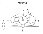
- FIGURE illustrates an example of the schematic construction of an electrophotographic apparatus including a process cartridge having the electrophotographic photosensitive member of the present invention.
- a cylindrical electrophotographic photosensitive member 1 is rotationally driven about an axis 2 in a direction indicated by an arrow at a predetermined peripheral speed.
- the surface of the electrophotographic photosensitive member 1 to be rotationally driven is uniformly charged to a positive or negative predetermined potential by charging unit (primary charging unit: a charging roller or the like) 3.
- charging unit primary charging unit: a charging roller or the like
- the surface receives exposure light (image exposure light) 4 output from exposing unit (not shown) such as slit exposure or laser beam scanning exposure.
- exposing unit not shown
- electrostatic latent images corresponding to a target image are sequentially formed on the surface of the electrophotographic photosensitive member 1.
- the electrostatic latent images formed on the surface of the electrophotographic photosensitive member 1 are developed with toners in the developers of developing unit 5 to provide toner images.
- the toner images formed and borne on the surface of the electrophotographic photosensitive member 1 are sequentially transferred onto a transfer material (such as paper) P by a transfer bias from transferring unit (such as a transfer roller) 6.
- a transfer bias from transferring unit such as a transfer roller
- the transfer material P is taken out of transfer material-supplying unit (not shown) and fed into a gap between the electrophotographic photosensitive member 1 and the transferring unit 6 (abutting portion) in synchronization with the rotation of the electrophotographic photosensitive member 1.
- the transfer material P onto which the toner images have been transferred is separated from the surface of the electrophotographic photosensitive member 1 and then introduced to fixing unit 8.
- the transfer material P is subjected to image fixation to be printed out as an image-formed product (print or copy) to the outside of the apparatus.
- the surface of the electrophotographic photosensitive member 1 after the transfer of the toner images is cleaned by removal of the remaining developer (toner) after the transfer by cleaning unit (such as cleaning blade) 7. Subsequently, the surface of the electrophotographic photosensitive member 1 is subjected to a neutralization process with pre-exposure light (not shown) from pre-exposing unit (not shown) and then repeatedly used in image formation.
- pre-exposure light not shown
- the charging unit 3, the developing unit 5, the transferring unit 6, and the cleaning unit 7, a plurality of them may be stored in a container and integrally supported to form a process cartridge.
- the process cartridge may be designed so as to be detachably mountable to the main body of an electrophotographic apparatus such as a copying machine or a laser beam printer.
- the charging unit 3, the developing unit 5, and the cleaning unit 7 are integrally supported with the electrophotographic photosensitive member 1 to provide a cartridge, and then the cartridge is used as a process cartridge 9 detachably mountable to the main body of the electrophotographic apparatus with a guiding unit 10 such as a rail of the main body of the electrophotographic apparatus.
- An emulsion containing a charge transporting substance and a resin was produced by the following method.
- the resultant emulsion was evaluated for its liquid stability as described below.
- the evaluation method after the production of the emulsion by the foregoing method, the emulsion was visually observed and then evaluated for the particle diameters of its emulsified particles. Further, the prepared emulsion was left to stand still for 2 weeks (under an environment having a temperature of 23°C and a humidity of 50%). The emulsion that had been left to stand still was stirred with a homogenizer PHYSCOTRON manufactured by MICROTEC CO., LTD. at 1,000 revolutions/min for 3 minutes. The state of the emulsion after the stirring was visually observed.
- the particle diameters of the emulsified particles were measured by measuring their average particle diameters before the standing and after the stirring with the homogenizer after the standing. It should be noted that, with regard to the measurement of the average particle diameters, the emulsion for a charge transporting layer was diluted with water and then the average particle diameter of the diluted liquid was measured with an ultracentrifugal, automatic particle size distribution measuring apparatus manufactured by HORIBA, Ltd. (CAPA700).
- Example 4 No significant change was found between the states of the emulsion obtained in Example 1 before and after the standing by visual observation. In addition, there was substantially no change between the average particle diameters before and after the standing. Accordingly, a stable emulsion was held. Table 4 shows the results of the evaluation. It should be noted that the evaluation by visual observation before and after the standing was performed in a state where the emulsion was charged into a cell measuring 1 cm by 1 cm after having been diluted with water twofold.
- Emulsions were each produced by the same method as that of Example 1 except that: the kinds and ratios of the charge transporting substances and the binder resin were changed as shown in Table 3; and the ratio of the hydrophobic organic solvent to the hydrophilic organic solvent and the kinds of the organic solvents, and the ratio of water to the organic solvents were changed as shown in Table 4.
- Table 4 shows the results of the evaluation of the resultant emulsions for their liquid stability.
- Table 4 shows the results of the evaluation of the resultant emulsions for their liquid stability.
- Table 4 shows the results of the evaluation of the resultant emulsions for their liquid stability.
- Table 4 shows the results of the evaluation of the resultant emulsions for their liquid stability.
- Emulsions were each produced by the same method as that of Example 1 except that: the kinds and ratios of the charge transporting substances and the binder resin were changed as shown in Table 3; the ratio of the hydrophobic organic solvent to the hydrophilic organic solvent and the kinds of the organic solvents, and the ratio of water to the organic solvents were changed as shown in Table 4; and a surfactant was added in an amount shown in Table 4 to water.
- Table 4 shows the results of the evaluation of the resultant emulsions for their liquid stability.
- the addition amount of the surfactant is represented as a ratio with respect to the entirety of an emulsion in a mass% unit.
- An application liquid containing a charge transporting substance and a binder resin was produced by the following method based on the method described in Patent Literature 1.
- the number of revolutions was increased to 7,000 revolutions/min and then the mixture was stirred for 20 minutes. After that, the mixture was emulsified with a high-pressure impact type disperser Nanomizer (manufactured by YOSHIDA KIKAI CO., LTD.) under a pressure condition of 150 MPa. Thus, an emulsion for a charge transporting layer (100 parts) was obtained.
- a high-pressure impact type disperser Nanomizer manufactured by YOSHIDA KIKAI CO., LTD.
- the emulsified application liquid for a charge transporting layer thus obtained was evaluated for its liquid stability.
- the emulsion for a charge transporting layer produced by the foregoing method was left to stand still for 2 weeks (under an environment having a temperature of 23°C and a humidity of 50%).
- the emulsion for a charge transporting layer that had been left to stand still was stirred with a homogenizer at 1,000 revolutions/min for 3 minutes.
- the state of the dispersion (emulsion) after the stirring with the homogenizer was visually observed.
- the average particle diameters of the emulsion before the standing and after the stirring with the homogenizer after the standing were measured by the same method as that of Example 1. Table 6 shows the results. It should be noted that the evaluation by visual observation before and after the standing was performed in a state where the emulsion was charged into a cell measuring 1 cm by 1 cm after having been diluted with water twofold.
- the emulsified application liquid for a charge transporting layer obtained in Comparative Example 1 after the standing was in such a state that the sedimentation of an oil droplet component was observed and an agglomerate was observed at a bottom surface owing to the coalescence of part of the oil droplet components.
- the emulsion for a charge transporting layer after the stirring could not form a state of an application liquid having high uniformity because the agglomeration of the oil droplet components was observed unlike the emulsion immediately after the production of the emulsion.
- An emulsion for a charge transporting layer was produced by the same method as that of Comparative Example 1 except that: the compound represented by the formula (1-3) was used as a charge transporting substance; and o-xylene was used as an organic solvent.
- the resultant emulsion for a charge transporting layer was evaluated for its stability by the same method as that of Comparative Example 1. Table 6 shows the results.
- An emulsion for a charge transporting layer was produced by the same method as that of Comparative Example 1 except that: the amount of toluene as the organic solvent was changed to 30 parts; and 58.5 parts of water were used.
- the resultant emulsion for a charge transporting layer was evaluated for its stability by the same method as that of Comparative Example 1. Table 6 shows the results.
- An emulsion for a charge transporting layer was produced by the same method as that of Comparative Example 2 except that: the amount of o-xylene as the organic solvent was changed to 30 parts; and 58.5 parts of water were used.
- the resultant emulsion for a charge transporting layer was evaluated for its stability by the same method as that of Comparative Example 1. Table 6 shows the results.
- An emulsion for a charge transporting layer was produced by the same method as that of Comparative Example 1 except that: 20 parts of toluene and 10 parts of dipropylene glycol monobutyl ether (whose solubility in water under 25°C and 1 atmosphere (atmospheric pressure) was 3.0 mass%) were used as organic solvents; and 58.5 parts of water were used.
- the resultant emulsion for a charge transporting layer was evaluated for its stability by the same method as that of Comparative Example 1. Table 6 shows the results.
- An emulsion for a charge transporting layer was produced by the same method as that of Comparative Example 8 except that diethylene glycol monophenyl ether (whose solubility in water under 25°C and 1 atmosphere (atmospheric pressure) was 3.4 mass%) was used instead of dipropylene glycol monobutyl ether used in Comparative Example 8.
- the resultant emulsion for a charge transporting layer was evaluated for its stability by the same method as that of Comparative Example 1. Table 6 shows the results.
- An emulsion for a charge transporting layer was produced by the same method as that of Comparative Example 8 except that 1,4-butanediol diacetate (whose solubility in water under 25°C and 1 atmosphere (atmospheric pressure) was 4.2 mass%) was used instead of dipropylene glycol monobutyl ether used in Comparative Example 8.
- the resultant emulsion for a charge transporting layer was evaluated for its stability by the same method as that of Comparative Example 1. Table 6 shows the results.
- Example 37 o-Xylene Tetrahydrofuran 9/1 6/4 0 mass% Uniform and semitransparent 1.8 ⁇ m Uniform and semitransparent 2.0 ⁇ m
- Example 38 Chloroform Dimethoxymethane 5/5 6/4 0 mass% Uniform and semitransparent 4.4 ⁇ m Uniform and semitransparent 4.6 ⁇ m
- Example 39 Chlorobenzene 1,4-Dioxane 6/4 7/3 0 mass% Uniform and semitransparent 2.6 ⁇ m Uniform and semitransparent 2.7 ⁇ m
- Example 40 Chlorobenzene 1,3,5-Trioxane 5/5 5/5 0 mass% Uniform and semitransparent 4.7 ⁇ m Uniform and semitransparent 4.8 ⁇ m
- Example 41 o-Dichlorobenzene Tetrahydrofuran 5/5 6/4 0 mass% Uniform and semitransparent 2.4 ⁇ m Uniform and semitransparent 2.7 ⁇ m
- Example 42 o-Dichlorobenzene Dime Dime
- Example 190 p-Xylene Propylene glycol n-butyl ether 7/3 6/4 1.0 mass% Uniform and semitransparent 5.8 ⁇ m Uniform and bluish white 6.1 ⁇ m
- Example 191 o-Xylene Propylene glycol monopropyl ether 7/3 6/4 1.0 mass% Uniform and semitransparent 2.5 ⁇ m Uniform and semitransparent 2.6 ⁇ m
- Example 192 Toluene Ethylene glycol monomethyl ether 7/3 6/4 1.0 mass% Uniform and semitransparent 2.5 ⁇ m Uniform and semitransparent 2.8 ⁇ m
- Example 193 p-Xylene Diethylene glycol monoethyl ether 7/3 5/5 1.0 mass% Uniform and semitransparent 2.2 ⁇ m Uniform and semitransparent 2.4 ⁇ m
- Example 194 Chlorobenzene Ethylene glycol monoisopropyl ether 5/5 6/4 1.0 mass% Uniform and semitransparent 2.5 ⁇ m Uniform and semitransparent
- the production method of the present invention including dissolving the charge transporting substance and the binder resin with a liquid containing both the first liquid that is hydrophobic and the second liquid that is hydrophilic, and mixing the solution with water to produce an emulsion for a charge transporting layer, an emulsified state is stably maintained even in a long-term storage state and hence an emulsion similar to that at an initial stage is obtained.
- the content of an organic solvent having a low affinity for water is preferably reduced in order that the coalescence of oil droplets in emulsified states may be suppressed.
- the concentration of each of the charge transporting substance and the binder resin in the organic solution is so high that a state where the emulsion is hard to form is established.
- a method involving increasing the content of the surfactant is also conceivable for suppressing the coalescence.
- the method is not preferred because the surfactant is generally liable to cause the deterioration of the characteristics of an electrophotographic photosensitive member.
- the second liquid as a hydrophilic liquid in an oil droplet quickly migrates toward an aqueous phase side and hence the oil droplet becomes additionally small, and the concentration of each of the charge transporting substance and the binder resin in the oil droplet increases.
- an emulsified particle adopts a form close to a fine particle of a solid and hence the occurrence of the agglomeration of oil droplets can be significantly suppressed as compared with that in the case where an emulsion is produced with the first liquid as a hydrophobic solvent alone.
- the content of the organic solvent (a halogen-based solvent or an aromatic solvent) in which the charge transporting substance and the binder resin in the emulsion for a charge transporting layer are highly soluble can be reduced, and the long-term liquid stability of the emulsion is good. Accordingly, the emulsion is useful as an application liquid for an electrophotographic photosensitive member.
- An aluminum cylinder having a diameter of 30 mm and a length of 260.5 mm was used as a support.
- 10 parts of SnO 2 -coated barium sulfate (conductive particle), 2 parts of titanium oxide (pigment for controlling resistance), 6 parts of a phenol resin, and 0.001 part of silicone oil (leveling agent) were used together with a mixed solvent of 4 parts of methanol and 16 parts of methoxypropanol, to thereby prepare an application liquid for the conductive layer.
- the application liquid for the conductive layer was applied onto the aluminum cylinder by dip coating and hardened (thermally hardened) at 140°C for 30 minutes, to thereby form an conductive layer having a thickness of 15 ⁇ m.
- hydroxygallium phthalocyanine charge generating substance having a crystal structure showing intense peaks at Bragg angles (2 ⁇ 0.2°) of 7.5°, 9.9°, 16.3°, 18.6°, 25.1°, and 28.3° in CuK ⁇ characteristic X-ray diffraction were prepared.
- hydroxygallium phthalocyanine charge generating substance
- To the hydroxygallium phthalocyanine were added 250 parts of cyclohexanone and 5 parts of a polyvinyl butyral (product name: S-LEC BX-1, manufactured by Sekisui Chemical Co., Ltd.), and the resultant mixture was dispersed by a sand mill apparatus using glass beads each having a diameter of 1 mm under a 23 ⁇ 3°C atmosphere for 1 hour.
- the application liquid for the charge generating layer was applied onto the intermediate layer by dip coating and dried at 100°C for 10 minutes, to thereby form a charge generating layer having a thickness of 0.26 ⁇ m.
- Example 7 shows the emulsion used and conditions for the heating of a coat obtained by applying the emulsion.
- the emulsion was left to stand still for 2 weeks (under a temperature of 23°C and a humidity of 50%) and then stirred with a homogenizer at 1,000 revolutions/min for 3 minutes before the emulsion was used in the dip coating.
- the surface of a position distant from an end portion of a photosensitive member by 130 mm was subjected to measurement with a surface roughness measuring instrument (SURFCORDER SE-3400 manufactured by Kosaka Laboratory Ltd.) and an evaluation in conformance with a ten-point average roughness (Rzjis) evaluation in JIS B 0601:2001 (evaluation length: 10 mm) was performed.
- Table 7 shows the results.
- a laser beam printer LBP-2510 manufactured by Canon Inc. was reconstructed so that, with regard to the charged potential (dark portion potential) of an electrophotographic photosensitive member and the exposure value (image exposure value) of a laser light source having a wavelength of 780 nm, a light quantity on the surface of the electrophotographic photosensitive member was 0.3 ⁇ J/cm 2 .
- the evaluation was performed under an environment having a temperature of 23°C and a relative humidity of 15%.
- Electrophotographic photosensitive members were each produced by the same method as that of Example 79 except that: an emulsion shown in Table 7 was used for a charge transporting layer; and conditions for the heating of a coat obtained by applying the emulsion were changed as shown in Table 7. The evaluations of the photosensitive members were also performed by the same methods as those of Example 79. Table 7 shows the results.
- An organic electroluminescence device was produced as described below.
- ITO was formed into a film having a thickness of 100 nm on a glass substrate as a support by a sputtering method.
- the resultant was subjected to ultrasonic washing with acetone and isopropyl alcohol (IPA) sequentially. After that, the resultant was subjected to boil washing with IPA and then dried. Further, the surface of the substrate was subjected to UV/ozone washing. Thus, an anode layer was obtained.
- IPA isopropyl alcohol
- the number of revolutions of the homogenizer was increased to 5,000 revolutions/min and then the mixture was stirred for 10 minutes. After that, the mixture was subjected to dispersion with a highpressure impact type disperser Nanomizer (manufactured by YOSHIDA KIKAI CO., LTD.) under a pressure condition of 150 MPa. Thus, an emulsion for a charge transporting layer (100 parts) was obtained.
- a highpressure impact type disperser Nanomizer manufactured by YOSHIDA KIKAI CO., LTD.
- the emulsion for a charge transporting layer was applied onto the anode layer by spin coating at 3,000 revolutions/min for 30 seconds so that a film having a thickness of 50 nm was obtained. Thus, a charge transporting layer was formed.
- an electron injecting layer having a thickness of 15 nm was formed by co-depositing bathophenanthroline and cesium carbonate from the vapor so that the concentration of cesium in the layer was 8.3 mass%.
- silver (Ag) was formed into a film on the layer by a heating deposition method.
- a cathode layer having a thickness of 12 nm was formed.
- a voltage of 6 V was applied between the anode layer and the cathode layer. As a result, it was confirmed that the device emitted light at 8,000 Cd/cm 2 .
- An organic electroluminescence device was produced by the same method as that of Example 157 except that N,N-di(naphthalene-1-yl)-N,N-diphenylbenzidine (NPB) as a charge transporting substance was used instead of the compound (1-5) in Example 157.
- NPB N,N-di(naphthalene-1-yl)-N,N-diphenylbenzidine
- a voltage of 6 V was applied between the anode layer and the cathode layer. As a result, it was confirmed that the device emitted light at 9,000 Cd/cm 2 .
- Electrophotographic photosensitive members were each produced by the same method as that of Example 79 except that: an emulsion shown in Table 8 was used for a charge transporting layer; and conditions for the heating of a coat obtained by applying the emulsion were changed as shown in Table 8.
- the evaluations of the photosensitive members were also performed by the same methods as those of Example 79. Table 8 shows the results. Gentle irregularities were formed in each of the resultant electrophotographic photosensitive members and image unevenness corresponding to the irregularities was detected as an image.
- Electrophotographic photosensitive members were each produced by the same method as that of Example 79 except that: a produced emulsion for a charge transporting layer was immediately used in dip coating without being left to stand still for 2 weeks; an emulsion shown in Table 8 was used; and conditions for the heating of a coat obtained by applying the emulsion were changed as shown in Table 8.
- the evaluations of the photosensitive members were also performed by the same methods as those of Example 79. Table 8 shows the results. Gentle irregularities were formed in each of the resultant electrophotographic photosensitive members and image unevenness corresponding to the irregularities was detected as an image.
- Electrophotographic photosensitive members were each produced by the same method as that of Example 79 except that: an emulsion shown in Table 8 was used for a charge transporting layer; and conditions for the heating of a coat obtained by applying the emulsion were changed as shown in Table 8.
- the evaluations of the photosensitive members were also performed by the same methods as those of Example 79. Table 8 shows the results. Gentle irregularities were formed in each of the resultant electrophotographic photosensitive members and image unevenness corresponding to the irregularities was detected as an image.
- Example 1 130°C 60 minutes 0.55 ⁇ m A
- Example 80 Example 2 130°C 60 minutes 0.52 ⁇ m A
- Example 81 Example 3 130°C 60 minutes 0.53 ⁇ m A
- Example 82 Example 4 130°C 60 minutes 0.55 ⁇ m A
- Example 83 Example 5 130°C 60 minutes 0.51 ⁇ m A
- Example 84 Example 6 130°C 60 minutes 0.58 ⁇ m A
- Example 85 Example 7 130°C 60 minutes 0.63 ⁇ m B
- Example 86 130°C 60 minutes 0.57 ⁇ m A
- Example 87 Example 9 130°C 60 minutes 0.63 ⁇ m B
- Example 88 Example 10 130°C 60 minutes 0.57 ⁇ m A
- Example 89 Example 11 130°C 60 minutes 0.58 ⁇ m A
- Example 90 Example 12 130°C 60 minutes 0.68 ⁇ m B
- Example 91 Example 13 130°C 60 minutes 0.67 ⁇ m B
- Example 92 Example 14 130°C 60 minutes 0.63 ⁇ m B
- Example 93 Example 15 150°C 60 minutes
- the emulsion formed only of the first liquid having the construction described in Patent Literature 1 was poor in uniformity of a coat when the coat was formed with the emulsion that had been left to stand still for a long time period. This may be because of the following reason.
- the agglomeration of oil droplets occurred owing to the coalescence of the oil droplets after the long-term storage of the emulsion to impair the uniformity of an oil droplet in the emulsion, with the result that the uniformity of the surface of the coat after the formation of the coat deteriorated.
- increasing the heating temperature for the coat to a temperature higher than the melting point of the charge transporting substance does not lead to the acquisition of sufficient coat uniformity, though the increase shows an improvement in coat uniformity.
- the emulsion formed only of the first liquid may be unable to provide sufficient coat uniformity as compared with that of the emulsion of the present invention containing both the first liquid and the second liquid even when the emulsion is not stored for a long time period.
Landscapes
- Physics & Mathematics (AREA)
- General Physics & Mathematics (AREA)
- Chemical & Material Sciences (AREA)
- Chemical Kinetics & Catalysis (AREA)
- Spectroscopy & Molecular Physics (AREA)
- Engineering & Computer Science (AREA)
- Manufacturing & Machinery (AREA)
- Photoreceptors In Electrophotography (AREA)
- Electroluminescent Light Sources (AREA)
Applications Claiming Priority (3)
| Application Number | Priority Date | Filing Date | Title |
|---|---|---|---|
| JP2011282083 | 2011-12-22 | ||
| JP2012267389A JP6040018B2 (ja) | 2011-12-22 | 2012-12-06 | 電子写真感光体の製造方法、有機デバイスの製造方法、および電荷輸送層用乳化液 |
| PCT/JP2012/082600 WO2013094548A1 (en) | 2011-12-22 | 2012-12-11 | Method of producing electrophotographic photosensitive member, method of producing organic device, and emulsion for charge transporting layer |
Publications (3)
| Publication Number | Publication Date |
|---|---|
| EP2795404A1 EP2795404A1 (en) | 2014-10-29 |
| EP2795404A4 EP2795404A4 (en) | 2015-08-12 |
| EP2795404B1 true EP2795404B1 (en) | 2016-09-14 |
Family
ID=48668438
Family Applications (1)
| Application Number | Title | Priority Date | Filing Date |
|---|---|---|---|
| EP12860113.5A Not-in-force EP2795404B1 (en) | 2011-12-22 | 2012-12-11 | Method of producing electrophotographic photosensitive member, method of producing organic device, and emulsion for charge transporting layer |
Country Status (5)
| Country | Link |
|---|---|
| US (1) | US9575422B2 (enExample) |
| EP (1) | EP2795404B1 (enExample) |
| JP (1) | JP6040018B2 (enExample) |
| CN (1) | CN103988129B (enExample) |
| WO (1) | WO2013094548A1 (enExample) |
Families Citing this family (22)
| Publication number | Priority date | Publication date | Assignee | Title |
|---|---|---|---|---|
| JP6105974B2 (ja) | 2012-03-15 | 2017-03-29 | キヤノン株式会社 | 電子写真感光体の製造方法、および電荷輸送層用乳化液 |
| JP6588731B2 (ja) | 2015-05-07 | 2019-10-09 | キヤノン株式会社 | 電子写真感光体、プロセスカートリッジおよび電子写真装置 |
| JP6639256B2 (ja) | 2016-02-10 | 2020-02-05 | キヤノン株式会社 | 電子写真装置、およびプロセスカートリッジ |
| JP7057104B2 (ja) | 2017-11-24 | 2022-04-19 | キヤノン株式会社 | プロセスカートリッジ及び電子写真画像形成装置 |
| JP7046571B2 (ja) | 2017-11-24 | 2022-04-04 | キヤノン株式会社 | プロセスカートリッジ及び電子写真装置 |
| JP7187270B2 (ja) | 2017-11-24 | 2022-12-12 | キヤノン株式会社 | プロセスカートリッジ及び電子写真装置 |
| JP7034769B2 (ja) | 2018-02-28 | 2022-03-14 | キヤノン株式会社 | 電子写真感光体、プロセスカートリッジ及び電子写真装置 |
| JP2019152699A (ja) | 2018-02-28 | 2019-09-12 | キヤノン株式会社 | 電子写真感光体、プロセスカートリッジ及び電子写真装置 |
| JP7034768B2 (ja) | 2018-02-28 | 2022-03-14 | キヤノン株式会社 | プロセスカートリッジ及び画像形成装置 |
| US10747130B2 (en) | 2018-05-31 | 2020-08-18 | Canon Kabushiki Kaisha | Process cartridge and electrophotographic apparatus |
| JP7059111B2 (ja) | 2018-05-31 | 2022-04-25 | キヤノン株式会社 | 電子写真感光体およびその製造方法、並びにプロセスカートリッジおよび電子写真画像形成装置 |
| JP7129225B2 (ja) | 2018-05-31 | 2022-09-01 | キヤノン株式会社 | 電子写真感光体および電子写真感光体の製造方法 |
| JP7059112B2 (ja) | 2018-05-31 | 2022-04-25 | キヤノン株式会社 | 電子写真感光体、プロセスカートリッジおよび電子写真画像形成装置 |
| JP7054366B2 (ja) | 2018-05-31 | 2022-04-13 | キヤノン株式会社 | 電子写真感光体、プロセスカートリッジおよび電子写真装置 |
| JP7150485B2 (ja) | 2018-05-31 | 2022-10-11 | キヤノン株式会社 | 電子写真感光体、プロセスカートリッジ及び電子写真装置 |
| JP7413054B2 (ja) | 2019-02-14 | 2024-01-15 | キヤノン株式会社 | 電子写真感光体、プロセスカートリッジおよび電子写真装置 |
| US11320754B2 (en) | 2019-07-25 | 2022-05-03 | Canon Kabushiki Kaisha | Process cartridge and electrophotographic apparatus |
| US11573499B2 (en) | 2019-07-25 | 2023-02-07 | Canon Kabushiki Kaisha | Process cartridge and electrophotographic apparatus |
| JP7337649B2 (ja) | 2019-10-18 | 2023-09-04 | キヤノン株式会社 | プロセスカートリッジ及び電子写真装置 |
| JP7337652B2 (ja) | 2019-10-18 | 2023-09-04 | キヤノン株式会社 | プロセスカートリッジ及びそれを用いた電子写真装置 |
| US11372351B2 (en) | 2020-09-14 | 2022-06-28 | Canon Kabushiki Kaisha | Electrophotographic member and electrophotographic image forming apparatus |
| JP2023134210A (ja) | 2022-03-14 | 2023-09-27 | キヤノン株式会社 | プロセスカートリッジ及び電子写真装置 |
Family Cites Families (12)
| Publication number | Priority date | Publication date | Assignee | Title |
|---|---|---|---|---|
| US553182A (en) | 1896-01-14 | Richard wegner | ||
| JPH07313915A (ja) * | 1994-05-26 | 1995-12-05 | Fuji Xerox Co Ltd | 塗布方法および塗布装置 |
| US5531872A (en) | 1994-08-11 | 1996-07-02 | Xerox Corporation | Processes for preparing photoconductive members by electrophoresis |
| JP4770125B2 (ja) * | 2004-04-16 | 2011-09-14 | 凸版印刷株式会社 | 印刷インキ、およびこれを用いた高分子el素子の製造方法 |
| JP4847245B2 (ja) | 2005-08-15 | 2011-12-28 | キヤノン株式会社 | 電子写真感光体、プロセスカートリッジおよび電子写真装置 |
| JP2007087847A (ja) * | 2005-09-26 | 2007-04-05 | Seiko Epson Corp | 有機半導体素子の製造方法、有機半導体素子、有機半導体装置および電子機器 |
| EP2397908B1 (en) * | 2006-10-31 | 2016-04-27 | Canon Kabushiki Kaisha | Electrophotographic photosensitive member, method of manufacturing electrophotographic photosensitive member, process cartridge, and electrophotographic apparatus |
| JP4235673B2 (ja) | 2007-07-17 | 2009-03-11 | キヤノン株式会社 | 電子写真感光体の製造方法 |
| JP2009288401A (ja) * | 2008-05-28 | 2009-12-10 | Konica Minolta Business Technologies Inc | 電子写真感光体の製造方法、電子写真感光体 |
| US8273514B2 (en) | 2009-05-22 | 2012-09-25 | Xerox Corporation | Interfacial layer and coating solution for forming the same |
| JP2011128213A (ja) * | 2009-12-15 | 2011-06-30 | Sharp Corp | 電子写真感光体およびそれを備えた画像形成装置 |
| JP6105974B2 (ja) | 2012-03-15 | 2017-03-29 | キヤノン株式会社 | 電子写真感光体の製造方法、および電荷輸送層用乳化液 |
-
2012
- 2012-12-06 JP JP2012267389A patent/JP6040018B2/ja active Active
- 2012-12-11 CN CN201280060894.2A patent/CN103988129B/zh active Active
- 2012-12-11 EP EP12860113.5A patent/EP2795404B1/en not_active Not-in-force
- 2012-12-11 US US14/353,463 patent/US9575422B2/en active Active
- 2012-12-11 WO PCT/JP2012/082600 patent/WO2013094548A1/en not_active Ceased
Also Published As
| Publication number | Publication date |
|---|---|
| US20140315124A1 (en) | 2014-10-23 |
| EP2795404A4 (en) | 2015-08-12 |
| CN103988129B (zh) | 2017-10-03 |
| JP2013148877A (ja) | 2013-08-01 |
| CN103988129A (zh) | 2014-08-13 |
| WO2013094548A1 (en) | 2013-06-27 |
| JP6040018B2 (ja) | 2016-12-07 |
| US9575422B2 (en) | 2017-02-21 |
| EP2795404A1 (en) | 2014-10-29 |
Similar Documents
| Publication | Publication Date | Title |
|---|---|---|
| EP2795404B1 (en) | Method of producing electrophotographic photosensitive member, method of producing organic device, and emulsion for charge transporting layer | |
| JP6049417B2 (ja) | 電荷輸送層を有する電子写真感光体および有機デバイスの製造方法 | |
| JP6105973B2 (ja) | 電子写真感光体の製造方法、電荷輸送層用乳化液 | |
| EP2795403B1 (en) | Process for producing electrophotographic photosensitive member | |
| JP6105974B2 (ja) | 電子写真感光体の製造方法、および電荷輸送層用乳化液 | |
| EP2816413B1 (en) | Process for producing electrophotographic photosensitive member | |
| JP6161425B2 (ja) | 電子写真感光体の製造方法 | |
| CN104950605B (zh) | 电子照相感光构件、电子照相感光构件的生产方法、处理盒和电子照相设备 | |
| CN103713484A (zh) | 电子照相感光构件、处理盒和电子照相设备 | |
| JP6071726B2 (ja) | 電子写真感光体の製造方法 |
Legal Events
| Date | Code | Title | Description |
|---|---|---|---|
| PUAI | Public reference made under article 153(3) epc to a published international application that has entered the european phase |
Free format text: ORIGINAL CODE: 0009012 |
|
| 17P | Request for examination filed |
Effective date: 20140722 |
|
| AK | Designated contracting states |
Kind code of ref document: A1 Designated state(s): AL AT BE BG CH CY CZ DE DK EE ES FI FR GB GR HR HU IE IS IT LI LT LU LV MC MK MT NL NO PL PT RO RS SE SI SK SM TR |
|
| DAX | Request for extension of the european patent (deleted) | ||
| RA4 | Supplementary search report drawn up and despatched (corrected) |
Effective date: 20150714 |
|
| RIC1 | Information provided on ipc code assigned before grant |
Ipc: G03G 5/06 20060101ALI20150708BHEP Ipc: G03G 5/05 20060101ALI20150708BHEP Ipc: G03G 5/04 20060101ALI20150708BHEP Ipc: H05B 33/10 20060101ALI20150708BHEP Ipc: G03G 5/00 20060101AFI20150708BHEP Ipc: G03G 5/047 20060101ALI20150708BHEP Ipc: G03G 5/147 20060101ALI20150708BHEP Ipc: C09K 11/06 20060101ALI20150708BHEP |
|
| GRAP | Despatch of communication of intention to grant a patent |
Free format text: ORIGINAL CODE: EPIDOSNIGR1 |
|
| INTG | Intention to grant announced |
Effective date: 20160330 |
|
| GRAS | Grant fee paid |
Free format text: ORIGINAL CODE: EPIDOSNIGR3 |
|
| GRAA | (expected) grant |
Free format text: ORIGINAL CODE: 0009210 |
|
| AK | Designated contracting states |
Kind code of ref document: B1 Designated state(s): AL AT BE BG CH CY CZ DE DK EE ES FI FR GB GR HR HU IE IS IT LI LT LU LV MC MK MT NL NO PL PT RO RS SE SI SK SM TR |
|
| REG | Reference to a national code |
Ref country code: GB Ref legal event code: FG4D |
|
| REG | Reference to a national code |
Ref country code: CH Ref legal event code: EP |
|
| REG | Reference to a national code |
Ref country code: IE Ref legal event code: FG4D |
|
| REG | Reference to a national code |
Ref country code: AT Ref legal event code: REF Ref document number: 829639 Country of ref document: AT Kind code of ref document: T Effective date: 20161015 |
|
| REG | Reference to a national code |
Ref country code: DE Ref legal event code: R096 Ref document number: 602012023163 Country of ref document: DE |
|
| REG | Reference to a national code |
Ref country code: LT Ref legal event code: MG4D |
|
| REG | Reference to a national code |
Ref country code: NL Ref legal event code: MP Effective date: 20160914 |
|
| PG25 | Lapsed in a contracting state [announced via postgrant information from national office to epo] |
Ref country code: LT Free format text: LAPSE BECAUSE OF FAILURE TO SUBMIT A TRANSLATION OF THE DESCRIPTION OR TO PAY THE FEE WITHIN THE PRESCRIBED TIME-LIMIT Effective date: 20160914 Ref country code: FI Free format text: LAPSE BECAUSE OF FAILURE TO SUBMIT A TRANSLATION OF THE DESCRIPTION OR TO PAY THE FEE WITHIN THE PRESCRIBED TIME-LIMIT Effective date: 20160914 Ref country code: NO Free format text: LAPSE BECAUSE OF FAILURE TO SUBMIT A TRANSLATION OF THE DESCRIPTION OR TO PAY THE FEE WITHIN THE PRESCRIBED TIME-LIMIT Effective date: 20161214 Ref country code: HR Free format text: LAPSE BECAUSE OF FAILURE TO SUBMIT A TRANSLATION OF THE DESCRIPTION OR TO PAY THE FEE WITHIN THE PRESCRIBED TIME-LIMIT Effective date: 20160914 Ref country code: RS Free format text: LAPSE BECAUSE OF FAILURE TO SUBMIT A TRANSLATION OF THE DESCRIPTION OR TO PAY THE FEE WITHIN THE PRESCRIBED TIME-LIMIT Effective date: 20160914 |
|
| REG | Reference to a national code |
Ref country code: AT Ref legal event code: MK05 Ref document number: 829639 Country of ref document: AT Kind code of ref document: T Effective date: 20160914 |
|
| PG25 | Lapsed in a contracting state [announced via postgrant information from national office to epo] |
Ref country code: GR Free format text: LAPSE BECAUSE OF FAILURE TO SUBMIT A TRANSLATION OF THE DESCRIPTION OR TO PAY THE FEE WITHIN THE PRESCRIBED TIME-LIMIT Effective date: 20161215 Ref country code: NL Free format text: LAPSE BECAUSE OF FAILURE TO SUBMIT A TRANSLATION OF THE DESCRIPTION OR TO PAY THE FEE WITHIN THE PRESCRIBED TIME-LIMIT Effective date: 20160914 Ref country code: LV Free format text: LAPSE BECAUSE OF FAILURE TO SUBMIT A TRANSLATION OF THE DESCRIPTION OR TO PAY THE FEE WITHIN THE PRESCRIBED TIME-LIMIT Effective date: 20160914 Ref country code: SE Free format text: LAPSE BECAUSE OF FAILURE TO SUBMIT A TRANSLATION OF THE DESCRIPTION OR TO PAY THE FEE WITHIN THE PRESCRIBED TIME-LIMIT Effective date: 20160914 |
|
| PG25 | Lapsed in a contracting state [announced via postgrant information from national office to epo] |
Ref country code: EE Free format text: LAPSE BECAUSE OF FAILURE TO SUBMIT A TRANSLATION OF THE DESCRIPTION OR TO PAY THE FEE WITHIN THE PRESCRIBED TIME-LIMIT Effective date: 20160914 Ref country code: RO Free format text: LAPSE BECAUSE OF FAILURE TO SUBMIT A TRANSLATION OF THE DESCRIPTION OR TO PAY THE FEE WITHIN THE PRESCRIBED TIME-LIMIT Effective date: 20160914 |
|
| PG25 | Lapsed in a contracting state [announced via postgrant information from national office to epo] |
Ref country code: IS Free format text: LAPSE BECAUSE OF FAILURE TO SUBMIT A TRANSLATION OF THE DESCRIPTION OR TO PAY THE FEE WITHIN THE PRESCRIBED TIME-LIMIT Effective date: 20170114 Ref country code: PT Free format text: LAPSE BECAUSE OF FAILURE TO SUBMIT A TRANSLATION OF THE DESCRIPTION OR TO PAY THE FEE WITHIN THE PRESCRIBED TIME-LIMIT Effective date: 20170116 Ref country code: ES Free format text: LAPSE BECAUSE OF FAILURE TO SUBMIT A TRANSLATION OF THE DESCRIPTION OR TO PAY THE FEE WITHIN THE PRESCRIBED TIME-LIMIT Effective date: 20160914 Ref country code: AT Free format text: LAPSE BECAUSE OF FAILURE TO SUBMIT A TRANSLATION OF THE DESCRIPTION OR TO PAY THE FEE WITHIN THE PRESCRIBED TIME-LIMIT Effective date: 20160914 Ref country code: SK Free format text: LAPSE BECAUSE OF FAILURE TO SUBMIT A TRANSLATION OF THE DESCRIPTION OR TO PAY THE FEE WITHIN THE PRESCRIBED TIME-LIMIT Effective date: 20160914 Ref country code: SM Free format text: LAPSE BECAUSE OF FAILURE TO SUBMIT A TRANSLATION OF THE DESCRIPTION OR TO PAY THE FEE WITHIN THE PRESCRIBED TIME-LIMIT Effective date: 20160914 Ref country code: CZ Free format text: LAPSE BECAUSE OF FAILURE TO SUBMIT A TRANSLATION OF THE DESCRIPTION OR TO PAY THE FEE WITHIN THE PRESCRIBED TIME-LIMIT Effective date: 20160914 Ref country code: PL Free format text: LAPSE BECAUSE OF FAILURE TO SUBMIT A TRANSLATION OF THE DESCRIPTION OR TO PAY THE FEE WITHIN THE PRESCRIBED TIME-LIMIT Effective date: 20160914 Ref country code: BG Free format text: LAPSE BECAUSE OF FAILURE TO SUBMIT A TRANSLATION OF THE DESCRIPTION OR TO PAY THE FEE WITHIN THE PRESCRIBED TIME-LIMIT Effective date: 20161214 Ref country code: BE Free format text: LAPSE BECAUSE OF FAILURE TO SUBMIT A TRANSLATION OF THE DESCRIPTION OR TO PAY THE FEE WITHIN THE PRESCRIBED TIME-LIMIT Effective date: 20160914 |
|
| REG | Reference to a national code |
Ref country code: DE Ref legal event code: R097 Ref document number: 602012023163 Country of ref document: DE |
|
| PG25 | Lapsed in a contracting state [announced via postgrant information from national office to epo] |
Ref country code: IT Free format text: LAPSE BECAUSE OF FAILURE TO SUBMIT A TRANSLATION OF THE DESCRIPTION OR TO PAY THE FEE WITHIN THE PRESCRIBED TIME-LIMIT Effective date: 20160914 |
|
| PLBE | No opposition filed within time limit |
Free format text: ORIGINAL CODE: 0009261 |
|
| STAA | Information on the status of an ep patent application or granted ep patent |
Free format text: STATUS: NO OPPOSITION FILED WITHIN TIME LIMIT |
|
| PG25 | Lapsed in a contracting state [announced via postgrant information from national office to epo] |
Ref country code: DK Free format text: LAPSE BECAUSE OF FAILURE TO SUBMIT A TRANSLATION OF THE DESCRIPTION OR TO PAY THE FEE WITHIN THE PRESCRIBED TIME-LIMIT Effective date: 20160914 |
|
| REG | Reference to a national code |
Ref country code: CH Ref legal event code: PL |
|
| 26N | No opposition filed |
Effective date: 20170615 |
|
| GBPC | Gb: european patent ceased through non-payment of renewal fee |
Effective date: 20161214 |
|
| PG25 | Lapsed in a contracting state [announced via postgrant information from national office to epo] |
Ref country code: MC Free format text: LAPSE BECAUSE OF FAILURE TO SUBMIT A TRANSLATION OF THE DESCRIPTION OR TO PAY THE FEE WITHIN THE PRESCRIBED TIME-LIMIT Effective date: 20160914 |
|
| REG | Reference to a national code |
Ref country code: FR Ref legal event code: ST Effective date: 20170831 |
|
| REG | Reference to a national code |
Ref country code: IE Ref legal event code: MM4A |
|
| PG25 | Lapsed in a contracting state [announced via postgrant information from national office to epo] |
Ref country code: CH Free format text: LAPSE BECAUSE OF NON-PAYMENT OF DUE FEES Effective date: 20161231 Ref country code: LI Free format text: LAPSE BECAUSE OF NON-PAYMENT OF DUE FEES Effective date: 20161231 Ref country code: FR Free format text: LAPSE BECAUSE OF NON-PAYMENT OF DUE FEES Effective date: 20170102 Ref country code: LU Free format text: LAPSE BECAUSE OF NON-PAYMENT OF DUE FEES Effective date: 20161211 |
|
| PG25 | Lapsed in a contracting state [announced via postgrant information from national office to epo] |
Ref country code: IE Free format text: LAPSE BECAUSE OF NON-PAYMENT OF DUE FEES Effective date: 20161211 Ref country code: GB Free format text: LAPSE BECAUSE OF NON-PAYMENT OF DUE FEES Effective date: 20161214 Ref country code: SI Free format text: LAPSE BECAUSE OF FAILURE TO SUBMIT A TRANSLATION OF THE DESCRIPTION OR TO PAY THE FEE WITHIN THE PRESCRIBED TIME-LIMIT Effective date: 20160914 |
|
| PG25 | Lapsed in a contracting state [announced via postgrant information from national office to epo] |
Ref country code: HU Free format text: LAPSE BECAUSE OF FAILURE TO SUBMIT A TRANSLATION OF THE DESCRIPTION OR TO PAY THE FEE WITHIN THE PRESCRIBED TIME-LIMIT; INVALID AB INITIO Effective date: 20121211 |
|
| PG25 | Lapsed in a contracting state [announced via postgrant information from national office to epo] |
Ref country code: MK Free format text: LAPSE BECAUSE OF FAILURE TO SUBMIT A TRANSLATION OF THE DESCRIPTION OR TO PAY THE FEE WITHIN THE PRESCRIBED TIME-LIMIT Effective date: 20160914 Ref country code: CY Free format text: LAPSE BECAUSE OF FAILURE TO SUBMIT A TRANSLATION OF THE DESCRIPTION OR TO PAY THE FEE WITHIN THE PRESCRIBED TIME-LIMIT Effective date: 20160914 |
|
| PG25 | Lapsed in a contracting state [announced via postgrant information from national office to epo] |
Ref country code: MT Free format text: LAPSE BECAUSE OF NON-PAYMENT OF DUE FEES Effective date: 20161211 |
|
| PG25 | Lapsed in a contracting state [announced via postgrant information from national office to epo] |
Ref country code: TR Free format text: LAPSE BECAUSE OF FAILURE TO SUBMIT A TRANSLATION OF THE DESCRIPTION OR TO PAY THE FEE WITHIN THE PRESCRIBED TIME-LIMIT Effective date: 20160914 Ref country code: AL Free format text: LAPSE BECAUSE OF FAILURE TO SUBMIT A TRANSLATION OF THE DESCRIPTION OR TO PAY THE FEE WITHIN THE PRESCRIBED TIME-LIMIT Effective date: 20160914 |
|
| PGFP | Annual fee paid to national office [announced via postgrant information from national office to epo] |
Ref country code: DE Payment date: 20211117 Year of fee payment: 10 |
|
| REG | Reference to a national code |
Ref country code: DE Ref legal event code: R119 Ref document number: 602012023163 Country of ref document: DE |
|
| PG25 | Lapsed in a contracting state [announced via postgrant information from national office to epo] |
Ref country code: DE Free format text: LAPSE BECAUSE OF NON-PAYMENT OF DUE FEES Effective date: 20230701 |