EP2790274B1 - Connecteur étanche et son procédé de fabrication - Google Patents
Connecteur étanche et son procédé de fabrication Download PDFInfo
- Publication number
- EP2790274B1 EP2790274B1 EP14163215.8A EP14163215A EP2790274B1 EP 2790274 B1 EP2790274 B1 EP 2790274B1 EP 14163215 A EP14163215 A EP 14163215A EP 2790274 B1 EP2790274 B1 EP 2790274B1
- Authority
- EP
- European Patent Office
- Prior art keywords
- contact
- shell
- waterproof
- housing
- connector
- Prior art date
- Legal status (The legal status is an assumption and is not a legal conclusion. Google has not performed a legal analysis and makes no representation as to the accuracy of the status listed.)
- Active
Links
- 238000004519 manufacturing process Methods 0.000 title claims description 33
- 238000000465 moulding Methods 0.000 claims description 31
- 230000003014 reinforcing effect Effects 0.000 claims description 30
- 238000003780 insertion Methods 0.000 claims description 29
- 230000037431 insertion Effects 0.000 claims description 29
- 239000002184 metal Substances 0.000 claims description 27
- 239000013013 elastic material Substances 0.000 claims description 16
- 239000000463 material Substances 0.000 claims description 16
- 239000011347 resin Substances 0.000 claims description 9
- 229920005989 resin Polymers 0.000 claims description 9
- 239000004020 conductor Substances 0.000 claims description 4
- 238000000034 method Methods 0.000 claims description 4
- 229920002379 silicone rubber Polymers 0.000 claims description 4
- 238000009413 insulation Methods 0.000 claims description 3
- 239000004945 silicone rubber Substances 0.000 claims 2
- 239000000758 substrate Substances 0.000 description 12
- 238000005192 partition Methods 0.000 description 11
- XLYOFNOQVPJJNP-UHFFFAOYSA-N water Substances O XLYOFNOQVPJJNP-UHFFFAOYSA-N 0.000 description 9
- 230000005611 electricity Effects 0.000 description 6
- 238000005452 bending Methods 0.000 description 5
- 230000010354 integration Effects 0.000 description 4
- 230000003068 static effect Effects 0.000 description 4
- 229920001971 elastomer Polymers 0.000 description 3
- 238000003825 pressing Methods 0.000 description 3
- 239000000853 adhesive Substances 0.000 description 2
- 230000001070 adhesive effect Effects 0.000 description 2
- 230000015572 biosynthetic process Effects 0.000 description 2
- 239000000470 constituent Substances 0.000 description 2
- 238000001764 infiltration Methods 0.000 description 2
- 230000008595 infiltration Effects 0.000 description 2
- 238000012856 packing Methods 0.000 description 2
- 230000000717 retained effect Effects 0.000 description 2
- 238000004078 waterproofing Methods 0.000 description 2
- 229920002799 BoPET Polymers 0.000 description 1
- 239000005041 Mylar™ Substances 0.000 description 1
- 230000006835 compression Effects 0.000 description 1
- 238000007906 compression Methods 0.000 description 1
- 238000007796 conventional method Methods 0.000 description 1
- 230000000694 effects Effects 0.000 description 1
- 238000002474 experimental method Methods 0.000 description 1
- 238000004080 punching Methods 0.000 description 1
- 238000007789 sealing Methods 0.000 description 1
- 238000005728 strengthening Methods 0.000 description 1
Images


Classifications
-
- H—ELECTRICITY
- H01—ELECTRIC ELEMENTS
- H01R—ELECTRICALLY-CONDUCTIVE CONNECTIONS; STRUCTURAL ASSOCIATIONS OF A PLURALITY OF MUTUALLY-INSULATED ELECTRICAL CONNECTING ELEMENTS; COUPLING DEVICES; CURRENT COLLECTORS
- H01R13/00—Details of coupling devices of the kinds covered by groups H01R12/70 or H01R24/00 - H01R33/00
- H01R13/46—Bases; Cases
- H01R13/52—Dustproof, splashproof, drip-proof, waterproof, or flameproof cases
- H01R13/5202—Sealing means between parts of housing or between housing part and a wall, e.g. sealing rings
-
- B—PERFORMING OPERATIONS; TRANSPORTING
- B29—WORKING OF PLASTICS; WORKING OF SUBSTANCES IN A PLASTIC STATE IN GENERAL
- B29C—SHAPING OR JOINING OF PLASTICS; SHAPING OF MATERIAL IN A PLASTIC STATE, NOT OTHERWISE PROVIDED FOR; AFTER-TREATMENT OF THE SHAPED PRODUCTS, e.g. REPAIRING
- B29C70/00—Shaping composites, i.e. plastics material comprising reinforcements, fillers or preformed parts, e.g. inserts
- B29C70/68—Shaping composites, i.e. plastics material comprising reinforcements, fillers or preformed parts, e.g. inserts by incorporating or moulding on preformed parts, e.g. inserts or layers, e.g. foam blocks
- B29C70/72—Encapsulating inserts having non-encapsulated projections, e.g. extremities or terminal portions of electrical components
-
- H—ELECTRICITY
- H01—ELECTRIC ELEMENTS
- H01R—ELECTRICALLY-CONDUCTIVE CONNECTIONS; STRUCTURAL ASSOCIATIONS OF A PLURALITY OF MUTUALLY-INSULATED ELECTRICAL CONNECTING ELEMENTS; COUPLING DEVICES; CURRENT COLLECTORS
- H01R43/00—Apparatus or processes specially adapted for manufacturing, assembling, maintaining, or repairing of line connectors or current collectors or for joining electric conductors
- H01R43/005—Apparatus or processes specially adapted for manufacturing, assembling, maintaining, or repairing of line connectors or current collectors or for joining electric conductors for making dustproof, splashproof, drip-proof, waterproof, or flameproof connection, coupling, or casing
-
- H—ELECTRICITY
- H01—ELECTRIC ELEMENTS
- H01R—ELECTRICALLY-CONDUCTIVE CONNECTIONS; STRUCTURAL ASSOCIATIONS OF A PLURALITY OF MUTUALLY-INSULATED ELECTRICAL CONNECTING ELEMENTS; COUPLING DEVICES; CURRENT COLLECTORS
- H01R43/00—Apparatus or processes specially adapted for manufacturing, assembling, maintaining, or repairing of line connectors or current collectors or for joining electric conductors
- H01R43/20—Apparatus or processes specially adapted for manufacturing, assembling, maintaining, or repairing of line connectors or current collectors or for joining electric conductors for assembling or disassembling contact members with insulating base, case or sleeve
- H01R43/24—Assembling by moulding on contact members
-
- H—ELECTRICITY
- H01—ELECTRIC ELEMENTS
- H01R—ELECTRICALLY-CONDUCTIVE CONNECTIONS; STRUCTURAL ASSOCIATIONS OF A PLURALITY OF MUTUALLY-INSULATED ELECTRICAL CONNECTING ELEMENTS; COUPLING DEVICES; CURRENT COLLECTORS
- H01R12/00—Structural associations of a plurality of mutually-insulated electrical connecting elements, specially adapted for printed circuits, e.g. printed circuit boards [PCB], flat or ribbon cables, or like generally planar structures, e.g. terminal strips, terminal blocks; Coupling devices specially adapted for printed circuits, flat or ribbon cables, or like generally planar structures; Terminals specially adapted for contact with, or insertion into, printed circuits, flat or ribbon cables, or like generally planar structures
- H01R12/70—Coupling devices
- H01R12/71—Coupling devices for rigid printing circuits or like structures
- H01R12/72—Coupling devices for rigid printing circuits or like structures coupling with the edge of the rigid printed circuits or like structures
- H01R12/722—Coupling devices for rigid printing circuits or like structures coupling with the edge of the rigid printed circuits or like structures coupling devices mounted on the edge of the printed circuits
- H01R12/727—Coupling devices presenting arrays of contacts
-
- H—ELECTRICITY
- H01—ELECTRIC ELEMENTS
- H01R—ELECTRICALLY-CONDUCTIVE CONNECTIONS; STRUCTURAL ASSOCIATIONS OF A PLURALITY OF MUTUALLY-INSULATED ELECTRICAL CONNECTING ELEMENTS; COUPLING DEVICES; CURRENT COLLECTORS
- H01R13/00—Details of coupling devices of the kinds covered by groups H01R12/70 or H01R24/00 - H01R33/00
- H01R13/648—Protective earth or shield arrangements on coupling devices, e.g. anti-static shielding
- H01R13/658—High frequency shielding arrangements, e.g. against EMI [Electro-Magnetic Interference] or EMP [Electro-Magnetic Pulse]
- H01R13/6581—Shield structure
Definitions
- the present invention relates to a waterproof connector including a metal shell and a manufacturing method thereof.
- Embodiments of the invention can provide a waterproof connector having a waterproofing member directly disposed on a shell and a manufacturing method thereof.
- a waterproof connector having waterproof property is recently known.
- a housing is insert-molded or assembled on the outside of a shell making up the connector to achieve a configuration with a resin material such as rubber attached to the outer circumference of the housing, and this resin material is pressed against a component or a surface desired to be closely attached thereto, such as a counterpart connector, thereby acquiring the waterproof property of the connector.
- connection device for electronic equipment having a waterproof function
- the connection device having a waterproof function disclosed in WO 2011/108679 includes a substantially tubular housing, a supporting portion formed into a wall shape in the housing, contact terminals and power terminals supported by the supporting portion, a shell mounted inside the housing, a seal material disposed in the vicinity of an end portion of the housing on the connection terminal insertion side along the outer circumference of the housing.
- connection device for electronic equipment having a waterproof function disclosed in WO 2011/108679 , it is described that water can be prevented from deeply entering between a case and the connection device and the water infiltration to a circuit board can more certainly be prevented by disposing the seal material in the vicinity of the end portion of the housing on the connection terminal insertion side.
- connection device for electronic equipment having a waterproof function disclosed in WO 2011/108679 has the seal material disposed along the outer circumference of the housing and the shell mounted inside the housing. Therefore, since the seal material is disposed outside the shell and the housing, the connection device problematically increases in size. Since the seal material must separately be disposed, a manufacturing process of the connection device is problematically complicated.
- US Patent 8,052,467 discloses an electrical connector capable of waterproof performance.
- the connector has an inner shell covered by an insulating jacket, and surrounded by an outer shell which electrically connects with it.
- US Patent 2011/0230074 teaches a portable electronic device having a sealed connector, which may have a metal shell, secured within a device housing.
- a water-resistant sealing layer may be attached to the bottom place of the metal shell to seal the connector from moisture.
- a layer of adhesive may be formed to adhere this layer, which may be mylar film, to the shell.
- US Patent 2012/0115356 is directed to a connector provided with waterproof property by employing a packing.
- a body part of the packing can be elastically deformed in the front-back direction to prevent the intrusion of water into the case.
- Cid Patent 202 217 852 discloses a socket connector comprising an insulation body, at least one elastic metal piece, a metal shell and a waterproof rubber ring.
- the metal piece is integrally molded in the insulation body and welded with the metal shell, and the waterproof rubber ring is sheathed on the metal shell giving the socket connector a waterproof function.
- Citri Patent documents CN102544888 also discloses a waterproof connector. Nevertheless its waterproof member is not attached to the shield case by insert moulding, and the waterproof member does not surround the shell.
- CN102368579 also discloses a waterproof connector but its waterproof member is not attached to the shield case by insert moulding and the waterproof member is not aligned with an end of the insertion port.
- a waterproof connector can be downsized by directly disposing a waterproofing member on a shell, thereby completing the present invention.
- Embodiments of the present invention can provide a small-sized waterproof connector and to provide an easily-manufactured waterproof connector. Another object of the present invention is to provide a manufacturing method of a waterproof connector for downsizing and to provide a manufacturing method of a waterproof connector for easier manufacturing.
- a waterproof connector of a first aspect of the present invention is a waterproof connector comprising: at least one contact made of a conductive material; and a shell made of metal interior of which the contact is disposed, wherein the shell has an insertion port into which a counterpart connector is inserted on one side, and a waterproof portion made of an elastic material is disposed on an outer circumference of and at the vicinity of the insertion port of the shell.
- a waterproof connector of a second aspect is the waterproof connector of the first aspect, wherein the contact and shell are fixed by a housing made of an insulating resin material so as to form an integral structure, the housing is formed such that the shell is exposed at the outer circumference of and at the vicinity of the insertion port to form an outer circumferential exposure portion, and the outer circumferential exposure portion of the shell is disposed with the waterproof portion.
- a waterproof connector of a third aspect is the waterproof connector of the first or second aspect, wherein the waterproof portion is a waterproof member integrally formed from the elastic material with the shell by insert molding.
- a waterproof connector of a fourth aspect is the waterproof connector of the first or second aspect, wherein the waterproof portion is formed by attaching a waterproof component thereto made of the elastic material.
- a waterproof connector of a fifth aspect is the waterproof connector of any one of the second to fourth aspects, wherein the shell is closed on the side opposite to the insertion port by a closing portion formed in the housing, the closing portion fixes the contact such that one side of the contact is disposed interior of the shell and the other side of the contact is projected outside the shell, a portion of the closing portion where the contact is fixed to is provided with a contact supporting portion extended therefrom for supporting the contact, the contact supporting portion is formed with a contact exposing portion for exposing a portion of the contact to which a counterpart contact of the counterpart connector comes into contact, and a plate-shaped reinforcing member is integrally disposed on the side opposite to the contact exposing portion across the contact supporting portion.
- a waterproof connector of a sixth aspect is the waterproof connector of any one of the second to fifth aspects, wherein a metal shield cover covering the housing is mounted on the housing, at least one opening portion for exposing a portion of an outer surface of the shell is formed in the housing in a portion covered by the shield cover, and the shield cover and the shell contact with each other through the opening portion.
- a method of manufacturing a waterproof connector of a seventh aspect comprises at least the following steps of:
- the waterproof connector of the first aspect since the waterproof portion is directly disposed on the outer circumference of the shell, the thickness of the portion disposed with the waterproof portion can be made thinner as compared to a conventional connector having the waterproof portion formed on the housing, and the waterproof connector can be reduced in height and size.
- the waterproof connector of the second aspect since the waterproof portion is directly disposed on the outer circumferential exposure portion of the shell disposed to be exposed from the housing, the thickness of the portion disposed with the waterproof portion can be made thinner even when the housing is formed, and the waterproof connector can be reduced in height and size.
- the waterproof portion is the waterproof member formed by insert molding, the waterproof member can easily be formed.
- the waterproof portion can easily be formed by attaching the waterproof component separately formed from an elastic material.
- the reinforcing member can be disposed to strengthen the contacts and the contact supporting portion supporting the contacts, when the contacts of the waterproof connector are connected to counterpart contacts of a counterpart connector, the contacts are restrained from bending or deforming even if the contacts are pressed by the counterpart contacts, and a higher contact pressure can be retained.
- the shell and the shield cover are brought into contact to conduct electricity and static electricity in the shell can be released to the outside so as to suppress short-circuiting etc.
- the waterproof connector can be manufactured that can be reduced in height and size as compared to a conventional connector having the waterproof portion disposed on the housing.
- the water waterproof portion can be formed by integrally forming the waterproof member by insert molding on the outer circumferential exposure portion of the shell, the waterproof portion can easily be formed. Since the waterproof member is directly formed on the shell, the small-sized waterproof connector can be manufactured.
- the manufacturing method of a waterproof connector of the ninth aspect since the waterproof portion is formed by attaching the separately molded waterproof component on the shell, the small-sized waterproof connector can easily be manufactured.
- the reinforcing member can be disposed to strengthen the contacts and the contact supporting portion, the contacts are restrained from bending or deforming due to a pressing force when the contacts are connected to counterpart contacts, and the waterproof connector capable of retaining a higher contact pressure can be manufactured.
- the waterproof connector of the eleventh aspect by disposing the shield cover on the housing to contact the shell with the shield cover, static electricity in the shell can be released to the outside and the waterproof connector suppressing short-circuiting can be manufactured.
- a waterproof connector according to a first embodiment of the present invention will be described with reference to Figs. 1A to 9E .
- a waterproof connector 10 according to the first embodiment has a configuration attached to a housing making up various devices such as portable telephones and information terminals including portable mobile devices and notebook personal computers and connected to a substrate disposed in the housing such that a counterpart connector such as USB (universal serial bus) is detachably inserted and connected. Since a known device can be utilized as the device to which the waterproof connector is attached, the device will not be depicted and described in detail.
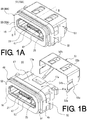
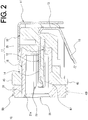
- the waterproof connector 10 of the first embodiment is made up of a plurality of contacts 12, a metal shell 16 with the contacts 12 disposed therein, a reinforcing member 25 disposed under the contacts 12, and a housing 32 formed to integrate these elements.
- the housing 32 is made of an insulating resin material by insert molding such that the contacts 12 supported/fixed at predetermined intervals, the shell 16, and the reinforcing member 25 are integrated.
- the housing 32 is provided with a contact supporting portion 47 extended to support the contacts 12 disposed in the shell 16 and the contact supporting portion 47 is interposed between the contact 12 located on the upper side and the reinforcing member 25 located on the lower side.
- a configuration of the contacts 12, the shell 16, and the reinforcing member 25 integrally formed with the housing 32 by insert molding is collectively referred to as an insert molded body 11.
- the shell 16 has a waterproof portion 49 on the side connected to a counterpart connector.
- the waterproof portion 49 is disposed with a waterproof member 50 formed integrally with the shell 16 by insert molding of an elastic material.
- a metal shield cover 51 is mounted on the housing 32, covering a portion of the housing 32.
- contacts 12 making up the waterproof connector 10 of the first embodiment are so-called compression type contacts pressed into contact with a substrate etc., in this description, surface-mount type contacts are also available.
- the contacts 12 of the first embodiment are made up of a plurality of, for example, five, contacts 12 and are arranged symmetrically relative to the center contact 12. Although respective shapes are different, the five contacts 12 of the first embodiment have a common configuration and, therefore, as depicted in Fig. 6B , one of the contacts 12 will representatively be described.
- the contact 12 has a contact main body 13 made of a conductive metal plate as depicted in Fig. 6B and is disposed with a connecting portion 14 connected to a counterpart contact included in a counterpart connector on one side and a contacting portion 15 brought into contact with a substrate etc., included in the device on the other side.
- the contact main body 13 is bent in the same direction at two positions near the center portion.
- the contact main body 13 is bent into a form corresponding to a position at which the contact 12 is located in the housing 32, i.e., is bent at two positions in opposite directions.
- a tip part 14a of the connecting portion 14 of the contact 12 is formed into a curved surface for smooth connection with the counterpart contact of the counterpart connector.
- a tip part 15a of the contacting portion 15 of the contact 12 is also formed into a curved shape for smooth contact with the substrate etc.
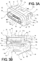
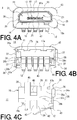
- the contact 12 in the insert molded body 11 is fixed to the housing 32 as depicted in Figs. 3A to 5B , and a portion of the contact main body 13 is integrally fixed to the housing 32 by insert molding while a surface of the connecting portion 14 other than the surface brought into contact with the counterpart contact is fixed to and integrated with the contact supporting portion 47 of the housing 32.
- the contacts 12 of the first embodiment are made up of five contacts, this is not a limitation and the number of contacts may be less than five or more than five.
- the shape of the contact 12 is not limited to those depicted in Figs. 6A and 6B and may be an arbitrary shape.
- the shell 16 will be described. As depicted in Figs. 3B , 4A , and 7A to 7E , the shell 16 is made up of an upper surface 17, a bottom surface 18, a first side surface 19, and a second side surface 20 made of metal plates having a predetermined thickness.
- the shell 16 is formed into a tubular flattened rectangular parallelepiped having an insertion port 21 into which the counterpart connector is inserted on one side and a projection port 22 from which the arranged contacts 12 are projected on the other side and having a space 23 in which a plurality of the contacts 12 is disposed.
- the upper surface 17 of the shall 16 is formed into a rectangular shape with a predetermined area and is provided with respective first extending portions 17a in a narrow plate shape extended from both ends of the upper surface 17 on the projection port 22 side.
- the first extending portions 17a are portions brought into contact with the shield cover 51 described later to conduct electricity (see Figs. 1A and 1B ).
- First projecting portions 17b in a narrow plate shape projected toward the first and second side surfaces 19 and 20 of the shell 16 are respectively formed from the first extending portions 17a.
- the first projecting portions 17b are used when the shell 16 is placed in an insert molding machine described later, and are partially integrally formed with the housing 32 to further strengthen the integration between the shell 16 and the housing 32.
- the bottom surface 18 of the shell 16 is formed into a rectangular shape with a predetermined area and has concave portions 18a formed at two positions by concaving portions of the bottom surface 18.
- the concave portions 18a are formed to be engaged with convex portions formed on the counterpart connector at the time of connection with the counterpart connector so as to certainly establish the connection between the waterproof connector 10 of the first embodiment and the counterpart connector, and can act as a retainer so that the connectors hardly come off.
- the formation of the concave portions 18a in the bottom surface 18 increases an area brought into contact with the housing 32, thereby further strengthening the integration with the housing 32.
- the shell 16 depicted in Fig. 7A portions linked to the upper surface 17 and the first and second side surfaces 19 and 20 are formed in a slanted manner.
- the shape of the shell 16 is formed in accordance with a shape of the counterpart connector to be connected.
- a taper 21 a is formed in the insertion port 21 of the shell 16 toward the inside space 23 such that the counterpart connector can smoothly be
- the housing 32 is not formed on an outer circumference of the shell 16 on the insertion port 21 side in the insert molded body 11 and the shell 16 is exposed. This exposure portion of the shell 16 forms an outer circumferential exposure portion 24 disposed with the waterproof member 50.
- the reinforcing member 25 is a plate-shaped body with a predetermined thickness and has a support surface 26 formed with an area capable of supporting a plurality of the contacts 12 arranged in the space 23 in the shell 16.
- the support surface 26 has a front portion 27 disposed on the insertion port 21 side of the shell 16, a rear portion 28 opposing the front portion 27, a first side portion 29, and a second side portion 30.
- the front portion 27 and the first and second side portions 29 and 30 of the supporting surface 26 are respectively provided with a front standing portion 27a, a first side standing portion 29a, and a second side standing portion 30a standing at a predetermined height.
- a plurality of holes 31 is formed on the front portion 27 side of the support surface 26 from the front standing portion 27a into the support surface 26.
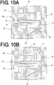
- the holes 31 are for the purpose of being combined with a metal mold 56 disposed in the insert molding machine so that the contacts 12 arranged within the shell 16 are supported by the metal mold (see Fig. 10A ).
- the holes 31 are also for the purpose of causing a resin material to enter through a gap between the metal mold and the holes 31 of the reinforcing member 25 when the housing 32 is formed, so as to form the contact supporting portion 47 and cause the integration between the housing 32 and the reinforcing member 25.
- a second extending portion 28a extended in the direction of the rear portion 28 is formed in the rear portion 28 of the support surface 26, and second projecting portions 28b in a narrow plate shape are respectively formed and projected from the second extending portion 28a toward the first and second side portions 29 and 30.
- the second projecting portions 28b are used when the reinforcing member 25 is placed in the insert molding machine described later, and are partially integrally formed with the housing 32 to further strengthen the integration between the reinforcing member 25 and the housing 32.
- the housing 32 will be described. As depicted in Fig. 3A to 5B , the housing 32 is formed to cover the outside of the shell 16 with the contact 12 and the reinforcing member 25 integrated therein.
- the housing 32 has a front surface portion 33 disposed on the insertion port 21 side of the shell 16, a back surface portion 34 opposing the front surface portion 33, a first side surface portion 35, and a second side surface portion 36 and is formed into a rectangular parallelepiped shape having an upper surface portion 41 and a bottom surface portion 42.
- the upper surface portion 41, the first side surface portion 35, the bottom surface portion 42, and the second side surface portion 36 have respective portions projected on the front surface portion 33 side of the housing 32 and these projecting portions form an annular flange portion 45.
- the front surface portion 33 of the housing 32 allows the shell 16 to project and has a surface formed larger than the insertion port 21 of the projecting shell 16.
- the recess portions 18a formed in the shell 16 are formed to partially overlap with the front surface portion 33.
- the outer circumference of the shell 16 projecting from the front surface portion 33 of the housing 32 forms the outer circumferential exposure portion 24 disposed with the waterproof member 50 acting as the waterproof portion 49.
- the outer circumferential exposure portion 24 is a range from the insertion port 21 to the front surface portion 33 formed in the housing 33.
- the back surface portion 34 of the housing 32 allows the contacts 12 to project and has an insertion portion 46a into which the contacts 12 are inserted.
- the back surface portion 34 has respective partition wall portions 43 between the contacts 12 so as to restrain the contacts 12 passing thorough the insert portion 46a from contacting with each other.
- the back surface portion 34 is provided with a locking projection 34a locking a portion of the shield cover 51 described later.
- the upper surface portion 41 of the housing 32 is provided with an opening portion 41a exposing portions of the upper surface 17 and the first extending portions 17a of the shell 16.
- the shell 16 exposed from the opening portion 41a comes into contact with a portion of the shield cover 51 described later. Therefore, the shape of the opening portion 41a is not limited thereto, may be disposed with a plurality of opening portions, and may have an arbitrary shape.
- the bottom surface portion 42 of the housing 32 is formed with a predetermined area and the partition wall portions 43 of the back surface portion 34 are formed across the bottom surface portion 42.
- the bottom surface portion 42 has end partition wall portions 44 formed shorter than the partition wall portions 43 in the axial direction of the housing 32 on the outside of the contacts 12 disposed on the outermost sides along with the partition wall portions 43 from the back surface portion 34.
- the partition wall portions 43 and the end partition wall portions 44 are formed higher than the bottom surface portion 42 in the height direction of the housing 32.
- the height is set to form gaps such that when the waterproof connector 10 is pressed and brought into contact with the substrate in the device, the contacting portions 15 of the contacts 12 pressed by a pressing force can be fit into the gaps.
- the end portions of the partition wall portions 43 and the end partition wall portions 44 on the bottom surface 42 side act as portions placed on the substrate etc., so that the waterproof connector can stably be mounted on the substrate.
- the first side surface portion 35 and the second side surface portion 36 of the housing 32 have a common configuration except that the portions are symmetrical and, therefore, the first side surface portion 35 will representatively be described.
- the first side surface portion 35 of the housing 32 are formed in two stages of a lower stage portion 35a and a higher stage portion 35b.
- the first projecting portions 17b of the shell 16 and the second projecting portions 28b of the reinforcing member 25 placed in the insert molding machine are projected from the lower stage portion 35a when integrated in the housing 32.
- the higher stage portion 35b has grooves 37 formed on the upper surface portion 41 side and the bottom surface portion 42 side, and the grooves 37 are linked at a center portion. This linked portion at the center portion acts as an engagement portion 38 engaged with the shield cover 51 described later.
- a protruding portion 39 and groove portions 40 are formed on the side surface side of the higher stage portion 35b.
- the protruding portion 39 and the groove portions 40 are used along with the flange portion 45 when attached to a housing making up the device. Therefore, the protruding portion 39, the groove portions 40, and the flange portion 45 are formed in accordance with an attaching portion etc., formed on the housing of the device.
- a closing portion 46 closing the projection port 22 of the shell 16 is formed on the side of the housing 32 opposite to the insertion port 21 in the shell 16.
- the contact supporting portion 47 is formed from the closing portion 46 into the shell 16.
- the contact supporting portion 47 is formed on the reinforcing member 25 and the contacts 12 are disposed on the upper side across the contact supporting portion 47. Separating portions 47a separating each of the contacts 12 are formed on the contact 12 side of the contact supporting portion 47 (see Figs. 3A and 4A ).
- the contact supporting portion 47 is provided with contact exposing portions 48 exposing the contacts 12 such that the upper sides of the contacts 12 can be connected to the counterpart contacts of the counterpart connector.
- a tip portion 47b of the contact supporting portion 47 is formed to cover the tip sides of the connecting portions 14 of the contacts 12.
- the tip sides of the tip portion 47b and the separating portions 47a of the contact supporting portion 47 have a taper formed to facilitate insertion of the counterpart contacts.
- the tip side of the contact supporting portion 47 and the tip sides of the separating portions 47a are formed on the front standing portion 27a of the reinforcing member 25 disposed on the underside.
- the separating portions 47a are also formed on the first side standing portion 29a and the second side standing portion 30a of the reinforcing member 25.
- the reinforcing member 25 reinforces the strength of the contact supporting portion 47 to restrain the contacts from bending or deforming even when the contacts are pressed at the time of connection with the counterpart connectors so that the contact pressure of the contacts can be retained.
- the waterproof member 50 of the first embodiment will be described with reference to Fig. 1 .
- the waterproof member 50 of the first embodiment is formed integrally with the outer circumferential exposure portion 24 disposed on the shell 16 by insert molding of an elastic material. Therefore, the waterproof member 50 of the first embodiment is formed by first forming an insert molded body and then placing this insert molded body in an insert molding machine to insert-mold the waterproof member 50.
- the waterproof member 50 is formed into an annular shape surrounding the outer circumferential exposure portion 24 of the shell 16 and is formed into substantially the same size as that of the front surface portion 33 of the housing 32. When attached to the housing of the device, the waterproof member 50 fits between the housing and the waterproof connector 10 and deforms to fill a gap so that the infiltration of water etc. can be prevented.
- the elastic material of the waterproof member 50 is preferably an elastically deformable material capable of closely adhering to the metal shell and particularly preferably silicon rubber.
- convexes and concaves are formed on an outer circumferential portion 50a of the waterproof member 50 depicted in Fig. 1B to increase adhesiveness, this is not a limitation and the outer circumferential portion 50a may not be provided with convexes and concaves given that adhesiveness is acquired, or may be formed into another shape.
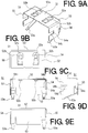
- the shield cover 51 will be described with reference to Figs. 1A, 1B and 9A to 9E .
- the shield cover 51 is formed by bending a metal plate.
- the shield cover 51 is formed into a size partially covering the housing 32 and is made up of an upper surface plate portion 52 covering the upper surface portion 41 of the housing 32, a back surface plate portion 53 covering the back surface portion 34 of the housing 32, and a first side surface plate portion 54 and a second side surface plate portion 55 covering the first side surface portion 35 and the second side surface portion 36, respectively, of the housing 32.
- the shield cover 51 is opened in portions corresponding to the front surface portion 33 and the bottom surface portion 42 of the housing 32 and is inserted and mounted on the housing 32 through these portions.
- the upper surface plate portion 52 of the shield cover 51 is formed into a size such that the upper surface portion 41 except the flange portion 45 of the housing 32 is covered.
- the upper surface plate portion 52 is provided with two open holes 52a and the open holes 52a are provided with conductive pieces 52b formed integrally with the upper surface plate portion 52.
- the conductive pieces 52b are brought into contact with the first extending portions 17a on the upper surface of the shell 16 through the opening portion 41a of the housing 32 of the insert molded body.
- the back surface plate portion 53 of the shield cover 51 has a center portion formed into a size covering the back surface portion 34 of the housing 32 and into substantially the same height as that of the partition wall portions 43 of the back surface portion 34 of the housing 32. This height is formed such that when the waterproof connector 10 is pressed by the substrate and the partition wall portions 43 are placed, a slight gap is made between the substrate and the back surface plate portion 53.
- a pair of cover terminals 53a brought into contact with the substrate is formed in the both end portions of the back surface plate portion 53.
- the cover terminals 53a are brought into contact with the substrate to be conductive so that static electricity charged in the shield cover 51 can be released.
- the shield cover 51 is brought into contact with the shell 16 through the conductive pieces 52b so that static electricity charged in the shell 16 can also be released.
- the same effect can be acquired for the reinforcing member 25 by bringing the reinforcing member 25 and the shield cover 51 into contact with each other.
- Portions of the cover terminals 53a coming into contact with the substrate are formed into curved surfaces to enable smooth contact.
- the first side surface plate portion 54 and the second side surface plate portion 55 of the shield cover 51 will be described.
- the first side surface plate portion 54 and the second side surface plate portion 55 are the same except that the shapes are symmetrical and, therefore, the first side surface plate portion 54 will representatively be described.
- the first side surface plate portion 54 is formed into a size covering the first side surface portion 35 except the flange portion 45 of the housing 32.
- the first side surface plate portion 54 is provided with an engagement groove 54a engaged with the engagement portion 38 formed in the higher stage portion 35b of the first side surface portion 35 of the housing 32.
- a convex portion 54b is formed in the engagement groove 54a and the convex portion 54b can fit into the engagement portion 38 to retain the shield cover 51.
- the first side surface plate portion 54 is provided with a locking piece 54c locked by the locking projection 34a formed on the back surface portion 34 of the housing 32 such that the locking piece 54c is bent toward the inside of the shield cover 51 (see Fig. 9C ) and the shield cover 51 can be restrained from rocking and can be positioned and fixed by locking the locking projection 34a and the locking piece 54c.
- Such a configuration enables the waterproof connector of the first embodiment to have a portion forming the waterproof member formed thinner and, therefore, the waterproof connector can be downsized.
- the insert molded body 11 making up the waterproof connector 10 of the first embodiment is formed.
- a plurality of the contacts 12, the shell 16, and the reinforcing member 25 separately formed in advance are placed in an insert molding machine (see Fig. 10A ).
- the metal mold 56 for forming the housing 32 is then placed and a resin material is injected into a hollow portion 32' of the insert molding machine to form the housing 32, thereby forming the insert molded body 11 with the contacts 12, the shell 16, and the reinforcing member 25 integrated.
- the contacts 12, the shell 16, and the reinforcing member 25 are formed by punching work, bending work, pressing work, etc., of metal plates.
- the waterproof portion 49 is then formed.
- the waterproof portion 49 is formed integrally with the outer circumferential exposure portion 24 of the shell 16 of the insert molded body 11 by insert molding of the waterproof member 50.
- the preliminarily formed insert molded body 11 is disposed in an insert molding machine in which a metal mold 57 for molding the waterproof member 50 is placed (see Fig. 10B ).
- An elastic material is then injected into a hollow portion 50' of the insert molding machine to form the waterproof member 50 integrally with the outer circumferential exposure portion 24 of the shell 16 of the insert molded body 11.
- the elastic material forming the waterproof member is preferably a material easily adhering to the metal shell and particularly preferably silicon rubber.
- the preliminarily formed shield cover 51 is attached to the housing 32 of the insert molded body 11 with the waterproof member 50 formed.
- the shield cover 51 is fitted from the back surface portion 34 side of the housing 32 of the insert molded body 11 to engage the engagement portions 38 formed in the first and second side surface portions 35 and 36 of the housing 32 with the engagement groove 54a formed in the shield cover 51.
- the locking projection 34a on the back surface portion 34 of the housing 32 is locked with the locking piece 54c of the shield cover 51.
- the waterproof connector 10 of the first embodiment is completed (see Fig. 1A ).
- the waterproof member is formed by insert molding as described above and, therefore, the small-sized waterproof connector can easily be manufactured.
- the waterproof connector 10 of the first embodiment has been described as the configuration having the waterproof member 50 formed by insert molding as the waterproof portion 49.
- a waterproof connector 10A of a second embodiment will be described as a configuration having a separately formed waterproof component 50A attached as a waterproof portion 49A. Since the waterproof connector 10A of the second embodiment is only different in configuration of the waterproof portion 49A from the waterproof connector 10 of the first embodiment, the other common constituent elements are denoted by the same reference numerals and will not be described.
- the waterproof connector 10A of the second embodiment is made up of the insert molded body 11 made up of a plurality of the contacts 12, the shell 16, the reinforcing member 25, and the housing 32, the waterproof component 50A attached to the insert molded body 11, and the shield cover 51.
- the configuration of the insert molded body 11 and the shield cover 51 is common with that of the first embodiment and therefore will not be described.
- the waterproof component 50A of the second embodiment is an annular body made of an elastic material having an attachment port 50Aa to which the outer circumferential exposure portion 24 of the shell 16 is inserted and attached in the center.
- the width of the waterproof component 50A is formed as a width covering the outer circumferential exposure portion 24 when attached to the outer circumferential exposure portion 24 of the shell 16.
- the thickness of the waterproof component 50A is formed as substantially the same thickness as that of the front surface portion 33 of the housing 32 of the insert molded body 11.
- the attachment port 50Aa is formed into substantially the same shape as the outer shape of the outer circumferential exposure portion 24 so that the waterproof component 50A can be attached to the outer circumferential exposure portion 24 of the shell 16.
- the attachment port 50Aa has concaves 50Ab formed to be fit to the concave portions 18a formed in the bottom surface 18 of the shell 16.
- the inner circumference of the attachment port 50Aa is formed slightly smaller than the outer circumferential exposure portion 24 and can be attached in a closely adhering manner by fitting to the outer circumferential exposure portion 24.
- This attachment can be implemented not only by fitting but also by using an adhesive as needed.
- the small-sized waterproof connector can easily be manufactured by attaching the waterproof component separately formed from an elastic material.
- a manufacturing method of the waterproof connector 10A of the second embodiment will be described. First, the insert molded body 11 making up the waterproof connector 10A of the second embodiment is formed. The formation of the insert molded body 11 is the same as the first embodiment and therefore will not be described in detail.
- the separately formed waterproof component 50A is attached to the outer circumferential exposure portion 24 of the shell 16 of the insert molded body 11. This attachment is achieved by fitting the attachment port 50Aa of the waterproof component 50A to the outer circumferential exposure portion 24. Since the attachment port 50Aa of the waterproof component 50A is formed slightly smaller than the outer circumferential exposure portion 24, the waterproof component 50A can be attached in a closely adhering manner to the outer circumferential exposure portion 24.
- the shield cover 51 is then attached to the housing 32 of the insert molded body 11.
- the attachment of the shield cover 51 is the same as the first embodiment and therefore will not be described in detail.
- the manufacturing of waterproof connector of the second embodiment is completed.
- the small-sized waterproof connector can easily be manufactured by attaching the waterproof component separately formed from an elastic material.
Claims (9)
- Connecteur étanche (10, 10A) comprenant :au moins un contact (12) constitué d'un matériau conducteur ;une enveloppe (16) constituée de métal à l'intérieur de laquelle le contact est disposé et ayant un orifice d'insertion (21) dans lequel un connecteur complémentaire peut être inséré sur un côté ; etun boîtier (32, 33) constitué d'un matériau en résine isolant formé de manière à recouvrir l'extérieur de l'enveloppe (16) et à fixer le contact (12) et l'enveloppe (16) comme une structure intégrale ;
dans lequell'enveloppe (16) se projette depuis le boîtier (33) du côté de l'orifice d'insertion (21) vers le connecteur complémentaire et est exposée pour former une partie d'exposition circonférentielle extérieure (24),la partie d'exposition circonférentielle extérieure (24) de l'enveloppe (16) est disposée avec une partie étanche (49, 49A),caractérisé en ce que
la partie étanche (49, 49A) est formée d'une seule pièce à partir d'un matériau élastique par moulage par insertion en une forme annulaire, de telle sorte qu'une extrémité de la partie étanche (49, 49A) est alignée avec une extrémité de l'orifice d'insertion (21), et de telle sorte que la partie étanche (49, 49A) entoure uniquement la partie d'exposition circonférentielle extérieure (24) de l'enveloppe (16). - Connecteur étanche de la revendication 1, dans lequel
la partie étanche est constituée de caoutchouc de silicone. - Connecteur étanche de la revendication 1 ou 2, dans lequel
la partie étanche est un élément étanche (50) formé d'une seule pièce à partir du matériau élastique avec l'enveloppe par moulage par insertion. - Connecteur étanche de la revendication 2 ou la revendication 3, dans lequel l'enveloppe est fermée sur le côté opposé à l'orifice d'insertion par une partie de fermeture (46) formée dans le boîtier,
la partie de fermeture fixe le contact de telle sorte qu'un côté (14) du contact est disposé à l'intérieur de l'enveloppe et l'autre côté (15) du contact est projeté à l'extérieur de l'enveloppe,
une partie de la partie de fermeture où le contact est fixé est pourvue d'une partie de support de contact (47) prolongée depuis celle-ci pour supporter le contact,
la partie de support de contact est formée avec une partie d'exposition de contact (48) pour exposer une partie du contact avec laquelle un contact complémentaire du connecteur complémentaire vient en contact, et
un élément de renforcement en forme de plaque (25) est intégralement disposé sur le côté opposé à la partie d'exposition de contact de l'autre côté de la partie de support de contact. - Connecteur étanche de l'une quelconque des revendications 2 à 4, dans lequel
un couvercle de protection métallique (51) recouvrant le boîtier est monté sur le boîtier,
au moins une partie d'ouverture (42) pour exposer une partie d'une surface extérieure de l'enveloppe est formée dans le boîtier dans une partie recouverte par le couvercle de protection, et
le couvercle de protection et l'enveloppe entrent en contact l'un avec l'autre à travers la partie d'ouverture. - Procédé de fabrication du connecteur étanche (10, 10A) de la revendication 1, le procédé comprenant au moins les étapes suivantes :1) placer dans une machine de moulage par insertion (56, 57) au moins un contact (12) constitué d'un matériau conducteur et une enveloppe (16) constituée de métal à l'intérieur de laquelle le contact est disposé et un orifice d'insertion (21) dans lequel un connecteur complémentaire peut être inséré sur un côté, et former un boîtier à partir d'un matériau en résine isolant par moulage par insertion d'une seule pièce avec le contact et l'enveloppe de telle sorte que le boîtier recouvre l'extérieur de l'enveloppe de manière à exposer l'enveloppe au niveau de la circonférence extérieure et à proximité de l'orifice d'insertion pour former une partie d'exposition circonférentielle extérieure (24) ; et2) disposer une partie étanche (49, 49A) qui est formée d'une seule pièce à partir d'un matériau élastique par moulage par insertion en une forme annulaire sur la partie d'exposition circonférentielle extérieure de l'enveloppe de manière à ce qu'elle entre en contact avec une partie du côté de l'orifice d'insertion et de telle sorte qu'une extrémité de la partie étanche soit alignée avec une extrémité de l'orifice d'insertion, et la partie étanche entoure uniquement la partie d'exposition circonférentielle extérieure de l'enveloppe.
- Procédé de fabrication d'un connecteur étanche de la revendication 6, dans lequel
à l'étape 2), la partie étanche est constituée de caoutchouc de silicone. - Procédé de fabrication d'un connecteur étanche de la revendication 6 ou la revendication 7, dans lequel
à l'étape 1), une partie de fermeture (46) est formée dans le boîtier pour fermer l'enveloppe sur le côté opposé à l'orifice d'insertion, dans lequel
la partie de fermeture fixe le contact de telle sorte qu'un côté (14) du contact est disposé à l'intérieur de l'enveloppe et l'autre côté (15) du contact est projeté à l'extérieur de l'enveloppe et une partie de la partie de fermeture où le contact est fixé est pourvue d'une partie de support de contact (47) prolongée depuis celle-ci pour supporter le contact,
la partie de support de contact est formée avec une partie d'exposition de contact (48) pour exposer une partie du contact avec laquelle un contact complémentaire du connecteur complémentaire vient en contact, et
un élément de renforcement en forme de plaque (25) est intégralement disposé sur le côté opposé à la partie d'exposition de contact de l'autre côté de la partie de support de contact. - Procédé de fabrication d'un connecteur étanche de l'une quelconque des revendications 6 à 8, comprenant en outre une étape consistant à3) monter un couvercle de protection (51) pour recouvrir le boîtier, dans lequel
à l'étape 1), au moins une partie d'ouverture (42) exposant une partie de l'enveloppe est formée dans le boîtier dans une partie recouverte par le couvercle de protection, et
à l'étape 3), le couvercle de protection et l'enveloppe entrent en contact l'un avec l'autre à travers la partie d'ouverture.
Applications Claiming Priority (1)
| Application Number | Priority Date | Filing Date | Title |
|---|---|---|---|
| JP2013084064A JP5913183B2 (ja) | 2013-04-12 | 2013-04-12 | 防水コネクタ及びその製造方法 |
Publications (2)
| Publication Number | Publication Date |
|---|---|
| EP2790274A1 EP2790274A1 (fr) | 2014-10-15 |
| EP2790274B1 true EP2790274B1 (fr) | 2017-03-15 |
Family
ID=50473059
Family Applications (1)
| Application Number | Title | Priority Date | Filing Date |
|---|---|---|---|
| EP14163215.8A Active EP2790274B1 (fr) | 2013-04-12 | 2014-04-02 | Connecteur étanche et son procédé de fabrication |
Country Status (4)
| Country | Link |
|---|---|
| US (1) | US9437956B2 (fr) |
| EP (1) | EP2790274B1 (fr) |
| JP (1) | JP5913183B2 (fr) |
| CN (2) | CN104103949A (fr) |
Families Citing this family (18)
| Publication number | Priority date | Publication date | Assignee | Title |
|---|---|---|---|---|
| JP6257182B2 (ja) * | 2013-06-20 | 2018-01-10 | 株式会社エクセル電子 | 防水コネクタ及び電子機器、防水コネクタの製造方法 |
| US10826255B2 (en) * | 2013-07-19 | 2020-11-03 | Foxconn Interconnect Technology Limited | Flippable electrical connector |
| JP6368504B2 (ja) | 2014-03-07 | 2018-08-01 | 宏致電子股▲ふん▼有限公司Aces Electronics Co.,Ltd. | 電気コネクタ |
| CN204045829U (zh) * | 2014-07-16 | 2014-12-24 | 富士康(昆山)电脑接插件有限公司 | 电连接器 |
| JP5905977B1 (ja) | 2015-01-29 | 2016-04-20 | 日本航空電子工業株式会社 | コネクタの製造方法およびコネクタ |
| EP3269012B1 (fr) * | 2015-03-13 | 2021-12-08 | Fci Usa Llc | Connecteur électrique et procédé d'assemblage |
| CN105375182B (zh) * | 2015-03-31 | 2018-08-07 | 富士康(昆山)电脑接插件有限公司 | 电连接器及其制造方法 |
| CN105356109A (zh) * | 2015-11-27 | 2016-02-24 | 富士康(昆山)电脑接插件有限公司 | 电连接器 |
| CN105655839A (zh) * | 2016-01-26 | 2016-06-08 | 沈阳兴华航空电器有限责任公司 | 一种接触体镶嵌塑压密封方法 |
| CN106374249B (zh) * | 2016-04-01 | 2019-06-28 | 富士康(昆山)电脑接插件有限公司 | 电连接器及其制造方法 |
| JP6737011B2 (ja) * | 2016-07-01 | 2020-08-05 | 株式会社オートネットワーク技術研究所 | シールドコネクタ |
| CN205944583U (zh) * | 2016-07-12 | 2017-02-08 | 富士康(昆山)电脑接插件有限公司 | 电连接器 |
| JP6340041B2 (ja) * | 2016-07-26 | 2018-06-06 | Smk株式会社 | 電気コネクタ |
| CN108270138B (zh) * | 2016-12-30 | 2019-07-26 | 富士康(昆山)电脑接插件有限公司 | 电连接器制造方法 |
| KR102543956B1 (ko) * | 2017-03-23 | 2023-06-19 | 엘에스엠트론 주식회사 | 리셉터클 커넥터 |
| JP7167761B2 (ja) * | 2019-02-15 | 2022-11-09 | 住友電装株式会社 | 回路基板用コネクタ |
| CN111106487A (zh) * | 2020-01-07 | 2020-05-05 | 东莞立德精密工业有限公司 | 一种连接器 |
| CN211265834U (zh) * | 2020-03-04 | 2020-08-14 | 东莞崧腾电子有限公司 | 高压连接器 |
Citations (2)
| Publication number | Priority date | Publication date | Assignee | Title |
|---|---|---|---|---|
| CN102368579A (zh) * | 2010-06-25 | 2012-03-07 | 日本压着端子制造株式会社 | 连接器用密封壳和电连接器 |
| CN102544888A (zh) * | 2010-12-02 | 2012-07-04 | 日本压着端子制造株式会社 | 防水连接器及其制造方法 |
Family Cites Families (19)
| Publication number | Priority date | Publication date | Assignee | Title |
|---|---|---|---|---|
| JP2598584Y2 (ja) * | 1991-09-12 | 1999-08-16 | 矢崎総業株式会社 | 組立式シールドコネクタ |
| JP3265795B2 (ja) * | 1994-01-31 | 2002-03-18 | ミツミ電機株式会社 | 電気コネクタ |
| JP2902292B2 (ja) * | 1994-02-10 | 1999-06-07 | 株式会社東海理化電機製作所 | コネクタ用ハウジング及びその製造方法 |
| JPH10294024A (ja) * | 1997-04-18 | 1998-11-04 | Enomoto:Kk | 電気電子部品及びその製造方法 |
| US6739919B2 (en) * | 2001-12-27 | 2004-05-25 | The Furukawa Electric Co., Ltd. | Wiring base and electrical connection box |
| JP4849109B2 (ja) * | 2008-09-10 | 2012-01-11 | パナソニック電工株式会社 | レセプタクルコネクタ及びその製造方法 |
| JP5390998B2 (ja) | 2009-09-01 | 2014-01-15 | 矢崎総業株式会社 | コネクタ |
| WO2011108679A1 (fr) | 2010-03-03 | 2011-09-09 | 株式会社 エクセル電子 | Connecteur et dispositif de connexion pour un équipement électronique |
| US8246383B2 (en) | 2010-03-19 | 2012-08-21 | Apple Inc. | Sealed connectors for portable electronic devices |
| CN201789147U (zh) | 2010-05-21 | 2011-04-06 | 富港电子(东莞)有限公司 | 电连接器 |
| CN201725958U (zh) | 2010-06-04 | 2011-01-26 | 富港电子(东莞)有限公司 | 防水电连接器 |
| JP5625594B2 (ja) * | 2010-08-02 | 2014-11-19 | Nok株式会社 | コネクターシール及びその製造方法 |
| JP5593162B2 (ja) * | 2010-08-18 | 2014-09-17 | 矢崎総業株式会社 | 防水栓 |
| JP5623836B2 (ja) * | 2010-09-09 | 2014-11-12 | 日本圧着端子製造株式会社 | 防水コネクタの製造方法 |
| US7922535B1 (en) * | 2010-11-05 | 2011-04-12 | Cheng Uei Precision Industry Co., Ltd. | Electrical connector |
| US8052467B1 (en) | 2010-12-22 | 2011-11-08 | Cheng Uei Precision Industry Co., Ltd. | Electrical connector |
| CN202217852U (zh) | 2011-09-02 | 2012-05-09 | 富港电子(东莞)有限公司 | 插座连接器 |
| CN202585914U (zh) | 2012-03-26 | 2012-12-05 | 富士康(昆山)电脑接插件有限公司 | 电连接器 |
| CN103647173B (zh) * | 2013-11-25 | 2017-12-01 | 连展科技电子(昆山)有限公司 | 插座电连接器之补强结构 |
-
2013
- 2013-04-12 JP JP2013084064A patent/JP5913183B2/ja active Active
-
2014
- 2014-03-25 US US14/224,366 patent/US9437956B2/en active Active
- 2014-04-02 EP EP14163215.8A patent/EP2790274B1/fr active Active
- 2014-04-11 CN CN201410144114.3A patent/CN104103949A/zh active Pending
- 2014-04-11 CN CN201711478695.4A patent/CN108281839B/zh active Active
Patent Citations (2)
| Publication number | Priority date | Publication date | Assignee | Title |
|---|---|---|---|---|
| CN102368579A (zh) * | 2010-06-25 | 2012-03-07 | 日本压着端子制造株式会社 | 连接器用密封壳和电连接器 |
| CN102544888A (zh) * | 2010-12-02 | 2012-07-04 | 日本压着端子制造株式会社 | 防水连接器及其制造方法 |
Also Published As
| Publication number | Publication date |
|---|---|
| EP2790274A1 (fr) | 2014-10-15 |
| CN108281839B (zh) | 2020-06-30 |
| JP2014207140A (ja) | 2014-10-30 |
| CN104103949A (zh) | 2014-10-15 |
| JP5913183B2 (ja) | 2016-04-27 |
| CN108281839A (zh) | 2018-07-13 |
| US9437956B2 (en) | 2016-09-06 |
| US20140308833A1 (en) | 2014-10-16 |
Similar Documents
| Publication | Publication Date | Title |
|---|---|---|
| EP2790274B1 (fr) | Connecteur étanche et son procédé de fabrication | |
| TWI506879B (zh) | 電連接器 | |
| US9692167B2 (en) | Connector mountable on a circuit board and having a coupling portion coupling an enclosing portion with a housing | |
| US7390197B2 (en) | Electronic device with integral connectors | |
| JP5051640B2 (ja) | 電子機器 | |
| US9793644B2 (en) | Waterproof connector and electronic equipment | |
| KR20160145190A (ko) | 전자기기의 방수 접속기구 및 전자기기 | |
| US20080220663A1 (en) | Shielded connector for reducing the deflection of the terminal | |
| JP2013054844A (ja) | 電気コネクタ | |
| US20080166921A1 (en) | Shielded connector | |
| JP3139061U (ja) | Usbコネクタ金属ハウジング構造 | |
| JP5240853B2 (ja) | 防水端子構造、及び電子機器 | |
| JP6050164B2 (ja) | 携帯機器 | |
| US7559799B2 (en) | Electrical connector | |
| JP2020047369A (ja) | コネクタ | |
| JP5861205B2 (ja) | 電気コネクタの製造方法 | |
| CN108988613B (zh) | 电源转换器及其电连接器模块 | |
| CN201294293Y (zh) | Usb连接器 | |
| KR20180051943A (ko) | 전자 제어 장치 | |
| TWI387160B (zh) | Electrical connector combination | |
| CN214013234U (zh) | 电子设备及汽车 | |
| US20230104592A1 (en) | Electrical connector | |
| TWI431860B (zh) | 連接器防水結構及使用其的可攜帶型電子裝置 | |
| JP6057372B2 (ja) | コネクタ | |
| JP2000251988A (ja) | 回路ユニット |
Legal Events
| Date | Code | Title | Description |
|---|---|---|---|
| PUAI | Public reference made under article 153(3) epc to a published international application that has entered the european phase |
Free format text: ORIGINAL CODE: 0009012 |
|
| 17P | Request for examination filed |
Effective date: 20140402 |
|
| AK | Designated contracting states |
Kind code of ref document: A1 Designated state(s): AL AT BE BG CH CY CZ DE DK EE ES FI FR GB GR HR HU IE IS IT LI LT LU LV MC MK MT NL NO PL PT RO RS SE SI SK SM TR |
|
| AX | Request for extension of the european patent |
Extension state: BA ME |
|
| RAP1 | Party data changed (applicant data changed or rights of an application transferred) |
Owner name: J.S.T MFG CO., LTD |
|
| RIN1 | Information on inventor provided before grant (corrected) |
Inventor name: NASU, TAKAHITO Inventor name: NAKAZAWA, YOICHI Inventor name: FUKAMI, TSUYOSHI |
|
| RAP1 | Party data changed (applicant data changed or rights of an application transferred) |
Owner name: J.S.T. MFG. CO., LTD. |
|
| R17P | Request for examination filed (corrected) |
Effective date: 20150415 |
|
| RBV | Designated contracting states (corrected) |
Designated state(s): AL AT BE BG CH CY CZ DE DK EE ES FI FR GB GR HR HU IE IS IT LI LT LU LV MC MK MT NL NO PL PT RO RS SE SI SK SM TR |
|
| 17Q | First examination report despatched |
Effective date: 20160209 |
|
| GRAP | Despatch of communication of intention to grant a patent |
Free format text: ORIGINAL CODE: EPIDOSNIGR1 |
|
| RIC1 | Information provided on ipc code assigned before grant |
Ipc: H01R 13/6581 20110101ALN20160912BHEP Ipc: H01R 12/72 20110101ALN20160912BHEP Ipc: H01R 43/00 20060101ALI20160912BHEP Ipc: H01R 13/52 20060101AFI20160912BHEP Ipc: H01R 43/24 20060101ALN20160912BHEP |
|
| INTG | Intention to grant announced |
Effective date: 20160929 |
|
| STAA | Information on the status of an ep patent application or granted ep patent |
Free format text: STATUS: GRANT OF PATENT IS INTENDED |
|
| GRAS | Grant fee paid |
Free format text: ORIGINAL CODE: EPIDOSNIGR3 |
|
| GRAA | (expected) grant |
Free format text: ORIGINAL CODE: 0009210 |
|
| STAA | Information on the status of an ep patent application or granted ep patent |
Free format text: STATUS: THE PATENT HAS BEEN GRANTED |
|
| AK | Designated contracting states |
Kind code of ref document: B1 Designated state(s): AL AT BE BG CH CY CZ DE DK EE ES FI FR GB GR HR HU IE IS IT LI LT LU LV MC MK MT NL NO PL PT RO RS SE SI SK SM TR |
|
| REG | Reference to a national code |
Ref country code: CH Ref legal event code: EP Ref country code: GB Ref legal event code: FG4D |
|
| REG | Reference to a national code |
Ref country code: IE Ref legal event code: FG4D |
|
| REG | Reference to a national code |
Ref country code: FR Ref legal event code: PLFP Year of fee payment: 4 |
|
| REG | Reference to a national code |
Ref country code: AT Ref legal event code: REF Ref document number: 876429 Country of ref document: AT Kind code of ref document: T Effective date: 20170415 |
|
| REG | Reference to a national code |
Ref country code: DE Ref legal event code: R096 Ref document number: 602014007498 Country of ref document: DE |
|
| REG | Reference to a national code |
Ref country code: NL Ref legal event code: MP Effective date: 20170315 |
|
| REG | Reference to a national code |
Ref country code: LT Ref legal event code: MG4D |
|
| PG25 | Lapsed in a contracting state [announced via postgrant information from national office to epo] |
Ref country code: NO Free format text: LAPSE BECAUSE OF FAILURE TO SUBMIT A TRANSLATION OF THE DESCRIPTION OR TO PAY THE FEE WITHIN THE PRESCRIBED TIME-LIMIT Effective date: 20170615 Ref country code: FI Free format text: LAPSE BECAUSE OF FAILURE TO SUBMIT A TRANSLATION OF THE DESCRIPTION OR TO PAY THE FEE WITHIN THE PRESCRIBED TIME-LIMIT Effective date: 20170315 Ref country code: LT Free format text: LAPSE BECAUSE OF FAILURE TO SUBMIT A TRANSLATION OF THE DESCRIPTION OR TO PAY THE FEE WITHIN THE PRESCRIBED TIME-LIMIT Effective date: 20170315 Ref country code: GR Free format text: LAPSE BECAUSE OF FAILURE TO SUBMIT A TRANSLATION OF THE DESCRIPTION OR TO PAY THE FEE WITHIN THE PRESCRIBED TIME-LIMIT Effective date: 20170616 Ref country code: HR Free format text: LAPSE BECAUSE OF FAILURE TO SUBMIT A TRANSLATION OF THE DESCRIPTION OR TO PAY THE FEE WITHIN THE PRESCRIBED TIME-LIMIT Effective date: 20170315 |
|
| REG | Reference to a national code |
Ref country code: AT Ref legal event code: MK05 Ref document number: 876429 Country of ref document: AT Kind code of ref document: T Effective date: 20170315 |
|
| PG25 | Lapsed in a contracting state [announced via postgrant information from national office to epo] |
Ref country code: BG Free format text: LAPSE BECAUSE OF FAILURE TO SUBMIT A TRANSLATION OF THE DESCRIPTION OR TO PAY THE FEE WITHIN THE PRESCRIBED TIME-LIMIT Effective date: 20170615 Ref country code: SE Free format text: LAPSE BECAUSE OF FAILURE TO SUBMIT A TRANSLATION OF THE DESCRIPTION OR TO PAY THE FEE WITHIN THE PRESCRIBED TIME-LIMIT Effective date: 20170315 Ref country code: RS Free format text: LAPSE BECAUSE OF FAILURE TO SUBMIT A TRANSLATION OF THE DESCRIPTION OR TO PAY THE FEE WITHIN THE PRESCRIBED TIME-LIMIT Effective date: 20170315 Ref country code: LV Free format text: LAPSE BECAUSE OF FAILURE TO SUBMIT A TRANSLATION OF THE DESCRIPTION OR TO PAY THE FEE WITHIN THE PRESCRIBED TIME-LIMIT Effective date: 20170315 |
|
| PG25 | Lapsed in a contracting state [announced via postgrant information from national office to epo] |
Ref country code: NL Free format text: LAPSE BECAUSE OF FAILURE TO SUBMIT A TRANSLATION OF THE DESCRIPTION OR TO PAY THE FEE WITHIN THE PRESCRIBED TIME-LIMIT Effective date: 20170315 |
|
| PG25 | Lapsed in a contracting state [announced via postgrant information from national office to epo] |
Ref country code: IT Free format text: LAPSE BECAUSE OF FAILURE TO SUBMIT A TRANSLATION OF THE DESCRIPTION OR TO PAY THE FEE WITHIN THE PRESCRIBED TIME-LIMIT Effective date: 20170315 Ref country code: CZ Free format text: LAPSE BECAUSE OF FAILURE TO SUBMIT A TRANSLATION OF THE DESCRIPTION OR TO PAY THE FEE WITHIN THE PRESCRIBED TIME-LIMIT Effective date: 20170315 Ref country code: SK Free format text: LAPSE BECAUSE OF FAILURE TO SUBMIT A TRANSLATION OF THE DESCRIPTION OR TO PAY THE FEE WITHIN THE PRESCRIBED TIME-LIMIT Effective date: 20170315 Ref country code: AT Free format text: LAPSE BECAUSE OF FAILURE TO SUBMIT A TRANSLATION OF THE DESCRIPTION OR TO PAY THE FEE WITHIN THE PRESCRIBED TIME-LIMIT Effective date: 20170315 Ref country code: RO Free format text: LAPSE BECAUSE OF FAILURE TO SUBMIT A TRANSLATION OF THE DESCRIPTION OR TO PAY THE FEE WITHIN THE PRESCRIBED TIME-LIMIT Effective date: 20170315 Ref country code: ES Free format text: LAPSE BECAUSE OF FAILURE TO SUBMIT A TRANSLATION OF THE DESCRIPTION OR TO PAY THE FEE WITHIN THE PRESCRIBED TIME-LIMIT Effective date: 20170315 Ref country code: EE Free format text: LAPSE BECAUSE OF FAILURE TO SUBMIT A TRANSLATION OF THE DESCRIPTION OR TO PAY THE FEE WITHIN THE PRESCRIBED TIME-LIMIT Effective date: 20170315 |
|
| PG25 | Lapsed in a contracting state [announced via postgrant information from national office to epo] |
Ref country code: PT Free format text: LAPSE BECAUSE OF FAILURE TO SUBMIT A TRANSLATION OF THE DESCRIPTION OR TO PAY THE FEE WITHIN THE PRESCRIBED TIME-LIMIT Effective date: 20170717 Ref country code: PL Free format text: LAPSE BECAUSE OF FAILURE TO SUBMIT A TRANSLATION OF THE DESCRIPTION OR TO PAY THE FEE WITHIN THE PRESCRIBED TIME-LIMIT Effective date: 20170315 Ref country code: SM Free format text: LAPSE BECAUSE OF FAILURE TO SUBMIT A TRANSLATION OF THE DESCRIPTION OR TO PAY THE FEE WITHIN THE PRESCRIBED TIME-LIMIT Effective date: 20170315 Ref country code: IS Free format text: LAPSE BECAUSE OF FAILURE TO SUBMIT A TRANSLATION OF THE DESCRIPTION OR TO PAY THE FEE WITHIN THE PRESCRIBED TIME-LIMIT Effective date: 20170715 |
|
| REG | Reference to a national code |
Ref country code: CH Ref legal event code: PL |
|
| REG | Reference to a national code |
Ref country code: DE Ref legal event code: R097 Ref document number: 602014007498 Country of ref document: DE |
|
| PLBE | No opposition filed within time limit |
Free format text: ORIGINAL CODE: 0009261 |
|
| STAA | Information on the status of an ep patent application or granted ep patent |
Free format text: STATUS: NO OPPOSITION FILED WITHIN TIME LIMIT |
|
| REG | Reference to a national code |
Ref country code: IE Ref legal event code: MM4A |
|
| PG25 | Lapsed in a contracting state [announced via postgrant information from national office to epo] |
Ref country code: MC Free format text: LAPSE BECAUSE OF FAILURE TO SUBMIT A TRANSLATION OF THE DESCRIPTION OR TO PAY THE FEE WITHIN THE PRESCRIBED TIME-LIMIT Effective date: 20170315 Ref country code: DK Free format text: LAPSE BECAUSE OF FAILURE TO SUBMIT A TRANSLATION OF THE DESCRIPTION OR TO PAY THE FEE WITHIN THE PRESCRIBED TIME-LIMIT Effective date: 20170315 |
|
| 26N | No opposition filed |
Effective date: 20171218 |
|
| PG25 | Lapsed in a contracting state [announced via postgrant information from national office to epo] |
Ref country code: LI Free format text: LAPSE BECAUSE OF NON-PAYMENT OF DUE FEES Effective date: 20170430 Ref country code: CH Free format text: LAPSE BECAUSE OF NON-PAYMENT OF DUE FEES Effective date: 20170430 Ref country code: LU Free format text: LAPSE BECAUSE OF NON-PAYMENT OF DUE FEES Effective date: 20170402 Ref country code: SI Free format text: LAPSE BECAUSE OF FAILURE TO SUBMIT A TRANSLATION OF THE DESCRIPTION OR TO PAY THE FEE WITHIN THE PRESCRIBED TIME-LIMIT Effective date: 20170315 |
|
| REG | Reference to a national code |
Ref country code: BE Ref legal event code: MM Effective date: 20170430 |
|
| REG | Reference to a national code |
Ref country code: FR Ref legal event code: PLFP Year of fee payment: 5 |
|
| PG25 | Lapsed in a contracting state [announced via postgrant information from national office to epo] |
Ref country code: IE Free format text: LAPSE BECAUSE OF NON-PAYMENT OF DUE FEES Effective date: 20170402 |
|
| PG25 | Lapsed in a contracting state [announced via postgrant information from national office to epo] |
Ref country code: BE Free format text: LAPSE BECAUSE OF NON-PAYMENT OF DUE FEES Effective date: 20170430 |
|
| PG25 | Lapsed in a contracting state [announced via postgrant information from national office to epo] |
Ref country code: MT Free format text: LAPSE BECAUSE OF NON-PAYMENT OF DUE FEES Effective date: 20170402 |
|
| PG25 | Lapsed in a contracting state [announced via postgrant information from national office to epo] |
Ref country code: HU Free format text: LAPSE BECAUSE OF FAILURE TO SUBMIT A TRANSLATION OF THE DESCRIPTION OR TO PAY THE FEE WITHIN THE PRESCRIBED TIME-LIMIT; INVALID AB INITIO Effective date: 20140402 |
|
| PG25 | Lapsed in a contracting state [announced via postgrant information from national office to epo] |
Ref country code: CY Free format text: LAPSE BECAUSE OF FAILURE TO SUBMIT A TRANSLATION OF THE DESCRIPTION OR TO PAY THE FEE WITHIN THE PRESCRIBED TIME-LIMIT Effective date: 20170315 |
|
| PG25 | Lapsed in a contracting state [announced via postgrant information from national office to epo] |
Ref country code: MK Free format text: LAPSE BECAUSE OF FAILURE TO SUBMIT A TRANSLATION OF THE DESCRIPTION OR TO PAY THE FEE WITHIN THE PRESCRIBED TIME-LIMIT Effective date: 20170315 |
|
| PG25 | Lapsed in a contracting state [announced via postgrant information from national office to epo] |
Ref country code: TR Free format text: LAPSE BECAUSE OF FAILURE TO SUBMIT A TRANSLATION OF THE DESCRIPTION OR TO PAY THE FEE WITHIN THE PRESCRIBED TIME-LIMIT Effective date: 20170315 |
|
| PG25 | Lapsed in a contracting state [announced via postgrant information from national office to epo] |
Ref country code: AL Free format text: LAPSE BECAUSE OF FAILURE TO SUBMIT A TRANSLATION OF THE DESCRIPTION OR TO PAY THE FEE WITHIN THE PRESCRIBED TIME-LIMIT Effective date: 20170315 |
|
| REG | Reference to a national code |
Ref country code: DE Ref legal event code: R082 Ref document number: 602014007498 Country of ref document: DE Representative=s name: D YOUNG & CO LLP, DE |
|
| PGFP | Annual fee paid to national office [announced via postgrant information from national office to epo] |
Ref country code: FR Payment date: 20230424 Year of fee payment: 10 Ref country code: DE Payment date: 20230420 Year of fee payment: 10 |
|
| PGFP | Annual fee paid to national office [announced via postgrant information from national office to epo] |
Ref country code: GB Payment date: 20230419 Year of fee payment: 10 |