EP2782127B1 - Substrate processing device and substrate processing method - Google Patents
Substrate processing device and substrate processing method Download PDFInfo
- Publication number
- EP2782127B1 EP2782127B1 EP14160174.0A EP14160174A EP2782127B1 EP 2782127 B1 EP2782127 B1 EP 2782127B1 EP 14160174 A EP14160174 A EP 14160174A EP 2782127 B1 EP2782127 B1 EP 2782127B1
- Authority
- EP
- European Patent Office
- Prior art keywords
- substrate
- unit
- volatile solvent
- solvent
- drying
- Prior art date
- Legal status (The legal status is an assumption and is not a legal conclusion. Google has not performed a legal analysis and makes no representation as to the accuracy of the status listed.)
- Not-in-force
Links
Images


Classifications
-
- H—ELECTRICITY
- H10—SEMICONDUCTOR DEVICES; ELECTRIC SOLID-STATE DEVICES NOT OTHERWISE PROVIDED FOR
- H10P—GENERIC PROCESSES OR APPARATUS FOR THE MANUFACTURE OR TREATMENT OF DEVICES COVERED BY CLASS H10
- H10P72/00—Handling or holding of wafers, substrates or devices during manufacture or treatment thereof
- H10P72/04—Apparatus for manufacture or treatment
- H10P72/0402—Apparatus for fluid treatment
- H10P72/0406—Apparatus for fluid treatment for cleaning followed by drying, rinsing, stripping, blasting or the like
-
- B—PERFORMING OPERATIONS; TRANSPORTING
- B08—CLEANING
- B08B—CLEANING IN GENERAL; PREVENTION OF FOULING IN GENERAL
- B08B3/00—Cleaning by methods involving the use or presence of liquid or steam
- B08B3/04—Cleaning involving contact with liquid
- B08B3/10—Cleaning involving contact with liquid with additional treatment of the liquid or of the object being cleaned, e.g. by heat, by electricity or by vibration
-
- H—ELECTRICITY
- H10—SEMICONDUCTOR DEVICES; ELECTRIC SOLID-STATE DEVICES NOT OTHERWISE PROVIDED FOR
- H10P—GENERIC PROCESSES OR APPARATUS FOR THE MANUFACTURE OR TREATMENT OF DEVICES COVERED BY CLASS H10
- H10P72/00—Handling or holding of wafers, substrates or devices during manufacture or treatment thereof
- H10P72/04—Apparatus for manufacture or treatment
- H10P72/0402—Apparatus for fluid treatment
- H10P72/0406—Apparatus for fluid treatment for cleaning followed by drying, rinsing, stripping, blasting or the like
- H10P72/0408—Apparatus for fluid treatment for cleaning followed by drying, rinsing, stripping, blasting or the like for drying
Definitions
- the present intention relates to a substrate processing device and a substrate processing method.
- a substrate processing device supplies a processing liquid to a surface of a substrate of a wafer, a liquid crystal substrate or the like to process a surface of the substrate, then supplies a cleaning liquid such as ultrapure water to the substrate surface to clean the substrate surface, and further dries it.
- a cleaning liquid such as ultrapure water
- US 2012/260517 A1 discloses a substrate processing device having the features included in the generic portion of claim 1 and a substrate processing method having the feature included in the generic portion of claim 3.
- the patterned surface of a substrate is dried by replacing liquid deionized water (DIW) on the patterned surface of a substrate by condensing a vapor of isopropyl alcohol (IPA) or of a superheated azeotropic mixture of IPA and DIW using the Marangoni effect.
- IPA isopropyl alcohol
- DIW superheated azeotropic mixture of IPA and DIW using the Marangoni effect.
- the condensed IPA or mixture of IPA and DIW is evaporated by moving the substrate over a heat block and by directing a flow of heated nitrogen onto the patterned surface of the substrate from which the IPA is vaporized and removed by sucking.
- the heat block may be heated to a temperature of about 250°C to 350°C, that is below the auto ignition temperature of IPA.
- the semiconductors have been increasingly miniaturized, and even the drying that uses a liquid such as organic solvent (e.g., IPA) or the like of a small surface tension may collapse fine patterns of wafers due to the surface tension and the like of the liquid.
- a liquid such as organic solvent (e.g., IPA) or the like of a small surface tension
- a pattern collapse is caused by the surface tension of the liquid A1 between them.
- the patterns located in the portion where the liquid remains are mutually pulled by the surface tension of the liquid, and elastically deform to collapse, and a slight amount of residues dissolved into the liquid condenses.
- the collapsed patterns are fixedly adhered together due to interposition or the like of the residues.
- An object of the invention is to provide a substrate processing device and a substrate processing method that can instantaneously dry a liquid on a surface during drying of a substrate. This object is solved by a substrate processing device having the features included in claim 1 and by a substrate processing method according to claim 3.
- a substrate processing device has a cleaning liquid supplying unit supplying a cleaning liquid to a surface of a substrate, a solvent supplying unit supplying a volatile solvent to the surface of the substrate supplied with the cleaning liquid to replace the cleaning liquid on the surface of the substrate with the volatile solvent, and a heating unit heating the substrate supplied with the volatile solvent, and further has a suction drying unit drying the surface of the substrate by absorbing and removing a liquid droplet of the volatile solvent formed on the surface of the substrate by a heating operation of the heating unit.
- a substrate processing method includes supplying a cleaning liquid to a surface of a substrate, supplying a volatile solvent to the surface of the substrate supplied with the cleaning liquid to replace the cleaning liquid on the surface of the substrate with the volatile solvent, and heating the substrate supplied with the volatile solvent, and further includes drying the surface of the substrate by absorbing and removing a liquid droplet of the volatile solvent formed on the surface of the substrate by heating of the substrate.
- the substrate processing device and the substrate processing method of the invention can instantaneously dry the liquid on the surface of the substrate at the time of drying the substrate.
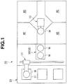
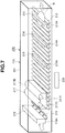
- a substrate processing device 10 of an embodiment 1 has a substrate supply/discharge unit 20, a substrate storing buffer unit 30, a plurality of substrate cleaning chambers 40, and a substrate drying chamber 60 arranged in an out-dedicated buffer 32 which is employed in the substrate storing buffer unit 30 and will be described later.
- a transporting robot 11 is arranged between the substrate supply/discharge unit 20 and the substrate storing buffer unit 30, and a transporting robot 12 is arranged between the substrate storing buffer unit 30 and the substrate cleaning chamber 40.
- a plurality of substrate accommodation cassettes 21 can be supplied to and discharged from the substrate supply/discharge unit 20.
- the substrate accommodation cassette 21 which has accommodated a plurality of substrates W such as unprocessed wafers, liquid crystal substrates or the like is supplied to the substrate supply/discharge unit 20, and will be discharged from the substrate supply/discharge unit 20 together with the accommodated substrates W which are processed in the substrate cleaning chamber 40 and the substrate drying chamber 60.
- the unprocessed substrates W are successively taken out by the transporting robot 11 from multi-level accommodation shelves of the substrate accommodation cassette 21 in the substrate supply/discharge unit 20, are supplied to an in-dedicated buffer (not illustrated) to be described later in the substrate storing buffer unit 30, further are taken out by the transporting robot 12 from the in-dedicated buffer of the substrate storing buffer unit 30, and are supplied to the substrate cleaning chamber 40 for cleaning.
- the transporting robot 12 takes out the substrate W cleaned in the substrate cleaning chamber 40 from the substrate cleaning chamber 40, and feeds it to the out-dedicated buffer 32 to be described later of the substrate storing buffer unit 30.
- the transporting robot 11 takes the substrates W after being dried in the substrate drying chamber 60 in the out-dedicated buffer 32 of the substrate storing buffer unit 30, and successively discharges the substrates W to the empty accommodation shelves in the substrate accommodation cassette 21 of the substrate supply/discharge unit 20.
- the substrate accommodation cassette 21 filled with the processed substrates W is transported from the substrate supply/discharge unit 20.
- the substrate storing buffer unit 30 has the plurality of in-dedicated buffers arranged in the multi-shelf form for storing the unprocessed substrates W, and has the plurality of out-dedicated buffers 32 arranged in the multi-shelf form for storing the substrates W cleaned in the substrate cleaning chamber 40.
- the substrate drying chamber 60 is arranged in the out-dedicated buffer 32 as will be described later.
- the in-dedicated buffer and the out-dedicated buffer 32 may not have the multi-shelf form.
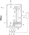
- the substrate cleaning chamber 40 includes, as illustrated in FIG. 2 , a processing box 41 forming a processing chamber, a cup 42 arranged in the processing box 41, a table 43 carrying the substrate W in a horizontal position in the cup 42, a rotation mechanism 44 rotating the table 43 in a horizontal plane, and a solvent suction discharging unit 45 that can vertically move around the table 43.
- the substrate cleaning chamber 40 further includes a chemical solution supply unit 46 supplying a chemical solution to a surface of the substrate W on the table 43, a cleaning liquid supply unit 47 supplying a cleaning liquid to the surface of the substrate W on the table 43, a solvent supply unit 48 supplying a volatile solvent, and a controller 50 controlling the various units.
- the processing box 41 has a substrate inlet/outlet opening 41A opening at a portion of its peripheral wall.
- a shutter 41B can close and open the substrate inlet/outlet opening 41A.
- the cup 42 has a cylindrical form, surrounds the periphery of the table 43, and accommodates it.
- the cup 42 has a peripheral wall having an upper portion tapered to converge upward, and has an opening to expose the substrate W on the table 43 upward.
- This cup 42 receives the chemical solution and cleaning liquid that flow or disperse from the rotating substrate W.
- the cup 42 is provided at its bottom with a discharge pipe (not illustrated) for discharging the received chemical solution and cleaning liquid.
- the table 43 is positioned near a center of the cup 42, and is rotatable in the horizontal plane.
- the table 43 has a plurality of support members 43A such as pins, which removably hold the substrate W such as a wafer or a liquid crystal substrate.
- the rotation mechanism 44 has a rotation axis coupled to the table 43, a motor serving as a drive source for rotating the rotation shaft, and others (not illustrated), and rotates the table 43 by the driving of the motor through the rotation shaft.
- the rotation mechanism 44 is electrically connected to the controller 50, which controls the drive of the rotation mechanism 44.
- the solvent suction discharging unit 45 includes a solvent absorbing port 45A having an annular opening surrounding the periphery of the table 43.
- the solvent suction discharging unit 45 has an elevator mechanism (not illustrated) for vertically moving the solvent absorbing port 45A, and vertically moves the solvent absorbing port 45A between a standby position where the solvent absorbing port 45A is positioned lower than the table surface of the table 43 and an operation position where the solvent absorbing port 45A is positioned around the substrate W held by the table 43.
- the solvent absorbing port 45A absorbs and receives the volatile solvent dispersed from the rotating substrate W.
- the solvent absorbing port 45A is connected to an exhaust fan or a vacuum pump (not illustrated) for absorbing the volatile solvent as well as an exhaust pipe (not illustrated) for discharging the volatile solvent that is absorbed and received.
- the chemical solution supply unit 46 has a nozzle 46A discharging the chemical solution obliquely to the surface of the substrate W on the table 43, and supplies the chemical solution such as APM (Ammonia and hydrogen Peroxide Mixture) for resist peeling processing to the surface of the substrate W on the table 43 through the nozzle 46A.
- the nozzle 46A is attached to an upper portion of the peripheral wall of the cup 42, and its angle, discharging flow velocity and others are adjusted to supply the chemical solution to the vicinity of the surface center of the substrate W.
- the chemical solution supply unit 46 is electrically connected to the controller 50, which controls the drive of the chemical solution supply unit 46.
- the chemical solution supply unit 46 includes a tank storing the chemical solution, a pump serving as a drive source, a valve serving as a regulator valve regulating a supply rate, and others, although not illustrated.
- the cleaning liquid supply unit 47 has a nozzle 47A discharging the cleaning liquid obliquely to the surface of the substrate W on the table 43, and supplies the cleaning liquid such as pure water (ultrapure water) for cleaning processing to the surface of the substrate W on the table 43 through the nozzle 47A.
- the nozzle 47A is attached to the upper portion of the peripheral wall of the cup 42, and its angle, discharging flow velocity and others are adjusted to supply the cleaning liquid to the vicinity of the surface center of the substrate W.
- the cleaning liquid supply unit 47 is electrically connected to the controller 50, which controls the drive of the cleaning liquid supply unit 47.
- the cleaning liquid supply unit 47 includes a tank storing the cleaning liquid, a pump serving as a drive source, and a valve serving as a regulator valve regulating a supply rate, although not illustrated.
- the solvent supply unit 48 has a nozzle 48A discharging the volatile solvent obliquely to the surface of the substrate W on the table 43, and supplies the volatile solvent such as IPA to the surface of the substrate W on the table 43 through the nozzle 48A.
- the solvent supply unit 48 supplies the volatile solvent to the surface of the substrate W cleaned with the cleaning liquid supplied by the cleaning liquid supply unit 47, and replaces the cleaning liquid on the surface of the substrate W with the volatile solvent.
- the nozzle 48A is attached to the upper portion of the peripheral wall of the cup 42, and its angle, discharging flow velocity and others are adjusted to supply the volatile solvent to the vicinity of the surface center of the substrate W.
- the solvent supply unit 48 is electrically connected to the controller 50, which controls the drive of the solvent supply unit 48.
- the solvent supply unit 48 includes a tank storing the volatile solvent, a pump serving as a drive source, and a valve serving as a regulator valve regulating a supply rate, although not illustrated.
- univalent alcohols such as ethanol, and ethers such as diethyl ether and ethyl methyl ether as well as ethylene carbonate and the like may be used as the volatile solvent.
- the volatile solvent is preferably water-soluble.
- the controller 50 includes a microcomputer that centrally controls the various portions, and a storage storing substrate processing information relating to the substrate processing, various kinds of programs and others.
- the controller 50 controls, based on the substrate processing information and various programs, the rotation mechanism 44, solvent suction discharging unit 45, chemical solution supply unit 46, cleaning liquid supply unit 47, solvent supply unit 48 and others, and controls the supplying of the chemical solution by the chemical solution supply unit 46, supplying of the cleaning liquid by the cleaning liquid supply unit 47, supplying of the volatile solvent by the solvent supply unit 48 performed on the surface of the substrate W on the rotating table 43, and others.
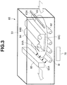
- the substrate drying chamber 60 is arranged for each of the multi-level shelves in the out-dedicated buffer 32 of the substrate storing buffer unit 30, and includes, as illustrated in FIG. 3 , a tunnel-like processing box 61 forming a processing chamber, and a plurality of transport rollers 62 forming a transporting unit in the processing box 61. Further, the substrate drying chamber 60 includes a gas supply unit 63 supplying a gas to the surface of the substrate W on the transport rollers 62, a heating unit 64 for heating the substrate W to which the volatile solvent is supplied in the substrate cleaning chamber 40, a suction drying unit 65 for drying the surface of the substrate W heated by the heating unit 64, and a controller 70 controlling various portions. Although the transport rollers 62 are likewise arranged downstream to the position where the suction drying unit 65 is arranged, these are not illustrated in FIG. 3 .
- the processing box 61 has a tunnel-like form.
- the substrate W which is subjected to the cleaning processing and is taken out from the substrate cleaning chamber 40 by the transporting robot 12 is fed through an upstream opening of the processing box 61, and the substrate W which is subjected to the drying processing by the substrate drying chamber 60 is discharged by the transporting robot 11 through a downstream opening of the processing box 61.
- the transport rollers 62 are driven to rotate by a drive unit such as a motor (not illustrated), and transport the substrate W fed through the upstream opening of the processing box 61 through a lower transport passage of the gas supply unit 63, heating unit 64, and suction drying unit 65 toward the downstream opening.
- the transport rollers 62 are electrically connected to the controller 70, which controls the drive of the transport rollers 62.
- the gas supply unit 63 is located upstream, in the substrate transporting direction of the transport rollers 62, to the heating unit 64, and is arranged above the transport rollers 62.
- the gas supply unit 63 has a slit-like nozzle 63A obliquely discharging a gas to the widthwise full area of the surface of the substrate W on the transport rollers 62, and supplies through the nozzle 63A a gas such as nitrogen gas to the surface of the substrate W on the transport rollers 62 to form a nitrogen gas atmosphere in the space on the surface of the substrate W in the processing box 61.
- the nozzle 63A is attached to the processing box 61, and its angle, discharging flow velocity and others are adjusted to supply the gas to the widthwise full area of the surface of the substrate W.
- This gas supply unit 63 is electrically connected to the controller 70, which controls the drive of the gas supply unit 63.
- the gas supply unit 63 includes a tank storing the gas, a valve serving as a regulator valve regulating a supply rate, and others, although not illustrated. The supply rate of the gas is adjusted such that the gas discharged from the nozzle 63A may not completely dry the volatile solvent already supplied to the surface of the substrate W.
- an inert gas such as argon gas, carbon dioxide gas or helium gas other than nitrogen gas can be used. Since the insert gas is supplied to the surface of the substrate W, the oxygen on the surface of the substrate W can be removed, and production of watermarks can be prevented.
- the heating unit 64 has a plurality of lamps 64A, and is arranged above the transport rollers 62. When each lamp 64A is turned on, it irradiates the surface of the substrate W on the transport rollers 62 with light. The heating unit 64 heats the substrate W by irradiating the widthwise full area of the surface of the substrate W with the light emitted through a transparent cover 64C from the lamps 64A arranged in a lamp casing 64B attached to the processing box 61. This heating unit 64 is electrically connected to the controller 70, which controls the drive of the heating unit 64.
- the heating unit 64 may be formed of the plurality of lamps 64A, e.g., of a straight-tube type arranged in parallel, or the plurality of lamps 64A of a light ball type arranged in an array fashion.
- the lamp 64A may be, for example, a halogen lamp, xenon flash lamp or the like.
- the heating by the heating unit 64 causes liquid A1 of the volatile solvent in contact with a pattern P on the surface of the substrate W to start evaporation earlier than the liquid A1 of the volatile solvent on the other portion. More specifically, in the liquid A1 of the volatile solvent supplied to the surface of the substrate W, only the liquid in contact with the surface of the substrate W is rapidly heated to attain the gas phase. Thereby, gasification (boiling) of the liquid A1 of the volatile solvent forms a gas layer, namely a gas layer A2 of the volatile solvent taking a thin-film-like form around the pattern P on the surface of the substrate W. Therefore, the liquid A1 of the volatile solvent between the neighboring patterns P is pushed onto the surface of the substrate W by the gas layer A2, and its own surface tension changes the liquid A1 into many droplets.
- the suction drying unit 65 is located downstream, in the substrate transporting direction of the transport rollers 62, from the heating unit 64 and is arranged above the transport rollers 62.
- the suction drying unit 65 is attached to the processing box 61, and has a solvent suction port 65A of a slit-like form opening toward the widthwise full area of the surface of the substrate W on the transport rollers 62.
- the suction drying unit 65 applies a suction force provided to the solvent suction port 65A to the widthwise full area of the surface of the substrate W, and dries the surface of the substrate W by absorbing and removing the droplets of the volatile solvent produced on the surface of the substrate W by the heating operation of the heating unit 64 as described above.
- This suction drying unit 65 is electrically connected to the controller 70, which controls the drive of the suction drying unit 65.
- a vacuum pump (not illustrated) for absorbing the droplets of the volatile solvent is connected to the solvent suction port 65A.
- a blow-off drying unit may be used together with the suction drying unit 65.
- This blow-off drying unit blows and removes the droplets of the volatile solvent produced on the surface of the substrate W by an injected gas to dry the surface of the substrate W.
- the gas supply unit 63 described above may also be used as this blow-off drying unit.
- FIG. 4 illustrates a modification of the substrate drying chamber 60.
- This modification is provided with a blow-off drying unit 67 injecting an inert gas such as nitrogen gas to a downstream side of the heating unit 64 in the substrate transporting direction of the transport rollers 62 when an atmosphere forming unit (not illustrated) controls the space on the surface of the substrate W in the processing box 61 to keep a nitrogen gas atmosphere, and is configured to blow and remove the droplets of the volatile solvent produced on the surface of the substrate W by the blow-off drying unit 67.
- an atmosphere forming unit not illustrated
- the controller 70 includes a microcomputer centrally controlling various portions, and a storage storing the substrate processing information and various programs relating to the substrate processing.
- the controller 70 controls the gas supply unit 63, heating unit 64, suction drying unit 65 and others based on the substrate processing information and the various programs, and further controls the gas supply unit 63, heating by the heating unit 64, suction force of the suction drying unit 65, and others effected on the surface of the substrate W on the transport rollers 62.
- the embodiment achieves the following operation and effect.
- a substrate processing device 100 of an Embodiment 2 the substrate cleaning chamber 40 in the substrate processing device 10 of Embodiment 1 is replaced with a substrate processing chamber 110, the substrate drying chamber 60 is removed from the out-dedicated buffer 32 of the substrate storing buffer unit 30 in Embodiment 1, and the substrate processing chamber 110 intensively has the functions of the substrate cleaning chamber 40 and the substrate drying chamber 60 in Embodiment 1.
- the substrate processing chamber 110 will now be described.
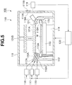
- the substrate processing chamber 110 includes, as illustrated in FIG. 5 , a processing box 111 forming a processing chamber, a cup 112 arranged in the processing box 111, a table 113 supporting a substrate W horizontal in the cup 112, a rotation mechanism 114 rotating the table 113 in a horizontal plane, and a solvent suction discharging unit 115 which moves vertically in an area around the table 113.
- the substrate processing chamber 110 has a chemical solution supply unit 116 supplying a chemical solution to a surface of the substrate W on the table 113, a cleaning liquid supply unit 117 supplying a cleaning liquid to the surface of the substrate W on the table 113, a solvent supply unit 118 supplying a volatile solvent, a gas supply unit 119 for supplying a gas, a heating unit 121 heating the substrate W supplied with the volatile solvent, and a controller 130 controlling various portions.
- the solvent suction discharging unit 115 not only absorbs and receives the volatile solvent dispersed from a rotating substrate W, but also has a function of absorbing and removing the droplets of the volatile solvent produced on the surface of the substrate W by the heating operation of the heating unit 121, which is not employed in the solvent suction discharging unit 45. Accordingly, the solvent suction discharging unit 115 has a suction power that can absorb the droplets of the volatile solvent such as droplets of the IPA present on the surface of the substrate W.
- the gas supply unit 119 has a nozzle 119A discharging a gas obliquely to the surface of the substrate W on the table 113, and supplies an inert gas, e.g., nitrogen gas to the surface of the substrate W on the table 113 through the nozzle 119A so that a nitrogen gas atmosphere is formed in the space above the surface of the substrate W in the processing box 111.
- the specific structure of the gas supply unit 119 is substantially the same as that of the gas supply unit 63 arranged in the substrate drying chamber 60 of Embodiment 1.
- the nozzle 119A may not have a slit-like form, and may be a circular nozzle.
- the heating unit 121 has a plurality of lamps 121A, is arranged above the table 113, and irradiates the surface of the substrate W on the table 113 with light when each lamp 121A is turned on.
- This heating unit 121 is configured to be moved vertically (ascent/descent direction) by a moving unit 121B, and can move between an irradiation position close to the cup 112 (and close to the surface of the substrate W as indicated by solid line in FIG. 5 ) and a standby position spaced from the cup 112 by a predetermined distance (and spaced from the surface of the substrate W as indicated by alternate long and short dashed lines in FIG. 5 ).
- the heating unit 121 can be positioned in the standby position so that adhesion of the liquid used for the processing to the heating unit 121 is prevented.
- the heating unit 121 is positioned in the standby position so that the heating unit 121 is prevented from impeding the entry of the substrate W.
- the heating unit 121 may be lowered either after or before turning on the lamps.
- the heating unit 121 has the substantially same specific structures as the heating unit 64 arranged in the substrate drying chamber 60 of Embodiment 1.
- the heating by the heating unit 121 causes liquid A1 of the volatile solvent in contact with a pattern P on the surface of the substrate W to start evaporation earlier than the liquid A1 of the volatile solvent on the other portion similarly to the heating by the heating unit 64 of Embodiment 1. More specifically, in the liquid A1 of the volatile solvent supplied to the surface of the substrate W, only the portion in contact with the surface of the substrate W is rapidly heated to attain the gas phase. Thereby, gasification (boiling) of the liquid A1 of the volatile solvent forms a gas layer, namely a gas layer A2 of the volatile solvent taking a thin-film-like form around the pattern P on the surface of the substrate W. Therefore, the liquid A1 of the volatile solvent between the neighboring patterns P is pushed onto the surface of the substrate W by the gas layer A2, and its own surface tension changes the liquid A1 into many droplets.
- the controller 130 Before taking out the substrate W in the above (7), the controller 130 turns off the lamps 121A of the heating unit 121, and positions it in the standby position. Thereby, the heating unit 121 does not impede the take-out operation of the substrate W.
- the substrate processing device 100 of Embodiment 2 can achieve substantially the same operation and effect as the substrate processing device 10 of Embodiment 1.
- the order of the processes (4) and (5) may be inverted.
- a substrate processing device 200 of an embodiment 3 includes a tunnel-like processing box 211 forming a substrate processing chamber 210, and a plurality of transport rollers 212 forming a transporting unit in the processing box 211 and transporting substrates W. Further, the substrate processing device 200 includes a chemical solution supply unit 213 supplying a chemical solution to a surface of the substrate W on the transport rollers 212, a cleaning liquid supply unit 214 supplying a cleaning liquid to the surface of the substrate W on the transport rollers 212, a solvent supply unit 215 supplying a volatile solvent, a gas supply unit 216 supplying a gas to the surface of the substrate W on the transport rollers 212, a heating unit 217 heating the substrate W supplied with the volatile solvent, a suction drying unit 218 for drying the surface of the substrate W heated by the heating unit 217, and a controller 220 controlling the various portions.
- a chemical solution supply unit 213 supplying a chemical solution to a surface of the substrate W on the transport rollers 212
- the processing box 211 has a tunnel-like form. It receives the unprocessed substrate W through an upstream opening, and discharges the substrate W cleaned and dried in the substrate processing chamber 210 through a downstream opening of the processing box 211.
- the transport rollers 212 are driven to rotate by a drive unit such as a motor (not illustrated), and transport the substrate W fed through the upstream opening of the processing box 211 toward the downstream opening along a lower transport passage of the chemical solution supply unit 213, cleaning liquid supply unit 214, solvent supply unit 215, gas supply unit 216, heating unit 217, and suction drying unit 218.
- the transport rollers 212 are electrically connected to the controller 220, which controls the drive thereof.
- the chemical solution supply unit 213, cleaning liquid supply unit 214 and solvent supply unit 215 are arranged in the transporting direction of the substrate W and successively neighbor to each other. However, the arrangement pitches thereof are larger than a length of the transported substrate W in the transporting direction, and are appropriately set according to liquid supply rates of the respective supply unit.
- the chemical solution supply unit 213 has a slit-like nozzle 213A discharging a chemical solution downward to the widthwise full area of the surface of the substrate W on the transport rollers 212, and supplies the chemical solution such as APM (Ammonia and hydrogen Peroxide water Mixture) for resist-peeling processing to the surface of the substrate W on the transport rollers 212 through the nozzle 213A.
- the chemical solution supply unit 213 is electrically connected to the controller 220, which controls the drive thereof.
- the chemical solution supply unit 213 includes a tank storing the chemical solution, a pump serving as a drive source, a valve serving as a regulator valve regulating a supply rate, and others, although not illustrated.
- the cleaning liquid supply unit 214 has a slit-like nozzle 214A discharging the cleaning liquid downward to the widthwise full area of the surface of the substrate W on the transport rollers 212, and supplies the cleaning liquid such as pure water (ultrapure water) for cleaning processing to the surface of the substrate W on the transport rollers 212 through the nozzle 214A.
- the cleaning liquid supply unit 214 is electrically connected to the controller 220, which controls the drive thereof.
- the cleaning liquid supply unit 214 includes a tank storing the cleaning liquid, a pump serving as a drive source, a valve serving as a regulator valve regulating a supply rate, and others, although not illustrated.
- the solvent supply unit 215 has a slit-like nozzle 215A discharging the volatile solvent downward to the widthwise full area of the surface of the substrate W on the transport rollers 212, and supplies the volatile solvent such as IPA to the surface of the substrate W on the transport rollers 212 through the nozzle 215A.
- the solvent supply unit 215 supplies the volatile solvent to the surface of the substrate W already supplied with the cleaning liquid from the cleaning liquid supply unit 214, and replaces the cleaning liquid on the surface of the substrate W with the volatile solvent.
- the solvent supply unit 215 is electrically connected to the controller 220, which controls the drive thereof.
- the solvent supply unit 215 includes a tank storing the volatile solvent, a pump serving as a drive source, a valve serving as a regulator valve regulating a supply rate, and others, although not illustrated.
- the gas supply unit 216 is located upstream, in the substrate transporting direction of the transport rollers 212, to the heating unit 217, and is arranged above the transport rollers 212.
- the gas supply unit 216 has a slit-like nozzle 216A obliquely discharging a gas to the widthwise full area of the surface of the substrate W on the transport rollers 212, and supplies through the nozzle 216A a gas, e.g., an inert gas such as nitrogen gas to the surface of the substrate W on the transport rollers 212 to form a nitrogen gas atmosphere in the space on the surface of the substrate W in the processing box 211.
- a gas e.g., an inert gas such as nitrogen gas
- the nozzle 216A is attached to the processing box 211, and its angle, discharging flow velocity and others are adjusted to supply the gas to the widthwise full area of the surface of the substrate W.
- This gas supply unit 216 is electrically connected to the controller 220, which controls the drive of the gas supply unit 216.
- the gas supply unit 216 includes a tank storing the gas, a valve serving as a regulator valve regulating a supply rate, and others, although not illustrated.
- the heating unit 217 has a plurality of lamps 217A, is arranged above the transport rollers 212, and each of the lamps 217A is turned on to irradiate the surface of the substrate W on the transport rollers 212 with light.
- the heating unit 217 heats the substrate W by irradiating the widthwise full area of the surface of the substrate W with the light emitted through a transparent cover 217C from the lamps 217A arranged in a lamp casing 217B attached to the processing box 211.
- This heating unit 217 is electrically connected to the controller 220, which controls the drive of the heating unit 217.
- the heating by the heating unit 217 causes liquid A1 of the volatile solvent in contact with a pattern P on the surface of the substrate W to start evaporation earlier than the liquid A1 of the volatile solvent on the other portion.
- gasification (boiling) of the liquid A1 of the volatile solvent forms a gas layer, namely a gas layer A2 of the volatile solvent taking a thin-film-like form around the pattern P on the surface of the substrate W. Therefore, the liquid A1 of the volatile solvent between the neighboring patterns P is pushed onto the surface of the substrate W by the gas layer A2, and its own surface tension changes the liquid A1 into many droplets.
- the suction drying unit 218 is located downstream, in the substrate transporting direction of the transport rollers 212, from the heating unit 217 and is arranged above the transport rollers 212.
- the suction drying unit 218 is attached to the processing box 211 and has a solvent suction port 218A of a slit-like form opening toward the widthwise full area of the surface of the substrate W on the transport rollers 212.
- the suction drying unit 218 applies a suction force provided to the solvent suction port 218A to the widthwise full area of the surface of the substrate W, and dries the surface of the substrate W by absorbing and removing the droplets of the volatile solvent produced on the surface of the substrate W by the heating operation of the heating unit 217 as described above.
- This suction drying unit 218 is electrically connected to the controller 220, which controls the drive of the suction drying unit 218.
- a vacuum pump (not illustrated) for absorbing the droplets of the volatile solvent is connected to the solvent suction port 218A.
- a blow-off drying unit may be used together with the suction drying unit 218.
- This blow-off drying unit blows and removes the droplets of the volatile solvent produced on the surface of the substrate W by an injection gas to dry the surface of the substrate W.
- the gas supply unit 216 described above may also be used as this blow-off drying unit.
- FIG. 7 illustrates a modification of the substrate processing chamber 210.
- This modification is provided with a blow-off drying unit 219 injecting an inert gas such as nitrogen gas to a downstream side of the heating unit 217 in the substrate transporting direction of the transport rollers 212 when an atmosphere forming unit (not illustrated) controls the space on the surface of the substrate W in the processing box 211 to keep a nitrogen gas atmosphere, and is configured to blow and remove the droplets of the volatile solvent produced on the surface of the substrate W by the blow-off drying unit 219.
- an atmosphere forming unit not illustrated
- the embodiment achieves the following operation and effect.
- the volatile solvent on the substrate may dry while the substrate W is being transported from the substrate cleaning chamber 40 to the substrate drying chamber 60. Therefore, a supply device of the volatile solvent may be arranged in an opening upstream to the processing box 61 in the substrate drying chamber 60 illustrated in FIGS. 3 and 4 , the substrate W already supplied with the cleaning liquid in the substrate cleaning chamber 40 may be transported to the substrate drying chamber 60, and the volatile solvent may be supplied to the surface of the substrate W when the substrate W is fed into the substrate drying chamber 60.
- the transport roller 62 or 212 transports the substrate W.
- the substrate W may be transported while clamping the substrate W with a clamper instead of the roller.
- the chemical solution, cleaning liquid, volatile solvent and the like are successively supplied to the substrate W while the substrate W is being transported.
- the transport rollers 212 or the like are used for transporting the substrate W
- the transported substrate W is successively stopped at positions where a central portion, in the transporting direction, of the substrate is opposed to the nozzles 213A, 214A, and 215A, discharging the chemical solution, cleaning liquid and volatile solvent, respectively, and the respective nozzles supply the processing liquids such as the chemical solution to the stopped substrate W.
- the heating of the substrate W by the heating unit 217 may be performed while the substrate W is stopped.
- the out-dedicated buffers 32 may be arranged in multiple stages, and the substrate drying chamber 60 may be arranged in each stage. In this structure, the drying processing can take place in parallel in the respective stages so that the substrate processing capacity can be increased.
- the out-dedicated buffer 32 may be arranged in one stage instead of the multiple stages, and the substrate drying chamber may be arranged in this stage.
- the operation of supplying the inert gas such as nitrogen gas by each of the gas supply units 63, 119, 216 is configured to start after the substrate W is positioned in the supply position, but the operation may start before the positioning.
- the heating of the substrate W by the heating unit 121 may be performed in a state where the pressure in the processing box 111 is reduced. This lowers the boiling point of the volatile solvent such as IPA in the processing box 111, and causes boiling at a temperature lower than that in the atmospheric pressure so that the heat damage to the substrate can be reduced.
- the volatile solvent such as IPA
- the supply of the volatile solvent such as IPA to the substrate W starts after the supply of the cleaning liquid to the substrate W stops.
- the supply of the volatile solvent may start while the supply of the cleaning liquid to the substrate W still continues in a final period of the cleaning with the cleaning liquid.
- this can be carried out by setting the arrangement pitches between the cleaning liquid supply unit 214 and the solvent supply unit 215 to smaller pitches than a length of the transported substrate W in the transporting direction.
- a gas to be supplied can be a gas that is heated.
- an inert gas such as dried air or nitrogen gas into the processing boxes 41, 111, 211 before supplying the volatile solvent such as the IPA to the substrate W.
- the invention can provide the substrate processing device and the substrate processing method that instantaneously dry the liquid on the surface during drying of the substrate.
Landscapes
- Cleaning Or Drying Semiconductors (AREA)
- Cleaning By Liquid Or Steam (AREA)
- Drying Of Solid Materials (AREA)
- Exposure Of Semiconductors, Excluding Electron Or Ion Beam Exposure (AREA)
Applications Claiming Priority (2)
| Application Number | Priority Date | Filing Date | Title |
|---|---|---|---|
| JP2013054559 | 2013-03-18 | ||
| JP2014028998A JP6351993B2 (ja) | 2013-03-18 | 2014-02-18 | 基板処理装置及び基板処理方法 |
Publications (3)
| Publication Number | Publication Date |
|---|---|
| EP2782127A2 EP2782127A2 (en) | 2014-09-24 |
| EP2782127A3 EP2782127A3 (en) | 2014-10-29 |
| EP2782127B1 true EP2782127B1 (en) | 2017-01-25 |
Family
ID=50732754
Family Applications (1)
| Application Number | Title | Priority Date | Filing Date |
|---|---|---|---|
| EP14160174.0A Not-in-force EP2782127B1 (en) | 2013-03-18 | 2014-03-17 | Substrate processing device and substrate processing method |
Country Status (6)
| Country | Link |
|---|---|
| US (1) | US10276406B2 (enExample) |
| EP (1) | EP2782127B1 (enExample) |
| JP (1) | JP6351993B2 (enExample) |
| KR (1) | KR101602554B1 (enExample) |
| CN (1) | CN104064496B (enExample) |
| TW (1) | TWI536445B (enExample) |
Families Citing this family (9)
| Publication number | Priority date | Publication date | Assignee | Title |
|---|---|---|---|---|
| JP6300314B2 (ja) * | 2014-03-26 | 2018-03-28 | 株式会社Screenホールディングス | 基板処理装置 |
| KR102267508B1 (ko) | 2014-02-27 | 2021-06-22 | 가부시키가이샤 스크린 홀딩스 | 기판 처리 장치 및 기판 처리 방법 |
| JP6226297B2 (ja) * | 2014-03-26 | 2017-11-08 | 株式会社Screenホールディングス | 基板処理装置 |
| JP6304592B2 (ja) * | 2014-03-25 | 2018-04-04 | 株式会社Screenホールディングス | 基板処理方法および基板処理装置 |
| KR101877112B1 (ko) * | 2015-01-23 | 2018-07-10 | 가부시키가이샤 스크린 홀딩스 | 기판 처리 방법 및 기판 처리 장치 그리고 유체 노즐 |
| JP6748524B2 (ja) * | 2015-09-30 | 2020-09-02 | 芝浦メカトロニクス株式会社 | 基板処理装置及び基板処理方法 |
| JP6829639B2 (ja) * | 2017-03-28 | 2021-02-10 | Eneos株式会社 | W/oエマルジョン洗浄液を使用する洗浄方法 |
| JP7285692B2 (ja) * | 2019-05-17 | 2023-06-02 | 東京エレクトロン株式会社 | 乾燥装置、基板処理システム、および乾燥方法 |
| JP7726653B2 (ja) * | 2021-03-31 | 2025-08-20 | 芝浦メカトロニクス株式会社 | 基板乾燥装置及び基板処理装置 |
Family Cites Families (39)
| Publication number | Priority date | Publication date | Assignee | Title |
|---|---|---|---|---|
| JPS6292325A (ja) | 1985-10-17 | 1987-04-27 | Nec Corp | ウエハ−乾燥装置 |
| US5745946A (en) * | 1994-07-15 | 1998-05-05 | Ontrak Systems, Inc. | Substrate processing system |
| JPH09148297A (ja) * | 1995-11-24 | 1997-06-06 | Hitachi Ltd | 基板の乾燥方法およびこれを用いる乾燥装置およびこれを用いる半導体装置の製造方法 |
| US5980637A (en) | 1996-12-20 | 1999-11-09 | Steag Rtp Systems, Inc. | System for depositing a material on a substrate using light energy |
| JP3171807B2 (ja) | 1997-01-24 | 2001-06-04 | 東京エレクトロン株式会社 | 洗浄装置及び洗浄方法 |
| JP3330300B2 (ja) | 1997-02-28 | 2002-09-30 | 東京エレクトロン株式会社 | 基板洗浄装置 |
| KR100271764B1 (ko) | 1997-12-24 | 2000-12-01 | 윤종용 | 반도체장치 제조용 현상 장치 및 그의 제어방법 |
| JPH11340187A (ja) | 1998-05-28 | 1999-12-10 | Matsushita Electric Ind Co Ltd | 洗浄乾燥装置および洗浄乾燥方法 |
| JPH11354487A (ja) | 1998-06-03 | 1999-12-24 | Dainippon Screen Mfg Co Ltd | 基板乾燥装置および基板乾燥方法 |
| JP3250154B2 (ja) | 1999-03-31 | 2002-01-28 | 株式会社スーパーシリコン研究所 | 半導体ウエハ製造装置 |
| ATE476754T1 (de) | 1999-05-20 | 2010-08-15 | Kaneka Corp | Verfahren und vorrichtung zur herstellung eines halbleiterbauelements |
| AT407680B (de) * | 1999-06-04 | 2001-05-25 | Sez Semiconduct Equip Zubehoer | Verfahren und vorrichtung zum trocknen von scheibenförmigen gegenständen |
| DE10030431A1 (de) * | 2000-06-21 | 2002-01-10 | Karl Suess Kg Praez Sgeraete F | Verfahren und Vorrichtung zum Reinigen und/oder Bonden von Substraten |
| WO2003041131A2 (en) * | 2001-11-02 | 2003-05-15 | Applied Materials, Inc. | Single wafer dryer and drying methods |
| JP4056858B2 (ja) | 2001-11-12 | 2008-03-05 | 東京エレクトロン株式会社 | 基板処理装置 |
| US6843855B2 (en) | 2002-03-12 | 2005-01-18 | Applied Materials, Inc. | Methods for drying wafer |
| JP2004259734A (ja) | 2003-02-24 | 2004-09-16 | Dainippon Screen Mfg Co Ltd | 基板処理装置および基板処理方法 |
| TW200633033A (en) | 2004-08-23 | 2006-09-16 | Koninkl Philips Electronics Nv | Hot source cleaning system |
| US7642205B2 (en) | 2005-04-08 | 2010-01-05 | Mattson Technology, Inc. | Rapid thermal processing using energy transfer layers |
| KR100696378B1 (ko) | 2005-04-13 | 2007-03-19 | 삼성전자주식회사 | 반도체 기판을 세정하는 장치 및 방법 |
| JP4527660B2 (ja) * | 2005-06-23 | 2010-08-18 | 東京エレクトロン株式会社 | 基板処理方法及び基板処理装置 |
| JP2008034779A (ja) | 2006-06-27 | 2008-02-14 | Dainippon Screen Mfg Co Ltd | 基板処理方法および基板処理装置 |
| KR100816740B1 (ko) * | 2006-08-30 | 2008-03-27 | 세메스 주식회사 | 기판 처리 장치 및 방법 |
| JP5043406B2 (ja) * | 2006-11-21 | 2012-10-10 | 大日本スクリーン製造株式会社 | 基板乾燥方法および基板乾燥装置 |
| JP2009076856A (ja) | 2007-08-28 | 2009-04-09 | Dainippon Screen Mfg Co Ltd | 基板処理装置 |
| ES2593279T3 (es) | 2007-08-29 | 2016-12-07 | Methylgene Inc. | Procesos e intermedios para preparar inhibidores de cinasa heterocíclicos condensados |
| DE102007058002B4 (de) | 2007-12-03 | 2016-03-17 | Mattson Thermal Products Gmbh | Vorrichtung zum thermischen Behandeln von scheibenförmigen Halbleitersubstraten |
| JP4601079B2 (ja) * | 2007-12-17 | 2010-12-22 | 東京エレクトロン株式会社 | 基板処理方法及び基板処理装置 |
| JP5413016B2 (ja) | 2008-07-31 | 2014-02-12 | 東京エレクトロン株式会社 | 基板の洗浄方法、基板の洗浄装置及び記憶媒体 |
| JP5140641B2 (ja) * | 2009-06-29 | 2013-02-06 | 株式会社荏原製作所 | 基板処理方法及び基板処理装置 |
| CN101718487B (zh) * | 2009-12-04 | 2013-07-31 | 有研半导体材料股份有限公司 | 一种硅片清洗后的快速干燥方法和装置 |
| JP5146522B2 (ja) | 2010-11-26 | 2013-02-20 | 東京エレクトロン株式会社 | 基板処理装置、基板処理方法及び記憶媒体 |
| JP5254308B2 (ja) | 2010-12-27 | 2013-08-07 | 東京エレクトロン株式会社 | 液処理装置、液処理方法及びその液処理方法を実行させるためのプログラムを記録した記録媒体 |
| US20120260517A1 (en) | 2011-04-18 | 2012-10-18 | Lam Research Corporation | Apparatus and Method for Reducing Substrate Pattern Collapse During Drying Operations |
| WO2012165377A1 (ja) | 2011-05-30 | 2012-12-06 | 東京エレクトロン株式会社 | 基板処理方法、基板処理装置および記憶媒体 |
| JP2012250230A (ja) | 2011-06-02 | 2012-12-20 | Tokyo Ohka Kogyo Co Ltd | 加熱装置、塗布装置及び加熱方法 |
| KR101329304B1 (ko) | 2011-07-29 | 2013-11-14 | 세메스 주식회사 | 기판처리장치 및 기판처리방법 |
| JP5686261B2 (ja) | 2011-07-29 | 2015-03-18 | セメス株式会社SEMES CO., Ltd | 基板処理装置及び基板処理方法 |
| JP6000822B2 (ja) | 2012-11-26 | 2016-10-05 | 東京エレクトロン株式会社 | 基板洗浄方法および基板洗浄システム |
-
2014
- 2014-02-18 JP JP2014028998A patent/JP6351993B2/ja active Active
- 2014-03-14 KR KR1020140030244A patent/KR101602554B1/ko active Active
- 2014-03-14 US US14/212,899 patent/US10276406B2/en active Active
- 2014-03-17 TW TW103109914A patent/TWI536445B/zh active
- 2014-03-17 EP EP14160174.0A patent/EP2782127B1/en not_active Not-in-force
- 2014-03-18 CN CN201410100796.8A patent/CN104064496B/zh active Active
Non-Patent Citations (1)
| Title |
|---|
| None * |
Also Published As
| Publication number | Publication date |
|---|---|
| TW201442106A (zh) | 2014-11-01 |
| EP2782127A2 (en) | 2014-09-24 |
| CN104064496A (zh) | 2014-09-24 |
| JP2014207437A (ja) | 2014-10-30 |
| TWI536445B (zh) | 2016-06-01 |
| KR20140114298A (ko) | 2014-09-26 |
| EP2782127A3 (en) | 2014-10-29 |
| KR101602554B1 (ko) | 2016-03-10 |
| US20140261566A1 (en) | 2014-09-18 |
| CN104064496B (zh) | 2017-10-13 |
| US10276406B2 (en) | 2019-04-30 |
| JP6351993B2 (ja) | 2018-07-04 |
Similar Documents
| Publication | Publication Date | Title |
|---|---|---|
| EP2782127B1 (en) | Substrate processing device and substrate processing method | |
| US9553003B2 (en) | Substrate processing device and substrate processing method | |
| US10406566B2 (en) | Substrate processing device and substrate processing method | |
| US20150090296A1 (en) | Substrate processing device and substrate processing method | |
| JP6276924B2 (ja) | 基板処理装置 | |
| EP2782128B1 (en) | Substrate processing device and substrate processing method |
Legal Events
| Date | Code | Title | Description |
|---|---|---|---|
| PUAI | Public reference made under article 153(3) epc to a published international application that has entered the european phase |
Free format text: ORIGINAL CODE: 0009012 |
|
| 17P | Request for examination filed |
Effective date: 20140317 |
|
| AK | Designated contracting states |
Kind code of ref document: A2 Designated state(s): AL AT BE BG CH CY CZ DE DK EE ES FI FR GB GR HR HU IE IS IT LI LT LU LV MC MK MT NL NO PL PT RO RS SE SI SK SM TR |
|
| AX | Request for extension of the european patent |
Extension state: BA ME |
|
| PUAL | Search report despatched |
Free format text: ORIGINAL CODE: 0009013 |
|
| AK | Designated contracting states |
Kind code of ref document: A3 Designated state(s): AL AT BE BG CH CY CZ DE DK EE ES FI FR GB GR HR HU IE IS IT LI LT LU LV MC MK MT NL NO PL PT RO RS SE SI SK SM TR |
|
| AX | Request for extension of the european patent |
Extension state: BA ME |
|
| RIC1 | Information provided on ipc code assigned before grant |
Ipc: B08B 3/10 20060101ALI20140926BHEP Ipc: H01L 21/67 20060101AFI20140926BHEP |
|
| GRAP | Despatch of communication of intention to grant a patent |
Free format text: ORIGINAL CODE: EPIDOSNIGR1 |
|
| INTG | Intention to grant announced |
Effective date: 20160928 |
|
| GRAS | Grant fee paid |
Free format text: ORIGINAL CODE: EPIDOSNIGR3 |
|
| STAA | Information on the status of an ep patent application or granted ep patent |
Free format text: STATUS: GRANT OF PATENT IS INTENDED |
|
| GRAJ | Information related to disapproval of communication of intention to grant by the applicant or resumption of examination proceedings by the epo deleted |
Free format text: ORIGINAL CODE: EPIDOSDIGR1 |
|
| GRAL | Information related to payment of fee for publishing/printing deleted |
Free format text: ORIGINAL CODE: EPIDOSDIGR3 |
|
| STAA | Information on the status of an ep patent application or granted ep patent |
Free format text: STATUS: REQUEST FOR EXAMINATION WAS MADE |
|
| GRAR | Information related to intention to grant a patent recorded |
Free format text: ORIGINAL CODE: EPIDOSNIGR71 |
|
| STAA | Information on the status of an ep patent application or granted ep patent |
Free format text: STATUS: GRANT OF PATENT IS INTENDED |
|
| GRAA | (expected) grant |
Free format text: ORIGINAL CODE: 0009210 |
|
| STAA | Information on the status of an ep patent application or granted ep patent |
Free format text: STATUS: THE PATENT HAS BEEN GRANTED |
|
| INTC | Intention to grant announced (deleted) | ||
| INTG | Intention to grant announced |
Effective date: 20161213 |
|
| AK | Designated contracting states |
Kind code of ref document: B1 Designated state(s): AL AT BE BG CH CY CZ DE DK EE ES FI FR GB GR HR HU IE IS IT LI LT LU LV MC MK MT NL NO PL PT RO RS SE SI SK SM TR |
|
| REG | Reference to a national code |
Ref country code: GB Ref legal event code: FG4D |
|
| REG | Reference to a national code |
Ref country code: CH Ref legal event code: EP |
|
| REG | Reference to a national code |
Ref country code: AT Ref legal event code: REF Ref document number: 864567 Country of ref document: AT Kind code of ref document: T Effective date: 20170215 |
|
| REG | Reference to a national code |
Ref country code: IE Ref legal event code: FG4D |
|
| REG | Reference to a national code |
Ref country code: DE Ref legal event code: R096 Ref document number: 602014006299 Country of ref document: DE |
|
| REG | Reference to a national code |
Ref country code: LT Ref legal event code: MG4D |
|
| REG | Reference to a national code |
Ref country code: NL Ref legal event code: MP Effective date: 20170125 |
|
| PG25 | Lapsed in a contracting state [announced via postgrant information from national office to epo] |
Ref country code: NL Free format text: LAPSE BECAUSE OF FAILURE TO SUBMIT A TRANSLATION OF THE DESCRIPTION OR TO PAY THE FEE WITHIN THE PRESCRIBED TIME-LIMIT Effective date: 20170125 |
|
| PG25 | Lapsed in a contracting state [announced via postgrant information from national office to epo] |
Ref country code: GR Free format text: LAPSE BECAUSE OF FAILURE TO SUBMIT A TRANSLATION OF THE DESCRIPTION OR TO PAY THE FEE WITHIN THE PRESCRIBED TIME-LIMIT Effective date: 20170426 Ref country code: HR Free format text: LAPSE BECAUSE OF FAILURE TO SUBMIT A TRANSLATION OF THE DESCRIPTION OR TO PAY THE FEE WITHIN THE PRESCRIBED TIME-LIMIT Effective date: 20170125 Ref country code: NO Free format text: LAPSE BECAUSE OF FAILURE TO SUBMIT A TRANSLATION OF THE DESCRIPTION OR TO PAY THE FEE WITHIN THE PRESCRIBED TIME-LIMIT Effective date: 20170425 Ref country code: IS Free format text: LAPSE BECAUSE OF FAILURE TO SUBMIT A TRANSLATION OF THE DESCRIPTION OR TO PAY THE FEE WITHIN THE PRESCRIBED TIME-LIMIT Effective date: 20170525 Ref country code: LT Free format text: LAPSE BECAUSE OF FAILURE TO SUBMIT A TRANSLATION OF THE DESCRIPTION OR TO PAY THE FEE WITHIN THE PRESCRIBED TIME-LIMIT Effective date: 20170125 Ref country code: FI Free format text: LAPSE BECAUSE OF FAILURE TO SUBMIT A TRANSLATION OF THE DESCRIPTION OR TO PAY THE FEE WITHIN THE PRESCRIBED TIME-LIMIT Effective date: 20170125 |
|
| PG25 | Lapsed in a contracting state [announced via postgrant information from national office to epo] |
Ref country code: ES Free format text: LAPSE BECAUSE OF FAILURE TO SUBMIT A TRANSLATION OF THE DESCRIPTION OR TO PAY THE FEE WITHIN THE PRESCRIBED TIME-LIMIT Effective date: 20170125 Ref country code: PL Free format text: LAPSE BECAUSE OF FAILURE TO SUBMIT A TRANSLATION OF THE DESCRIPTION OR TO PAY THE FEE WITHIN THE PRESCRIBED TIME-LIMIT Effective date: 20170125 Ref country code: BG Free format text: LAPSE BECAUSE OF FAILURE TO SUBMIT A TRANSLATION OF THE DESCRIPTION OR TO PAY THE FEE WITHIN THE PRESCRIBED TIME-LIMIT Effective date: 20170425 Ref country code: RS Free format text: LAPSE BECAUSE OF FAILURE TO SUBMIT A TRANSLATION OF THE DESCRIPTION OR TO PAY THE FEE WITHIN THE PRESCRIBED TIME-LIMIT Effective date: 20170125 Ref country code: PT Free format text: LAPSE BECAUSE OF FAILURE TO SUBMIT A TRANSLATION OF THE DESCRIPTION OR TO PAY THE FEE WITHIN THE PRESCRIBED TIME-LIMIT Effective date: 20170525 Ref country code: SE Free format text: LAPSE BECAUSE OF FAILURE TO SUBMIT A TRANSLATION OF THE DESCRIPTION OR TO PAY THE FEE WITHIN THE PRESCRIBED TIME-LIMIT Effective date: 20170125 Ref country code: LV Free format text: LAPSE BECAUSE OF FAILURE TO SUBMIT A TRANSLATION OF THE DESCRIPTION OR TO PAY THE FEE WITHIN THE PRESCRIBED TIME-LIMIT Effective date: 20170125 |
|
| REG | Reference to a national code |
Ref country code: DE Ref legal event code: R097 Ref document number: 602014006299 Country of ref document: DE |
|
| PG25 | Lapsed in a contracting state [announced via postgrant information from national office to epo] |
Ref country code: CZ Free format text: LAPSE BECAUSE OF FAILURE TO SUBMIT A TRANSLATION OF THE DESCRIPTION OR TO PAY THE FEE WITHIN THE PRESCRIBED TIME-LIMIT Effective date: 20170125 Ref country code: SK Free format text: LAPSE BECAUSE OF FAILURE TO SUBMIT A TRANSLATION OF THE DESCRIPTION OR TO PAY THE FEE WITHIN THE PRESCRIBED TIME-LIMIT Effective date: 20170125 Ref country code: RO Free format text: LAPSE BECAUSE OF FAILURE TO SUBMIT A TRANSLATION OF THE DESCRIPTION OR TO PAY THE FEE WITHIN THE PRESCRIBED TIME-LIMIT Effective date: 20170125 Ref country code: IT Free format text: LAPSE BECAUSE OF FAILURE TO SUBMIT A TRANSLATION OF THE DESCRIPTION OR TO PAY THE FEE WITHIN THE PRESCRIBED TIME-LIMIT Effective date: 20170125 Ref country code: EE Free format text: LAPSE BECAUSE OF FAILURE TO SUBMIT A TRANSLATION OF THE DESCRIPTION OR TO PAY THE FEE WITHIN THE PRESCRIBED TIME-LIMIT Effective date: 20170125 |
|
| REG | Reference to a national code |
Ref country code: CH Ref legal event code: PL |
|
| PG25 | Lapsed in a contracting state [announced via postgrant information from national office to epo] |
Ref country code: DK Free format text: LAPSE BECAUSE OF FAILURE TO SUBMIT A TRANSLATION OF THE DESCRIPTION OR TO PAY THE FEE WITHIN THE PRESCRIBED TIME-LIMIT Effective date: 20170125 Ref country code: SM Free format text: LAPSE BECAUSE OF FAILURE TO SUBMIT A TRANSLATION OF THE DESCRIPTION OR TO PAY THE FEE WITHIN THE PRESCRIBED TIME-LIMIT Effective date: 20170125 Ref country code: MC Free format text: LAPSE BECAUSE OF FAILURE TO SUBMIT A TRANSLATION OF THE DESCRIPTION OR TO PAY THE FEE WITHIN THE PRESCRIBED TIME-LIMIT Effective date: 20170125 |
|
| PLBE | No opposition filed within time limit |
Free format text: ORIGINAL CODE: 0009261 |
|
| STAA | Information on the status of an ep patent application or granted ep patent |
Free format text: STATUS: NO OPPOSITION FILED WITHIN TIME LIMIT |
|
| REG | Reference to a national code |
Ref country code: IE Ref legal event code: MM4A |
|
| REG | Reference to a national code |
Ref country code: FR Ref legal event code: ST Effective date: 20171130 |
|
| 26N | No opposition filed |
Effective date: 20171026 |
|
| PG25 | Lapsed in a contracting state [announced via postgrant information from national office to epo] |
Ref country code: FR Free format text: LAPSE BECAUSE OF NON-PAYMENT OF DUE FEES Effective date: 20170331 Ref country code: LU Free format text: LAPSE BECAUSE OF NON-PAYMENT OF DUE FEES Effective date: 20170317 |
|
| PG25 | Lapsed in a contracting state [announced via postgrant information from national office to epo] |
Ref country code: LI Free format text: LAPSE BECAUSE OF NON-PAYMENT OF DUE FEES Effective date: 20170331 Ref country code: IE Free format text: LAPSE BECAUSE OF NON-PAYMENT OF DUE FEES Effective date: 20170317 Ref country code: CH Free format text: LAPSE BECAUSE OF NON-PAYMENT OF DUE FEES Effective date: 20170331 Ref country code: SI Free format text: LAPSE BECAUSE OF FAILURE TO SUBMIT A TRANSLATION OF THE DESCRIPTION OR TO PAY THE FEE WITHIN THE PRESCRIBED TIME-LIMIT Effective date: 20170125 |
|
| REG | Reference to a national code |
Ref country code: BE Ref legal event code: MM Effective date: 20170331 |
|
| PG25 | Lapsed in a contracting state [announced via postgrant information from national office to epo] |
Ref country code: BE Free format text: LAPSE BECAUSE OF NON-PAYMENT OF DUE FEES Effective date: 20170331 |
|
| PG25 | Lapsed in a contracting state [announced via postgrant information from national office to epo] |
Ref country code: MT Free format text: LAPSE BECAUSE OF NON-PAYMENT OF DUE FEES Effective date: 20170317 |
|
| GBPC | Gb: european patent ceased through non-payment of renewal fee |
Effective date: 20180317 |
|
| PG25 | Lapsed in a contracting state [announced via postgrant information from national office to epo] |
Ref country code: GB Free format text: LAPSE BECAUSE OF NON-PAYMENT OF DUE FEES Effective date: 20180317 |
|
| REG | Reference to a national code |
Ref country code: AT Ref legal event code: UEP Ref document number: 864567 Country of ref document: AT Kind code of ref document: T Effective date: 20170125 |
|
| PG25 | Lapsed in a contracting state [announced via postgrant information from national office to epo] |
Ref country code: HU Free format text: LAPSE BECAUSE OF FAILURE TO SUBMIT A TRANSLATION OF THE DESCRIPTION OR TO PAY THE FEE WITHIN THE PRESCRIBED TIME-LIMIT; INVALID AB INITIO Effective date: 20140317 |
|
| PG25 | Lapsed in a contracting state [announced via postgrant information from national office to epo] |
Ref country code: CY Free format text: LAPSE BECAUSE OF NON-PAYMENT OF DUE FEES Effective date: 20170125 |
|
| PG25 | Lapsed in a contracting state [announced via postgrant information from national office to epo] |
Ref country code: MK Free format text: LAPSE BECAUSE OF FAILURE TO SUBMIT A TRANSLATION OF THE DESCRIPTION OR TO PAY THE FEE WITHIN THE PRESCRIBED TIME-LIMIT Effective date: 20170125 |
|
| PG25 | Lapsed in a contracting state [announced via postgrant information from national office to epo] |
Ref country code: TR Free format text: LAPSE BECAUSE OF FAILURE TO SUBMIT A TRANSLATION OF THE DESCRIPTION OR TO PAY THE FEE WITHIN THE PRESCRIBED TIME-LIMIT Effective date: 20170125 |
|
| PG25 | Lapsed in a contracting state [announced via postgrant information from national office to epo] |
Ref country code: AL Free format text: LAPSE BECAUSE OF FAILURE TO SUBMIT A TRANSLATION OF THE DESCRIPTION OR TO PAY THE FEE WITHIN THE PRESCRIBED TIME-LIMIT Effective date: 20170125 |
|
| PGFP | Annual fee paid to national office [announced via postgrant information from national office to epo] |
Ref country code: AT Payment date: 20230227 Year of fee payment: 10 |
|
| PGFP | Annual fee paid to national office [announced via postgrant information from national office to epo] |
Ref country code: DE Payment date: 20230131 Year of fee payment: 10 |
|
| REG | Reference to a national code |
Ref country code: DE Ref legal event code: R119 Ref document number: 602014006299 Country of ref document: DE |
|
| REG | Reference to a national code |
Ref country code: AT Ref legal event code: MM01 Ref document number: 864567 Country of ref document: AT Kind code of ref document: T Effective date: 20240317 |
|
| PG25 | Lapsed in a contracting state [announced via postgrant information from national office to epo] |
Ref country code: DE Free format text: LAPSE BECAUSE OF NON-PAYMENT OF DUE FEES Effective date: 20241001 |
|
| PG25 | Lapsed in a contracting state [announced via postgrant information from national office to epo] |
Ref country code: AT Free format text: LAPSE BECAUSE OF NON-PAYMENT OF DUE FEES Effective date: 20240317 |
|
| PG25 | Lapsed in a contracting state [announced via postgrant information from national office to epo] |
Ref country code: DE Free format text: LAPSE BECAUSE OF NON-PAYMENT OF DUE FEES Effective date: 20241001 Ref country code: AT Free format text: LAPSE BECAUSE OF NON-PAYMENT OF DUE FEES Effective date: 20240317 |