EP2781230B2 - Substanzabgabevorrichtung mit Signalvorrichtung - Google Patents
Substanzabgabevorrichtung mit Signalvorrichtung Download PDFInfo
- Publication number
- EP2781230B2 EP2781230B2 EP13160614.7A EP13160614A EP2781230B2 EP 2781230 B2 EP2781230 B2 EP 2781230B2 EP 13160614 A EP13160614 A EP 13160614A EP 2781230 B2 EP2781230 B2 EP 2781230B2
- Authority
- EP
- European Patent Office
- Prior art keywords
- needle
- spring
- sleeve
- needle protection
- injection
- Prior art date
- Legal status (The legal status is an assumption and is not a legal conclusion. Google has not performed a legal analysis and makes no representation as to the accuracy of the status listed.)
- Active
Links
Images


Classifications
-
- A—HUMAN NECESSITIES
- A61—MEDICAL OR VETERINARY SCIENCE; HYGIENE
- A61M—DEVICES FOR INTRODUCING MEDIA INTO, OR ONTO, THE BODY; DEVICES FOR TRANSDUCING BODY MEDIA OR FOR TAKING MEDIA FROM THE BODY; DEVICES FOR PRODUCING OR ENDING SLEEP OR STUPOR
- A61M5/00—Devices for bringing media into the body in a subcutaneous, intra-vascular or intramuscular way; Accessories therefor, e.g. filling or cleaning devices, arm-rests
- A61M5/178—Syringes
- A61M5/20—Automatic syringes, e.g. with automatically actuated piston rod, with automatic needle injection, filling automatically
- A61M5/2033—Spring-loaded one-shot injectors with or without automatic needle insertion
-
- A—HUMAN NECESSITIES
- A61—MEDICAL OR VETERINARY SCIENCE; HYGIENE
- A61M—DEVICES FOR INTRODUCING MEDIA INTO, OR ONTO, THE BODY; DEVICES FOR TRANSDUCING BODY MEDIA OR FOR TAKING MEDIA FROM THE BODY; DEVICES FOR PRODUCING OR ENDING SLEEP OR STUPOR
- A61M5/00—Devices for bringing media into the body in a subcutaneous, intra-vascular or intramuscular way; Accessories therefor, e.g. filling or cleaning devices, arm-rests
- A61M5/178—Syringes
- A61M5/24—Ampoule syringes, i.e. syringes with needle for use in combination with replaceable ampoules or carpules, e.g. automatic
-
- A—HUMAN NECESSITIES
- A61—MEDICAL OR VETERINARY SCIENCE; HYGIENE
- A61M—DEVICES FOR INTRODUCING MEDIA INTO, OR ONTO, THE BODY; DEVICES FOR TRANSDUCING BODY MEDIA OR FOR TAKING MEDIA FROM THE BODY; DEVICES FOR PRODUCING OR ENDING SLEEP OR STUPOR
- A61M5/00—Devices for bringing media into the body in a subcutaneous, intra-vascular or intramuscular way; Accessories therefor, e.g. filling or cleaning devices, arm-rests
- A61M5/178—Syringes
- A61M5/31—Details
- A61M5/315—Pistons; Piston-rods; Guiding, blocking or restricting the movement of the rod or piston; Appliances on the rod for facilitating dosing ; Dosing mechanisms
- A61M5/31565—Administration mechanisms, i.e. constructional features, modes of administering a dose
- A61M5/31566—Means improving security or handling thereof
- A61M5/3157—Means providing feedback signals when administration is completed
-
- A—HUMAN NECESSITIES
- A61—MEDICAL OR VETERINARY SCIENCE; HYGIENE
- A61M—DEVICES FOR INTRODUCING MEDIA INTO, OR ONTO, THE BODY; DEVICES FOR TRANSDUCING BODY MEDIA OR FOR TAKING MEDIA FROM THE BODY; DEVICES FOR PRODUCING OR ENDING SLEEP OR STUPOR
- A61M5/00—Devices for bringing media into the body in a subcutaneous, intra-vascular or intramuscular way; Accessories therefor, e.g. filling or cleaning devices, arm-rests
- A61M5/178—Syringes
- A61M5/20—Automatic syringes, e.g. with automatically actuated piston rod, with automatic needle injection, filling automatically
- A61M2005/2006—Having specific accessories
- A61M2005/2013—Having specific accessories triggering of discharging means by contact of injector with patient body
-
- A—HUMAN NECESSITIES
- A61—MEDICAL OR VETERINARY SCIENCE; HYGIENE
- A61M—DEVICES FOR INTRODUCING MEDIA INTO, OR ONTO, THE BODY; DEVICES FOR TRANSDUCING BODY MEDIA OR FOR TAKING MEDIA FROM THE BODY; DEVICES FOR PRODUCING OR ENDING SLEEP OR STUPOR
- A61M5/00—Devices for bringing media into the body in a subcutaneous, intra-vascular or intramuscular way; Accessories therefor, e.g. filling or cleaning devices, arm-rests
- A61M5/178—Syringes
- A61M5/24—Ampoule syringes, i.e. syringes with needle for use in combination with replaceable ampoules or carpules, e.g. automatic
- A61M2005/2403—Ampoule inserted into the ampoule holder
- A61M2005/2407—Ampoule inserted into the ampoule holder from the rear
-
- A—HUMAN NECESSITIES
- A61—MEDICAL OR VETERINARY SCIENCE; HYGIENE
- A61M—DEVICES FOR INTRODUCING MEDIA INTO, OR ONTO, THE BODY; DEVICES FOR TRANSDUCING BODY MEDIA OR FOR TAKING MEDIA FROM THE BODY; DEVICES FOR PRODUCING OR ENDING SLEEP OR STUPOR
- A61M5/00—Devices for bringing media into the body in a subcutaneous, intra-vascular or intramuscular way; Accessories therefor, e.g. filling or cleaning devices, arm-rests
- A61M5/178—Syringes
- A61M5/24—Ampoule syringes, i.e. syringes with needle for use in combination with replaceable ampoules or carpules, e.g. automatic
- A61M2005/2433—Ampoule fixed to ampoule holder
- A61M2005/2437—Ampoule fixed to ampoule holder by clamping means
- A61M2005/244—Ampoule fixed to ampoule holder by clamping means by flexible clip
-
- A—HUMAN NECESSITIES
- A61—MEDICAL OR VETERINARY SCIENCE; HYGIENE
- A61M—DEVICES FOR INTRODUCING MEDIA INTO, OR ONTO, THE BODY; DEVICES FOR TRANSDUCING BODY MEDIA OR FOR TAKING MEDIA FROM THE BODY; DEVICES FOR PRODUCING OR ENDING SLEEP OR STUPOR
- A61M5/00—Devices for bringing media into the body in a subcutaneous, intra-vascular or intramuscular way; Accessories therefor, e.g. filling or cleaning devices, arm-rests
- A61M5/178—Syringes
- A61M5/24—Ampoule syringes, i.e. syringes with needle for use in combination with replaceable ampoules or carpules, e.g. automatic
- A61M2005/2485—Ampoule holder connected to rest of syringe
- A61M2005/2492—Ampoule holder connected to rest of syringe via snap connection
-
- A—HUMAN NECESSITIES
- A61—MEDICAL OR VETERINARY SCIENCE; HYGIENE
- A61M—DEVICES FOR INTRODUCING MEDIA INTO, OR ONTO, THE BODY; DEVICES FOR TRANSDUCING BODY MEDIA OR FOR TAKING MEDIA FROM THE BODY; DEVICES FOR PRODUCING OR ENDING SLEEP OR STUPOR
- A61M5/00—Devices for bringing media into the body in a subcutaneous, intra-vascular or intramuscular way; Accessories therefor, e.g. filling or cleaning devices, arm-rests
- A61M5/178—Syringes
- A61M5/31—Details
- A61M2005/3103—Leak prevention means for distal end of syringes, i.e. syringe end for mounting a needle
- A61M2005/3107—Leak prevention means for distal end of syringes, i.e. syringe end for mounting a needle for needles
- A61M2005/3109—Caps sealing the needle bore by use of, e.g. air-hardening adhesive, elastomer or epoxy resin
-
- A—HUMAN NECESSITIES
- A61—MEDICAL OR VETERINARY SCIENCE; HYGIENE
- A61M—DEVICES FOR INTRODUCING MEDIA INTO, OR ONTO, THE BODY; DEVICES FOR TRANSDUCING BODY MEDIA OR FOR TAKING MEDIA FROM THE BODY; DEVICES FOR PRODUCING OR ENDING SLEEP OR STUPOR
- A61M5/00—Devices for bringing media into the body in a subcutaneous, intra-vascular or intramuscular way; Accessories therefor, e.g. filling or cleaning devices, arm-rests
- A61M5/178—Syringes
- A61M5/31—Details
- A61M2005/3143—Damping means for syringe components executing relative movements, e.g. retarders or attenuators slowing down or timing syringe mechanisms
-
- A—HUMAN NECESSITIES
- A61—MEDICAL OR VETERINARY SCIENCE; HYGIENE
- A61M—DEVICES FOR INTRODUCING MEDIA INTO, OR ONTO, THE BODY; DEVICES FOR TRANSDUCING BODY MEDIA OR FOR TAKING MEDIA FROM THE BODY; DEVICES FOR PRODUCING OR ENDING SLEEP OR STUPOR
- A61M2205/00—General characteristics of the apparatus
- A61M2205/58—Means for facilitating use, e.g. by people with impaired vision
- A61M2205/581—Means for facilitating use, e.g. by people with impaired vision by audible feedback
-
- A—HUMAN NECESSITIES
- A61—MEDICAL OR VETERINARY SCIENCE; HYGIENE
- A61M—DEVICES FOR INTRODUCING MEDIA INTO, OR ONTO, THE BODY; DEVICES FOR TRANSDUCING BODY MEDIA OR FOR TAKING MEDIA FROM THE BODY; DEVICES FOR PRODUCING OR ENDING SLEEP OR STUPOR
- A61M2205/00—General characteristics of the apparatus
- A61M2205/58—Means for facilitating use, e.g. by people with impaired vision
- A61M2205/582—Means for facilitating use, e.g. by people with impaired vision by tactile feedback
-
- A—HUMAN NECESSITIES
- A61—MEDICAL OR VETERINARY SCIENCE; HYGIENE
- A61M—DEVICES FOR INTRODUCING MEDIA INTO, OR ONTO, THE BODY; DEVICES FOR TRANSDUCING BODY MEDIA OR FOR TAKING MEDIA FROM THE BODY; DEVICES FOR PRODUCING OR ENDING SLEEP OR STUPOR
- A61M5/00—Devices for bringing media into the body in a subcutaneous, intra-vascular or intramuscular way; Accessories therefor, e.g. filling or cleaning devices, arm-rests
- A61M5/178—Syringes
- A61M5/31—Details
- A61M5/3129—Syringe barrels
-
- A—HUMAN NECESSITIES
- A61—MEDICAL OR VETERINARY SCIENCE; HYGIENE
- A61M—DEVICES FOR INTRODUCING MEDIA INTO, OR ONTO, THE BODY; DEVICES FOR TRANSDUCING BODY MEDIA OR FOR TAKING MEDIA FROM THE BODY; DEVICES FOR PRODUCING OR ENDING SLEEP OR STUPOR
- A61M5/00—Devices for bringing media into the body in a subcutaneous, intra-vascular or intramuscular way; Accessories therefor, e.g. filling or cleaning devices, arm-rests
- A61M5/178—Syringes
- A61M5/31—Details
- A61M5/32—Needles; Details of needles pertaining to their connection with syringe or hub; Accessories for bringing the needle into, or holding the needle on, the body; Devices for protection of needles
- A61M5/3202—Devices for protection of the needle before use, e.g. caps
- A61M5/3204—Needle cap remover, i.e. devices to dislodge protection cover from needle or needle hub, e.g. deshielding devices
-
- A—HUMAN NECESSITIES
- A61—MEDICAL OR VETERINARY SCIENCE; HYGIENE
- A61M—DEVICES FOR INTRODUCING MEDIA INTO, OR ONTO, THE BODY; DEVICES FOR TRANSDUCING BODY MEDIA OR FOR TAKING MEDIA FROM THE BODY; DEVICES FOR PRODUCING OR ENDING SLEEP OR STUPOR
- A61M5/00—Devices for bringing media into the body in a subcutaneous, intra-vascular or intramuscular way; Accessories therefor, e.g. filling or cleaning devices, arm-rests
- A61M5/178—Syringes
- A61M5/31—Details
- A61M5/32—Needles; Details of needles pertaining to their connection with syringe or hub; Accessories for bringing the needle into, or holding the needle on, the body; Devices for protection of needles
- A61M5/3205—Apparatus for removing or disposing of used needles or syringes, e.g. containers; Means for protection against accidental injuries from used needles
- A61M5/321—Means for protection against accidental injuries by used needles
- A61M5/3243—Means for protection against accidental injuries by used needles being axially-extensible, e.g. protective sleeves coaxially slidable on the syringe barrel
- A61M5/3257—Semi-automatic sleeve extension, i.e. in which triggering of the sleeve extension requires a deliberate action by the user, e.g. manual release of spring-biased extension means
-
- A—HUMAN NECESSITIES
- A61—MEDICAL OR VETERINARY SCIENCE; HYGIENE
- A61M—DEVICES FOR INTRODUCING MEDIA INTO, OR ONTO, THE BODY; DEVICES FOR TRANSDUCING BODY MEDIA OR FOR TAKING MEDIA FROM THE BODY; DEVICES FOR PRODUCING OR ENDING SLEEP OR STUPOR
- A61M5/00—Devices for bringing media into the body in a subcutaneous, intra-vascular or intramuscular way; Accessories therefor, e.g. filling or cleaning devices, arm-rests
- A61M5/178—Syringes
- A61M5/31—Details
- A61M5/32—Needles; Details of needles pertaining to their connection with syringe or hub; Accessories for bringing the needle into, or holding the needle on, the body; Devices for protection of needles
- A61M5/3205—Apparatus for removing or disposing of used needles or syringes, e.g. containers; Means for protection against accidental injuries from used needles
- A61M5/321—Means for protection against accidental injuries by used needles
- A61M5/3243—Means for protection against accidental injuries by used needles being axially-extensible, e.g. protective sleeves coaxially slidable on the syringe barrel
- A61M5/326—Fully automatic sleeve extension, i.e. in which triggering of the sleeve does not require a deliberate action by the user
Definitions
- the invention relates to a substance delivery device, in particular an injection device or an auto-injector, which has a signaling device for indicating, for example, acoustically and/or tactilely, when a substance has been delivered or dispensed completely or at least partially.
- a substance that can be automatically dispensed for example, can be a fluid product or medication, which is, for example, liquid, paste-like, or gel-like.
- a medication delivery device is known with a drive device acting on a medication container for ejecting a medication, wherein a holding device is configured to hold the drive device in a preloaded state.
- An activation device cooperates with the holding device to release the drive device from the preloaded state.
- a feedback device can cooperate with both the holding device and the drive device to generate a signal indicating that the medication has been completely ejected.
- the WO 94/11041 discloses an auto-injector having a first unit which effects automatic needle penetration and which controls a second unit which effects drug delivery, such that drug delivery is only started when needle penetration has been completed.
- the WO 2013/016832 A1 discloses an injection device for automatic dispensing with a needle protection device which is displaceable from a distal to a proximal position and from there to a needle protection position and with a drive device which is movable in the housing and is driven by a drive means into a dispensing position and with a rotary sleeve which is rotatable from a first to a second position.
- WO2013/016832 A1 has a first profile that is operatively connected to a second profile of the drive device.
- the drive means rotates the rotating sleeve from the first to the second position through the first profile and the second profile.
- US 20100137798 discloses an autoinjector in which, after the medication has been injected, a syringe holder with the integrated syringe is retracted.
- the so-called syringe retraction occurs via the retraction spring, whereby a signal is generated after the medication has been injected and shortly before the syringe retraction.
- the retraction spring moves the syringe holder proximally against a window opening in an actuating sleeve. After the signal, the syringe holder is completely retracted by the retraction spring, and the needle is withdrawn from the injection site.
- a device for administering a substance is defined in claim 1 and comprises an injection spring with which the dispensing can be carried out automatically. No external force or energy, e.g., applied or exerted by a user, is required.
- the injection spring advantageously stores all of the energy required for automatic substance dispensing.
- This spring can be installed in the injection device in an energy-storing state, i.e., compressed, extended, or twisted, and can release energy through an energy release process, i.e., by relaxing if the spring was compressed or twisted or installed subjected to torsion, or by contracting if the spring was installed extended.
- the energy is advantageously released directly or indirectly, i.e., via intermediary components, to a piston rod or a pressure element that presses on a syringe stopper and can push this stopper into the syringe.
- the energy storage element or another separate energy storage element can be provided to automate the needle insertion process.
- the insertion process can also be performed manually, e.g., by a user, without using energy stored in the injection device.
- the delivery device comprises a needle as a delivery element through which the substance can be delivered.
- the needle is coupled to the container for the substance to be delivered in a known manner, so that, for example, when the aforementioned stopper is moved, the substance passes through the needle and is delivered and injected at the distal front end of the substance.
- a protective element is provided for the dispensing element, for example a sleeve that can be pushed over the dispensing element and can be moved axially, for example, parallel to the longitudinal direction of a needle serving as the dispensing element.
- the protective element Before dispensing, the protective element can, for example, surround the dispensing element radially and also protrude distally beyond the dispensing element, so that the dispensing element is substantially or completely surrounded or covered by the protective element.
- the protective element advantageously has a passage opening for the dispensing element, through which the dispensing element can leave the protective area of the protective element.
- the dispensing element can either be actively moved through the protective element or the protective element can be actively removed from the dispensing element, for example, pushed back in the proximal direction, in order to expose at least the distal area of the dispensing element.
- the protective element is coupled to a drive element which is designed separately from the optionally provided drive elements mentioned above, e.g. as a second or third drive spring within an injection device.
- the protective element can be driven by this drive element.
- the drive element can cause the protective element to be brought or pushed back over the dispensing element after the substance has been dispensed.
- the drive element can also serve as a holding element, e.g. to hold the protective element in a protective position above or around the dispensing element before and/or after a substance has been dispensed.
- the drive element can be installed in the injection device in a relaxed state or in a tensioned or charged state, i.e.
- the drive element is installed in the injection device in a state in which it stores little or no energy, the drive element must be supplied with energy by another element during a functional sequence before the protective element is driven, i.e. by one of the additional drive elements mentioned, e.g. a tensioned discharge spring.
- a feedback device of the injection device generates a signal when a predetermined or the entire amount of the substance to be delivered has been delivered.
- the generated signal can be an acoustic signal, for example, a "click" sound generated when one moving element strikes another.
- the signal can also be a tactile or haptic signal, i.e., a signal that can be felt by a user. Such a signal can also be generated, for example, by one element striking another element.
- the feedback device is coupled to the drive element, to which the protective element is also coupled.
- the feedback device is a stop element, i.e., a pin or sleeve, which is accelerated by a needle protection sleeve spring or moved against a stop.
- the needle protection sleeve spring applies pressure to a needle protection element or exerts force on it in order to bring or hold the needle protection element in a protective position relative to the needle.
- the feedback element can, for example, strike the housing of the injection device, thus being movable relative to it. It is also possible for the feedback element to strike any other part.
- the feedback element is accelerated by the aforementioned drive element over a predetermined distance, e.g., in a straight line or in a rotational motion, in order to generate an impact at a specific speed and thus a noticeable feedback signal.
- the device according to the invention can have a further separate second feedback device, which, for example, signals the start of substance release. It is conceivable that both feedback devices could also be implemented in one element.
- the delivery device also comprises an additional drive element or energy storage element that provides energy to effect substance delivery and/or energy to perform a needle puncture.
- This additional drive element is provided separately from the drive element coupled to the feedback device and can, for example, be functionally completely separate from the feedback drive element. It is also possible for such an additional drive element to deliver or transmit energy to the feedback drive element.
- a modulation or damping element can also be provided on the feedback element, by means of which the feedback, for example a feedback noise or a tactile feedback signal, can be influenced or modified.
- the feedback for example a feedback noise or a tactile feedback signal
- tabs or stop surfaces or damping means can be provided that delay or slow down an impact or impact of the feedback device on a surface or impact part. It is also possible for a modulation element to enlarge the stop surface in order to increase the signal strength to be generated.
- the feedback element can preferably be held by a releasable holding device until the end of the substance release, so that, for example, the feedback element is only released or triggered and, for example, only driven by a drive element when the substance release has been completed or to a certain predefined degree, for example, when the piston rod has been moved to a specified release point.
- the feedback device is a stop element that is accelerated or driven along a straight path to eventually hit a stop point, thus generating a feedback signal. It is also possible for the feedback device to be, for example, a rotary element that, for example, executes a rotary movement after the complete substance delivery has been determined to be complete, generating a rotary stop. For this purpose, a torsional moment of a spring, such as a needle protection spring or an injection spring, can be used.
- the invention relates to a method for dispensing a substance from a device as described above, wherein the substance is automatically dispensed by means of a first drive element, and a feedback signal for signaling, for example, the completed substance dispensing is generated by means of a feedback element driven by a separate second drive element.
- the drive elements are therefore separate devices or functional units, for example, two separately provided springs, which can, however, be coupled to one another in order to transfer energy from one spring, for example, a drive spring, to another spring, for example, the feedback spring.
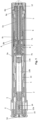
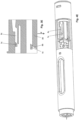
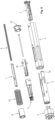
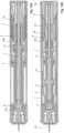
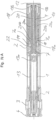
- the Figures 1 and 2 show a conceptual design of a first embodiment of an injection device according to the invention.
- the injection device comprises a sleeve-shaped housing 2, on which a syringe holder 1, a mechanism holder 5 and an end cap 12 are arranged fixedly to the housing, i.e. are immovable with respect to the housing 2.
- the syringe holder 1, the mechanism holder 5 and the end cap 12 can be latched, glued, welded, locked or snapped to the housing 2 or can be formed individually or entirely as one piece with the housing 2.
- a preferably pre-filled syringe 13 can be received in the syringe holder 1 and held thereby.
- the syringe 13 has a receiving space 13b delimited by a stopper 13a displaceable along the longitudinal axis of the syringe 13, in which a substance to be dispensed is contained, which substance can be released by displacing the stopper 13a in the distal longitudinal direction of the syringe 13 (in Fig. 1 to the left) from this space and can be dispensed in a known manner through a needle 14 arranged at the front of the syringe 13.
- the needle 14 is in the Fig. 1 In the initial state shown, the needle is surrounded by a needle protection cap 15, in which a needle protection element 15a, made of elastic or rubber, is present.
- the needle protection cap 15 can be removed together with the rubber element 15a contained therein by means of the cap removal element 4 placed thereon in order to expose the needle 14, which, in the initial position shown, is also surrounded by the front side of a needle protection sleeve 3 that can be pushed in and out again in the axial direction of the housing 2.
- An injection spring 9 serving as an energy storage or drive means is preloaded and held in the initial state between the piston rod 7 and the click pin 6.
- the injection spring 9 is mounted within the piston rod 7 and surrounded by the piston rod 7, pressing on or supporting itself against a distal base element 7b of the piston rod 7. In the proximal direction, the injection spring 9 is held by or supporting itself against a proximal base or plate element 6d of a click pin 6.
- the click pin 6 has an axially extending central web 6e, which, when inserted, is arranged within the injection spring 9 and is connected at the proximal end to the plate element 6d. From the plate element 6d, approximately parallel to the central web 6e, release snap arms 6a extend.
- release snap arms are deformable or resilient, so that the radially inwardly projecting inner cams 6b and radially outwardly projecting outer cams 6c arranged on each release snap arm 6a can be moved in the radial direction, i.e., radially outwards or inwards.
- the inner cams 6b engage in recesses or openings 7a in the piston rod 7, so that in this state, axial displacement between the click pin 6 and the piston rod 7 is not possible due to the force of the preloaded injection spring 9.
- the spring assembly consisting of the click pin 6, piston rod 7, and injection spring 9 cannot therefore be forced apart.
- a radial deflection of the trigger snap arms 6a to the outside is prevented by the axially displaceable locking sleeve 8 arranged in the area of the outer cams 6c around the click pin 6, the inside of which the outer cams 6c are opposite or in contact with.
- the injection spring 9 is preferably a compression spring or helical spring, which can preferably store or absorb at least the energy for a dispensing sequence and which is inserted into the injection device as a thus tensioned spring.
- the needle protection device 3 which is designed as a sleeve-shaped element and is mounted displaceably relative to the housing 2, has on its distal end face a passage opening 3d through which the needle 14 can pass or which can be moved back in the axial direction along the needle 14 or inserted into the housing 2. Extending in the axial direction are two opposite webs 3a are provided, which are located in the proximal direction relative to the passage opening 3d.
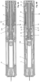
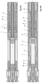
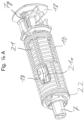
- FIGS. 3A and 3B are cross-sectional views of the injection device in the delivery state, offset by 90° relative to each other.
- the injection spring 9 is pre-tensioned between the piston rod 7 and the click pin 6.
- the piston rod 7 is held against the force of the injection spring 9, which exerts a force on the piston rod 7 in the distal direction, by the inner cams 6b of the trigger snap arms 6a of the click pin 6, as can be seen from Fig. 3B
- the locking sleeve 8 prevents a radially outward movement of the cams 6b and the trigger snap arms 6a.
- An end click element 11 is pushed or held in the proximal direction by a needle protection sleeve spring 10, which presses against an annular radial widening 11b of the click element 11.
- the needle protection sleeve spring 10 is supported on a flange 8g of the locking sleeve 8.
- the spring 10, like the spring 9, can be inserted into the injection device already pre-tensioned or relaxed.
- the locking sleeve 8 rests proximally offset against the webs 3a of the needle protection sleeve 3, which is held against displacement in the distal direction by radially outwardly projecting proximal cams 1a of the syringe holder 1, which engage in recesses or passages in the webs 3a.
- the click element 11 rests with its proximal end face on the plate-shaped base 12b of the end cap 12 which is snapped to the housing 2 by means of the snap fasteners 12a or is fixed to the housing.
- the syringe 13 inserted into the injection device is held forward in the syringe holder 1 by means of a shoulder support 1b or radially inwardly projecting projections 1b of the syringe holder 1 and secured in the housing 2 by means of a ring or a housing taper 2b.
- This ring or the housing taper 2b prevents radial deflection of the syringe holder 1b.
- the syringe holder 1 rests on its front side on radially inwardly projecting ribs or projections 2e of the housing 2.
- cams 1c on spring arms 1d of the syringe holder 1 fixed to the housing engage in an axially extending groove 3e of each web 3a of the needle protection sleeve 3 and are spaced apart from the above-mentioned radially projecting cam 1a in the axial direction by approximately the length of the axial groove 3e, so that the needle protection sleeve 3 is held against axial displacement by the axially spaced cams 1a and 1c engaging in the axial groove 3e, wherein the cams 1c provided on the spring arms 1d deflect radially inwards when a relatively small pressing force is applied to the needle protection sleeve 3 and enable the needle protection sleeve 3 to be pushed proximally into the housing.
- Fig. 3C - 3G show an internal development of 180°, i.e., one half, of the locking sleeve 8, with radially inwardly projecting areas shown hatched.
- the positions of the locking sleeve 8 are explained in conjunction with the movements of the needle guard 3.
- the locking sleeve is shown in the initial state of the needle guard.
- the guide areas or grooves of the locking sleeve 8 located between the hatched areas enable engagement of a radially outwardly directed cam 6c of the click pin 6.
- a cam 5c of the mechanism holder 5 which projects outward in the radial direction, engages with an axially extending groove 8a provided on the radial inside of the locking sleeve 8 and is engaged therewith, so that rotation of the locking sleeve 8 relative to the mechanism holder 5 fixed to the housing is prevented.
- the locking sleeve 8 can be displaced in the axial direction in the position shown.
- the needle 14 Before starting to use the injection device, the needle 14 must be exposed by pulling the cap removal element 4 in the distal direction from the distal front of the injection device. As shown in Fig. 3A As can be seen, the snap hooks 4a of the cap removal element 4 snap behind the rear edge of the needle protection cap 15. Ribs 2f of the housing 2 provided on the radially outer side of the snap hooks 4a prevent these snap hooks 4a from moving outwards, so that the needle protection cap 15 can be pulled off in the distal direction by pulling on the cap removal element 4. In the process, the elastic or rubber needle guard 15a fastened inside the needle protection cap 15 is also pulled off together with the needle protection cap 15, so that the needle 14 is exposed.
- the cap removal element 4 is held on the needle protection sleeve 3 by means of a snap element 4b, which engages behind a radially projecting snap holder 3b.
- a force must be applied which can overcome the snap holders 3b, 4b.
- the needle 14 After removal of the cap removal element 4 together with the needle protection cap 15, the needle 14 is exposed, but is still surrounded by the distal sleeve region of the needle protection sleeve 3, which also projects in the distal direction beyond the tip of the needle 14, so that the needle 14 is still protected by the front or distal part of the needle protection sleeve 3.
- the cap removal element is removed, 4 in the ready-to-use state, is pressed with its distal end face, i.e. the distal front area of the needle protection sleeve 3, onto a puncture site, the needle protection sleeve 3 is displaced in the proximal axial direction into the housing 2 by this pressure, which is usually applied to the housing 2 by a user holding the housing 2, whereby the needle 14, which is fixed relative to the housing 2, is exposed and inserted into the puncture site.
- the needle protection sleeve 3 By inserting the needle protection sleeve 3, the needle is Fig. 3B and 4B shown, the locking sleeve 8 resting on the proximal end of the webs 3a of the needle protection sleeve 3 is also displaced in the proximal direction relative to the housing 2, whereby the needle protection sleeve spring 10, which is supported between the mentioned contact surfaces of the locking sleeve 8 and the click element 11, is compressed or compressed.
- the radially outwardly projecting cam 6c located on an elastic release snap arm 6a of the click pin 6 is in the Fig. 3C shown starting position still outside a guide area on the radial inside of the locking sleeve 8 and is only moved after the puncture in the axial direction relative to the locking sleeve 8 by an axial displacement of the locking sleeve 8 relative to the housing 2 into an engagement area, as in Fig. 3D and in Fig. 4D shown, in which the cam 6c rests with a frontal bevel in the axial direction against a bevel 8b of the web 8h. Since in this state a distal direction (in Fig.
- the automatic injection is triggered.
- the locking sleeve 8 is displaced axially in the proximal direction by the adjacent webs 3a of the needle protection sleeve 3 within the housing 2 to such an extent that the trigger snaps 6a of the click pin 6 are released by the locking sleeve 8 no longer lying around the outer cams 6c and being displaced away, whereby the trigger snap arms 6a can deflect radially outwards.
- the corresponding radially outwardly pressed release snap arms 6a of the click pin 6 are in Fig. 5B shown.
- the click pin 6 is also released and pressed axially within the housing 2 in the proximal direction by the force of the injection spring 9 until the proximal end face of the pin 6 strikes the distal bottom surface of the end cap 12, as shown in the Figures 5A and 5B shown.
- the impact of the click pin 6 on the end cap 12 generates a start signal or start click.
- Damping elements can be mounted between the end cap 12 and the click pin 6, whereby the impact of the click pin 6 can be delayed or slowed down, thus modifying the start signal.
- a compression rib 12c and a counter rib 12c' which is at an angle to the compression rib 12c, may be attached.
- additional damping tabs or snaps 12d and opposing damping ribs 12d' may be attached.
- the needle protection lock is activated by pressing the release arms 6a (Fig. 4D)
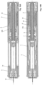
- FIGS. 5A and 5B show cross-sectional views of the injection device offset by 90° to each other after the start click, which signals the start of the injection acoustically and tactilely, and the activation of the signal described below to indicate the end of the injection (End-Of-Injection Click).
- the piston rod 7 is moved in the distal direction by the force of the relaxing injection spring 9 and comes into contact with the plug 13a, on which the piston rod 7 exerts a force acting in the distal direction by the proximally supported injection spring 9, whereby the plug 13a is pushed into the syringe 13 in order to displace the substance contained in the syringe 13, which is delivered or injected through the inserted needle 14.
- the piston rod 7 is, as in Fig. 4A shown, before being moved to meet the proximal side of the plug 13a, it is still connected to the click element 11 by means of the cams 11a, which engage in corresponding depressions or recesses of the piston rod 7. This engagement is secured by the mechanism holder 5 surrounding the click element arms 11c, which prevents the click element arms 11c from deflecting radially outwards and thus from disengaging from the piston rod 7. If the piston rod 7 has been displaced far enough in the distal direction that outer cams 11d of the click element arms 11c can engage in deflection openings of the mechanism holder 5, as in Fig.
- the click element arms 11c are forced out of engagement with the piston rod 7 and expand, so that the displacement-proof coupling with the piston rod 7 is released. This holds the click element 11 backwards. Since the locking sleeve spring 10 is supported at its proximal end against the click element 11, the locking sleeve spring 10 is tensioned by the displacement of the click element 11 in the distal direction, as can be seen from the Figures 5A and 5B This results in an energy transfer from the relaxing injection spring 9 to the tensioning locking sleeve spring 10.
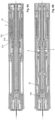
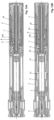
- FIGS. 6A and 6B show longitudinal cross-sectional views of the injection device, offset by 90° to each other, after the substance has been dispensed.
- the piston rod 7, which prevents a radially inward movement of the cams 11a on the click element arms 11c, which is fixed to the inner cam 11c of the click element 11 in the Figures 5A and 5B shown condition is after the pouring, as in Fig. 6A shown, have been displaced in the distal direction until the click element arms 11c are released again. Since the click element 11 is pressurized in the proximal direction by the needle protection sleeve spring 10, the holding engagement of the click element arms 11c is released by means of the outer cams 11d in the mechanism holder 5 and releases the click element 11, as shown in Fig. 7A shown.
- the click element 11 After being released by the needle shield spring 10, the click element 11 is moved in the proximal direction until it strikes the base 12b of the end cap 12, causing a final click.
- This final click is audible and can also be perceived tactilely by a user, thus signaling the end of the injection. The final click is therefore not caused by the injection spring 9.
- FIGS. 7A and 7B show longitudinal cross-sectional views of the injection device offset by 90° from each other during or after the final click. If the injection device is removed from the injection site after dispensing, the needle protection sleeve 3, together with the locking sleeve 8 pressing against it, both of which are subjected to a force in the distal direction by the needle protection sleeve spring 10, moves forward, i.e., axially in the distal direction relative to the housing 2.
- the force of the needle protection sleeve spring 10 moves the locking sleeve 8 in the distal direction (in Fig. 3E to the left and Fig. 4E ) axially, whereby this axial displacement triggers a rotation of the locking sleeve 8 by means of the bevels 8b and the cam 6c, thereby guiding the cam 5c into engagement with the axially extending groove 8c and thus preventing the locking sleeve 8 from rotating during this displacement. If the locking sleeve 8 has been displaced so far that the cam 5c comes into contact with the bevel 8i at the proximal end of the groove 8c, as shown in the Fig.
- a centering cam 3c provided on a respective web 3a of the needle protection sleeve 3 engages in a centering groove 8e of the locking sleeve 8 and thus prevents the locking sleeve 8 from being turned back.
- the needle protection sleeve 3 is pushed out beyond the needle 14 and secured against being pushed back by the cam 5c located at the step 8f of the locking track 8c.
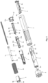
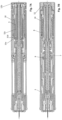
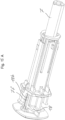
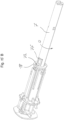
- Figure 8 shows an exploded view of a second embodiment of an injection device.
- the Figures 9A and 9B show longitudinal cross-sectional views offset by 90° from each other in the as-delivered state.
- the injection spring 9 is preloaded between the piston rod 7 and the end cap 12.
- a release sleeve 16 rests forwardly on the mechanism holder 5 via ribs 16c.
- the mechanism holder 5 and the end cap 12 are firmly connected to one another.
- the piston rod 7 is held in the distal direction by a release snap 16a of the release sleeve 16 and secured by means of the locking sleeve 8.
- a cam 5c of the mechanism holder 5 engages with an axially extending groove 8a of the locking sleeve 8 and prevents the locking sleeve 8 from rotating relative to the mechanism holder 5.
- the needle protection sleeve spring 10 is preloaded between the locking sleeve 8 and the release sleeve 16.
- the mechanism holder 5 and the end cap 12 are fixed to the housing and connected to the housing 2, for example, by snapping or locking.
- the locking sleeve 8 rests on webs or tabs 3a of the needle protection sleeve 3, which is held at the front by a cam 1a on the syringe holder 1.
- the release sleeve 16 is held at the rear by the release arms 16a of the release sleeve 16 secured by the locking sleeve 8 on the piston rod 7.
- the syringe 13 is secured as described in the first embodiment by means of a shoulder support 1b and by means of a ring or a housing taper 2b.
- the needle protection cap 4 is also removed as described in the first embodiment.
- Figures 10A and 10B Show longitudinal cross-sectional views of the injection device, rotated by 90° to each other, in the inserted state when the injection device is pressed onto the injection site.
- the needle protection sleeve 3 is pressed into the housing 2 up to the stop 2c while the needle 14 is inserted into the injection site.
- the needle protection sleeve 3 displaces the locking sleeve 8 relative to the mechanism holder 5 and the release sleeve 16, thereby compressing or compressing the needle protection sleeve spring 10.
- the injection is triggered by completely inserting the needle protection sleeve 3 into the housing 2.
- the locking sleeve 8 is thereby moved relative to the housing 2, the mechanism holder 5 and the release sleeve 16 in the proximal direction (in Fig. 10 to the right), releasing the release catches 16a.
- the force of the injection spring 9 pushes the release catches 16a open and releases them in a forward-distal direction against the movement of the piston rod 7.
- the release sleeve 16 is now held rearward by the catches 16b on the mechanism holder 5.
- FIGS 11A and 11B show longitudinal cross-sectional views of the injection device, offset by 90° to one another, after dispensing and after the click to signal the end of the injection (end-of-injection click).
- the piston rod 7 has been moved in the distal direction by the force of the injection spring 9, whereby the piston rod 7 presses on the stopper 13a and moves it in the distal direction until it rests against the end of the glass body of the syringe 13.
- the piston rod 7 has a slot 7b at its proximal end, whereby the arms 16b of the release sleeve 16 are released at the end of the injection and the locking of the release sleeve 16 to the rear is removed.
- the needle guard locking is effected in the same way as described in the first embodiment, wherein the deflected trigger arms are arranged on the release sleeve 16 and not on the click pin 6, so that reference is made to the above description in this regard.
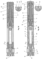
- the Figures 12A and 12B show longitudinal cross-sectional views, offset by 90° from one another, of a third embodiment of an injection device in the delivery state.
- the injection spring 9 is preloaded between the piston rod 7 and the release sleeve 16.
- the release sleeve 16 is held by the arms 16b on the mechanism holder 5 and secured by means of the piston rod 7.
- the piston rod 7 is held forward by the release catches 16a and secured by means of the locking sleeve 8.
- the cam 5c of the mechanism holder 5 engages with the axially extending groove 8a of the locking sleeve 8 and prevents rotation of the locking sleeve 8 relative to the mechanism holder 5 fixed to the housing.
- the needle guard spring 10 is preloaded between the locking sleeve 8 and the mechanism holder 5.
- the mechanism holder 5 is snapped onto the housing 2.
- the locking sleeve 8 rests on the tabs 3a of the needle guard 3, which is held forward by the cam 1a on the syringe holder 1.
- the syringe 13 is stored in the syringe holder 1 and housing 2 as described in the above embodiments.
- the removal of the cap removal element 4 to remove the needle protection cap 15 is carried out as described above.
- FIGS. 13A and 13B show longitudinal cross-sectional views, offset by 90° to each other, of the injection device which has been pressed onto the injection site, the contents of the syringe have been dispensed and the end of the injection has been signaled.
- the needle 14 is inserted.
- the needle protection sleeve 3 is pressed into the housing 2 up to the stop 2c.
- the needle protection sleeve 3 displaces the locking sleeve 8 relative to the mechanism holder 5 and the release sleeve 16, compressing the needle protection sleeve spring 10.
- the injection is triggered by fully inserting the needle protection sleeve 3 into the housing 2.
- the locking sleeve 8 is displaced proximal to the housing 2, the mechanism holder 5, and the release sleeve 16, thereby releasing the trigger snaps 16a.
- the force of the injection spring 9 pushes the trigger snaps 16a open and releases them against the forward movement of the piston rod 7.
- the piston rod 7 Due to the force of the injection spring 9, the piston rod 7 has been moved in the distal direction, whereby the piston rod 7 presses on the stopper 13a and moves it in the distal direction until it rests against the end of the glass body of the syringe 13.
- the piston rod 7 has a slot 7e at its proximal end, whereby the arms 16b of the release sleeve 16 are released at the end of the injection and the locking of the release sleeve 16 in the proximal direction or to the rear is canceled.
- the needle guard locking is carried out in the same way as described in the second embodiment.
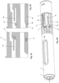
- Fig. 14A shows a longitudinal cross-sectional view of another embodiment of an injection device in the delivery state, in which the injection spring 9 rests at its distal end on the inside of the piston rod 7. At its proximal end, the injection spring 9 rests on a housing-fixed holding sleeve 18, which surrounds a click pin 20 and engages radially at a proximal point with engagement arms 18c through openings in the piston rod 7.
- the click pin 20, which is provided for generating the final click is moved in the proximal direction (in Fig. 14A to the right) against the holding sleeve 18, whereby the end cap 12 can be a part of the holding sleeve 18.
- the syringe spring 19 is supported in the proximal direction on the arms 20a of the click pin 20 and presses in the distal direction on the syringe 13 in order to store the syringe securely in the syringe holder 1 by the pressure thus generated in the distal direction.
- the arms 20a of the click pin 20 are engaged in openings 7a of the piston rod 7 by means of radially inwardly projecting cams 20b and can be taken along during a distally directed movement of the piston rod 7, so that the piston rod 7, during a distal movement, moves out of the Fig. 14A
- the click pin 20 is initially taken along. A release of the retaining connection 7a, 20b due to radial deflection of the arms 20a is prevented by the retaining sleeve 18 surrounding the click pin 20.
- a release sleeve 22 is displaced axially in the proximal direction by the adjacent webs 3a of the needle protection sleeve 3 against the force of the needle protection sleeve spring 10 within the housing 2 to such an extent that a holding element of the holding sleeve 18, which engages in the piston rod 7, is released.
- the now released piston rod 7 can be moved in the distal direction towards the plug 13a of the syringe 13 and push this plug 13a into the syringe 13 in order to carry out the dispensing.
- the click pin 20 is carried along by the piston rod 7 until the arms 20a of the click pin can deflect radially in the release 18a of the holding sleeve 18 and, through this engagement, the cams 20c located radially on the outside of the arms 20a are held on the holding sleeve 18.
- a radially inward deflection of the arms 20a of the click pin 20 is impossible due to the piston rod 7 resting on the inside of the cams 20b until the piston rod 7 has been moved far enough in the distal direction for complete dispensing to take place.
- the arms 20a of the click pin 20 can deflect radially inwards, since the piston rod 7 has been moved so far in the distal direction that either according to an embodiment not shown the piston rod has already been moved completely past the cams 20b or, as in Fig. 14B shown, the internal cams 20b can be directed back into openings or clearances on the piston rod 7.
- the click pin 20 is thus no longer held by cams 20c or 20b and is accelerated in the proximal direction by the pre-tensioned syringe spring 19 in order to strike the holding sleeve 18 or alternatively the end cap 12 (not shown) and thus generate an end click sound.
- Fig. 15A shows another embodiment of a functional unit for generating an end click.
- An injection spring is preloaded torsionally between the piston rod 7 and a stabilizing pin or the retaining sleeve 18.
- the stabilizing pin rests on the bottom of the retaining sleeve 18 and extends axially within the injection spring and is secured against twisting by the retaining sleeve 18.
- the piston rod 7 is linearly guided in a linear guide 18b by means of a linear guide element 7f in the holding sleeve 18.
- the piston rod 7 can also rotate on the stopper 13a of the syringe 13.
- Fig. 16A shows a further embodiment of a functional unit for generating a final click, wherein the energy for the final click is provided by the needle protection sleeve spring 10.
- the needle protection sleeve spring 10 is arranged between the Fig. 16A
- the release sleeve 22 and the click sleeve 21 are pre-tensioned.
- the click sleeve 21 has hooks 21a which engage with the retaining sleeve 18.
- the piston rod 7 has a cam 7g which towards the end of the injection, as in Fig. 16B shown by passing from proximal to distal (in Fig. 16B from right to left) the hooks 21a of the Click sleeve 21 is pressed open, whereby it is released from the holding sleeve 18 and the coupling of the click sleeve 21 with the holding sleeve 18 is released.
- the click sleeve 21 is accelerated or moved backward or in the proximal direction by the needle protection sleeve spring 10 to a stop on the holding sleeve 18, whereby the final click is generated.
Landscapes
- Health & Medical Sciences (AREA)
- Vascular Medicine (AREA)
- Engineering & Computer Science (AREA)
- Anesthesiology (AREA)
- Biomedical Technology (AREA)
- Heart & Thoracic Surgery (AREA)
- Hematology (AREA)
- Life Sciences & Earth Sciences (AREA)
- Animal Behavior & Ethology (AREA)
- General Health & Medical Sciences (AREA)
- Public Health (AREA)
- Veterinary Medicine (AREA)
- Infusion, Injection, And Reservoir Apparatuses (AREA)
Description
- Die Erfindung betrifft eine Substanzabgabevorrichtung, insbesondere eine Injektionsvorrichtung oder einen Autoinjektor, die eine Signalisierungsvorrichtung aufweist, um z. B. akustisch und/oder taktil anzuzeigen, wann eine Abgabe einer Substanz oder eine Ausschüttung vollständig oder mindestens zu einem vorgegebenen Teil erfolgt ist. Eine z.B. automatisch ausschüttbare Substanz kann ein fluides Produkt oder Medikament sein, welches z.B. flüssig, pastenartig oder gelartig ist.
- Aus der
WO 2011/123024 A1 ist eine Medikamentenabgabevorrichtung mit einer auf einen Medikamentenbehälter wirkenden Antriebseinrichtung zum Ausstoßen eines Medikaments bekannt, wobei eine Halteeinrichtung konfiguriert ist, um die Antriebseinrichtung in einem vorgespannten Zustand zu halten. Eine Aktivierungseinrichtung wirkt mit der Halteeinrichtung zum Lösen der Antriebseinrichtung aus dem vorgespannten Zustand zusammen. Eine Rückmeldeeinrichtung kann sowohl mit der Halteeinrichtung als auch mit der Antriebseinrichtung zusammenwirken, um ein Signal zu erzeugen, das anzeigt, dass das Medikament vollständig ausgestoßen wurde. - Die
WO 94/11041 - Die
WO 2013/016832 A1 offenbart eine Injektionsvorrichtung zum automatischen Ausschütten mit einer Nadelschutzeinrichtung, die von einer distalen in eine proximale Position und von dieser in eine Nadelschutzposition verschiebbar ist und mit einer im Gehäuse bewegbaren Antriebseinrichtung, welche durch ein Antriebsmittel in eine Ausschüttposition getrieben wird und mit einer Drehhülse, die von einer ersten in eine zweite Position drehbar ist. - In der
US20100127798 ist ein Autoinjektor beschrieben, bei dem nach der Injektion des Medikaments der Spritzenhalter (10) mit der integrierten Spritze (2) nach der Injektion zurückgezogen wird. Der sogenannte Spritzenrückzug geschieht mittels der Rückzugsfeder (7). Wobei nach der Injektion des Medikaments und kurz vor dem Spritzenrückzug ein Signal erzeugt wird. Hierfür verschiebt die Rückzugsfeder (7) für die Signalerzeugung den Spritzenhalter (10) nach proximal um den proximalen Bereich (switch cam 17) vom Spritzenhalter (10) gegen eine Fensteröffnung (20) anzuschlagen und so ein Signal zu generieren. Nach dem Signal wird der Spritzenhalter (10) von der Rückzugsfeder (7) vollständig zurückgezogen, damit die Nadel (4) aus der Injektionsstelle herausgezogen wird. -
WO2013/016832 A1 weist ein erstes Profil auf, welches in Wirkverbindung mit einem zweiten Profil der Antriebseinrichtung steht. Das Antriebsmittel dreht durch das erste Profil und das zweite Profil die Drehhülse von der ersten in die zweite Position.US 20100137798 offenbart einen Autoinjektor, bei dem nach der Injektion des Medikaments ein Spritzenhalter mit der integrierten Spritze zurückgezogen wird. Der sogenannte Spritzenrückzug geschieht mittels der Rückzugsfeder, wobei nach der Injektion des Medikaments und kurz vor dem Spritzenrückzug ein Signal erzeugt wird. Hierfür verschiebt die Rückzugsfeder den Spritzenhalter nach proximal gegen eine Fensteröffnung einer Betätigungshülse. Nach dem Signal wird der Spritzenhalter von der Rückzugsfeder vollständig zurückgezogen und die Nadel aus der Injektionsstelle herausgezogen. - Es ist eine Aufgabe der Erfindung eine Substanzabgabevorrichtung oder Injektionsvorrichtung bereitzustellen, bei welcher der Anwender auf einfache Art eine Injektion auslösen und durch die Vorrichtung über den korrekten Funktionsablauf informiert werden kann. Diese Aufgabe wird gelöst durch eine Vorrichtung mit den Merkmalen des unabhängigen Anspruchs.
- Eine erfindungsgemäße Vorrichtung zum Verabreichen einer Substanz ist in Anspruch 1 definiert und umfasst eine Injektionsfeder, mit welcher die Ausschüttung automatisch durchgeführt werden kann. Dabei ist keine extern z.B. von einem Benutzer zuzuführende oder aufzuwendende Kraft oder Energie erforderlich. Die Injektionsfeder speichert vorteilhaft die vollständige für eine automatische Substanzabgabe erforderliche Energie. Diese Feder kann in einem energiespeichemden Zustand, also z.B. komprimiert, auseinandergezogen oder auch verdreht, in die Injektionsvorrichtung eingebaut werden und durch einen Energieabgabevorgang, also z. B. durch Entspannen, wenn die Feder komprimiert oder verdreht bzw. auf Torsion beansprucht eingebaut wurde, oder auch durch Zusammenziehen, wenn die Feder auseinandergezogen eingebaut wurde, Energie abgeben. Die Energieabgabe erfolgt vorteilhaft unmittelbar oder mittelbar, d. h. über zwischengeschaltete Bauelemente, an eine Kolbenstange oder ein Druckelement, welches auf einen Stopfen einer Spritze drückt und diesen Stopfen in die Spritze einschieben kann.
- Optional kann das Energiespeicherelement oder ein weiteres separates Energiespeicherelement vorgesehen sein, um auch den Vorgang des Einstechens einer Nadel zu automatisieren. Der Einstechvorgang kann jedoch auch manuell erfolgen, also z. B. durch einen Benutzer vorgenommen werden, ohne hierfür in der Injektionsvorrichtung gespeicherte Energie zu verwenden.
- Die Verabreichungsvorrichtung weist eine Nadel als Abgabeelement auf, durch welches die Substanz abgegeben werden kann. Die Nadel ist auf bekannte Art mit dem Behältnis für die abzugebende Substanz gekoppelt, sodass z. B. beim Verschieben des oben erwähnten Stopfens die Substanz durch die Nadel hindurchtritt und am distalen vorderen Ende der Substanz abgegeben und injiziert wird.
- Für das Abgabeelement ist ein Schutzelement vorgesehen, beispielsweise eine über das Abgabeelement hinauszuschiebende Hülse, welche beispielsweise parallel zur Längsrichtung einer als Abgabeelement dienenden Nadel axial verschoben werden kann. Das Schutzelement kann vor der Abgabe das Abgabeelement z. B. radial umgeben und auch distal über das Abgabeelement hinausragen, so dass das Abgabeelement im Wesentlichen oder vollständig durch das Schutzelement umgeben oder bedeckt wird. Dabei weist das Schutzelement vorteilhaft eine Durchtrittsöffnung für das Abgabeelement auf, durch welche das Abgabeelement den Schutzbereich des Schutzelements verlassen kann. Es kann sowohl das Abgabeelement aktiv durch das Schutzelement hindurchbewegt werden als auch das Schutzelement aktiv von dem Abgabeelement entfernt, also z. B. in proximale Richtung zurückgeschoben, werden, um zumindest den distalen Bereich des Abgabeelements freizugeben.
- Das Schutzelement ist mit einem Antriebselement gekoppelt, welches separat von den oben erwähnten optional vorgesehenen Antriebselementen ausgebildet ist, z. B. als eine zweite oder dritte Antriebsfeder innerhalb einer Injektionsvorrichtung. Mit diesem Antriebselement kann das Schutzelement angetrieben werden. Z. B. kann das Antriebselement bewirken, dass das Schutzelement nach erfolgter Substanzabgabe wieder über das Abgabeelement gebracht oder geschoben werden kann. Optional kann das Antriebselement auch als Halteelement dienen, z. B. um das Schutzelement vor und/oder nach einer Substanzabgabe in einer Schutzstellung über oder um das Abgabeelement zu halten. Das Antriebselement kann in einem entspannten Zustand oder in einem gespannten oder geladenen, also Energie beinhaltenden oder speichernden, Zustand in der Injektionsvorrichtung eingebaut sein, wobei diese Energie zum Antreiben des Schutzelements dienen kann. Wird das Antriebselement in einem Zustand in der Injektionsvorrichtung eingebaut, in welchem dieses keine oder wenig Energie speichert, so muss das Antriebselement während eines Funktionsablaufes vor dem Antreiben des Schutzelements von einem anderen Element mit Energie versorgt werden, also von einem der erwähnten weiteren Antriebselemente, z.B. einer gespannten Ausschüttfeder.
- Eine Rückkopplungsvorrichtung der Injektionsvorrichtung erzeugt ein Signal, wenn eine vorgegebene oder die gesamte Menge der abzugebenden Substanz abgegeben wurde. Das erzeugte Signal kann ein akustisches Signal sein, also z. B. ein "Klick"-Geräusch, welches erzeugt wird, wenn ein sich bewegendes Element an einem anderen anschlägt. Das Signal kann auch ein taktiles oder haptisches Signal sein, also ein Signal, welches von einem Benutzer erfühlt werden kann. Ein solches Signal kann z. B. ebenfalls durch einen Anschlag eines Elements an einem anderen Element erzeugt werden.
- Erfindungsgemäß ist die Rückkopplungsvorrichtung mit dem Antriebselement gekoppelt, mit welchem auch das Schutzelement gekoppelt ist. Das Rückkopplungsvorrichtung ist ein Anschlagelement, also ein Pin oder eine Hülse, welche von einer Nadelschutzhülsenfeder beschleunigt oder gegen einen Anschlag bewegt wird, wobei die Nadelschutzhülsenfeder ein Nadelschutzelement mit Druck beaufschlagt oder Kraft auf dieses ausübt, um das Nadelschutzelement relativ zur Nadel in eine Schutzposition zu bringen oder zu halten.
- Das Rückkopplungselement kann z. B. an dem Gehäuse der Injektionsvorrichtung anschlagen, ist also relativ zu diesem bewegbar, wobei es auch möglich ist, dass das Rückkopplungselement an jedem anderen Teil anschlägt. Vorzugsweise wird das Rückkopplungselement von dem erwähnten Antriebselement über eine vorgegebene Strecke z. B. geradlinig oder in einer Drehbewegung beschleunigt, um mit einer bestimmten Geschwindigkeit einen Aufschlag und somit ein bemerkbares Rückkopplungssignal zu erzeugen.
- Die erfindungsgemäße Vorrichtung kann eine weitere separate zweite Rückkopplungsvorrichtung aufweisen, welche z. B. den Beginn der Substanzabgabe signalisiert. Es ist denkbar, dass beide Rückkopplungsvorrichtungen auch in einem Element realisiert werden können.
- Wie bereits erwähnt, weist die Verabreichungsvorrichtung auch ein weiteres Antriebselement oder Energiespeicherelement auf, welches Energie zur Bewirkung der Substanzabgabe und/oder Energie zur Durchführung eines Nadeleinstichs zur Verfügung stellt. Dieses weitere Antriebselement ist separat von dem Antriebselement vorgesehen, welches mit der Rückkopplungsvorrichtung gekoppelt ist und kann z. B. funktional vollständig von dem Rückkopplungs-Antriebselement getrennt sein. Ebenso ist es möglich, dass ein solches weiteres Antriebselement Energie an das Rückkopplungs-Antriebselement abgibt oder überträgt.
- An dem Rückkopplungselement kann auch ein Modulations- oder Dämpfungselement vorgesehen sein, mittels welchem die Rückkopplung, also z. B. ein Rücckopplungsgeräusch oder ein taktiles Rückkopplungssignal, beeinflusst oder modifiziert werden kann. Beispielsweise können Laschen oder Anschlagflächen oder Dämpfungsmittel vorgesehen sein, welche einen Aufprall oder Aufschlag der Rückkopplungsvorrichtung auf einer Fläche oder einem Aufschlagsteil verzögern oder abbremsen. Ebenso ist es möglich, dass ein Modulationselement die Anschlagsfläche vergrößert, um die zu erzeugende Signalstärke zu vergrößern.
- Das Rückkopplungselement kann vorzugsweise von einer lösbaren Haltevorrichtung bis zum Ende der Substanzabgabe gehalten werden, sodass beispielsweise das Rückkopplungselement erst dann freigegeben oder ausgelöst und z. B. erst dann von einem Antriebselement angetrieben wird, wenn die Substanzabgabe vollständig oder bis zu einem gewissen vorher definierten Grad erfolgt ist, also z. B. die Kolbenstange bis zu einem festgelegten Ausschüttpunkt verschoben wurde.
- Die Rückkopplungsvorrichtung ist ein Anschlagselement, welches entlang einer geraden Strecke beschleunigt oder angetrieben wird, um am Ende an einem Anschlagsort aufzutreffen und so ein Rückkopplungssignal zu erzeugen. Ebenso ist es möglich, dass die Rückkopplungsvorrichtung beispielsweise ein Drehelement ist, welches z. B. nach der festgestellten Beendigung der vollständigen Substanzabgabe eine Drehbewegung ausführt und einen Drehanschlag erzeugt. Hierfür kann z. B. ein Torsionsmoment einer verwendeten Feder, also z. B. einer verwendeten Nadelschutzfeder oder auch einer Injektionsfeder, verwendet werden.
- Gemäß einem weiteren Aspekt bezieht sich die Erfindung auf ein Verfahren zum Abgeben einer Substanz aus einer wie oben beschriebenen Vorrichtung, wobei die Substanz mittels eines ersten Antriebselements automatisch abgegeben wird und ein Rückkopplungssignal zur Signalisierung der z. B. beendeten Substanzabgabe mittels eines von einem separaten zweiten Antriebselements angetriebenen Rückkopplungselements erzeugt wird. Die Antriebselemente sind folglich separate Vorrichtungen oder Funktionseinheiten, also beispielsweise zwei getrennt vorgesehene Federn, welche jedoch miteinander gekoppelt werden können, um Energie von einer Feder, also z. B. von einer Antriebsfeder, auf eine andere Feder, also z. B. die Rückkopplungsfeder, zu übertragen.
- Diese Energie- oder Kraftübertragung erfolgt während der Substanzabgabe.
- Die Erfindung wird nur anhand der ersten Ausführungsform beschrieben. Es zeigen:
- Fig. 1
- eine Querschnittsansicht entlang einer Längsachse einer ersten Ausführungsform einer Injektionsvorrichtung zur Veranschaulichung des Konzeptaufbaus;
- Fig. 2
- eine Explosionsansicht der in
Fig. 1 gezeigten Injektionsvorrichtung; - Fig. 3A und 3B
- um 90° zueinander gedrehte Querschnittsansichten der Injektionsvorrichtung im Auslieferungszustand;
- Fig. 3C bis 3G
- Abwicklung der radialen Innenseite der Verriegelungshülse (180° Abwicklung) zur Veranschaulichung der Relativbewegung der eingreifenden Nocken des Mechanikhalters und des Klick Pins
- Fig. 4A und 4B
- um 90° gedrehte Querschnittsansichten der Injektionsvorrichtung im eingestochenen Zustand, wenn die Injektionsvorrichtung auf die Injektionsstelle gedrückt wird oder wurde;
- Fig. 4D bis 4H
- Detailansicht der Verriegelungshülse und das Prinzip der Nadelschutzverriegelung zur Veranschaulichung der Relativbewegung der eingreifenden Nocken des Mechanikhalters und des Klick Pins
- Fig. 5A und 5B
- um 90° zueinander gedrehte Querschnittsansichten der Injektionsvorrichtung vor dem Beginn der Ausschüttung;
- Fig. 6A und 6B
- um 90° zueinander versetzte Querschnittsansichten der Injektionsvorrichtung nach erfolgter Ausschüttung;
- Fig. 7A und 7B
- um 90° zueinander versetzte Querschnittsansichten der Injektionsvorrichtung nach erfolgter Ausschüttung und diese erfolgte Ausschüttung bestätigenden Anschlag eines Klick-Elements;
- Fig. 8
- eine Explosionsansicht einer zweiten Ausführungsform einer Injektionsvorrichtung
- Fig. 9A und 9B
- um 90° zueinander gedrehte Querschnittsansichten der Injektionsvorrichtung im Auslieferungszustand;
- Fig. 10A und 10B
- um 90° zueinander versetzte Längsquerschnittsansichten der Injektionsvorrichtung im eingestochenen Zustand, wenn die Injektionsvorrichtung auf die Injektionsstelle gedrückt wurde;
- Fig. 11A und 11B
- um 90° zueinander versetzte Querschnittsansichten der Injektionsvorrichtung nach erfolgter Ausschüttung und erfolger Signalisierung des Endes der Injektion durch Anschlag der Freigabehülse an der Endkappe;
- Fig. 12A und 12B
- eine um 90° zueinander gedrehte Querschnittsansichten einer dritten Ausführungsform einer Injektionsvorrichtung im Auslieferungszustand;
- Fig. 13A und 13B
- um 90° zueinander versetzte Querschnittsansichten der Injektionsvorrichtung nach erfolgter Einstech- und Ausschüttbewegung und Bestätigung der vollständigen Ausschüttung durch Anschlag der Freigabehülse am Boden des Mechanikhalters.
- Fig. 14A
- zeigt eine weitere Ausführungsform einer Injektionsvorrichtung im Auslieferungszustand, bei welcher die Spritzenfeder die Energie für den Endklick (End-of-Injection-Klick) zur Verfügung stellt;
- Fig. 14B
- zeigt die Injektionsvorrichtung gemäß
Fig. 14A im ausgeschütteten Zustand vor dem Endklick; - Fig. 15A
- zeigt eine weitere Ausführungsform einer End-Klick-Einheit im Auslieferungszustand, bei welcher ein rotativer Anschlag durch ein Torsionsmoment der Injektionsfeder erzeugt wird;
- Fig. 15B
- zeigt die Funktionseinheit von
Fig. 15A bei erzeugtem Endklick; - Fig. 16A
- zeigt eine weitere Ausführungsform einer Funktionseinheit im Auslieferungszustand zur Erzeugung eines Endklicks durch die Energie der Nadelschutzhülsenfeder;
- Fig. 16B
- zeigt die Funktionseinheit von
Fig. 16A nach erfolgtem Endklick. - Die
Figuren 1 und2 zeigen einen Konzeptaufbau einer ersten Ausführungsform einer erfindungsgemäßen Injektionsvorrichtung. Die Injektionsvorrichtung umfasst ein hülsenförmiges Gehäuse 2, an welchem ein Spritzenhalter 1, ein Mechanikhalter 5 und eine Endkappe 12 gehäusefest angeordnet, also bezüglich des Gehäuses 2 unbeweglich sind. Der Spritzenhalter 1, der Mechanikhalter 5 und die Endkappe 12 können mit dem Gehäuse 2 verrastet, verklebt, verschweist, verriegelt oder verschnappt oder auch jeweils oder insgesamt einteilig mit dem Gehäuse 2 ausgebildet sein. In dem Spritzenhalter 1 kann eine vorzugsweise bereits vorgefüllte Spritze 13 aufgenommen und von diesem gehalten werden. Die Spritze 13 weist einen durch einen entlang der Längsachse der Spritze 13 verschiebbaren Stopfen 13a begrenzten Aufnahmeraum 13b auf, in welchem eine abzugebende Substanz enthalten ist, welche durch Verschiebung des Stopfens 13a in distale Längsrichtung der Spritze 13 (inFig. 1 nach links) aus diesem Raum heraus verdrängt und durch eine an der Vorderseite der Spritze 13 angeordnete Nadel 14 auf bekannte Art abgegeben werden kann. Die Nadel 14 ist imFig. 1 gezeigten Ausgangszustand von einer Nadelschutzkappe 15 umgeben, in welcher ein z. B. elastisches oder aus Gummi gefertigtes Nadelschutzelement 15a vorhanden ist. Die Nadelschutzkappe 15 kann zusammen mit dem darin enthaltenen Gummielement 15a mittels des darauf aufgesetzten Kappenabzugselements 4 abgezogen werden, um die Nadel 14 freizulegen, welche in der gezeigten Ausgangslage auch von der Vorderseite einer in axialer Richtung des Gehäuses 2 einschiebbaren und wieder ausfahrbarer Nadelschutzhülse 3 umgeben wird. - Eine als Energiespeicher oder Antriebsmittel dienende Injektionsfeder 9 ist vorgespannt und wird im Ausgangszustand zwischen der Kolbenstange 7 und dem Klick-Pin 6 gehalten, wobei die Injektionsfeder 9 innerhalb der Kolbenstange 7 gelagert ist und von der Kolbenstange 7 umgeben wird und auf ein distales Bodenelement 7b der Kolbenstange 7 drückt bzw. sich gegen dieses abstützt. In proximaler Richtung wird die Injektionsfeder 9 von einem proximalen Boden- oder Tellerelement 6d eines Klick-Pins 6 gehalten bzw. stützt sich gegen dieses ab. Der Klick-Pin 6 weist einen in axialer Richtung verlaufenden Mittelsteg 6e auf, welcher im eingesetzten Zustand innerhalb der Injektionsfeder 9 angeordnet ist und am proximalen Ende mit dem Tellerelement 6d verbunden ist, von welchem sich in etwa parallel verlaufend zum Mittelsteg 6e Auslöseschnapparme 6a erstrecken, welche verformbar oder federnd ausgebildet sind, so dass die an jedem Auslöseschnapparm 6a angeordneten radial nach innen vorstehenden Innennocken 6b und radial nach außen vorstehenden Außennocken 6c in radialer Richtung, also radial nach außen oder innen bewegt werden können. Die Innennocken 6b greifen in Vertiefungen oder Öffnungen 7a der Kolbenstange 7 ein, so dass in diesem Zustand eine axiale Verschiebung zwischen Klick-Pin 6 und Kolbenstange 7 durch die Kraft der vorgespannten Injektionsfeder 9 nicht möglich ist. Das aus Klick-Pin 6, Kolbenstange 7 und Injektionsfeder 9 bestehende Federpaket kann somit nicht auseinander gedrückt werden. Ein radiales Ausweichen der Auslöseschnapparme 6a nach außen wird durch die im Bereich der Außennocken 6c um den Klick-Pin 6 herum angeordneten axial verschiebbare Verriegelungshülse 8 verhindert, deren Innenseite die Außennocken 6c gegenüberliegen oder an dieser anliegen.
- Die Injektionsfeder 9 ist vorzugsweise eine Druckfeder oder Wendelfeder, welche bevorzugt mindestens die Energie für eine Ausschüttsequenz speichert oder aufnehmen kann und welche als so gespannte Feder in die Injektionsvorrichtung eingesetzt wird.
- Die Nadelschutzeinrichtung 3, welche als hülsenförmiges Element ausgebildet ist und relativ zum Gehäuse 2 verschiebbar gelagert ist, weist an ihrer distalen Stirnseite eine Durchtrittsöffnung 3d auf, durch welche die Nadel 14 hindurchtreten bzw. welche in axialer Richtung entlang der Nadel 14 zurück bewegt oder in das Gehäuse 2 eingeschoben werden kann. In axialer Richtung sich erstreckend sind zwei gegenüberliegende Stege 3a vorgesehen, welche sich relativ zur Durchtrittsöffnung 3d in proximaler Richtung befinden.
- Die
Figuren 3A und 3B sind relativ zueinander um 90° versetzte Querschnittsansichten der Injektionsvorrichtung im Auslieferungszustand. Wie bereits erwähnt, ist die Injektionsfeder 9 zwischen der Kolbenstange 7 und dem Klick-Pin 6 vorgespannt. Die Kolbenstange 7 wird gegen die Kraft der Injektionsfeder 9, welche eine auf die Kolbenstange 7 in distaler Richtung wirkende Kraft ausübt, durch die Innennocken 6b der Auslöseschnapparme 6a des Klick-Pins 6 gehalten, wie ausFig. 3B ersichtlich. Die Verriegelungshülse 8 verhindert eine radial nach außen gerichtete Bewegung der Nocken 6b und der Auslöseschnapparme 6a. - Ein End-Klick-Element 11 wird durch eine Nadelschutzhülsenfeder 10, welche auf eine ringförmige radiale Aufweitung 11b des Klick-Elements 11 drückt, in proximale Richtung gedrückt bzw. gehalten. An der gegenüberliegenden Seite stützt sich die Nadelschutzhülsenfeder 10 an einem Flansch 8g der Verriegelungshülse 8 ab. Die Feder 10 kann ebenso wie die Feder 9 bereits vorgespannt oder auch entspannt in die Injektionsvorrichtung eingesetzt werden. Die Verriegelungshülse 8 liegt proximal versetzt an den Stegen 3a der Nadelschutzhülse 3 an, welche über radial nach außen stehende in Ausnehmungen oder Durchgänge der Stege 3a eingreifende proximale Nocken 1a des gehäusefesten Spritzenhalters 1 gegen eine Verschiebung in distale Richtung gehalten wird.
- Das so nach proximal gedrückte oder gehaltene Klick-Element 11 hält, wie in
Fig. 3A gezeigt, mittels radial nach innen vorstehender auf Federarmen 11c angeordneter Nocken 11a, welche in Vertiefungen oder Öffnungen 7c der Kolbenstange 7 eingreifen, die Kolbenstange 7 in der gezeigten proximalen Ausgangsposition, bei welcher die distale Stirnseite der Kolbenstange 7 von der proximalen Rückseite des Stopfens 13a beabstandet ist. - Das Klick-Element 11 liegt im Ausgangs- oder Auslieferzustand mit seiner proximalen Stirnfläche auf dem tellerförmigen Boden 12b der mit dem Gehäuse 2 mittels der Schnapper 12a verschnappten oder gehäusefesten Endkappe 12 auf.
- Die in die Injektionsvorrichtung eingesetzte Spritze 13 wird im Spritzenhalter 1 mittels einer Schulterauflage 1b oder radial nach innen vorstehenden Vorsprüngen 1b des Spritzenhalters 1 nach vorne gehalten und mittels eines Ringes oder einer Gehäuseverjüngung 2b im Gehäuse 2 gesichert. Dieser Ring bzw. die Gehäuseverjüngung 2b verhindert ein radiales Ausweichen der Spritzenhalterung 1b. Der Spritzenhalter 1 liegt stirnseitig auf radial nach innen vorstehenden Rippen oder Vorsprüngen 2e des Gehäuses 2 auf.
- Radial nach außen vorstehende Nocken 1c auf Federarmen 1d des gehäusefesten Spritzenhalters 1 greifen in eine axial verlaufende Nut 3e eines jeden Stegs 3a der Nadelschutzhülse 3 ein und sind von dem oben erwähnten radial vorstehenden Nocken 1a in axialer Richtung so weit wie etwa die Länge der axialen Nut 3e beabstandet, so dass die Nadelschutzhülse 3 durch die in die axiale Nut 3e eingreifenden axial voneinander beabstandeten Nocken 1a und 1c gegen axiale Verschiebung gehalten wird, wobei die auf den Federarmen 1d vorgesehenen Nocken 1c bei Anliegen einer relativ kleinen Eindrückkraft an der Nadelschutzhülse 3 radial nach innen ausweichen und ein proximales Einschieben der Nadelschutzhülse 3 in das Gehäuse ermöglichen.
- Die
Fig. 3C - 3G zeigen eine Innenabwicklung von 180°, d. h. einer Hälfte, der Verriegelungshülse 8, wobei radial nach innen vorstehende Bereiche schraffiert dargestellt sind. Es werden dabei die Positionen der Verriegelungshülse 8 in Verbindung mit den Bewegungen des Nadelschutzes 3 erläutert. - In der
Fig. 3C wird die Verriegelungshülse im Ausgangszustand des Nadelschutzes gezeigt. Die zwischen den schraffierten Bereichen liegenden Führungsbereiche oder Nuten der Verriegelungshülse 8 ermöglichen einen Eingriff einer radial nach außen gerichteten Nocke 6c des Klickpins 6. Weiterhin greift ein in radiale Richtung nach außen vorstehender Nocken 5c des Mechanikhalters 5 in eine auf der radialen Innenseite der Verriegelungshülse 8 vorgesehene axial verlaufende Nut 8a hinein und ist mit dieser im Eingriff, so dass ein Verdrehen der Verriegelungshülse 8 relativ zum gehäusefesten Mechanikhalter 5 verhindert wird. Die Verriegelungshülse 8 kann in der gezeigten Position jedoch in axiale Richtung verschoben werden. - Vor Beginn der Benutzung der Injektionsvorrichtung muss die Nadel 14 freigelegt werden, wozu das Kappenabzugselement 4 in distaler Richtung von der distalen Vorderseite der Injektionsvorrichtung abgezogen wird. Wie aus
Fig. 3A ersichtlich, schnappen die Schnapphaken 4a des Kappenabzugselements 4 hinter dem hinteren Rand der Nadelschutzkappe 15 ein. Auf der radial äußeren Seite der Schnapphaken 4a vorgesehene an diesen anliegende Rippen 2f des Gehäuses 2 verhindert ein Ausweichen dieser Schnapphaken 4a, so dass durch ein Ziehen an dem Kappenabzugselement 4 die Nadelschutzkappe 15 in distaler Richtung abgezogen werden kann. Dabei wird auch der innerhalb der Nadelschutzkappe 15 befestigte elastische oder Gumminadelschutz 15a zusammen mit der Nadelschutzkappe 15 abgezogen, so dass die Nadel 14 freigelegt wird. Das Kappenabzugselement 4 wird mittels eines Schnappelements 4b, welches hinter eine radial vorstehende Schnapphalterung 3b eingreift, an der Nadelschutzhülse 3 gehalten. Beim Abziehen des Kappenabzugselements 4 muss eine Kraft aufgewendet werden, welche die Schnapphalterung 3b, 4b überwinden kann. - Nach Abnahme des Kappenabzugselements 4 zusammen mit der Nadelschutzkappe 15 liegt die Nadel 14 frei, wird jedoch noch von dem distalen Hülsenbereich der Nadelschutzhülse 3 umgeben, welcher auch in distale Richtung über die Spitze der Nadel 14 hinausragt, so dass die Nadel 14 durch den vorderen oder distalen Teil der Nadelschutzhülse 3 noch geschützt wird.
- Wird die sich nach dem Abnehmen des Kappenabzugselements 4 im einsatzbereiten Zustand befindliche Injektionsvorrichtung mit ihrer distalen Stirnseite, also dem distalen vorderen Bereich der Nadelschutzhülse 3, auf eine Einstichstelle aufgedrückt, so verschiebt sich durch diesen üblicherweise von einem das Gehäuse 2 haltenden Benutzer auf das Gehäuse 2 aufgebrachten Druck die Nadelschutzhülse 3 in proximaler axialer Richtung in das Gehäuse 2 hinein, wodurch die relativ zum Gehäuse 2 feststehende Nadel 14 freigelegt und in die Einstichstelle eingestochen wird.
- Dieser Zustand ist in den um 90° zueinander gedreht versetzten Querschnittsansichten der
Figuren 4A und 4B gezeigt. Die Nadelschutzhülse 3 wird bei entsprechendem auf das Gehäuse 2 in distale Richtung ausgeübten Druck durch die die Einstichstelle umgebende Auflagefläche in das Gehäuse 2 bis zum den Einschub der Nadelschutzhülse 3 begrenzenden Anschlag 2c eingeschoben, was zeitgleich mit dem Einstechen der Nadel 14 in die Injektionsstelle erfolgt. - Durch das Einschieben der Nadelschutzhülse 3 wird die, wie in
Fig. 3B und4B gezeigt, an den proximalen Ende der Stege 3a der Nadelschutzhülse 3 anliegende Verriegelungshülse 8 ebenfalls in proximale Richtung relativ zum Gehäuse 2 verschoben, wodurch die Nadelschutzhülsenfeder 10, welche sich zwischen den erwähnten Anlageflächen der Verriegelungshülse 8 und dem Klick-Element 11 abstützt, komprimiert oder gestaucht wird. - Der auf einem elastischen Auslöseschnapparm 6a des Klickpins 6 liegende radial nach außen ragende Nocken 6c ist in der in
Fig. 3C gezeigten Ausgangsposition noch außerhalb eines Führungsbereichs auf der radialen Innenseite der Verriegelungshülse 8 und wird erst nach dem Einstich in axialer Richtung relativ zur Verriegelungshülse 8 durch eine axiale Verschiebung der Verriegelungshülse 8 relativ zum Gehäuse 2 in einen Eingriffsbereich bewegt, wie inFig. 3D und inFig. 4D gezeigt, bei welchem der Nocken 6c mit einer stirnseitigen Abschrägung in axialer Richtung an einer Abschrägung 8b des Steges 8h anliegt. Da in diesem Zustand eine in distale Richtung (inFig. 3E nach links) wirkende Kraft durch die Nadelschutzhülsenfeder 10 auf die Verriegelungshülse 8 ausgeübt wird, führt die an der Abschrägung 8b vorhandene Anlage an dem gegen axiale Verschiebung durch die Druckkraft der Injektionsfeder 9 gehaltenen Nocken 6c des Klickpins 6 zu einem Drehimpuls der Verriegelungshülse 8 in der durch den Pfeil P gezeigten Richtung. Durch das Verdrehen der Verriegelungshülse 8 relativ zum Gehäuse 2 wird die Verriegelungshülse 8 auch relativ zum Nocken 5c des Mechanikhalters 5 so verdreht, dass der Nocken 5c entweder in die axial verlaufende inFig. 3E und Fig. 4E gezeigte Verriegelungsbahn 8c eingreift oder kurz vor dem Eingriff steht. - Wird das Gehäuse 2 der Injektionsvorrichtung soweit auf die Injektionsstelle gedrückt, dass die Nadelschutzhülse 3 fast vollständig oder vollständig in das Gehäuse 2 eingeschoben worden ist, wie in
Fig. 4A und 4B gezeigt, wird die automatische Injektion ausgelöst. Dabei wird die Verriegelungshülse 8 durch die anliegenden Stege 3a der Nadelschutzhülse 3 innerhalb des Gehäuses 2 axial in proximale Richtung soweit verschoben, dass die Auslöseschnapper 6a das Klick-Pins 6 durch die nicht mehr um die Außennocken 6c liegende und wegverschobene Verriegelungshülse 8 freigegeben werden, wodurch die Auslöseschnapparme 6a radial nach außen ausweichen können. Da die Kolbenstange 7 durch die Injektionsfeder 9 in distale Richtung relativ zum Gehäuse 2 mit einer Kraft beaufschlagt ist, können die Innennocken 6b aus ihrem Eingriff in die Öffnungen 7a der Kolbenstange 7 herausgedrückt werden, was durch die inFig. 4B gezeigte Abschrägung 6f und 7d unterstützt wird. - Die entsprechend radial nach außen gedrückten Auslöseschnapparme 6a des Klick-Pins 6 sind in
Fig. 5B gezeigt. Hierdurch wird die Kolbenstange 7 freigegeben und kann sich, getrieben durch die Kraft der vorgespannten Injektionsfeder 9, relativ zum Gehäuse 2 innerhalb des Gehäuses 2 in distale Richtung auf den Stopfen 13a bewegen. Des Weiteren wird auch der Klick-Pin 6 freigegeben und durch die Kraft der Injektionsfeder 9 axial innerhalb des Gehäuses 2 in proximale Richtung gedrückt bis die proximale Stirnfläche des Pins 6 auf der distalen Bodenfläche der Endkappe 12 anschlägt, wie in denFiguren 5A und 5B gezeigt. Durch den Aufschlag des Klick-Pins 6 auf der Endkappe 12 wird ein Startsignal oder Startklick erzeugt. Zwischen der Endkappe 12 und dem Klick Pin 6 können Dämpfungselemente angebracht sein, wodurch der Anschlag bzw. Aufprall des Klick Pins 6 verzögert bzw. abgebremst werden kann und so das Startsignal modifiziert werden kann. Dafür kann, wie in denFig. 3A und 3B gezeigt, zwischen der Endkappe 12 und dem Klick Pin 6 zum Beispiel eine Quetschrippe 12c und eine Gegenrippe 12c' welche in einem Winkel gegenüber der Quetschrippe 12c anliegt angebracht sein. Weiterhin können zusätzliche Dämpfungslaschen oder -Schnapper 12d und gegenüberliegende Dämpfungsrippen 12d'angebracht sein. - Die
Figuren 5A und 5B zeigen um 90° zueinander versetzte Querschnittsansichten der Injektionsvorrichtung nach erfolgtem Start-Click, welcher den Beginn der Injektion akustisch und taktil signalisiert, und der Aktivierung des nachfolgend beschriebenen Signals zum Anzeigen des Injektionsendes (End-Of-Injection Click). - Die Kolbenstange 7 wird durch die Kraft der sich entspannenden Injektionsfeder 9 in distale Richtung bewegt und gerät in Anlage an den Stopfen 13a, auf welchem die Kolbenstange 7 durch die sich proximal abstützende Injektionsfeder 9 eine in distale Richtung wirkende Kraft ausübt, wodurch der Stopfen 13a in die Spritze 13 eingeschoben wird, um so die in der Spritze 13 enthaltene Substanz zu verdrängen, welche durch die eingestochene Nadel 14 abgeben oder injiziert wird.
- Die Kolbenstange 7 ist, wie in
Fig. 4A gezeigt, vor dem Verschieben zum Auftreffen auf die proximale Seite des Stopfens 13a noch mit dem Klickelement 11 mittels der Nocken 11a verbunden, welche in korrespondierenden Vertiefungen oder Ausnehmungen der Kolbenstange 7 eingreifen. Dieser Eingriff wird durch den die Klickelementarme 11c umgebenden Mechanikhalter 5 gesichert, welcher verhindert, dass die Klickelementarme 11c radial nach außen ausweichen und so den Eingriff in die Kolbenstange 7 lösen können. Ist die Kolbenstange 7 soweit in distale Richtung verschoben worden, dass Außennocken 11d der Klickelementarme 11c in Ausweichöffnungen des Mechanikhalters 5 eingreifen können, wie inFig. 5A gezeigt, so werden die Klickelementarme 11c außer Eingriff mit der Kolbenstange 7 gedrängt und weiten sich auf, so dass die verschiebesichere Kopplung mit der Kolbenstange 7 gelöst wird. Hierdurch wird das Klickelement 11 nach hinten gehalten. Da sich die Verriegelungshülsenfeder 10 an ihrem proximalen Ende gegen das Klickelement 11 abstützt, wird die Verriegelungshülsenfeder 10 durch die Verschiebung des Klickelements 11 in distale Richtung gespannt, wie aus denFiguren 5A und 5B ersichtlich. Es erfolgt somit eine Energieübertragung von der sich entspannenden Injektionsfeder 9 auf die sich spannende Verriegelungshülsenfeder 10. - Die
Figuren 6A und 6B zeigen um 90° zueinander versetzte Längsquerschnittsansichten der Injektionsvorrichtung nach dem Ausschütten der Substanz. Dabei wurde die nicht mehr zurückgehaltene Kolbenstange 7 durch die Kraft der Injektionsfeder 9 in die Spritze 13 eingeschoben, wodurch der Stopfen 13a in distale Richtung bewegt wurde, bis dieser am Ende des Glaskörpers ansteht und die Substanz somit vollständig ausgeschüttet oder abgegeben wurde. - Die eine radial nach innen gerichtete Bewegung der Nocken 11a auf den Klickelementarmen 11c verhindernde Kolbenstange 7, welche an den Innennocken 11c des Klickelements 11 in dem in den
Figuren 5A und 5B gezeigten Zustand angelegen ist, ist nach dem Ausschütten, wie inFig. 6A gezeigt, soweit in distale Richtung verschoben worden, dass die Klickelementarme 11c wieder freigegeben werden. Da das Klickelement 11 durch die Nadelschutzhülsenfeder 10 in proximale Richtung druckbeaufschlagt ist, löst sich der Halteeingriff der Klickelementarme 11c mittels der Außennocken 11d im Mechanikhalter 5 und gibt das Klickelement 11 frei, wie inFig. 7A gezeigt. Das Klickelement 11 wird nach Freigabe durch die Nadelschutzhülsenfeder 10 in proximale Richtung bewegt bis es am Boden 12b der Endkappe 12 anschlägt und einen Endklick verursacht. Dieser Endklick ist hörbar und von einem Benutzer auch taktil wahrnehmbar, um so das Ende der Injektion zu signalisieren. Der Endklick wird folglich nicht durch die Injektionsfeder 9 bewirkt. - Die
Figuren 7A und 7B zeigen um 90° zueinander versetzte Längsquerschnittsansichten der Injektionsvorrichtung bei oder nach erfolgtem Endklick. Wird die Injektionsvorrichtung nach erfolgter Ausschüttung von der Injektionsstelle abgenommen, so bewegt sich die Nadelschutzhülse 3 zusammen mit der auf sie drückenden Verriegelungshülse 8, welche beide durch die Nadelschutzhülsenfeder 10 in distale Richtung mit einer Kraft beaufschlagt werden, nach vorne, also relativ zum Gehäuse 2 axial in distale Richtung. - Durch die Kraft der Nadelschutzhülsenfeder 10 wird die Verriegelungshülse 8 in distale Richtung (in
Fig. 3E nach links undFig. 4E ) axial verschoben, wobei diese Axialverschiebung eine Drehung der Verriegelungshülse 8 mittels der Abschrägungen 8b und dem Nocken 6c auslöst und dadurch der Nocken 5c in Eingriff mit der axial verlaufenden Nut 8c geführt wird und die Verriegelungshülse 8 somit während dieser Verschiebung verdrehgesichert ist. Ist die Verriegelungshülse 8 soweit verschoben worden, dass der Nocken 5c in Anlage an die Schräge 8i am proximalen Ende der Nut 8c kommt, wie in denFig. 3F und 4F gezeigt, so führt ein weiterer auf die Verriegelungshülse 8 ausgeübter Druck in distale Richtung zu einer weiteren Drehung der Verriegelungshülse 8 in der durch den Pfeil P gezeigten Richtung, (Fig. 3F, 4F und3G, 4G ) wodurch der Nocken 5c an der Stufe 8f der Verriegelungshülse 8 ansteht und so ein Zurückschieben der Verriegelungshülse 8 und der Nadelschutzhülse 3 in proximale Richtung (inFig. 4H nach rechts) verhindert. - Ein an einem jeweiligen Steg 3a der Nadelschutzhülse 3 vorgesehener Zentriernocken 3c greift in diesem Zustand in eine Zentriernut 8e der Verriegelungshülse 8 ein und verhindert somit, dass die Verriegelungshülse 8 zurückgedreht werden kann. Somit ist in diesem Zustand die Nadelschutzhülse 3 über die Nadel 14 hinaus ausgeschoben und gegen ein Zurückschieben durch den an der Stufe 8f der Verriegelungsbahn 8c anstehenden Nocken 5c gesichert.
-
Figur 8 zeigt eine Explosionsansicht einer zweiten Ausführungsform einer Injektionsvorrichtung. - Die
Figuren 9A und 9B zeigen um 90° zueinander versetzte Längsquerschnittsansichten im Auslieferungszustand. Die Injektionsfeder 9 ist zwischen Kolbenstange 7 und Endkappe 12 vorgespannt. Eine Freigabehülse 16 liegt nach vorne über Rippen 16c auf dem Mechanikhalter 5 auf. Der Mechanikhalter 5 und die Endkappe 12 sind fest miteinander verbunden. Die Kolbenstange 7 wird in distale Richtung durch einen Auslöseschnapper 16a der Freigabehülse 16 gehalten und mittels der Verriegelungshülse 8 gesichert. Ein Nocken 5c des Mechanikhalters 5 ist mit einer axial verlaufenden Nut 8a der Verriegelungshülse 8 im Eingriff und verhindert ein Verdrehen der Verriegelungshülse 8 relativ zum Mechanikhalter 5. - Die Nadelschutzhülsenfeder 10 ist zwischen der Verriegelungshülse 8 und der Freigabehülse 16 vorgespannt. Der Mechanikhalter 5 und die Endkappe 12 sind gehäusefest und z. B. durch Verschnappen oder Einrasten mit dem Gehäuse 2 verbunden.
- Die Verriegelungshülse 8 liegt auf Stegen oder Laschen 3a der Nadelschutzhülse 3 auf, welche nach vorne über einen Nocken 1a auf dem Spritzenhalter 1 gehalten wird. Die Freigabehülse 16 wird nach hinten über die von der Verriegelungshülse 8 gesicherten Auslösearme 16a der Freigabehülse 16 an der Kolbenstange 7 gehalten.
- Die Spritze 13 wird ebenso wie in der ersten Ausführungsform beschrieben mittels einer Schulterauflage 1b und mittels eines Ringes bzw. einer Gehäuseverjüngung 2b gesichert.
- Die Abnahme der Nadelschutzkappe 4 erfolgt ebenfalls wie im ersten Ausführungsbeispiel beschrieben.
-
Figuren 10A und 10B zeigen um 90° zueinander verdrehte Längsquerschnittsansichten der Injektionsvorrichtung im eingestochenen Zustand wenn die Injektionsvorrichtung auf die Injektionsstelle gedrückt wird. Die Nadelschutzhülse 3 wird bis auf den Anschlag 2c in das Gehäuse 2 eingedrückt während die Nadel 14 in die Injektionsstelle eingestochen wird. Die Nadelschutzhülse 3 verschiebt die Verriegelungshülse 8 relativ zum Mechanikhalter 5 und der Freigabehülse 16, wodurch die Nadelschutzhülsenfeder 10 gestaucht oder komprimiert wird. - Die Injektion wird durch das vollständige Einschieben der Nadelschutzhülse 3 in das Gehäuse 2 ausgelöst. Dabei wird die Verriegelungshülse 8 relativ zum Gehäuse 2, zum Mechanikhalter 5 und zur Freigabehülse 16 in proximale Richtung (in
Fig. 10 nach rechts) verschoben, wobei die Auslöseschnapper 16a freigegeben werden. Durch die Kraft der Injektionsfeder 9 werden die Auslöseschnapper 16a aufgedrückt und gegen die Bewegung der Kolbenstange 7 in nach vorne distale Richtung frei. Die Freigabehülse 16 wird nun über die Schnapper 16b am Mechanikhalter 5 nach hinten gehalten. - Die
Figuren 11A und 11B zeigen um 90° zueinander versetzte Längsquerschnittsansichten der Injektionsvorrichtung nach dem Ausschütten und nach erfolgtem Klick zur Signalisierung des Injektionsendes (End-Of-Injection Click). Dabei ist die Kolbenstange 7 durch die Kraft der Injektionsfeder 9 in distale Richtung bewegt worden, wobei die Kolbenstange 7 auf den Stopfen 13a drückt und diesen in distale Richtung bewegt bis dieser am Ende des Glaskörpers der Spritze 13 ansteht. Die Kolbenstange 7 weist an ihrem proximalen Ende einen Schlitz 7b auf, wodurch die Arme 16b der Freigabehülse 16 am Ende der Injektion freigegeben werden und die Sperrung der Freigabehülse 16 nach hinten aufgehoben wird. - Sobald die Arme 16b der Freigabehülse 16 durch den Schlitz 7b der Kolbenstange 7 freigegeben sind, werden die Arme 16b ausgelenkt, wobei die Freigabehülse 16 durch die Kraft der Nadelschutzhülsenfeder 10 nach hinten bewegt wird und an dem Boden 12c der Endkappe 12 anschlägt und den Endklick verursacht.
- Die Nadelschutzverriegelung erfolgt auf gleiche Art wie im ersten Ausführungsbeispiel beschrieben, wobei die ausgelenkten Auslösearme an der Freigabehülse 16 und nicht am Klick-Pin 6 angeordnet sind, so dass diesbezüglich auf obige Beschreibung verwiesen wird.
- Die
Figuren 12A und 12B zeigen um 90° zueinander versetzte Längsquerschnittsansichten einer dritten Ausführungsform einer Injektionsvorrichtung im Auslieferungszustand. Die Injektionsfeder 9 ist zwischen der Kolbenstange 7 und der Freigabehülse 16 vorgespannt. Die Freigabehülse 16 wird durch die Arme 16b am Mechanikhalter 5 gehalten und mittels der Kolbenstange 7 gesichert. Die Kolbenstange 7 wird nach vorne durch die Auslöseschnapper 16a gehalten und mittels der Verriegelungshülse 8 gesichert. Der Nocken 5c des Mechanikhalters 5 ist mit der axial verlaufenden Nut 8a der Verriegelungshülse 8 im Eingriff und verhindert ein Verdrehen der Verriegelungshülse 8 relativ zum gehäusefesten Mechanikhalter 5. - Die Nadelschutzhülsenfeder 10 ist zwischen der Verriegelungshülse 8 und dem Mechanikhalter 5 vorgespannt. Der Mechanikhalter 5 ist mit dem Gehäuse 2 verschnappt. Die Verriegelungshülse 8 liegt auf den Laschen 3a der Nadelschutzhülse 3 auf, welche nach vorne über den Nocken 1 a auf dem Spritzenhalter 1 gehalten wird.
- Die Spritze 13 wird wie in den obigen Ausführungsformen beschrieben im Spritzenhalter 1 und Gehäuse 2 gelagert.
- Das Abnehmen des Kappenabzugselements 4 zum Abnehmen der Nadelschutzkappe 15 erfolgt wie oben beschrieben.
- Die
Figuren 13A und 13B zeigen um 90° zueinander versetzte Längsquerschnittsansichten der Injektionsvorrichtung, welche auf die Injektionsstelle gedrückt wurde, der Inhalt der Spritze ausgeschüttet wurde und eine Signalisierung des Endes der Injektion erfolgt ist. - Zunächst wird die Nadel 14 eingestochen. Dabei wird die Nadelschutzhülse 3 bis auf den Anschlag 2c in das Gehäuse 2 eingedrückt. Die Nadelschutzhülse 3 verschiebt die Verriegelungshülse 8 relativ zum Mechanikhalter 5 und zur Freigabehülse 16, wobei die Nadelschutzhülsenfeder 10 gestaucht wird.
- Die Injektion wird durch das vollständige Einschieben der Nadelschutzhülse 3 in das Gehäuse 2 ausgelöst. Dabei wird die Verriegelungshülse 8 relativ zum Gehäuse 2, zum Mechanikhalter 5 und zur Freigabehülse 16 in proximale Richtung verschoben, wobei die Auslöseschnapper 16a freigegeben werden. Durch die Kraft der Injektionsfeder 9 werden die Auslöseschnapper 16a aufgedrückt und gegen die Bewegung der Kolbenstange 7 nach vorne frei.
- Durch die Kraft der Injektionsfeder 9 ist die Kolbenstange 7 in distale Richtung bewegt worden, wobei die Kolbenstange 7 auf den Stopfen 13a drückt und diesen soweit in distale Richtung bewegt bis dieser am Ende des Glaskörpers der Spritze 13 ansteht. Die Kolbenstange 7 weist an ihrem proximalen Ende einen Schlitz 7e auf, wodurch die Arme 16b der Freigabehülse 16 am Ende der Injektion freigegeben werden und die Sperrung der Freigabehülse 16 in proximale Richtung bzw. nach hinten aufgehoben wird.
- Sobald die Arme 16b der Freigabehülse 16 durch den Schlitz 7e der Kolbenstange 7 freigegeben sind, werden die Arme 16b ausgelenkt, wobei die Freigabehülse 16 durch die Kraft der Injektionsfeder 9 in proximale Richtung bewegt wird und an dem Boden 5b des Mechanikhalters 5 anschlägt und den Endklick verursacht.
- Die Nadelschutzverriegelung erfolgt auf gleiche Art wie im zweiten Ausführungsbeispiel beschrieben.
-
Fig. 14A zeigt eine Längsquerschnittsansicht einer weiteren Ausführungsform einer Injektionsvorrichtung im Auslieferungszustand, bei welcher die Injektionsfeder 9 an ihrem distalen Ende auf der Innenseite der Kolbenstange 7 aufliegt. An ihrem proximalen Ende liegt die Injektionsfeder 9 an einer gehäusefesten Haltehülse 18 an, welche einen Klick-Pin 20 umgibt und radial an einer proximalen Stelle mit Eingriffarmen 18c durch Öffnungen der Kolbenstange 7 in diese eingreift. Der zur Erzeugung des End-Klicks vorgesehene Klick-Pin 20 wird über eine Spritzenfeder 19, welche auf distale Endflächen von Klick-Pin-Annen 20a drückt, in proximale Richtung (inFig. 14A nach rechts) an die Haltehülse 18 gedrückt, wobei die Endkappe 12 ein Teil der Haltehülse 18 sein kann. Die Spritzenfeder 19 stützt sich in proximaler Richtung an den Armen 20a des Klick-Pins 20 ab und drückt in distale Richtung auf die Spritze 13, um diese durch den so erzeugten in distale Richtung wirkenden Druck sicher im Spritzenhalter 1 zu lagern. Die Arme 20a des Klick-Pins 20 sind mittels radial nach innen vorstehender Nocken 20b im Eingriff in Öffnungen 7a der Kolbenstange 7 und können bei einer distal gerichteten Bewegung der Kolbenstange 7 mitgenommen werden, so dass die Kolbenstange 7 bei einer distalen Bewegung aus dem inFig. 14A gezeigten Auslieferungszustand den Klick-Pin 20 zunächst mitnimmt. Ein Lösen der Halteverbindung 7a, 20b durch radiales Ausweichen der Arme 20a wird durch die den Klick-Pin 20 umgebende Haltehülse 18 verhindert. - Wird das Gehäuse 2 der Injektionsvorrichtung so weit auf eine Injektionsstelle gedrückt, dass die Nadelschutzhülse 3 fast vollständig oder vollständig in das Gehäuse 2 eingeschoben worden ist, wie in
Fig. 14B gezeigt, wird die automatische Injektion ausgelöst. - Dabei wird eine Auslösehülse 22 durch die anliegenden Stege 3a der Nadelschutzhülse 3 gegen die Kraft der Nadelschutzhülsenfeder 10 innerhalb des Gehäuses 2 axial in proximale Richtung soweit verschoben, dass ein Halteelement der Haltehülse 18, welches eingreift in die Kolbenstange 7, freigegeben wird.
- Da die Kolbenstange 7 durch die Injektionsfeder 9 in distale Richtung relativ zum Gehäuse 2 mit einer Kraft beaufschlagt ist, kann die nun freigegebene Kolbenstange 7 in distale Richtung auf den Stopfen 13a der Spritze 13 bewegt werden und diesen Stopfen 13a in die Spritze 13 einschieben, um so die Ausschüttung durchzuführen. Während der Ausschüttung wird der Klick-Pin 20 durch die Kolbenstange 7 mitgenommen, bis die Arme 20a des Klick-Pins in der Freistellung 18a der Haltehülse 18 radial auslenken können und durch diesen Eingriff der radial an den Armen 20a außenliegenden Nocken 20c an der Haltehülse 18 gehalten werden. Ein radial nach innen gerichtetes Ausweichen der Arme 20a des Klick-Pins 20 ist durch die innen an den Nocken 20b anliegende Kolbenstange 7 so lange unmöglich, bis die Kolbenstange 7 soweit in distale Richtung bewegt wurde, dass die vollständige Ausschüttung erfolgt ist.
- Am Ende der Ausschüttung können die Arme 20a des Klick-Pins 20 radial nach innen ausweichen, da die Kolbenstange 7 soweit in distale Richtung bewegt wurde, dass entweder gemäß einer nicht gezeigten Ausführungsform die Kolbenstange schon vollständig an den Nocken 20b vorbeibewegt wurde oder, wie in
Fig. 14B gezeigt, die innen liegenden Nocken 20b in Öffnungen oder Freistellungen an der Kolbenstange 7 zurück lenken können. Der Klick-Pin 20 wird somit nicht mehr durch Nocken 20c oder 20b gehalten und durch die vorspannte Spritzenfeder 19 in proximale Richtung beschleunigt, um an der Haltehülse 18 oder alternativ an der Endkappe 12 (nicht gezeigt) anzuschlagen und so ein End-Klick-Geräusch zu erzeugen. -
Fig. 15A zeigt eine weitere Ausführungsform einer Funktionseinheit zur Erzeugung eines End-Klicks. Dabei ist eine Injektionsfeder zwischen der Kolbenstange 7 und einen Stabilisierungs-Pin oder der Haltehülse 18 auf Torsion vorgespannt. Der Stabilisierungs-Pin liegt auf dem Boden der Haltehülse 18 auf und verläuft axial innerhalb der Injektionsfeder und ist mit der Haltehülse 18 gegen ein Verdrehen gesichert. - Die Kolbenstange 7 ist mittels einer Linearführungselements 7f in der Haltehülse 18 in einer Linearführung 18b linear geführt.
- Nach erfolgter Injektion durch axial nach vorne gerichtetes Ausschieben der Kolbenstange 7 aus der Haltehülse 18, wie in
Fig. 15B gezeigt, wird die Kolbenstange 7 durch das Herausfahren des Linearführungselements 7f aus der Linearführung 18b entkoppelt. Durch das Torsionsmoment der Injektionsfeder 9 wird die Kolbenstange 7 in der durch den die Drehrichtung D angebenden Pfeil definierten Richtung gedreht und mit einem Anschlagelement 7h in Umfangsrichtung gegen die Haltehülse 18 oder eine Linearführungsnutinnenfläche geschlagen, wodurch ein End-Klick erzeugt werden kann. - Dabei kann optional auch die Kolbenstange 7 auf dem Stopfen 13a der Spritze 13 drehen.
-
Fig. 16A zeigt eine weitere Ausführungsform einer Funktionseinheit zur Erzeugung eines Endklicks, wobei die Energie für den End-Klick durch die Nadelschutzhülsenfeder 10 zur Verfügung gestellt wird. Die Nadelschutzhülsenfeder 10 ist zwischen der inFig. 16A Auslösehülse 22 und der Klick-Hülse 21 vorgespannt. Die Klick-Hülse 21 weist Haken 21a auf, welche in die Haltehülse 18 eingreifen. - Die Kolbenstange 7 weist einen Nocken 7g auf, welcher gegen Ende der Injektion, wie in
Fig. 16B gezeigt, durch ein Vorbeifahren von proximal nach distal (inFig. 16B von rechts nach links) die Haken 21a der Klick-Hülse 21 aufdrückt, wodurch diese aus der Haltehülse 18 aushängen und so die Kopplung der Klick-Hülse 21 mit der Haltehülse 18 gelöst wird. - Die Klick-Hülse 21 wird durch die Nadelschutzhülsenfeder 10 nach hinten bzw. in proximale Richtung zu einem Anschlag auf der Haltehülse 18 beschleunigt oder bewegt, wodurch der End-Klick erzeugt wird.
-
- 1
- Spritzenhalter
- 1a
- proximaler Außennocken
- 1b
- Vorsprung/Schulterauflage
- 1c
- distaler Außennocken
- 1d
- Federarm
- 2
- Gehäuse
- 2b
- Gehäuseverjüngung
- 2c
- Anschlag
- 2e
- Rippen
- 2f
- Rippen
- 3
- Nadelschutzhülse
- 3a
- Stege
- 3b
- Schnapphalterung
- 3c
- Zentriernocken
- 3d
- Durchtrittsöffnung
- 3e
- Axialnut
- 4
- Kappenabzugselement
- 4a
- Schnapphaken
- 4b
- Schnappelement
- 5
- Mechanikhalter
- 5b
- Boden
- 5c
- Nocken
- 6
- Klick-Pin (Start-Klick)
- 6a
- Auslöseschnapparme
- 6b
- Innennocken
- 6c
- Außennocken
- 6d
- tellerförmiges Bodenelement
- 6e
- Mittelsteg
- 6f
- Abschrägung
- 7
- Kolbenstange
- 7a
- Öffnung
- 7b
- Bodenelement
- 7c
- Öffnung
- 7d
- Abschrägung
- 7e
- Schlitz
- 7f
- Linearführungselement
- 7g
- Nocken
- 7h
- Anschlagelement
- 8
- Verriegelungshülse
- 8a
- Axialnut
- 8b
- Auslösekurve/Schräge
- 8c
- Verriegelungsbahn
- 8e
- Zentriernut
- 8f
- Stufe
- 8g
- Abstützflansch
- 8h
- Steg
- 8i
- Schräge
- 9
- Injektionsfeder
- 10
- Nadelschutzhülsenfeder
- 11
- End-Klickelement
- 11a
- Nocken
- 11b
- Aufweitung
- 11c
- Federarme
- 11d
- Außennocken
- 12
- Endkappe
- 12a
- Schnapper
- 12b
- tellerförmiger Boden
- 13
- Spritze
- 13a
- Stopfen
- 13b
- Substanzaufnahmeraum
- 14
- Nadel
- 15
- Nadelschutzkappe
- 15a
- Gumminadelschutzelement
- 16
- Freigabehülse
- 16a
- Auslösearme
- 16b
- Schnapparme
- 17
- Führungspin
- 18
- Haltehülse
- 18a
- Freistellung
- 18b
- Linearführung
- 18c
- Eingriffarm
- 19
- Spritzenfeder
- 20
- Klick-Pin (End-Klick)
- 20a
- Arme
- 20b
- Nocken (radial innen)
- 20c
- Nocken (radial außen)
- 21
- Klick-Hülse
- 21a
- Haken
- 22
- Auslösehülse
Claims (10)
- Vorrichtung zum Verabreichen einer Substanz mit:1.1 einer Nadel, durch welche die Substanz abgegeben werden kann;1.2 einem verschiebbaren Nadelschutzelement (3) für die Nadel (14);1.3 einer Nadelschutzhülsenfeder (10), welche mit dem Nadelschutzelement (3) gekoppelt ist; und1.4 einem Anschlagelement (11), welches ein Signal erzeugen kann, wenn oder nachdem eine vorgegebene oder die gesamte Menge der abzugebenden Substanz abgegeben wurde; wobei1.5 das Anschlagelement (11) mit der Nadelschutzhülsenfeder (10) gekoppelt ist und für die Erzeugung des Signals von der Nadelschutzhülsenfeder (10) über eine vorgegebene und entlang einer geraden Strecke beschleunigt wird, um einen Aufschlag und somit das bemerkbare Signal zu erzeugen, wobei die Nadelschutzhülsenfeder (10) das Nadelschutzelement (3) mit Druck beaufschlagt oder Kraft auf dieses ausübt, um das Nadelschutzelement (3) relativ zur Nadel in eine Schutzposition zu bringen oder zu halten; gekennzeichnet durch1.6 eine Injektionsfeder (9), welche die Energie zur Bewirkung der Substanzabgabe zur Verfügung stellt, wobei die Injektionsfeder (9) Energie an die Nadelschutzhülsenfeder (10) während der Substanzabgabe abgibt.
- Vorrichtung nach Anspruch 1 mit einem Rückkopplungselement (6), welches den Beginn einer Substanzabgabe signalisieren kann.
- Vorrichtung nach Anspruch 2, wobei das Rückkopplungselement (6) von der Injektionsfeder (9) angetrieben wird.
- Vorrichtung nach einem der vorhergehenden Ansprüche, wobei das Anschlagelement (11) an einem Gehäuse (2) der Vorrichtung oder einem gehäusefesten Element (5, 12) anschlägt.
- Vorrichtung nach Anspruch 2, mit einem Dämpfungselement oder Modulationselement, mittels welchem die Rückkopplung durch das Rückkopplungselement (6) modifiziert oder gebremst werden kann.
- Vorrichtung nach einem der vorhergehenden Ansprüche, wobei das Anschlagelement (11) ein akustisches und/oder taktiles Signal erzeugen kann.
- Vorrichtung nach einem der vorhergehenden Ansprüche, wobei das Nadelschutzelement (3) die Nadel (14) vor und/oder nach der Substanzabgabe abdeckt oder umgibt.
- Vorrichtung nach einem der vorhergehenden Ansprüche mit einer lösbaren Haltevorrichtung, um das Anschlagelement (11) bis zum Ende der Substanzabgabe zu halten.
- Vorrichtung nach Anspruch 7, wobei das Nadelschutzelement (3) gegenüber der Nadel (14) in eine proximale Richtung verschiebbar ist, um zumindest einen distalen Bereich der Nadel (14) freizugeben.
- Vorrichtung nach einem der vorhergehenden Ansprüche, umfassend einen unbeweglich in einem Gehäuse (2) der Vorrichtung angeordneten Spritzenhalter (1) zur Aufnahme der Spritze (13).
Priority Applications (20)
| Application Number | Priority Date | Filing Date | Title |
|---|---|---|---|
| EP13160614.7A EP2781230B2 (de) | 2013-03-22 | 2013-03-22 | Substanzabgabevorrichtung mit Signalvorrichtung |
| EP19188038.4A EP3590568A1 (de) | 2013-03-22 | 2013-03-22 | Substanzabgabevorrichtung mit signalvorrichtung |
| PL13178676T PL2742962T3 (pl) | 2013-03-22 | 2013-07-31 | Automatyczny iniektor, wyposażony w urządzenie sygnalizujące zakończenie fazy podawania produktu |
| EP13178676.6A EP2742962B1 (de) | 2013-03-22 | 2013-07-31 | Autoinjektor mit einer Signalisierungseinrichtung am Ende der Produktausschüttung |
| EP19211679.6A EP3650064A1 (de) | 2013-03-22 | 2013-07-31 | Autoinjektor mit einer signalisierungseinrichtung am ende der produktausschüttung |
| ES13178676T ES2773850T3 (es) | 2013-03-22 | 2013-07-31 | Autoinyector con un equipo de señalización al final de la distribución de producto |
| EP20202491.5A EP3797812A1 (de) | 2013-03-22 | 2013-07-31 | Autoinjektor mit spritzenhalter und nadelschutzhülse |
| DK13178676.6T DK2742962T3 (da) | 2013-03-22 | 2013-07-31 | Autoinjektor med en signaliseringsindretning ved enden af produktudtømningen |
| CN201480017265.0A CN105246528B (zh) | 2013-03-22 | 2014-03-20 | 带有发信机构的自动注射装置 |
| JP2016503502A JP6294458B2 (ja) | 2013-03-22 | 2014-03-20 | 信号装置を備える物質放出装置 |
| PCT/CH2014/000035 WO2014146210A1 (de) | 2013-03-22 | 2014-03-20 | Autoinjektor mit einer signalisierungseinrichtung |
| PCT/CH2014/000034 WO2014146209A1 (de) | 2013-03-22 | 2014-03-20 | Substanzabgabevorrichtung mit signalvorrichtung |
| JP2016503503A JP6154061B2 (ja) | 2013-03-22 | 2014-03-20 | 信号装置を備える自動注射器 |
| US14/858,755 US10569019B2 (en) | 2013-03-22 | 2015-09-18 | Substance dispensing device with signaling device |
| US14/858,790 US10350356B2 (en) | 2013-03-22 | 2015-09-18 | Autoinjector with a signaling device |
| US16/438,865 US10881799B2 (en) | 2013-03-22 | 2019-06-12 | Autoinjector with a signaling device |
| US16/736,905 US11607494B2 (en) | 2013-03-22 | 2020-01-08 | Substance dispensing device with signaling device |
| US17/105,117 US11944789B2 (en) | 2013-03-22 | 2020-11-25 | Autoinjector with a signaling device |
| US18/171,479 US20230277770A1 (en) | 2013-03-22 | 2023-02-20 | Substance dispensing device with signaling device |
| US18/590,386 US20240198000A1 (en) | 2013-03-22 | 2024-02-28 | Autoinjector with a signaling device |
Applications Claiming Priority (1)
| Application Number | Priority Date | Filing Date | Title |
|---|---|---|---|
| EP13160614.7A EP2781230B2 (de) | 2013-03-22 | 2013-03-22 | Substanzabgabevorrichtung mit Signalvorrichtung |
Related Child Applications (2)
| Application Number | Title | Priority Date | Filing Date |
|---|---|---|---|
| EP19188038.4A Division-Into EP3590568A1 (de) | 2013-03-22 | 2013-03-22 | Substanzabgabevorrichtung mit signalvorrichtung |
| EP19188038.4A Division EP3590568A1 (de) | 2013-03-22 | 2013-03-22 | Substanzabgabevorrichtung mit signalvorrichtung |
Publications (3)
| Publication Number | Publication Date |
|---|---|
| EP2781230A1 EP2781230A1 (de) | 2014-09-24 |
| EP2781230B1 EP2781230B1 (de) | 2019-08-21 |
| EP2781230B2 true EP2781230B2 (de) | 2025-05-14 |
Family
ID=47915551
Family Applications (5)
| Application Number | Title | Priority Date | Filing Date |
|---|---|---|---|
| EP13160614.7A Active EP2781230B2 (de) | 2013-03-22 | 2013-03-22 | Substanzabgabevorrichtung mit Signalvorrichtung |
| EP19188038.4A Withdrawn EP3590568A1 (de) | 2013-03-22 | 2013-03-22 | Substanzabgabevorrichtung mit signalvorrichtung |
| EP19211679.6A Pending EP3650064A1 (de) | 2013-03-22 | 2013-07-31 | Autoinjektor mit einer signalisierungseinrichtung am ende der produktausschüttung |
| EP13178676.6A Active EP2742962B1 (de) | 2013-03-22 | 2013-07-31 | Autoinjektor mit einer Signalisierungseinrichtung am Ende der Produktausschüttung |
| EP20202491.5A Pending EP3797812A1 (de) | 2013-03-22 | 2013-07-31 | Autoinjektor mit spritzenhalter und nadelschutzhülse |
Family Applications After (4)
| Application Number | Title | Priority Date | Filing Date |
|---|---|---|---|
| EP19188038.4A Withdrawn EP3590568A1 (de) | 2013-03-22 | 2013-03-22 | Substanzabgabevorrichtung mit signalvorrichtung |
| EP19211679.6A Pending EP3650064A1 (de) | 2013-03-22 | 2013-07-31 | Autoinjektor mit einer signalisierungseinrichtung am ende der produktausschüttung |
| EP13178676.6A Active EP2742962B1 (de) | 2013-03-22 | 2013-07-31 | Autoinjektor mit einer Signalisierungseinrichtung am Ende der Produktausschüttung |
| EP20202491.5A Pending EP3797812A1 (de) | 2013-03-22 | 2013-07-31 | Autoinjektor mit spritzenhalter und nadelschutzhülse |
Country Status (8)
| Country | Link |
|---|---|
| US (7) | US10569019B2 (de) |
| EP (5) | EP2781230B2 (de) |
| JP (2) | JP6294458B2 (de) |
| CN (1) | CN105246528B (de) |
| DK (1) | DK2742962T3 (de) |
| ES (1) | ES2773850T3 (de) |
| PL (1) | PL2742962T3 (de) |
| WO (2) | WO2014146209A1 (de) |
Families Citing this family (121)
| Publication number | Priority date | Publication date | Assignee | Title |
|---|---|---|---|---|
| EP2536452B1 (de) | 2010-02-18 | 2018-08-29 | Sanofi-Aventis Deutschland GmbH | Selbstinjektor |
| EP2399635A1 (de) | 2010-06-28 | 2011-12-28 | Sanofi-Aventis Deutschland GmbH | Automatischer Injektor |
| EP2468336A1 (de) | 2010-12-21 | 2012-06-27 | Sanofi-Aventis Deutschland GmbH | Automatischer Injektor |
| EP2468330A1 (de) | 2010-12-21 | 2012-06-27 | Sanofi-Aventis Deutschland GmbH | Automatischer Injektor |
| EP2489385A1 (de) | 2011-02-18 | 2012-08-22 | Sanofi-Aventis Deutschland GmbH | Automatischer Injektor |
| EP2489389A1 (de) | 2011-02-18 | 2012-08-22 | Sanofi-Aventis Deutschland GmbH | Arretierungsmechanismus |
| EP2572741A1 (de) | 2011-09-23 | 2013-03-27 | Sanofi-Aventis Deutschland GmbH | Medikamentenabgabevorrichtung und Auslösemechanismus für eine Medikamentenabgabevorrichtung |
| EP2601992A1 (de) | 2011-12-08 | 2013-06-12 | Sanofi-Aventis Deutschland GmbH | Spritzenträger |
| EP2719414A1 (de) | 2012-10-15 | 2014-04-16 | Sanofi-Aventis Deutschland GmbH | Medikamentenabgabevorrichtung mit Gebrauchsanzeige |
| EP2777684A1 (de) | 2013-03-14 | 2014-09-17 | Sanofi-Aventis Deutschland GmbH | Medikamentenbehälterträger und -adapter |
| EP2781230B2 (de) | 2013-03-22 | 2025-05-14 | Ypsomed AG | Substanzabgabevorrichtung mit Signalvorrichtung |
| CN105188807B (zh) * | 2013-03-25 | 2017-12-15 | 卡贝欧洲有限公司 | 包括锁定机构的药剂传送装置 |
| EP2823841A1 (de) * | 2013-07-09 | 2015-01-14 | Sanofi-Aventis Deutschland GmbH | Autoinjektor |
| EP2823836A1 (de) | 2013-07-09 | 2015-01-14 | Sanofi-Aventis Deutschland GmbH | Autoinjektor |
| ES2610249T3 (es) | 2014-01-30 | 2017-04-26 | Tecpharma Licensing Ag | Dispositivo de seguridad de liberación para un autoinyector |
| EP2923714A1 (de) | 2014-03-28 | 2015-09-30 | Sanofi-Aventis Deutschland GmbH | Durch hautkontakt ausgelöste Autoinjektor |
| MX388536B (es) | 2014-05-07 | 2025-03-20 | Amgen Inc | Autoinyector con elementos reductores del shock. |
| CH707898A2 (de) | 2014-07-29 | 2014-10-15 | Tecpharma Licensing Ag | Autoinjektor mit einstellbarer Dosis. |
| EP3215203B1 (de) * | 2014-11-04 | 2019-12-25 | SHL Medical AG | Autoinjektor mit verzögertem signal der vollständigen medikamentenverabreichung |
| CN107635527B (zh) | 2015-03-10 | 2021-04-23 | 里珍纳龙药品有限公司 | 无菌刺穿系统和方法 |
| CN106139322A (zh) * | 2015-04-01 | 2016-11-23 | 群康生技股份有限公司 | 注射笔的锁定构造 |
| CN106139325B (zh) * | 2015-04-01 | 2020-06-26 | 群康生技股份有限公司 | 注射笔 |
| TW201705994A (zh) | 2015-06-03 | 2017-02-16 | 賽諾菲阿凡提斯德意志有限公司 | 自動注射器及組裝方法 |
| TW201711713A (zh) | 2015-06-03 | 2017-04-01 | 賽諾菲阿凡提斯德意志有限公司 | 藥物輸送裝置(五) |
| TW201709941A (zh) | 2015-06-03 | 2017-03-16 | 賽諾菲阿凡提斯德意志有限公司 | 聲響指示器(二) |
| TW201707737A (zh) | 2015-06-03 | 2017-03-01 | 賽諾菲阿凡提斯德意志有限公司 | 藥物輸送裝置(一) |
| TW201700117A (zh) | 2015-06-03 | 2017-01-01 | 賽諾菲阿凡提斯德意志有限公司 | 用於自動注射器的注射筒托架和組裝方法 |
| TW201709940A (zh) | 2015-06-03 | 2017-03-16 | 賽諾菲阿凡提斯德意志有限公司 | 聲響指示器(一) |
| TW201707740A (zh) * | 2015-06-03 | 2017-03-01 | 賽諾菲阿凡提斯德意志有限公司 | 藥物輸送裝置(四) |
| TW201700118A (zh) | 2015-06-03 | 2017-01-01 | 賽諾菲阿凡提斯德意志有限公司 | 藥物輸送裝置(三) |
| TW201707744A (zh) | 2015-06-03 | 2017-03-01 | 賽諾菲阿凡提斯德意志有限公司 | 藥物輸送裝置(二) |
| TW201707738A (zh) | 2015-06-03 | 2017-03-01 | 賽諾菲阿凡提斯德意志有限公司 | 注射器支架及自動注射器(二) |
| CH711240A2 (de) | 2015-06-23 | 2016-12-30 | Tecpharma Licensing Ag | Autoinjektionsvorrichtung. |
| CN107029317B (zh) * | 2015-07-31 | 2020-07-28 | 重庆倍加医疗器械有限公司 | 药物注射器 |
| EP3207952A1 (de) | 2016-02-16 | 2017-08-23 | Carebay Europe Ltd. | Automatischer feedbackmechanismus und medikamentenabgabevorrichtung mit benutzerfeedbackfähigkeit |
| US20170246395A1 (en) * | 2016-02-29 | 2017-08-31 | Shl Group Ab | Delivery Device |
| US11065390B2 (en) | 2016-02-29 | 2021-07-20 | Shl Medical Ag | Automatic delivery device with end of injection indication device |
| US10265476B2 (en) * | 2016-03-11 | 2019-04-23 | Shl Medical Ag | Two body syringe carrier assembly with dampener |
| US10583255B2 (en) | 2016-07-27 | 2020-03-10 | Shl Medical Ag | Medicament container assembly for a medicament delivery device |
| CH712753A2 (de) | 2016-07-28 | 2018-01-31 | Tecpharma Licensing Ag | Trennen einer Nadelschutzkappe von einem Produktbehälter und Verfahren zum Montieren einer Injektionsvorrichtung. |
| CH711142A2 (de) | 2016-09-21 | 2016-11-30 | Tecpharma Licensing Ag | Nadelschutzabziehkappe für Injektionsvorrichtung. |
| GB201616709D0 (en) | 2016-09-30 | 2016-11-16 | Owen Mumford Ltd | Injection device |
| PL3519021T3 (pl) | 2016-10-03 | 2026-01-19 | Ypsomed Ag | Moduł elektroniczny do monitorowania urządzeń wstrzykujących |
| CH713114A2 (de) * | 2016-11-09 | 2018-05-15 | Tecpharma Licensing Ag | Elektronisches Zusatzmodul für Injektionsgeräte. |
| WO2018125629A1 (en) | 2016-12-27 | 2018-07-05 | Action Medical Technologies, Llc | Apparatuses and method for injecting medicaments |
| US11524122B2 (en) | 2017-01-26 | 2022-12-13 | Sanofi-Aventis Deutschland Gmbh | Flexible modules for injection devices |
| US10300218B2 (en) | 2017-03-22 | 2019-05-28 | Shl Medical Ag | Safety assembly for a medical delivery device |
| EP3381493B1 (de) | 2017-03-30 | 2023-06-07 | Ypsomed AG | Elektronische einheit für injektionsvorrichtungen |
| CA3055583A1 (en) | 2017-05-05 | 2018-11-08 | Regeneron Pharmaceuticals, Inc. | Auto-injector |
| CA3066399A1 (en) | 2017-06-08 | 2018-12-13 | Amgen Inc. | Torque driven drug delivery device |
| KR101804319B1 (ko) * | 2017-07-11 | 2017-12-04 | 천광주 | 마름방지장치를 구비한 출몰식 필기구의 밀폐부재 |
| EP3651838B1 (de) * | 2017-07-12 | 2021-03-24 | SHL Medical AG | Transportbaugruppe für eine medikamentenabgabevorrichtung und medikamentenabgabevorrichtung damit |
| CN110753563B (zh) * | 2017-07-12 | 2022-05-10 | 艾斯曲尔医疗公司 | 用于药剂输送装置的给药组件及包括该给药组件的药剂输送装置 |
| WO2019011690A1 (en) * | 2017-07-12 | 2019-01-17 | Shl Medical Ag | Administration assembly for a medicament delivery device and a medicament delivery device comprising the same |
| CH712459A2 (de) | 2017-08-31 | 2017-11-15 | Tecpharma Licensing Ag | Antriebsvorrichtung für Injektionsgeräte. |
| CN111587132B (zh) | 2017-11-03 | 2022-10-04 | 赛诺菲 | 药物递送装置 |
| EP4631550A3 (de) | 2017-11-03 | 2025-12-31 | Sanofi | Dispositif d'administration de médicaments |
| EP3727150B1 (de) | 2017-12-18 | 2024-07-24 | Sanofi | Nfc-blutzuckermesser mit aufladbarer batterie zur unabhängigen verwendung und verfahren |
| US12569620B2 (en) | 2018-01-19 | 2026-03-10 | Birya Biotech, Inc. | Tool for servicing an auto-injector |
| EP3524297A1 (de) | 2018-02-12 | 2019-08-14 | Sanofi | Injektorvorrichtung |
| CH713129A2 (de) | 2018-02-15 | 2018-05-15 | Tecpharma Licensing Ag | Verbindungsmechanismus für Zusatzmodul. |
| EP3545992A1 (de) | 2018-03-29 | 2019-10-02 | Tecpharma Licensing AG | Zustandsschätzung für wirkstofffreisetzungssysteme |
| WO2019224783A1 (en) | 2018-05-24 | 2019-11-28 | Novartis Ag | Automatic drug delivery device |
| WO2020014292A1 (en) | 2018-07-10 | 2020-01-16 | Action Medical Technologies, Llc | Apparatuses and method for injecting medicaments |
| CN112654380A (zh) * | 2018-09-13 | 2021-04-13 | 诺和诺德股份有限公司 | 护罩触发式注射装置 |
| EP3626288A1 (de) | 2018-09-19 | 2020-03-25 | Tecpharma Licensing AG | Elektronisches zusatzmodul für injektionsgeräte |
| EA202190815A1 (ru) | 2018-09-20 | 2021-07-02 | Тева Фармасьютикалз Интернэшнл Гмбх | Инъекторная пружина для состаренного, предварительно заполненного шприца и автоинъектор |
| USD926975S1 (en) * | 2018-09-27 | 2021-08-03 | Phc Holdings Corporation | Cartridge for medicine injector |
| USD893712S1 (en) | 2019-02-15 | 2020-08-18 | Action Medical Technologies, Llc | Grip for autoinjectors |
| MX2021010055A (es) | 2019-02-26 | 2021-09-21 | Becton Dickinson France | Autoinyector con indicador de audio. |
| AU2020228132B2 (en) | 2019-02-26 | 2022-12-15 | Becton Dickinson France | Rigid needle shield remover with drop test feature for autoinjector |
| AU2020227209B2 (en) | 2019-02-26 | 2022-09-08 | Becton Dickinson France | Auto-injector with cap |
| HUE069094T2 (hu) * | 2019-03-15 | 2025-02-28 | Lilly Co Eli | Automatikus befecskendezõ rendszer |
| EP3990061A1 (de) * | 2019-06-25 | 2022-05-04 | QuiO Technologies LLC | System mit einer überwachungsvorrichtung |
| CN110292683B (zh) * | 2019-07-31 | 2023-09-22 | 派格生物医药(苏州)有限公司 | 被动触发装置的自动注射笔 |
| USD915580S1 (en) * | 2019-08-21 | 2021-04-06 | RICHBOND Co., Ltd. | Poison or venom remover |
| FI4037735T3 (fi) | 2019-09-30 | 2025-11-25 | Amgen Inc | Lääkeaineen annostelulaite |
| US20210093797A1 (en) * | 2019-09-30 | 2021-04-01 | Amgen Inc. | Drug delivery device |
| JP2022549349A (ja) | 2019-09-30 | 2022-11-24 | アムジエン・インコーポレーテツド | 薬物送達デバイス |
| AU2020357511B2 (en) | 2019-09-30 | 2026-02-12 | Amgen Inc. | Drug delivery device |
| US12102808B2 (en) | 2019-09-30 | 2024-10-01 | Amgen Inc. | Drug delivery device |
| DE102019220296A1 (de) | 2019-12-19 | 2021-06-24 | Vetter Pharma-Fertigung GmbH & Co. KG | Injektionseinrichtung zum Injizieren einer pharmazeutischen Substanz, und Injektionsladeteil für eine solche Injektionseinrichtung |
| CN114901330A (zh) | 2020-01-13 | 2022-08-12 | 美国安进公司 | 针头护罩移除器、药物递送装置、以及相关方法 |
| WO2021160540A1 (de) | 2020-02-11 | 2021-08-19 | Ypsomed Ag | Autoinjektor mit einer nadelschutzhülse |
| CN111150906B (zh) * | 2020-02-24 | 2020-09-29 | 苏州恒瑞宏远医疗科技有限公司 | 一种两步式自动注射装置 |
| KR20220144835A (ko) | 2020-02-25 | 2022-10-27 | 베링거 인겔하임 인터내셔날 게엠베하 | 주사 디바이스 및 이를 위한 재사용 가능 부품 |
| EP4121143B1 (de) | 2020-03-17 | 2026-02-18 | SHL Medical AG | Medikamentenausgabevorrichtung mit einem verriegelungsmechanismus |
| JP7323240B2 (ja) | 2020-03-25 | 2023-08-08 | アクション メディカル テクノロジーズ,エルエルシー | 薬剤を注入するための装置および方法 |
| CH717267A2 (de) | 2020-03-30 | 2021-09-30 | Ypsomed Ag | Autoinjektor mit einem Mehrkammerproduktbehälter. |
| CN111450356B (zh) * | 2020-05-15 | 2024-10-18 | 宁波睿爱产品设计有限公司 | 一种自动注射装置 |
| US11759576B2 (en) | 2020-06-05 | 2023-09-19 | Action Medical Technologies, Llc | Parenteral injection apparatus |
| EP4527431A3 (de) * | 2020-10-16 | 2025-05-21 | Shandong Wego Prefills Pharmaceutical Packaging Co., Ltd. | Automatische spritze |
| CN112755308A (zh) * | 2020-12-31 | 2021-05-07 | 阮杰辉 | 一种儿童多功能输液架 |
| IL303651A (en) | 2020-12-31 | 2023-08-01 | Regeneron Pharma | Auto-injector and related methods of use |
| CN112933346B (zh) * | 2021-02-03 | 2022-11-08 | 宁波易舒医疗科技有限公司 | 一种轴向推进机构、自动注射装置及该装置的工作方法 |
| EP4085945A1 (de) * | 2021-05-06 | 2022-11-09 | Ypsomed AG | Autoinjektor mit verbesserter co2 bilanz |
| CN113209422B (zh) * | 2021-05-20 | 2022-10-14 | 宁波睿爱产品设计有限公司 | 一种具有声音提示功能的注射装置 |
| CH717352A2 (de) | 2021-06-30 | 2021-10-29 | Ypsomed Ag | Autoinjektor mit einem Elektronikmodul. |
| US20230347067A1 (en) * | 2021-07-02 | 2023-11-02 | Jiaxing Summed Medtech Co., Ltd. | Auto-injector and its actuation assembly |
| WO2023051963A1 (de) | 2021-09-28 | 2023-04-06 | Ypsomed Ag | Verabreichungsgeräte, die über sichtbares licht kommunizieren können |
| EP4173656A1 (de) | 2021-10-27 | 2023-05-03 | medmix Switzerland AG | Nadelschutz, medikamentenabgabevorrichtung und verfahren zum herstellen |
| WO2023073049A1 (en) * | 2021-10-27 | 2023-05-04 | Medmix Switzerland Ag | Autoinjector |
| US20230248724A1 (en) * | 2021-10-29 | 2023-08-10 | Sun Pharmaceutical Industries Limited | Method of Injecting Dihydroergotamine Into The Body |
| USD1007676S1 (en) | 2021-11-16 | 2023-12-12 | Regeneron Pharmaceuticals, Inc. | Wearable autoinjector |
| US20230211085A1 (en) | 2021-12-31 | 2023-07-06 | Alvotech Hf | Autoinjector Housing |
| USD1042803S1 (en) | 2021-12-31 | 2024-09-17 | Alvotech Hf | Autoinjector housing |
| USD1042805S1 (en) | 2022-05-06 | 2024-09-17 | Alvotech Hf | Autoinjector housing |
| CN121311265A (zh) | 2023-06-12 | 2026-01-09 | 勃林格殷格翰国际公司 | 用于对至少一种治疗和/或诊断有效物质进行物质分配的分配装置的保持装置 |
| CN116942962B (zh) * | 2023-07-28 | 2024-03-08 | 苏州森恩博医疗科技有限公司 | 一种自动注射笔 |
| EP4275719A3 (de) * | 2023-09-07 | 2024-04-24 | Ypsomed AG | Sicherheitsmechanismus für einen autoinjektor |
| EP4548947A1 (de) | 2023-10-31 | 2025-05-07 | Ypsomed AG | Vorrichtung zum verabreichen einer fluiden substanz |
| EP4548948A1 (de) | 2023-10-31 | 2025-05-07 | Ypsomed AG | Vorrichtung zum verabreichen einer fluiden substanz |
| EP4552673A1 (de) | 2023-11-07 | 2025-05-14 | Ypsomed AG | Injektionsvorrichtung mit verringerter teilemenge |
| EP4556035A1 (de) * | 2024-02-05 | 2025-05-21 | Ypsomed AG | Injektionsvorrichtung mit einem reservoiraufnahmesensor |
| US20250276131A1 (en) | 2024-03-04 | 2025-09-04 | Genzyme Corporation | Medicament delivery device |
| US12274873B1 (en) | 2024-03-04 | 2025-04-15 | Genzyme Corporation | Medicament delivery device |
| US12268858B1 (en) | 2024-03-04 | 2025-04-08 | Genzyme Corporation | Injector device |
| US12274874B1 (en) * | 2024-03-04 | 2025-04-15 | Genzyme Corporation | Injector device |
| WO2025202225A1 (en) | 2024-03-26 | 2025-10-02 | F. Hoffmann-La Roche Ag | Syringe surrogate and method of testing an autoinjector |
| EP4623960A1 (de) | 2024-03-26 | 2025-10-01 | Ypsomed AG | Autoinjektor zur abgabe eines flüssigen produkts |
| WO2026017289A1 (de) | 2024-07-19 | 2026-01-22 | Ypsomed Ag | Autoinjektor mit einer verriegelungshülse |
Citations (2)
| Publication number | Priority date | Publication date | Assignee | Title |
|---|---|---|---|---|
| US20050222539A1 (en) † | 2004-03-30 | 2005-10-06 | Pediamed Pharmaceuticals, Inc. | Automatic injection device |
| WO2012117255A1 (en) † | 2011-03-02 | 2012-09-07 | Owen Mumford Limited | Injection Device |
Family Cites Families (79)
| Publication number | Priority date | Publication date | Assignee | Title |
|---|---|---|---|---|
| US1819258A (en) | 1929-09-28 | 1931-08-18 | Nevin Mendel | Syringe |
| US2591046A (en) * | 1948-10-18 | 1952-04-01 | Frederick M Turnbull | Hypodermic syringe assembly |
| US3144178A (en) | 1962-03-12 | 1964-08-11 | Stanley J Sarnoff | Cartridge holder |
| EP0425003A1 (de) * | 1989-10-24 | 1991-05-02 | Duphar International Research B.V | Trainingsvorrichtung für automatische Injektionsspritze |
| EP0518416A1 (de) | 1991-06-13 | 1992-12-16 | Duphar International Research B.V | Injektionsvorrichtung |
| DE69319753T2 (de) | 1992-11-19 | 1999-04-15 | Tebro S.A., Luxembourg | Automatische injektionsvorrichtung für vorgefüllte spritzen |
| WO1999022792A1 (en) | 1997-11-03 | 1999-05-14 | Ermanno Greco | Self-injection device |
| SE9803662D0 (sv) * | 1998-10-26 | 1998-10-26 | Pharmacia & Upjohn Ab | Autoinjector |
| EP1572270A1 (de) | 2002-11-25 | 2005-09-14 | Tecpharma Licensing AG | Injektionsvorrichtung mit nadelschutz |
| CH695926A5 (de) | 2002-11-25 | 2006-10-31 | Tecpharma Licensing Ag | Vorrichtung zum automatischen Injizieren eines Wirkstoffes. |
| US6805686B1 (en) | 2003-05-06 | 2004-10-19 | Abbott Laboratories | Autoinjector with extendable needle protector shroud |
| US20050027255A1 (en) | 2003-07-31 | 2005-02-03 | Sid Technologies, Llc | Automatic injector |
| DE10342058B4 (de) * | 2003-09-11 | 2007-10-25 | Tecpharma Licensing Ag | Verabreichungsvorrichtung für ein injizierbares Produkt mit einer Auslösesicherung |
| DE10359694A1 (de) | 2003-12-18 | 2005-07-28 | Tecpharma Licensing Ag | Autoinjektor |
| ATE376437T1 (de) | 2004-01-23 | 2007-11-15 | Medical House Plc | Injektionsvorrichtung |
| GB2414401B (en) | 2004-05-28 | 2009-06-17 | Cilag Ag Int | Injection device |
| US8048035B2 (en) * | 2004-08-06 | 2011-11-01 | Meridian Medical Technologies, Inc. | Automatic injector with needle cover |
| US7449012B2 (en) * | 2004-08-06 | 2008-11-11 | Meridian Medical Technologies, Inc. | Automatic injector |
| EP1814615B1 (de) | 2004-11-24 | 2015-10-28 | SHL Group AB | Injektionsvorrichtung |
| AU2006208606B2 (en) * | 2005-01-25 | 2011-10-06 | Novo Nordisk A/S | An injection device with an end of dose feedback mechanism |
| GB2424838B (en) * | 2005-04-06 | 2011-02-23 | Cilag Ag Int | Injection device (adaptable drive) |
| DE102005063497B4 (de) | 2005-05-24 | 2009-09-24 | Tecpharma Licensing Ag | Kunststofffeder |
| DE202005010389U1 (de) | 2005-07-01 | 2005-09-08 | Tecpharma Licensing Ag | Magnetische Kolbenstangenrückführung und Kolbenstangenfixierung |
| MXPA05014181A (es) * | 2005-12-21 | 2007-06-20 | Roberto Ruiz Diaz | Sistema de brackets totalmente ajustables. |
| GB0601309D0 (en) * | 2006-01-23 | 2006-03-01 | Medical House The Plc | Injection device |
| FR2899482A1 (fr) | 2006-04-11 | 2007-10-12 | Becton Dickinson France Soc Pa | Dispositif d'injection automatique |
| CN103316402A (zh) | 2006-06-30 | 2013-09-25 | 艾伯维生物技术有限公司 | 自动注射装置 |
| JP2010503432A (ja) | 2006-09-15 | 2010-02-04 | テクファーマ・ライセンシング・アクチェンゲゼルシャフト | 改良された射出素子を有する注射装置 |
| DK1932558T3 (da) | 2006-12-13 | 2011-09-05 | Shl Group Ab | Autoinjektor |
| GB0625169D0 (en) * | 2006-12-18 | 2007-01-24 | Medical House Plc The | Improved autoinjector |
| CN101678167B (zh) * | 2007-03-22 | 2013-09-18 | 特克法马许可公司 | 注射装置中的弹簧机构 |
| DE102007013838A1 (de) | 2007-03-22 | 2008-09-25 | Tecpharma Licensing Ag | Injektionsvorrichtung mit zeitkonstantem Ausschüttsignal |
| DE102007013837A1 (de) * | 2007-03-22 | 2008-09-25 | Tecpharma Licensing Ag | Federanordnung in einer Injektionsvorrichtung |
| US7781877B2 (en) | 2007-08-07 | 2010-08-24 | Micron Technology, Inc. | Packaged integrated circuit devices with through-body conductive vias, and methods of making same |
| WO2009040602A1 (en) | 2007-09-25 | 2009-04-02 | Becton Dickinson France | Autoinject0r with deactivating means moveable by a safety shield |
| DE102008006300A1 (de) | 2008-01-28 | 2009-08-06 | Tecpharma Licensing Ag | Kunststofffeder |
| EP2326367B1 (de) | 2008-07-04 | 2018-11-14 | SHL Group AB | Arzneiabgabevorrichtung mit mischmechanismus |
| AU2009279719B2 (en) | 2008-08-05 | 2015-07-23 | Antares Pharma, Inc. | Multiple dosage injector |
| DE102008037310B4 (de) | 2008-08-11 | 2023-11-16 | Ypsomed Ag | Automatische Injektionsvorrichtung für die Verabreichung einer festen Dosis |
| US8979807B2 (en) | 2008-09-29 | 2015-03-17 | Becton Dickinson France | Automatic injection device with audible indicator of completed injection |
| ES2393173T5 (es) | 2008-10-13 | 2020-06-26 | Sanofi Aventis Deutschland | Dispositivo para administración de fármacos y método de fabricación de un dispositivo para administración de fármacos |
| EP2401009B1 (de) | 2009-02-26 | 2012-11-28 | Tecpharma Licensing AG | Produktbehältnishalter für eine injektionsvorrichtung und zur aufnahme eines produktbehältnisses |
| CA2755779C (en) * | 2009-03-20 | 2015-11-10 | Antares Pharma, Inc. | Hazardous agent injection system |
| EP2442856B1 (de) | 2009-06-17 | 2024-02-07 | SHL Medical AG | Anordnung für medikamentenbehälterhalter |
| TWI393578B (zh) | 2009-07-07 | 2013-04-21 | Shl Group Ab | 注射裝置 |
| AU2010303987B2 (en) * | 2009-10-08 | 2012-10-18 | Shl Medical Ag | Medicament delivery device |
| NZ714959A (en) | 2009-10-16 | 2016-09-30 | Janssen Biotech Inc | Palm activated drug delivery device |
| US9358351B2 (en) | 2010-02-22 | 2016-06-07 | Sanofi-Aventis Deutschland Gmbh | Gearbox |
| EP4497458B1 (de) * | 2010-03-31 | 2026-02-11 | SHL Medical AG | Medikamentenabgabevorrichtung mit rückkopplungssignalisierung |
| AU2011290668B2 (en) | 2010-08-19 | 2014-08-14 | Novo Nordisk A/S | Medical auto-injection device for manual needle insertion having needle shield, damping mechanism and audible and tactile feedback |
| US20120101475A1 (en) * | 2010-10-21 | 2012-04-26 | Meridian Medical Technologies, Inc. | High Efficiency Auto-Injector |
| GB201020475D0 (en) * | 2010-12-02 | 2011-01-19 | Oval Medical Technologies Ltd | Delivery mechanism for an autoinjector |
| EP2661293B1 (de) | 2011-01-04 | 2019-01-23 | Sanofi-Aventis Deutschland GmbH | Sicherheitsvorrichtung für eine vorgefüllte spritze und injektionsvorrichtung |
| US9320855B2 (en) * | 2011-02-03 | 2016-04-26 | Shl Group Ab | Medicament delivery device |
| EP2489382A1 (de) * | 2011-02-18 | 2012-08-22 | Sanofi-Aventis Deutschland GmbH | Automatischer Injektor |
| EP2489387A1 (de) * | 2011-02-18 | 2012-08-22 | Sanofi-Aventis Deutschland GmbH | Automatischer Injektor |
| EP2489390A1 (de) * | 2011-02-18 | 2012-08-22 | Sanofi-Aventis Deutschland GmbH | Arretierungsmechanismus |
| EP2489389A1 (de) * | 2011-02-18 | 2012-08-22 | Sanofi-Aventis Deutschland GmbH | Arretierungsmechanismus |
| EP2489385A1 (de) * | 2011-02-18 | 2012-08-22 | Sanofi-Aventis Deutschland GmbH | Automatischer Injektor |
| EP2489383A1 (de) * | 2011-02-18 | 2012-08-22 | Sanofi-Aventis Deutschland GmbH | Automatischer Injektor |
| EP2489386A1 (de) * | 2011-02-18 | 2012-08-22 | Sanofi-Aventis Deutschland GmbH | Automatischer Injektor |
| EP2489384A1 (de) * | 2011-02-18 | 2012-08-22 | Sanofi-Aventis Deutschland GmbH | Automatischer Injektor |
| EP2489388A1 (de) * | 2011-02-18 | 2012-08-22 | Sanofi-Aventis Deutschland GmbH | Automatischer Injektor |
| EP2489380A1 (de) | 2011-02-18 | 2012-08-22 | Sanofi-Aventis Deutschland GmbH | Injektionsvorrichtung |
| EP2489381A1 (de) * | 2011-02-18 | 2012-08-22 | Sanofi-Aventis Deutschland GmbH | Automatischer Injektor |
| WO2012138285A1 (en) * | 2011-04-05 | 2012-10-11 | Shl Group Ab | Medicament delivery device comprising a locking mechanism having a lever |
| WO2012173553A1 (en) | 2011-06-17 | 2012-12-20 | Shl Group Ab | Injection device |
| EP2720737B1 (de) | 2011-06-17 | 2017-01-04 | SHL Group AB | Injektionsvorrichtung |
| CH705345A2 (de) | 2011-08-04 | 2013-02-15 | Tecpharma Licensing Ag | Injektionsvorrichtung mit Nadelschutzeinrichtung. |
| EP2583705A1 (de) * | 2011-10-21 | 2013-04-24 | Sanofi-Aventis Deutschland GmbH | Anzeigeanordnung für einen automatischen Injektor |
| EP2583706A1 (de) * | 2011-10-21 | 2013-04-24 | Sanofi-Aventis Deutschland GmbH | Automatischer Injektor |
| EP2601989A1 (de) | 2011-12-08 | 2013-06-12 | Sanofi-Aventis Deutschland GmbH | Spritzenträger |
| EP2790752B1 (de) | 2011-12-15 | 2018-08-08 | SHL Group AB | Selbstinjektionsvorrichtung |
| EP2662104A1 (de) * | 2012-05-07 | 2013-11-13 | Sanofi-Aventis Deutschland GmbH | Arretierungsmechanismus für eine Medikamentenabgabevorrichtung |
| EP2879735B1 (de) | 2012-07-30 | 2019-11-20 | UCB Biopharma SPRL | Automatischer injektor |
| WO2014019999A1 (en) | 2012-07-30 | 2014-02-06 | Ucb Pharma S.A. | Auto-injector |
| WO2014020000A1 (en) | 2012-07-30 | 2014-02-06 | Ucb Pharma S.A. | Auto-injector |
| US9757513B2 (en) | 2012-07-30 | 2017-09-12 | Ucb Biopharma Sprl | Auto-injector |
| EP2781230B2 (de) | 2013-03-22 | 2025-05-14 | Ypsomed AG | Substanzabgabevorrichtung mit Signalvorrichtung |
-
2013
- 2013-03-22 EP EP13160614.7A patent/EP2781230B2/de active Active
- 2013-03-22 EP EP19188038.4A patent/EP3590568A1/de not_active Withdrawn
- 2013-07-31 EP EP19211679.6A patent/EP3650064A1/de active Pending
- 2013-07-31 EP EP13178676.6A patent/EP2742962B1/de active Active
- 2013-07-31 DK DK13178676.6T patent/DK2742962T3/da active
- 2013-07-31 ES ES13178676T patent/ES2773850T3/es active Active
- 2013-07-31 EP EP20202491.5A patent/EP3797812A1/de active Pending
- 2013-07-31 PL PL13178676T patent/PL2742962T3/pl unknown
-
2014
- 2014-03-20 JP JP2016503502A patent/JP6294458B2/ja active Active
- 2014-03-20 JP JP2016503503A patent/JP6154061B2/ja active Active
- 2014-03-20 WO PCT/CH2014/000034 patent/WO2014146209A1/de not_active Ceased
- 2014-03-20 WO PCT/CH2014/000035 patent/WO2014146210A1/de not_active Ceased
- 2014-03-20 CN CN201480017265.0A patent/CN105246528B/zh active Active
-
2015
- 2015-09-18 US US14/858,755 patent/US10569019B2/en not_active Expired - Fee Related
- 2015-09-18 US US14/858,790 patent/US10350356B2/en active Active
-
2019
- 2019-06-12 US US16/438,865 patent/US10881799B2/en active Active
-
2020
- 2020-01-08 US US16/736,905 patent/US11607494B2/en active Active
- 2020-11-25 US US17/105,117 patent/US11944789B2/en active Active
-
2023
- 2023-02-20 US US18/171,479 patent/US20230277770A1/en active Pending
-
2024
- 2024-02-28 US US18/590,386 patent/US20240198000A1/en active Pending
Patent Citations (2)
| Publication number | Priority date | Publication date | Assignee | Title |
|---|---|---|---|---|
| US20050222539A1 (en) † | 2004-03-30 | 2005-10-06 | Pediamed Pharmaceuticals, Inc. | Automatic injection device |
| WO2012117255A1 (en) † | 2011-03-02 | 2012-09-07 | Owen Mumford Limited | Injection Device |
Also Published As
| Publication number | Publication date |
|---|---|
| US10569019B2 (en) | 2020-02-25 |
| EP3650064A1 (de) | 2020-05-13 |
| EP2742962B1 (de) | 2019-12-25 |
| ES2773850T3 (es) | 2020-07-15 |
| JP6154061B2 (ja) | 2017-06-28 |
| US10881799B2 (en) | 2021-01-05 |
| US20190290849A1 (en) | 2019-09-26 |
| PL2742962T3 (pl) | 2020-06-15 |
| US10350356B2 (en) | 2019-07-16 |
| EP2781230A1 (de) | 2014-09-24 |
| US20230277770A1 (en) | 2023-09-07 |
| US11607494B2 (en) | 2023-03-21 |
| US11944789B2 (en) | 2024-04-02 |
| WO2014146210A1 (de) | 2014-09-25 |
| EP2742962A2 (de) | 2014-06-18 |
| US20240198000A1 (en) | 2024-06-20 |
| JP6294458B2 (ja) | 2018-03-14 |
| EP2781230B1 (de) | 2019-08-21 |
| CN105246528B (zh) | 2019-01-08 |
| EP3797812A1 (de) | 2021-03-31 |
| DK2742962T3 (da) | 2020-03-30 |
| JP2016512766A (ja) | 2016-05-09 |
| EP2742962A3 (de) | 2014-07-23 |
| CN105246528A (zh) | 2016-01-13 |
| US20210154407A1 (en) | 2021-05-27 |
| WO2014146209A1 (de) | 2014-09-25 |
| US20160008542A1 (en) | 2016-01-14 |
| JP2016512767A (ja) | 2016-05-09 |
| US20200139047A1 (en) | 2020-05-07 |
| EP3590568A1 (de) | 2020-01-08 |
| US20160008541A1 (en) | 2016-01-14 |
Similar Documents
| Publication | Publication Date | Title |
|---|---|---|
| EP2781230B2 (de) | Substanzabgabevorrichtung mit Signalvorrichtung | |
| EP4103251B1 (de) | Autoinjektor mit einer nadelschutzhülse | |
| EP1853335B1 (de) | Feder in einem oder für ein injektionsgerät | |
| EP2745866B1 (de) | Auslösesicherung für einen autoinjektor | |
| EP1586341B1 (de) | Vorrichtung zur Verabreichung eines injizierbaren Produkts | |
| EP3744370B1 (de) | Sicherheitseinrichtung für injektionsvorrichtungen | |
| DE102007013837A1 (de) | Federanordnung in einer Injektionsvorrichtung | |
| WO2010017650A1 (de) | Automatische injektionsvorrichtung für die verabreichung einer festen dosis | |
| EP3461517A1 (de) | Injektionsvorrichtung mit signalisierungseinheit | |
| EP2129416A1 (de) | Federanordnung in einer injektionsvorrichtung | |
| WO2010136077A1 (de) | Injektionsvorrichtung, insbesondere autoinjektor mit einer umschalteinrichtung für eine nadelschutzhülse | |
| EP3490641A1 (de) | Injektionsvorrichtung mit einer abdeckkappe und einer einrichtung zur verhinderung des wiederaufsetzens der abdeckkappe | |
| WO2010091523A1 (de) | Verabreichungsvorrichtung mit ausschuttanzeige | |
| CH717121A2 (de) | Autoinjektor mit einer Nadelschutzhülse | |
| DE10359694A1 (de) | Autoinjektor | |
| DE102008064985B4 (de) | Automatische Injektionsvorrichtung für die Verabreichung einer festen Dosis | |
| WO2024110631A1 (de) | Antriebseinheit für eine medizinische spritze, spritze mit einer derartigen antriebseinheit und autoinjektor | |
| CH717120A2 (de) | Autoinjektor mit einer Signalisierungseinrichtung. | |
| DE20122907U1 (de) | Autonijektor |
Legal Events
| Date | Code | Title | Description |
|---|---|---|---|
| PUAI | Public reference made under article 153(3) epc to a published international application that has entered the european phase |
Free format text: ORIGINAL CODE: 0009012 |
|
| 17P | Request for examination filed |
Effective date: 20130322 |
|
| AK | Designated contracting states |
Kind code of ref document: A1 Designated state(s): AL AT BE BG CH CY CZ DE DK EE ES FI FR GB GR HR HU IE IS IT LI LT LU LV MC MK MT NL NO PL PT RO RS SE SI SK SM TR |
|
| AX | Request for extension of the european patent |
Extension state: BA ME |
|
| RBV | Designated contracting states (corrected) |
Designated state(s): AL AT BE BG CH CY CZ DE DK EE ES FI FR GB GR HR HU IE IS IT LI LT LU LV MC MK MT NL NO PL PT RO RS SE SI SK SM TR |
|
| R17P | Request for examination filed (corrected) |
Effective date: 20141113 |
|
| 17Q | First examination report despatched |
Effective date: 20160629 |
|
| REG | Reference to a national code |
Ref country code: DE Ref legal event code: R079 Ref document number: 502013013392 Country of ref document: DE Free format text: PREVIOUS MAIN CLASS: A61M0005200000 Ipc: A61M0005310000 |
|
| RIC1 | Information provided on ipc code assigned before grant |
Ipc: A61M 5/32 20060101ALI20181217BHEP Ipc: A61M 5/20 20060101ALI20181217BHEP Ipc: A61M 5/315 20060101ALI20181217BHEP Ipc: A61M 5/31 20060101AFI20181217BHEP |
|
| GRAP | Despatch of communication of intention to grant a patent |
Free format text: ORIGINAL CODE: EPIDOSNIGR1 |
|
| STAA | Information on the status of an ep patent application or granted ep patent |
Free format text: STATUS: GRANT OF PATENT IS INTENDED |
|
| INTG | Intention to grant announced |
Effective date: 20190313 |
|
| GRAS | Grant fee paid |
Free format text: ORIGINAL CODE: EPIDOSNIGR3 |
|
| GRAA | (expected) grant |
Free format text: ORIGINAL CODE: 0009210 |
|
| STAA | Information on the status of an ep patent application or granted ep patent |
Free format text: STATUS: THE PATENT HAS BEEN GRANTED |
|
| AK | Designated contracting states |
Kind code of ref document: B1 Designated state(s): AL AT BE BG CH CY CZ DE DK EE ES FI FR GB GR HR HU IE IS IT LI LT LU LV MC MK MT NL NO PL PT RO RS SE SI SK SM TR |
|
| REG | Reference to a national code |
Ref country code: GB Ref legal event code: FG4D Free format text: NOT ENGLISH |
|
| REG | Reference to a national code |
Ref country code: CH Ref legal event code: EP |
|
| REG | Reference to a national code |
Ref country code: DE Ref legal event code: R096 Ref document number: 502013013392 Country of ref document: DE |
|
| REG | Reference to a national code |
Ref country code: AT Ref legal event code: REF Ref document number: 1168992 Country of ref document: AT Kind code of ref document: T Effective date: 20190915 |
|
| REG | Reference to a national code |
Ref country code: IE Ref legal event code: FG4D Free format text: LANGUAGE OF EP DOCUMENT: GERMAN |
|
| REG | Reference to a national code |
Ref country code: LT Ref legal event code: MG4D |
|
| REG | Reference to a national code |
Ref country code: NL Ref legal event code: MP Effective date: 20190821 |
|
| PG25 | Lapsed in a contracting state [announced via postgrant information from national office to epo] |
Ref country code: FI Free format text: LAPSE BECAUSE OF FAILURE TO SUBMIT A TRANSLATION OF THE DESCRIPTION OR TO PAY THE FEE WITHIN THE PRESCRIBED TIME-LIMIT Effective date: 20190821 Ref country code: SE Free format text: LAPSE BECAUSE OF FAILURE TO SUBMIT A TRANSLATION OF THE DESCRIPTION OR TO PAY THE FEE WITHIN THE PRESCRIBED TIME-LIMIT Effective date: 20190821 Ref country code: PT Free format text: LAPSE BECAUSE OF FAILURE TO SUBMIT A TRANSLATION OF THE DESCRIPTION OR TO PAY THE FEE WITHIN THE PRESCRIBED TIME-LIMIT Effective date: 20191223 Ref country code: NO Free format text: LAPSE BECAUSE OF FAILURE TO SUBMIT A TRANSLATION OF THE DESCRIPTION OR TO PAY THE FEE WITHIN THE PRESCRIBED TIME-LIMIT Effective date: 20191121 Ref country code: HR Free format text: LAPSE BECAUSE OF FAILURE TO SUBMIT A TRANSLATION OF THE DESCRIPTION OR TO PAY THE FEE WITHIN THE PRESCRIBED TIME-LIMIT Effective date: 20190821 Ref country code: NL Free format text: LAPSE BECAUSE OF FAILURE TO SUBMIT A TRANSLATION OF THE DESCRIPTION OR TO PAY THE FEE WITHIN THE PRESCRIBED TIME-LIMIT Effective date: 20190821 Ref country code: BG Free format text: LAPSE BECAUSE OF FAILURE TO SUBMIT A TRANSLATION OF THE DESCRIPTION OR TO PAY THE FEE WITHIN THE PRESCRIBED TIME-LIMIT Effective date: 20191121 Ref country code: LT Free format text: LAPSE BECAUSE OF FAILURE TO SUBMIT A TRANSLATION OF THE DESCRIPTION OR TO PAY THE FEE WITHIN THE PRESCRIBED TIME-LIMIT Effective date: 20190821 |
|
| PG25 | Lapsed in a contracting state [announced via postgrant information from national office to epo] |
Ref country code: RS Free format text: LAPSE BECAUSE OF FAILURE TO SUBMIT A TRANSLATION OF THE DESCRIPTION OR TO PAY THE FEE WITHIN THE PRESCRIBED TIME-LIMIT Effective date: 20190821 Ref country code: LV Free format text: LAPSE BECAUSE OF FAILURE TO SUBMIT A TRANSLATION OF THE DESCRIPTION OR TO PAY THE FEE WITHIN THE PRESCRIBED TIME-LIMIT Effective date: 20190821 Ref country code: AL Free format text: LAPSE BECAUSE OF FAILURE TO SUBMIT A TRANSLATION OF THE DESCRIPTION OR TO PAY THE FEE WITHIN THE PRESCRIBED TIME-LIMIT Effective date: 20190821 Ref country code: ES Free format text: LAPSE BECAUSE OF FAILURE TO SUBMIT A TRANSLATION OF THE DESCRIPTION OR TO PAY THE FEE WITHIN THE PRESCRIBED TIME-LIMIT Effective date: 20190821 Ref country code: GR Free format text: LAPSE BECAUSE OF FAILURE TO SUBMIT A TRANSLATION OF THE DESCRIPTION OR TO PAY THE FEE WITHIN THE PRESCRIBED TIME-LIMIT Effective date: 20191122 Ref country code: IS Free format text: LAPSE BECAUSE OF FAILURE TO SUBMIT A TRANSLATION OF THE DESCRIPTION OR TO PAY THE FEE WITHIN THE PRESCRIBED TIME-LIMIT Effective date: 20191221 |
|
| PG25 | Lapsed in a contracting state [announced via postgrant information from national office to epo] |
Ref country code: TR Free format text: LAPSE BECAUSE OF FAILURE TO SUBMIT A TRANSLATION OF THE DESCRIPTION OR TO PAY THE FEE WITHIN THE PRESCRIBED TIME-LIMIT Effective date: 20190821 |
|
| PG25 | Lapsed in a contracting state [announced via postgrant information from national office to epo] |
Ref country code: EE Free format text: LAPSE BECAUSE OF FAILURE TO SUBMIT A TRANSLATION OF THE DESCRIPTION OR TO PAY THE FEE WITHIN THE PRESCRIBED TIME-LIMIT Effective date: 20190821 Ref country code: PL Free format text: LAPSE BECAUSE OF FAILURE TO SUBMIT A TRANSLATION OF THE DESCRIPTION OR TO PAY THE FEE WITHIN THE PRESCRIBED TIME-LIMIT Effective date: 20190821 Ref country code: RO Free format text: LAPSE BECAUSE OF FAILURE TO SUBMIT A TRANSLATION OF THE DESCRIPTION OR TO PAY THE FEE WITHIN THE PRESCRIBED TIME-LIMIT Effective date: 20190821 Ref country code: DK Free format text: LAPSE BECAUSE OF FAILURE TO SUBMIT A TRANSLATION OF THE DESCRIPTION OR TO PAY THE FEE WITHIN THE PRESCRIBED TIME-LIMIT Effective date: 20190821 Ref country code: IT Free format text: LAPSE BECAUSE OF FAILURE TO SUBMIT A TRANSLATION OF THE DESCRIPTION OR TO PAY THE FEE WITHIN THE PRESCRIBED TIME-LIMIT Effective date: 20190821 |
|
| REG | Reference to a national code |
Ref country code: DE Ref legal event code: R026 Ref document number: 502013013392 Country of ref document: DE |
|
| PLBI | Opposition filed |
Free format text: ORIGINAL CODE: 0009260 |
|
| PG25 | Lapsed in a contracting state [announced via postgrant information from national office to epo] |
Ref country code: SM Free format text: LAPSE BECAUSE OF FAILURE TO SUBMIT A TRANSLATION OF THE DESCRIPTION OR TO PAY THE FEE WITHIN THE PRESCRIBED TIME-LIMIT Effective date: 20190821 Ref country code: CZ Free format text: LAPSE BECAUSE OF FAILURE TO SUBMIT A TRANSLATION OF THE DESCRIPTION OR TO PAY THE FEE WITHIN THE PRESCRIBED TIME-LIMIT Effective date: 20190821 Ref country code: IS Free format text: LAPSE BECAUSE OF FAILURE TO SUBMIT A TRANSLATION OF THE DESCRIPTION OR TO PAY THE FEE WITHIN THE PRESCRIBED TIME-LIMIT Effective date: 20200224 Ref country code: SK Free format text: LAPSE BECAUSE OF FAILURE TO SUBMIT A TRANSLATION OF THE DESCRIPTION OR TO PAY THE FEE WITHIN THE PRESCRIBED TIME-LIMIT Effective date: 20190821 |
|
| PLBI | Opposition filed |
Free format text: ORIGINAL CODE: 0009260 |
|
| 26 | Opposition filed |
Opponent name: SHL MEDICAL AG Effective date: 20200512 |
|
| PLAX | Notice of opposition and request to file observation + time limit sent |
Free format text: ORIGINAL CODE: EPIDOSNOBS2 |
|
| 26 | Opposition filed |
Opponent name: HORN KLEIMANN WAITZHOFER PATENTANWAELTE PARTG MBB Effective date: 20200525 Opponent name: RUPP, CHRISTIAN Effective date: 20200522 |
|
| PG2D | Information on lapse in contracting state deleted |
Ref country code: IS |
|
| PG25 | Lapsed in a contracting state [announced via postgrant information from national office to epo] |
Ref country code: SI Free format text: LAPSE BECAUSE OF FAILURE TO SUBMIT A TRANSLATION OF THE DESCRIPTION OR TO PAY THE FEE WITHIN THE PRESCRIBED TIME-LIMIT Effective date: 20190821 |
|
| PG25 | Lapsed in a contracting state [announced via postgrant information from national office to epo] |
Ref country code: MC Free format text: LAPSE BECAUSE OF FAILURE TO SUBMIT A TRANSLATION OF THE DESCRIPTION OR TO PAY THE FEE WITHIN THE PRESCRIBED TIME-LIMIT Effective date: 20190821 |
|
| REG | Reference to a national code |
Ref country code: CH Ref legal event code: PUE Owner name: YPSOMED AG, CH Free format text: FORMER OWNER: TECPHARMA LICENSING AG, CH |
|
| PLBB | Reply of patent proprietor to notice(s) of opposition received |
Free format text: ORIGINAL CODE: EPIDOSNOBS3 |
|
| REG | Reference to a national code |
Ref country code: DE Ref legal event code: R081 Ref document number: 502013013392 Country of ref document: DE Owner name: YPSOMED AG, CH Free format text: FORMER OWNER: TECPHARMA LICENSING AG, BURGDORF, CH |
|
| REG | Reference to a national code |
Ref country code: BE Ref legal event code: MM Effective date: 20200331 |
|
| PG25 | Lapsed in a contracting state [announced via postgrant information from national office to epo] |
Ref country code: LU Free format text: LAPSE BECAUSE OF NON-PAYMENT OF DUE FEES Effective date: 20200322 |
|
| PG25 | Lapsed in a contracting state [announced via postgrant information from national office to epo] |
Ref country code: IE Free format text: LAPSE BECAUSE OF NON-PAYMENT OF DUE FEES Effective date: 20200322 |
|
| PG25 | Lapsed in a contracting state [announced via postgrant information from national office to epo] |
Ref country code: BE Free format text: LAPSE BECAUSE OF NON-PAYMENT OF DUE FEES Effective date: 20200331 |
|
| PLAB | Opposition data, opponent's data or that of the opponent's representative modified |
Free format text: ORIGINAL CODE: 0009299OPPO |
|
| R26 | Opposition filed (corrected) |
Opponent name: HORN KLEIMANN WAITZHOFER PATENTANWAELTE PARTG MBB Effective date: 20200525 |
|
| REG | Reference to a national code |
Ref country code: GB Ref legal event code: 732E Free format text: REGISTERED BETWEEN 20210325 AND 20210331 |
|
| REG | Reference to a national code |
Ref country code: AT Ref legal event code: MM01 Ref document number: 1168992 Country of ref document: AT Kind code of ref document: T Effective date: 20200322 |
|
| PG25 | Lapsed in a contracting state [announced via postgrant information from national office to epo] |
Ref country code: AT Free format text: LAPSE BECAUSE OF NON-PAYMENT OF DUE FEES Effective date: 20200322 |
|
| APBM | Appeal reference recorded |
Free format text: ORIGINAL CODE: EPIDOSNREFNO |
|
| APBP | Date of receipt of notice of appeal recorded |
Free format text: ORIGINAL CODE: EPIDOSNNOA2O |
|
| APAH | Appeal reference modified |
Free format text: ORIGINAL CODE: EPIDOSCREFNO |
|
| PLAB | Opposition data, opponent's data or that of the opponent's representative modified |
Free format text: ORIGINAL CODE: 0009299OPPO |
|
| R26 | Opposition filed (corrected) |
Opponent name: SHL MEDICAL AG Effective date: 20200512 |
|
| APBQ | Date of receipt of statement of grounds of appeal recorded |
Free format text: ORIGINAL CODE: EPIDOSNNOA3O |
|
| PG25 | Lapsed in a contracting state [announced via postgrant information from national office to epo] |
Ref country code: MT Free format text: LAPSE BECAUSE OF FAILURE TO SUBMIT A TRANSLATION OF THE DESCRIPTION OR TO PAY THE FEE WITHIN THE PRESCRIBED TIME-LIMIT Effective date: 20190821 Ref country code: CY Free format text: LAPSE BECAUSE OF FAILURE TO SUBMIT A TRANSLATION OF THE DESCRIPTION OR TO PAY THE FEE WITHIN THE PRESCRIBED TIME-LIMIT Effective date: 20190821 |
|
| PG25 | Lapsed in a contracting state [announced via postgrant information from national office to epo] |
Ref country code: MK Free format text: LAPSE BECAUSE OF FAILURE TO SUBMIT A TRANSLATION OF THE DESCRIPTION OR TO PAY THE FEE WITHIN THE PRESCRIBED TIME-LIMIT Effective date: 20190821 |
|
| PLBP | Opposition withdrawn |
Free format text: ORIGINAL CODE: 0009264 |
|
| RAP2 | Party data changed (patent owner data changed or rights of a patent transferred) |
Owner name: YPSOMED AG |
|
| APBU | Appeal procedure closed |
Free format text: ORIGINAL CODE: EPIDOSNNOA9O |
|
| PGFP | Annual fee paid to national office [announced via postgrant information from national office to epo] |
Ref country code: DE Payment date: 20250319 Year of fee payment: 13 |
|
| PUAH | Patent maintained in amended form |
Free format text: ORIGINAL CODE: 0009272 |
|
| STAA | Information on the status of an ep patent application or granted ep patent |
Free format text: STATUS: PATENT MAINTAINED AS AMENDED |
|
| PGFP | Annual fee paid to national office [announced via postgrant information from national office to epo] |
Ref country code: FR Payment date: 20250324 Year of fee payment: 13 |
|
| PGFP | Annual fee paid to national office [announced via postgrant information from national office to epo] |
Ref country code: GB Payment date: 20250324 Year of fee payment: 13 |
|
| 27A | Patent maintained in amended form |
Effective date: 20250514 |
|
| AK | Designated contracting states |
Kind code of ref document: B2 Designated state(s): AL AT BE BG CH CY CZ DE DK EE ES FI FR GB GR HR HU IE IS IT LI LT LU LV MC MK MT NL NO PL PT RO RS SE SI SK SM TR |
|
| REG | Reference to a national code |
Ref country code: DE Ref legal event code: R102 Ref document number: 502013013392 Country of ref document: DE |
|
| PGFP | Annual fee paid to national office [announced via postgrant information from national office to epo] |
Ref country code: CH Payment date: 20250401 Year of fee payment: 13 |