EP2772722B1 - Form measuring instrument - Google Patents
Form measuring instrument Download PDFInfo
- Publication number
- EP2772722B1 EP2772722B1 EP14000622.2A EP14000622A EP2772722B1 EP 2772722 B1 EP2772722 B1 EP 2772722B1 EP 14000622 A EP14000622 A EP 14000622A EP 2772722 B1 EP2772722 B1 EP 2772722B1
- Authority
- EP
- European Patent Office
- Prior art keywords
- stylus
- tip
- vibration
- holder
- stylus holder
- Prior art date
- Legal status (The legal status is an assumption and is not a legal conclusion. Google has not performed a legal analysis and makes no representation as to the accuracy of the status listed.)
- Active
Links
Images


Classifications
-
- G—PHYSICS
- G01—MEASURING; TESTING
- G01B—MEASURING LENGTH, THICKNESS OR SIMILAR LINEAR DIMENSIONS; MEASURING ANGLES; MEASURING AREAS; MEASURING IRREGULARITIES OF SURFACES OR CONTOURS
- G01B5/00—Measuring arrangements characterised by the use of mechanical techniques
- G01B5/20—Measuring arrangements characterised by the use of mechanical techniques for measuring contours or curvatures
-
- G—PHYSICS
- G01—MEASURING; TESTING
- G01B—MEASURING LENGTH, THICKNESS OR SIMILAR LINEAR DIMENSIONS; MEASURING ANGLES; MEASURING AREAS; MEASURING IRREGULARITIES OF SURFACES OR CONTOURS
- G01B3/00—Measuring instruments characterised by the use of mechanical techniques
- G01B3/002—Details
- G01B3/008—Arrangements for controlling the measuring force
-
- G—PHYSICS
- G01—MEASURING; TESTING
- G01B—MEASURING LENGTH, THICKNESS OR SIMILAR LINEAR DIMENSIONS; MEASURING ANGLES; MEASURING AREAS; MEASURING IRREGULARITIES OF SURFACES OR CONTOURS
- G01B5/00—Measuring arrangements characterised by the use of mechanical techniques
- G01B5/28—Measuring arrangements characterised by the use of mechanical techniques for measuring roughness or irregularity of surfaces
-
- G—PHYSICS
- G01—MEASURING; TESTING
- G01B—MEASURING LENGTH, THICKNESS OR SIMILAR LINEAR DIMENSIONS; MEASURING ANGLES; MEASURING AREAS; MEASURING IRREGULARITIES OF SURFACES OR CONTOURS
- G01B7/00—Measuring arrangements characterised by the use of electric or magnetic techniques
- G01B7/28—Measuring arrangements characterised by the use of electric or magnetic techniques for measuring contours or curvatures
-
- G—PHYSICS
- G01—MEASURING; TESTING
- G01B—MEASURING LENGTH, THICKNESS OR SIMILAR LINEAR DIMENSIONS; MEASURING ANGLES; MEASURING AREAS; MEASURING IRREGULARITIES OF SURFACES OR CONTOURS
- G01B7/00—Measuring arrangements characterised by the use of electric or magnetic techniques
- G01B7/34—Measuring arrangements characterised by the use of electric or magnetic techniques for measuring roughness or irregularity of surfaces
Definitions
- the present invention relates to a form measuring instrument used to measure a surface profile of a workpiece.
- JP 2008 026 128 describes a form measuring instrument having a piezoelectric element (30) used to sense the measurement force, which is used in a feedback fashion to adjust the measurement force by an actuator (40).
- the piezo element (30) is not a vibration generator.
- a form measuring instrument with a tip of a stylus that is brought into contact with a workpiece surface and moved therealong in a predetermined measurement direction has been used to measure the workpiece surface (see Patent Literature 1: JP-A-6-129810 ).
- the tip of the stylus sometimes temporarily sticks to the workpiece surface due to friction therebetween and unsticks in the next moment, resulting in a non-smooth movement (i.e., stick-slip).
- the tip of the stylus having been moved along the workpiece surface is likely to be caught by such a portion to be hindered from continuously moving along the workpiece surface thereafter.
- some recent form measuring instruments are designed to exhibit a reduced measurement force for pressing the tip of the stylus on a workpiece surface.
- a stylus has a tip subjected to a low-friction coating using a diamond-based material or the like to suppress friction coefficient (see Patent Literature 2: JP-A-2003-240700 ).
- Patent Literature 3 JP-A-2001-91206 .
- a low-friction coating using a diamond-based material or the like generally costs a lot and thus increases the cost of a form measuring instrument.
- a friction force between the tip of the stylus and a workpiece surface can be reduced by vibrating a tip-side of the stylus.
- a profile of the workpiece surface with which the tip of the stylus is in contact is detected by detecting a displacement of a portion of the stylus opposite to the tip-side, so that even when vibration is applied to the tip-side of the stylus to cause a bending deformation of the tip-side of the stylus along with the vibration, the measurement result is unaffected because the measurement is performed in the vicinity of the tip of the stylus.
- a stylus having one end provided with a tip is supported by a rotary measurement arm or stylus holder and the rotation of the stylus holder is detected to measure a displacement of the tip of the stylus, for instance, when only the stylus is vibrated to undergo a bending deformation, a relationship between a displacement of the tip of the stylus and a rotation angle of the stylus holder cannot be maintained and thus the displacement of the tip of the stylus cannot be detected by a detector near the stylus holder.
- a lot of form measuring instruments employ such an arrangement that a tip of a stylus is displaced by rotation for a great flexibility in the installation position of a detector. With such an arrangement, detection may be performed, for instance, at the backside of the tip of the stylus instead of the distal side of the stylus.
- detection may be performed, for instance, at the backside of the tip of the stylus instead of the distal side of the stylus.
- An object of the invention is to provide a form measuring instrument, in which a tip of a stylus is displaced by rotation, capable of bringing the tip of the stylus into stable contact with a workpiece surface.
- a form measuring instrument according to claim 1 is provided.
- the movable member, the measurement-force-applying unit and the displacement detector may be provided by corresponding arrangements used in a typical form measuring instrument if appropriate.
- the movable member may have such an arrangement that the tip of the stylus extends in a direction perpendicular to a longitudinal direction of the stylus and the stylus holder or in the same direction as the longitudinal direction if appropriate.
- the stylus holder is preferably rotatably supported by a casing or a frame as the body of the form measuring instrument via a ball bearing or a sliding bearing using a low-friction material.
- the measurement-force-applying unit may have such an arrangement that a mechanical spring or an elastic member made of an elastomeric material is interposed between the body and the stylus holder to bias the stylus holder to rotate around the turn shaft thereof (i.e., a mechanical arrangement).
- the measurement-force-applying unit may have such an arrangement that an electromagnetic coil is used to apply electromagnetic suction or reaction to the stylus holder to bias the stylus holder to rotate around the turn shaft thereof (i.e., an electromagnetic arrangement).
- the measurement-force-applying unit may have such an arrangement that a balance weight, the position of which is adjustable relative to the turn shaft, is set on one of both sides of the turn shaft of the stylus holder that are equalized in weight, and the position of the balance weight is adjusted to unbalance the weight of the stylus holder, thereby biasing the stylus holder to rotate around the turn shaft thereof (i.e., a gravity-type arrangement).
- Examples of the displacement detector which is only intended to detect a displacement of a portion of the movable member (the tip of the stylus, the stylus and the stylus holder), are a non-contact displacement detector that performs a distance measurement based on electromagnetic or optical principles and a displacement detector that converts a mechanical movement into an electric signal.
- Examples of the vibration generator are a variety of actuators capable of vibration, i.e., a periodic mechanical movement, in response to an input signal.
- an electrostrictive element such as a piezoelectric element is especially usable.
- Such an element which is simple in structure and cost-friendly, contributes to providing a reliable measurement result.
- the movable member, the measurement-force-applying unit and the displacement detector provide basic measurement functions of a form measuring instrument.
- the movable member is vibrated by the vibration generator to vibrate the tip of the stylus during the scanning movement of the tip of the stylus on the workpiece surface, thereby reducing the friction force of the tip of the stylus on the workpiece surface to let the tip of the stylus continuously and smoothly move on the workpiece surface.
- the vibration applied by the vibration generator include a first vibration that makes the stylus holder move around a turn shaft thereof.
- the movable member is vibrated in a rotating direction thereof by the vibration generator, the tip of the stylus is periodically moved toward and away from the workpiece surface, thereby most effectively reducing the friction force.
- the frequency of the vibration is preferably maximized as long as the frequency of the vibration is different from the natural frequency of the movable member.
- the movable member resonates with the applied vibration, so that the movable member is in an unstable state until coming back to rest even after the vibration is stopped. Accordingly, in order to avoid a measurement with the movable member being in an unstable state, the form measuring instrument needs to go into a standby mode, which possibly results in a lowered efficiency in operation.
- the vibration applied to the movable member desirably has a frequency different from the natural frequency of the movable member.
- the frequency of the vibration applied to the movable member is preferably maximized because the influence of the vibration on a measurement result can be prevented through a filtering process or the like (described later).
- the vibration applied by the vibration generator include a bidirectional vibration including: the first vibration making the stylus holder move around the turn shaft thereof; and a second vibration in a direction intersecting with a direction of the first vibration.
- the second vibration applied in the direction intersecting with the direction of the first vibration increases a relative movement of the tip of the stylus to a contact point on the workpiece surface, so that while the friction force of the tip of the stylus on the workpiece surface is sufficiently reduced, the measurement accuracy can be less affected.
- the directional components of the vibration including different directional components may be repeated at random (i.e., not periodically or regularly).
- the vibration generator be adapted to vibrate the stylus holder at a frequency higher than a natural frequency of the movable member, and the displacement detector be adapted to output only a frequency component lower than the natural frequency of the movable member taken from a signal representing the displacement detected at the portion of the stylus holder.
- the natural frequency of the movable member may be measured and stored in advance.
- a process to "output only a frequency component lower than the natural frequency of the movable member" may be a so-called filtering process using a low-pass filter. This process may be performed by the controller connected to the displacement detector, a data processor, or the displacement detector itself.
- the influence of the vibration applied by the vibration generator can be eliminated by simple arrangement and simple process such as filtering on the detected signal, thereby detecting a displacement of the tip of the stylus in a measurement direction, i.e., an unevenness of the workpiece surface.
- the vibration generator be adapted to vibrate a section defined from the turn shaft of the stylus holder to the tip of the stylus.
- the vibration generator applies the vibration near the tip of the stylus relative to the turn shaft of the stylus holder, the vibration can be directly transmitted to the tip of the stylus.
- the vibration generator be adapted to vibrate the stylus holder.
- the vibration applied by the vibration generator is applied to the stylus holder and transmitted to the tip of the stylus via the stylus holder, the stylus and the tip of the stylus can be easily replaced or the like without considering a mechanical relationship of the stylus and the tip of the stylus to the vibration generator.
- the displacement detector be adapted to detect a displacement of a portion of the stylus holder opposite to the tip of the stylus across the turn shaft.
- the displacement detector may be installed along the side opposite to the tip of the stylus across the turn shaft of the stylus holder, thereby avoiding, for instance, mechanical interference with the stylus and the tip of the stylus and thus ensuring the installation flexibility.
- the vibration generator is installed near the tip of the stylus relative to the turn shaft of the stylus holder, respective installation spaces can be efficiently ensured.
- the invention can provide a form measuring instrument, in which a tip of a stylus is displaced by rotation, capable of bringing the tip of the stylus into stable contact with a workpiece surface.
- Figs. 1 to 4 show a first exemplary embodiment of the invention.
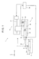
- a form measuring instrument 1 is adapted to measure a surface profile of a workpiece W mounted on a table 2.
- the form measuring instrument 1 includes: a body 10; a movable member 20 being rotatably supported by the body 10; and a tip of a stylus 21 being provided at an end of the movable member 20, the tip 21 being moved in a measurement direction (an X-axis direction in this exemplary embodiment) for a measurement operation while being in contact with a workpiece surface S.
- a Z-axial displacement of the tip of the stylus 21 is detected from a rotation condition of the movable member 20 during the measurement operation to measure a surface profile of the workpiece W (a contour in an X-Z plane).
- the body 10 is supported by a support 11 and can be moved in the X-axis direction by a feed mechanism 12 provided in the support 11.
- the support 11 may be supported by a column (not shown) located near the table 2.
- the support 11 may be vertically movable along the column.
- the support 11 may be located near the table 2 without using the column. In other words, as long as the tip of the stylus 21 can be in contact with the workpiece surface S and moved in the X-axis direction, the support 11 may be arranged in any manner.
- the feed mechanism 12 moves the body 10 relative to the support 11 for the above-described measurement operation and may be provided by a precise mechanical feed mechanism using, for instance, a ball screw extending in the X-axis direction or, alternatively, by a device such as a linear motor capable of a linear motion and a high-accuracy positioning.
- a controller 30 is connected to the feed mechanism 12.
- the controller 30 is provided by a personal computer or the like and controls an operation of the feed mechanism 12 based on a prestored operation program.
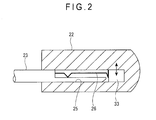
- the movable member 20 includes: a stylus holder 22 being supported by the body 10; a stylus 23 being held by the stylus holder 22; and the tip 21 projecting downward from one end of the stylus 23.
- the stylus holder 22 extends in the X-axis direction and is supported by a turn shaft 24 in a rotatable manner relative to the body 10. When the stylus holder 22 swings, one end of the stylus holder 22 moves in the Z-axis direction.
- the stylus 23 is connected to the one end of the stylus holder 22 and extends in the X-axis direction on an extension of the stylus holder 22.
- the turn shaft 24 is provided by a ball bearing or a sliding bearing using a low-friction material and is located along an axis in a figure-intersecting direction (i.e., a Y-axis direction intersecting with the X-axis and Z-axis).
- the tip of the stylus 21 is fixed to be oriented downward in the Z-axis direction in the vicinity of the end of the stylus 23.
- the tip of the stylus 21 is formed in the shape of a round bar as a whole but an end of the tip of the stylus 21 is formed in a conical shape.
- the conical surface of the tip of the stylus 21 is provided with DLC (diamond-like carbon coating) to ensure wear resistance and low-friction properties.
- the stylus holder 22 includes: a connecting portion 25 in which an end of the stylus 23 can be inserted; and a clip member 26 being made of an elastic material, the clip member 26 being located inside the connecting portion 25.
- the stylus 23 when the end of the stylus 23 is inserted in the connecting portion 25, the stylus 23 is held coaxially with the stylus holder 22 while being pressed by the clip member 26 to be prevented from dropping out.
- the stylus 23 in the above state can be pulled out of the connecting portion 25 with a force larger than a holding force of the clip member 26 in order to replace the stylus 23 with another one.
- the form measuring instrument 1 further includes: a measurement-force-applying unit 31 that generates a rotation force acting on the stylus holder 22 to bring the tip of the stylus 21 into contact with the workpiece surface; a displacement detector 32 that is provided to a portion of the stylus holder 22 to detect a displacement of the stylus holder 22 resulting from the rotation thereof; and a vibration generator 33 that applies vibration to the stylus holder 22.
- the measurement-force-applying unit 31 is a mechanical biasing unit including a coil spring.
- the measurement-force-applying unit 31 is located at the side opposite to the tip of the stylus 21 across the turn shaft 24 of the stylus holder 22 and interposed between the body 10 and the stylus holder 22.
- the measurement-force-applying unit 31 serves to bias an end of the stylus holder 22 upward in the Z-axis direction while biasing the stylus 23 and the tip of the stylus 21 downward in the Z-axis direction at the opposite side, thereby bringing the tip of the stylus 21 into contact with the workpiece surface S with a predetermined measurement force.
- the measurement-force-applying unit 31 may be provided by a device made of an elastomeric material instead of an elastic member such as a coil spring. Further alternatively, the measurement-force-applying unit 31 may be provided by a device capable of electromagnetically generating a measurement force or generating a measurement force using a gravity balance. The measurement-force-applying unit 31 may be installed anywhere on/in the movable member 20 as long as the measurement-force-applying unit 31 can apply the predetermined measurement force.
- the displacement detector 32 which is located at the side opposite to the tip of the stylus 21 across the turn shaft 24 of the stylus holder 22, detects a Z-axial displacement of a specific portion of the stylus holder 22 to detect a rotation angle of the stylus holder 22.
- a Z-axial displacement of the tip of the stylus 21 is calculated from the detected rotation angle and a distance between the tip of the stylus 21 and the turn shaft 24.
- the signal processing and the calculation are performed by a processing program of the above-described controller 30.
- the displacement detector 32 detects a displacement of a portion of the stylus holder 22
- the displacement may be electromagnetically detected with a differential coil or the like or may be optically detected.
- the vibration generator 33 which is fixed at the innermost of the connecting portion 25 of the stylus holder 22, applies vibration in a direction intersecting with the measurement direction (X-axis direction) to the stylus holder 22, stylus 23 and the tip of the stylus 21.
- the vibration generator 33 includes an electrostrictive element such as a piezoelectric element that oscillates in response to an electric signal from the controller 30.
- the measurement operation is performed under the control of the controller 30.
- the workpiece W is mounted on the table 2 and the body 10 is set with the tip of the stylus 21 being in contact with the workpiece surface S.
- the feed mechanism 12 moves the movable member 20 in the X-axis direction and a detection signal from the displacement detector 32 is recorded during the movement of the movable member 20, thereby measuring a profile of the workpiece surface S in the form of a Z-axial displacement along the X axis direction.
- vibration is applied to the tip of the stylus 21 by the vibration generator 33.
- a vibration V is applied from the above-described vibration generator 33 (see Fig. 1 ).
- the application of the vibration V reduces a friction force of the tip of the stylus 21 on the workpiece surface S during the measurement operation Mx to let the tip of the stylus 21 continuously and smoothly move on the workpiece surface S.
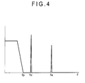
- a frequency fa of the vibration V applied by the vibration generator 33 is higher than a natural frequency fo of the movable member 20 in the exemplary embodiment.
- the signal from the stylus holder 22 detected by the displacement detector 32 is processed by the controller 30 to be measured as a Z-axial displacement along the X-axis direction. Additionally, the controller 30 performs a low-pass filter processing so that only a frequency component equal to or lower than a frequency fp lower than the natural frequency fo of the movable member 20 passes.
- the natural frequency fo of the movable member 20 is measured and stored in the controller 30 in advance.
- the signal detected by the displacement detector 32 is not affected by the vibration V applied by the vibration generator 33, thereby stably and reliably measuring the displacement of the tip of the stylus 21 in the measurement direction (Z-axis direction), i.e., the profile of the workpiece surface S.
- the vibration V applied by the vibration generator 33 serves to reduce the friction force of the tip of the stylus 21 on the workpiece surface S to let the tip of the stylus 21 continuously and smoothly move on the workpiece surface S.
- the vibration V applied by the vibration generator 33 is adjusted as shown in Fig. 4 so as not to affect the signal detected by the displacement detector 32, thereby stably and reliably measuring the profile of the workpiece surface S.
- the vibration generator 33 is located near the tip of the stylus 21 relative to the turn shaft 24 of the stylus holder 22, thereby reliably and efficiently applying the vibration to the tip of the stylus 21.
- the vibration generator 33 is left in the stylus holder 22 even when the tip of the stylus 21 and the stylus 23 are removed for replacement, so that the vibration generator 33 can be shared among a plurality of substitute tips 21 and styluses 23.
- the connecting portion 25 intended to connect the stylus 23 is used to install the vibration generator 33 in the stylus holder 22 without using a dedicated enclosure or the like, thereby simplifying the arrangement for easy manufacturing.
- the displacement detector 32 is located at the side opposite to the tip of the stylus 21 across the turn shaft 24 of the stylus holder 22, thereby avoiding, for instance, mechanical interference with the stylus 23 and the tip of the stylus 21 and thus ensuring the installation flexibility. Especially, even when the vibration generator 33 is located near the tip of the stylus 21 relative to the turn shaft 24 of the stylus holder 22, respective installation spaces can be efficiently ensured.
- Fig. 5 shows a second exemplary embodiment of the invention.
- This exemplary embodiment has the same arrangement as the form measuring instrument 1 according to the first exemplary embodiment except that the vibration generator 33 is provided not in the connecting portion 25 but in the vicinity of the turn shaft 24.
- This exemplary embodiment also offers the same effects as the first exemplary embodiment.
- this exemplary embodiment requires an additional processing for, for instance, forming a hole or the like in the stylus holder 22 to enclose the vibration generator 33 therein.
- the vibration generator 33 is closer to the turn shaft 24 and remoter from the tip of the stylus 21, so that the second exemplary embodiment is inefficient and unfavorable in terms of vibration transmission to the tip of the stylus 21 as compared with the first exemplary embodiment.
- the vibration generator 33 when the vibration generator 33 is provided to the stylus 23, the vibration generator 33 is necessarily removed with the stylus 23 for replacement. In contrast, when the vibration generator 33 is located at the opposite side of the stylus holder 22 (i.e., the side opposite to the stylus 23 across the turn shaft 24), the vibration from the vibration generator 33 may be insufficiently transmitted to the tip of the stylus 21.
- the vibration generator 33 is preferably located somewhere within a section from the turn shaft 24 to the end of the stylus holder 22 provided with the stylus 23 (i.e., a section A shown in Fig. 5 ).
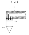
- Fig. 6 shows an example describing the technical background for understanding the invention.
- This example has the same arrangement as the form measuring instrument 1 according to the first exemplary embodiment except that the vibration generator 33 is provided not in the stylus holder 22 but in the stylus 23 at a portion supporting the tip of the stylus 21.
- This example also offers the same effects as the first exemplary embodiment.
- the vibration generator 33 is provided not in the stylus holder 22 but in the stylus 23, the vibration generator 33 is necessarily provided in each of possibly chosen styluses 23, which results in an increased installation cost. Further, replacement of the stylus 23 requires connection and disconnection of a signal line between the vibration generator 33 and the controller 30.
- the vibration generator 33 is provided in the stylus 23 at the portion supporting the tip of the stylus 21, the vibration from the vibration generator 33 is directly transmitted to the tip of the stylus 21, thereby maximizing the energy efficiency of the vibration transmission and maximizing the responsibility of the vibration.
- respective installation positions, mechanisms, types of the measurement-force-applying unit 31, the displacement detector 32 and the vibration generator 33 may be altered as necessary.
- the vibration generator 33 is only intended to apply the vibration V in the exemplary embodiments, the vibration generator 33 may apply, for instance, vibration in the Y-axis direction or X-axis direction intersecting with the Z-axis direction instead of the Z-axial vibration that makes the stylus holder 22 move around the turn shaft 24 thereof.
- piezoelectric elements may be assembled together in mutually intersecting directions to provide the vibration generator 33, thereby allowing the vibration generator 33 to apply bidirectional vibration including a vibration Vz in the Z-axis direction and another vibration Vy or Vx in the Y- or X-axis direction intersecting with the Z-axis direction.
- the vibration generator 33 may apply the vibration Vz in the Z-axis direction and the vibration Vy in the Y-axis direction.
- the vibration V of the end of the tip of the stylus 21 can have a variety of modes by adjusting a phase difference between the vibrations Vz and Vy. For instance, as shown in Fig. 7 , when the phase difference between the vibrations Vz and Vy is 0 degrees, the end of the tip of the stylus 21 can be subjected to the vibration V within an imaginary plane inclined relative to the X-direction and Y-direction.
- Such various modes of the vibration V are controllable by an input signal from the controller 30 to the vibration generator 33.
- the tip of the stylus is moved along a workpiece surface while being vibrated, thereby avoiding a non-smooth movement (i.e., stick-slip) of the tip of the stylus on the workpiece surface.
- the invention is also effective in preventing the tip of the stylus from being caught by a step, a projection or the like on a workpiece surface in cooperation with a conical shape of the tip of the stylus.
- a typical tip of a stylus is formed in a downward-pointing conical shape and the peak of the conical shape is usually brought into slide-contact with the workpiece surface.
- the tip of the stylus may be caught by the step during the movement for the measurement operation to be hindered from moving further.
- the upper edge of the step comes into contact with a side wall of the conical shape of the tip of the stylus before the peak of the conical shape reaches the step and then the upper edge of the step slides along the slope of the conical shape.
- the upper edge of the step smoothly slides on the surface of the conical shape during the movement for the measurement operation and, consequently, the peak of the conical shape reaches the upper edge of the step (i.e., the tip of the stylus finishes climbing up the step) and then passes over the step.
- the tip of the stylus cannot smoothly pass over the step unless the upper edge of the step smoothly slides on the surface of the conical shape of the tip of the stylus.
- a friction coefficient of the side wall of the cone needs to be reduced for the smooth sliding.
- friction is reduced by applying vibration to the tip of the stylus and a DLC coating is applied to the surface of the tip of the stylus, thereby further effectively helping the tip of the stylus pass over the step.
Landscapes
- Physics & Mathematics (AREA)
- General Physics & Mathematics (AREA)
- A Measuring Device Byusing Mechanical Method (AREA)
Applications Claiming Priority (1)
| Application Number | Priority Date | Filing Date | Title |
|---|---|---|---|
| JP2013039485A JP6122312B2 (ja) | 2013-02-28 | 2013-02-28 | 形状測定機 |
Publications (2)
| Publication Number | Publication Date |
|---|---|
| EP2772722A1 EP2772722A1 (en) | 2014-09-03 |
| EP2772722B1 true EP2772722B1 (en) | 2015-09-02 |
Family
ID=50179467
Family Applications (1)
| Application Number | Title | Priority Date | Filing Date |
|---|---|---|---|
| EP14000622.2A Active EP2772722B1 (en) | 2013-02-28 | 2014-02-21 | Form measuring instrument |
Country Status (3)
| Country | Link |
|---|---|
| US (1) | US9285201B2 (enExample) |
| EP (1) | EP2772722B1 (enExample) |
| JP (1) | JP6122312B2 (enExample) |
Families Citing this family (19)
| Publication number | Priority date | Publication date | Assignee | Title |
|---|---|---|---|---|
| JPH0656535B2 (ja) | 1983-12-17 | 1994-07-27 | キヤノン株式会社 | 定着装置 |
| JP6122312B2 (ja) * | 2013-02-28 | 2017-04-26 | 株式会社ミツトヨ | 形状測定機 |
| JP6189153B2 (ja) * | 2013-09-18 | 2017-08-30 | 株式会社ミツトヨ | 梃子式測定器 |
| JP6361243B2 (ja) * | 2014-04-07 | 2018-07-25 | 株式会社ジェイテクト | 加工変質検出センサを備える工作機械 |
| JP6282517B2 (ja) * | 2014-04-09 | 2018-02-21 | 株式会社ミツトヨ | 形状測定機 |
| JP6447997B2 (ja) * | 2015-02-09 | 2019-01-09 | 株式会社ミツトヨ | テストインジケータ |
| CN105018333B (zh) * | 2015-08-24 | 2017-03-08 | 苏州大学张家港工业技术研究院 | 一种基于粘滑驱动原理的显微注射机构 |
| JP6680643B2 (ja) * | 2016-08-03 | 2020-04-15 | 株式会社Soken | 面圧計測装置 |
| RU2659324C1 (ru) * | 2017-06-15 | 2018-06-29 | федеральное государственное бюджетное образовательное учреждение высшего образования "Тольяттинский государственный университет" | Способ контроля диаметров и формы миниатюрных цилиндрических несимметричных деталей |
| JP2019100874A (ja) | 2017-12-04 | 2019-06-24 | 株式会社ミツトヨ | 形状測定装置 |
| KR101944080B1 (ko) * | 2018-07-24 | 2019-01-30 | 황재은 | 형상측정기 |
| US11150731B2 (en) * | 2018-09-28 | 2021-10-19 | Apple Inc. | Multi-modal haptic feedback for an electronic device using a single haptic actuator |
| JP7261560B2 (ja) * | 2018-10-31 | 2023-04-20 | 株式会社ミツトヨ | 表面性状測定方法および表面性状測定装置 |
| KR102180526B1 (ko) * | 2019-08-16 | 2020-11-18 | 한양대학교 산학협력단 | 휴대용 표면 측정 장치 및 제어 방법 |
| JP7448323B2 (ja) * | 2019-09-06 | 2024-03-12 | 株式会社ミツトヨ | 粗さ測定機 |
| JPWO2021106075A1 (enExample) * | 2019-11-26 | 2021-06-03 | ||
| DE102020108406A1 (de) * | 2020-03-26 | 2021-09-30 | Carl Zeiss Industrielle Messtechnik Gmbh | Taktiler oder/und optischer Abstandssensor, System mit einem solchen Abstandssensor und Verfahren zur Kalibrierung eines solchen Abstandssensors oder eines solchen Systems |
| TWI731650B (zh) * | 2020-04-15 | 2021-06-21 | 宏碁股份有限公司 | 觸控筆、觸控電子裝置與觸控系統 |
| JP7361261B2 (ja) * | 2020-05-14 | 2023-10-16 | 株式会社東京精密 | 形状測定機及びその制御方法 |
Family Cites Families (21)
| Publication number | Priority date | Publication date | Assignee | Title |
|---|---|---|---|---|
| JPS5343418B2 (enExample) * | 1973-09-28 | 1978-11-20 | ||
| JPS60161503A (ja) * | 1984-02-01 | 1985-08-23 | Tokyo Seimitsu Co Ltd | 表面粗さ測定機用検出装置 |
| US5189806A (en) * | 1988-12-19 | 1993-03-02 | Renishaw Plc | Method of and apparatus for scanning the surface of a workpiece |
| JPH0294050U (enExample) * | 1989-01-12 | 1990-07-26 | ||
| JP2539998B2 (ja) | 1992-10-14 | 1996-10-02 | 株式会社ミツトヨ | 形状測定機 |
| GB9612383D0 (en) * | 1995-12-07 | 1996-08-14 | Rank Taylor Hobson Ltd | Surface form measurement |
| SE9600078L (sv) * | 1996-01-09 | 1997-05-12 | Johansson Ab C E | Anordning för dimensionsbestämning av tredimensionella mätobjekt |
| IT1299902B1 (it) * | 1998-03-13 | 2000-04-04 | Marposs Spa | Testa, apparecchiatura e metodo per il controllo di dimensioni lineari di pezzi meccanici. |
| JP3992853B2 (ja) * | 1998-09-30 | 2007-10-17 | 株式会社ミツトヨ | 表面追従型測定機 |
| JP2000199710A (ja) * | 1999-01-06 | 2000-07-18 | Mitsutoyo Corp | タッチ信号プロ―ブの接触部位検出構造 |
| JP3650555B2 (ja) | 1999-09-27 | 2005-05-18 | 株式会社ミツトヨ | タッチセンサ |
| JP3819250B2 (ja) * | 2000-05-15 | 2006-09-06 | 株式会社ミツトヨ | 加振型接触検出センサ |
| JP4688400B2 (ja) | 2001-12-04 | 2011-05-25 | エスアイアイ・ナノテクノロジー株式会社 | 走査型プローブ顕微鏡用探針 |
| GB0608998D0 (en) * | 2006-05-08 | 2006-06-14 | Renishaw Plc | Contact sensing probe |
| JP5009564B2 (ja) * | 2006-07-20 | 2012-08-22 | 株式会社ミツトヨ | 表面追従型測定器 |
| JP5108619B2 (ja) * | 2008-05-15 | 2012-12-26 | 株式会社ミツトヨ | センサ信号検知回路 |
| JP5297735B2 (ja) * | 2008-09-18 | 2013-09-25 | 国立大学法人東北大学 | 接触式変位センサ |
| JP5451180B2 (ja) * | 2009-05-22 | 2014-03-26 | 株式会社ミツトヨ | 真円度測定機 |
| JP4968600B1 (ja) * | 2011-01-13 | 2012-07-04 | 株式会社東京精密 | 真円度測定装置及びその心ずれ量補正方法 |
| JP5754971B2 (ja) * | 2011-02-14 | 2015-07-29 | キヤノン株式会社 | 形状測定装置及び形状測定方法 |
| JP6122312B2 (ja) * | 2013-02-28 | 2017-04-26 | 株式会社ミツトヨ | 形状測定機 |
-
2013
- 2013-02-28 JP JP2013039485A patent/JP6122312B2/ja active Active
-
2014
- 2014-02-21 EP EP14000622.2A patent/EP2772722B1/en active Active
- 2014-02-26 US US14/190,452 patent/US9285201B2/en active Active
Also Published As
| Publication number | Publication date |
|---|---|
| JP6122312B2 (ja) | 2017-04-26 |
| US20140237834A1 (en) | 2014-08-28 |
| US9285201B2 (en) | 2016-03-15 |
| JP2014167435A (ja) | 2014-09-11 |
| EP2772722A1 (en) | 2014-09-03 |
Similar Documents
| Publication | Publication Date | Title |
|---|---|---|
| EP2772722B1 (en) | Form measuring instrument | |
| JP3926793B2 (ja) | 表面形状測定装置 | |
| JP5336279B2 (ja) | 表面性状測定装置および真円度測定装置 | |
| US8302456B2 (en) | Active damping of high speed scanning probe microscope components | |
| JP4909548B2 (ja) | 表面形状測定装置 | |
| JP5639934B2 (ja) | 表面性状測定機 | |
| US10507560B2 (en) | Apparatus movable by a coordinate measuring machine for positioning a measuring instrument with respect to a workpiece | |
| EP2314981B1 (en) | Measuring force control apparatus | |
| JP6216400B2 (ja) | 測定プローブ | |
| JP5580163B2 (ja) | 実装装置の平行度調整方法および平行度調整装置 | |
| US20060225505A1 (en) | Contact-type displacement measuring apparatus | |
| US6457366B1 (en) | Movement control mechanism of contact-type vibrating probe | |
| JP2006300823A (ja) | 表面粗さ/輪郭形状測定装置 | |
| JP6788207B2 (ja) | 変位検出器、表面性状測定機、及び真円度測定機 | |
| JP7073211B2 (ja) | 表面性状測定装置の制御方法 | |
| CN1157653A (zh) | 测量触针组件 | |
| KR20120085770A (ko) | 촉침식 측정 장치 | |
| JP4833051B2 (ja) | 摩擦試験装置及び摩擦試験方法 | |
| JP2007121260A (ja) | 触針式形状測定装置及び方法とこれに適した回転規制エアシリンダ | |
| JP4909562B2 (ja) | 表面性状測定装置 | |
| JP2000298013A (ja) | 形状測定用プローブ | |
| JP7038308B2 (ja) | 表面形状測定機 | |
| JP2011064464A (ja) | 形状測定装置 | |
| JPH0821720A (ja) | 直動案内機構及び三次元変位プローブ | |
| WO2015093244A1 (ja) | 測定プローブ及び形状測定装置 |
Legal Events
| Date | Code | Title | Description |
|---|---|---|---|
| PUAI | Public reference made under article 153(3) epc to a published international application that has entered the european phase |
Free format text: ORIGINAL CODE: 0009012 |
|
| 17P | Request for examination filed |
Effective date: 20140221 |
|
| AK | Designated contracting states |
Kind code of ref document: A1 Designated state(s): AL AT BE BG CH CY CZ DE DK EE ES FI FR GB GR HR HU IE IS IT LI LT LU LV MC MK MT NL NO PL PT RO RS SE SI SK SM TR |
|
| AX | Request for extension of the european patent |
Extension state: BA ME |
|
| RAP1 | Party data changed (applicant data changed or rights of an application transferred) |
Owner name: MITUTOYO CORPORATION |
|
| GRAP | Despatch of communication of intention to grant a patent |
Free format text: ORIGINAL CODE: EPIDOSNIGR1 |
|
| R17P | Request for examination filed (corrected) |
Effective date: 20150219 |
|
| RBV | Designated contracting states (corrected) |
Designated state(s): AL AT BE BG CH CY CZ DE DK EE ES FI FR GB GR HR HU IE IS IT LI LT LU LV MC MK MT NL NO PL PT RO RS SE SI SK SM TR |
|
| INTG | Intention to grant announced |
Effective date: 20150323 |
|
| GRAS | Grant fee paid |
Free format text: ORIGINAL CODE: EPIDOSNIGR3 |
|
| GRAA | (expected) grant |
Free format text: ORIGINAL CODE: 0009210 |
|
| AK | Designated contracting states |
Kind code of ref document: B1 Designated state(s): AL AT BE BG CH CY CZ DE DK EE ES FI FR GB GR HR HU IE IS IT LI LT LU LV MC MK MT NL NO PL PT RO RS SE SI SK SM TR |
|
| REG | Reference to a national code |
Ref country code: GB Ref legal event code: FG4D |
|
| REG | Reference to a national code |
Ref country code: AT Ref legal event code: REF Ref document number: 746887 Country of ref document: AT Kind code of ref document: T Effective date: 20150915 Ref country code: CH Ref legal event code: EP |
|
| REG | Reference to a national code |
Ref country code: IE Ref legal event code: FG4D |
|
| REG | Reference to a national code |
Ref country code: DE Ref legal event code: R096 Ref document number: 602014000161 Country of ref document: DE |
|
| REG | Reference to a national code |
Ref country code: AT Ref legal event code: MK05 Ref document number: 746887 Country of ref document: AT Kind code of ref document: T Effective date: 20150902 |
|
| PG25 | Lapsed in a contracting state [announced via postgrant information from national office to epo] |
Ref country code: NO Free format text: LAPSE BECAUSE OF FAILURE TO SUBMIT A TRANSLATION OF THE DESCRIPTION OR TO PAY THE FEE WITHIN THE PRESCRIBED TIME-LIMIT Effective date: 20151202 Ref country code: GR Free format text: LAPSE BECAUSE OF FAILURE TO SUBMIT A TRANSLATION OF THE DESCRIPTION OR TO PAY THE FEE WITHIN THE PRESCRIBED TIME-LIMIT Effective date: 20151203 Ref country code: FI Free format text: LAPSE BECAUSE OF FAILURE TO SUBMIT A TRANSLATION OF THE DESCRIPTION OR TO PAY THE FEE WITHIN THE PRESCRIBED TIME-LIMIT Effective date: 20150902 Ref country code: LT Free format text: LAPSE BECAUSE OF FAILURE TO SUBMIT A TRANSLATION OF THE DESCRIPTION OR TO PAY THE FEE WITHIN THE PRESCRIBED TIME-LIMIT Effective date: 20150902 Ref country code: LV Free format text: LAPSE BECAUSE OF FAILURE TO SUBMIT A TRANSLATION OF THE DESCRIPTION OR TO PAY THE FEE WITHIN THE PRESCRIBED TIME-LIMIT Effective date: 20150902 |
|
| REG | Reference to a national code |
Ref country code: LT Ref legal event code: MG4D Ref country code: NL Ref legal event code: MP Effective date: 20150902 |
|
| PG25 | Lapsed in a contracting state [announced via postgrant information from national office to epo] |
Ref country code: PL Free format text: LAPSE BECAUSE OF FAILURE TO SUBMIT A TRANSLATION OF THE DESCRIPTION OR TO PAY THE FEE WITHIN THE PRESCRIBED TIME-LIMIT Effective date: 20150902 Ref country code: RS Free format text: LAPSE BECAUSE OF FAILURE TO SUBMIT A TRANSLATION OF THE DESCRIPTION OR TO PAY THE FEE WITHIN THE PRESCRIBED TIME-LIMIT Effective date: 20150902 Ref country code: SE Free format text: LAPSE BECAUSE OF FAILURE TO SUBMIT A TRANSLATION OF THE DESCRIPTION OR TO PAY THE FEE WITHIN THE PRESCRIBED TIME-LIMIT Effective date: 20150902 Ref country code: AT Free format text: LAPSE BECAUSE OF FAILURE TO SUBMIT A TRANSLATION OF THE DESCRIPTION OR TO PAY THE FEE WITHIN THE PRESCRIBED TIME-LIMIT Effective date: 20150902 Ref country code: ES Free format text: LAPSE BECAUSE OF FAILURE TO SUBMIT A TRANSLATION OF THE DESCRIPTION OR TO PAY THE FEE WITHIN THE PRESCRIBED TIME-LIMIT Effective date: 20150902 |
|
| PG25 | Lapsed in a contracting state [announced via postgrant information from national office to epo] |
Ref country code: SK Free format text: LAPSE BECAUSE OF FAILURE TO SUBMIT A TRANSLATION OF THE DESCRIPTION OR TO PAY THE FEE WITHIN THE PRESCRIBED TIME-LIMIT Effective date: 20150902 Ref country code: IS Free format text: LAPSE BECAUSE OF FAILURE TO SUBMIT A TRANSLATION OF THE DESCRIPTION OR TO PAY THE FEE WITHIN THE PRESCRIBED TIME-LIMIT Effective date: 20160102 Ref country code: CZ Free format text: LAPSE BECAUSE OF FAILURE TO SUBMIT A TRANSLATION OF THE DESCRIPTION OR TO PAY THE FEE WITHIN THE PRESCRIBED TIME-LIMIT Effective date: 20150902 Ref country code: EE Free format text: LAPSE BECAUSE OF FAILURE TO SUBMIT A TRANSLATION OF THE DESCRIPTION OR TO PAY THE FEE WITHIN THE PRESCRIBED TIME-LIMIT Effective date: 20150902 Ref country code: IT Free format text: LAPSE BECAUSE OF FAILURE TO SUBMIT A TRANSLATION OF THE DESCRIPTION OR TO PAY THE FEE WITHIN THE PRESCRIBED TIME-LIMIT Effective date: 20150902 Ref country code: NL Free format text: LAPSE BECAUSE OF FAILURE TO SUBMIT A TRANSLATION OF THE DESCRIPTION OR TO PAY THE FEE WITHIN THE PRESCRIBED TIME-LIMIT Effective date: 20150902 |
|
| PG25 | Lapsed in a contracting state [announced via postgrant information from national office to epo] |
Ref country code: PT Free format text: LAPSE BECAUSE OF FAILURE TO SUBMIT A TRANSLATION OF THE DESCRIPTION OR TO PAY THE FEE WITHIN THE PRESCRIBED TIME-LIMIT Effective date: 20160104 Ref country code: RO Free format text: LAPSE BECAUSE OF FAILURE TO SUBMIT A TRANSLATION OF THE DESCRIPTION OR TO PAY THE FEE WITHIN THE PRESCRIBED TIME-LIMIT Effective date: 20150902 Ref country code: BE Free format text: LAPSE BECAUSE OF NON-PAYMENT OF DUE FEES Effective date: 20160229 |
|
| REG | Reference to a national code |
Ref country code: DE Ref legal event code: R097 Ref document number: 602014000161 Country of ref document: DE |
|
| PLBE | No opposition filed within time limit |
Free format text: ORIGINAL CODE: 0009261 |
|
| STAA | Information on the status of an ep patent application or granted ep patent |
Free format text: STATUS: NO OPPOSITION FILED WITHIN TIME LIMIT |
|
| 26N | No opposition filed |
Effective date: 20160603 |
|
| PG25 | Lapsed in a contracting state [announced via postgrant information from national office to epo] |
Ref country code: DK Free format text: LAPSE BECAUSE OF FAILURE TO SUBMIT A TRANSLATION OF THE DESCRIPTION OR TO PAY THE FEE WITHIN THE PRESCRIBED TIME-LIMIT Effective date: 20150902 Ref country code: SI Free format text: LAPSE BECAUSE OF FAILURE TO SUBMIT A TRANSLATION OF THE DESCRIPTION OR TO PAY THE FEE WITHIN THE PRESCRIBED TIME-LIMIT Effective date: 20150902 |
|
| PG25 | Lapsed in a contracting state [announced via postgrant information from national office to epo] |
Ref country code: MC Free format text: LAPSE BECAUSE OF FAILURE TO SUBMIT A TRANSLATION OF THE DESCRIPTION OR TO PAY THE FEE WITHIN THE PRESCRIBED TIME-LIMIT Effective date: 20150902 Ref country code: LU Free format text: LAPSE BECAUSE OF FAILURE TO SUBMIT A TRANSLATION OF THE DESCRIPTION OR TO PAY THE FEE WITHIN THE PRESCRIBED TIME-LIMIT Effective date: 20160221 |
|
| REG | Reference to a national code |
Ref country code: FR Ref legal event code: ST Effective date: 20161028 |
|
| REG | Reference to a national code |
Ref country code: IE Ref legal event code: MM4A |
|
| PG25 | Lapsed in a contracting state [announced via postgrant information from national office to epo] |
Ref country code: BE Free format text: LAPSE BECAUSE OF FAILURE TO SUBMIT A TRANSLATION OF THE DESCRIPTION OR TO PAY THE FEE WITHIN THE PRESCRIBED TIME-LIMIT Effective date: 20150902 |
|
| PG25 | Lapsed in a contracting state [announced via postgrant information from national office to epo] |
Ref country code: FR Free format text: LAPSE BECAUSE OF NON-PAYMENT OF DUE FEES Effective date: 20160229 Ref country code: IE Free format text: LAPSE BECAUSE OF NON-PAYMENT OF DUE FEES Effective date: 20160221 |
|
| PG25 | Lapsed in a contracting state [announced via postgrant information from national office to epo] |
Ref country code: MT Free format text: LAPSE BECAUSE OF FAILURE TO SUBMIT A TRANSLATION OF THE DESCRIPTION OR TO PAY THE FEE WITHIN THE PRESCRIBED TIME-LIMIT Effective date: 20150902 |
|
| REG | Reference to a national code |
Ref country code: CH Ref legal event code: PL |
|
| PG25 | Lapsed in a contracting state [announced via postgrant information from national office to epo] |
Ref country code: LI Free format text: LAPSE BECAUSE OF NON-PAYMENT OF DUE FEES Effective date: 20170228 Ref country code: CH Free format text: LAPSE BECAUSE OF NON-PAYMENT OF DUE FEES Effective date: 20170228 |
|
| PG25 | Lapsed in a contracting state [announced via postgrant information from national office to epo] |
Ref country code: CY Free format text: LAPSE BECAUSE OF FAILURE TO SUBMIT A TRANSLATION OF THE DESCRIPTION OR TO PAY THE FEE WITHIN THE PRESCRIBED TIME-LIMIT Effective date: 20150902 Ref country code: HU Free format text: LAPSE BECAUSE OF FAILURE TO SUBMIT A TRANSLATION OF THE DESCRIPTION OR TO PAY THE FEE WITHIN THE PRESCRIBED TIME-LIMIT; INVALID AB INITIO Effective date: 20140221 Ref country code: SM Free format text: LAPSE BECAUSE OF FAILURE TO SUBMIT A TRANSLATION OF THE DESCRIPTION OR TO PAY THE FEE WITHIN THE PRESCRIBED TIME-LIMIT Effective date: 20150902 |
|
| PG25 | Lapsed in a contracting state [announced via postgrant information from national office to epo] |
Ref country code: HR Free format text: LAPSE BECAUSE OF FAILURE TO SUBMIT A TRANSLATION OF THE DESCRIPTION OR TO PAY THE FEE WITHIN THE PRESCRIBED TIME-LIMIT Effective date: 20150902 Ref country code: MK Free format text: LAPSE BECAUSE OF FAILURE TO SUBMIT A TRANSLATION OF THE DESCRIPTION OR TO PAY THE FEE WITHIN THE PRESCRIBED TIME-LIMIT Effective date: 20150902 Ref country code: MT Free format text: LAPSE BECAUSE OF FAILURE TO SUBMIT A TRANSLATION OF THE DESCRIPTION OR TO PAY THE FEE WITHIN THE PRESCRIBED TIME-LIMIT Effective date: 20160229 Ref country code: TR Free format text: LAPSE BECAUSE OF FAILURE TO SUBMIT A TRANSLATION OF THE DESCRIPTION OR TO PAY THE FEE WITHIN THE PRESCRIBED TIME-LIMIT Effective date: 20150902 |
|
| PG25 | Lapsed in a contracting state [announced via postgrant information from national office to epo] |
Ref country code: BG Free format text: LAPSE BECAUSE OF FAILURE TO SUBMIT A TRANSLATION OF THE DESCRIPTION OR TO PAY THE FEE WITHIN THE PRESCRIBED TIME-LIMIT Effective date: 20150902 |
|
| PG25 | Lapsed in a contracting state [announced via postgrant information from national office to epo] |
Ref country code: AL Free format text: LAPSE BECAUSE OF FAILURE TO SUBMIT A TRANSLATION OF THE DESCRIPTION OR TO PAY THE FEE WITHIN THE PRESCRIBED TIME-LIMIT Effective date: 20150902 |
|
| PGFP | Annual fee paid to national office [announced via postgrant information from national office to epo] |
Ref country code: DE Payment date: 20250218 Year of fee payment: 12 |
|
| PGFP | Annual fee paid to national office [announced via postgrant information from national office to epo] |
Ref country code: GB Payment date: 20250219 Year of fee payment: 12 |